WO2013141093A1 - ペーパーホルダー - Google Patents
ペーパーホルダー Download PDFInfo
- Publication number
- WO2013141093A1 WO2013141093A1 PCT/JP2013/056876 JP2013056876W WO2013141093A1 WO 2013141093 A1 WO2013141093 A1 WO 2013141093A1 JP 2013056876 W JP2013056876 W JP 2013056876W WO 2013141093 A1 WO2013141093 A1 WO 2013141093A1
- Authority
- WO
- WIPO (PCT)
- Prior art keywords
- paper
- blade
- surface section
- surface portion
- holding piece
- Prior art date
- Legal status (The legal status is an assumption and is not a legal conclusion. Google has not performed a legal analysis and makes no representation as to the accuracy of the status listed.)
- Ceased
Links
Images


Classifications
-
- B—PERFORMING OPERATIONS; TRANSPORTING
- B42—BOOKBINDING; ALBUMS; FILES; SPECIAL PRINTED MATTER
- B42F—SHEETS TEMPORARILY ATTACHED TOGETHER; FILING APPLIANCES; FILE CARDS; INDEXING
- B42F1/00—Sheets temporarily attached together without perforating; Means therefor
- B42F1/006—Fasteners comprising two co-operating jaws closed by spring action and that can be manually opened, e.g. clamps
-
- B—PERFORMING OPERATIONS; TRANSPORTING
- B42—BOOKBINDING; ALBUMS; FILES; SPECIAL PRINTED MATTER
- B42F—SHEETS TEMPORARILY ATTACHED TOGETHER; FILING APPLIANCES; FILE CARDS; INDEXING
- B42F1/00—Sheets temporarily attached together without perforating; Means therefor
- B42F1/02—Paper-clips or like fasteners
-
- B—PERFORMING OPERATIONS; TRANSPORTING
- B42—BOOKBINDING; ALBUMS; FILES; SPECIAL PRINTED MATTER
- B42F—SHEETS TEMPORARILY ATTACHED TOGETHER; FILING APPLIANCES; FILE CARDS; INDEXING
- B42F15/00—Suspended filing appliances
- B42F15/0011—Suspended filing appliances for sheets, stacks of temporarily bound sheets
- B42F15/0017—Suspended filing appliances for sheets, stacks of temporarily bound sheets for filing individual loose sheets
- B42F15/0023—Suspended filing appliances for sheets, stacks of temporarily bound sheets for filing individual loose sheets with single suspension means
-
- B—PERFORMING OPERATIONS; TRANSPORTING
- B42—BOOKBINDING; ALBUMS; FILES; SPECIAL PRINTED MATTER
- B42F—SHEETS TEMPORARILY ATTACHED TOGETHER; FILING APPLIANCES; FILE CARDS; INDEXING
- B42F15/00—Suspended filing appliances
- B42F15/0011—Suspended filing appliances for sheets, stacks of temporarily bound sheets
- B42F15/0017—Suspended filing appliances for sheets, stacks of temporarily bound sheets for filing individual loose sheets
- B42F15/0023—Suspended filing appliances for sheets, stacks of temporarily bound sheets for filing individual loose sheets with single suspension means
- B42F15/0029—Suspended filing appliances for sheets, stacks of temporarily bound sheets for filing individual loose sheets with single suspension means suspended in the middle
-
- Y—GENERAL TAGGING OF NEW TECHNOLOGICAL DEVELOPMENTS; GENERAL TAGGING OF CROSS-SECTIONAL TECHNOLOGIES SPANNING OVER SEVERAL SECTIONS OF THE IPC; TECHNICAL SUBJECTS COVERED BY FORMER USPC CROSS-REFERENCE ART COLLECTIONS [XRACs] AND DIGESTS
- Y10—TECHNICAL SUBJECTS COVERED BY FORMER USPC
- Y10T—TECHNICAL SUBJECTS COVERED BY FORMER US CLASSIFICATION
- Y10T24/00—Buckles, buttons, clasps, etc.
- Y10T24/20—Paper fastener
- Y10T24/202—Resiliently biased
- Y10T24/203—Resiliently biased including means to open or close fastener
- Y10T24/204—Pivotally mounted on pintle
Definitions
- the present invention relates to a paper holder in which a straight and beautiful tear mark is left on the drawn paper.
- Patent Document 1 relating to the application of the present applicant states that “a base portion including a bottom surface portion, a top surface portion that faces the bottom surface portion substantially in parallel with a space therebetween, and a substantially U-shape in front view of the top surface portion.
- a front cover portion having a front end formed in a detachable engagement with each other and integrated to form a paper insertion opening below the front end front portion, and provided in the case
- the holding piece is made of a rigid plate-like body, is pivotally supported by a pivotal support provided inside the front end front part, and is pivotally supported, and extends from the pivotal support to the bottom part.
- the blade is fixed to a blade fixing member that holds the blade in a vertical standing state with respect to the holding piece.
- the blade fixing member is provided on a surface of the substrate portion on the paper insertion direction side so that a tip end portion of the blade protrudes from an end portion on the bottom surface portion side of the substrate portion, and an inner surface of the bottom surface portion.
- a paper holder provided with a friction portion for preventing the inserted paper from falling off is described.
- the papers are securely held, and the held paper can be reliably pulled out from the top one by one.
- the pulled paper is linear with a blade.
- the beautiful tear mark remains and dust is hard to be generated.
- the present invention is an improvement of the paper holder described in the above-mentioned Patent Document 1, and securely holds and uses a plurality of sheets in a suspended state in a commercial factory such as a production factory, transportation, or a business space such as an office. It is an object of the present invention to provide a paper holder that is suitable for carrying out and is easy to visually recognize held papers and is more convenient to use.
- a paper holder configured to hold papers in contact with each other, wherein the back surface portion includes an extended back surface portion formed so as to extend longer than a lower end portion of the front surface portion, From the lower end of the extended back portion toward the insertion direction of the paper, the side view is substantially linear.
- the front portion is a transparent, a paper holder.
- paper can be reliably held in a suspended state in a production factory, a commercial activity such as transportation, or a business space such as an office.
- the paper inserted from the insertion slot is securely held in a state where the tip of the blade is inserted into the inserted paper by the spring force of the elastic member acting on the holding piece, and the held paper is moved to the front side. It can be pulled out one by one from the (front side), and a straight, clean tear mark remains on the pulled paper, making it difficult to generate dust.
- the back surface portion includes an extended back surface portion formed so as to extend longer than the lower end portion of the front surface portion, and the side surface from the lower end portion of the extended back surface portion toward the paper insertion direction.
- the paper Since the inclined surface portion extending substantially linearly is provided, the paper is smoothly and surely guided to the insertion port when inserting the paper, and the usability is excellent.
- the front part has transparency, and a holding piece other than the paper and the front part which are the front side (front part side) where the order of drawing out is the first among a plurality of papers. Since no members are present, the entire surface of the held frontmost paper can be visually recognized through the front portion, so that the usability is excellent.
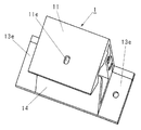
- FIG. 1 is a perspective view of a paper holder 1.
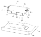
- FIG. FIG. 6 is a perspective view showing a holding piece 20 and a shaft support portion 15.
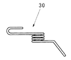
- 3 is a plan view of an elastic member 30.
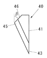
- FIG. 4 is a side view of the blade 40.
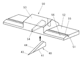
- FIG. 3 is a perspective view of a blade fixing member 50.
- FIG. It is a perspective view which shows the use condition of the paper holder. It is explanatory drawing of operation
- the paper holder 1 includes a case 10 and a holding piece 2 housed in the case 10.
- the case 10 includes a front surface portion 11, a back surface portion 13 that faces the front surface portion 11 substantially in parallel with a space therebetween, and an upper surface portion 12 that connects the front surface portion 11 and the back surface portion 13.
- the insertion port 17 for inserting papers from the lower side is formed between the front part 11 and the back part 13, the insertion port 17 for inserting papers from the lower side is formed.
- overhang portions 13 e are provided on both sides of the back surface portion 13.
- the overhang portion 13e functions as an attachment portion when the paper holder 1 is attached to a plate material or the like.
- the size of the case 10 is not limited, but as an example, when viewed from the front, the height is about 3 to 6 cm, the depth is about 2 to 3 cm, and the width is 4 cm to 7 cm (including the overhanging portion of the back surface portion 13). .) Grades.
- the upper surface portion 12 and the upper portion of the back surface portion 13 are locked, and both are combined to form the case 10.
- Protruding pieces 12b and 12c are formed on the inner surface of the upper surface portion 12 so as to protrude in two front and rear directions at a distance from the hook-shaped portion 12a on the back surface portion 13 side.
- the case 10 is made of a hard synthetic resin material, and includes a front part 11, a piece that is connected to the upper end of the front part 11 and integrally formed with the upper surface part 12, and a locking part that is formed on the upper surface part 12. 12d and 12e and a back surface portion 13 that is detachably locked and integrated, and can be separated by sliding the front surface portion 11 with respect to the back surface portion 13 in the lateral direction. And at least the front part 11 of the case 10 has transparency, and the inside of the front part 11 can be visually recognized.
- the back surface portion 13 includes an extended back surface portion 13 c that is formed to extend longer than the lower end portion 11 a of the front surface portion 11.
- an area of a length h3 obtained by subtracting the length h2 of the front surface portion 11 from the length h1 of the back surface portion 13 is an extended back surface portion 13c.
- An inclined surface portion 14 is formed from the lower end portion of the extended back surface portion 13c so as to extend in a substantially V shape in a side view and extend in a straight line shape in a side view in the paper insertion direction (above the case 10). Yes.
- a paper insertion port 17 is formed between the upper end portion 14 a of the inclined surface portion 14 and the front surface portion 11.
- a shaft support portion 15 for supporting a holding piece 20 to be described later is supported from the inclined surface portion 14 to its inner space (between the back surface portion 13 and the inclined surface portion 14. It is formed so as to protrude into the space.
- the shaft support portion 15 is formed to have a width shorter than the width of the inclined surface portion 14, and the shaft support portion 15 is formed with a hole through which a shaft (not shown) can be inserted in the horizontal direction (case width direction). (See FIG. 3).
- the front portion 11 has a flat outer surface, whereas the inner surface of the front portion 11 has no paper inserted from a position near the insertion port 17 (near the upper end portion 14a of the inclined surface portion 14).
- a rear slope portion 11c having a gentle positive gradient (gradient toward the back side) toward the paper insertion direction is formed.
- a slope portion 11d having a gentle negative gradient from the top of the front slope portion 11b is formed.
- Each slope (inclination angle) of the front slope portion 11b and the rear slope portion 11c is 6 to 20 °, and the height difference between the front slope portion 11b and the rear slope portion 11c (the tip end portion 43 of the blade in a state in which no paper is inserted).
- the height to the top of each slope portion with respect to the level of the inner surface of the front portion 11 is 0.8 to 3 mm, and the length of each of the front slope portion 11b and the rear slope portion 11c is 4 to 10 mm.
- the length between the top part of the front slope part 11b and the top part of the rear slope part 11c is in the range of 12 to 22 mm, which makes it more appropriate to achieve both the ease of inserting paper and the difficulty of falling off. It is preferable from the viewpoint.
- a concave portion having a gentle curve as a whole is formed on the inner surface of the front portion 11, and the top portion of the front slope portion 11b and the top portion of the rear slope portion 11c are formed. Between the blades (intermediate portion) is the tip portion 43 of the blade.
- the front slope portion 11b and the rear slope portion 11c may be formed so as to form a bow or an arc with a gentle curve in addition to a side view and a straight shape.
- the concave portion formed between the front slope portion 11b and the rear slope portion 11c where the blade tip portion 43 is located does not interfere with the operation of the blade tip portion 43. Is for.
- the upper end portion 14a of the inclined surface portion 14 is formed substantially parallel to the front inclined surface portion 11b, and when viewed from the side, the paper insertion port 17 is directed to a position in the vicinity of the tip portion 43 of the blade when no paper is inserted.
- the leading end portion 14b on the paper insertion direction side at the upper end of the inclined surface portion 14 functions as a stopper that restricts the movement of the substrate piece 21 of the holding piece 20 described later in the paper drawing direction.
- the holding piece 20 is pivotally supported by a pivotal support portion 15 provided inside the case 10, and a spring force is urged by an elastic member 30 in the paper drawing direction.
- the holding piece 20 is provided with a blade 40 such that a tip portion 43 of the blade 40 protrudes from the end portion (end portion on the front portion side) toward the front portion 11.
- the holding piece 20 is made of a plate-like body that has been bent and has a required rigidity, and is pivotally supported by a pivotal support portion 15 provided inside the inclined surface portion 14.
- a substrate portion 21 extending from the shaft support portion 15 to the front portion 11 side is provided.
- the holding piece 20 is made of a rigid plate-like body, it can be easily manufactured by processing the plate-like body.
- the holding piece 20 can be formed of, for example, a metal plate such as an SK material or a stainless steel material having a thickness of about 0.1 to 0.3 mm.
- the horizontal width of the holding piece 20 is about 2 to 4 cm as an example.
- the holding piece 20 is bent in a generally U-shape when viewed from the side, and includes a mounting surface portion 22 connected to the substrate portion 21, and is pivotally supported on the shaft support portion 15 in the vicinity of the bent portion where the substrate portion 21 and the mounting surface portion 22 intersect in a round shape. Has been.
- the holding piece 20 is pivotally supported by a pivotal support portion 15 provided inside the inclined surface portion 14 and includes a substrate portion 21 extending from the pivotal support portion 15 to the front portion 11 side.
- the holding piece 20 is arranged by making the most effective use of the space formed in the portion 13, so that the size of the article is not increased, and the holding piece 20 (and in the limited narrow space) The turning radius of the blade) can be increased, and a smooth and stable operation of the holding piece 20 is ensured when inserting and extracting paper.
- both end portions of the mounting surface portion 22 of the holding piece 20 are bent at right angles to form mounting portions 22b and 22b having shaft insertion holes 22a through which the shaft passes.
- the mounting portions 22b and 22b are positioned at the left and right ends of the shaft support portion 15, and a shaft (not shown) is passed through the hole of the shaft support portion 15 and the shaft insertion hole 22a of the mounting portion 22b, and a stopper (for example, silicon rubber)
- the holding piece 20 is pivotally supported by the pivotal support portion 15 by being stopped by an elastic cylindrical body or the like. Therefore, the holding piece 20 can be attached to and detached from the case 10.
- the end portion (front portion side) of the substrate portion 21 of the holding piece 20 is bent toward the insertion direction side of the paper to form a bent portion 26, and a blade fixing member 50 described later is further provided in a predetermined manner.
- a locking portion 27 for setting the position (vertical direction) is provided continuously. The locking portion 27 is locked and fixed to a blade fixing member 50 described later.
- a locking portion 28 for setting a blade fixing member 50 described later at a predetermined position (lateral direction) is connected on both left and right ends of the substrate portion 21 of the holding piece 20, a locking portion 28 for setting a blade fixing member 50 described later at a predetermined position (lateral direction) is connected.
- a slit 26 a through which a blade fixed to the blade fixing member 50 is inserted is formed at the center in the width direction of the bent portion 26.
- the bent portion 26 and the locking portion 27 serve as a vertical positioning portion for the blade fixing member 50, which will be described later, and the slit 26a and the locking portion 28 serve as a horizontal positioning portion for the blade fixing member 50 provided with the blade 40.
- the tip end portion 43 of the blade 40 protrudes from the end portion on the bottom surface side of the substrate portion 21 through the slit 26a.
- the elastic member 30 biases the spring force to the holding piece 20 in the paper drawing direction.
- a coil spring is used as shown in FIGS. Both ends of the wire rod of the coil spring 30 protrude in the tangential direction, and one end thereof is inserted into a hole provided in the blade fixing member 50 described later, and the other end is in contact with the inner surface of the back surface portion 13, As a result, a spring force is applied to the holding piece 20.
- the blade 40 is preferably made of steel such as carbon tool steel (SK) used for the blade of a cutter knife.
- the thickness is usually about 0.3 to 1.2 mm.
- the blade 40 includes a back portion 41 that extends linearly, a blade edge (edge) 44 that intersects the back portion 41 to form a tip portion (point) 43 of an acute-angled blade, and a back portion 41. It has a cutting edge 45 (the root of the cutting edge 44) at an opposing position, and an inclined side portion 46 that extends from the vicinity of the cutting edge 45 toward the back portion 41 in an inclined manner.
- the inclination angle ⁇ of the inclined side portion 46 is in the range of approximately 30 to 60 °.
- the angle of the tip portion 43 of the blade 40 is usually about 20 to 40 °.
- the length of the cutting edge 44 of the blade 40 is about 5 to 10 mm as an example.
- the blade 40 intersects to form an acute-angled blade tip portion 43, a back portion 41 and a blade tip 44, and an inclined side portion formed so as to be inclined and extended from the vicinity of the blade base 45 toward the back portion 41. 46, the blade 40 is reasonably disposed in the narrow internal space of the case 1, and the movement of the holding piece 20 including the blade 40 is not interfered by the case 1, and the blade 40 and the holding piece 20 Works reliably.
- the blade fixing member 50 is a member that fixes the blade 40 and holds it at a predetermined position, and is attached to the substrate portion 21 of the holding piece 20.
- the blade fixing member 50 is provided with the blade 40 so that the tip portion 43 of the blade 40 protrudes.
- the blade 40 is fixed to the blade fixing member 50 so as to maintain a vertical standing state of the blade 40 with respect to the surface of the substrate portion 21.
- the blade fixing member 50 has a base portion 52 having a flat surface portion (bottom surface portion) 51 fixed to the substrate portion 21 of the holding piece 20, and stands vertically from the base portion 52. It has the standing part 53 for accommodating and fixing the blade 40, which holds the abdomen on both sides of the 40 abdomen (flat).
- the standing portion 53 has a height that matches the height of the blade 40.
- a slit 54 is formed along the contour of the blade 40 in the standing portion 53, and the blade 40 is inserted and fixed in the slit 54, and the vertical state of the blade 40 with respect to the base portion 52 is maintained.
- the blade fixing member 50 may be formed of a synthetic resin molded product.
- the blade fixing member has a base portion 52 that can be fixed to the holding piece 20 and a standing portion 53 that stands vertically from the base portion 52 and holds the abdomen of the blade on both sides. Is simple and the production cost is low.
- the blade 40 is fixed to a blade fixing member 50 that holds the blade in an upright state with respect to the holding piece 20, and the blade fixing member 50 is disposed on the surface of the substrate portion 21 on the paper insertion direction side, on the tip of the blade 40. Since the portion is provided so as to protrude from the end portion (slit 26a) on the front surface portion 11 side of the substrate portion 21, the blade is securely held by the blade fixing member 50 at a predetermined position and orientation, and the blade is fixed. Attachment and assembly to the holding piece 20 using the member 50 are simple.
- the blade fixing member 50 is fixed to the inner surface of the substrate portion 21 of the holding piece 20 on the paper insertion direction side in the flat portion 51 of the base portion 52.
- the fixing member 50 is fixed by aligning the base portion 52 with the bent portion 26 at the lower end of the substrate portion 21.
- the blade 40 is fixed while maintaining a vertical standing state of the blade with respect to the surface of the substrate portion 21, and passes through the slit 26 a of the substrate portion 21 from the end portion on the front surface portion 11 side to the tip portion of the blade 40. 43 will be provided so as to protrude.
- the back portion 41 of the blade 40 is attached along the substrate portion 21.
- the blade 40 has a back portion 41 and a blade tip 44 that intersect to form a tip portion 43 of an acute-angled blade, and an inclined side portion 46 that extends from the vicinity of the blade base 45 toward the back portion 41 while being inclined. Therefore, the blade 40 is rationally arranged in the narrow internal space of the case, and the movement of the blade does not hinder the movement of the substrate portion 21 (the side facing the back portion 41 is the locking portion 13a of the back surface portion 13, etc.
- the holding piece 20 including the blade 40 operates reliably.
- a concave groove portion 55 that can lock the locking portion 27 that is connected to the bent portion 26 of the substrate portion 21 of the holding piece 20 is formed on the surface of the base portion 52.
- a tapered portion 56 having a thin tip is formed on the end side of the recessed groove portion 55 so that the blade fixing member 50 can be easily attached to the substrate portion 21. Therefore, the blade fixing member 50 can be reliably and easily attached to a predetermined position of the substrate portion 21 of the holding piece 20.
- the blade fixing member 50 can be fixed to the substrate portion 21 using a double-sided pressure-sensitive adhesive tape, an adhesive, or other appropriate fixing means.
- a plane-shaped through hole (or recess) 11e is appropriately formed in the vicinity of the front end portion 43 of the blade 40 in the front portion 11 of the case 10, and the through hole 11e.
- the distal end portion 43 of the blade 40 is stored in the space.
- the tip end portion 14b is formed at the upper end of the inclined surface portion 14, the movement of the holding piece 20 in the paper drawing direction of the substrate portion 21 is regulated by using the tip end portion 14b as a stopper. Therefore, the tip portion 43 of the blade 40 does not contact the front portion 11 and is protected from damage or the like.
- the back part 41 of the blade 40 is along the board
- the installation direction, installation location, and installation means of the paper holder 1 are not limited.
- An adhesive tape or the like is applied to the back surface of the case 10 (the outer surface of the front portion 11), and the case 10 can be installed on various wall portions.
- a plurality of paper holders 1 can be installed side by side on a horizontally long plate or the like.
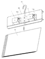
- FIG. 7 shows an example of a usage state suitable for use in a factory or the like.
- the two paper holders 1 are fixed to the plate-like body 60 by means such as screws at the overhang portions 13e formed on both sides of the back surface portion 13, respectively.
- a hanger 61 is attached to the plate-like body 60, and the hanger 61 can be used by being hooked at an appropriate place.
- Reference numeral 70 denotes paper.
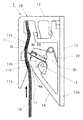
- FIG. 8 shows a state in which the paper 70 is inserted from the insertion port 17 in the direction indicated by the arrow in the drawing
- FIG. 8 shows a state in which the first sheet on the front side of the inserted paper 70 is pulled out. is there.
- a plurality of sheets (usually about 5 to 10 sheets) of papers 70 are appropriately stacked and inserted into the case 10 from the insertion port 17.
- the front end portion of the paper 70 hits the back portion 41 of the blade 40 lightly, and further, when the insertion is continued against the spring force of the elastic member 30 on the insertion port side with respect to the holding piece 20, the paper 70 becomes more internal. Enter.
- the substrate portion 21 of the holding piece 20 rotates about the shaft support portion 15 in the direction of the drawing arrow (insertion direction side).
- the class 70 is operated so as to be sandwiched between the front part 11.
- the distal end portion 43 of the blade 40 abuts on the paper located on the back side of the inserted paper 70 and is usually lightly stuck.
- the leading edge of the paper 70 is inserted to the tip of the rear slope 11c. Furthermore, after inserting in this way, the whole paper 70 is pulled down a little.
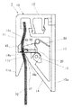
- the holding piece 20 returns to the pulling direction together with the spring force applied to the holding piece 20 and returns to the original state as shown in FIG. 9, and the paper 70 is entirely inserted into the front end portion 43 of the blade 40 and the front portion 11. Held between.
- the inner surface of the front portion 11 has a gentle negative gradient from the position in the vicinity of the insertion opening 17 (the upper end portion 14a of the inclined surface portion 14) toward the position in the vicinity of the tip portion 43 of the blade.
- a front inclined surface portion 11b and a rear inclined surface portion 11c having a gentle positive gradient from the position in the vicinity of the blade tip portion 43 toward the insertion direction of the paper 70 are formed.
- the inserted paper 70 is seen between the front slope part 11b and the rear slope part 11c (between the top part of the front slope part 11b and the top part of the rear slope part 11c).
- the pressing force of the distal end portion 43 of the blade 40 acts so as to bend like a bow that swells downward.
- the plurality of paper sheets 70 are reliably held as a whole because the frictional resistance between the paper sheets increases as compared with the case where the paper sheets 70 are not bent as described above. Therefore, in many cases, the paper holder 1 is used in the vertical direction. When the paper holder 1 is used in the vertical direction, the paper located on the back side or in the middle is prevented from falling off. In the case where the front slope portion 11b and the rear slope portion 11c are not present, the paper 70 is not bent as described above, and the paper is likely to fall off.
- the upper end of the inclined surface portion 14 is formed substantially parallel to the front inclined surface portion 11b, and when viewed from the side, the paper insertion port 17 is located in the vicinity of the distal end portion 43 of the blade when no paper is inserted. It is formed as a passage extending obliquely toward the position. For this reason, when paper is inserted into the case 10, the passage functions to guide the paper slightly obliquely from the back side to the front side, and contacts the back part 41 (and the tip part 43) of the blade 40. Since the corner is small, the resistance to the blade 40 is small, and paper can be smoothly inserted.
- the papers 70 are induced
- an inclined surface portion 14 is formed that extends substantially linearly from the lower end portion of the extended back surface portion 13c in the paper insertion direction, and is formed between the upper end portion 14a of the inclined surface portion 14 and the front portion 11. Since the paper insertion port 17 is formed, the paper 70 is smoothly and reliably guided to the insertion port 17 when the paper 70 is inserted.
- the paper is pulled out from the insertion port 17 in the direction indicated by the arrow as shown in FIG.
- the front end portion 43 of the blade 40 is pierced into the paper 70, and only the frontmost paper is pulled out. That is, only the foremost paper is pulled out while the other paper is held without dropping.
- the inner surface of the front portion 11 has a gentle negative gradient from the position in the vicinity of the insertion opening 17 (the upper end portion 14a of the inclined surface portion 14) toward the position in the vicinity of the tip portion 43 of the blade.
- a front inclined surface portion 11b and a rear inclined surface portion 11c having a gentle positive gradient from the position in the vicinity of the blade tip portion 43 toward the paper insertion direction are formed.
- the paper 70 is seen between the front slope part 11b and the rear slope part 11c (between the top part of the front slope part 11b and the top part of the rear slope part 11c).
- the pressing force of the distal end portion 43 of the blade 40 acts so as to bend like a bow that swells. Therefore, the plurality of paper sheets 70 increase the frictional resistance between the paper sheets, and are reliably held as a whole, and only the uppermost paper can be reliably pulled out.
- the paper holder 1 is used in the vertical direction. When the paper holder 1 is used in the vertical direction, it is possible to prevent the paper located on the back side or in the middle from dropping off together.
- the paper 70 is not bent as described above, and the paper is likely to fall off. Since the paper located on the frontmost side withdrawn is pulled out with the tip 43 of the blade 40 pierced, it reaches the front edge of the paper starting from the contact point where the tip 43 of the blade 40 is pierced. A straight, clean cutting line (trace) is formed. Further, due to the bending of the paper due to the presence of the rear slope portion 11c, the contact angle of the blade 40 with the cutting edge 44 when the paper 70 is pulled out is also smaller than when there is no rear slope portion 11c, so that the cutting is further performed. It is performed smoothly and a beautiful cutting line is obtained. By repeating the above operation, the paper located on the near side can be pulled out one by one easily and reliably.
Landscapes
- Sheet Holders (AREA)
Abstract
Description
そして、本出願人の出願に係る特許文献1には、「底面部を含む台部と、底面部と空間を隔ててほぼ平行に対向する上面部と該上面部の前端に側面視略U字状をなす前端正面部とを有する上覆部と、が着脱可能に係合し、一体化されて前記前端正面部の下方に紙類の挿入口が形成されるケースと、該ケース内に設けられた、挿入された紙類を保持するための保持片と、該保持片に対して前記紙類の引き抜き方向へバネ力を付勢する弾性部材と、前記保持片に設けられた刃とを備えてなり、前記保持片は、剛性を有する板状体からなり、前記前端正面部の内側に設けられた軸支部において回動可能に軸支され、前記軸支部から前記底面部側へ延びる基板部を備え、前記刃は、前記保持片に対して刃の垂直な起立状態を保持する刃固定部材に固定され、該刃固定部材は、前記基板部の紙類挿入方向側の面に、刃の先端部が前記基板部の前記底面部側の端部から突出するように設けられ、前記底面部の内面に、挿入された紙類の脱落を防止するための摩擦部を備えた、ペーパーホルダー。」が記載されている。
挿入口から挿入された紙類は、保持片に作用する弾性部材のバネ力によって、刃の先端部を挿入された紙類に突き刺した状態で、確実に保持され、保持された紙を手前側(正面部側)から1枚ずつ確実に引き抜くことができ、引き抜かれた紙には直線状の綺麗な引き裂き跡が残り、塵が発生しにくい。
また、背面部は、正面部の下側端部よりも下側に長く延びるように形成された延長背面部を備え、該延長背面部の下側端部から紙類の挿入方向へ向けて側面視ほぼ直線状に延びる傾斜面部を備えているため、紙類を挿入する際、紙類は円滑、確実に挿入口へと誘導され、使い勝手が優れる。
そして、正面部は透明性を有しており、複数の紙のうち、引き抜く順序が一番最初となる手前側(正面部側)となる紙と正面部との間には、保持片その他の部材が何ら介在していないため、保持された一番手前側の紙類の全面を、正面部を通して視認することができるため、使い勝手が優れる。
ペーパーホルダー1は、ケース10と、ケース10に内装される保持片2とを備えている。
ケース10は、正面部11と、正面部11と空間を隔ててほぼ平行に対向する背面部13と、正面部11と背面部13とを連結する上面部12とを備えており、上面部12は正面部と一体的に連設されており、正面部11及び上面部12と、背面部13という、二種の異なる断面を有する合成樹脂の成形品の組合せからなり、両者は着脱可能に係合し、一体化されるようになっている。そして、正面部11と背面部13との間に、下側から紙類を挿入するための挿入口17とが形成されている。
図2に示すように、背面部13の両側には、張出し部13eが設けられている。この張出し部13eは、後述するように、板材等にペーパーホルダー1を取り付けて使用する際の取付部として機能する。
ケース10の大きさは、限定されないが、一例として、正面方向から見て、その高さは3~6cm程度、奥行きは2~3cm程度、幅は4cm~7cm(背面部13の張出し部を含む。)程度のものが挙げられる。
上面部12と、背面部13の上部とが係止されて、両者が結合してケース10を形成している。
上面部12の内面には、背面部13側にある鉤状部12aからやや距離をおいて前後二段に突出した突出片12b,12cが形成されており、その先端の係止部12d,12eと、背面部13の上部の内面に前後二段に形成された係止部13a,13bとが互いに係止されて、一体化されている。
ケース10は、硬質の合成樹脂材からなり、正面部11と、該正面部11の上端に連設されて上面部12とが一体成形されたピースと、上面部12に形成された係止部12d,12eと着脱可能に係止されて一体化される背面部13とで構成されており、正面部11を背面部13に対し、横方向にスライドさせることにより、分離可能である。
そして、ケース10の少なくとも正面部11は透明性を有しており、正面部11の内側を視認することができる。
そして、該延長背面部13cの下側端部から、側面視ほぼV字状に、紙類の挿入方向(ケース10の上方)へ向けて側面視ほぼ直線状に延びる傾斜面部14が形成されている。傾斜面部14の上方端部14aと正面部11との間に紙類の挿入口17が形成されている。
傾斜面部14の上方端部14a寄りの内側には、後述する保持片20が軸支されるための軸支部15が、傾斜面部14からその内方空間(背面部13と傾斜面部14との間の空間)に突出するように形成されている。軸支部15は、傾斜面部14の横幅より短い横幅を有するように形成されており、軸支部15には、シャフト(図示省略)を挿通可能な孔が横方向(ケースの幅方向)に形成されている(図3参照)。
前方斜面部11b及び後方斜面部11cの各勾配(傾斜角)は6~20°、前方斜面部11b及び後方斜面部11cそれぞれの高低差(紙類が未挿入の状態における刃の先端部43が位置する正面部11の内面のレベルを基準とした各斜面部頂部までの高さ)は0.8~3mm、さらには、前方斜面部11b及び後方斜面部11cそれぞれの長さは4~10mm、前方斜面部11bの頂部と後方斜面部11cの頂部との間の長さは12~22mmの範囲が、紙類の挿入のし易さと脱落のしにくさの二点の両立をより的確にする観点から好ましい。
前方斜面部11bと後方斜面部11cを形成することによって、正面部11の内面に、側面視、全体として緩やかな湾曲を呈する凹部が形成され、前方斜面部11bの頂部と後方斜面部11cの頂部との間(中間部)に、刃の先端部43が位置している。前方斜面部11bと後方斜面部11cは側面視、直線状のほか、緩やかな曲線で弓なり又は弧状となるように形成してもよい。刃の先端部43が位置する、前方斜面部11bと後方斜面部11cとの間に形成された、正面部側に向けての凹部は、刃の先端部43の動作に支障を来たさないためのものである。
保持片20は、ケース10の内部に設けられた軸支部15において回動可能に軸支されており、かつ紙類の引き抜き方向へ弾性部材30によってバネ力が付勢されている。そして、該保持片20には、その端部(正面部側の端部)から刃40の先端部43が正面部11に向かって突出するように刃40が設けられている。
保持片20は、例えば、図3に示すように、折り曲げ加工された、所要の剛性を有する板状体からなり、傾斜面部14の内側に設けられた軸支部15において回動可能に軸支され、軸支部15から正面部11側へ延びる基板部21を備えている。
保持片20は、剛性を有する板状体からなるため、板状体の加工等により簡単に製作できる。保持片20は、例えば、厚さ0.1~0.3mm程度のSK材、ステンレス鋼材等の金属板で形成し得る。保持片20の横幅は、一例として2~4cm程度である。
保持片20は、側面視略くの字状に屈曲され、基板部21に連なる取付け面部22を備え、基板部21と取付け面部22とがアール状に交わる屈曲部近傍において軸支部15に軸支されている。
保持片20は、傾斜面部14の内側に設けられた軸支部15において回動可能に軸支され、軸支部15から正面部11側へ延びる基板部21を備えているため、正面部11と背面部13とに形成される空間を最大限に有効に利用して保持片20が配置されており、物品の大型化を招くことがなく、また、限られた狭い空間内で保持片20(及び刃)の回動半径を大きくとることができ、紙類の挿入、引き抜きに際し、保持片20の円滑で安定した動作が確保される。
また、保持片20の基板部21の左右両端には、後述する刃固定部材50を所定位置(横方向)にセットするための係止部28が連設されている。
折り曲げ部26の幅方向の中央部には刃固定部材50に固定された刃が挿通するスリット26aが形成されている。折り曲げ部26及び係止部27は、後述する刃固定部材50の縦方向の位置決め部となり、スリット26a及び係止部28は、刃40が設けられた刃固定部材50の横方向の位置決め部となる。スリット26aを通って、基板部21の底面部側の端部から刃40の先端部43が突出する。
弾性部材30は、保持片20に対して紙類の引き抜き方向へバネ力を付勢する。
本実施例では、図1,4に示すようにコイルばねを用いている。コイルばね30の線材の両端は接線方向に突出しており、その一方端部が後述する刃固定部材50に設けた孔に差し込まれるとともに、他方端部が背面部13の内面に当接しており、これにより、保持片20に対してバネ力が付勢されるようにしている。
刃40は、カッターナイフの刃に使われる炭素工具鋼(SK)など、鋼製のものが好適に用いられる。その厚さは、通常、0.3~1.2mm程度である。
図5に示すように、刃40は、直線状に延びる背部41と、該背部41と交差して鋭角状の刃の先端部(ポイント)43を形成する刃先(エッジ)44と、背部41と対向する位置にある刃元45(刃先44の根元)と、この刃元45の近傍から背部41に向けて傾斜して伸びる傾斜辺部46とを有している。この傾斜辺部46の傾斜角βはほぼ30~60°の範囲である。刃40の先端部43の角度は、通常20~40°程度である。刃40の刃先44の長さは、一例として5~10mm程度である。
刃40は、交差して鋭角状の刃の先端部43を形成する背部41と刃先44、と、刃元45の近傍から背部41に向けて傾斜して延びるにように形成された傾斜辺部46とを有する形状であるため、ケース1の狭い内部空間に刃40が合理的に配置され、刃40を含む保持片20の動きがケース1によって干渉されることなく、刃40及び保持片20が確実に動作する。
刃固定部材50は、刃40を固定し、所定位置に保持するとともに、保持片20の基板部21に装着される部材である。刃固定部材50には、刃40の先端部43が突出するように刃40が設けられる。また、刃40は、基板部21の面に対して刃40の垂直な起立状態を保持するように刃固定部材50に固定される。
図6に示すように、刃固定部材50は、保持片20の基板部21に固定される平面部(底面部)51を備えたベース部52と、該ベース部52から垂直に起立し、刃40の腹部(平)の両サイドで腹部を保持する、刃40を収容固定するための起立部53とを有する。起立部53は、刃40の高さに適合する高さを有する。この起立部53には刃40の輪郭に沿うスリット54が形成されており、このスリット54に刃40を挿入、固定して、刃40のベース部52に対する垂直状態が保持される。刃固定部材50は、合成樹脂の成形品により構成し得る。
刃固定部材は、保持片20に固定可能なベース部52と、該ベース部52から垂直に起立し、刃の腹部を両サイドで保持する起立部53とを有するため、刃固定部材50の構成が簡易であり、製作コストも低廉である。
刃40は、保持片20に対して刃の垂直な起立状態を保持する刃固定部材50に固定され、刃固定部材50は、基板部21の紙類挿入方向側の面に、刃40の先端部が基板部21の正面部11側の端部(スリット26a)から突出するように設けられているため、刃は所定の位置、向きに刃固定部材50によって確実に保持されるとともに、刃固定部材50を用いた保持片20に対する取付け、組立てが簡単である。
このとき、刃40は、交差して鋭角状の刃の先端部43を形成する背部41と刃先44と、刃元45の近傍から背部41に向けて傾斜して伸びる傾斜辺部46とを有するため、ケースの狭い内部空間に刃40が合理的に配置され、基板部21の動きに伴い刃の動きが支障を来たすことがなく(背部41に対向する側が背面部13の係止部13a等に突き当たることがなく)、刃40を含む保持片20が確実に動作する。
したがって、刃固定部材50は、保持片20の基板部21の所定位置に確実、簡単に装着可能である。
なお、上記のほか、刃固定部材50の基板部21への固定は、両面粘着テープ、接着剤、その他の適宜固定手段を用いることができる。
また、刃40の背部41は、保持片20の基板部21に沿っており、紙類挿入方向に向けてやや傾斜して配置されているため、紙類の挿入も容易に行われる。
ペーパーホルダー1の設置方向、設置場所、設置手段は限定されない。ケース10の裏面(正面部11の外面)に粘着テープ等を張って、各種壁部に設置することができる。保持すべき紙類のサイズに応じて、ペーパーホルダー1を横長の板体等に横に複数個並べて設置し、使用することもできる。図7に工場等での使用に適した、使用状態の一例を示す。
2個のペーパーホルダー1は、夫々、背面部13の両側に形成された張出し部13eにおいて板状体60にビス止め等の手段により固定されている。板状体60にはハンガー61が装着されており、該ハンガー61を適宜箇所に掛止して使用することができる。符号70は紙類を示す。
ペーパーホルダー1の動作について、図8、図9を参照して説明する。
図8は、紙類70を挿入口17から図の矢印に示す方向に挿入した状態を示し、図8は、挿入した紙類70の一番手前側の一枚の紙を引き抜く状態を示すものである。
図8に示すように、先ず、適宜複数枚(通常、5~10枚程度)の紙類70を重ねた状態で、挿入口17からケース10の内部へ挿入する。すると、紙類70の前端部は刃40の背部41に軽く当り、さらに保持片20に対する挿入口側への弾性部材30によるバネ力に抗して挿入を続けると、紙類70は、より内部へ進入する。この時、保持片20の基板部21は、軸支部15を支点として、図面矢印の方向(挿入方向側)に回動し、保持片20にかかるバネ力は、刃40の先端部43が紙類70を、正面部11との間で挟持するように働く。刃40の先端部43は、挿入された紙類70の背面部側に位置する紙に当接し、通常、軽く刺さった状態となる。紙類70の先端は後方斜面部11cの先まで挿入される。
さらに、このように挿し込んだ後、紙類70を全体を下方へ若干引く。保持片20はそれにかかるバネ力と共に引かれた方向へ戻り、図9に示すとおり、元の状態に戻り、紙類70は、その全体が刃40の先端部43に刺された状態で正面部11との間に保持される。
ここで、前記のとおり、正面部11の内面には、挿入口17近傍の位置(傾斜面部14の上方端部14a)から刃の先端部43近傍の位置に向けて緩やかな負の勾配となる前方斜面部11bと、刃の先端部43近傍の位置から、紙類70の挿入方向に向けて緩やかな正の勾配となる後方斜面部11cとが形成されている。このため、挿入された紙類70が、図示のように、前方斜面部11bと後方斜面部11cとの間(前方斜面部11bの頂部と後方斜面部11cの頂部との間)において、側面視、下方に膨らむ弓なりに撓むように刃40の先端部43の押圧力が働く。それゆえ、複数枚の紙類70は、上記のような紙類70の撓みがない場合に比べて各紙葉同士の摩擦抵抗が増大し、全体として、確実に保持される。したがって、ペーパーホルダー1は縦向きに使用される場合が多いところ、そのように縦向きに使用する場合にあって、背面部側や中間に位置する紙が脱落することが防がれる。前方斜面部11bと後方斜面部11cとが存在しない場合では、上記のような紙類70の撓みは生じないので、紙の脱落が生じやすい。
また、前記のとおり、傾斜面部14の上端は、前方斜面部11bとほぼ平行に形成され、側面視、紙類の挿入口17が、紙類が未挿入の状態における刃の先端部43近傍の位置に向けて斜状に延びる通路として形成されている。このため、紙類をケース10の内部へ挿入する際、該通路が紙類を背面側から正面側へとやや斜めに誘導する機能を奏し、刃40の背部41(及び先端部43)に対する接触角が小さくなるため、刃40に対する抵抗が小となり、紙類をスムーズに挿入することができる。また、前方斜面部11b及び後方斜面部11cは緩やかな勾配に形成されているため、これに沿うように紙類70は誘導され、スムーズに挿入、引き抜きできる。
さらに、延長背面部13cの下側端部から紙類の挿入方向へ向けて側面視ほぼ直線状に延びる傾斜面部14が形成され、傾斜面部14の上方端部14aと正面部11との間に紙類の挿入口17が形成されているため、紙類70を挿入する際、紙類70は円滑、確実に挿入口17へと誘導される。
ここで、前記のとおり、正面部11の内面には、挿入口17近傍の位置(傾斜面部14の上方端部14a)から刃の先端部43近傍の位置に向けて緩やかな負の勾配となる前方斜面部11bと、刃の先端部43近傍の位置から、紙類の挿入方向に向けて緩やかな正の勾配となる後方斜面部11cとが形成されている。このため、紙類70が、図示のように、前方斜面部11bと後方斜面部11cとの間(前方斜面部11bの頂部と後方斜面部11cの頂部との間)において、側面視、手前側に膨らむ弓なりに撓むように刃40の先端部43の押圧力が働く。それゆえ、複数枚の紙類70は、各紙葉同士の摩擦抵抗が増大し、全体として、確実に保持され、一番上の紙のみを確実に引き抜くことができる。ペーパーホルダー1は縦向きに使用される場合が多いところ、そのように縦向きに使用する場合にあって、背面部側や中間に位置する紙も一緒に脱落することが防がれる。前方斜面部11bと後方斜面部11cとが存在しない場合では、上記のような紙類70の撓みは生じないので、紙の脱落が生じやすい。
引き抜かれた一番手前側に位置する紙は、刃40の先端部43が突き刺さった状態で引き抜かれることになるので、刃40の先端部43が突き刺さった接触点を始点として紙の前端側に至る直線状の綺麗な切断線(跡)が形成される。また、後方斜面部11cの存在による紙類の撓みによって、紙類70を引き抜くときの刃40の刃先44との接触角も、後方斜面部11cがない場合に比べて小さくなるので、切断がよりスムーズに行なわれ、綺麗な切断線が得られる。
上記動作を繰り返すことによって、簡単かつ確実に手前側に位置する紙を1枚ずつ引き抜くことができる。
10 ケース
11 正面部
12 上面部
13 背面部
13c 延長背面部
14 傾斜面部
15 軸支部
17 挿入口
20 保持片
30 弾性部材
40 刃
43 刃の先端部
70 紙類
Claims (1)
- 正面部と、該正面部と空間を隔ててほぼ平行に対向する背面部と、前記正面部と前記背面部とを連結する上面部と、前記正面部と前記背面部との間に、下側から紙類を挿入するための挿入口とを備えたケースと、前記ケースの内部に設けられた軸支部において回動可能に軸支され、かつ前記紙類の引き抜き方向へバネ力が付勢された保持片であって、その端部から前記正面部に向かって突出するように刃が設けられた保持片とを備え、前記刃の先端部を、前記挿入口から挿入された紙類に当接させて紙類を保持するように構成した、ペーパーホルダーであって、前記背面部は、前記正面部の下側端部よりも下側に長く延びるように形成された延長背面部を備え、該延長背面部の下側端部から前記紙類の挿入方向へ向けて側面視ほぼ直線状に延びる傾斜面部を備え、前記軸支部は、前記傾斜面部の内側に設けられ、前記正面部は透明性を有してなる、ペーパーホルダー。
Priority Applications (6)
| Application Number | Priority Date | Filing Date | Title |
|---|---|---|---|
| KR1020147029454A KR20140145166A (ko) | 2012-03-22 | 2013-03-06 | 페이퍼 홀더 |
| CN201380015090.5A CN104203590B (zh) | 2012-03-22 | 2013-03-06 | 夹纸器 |
| CA2866443A CA2866443A1 (en) | 2012-03-22 | 2013-03-06 | Paper holder |
| EP13763446.5A EP2829412B1 (en) | 2012-03-22 | 2013-03-06 | Paper holder |
| US14/383,190 US9469147B2 (en) | 2012-03-22 | 2013-03-06 | Paper holder |
| IN1696MUN2014 IN2014MN01696A (ja) | 2012-03-22 | 2014-08-22 |
Applications Claiming Priority (2)
| Application Number | Priority Date | Filing Date | Title |
|---|---|---|---|
| JP2012-066413 | 2012-03-22 | ||
| JP2012066413A JP5551199B2 (ja) | 2012-03-22 | 2012-03-22 | ペーパーホルダー |
Publications (1)
| Publication Number | Publication Date |
|---|---|
| WO2013141093A1 true WO2013141093A1 (ja) | 2013-09-26 |
Family
ID=49222553
Family Applications (1)
| Application Number | Title | Priority Date | Filing Date |
|---|---|---|---|
| PCT/JP2013/056876 Ceased WO2013141093A1 (ja) | 2012-03-22 | 2013-03-06 | ペーパーホルダー |
Country Status (8)
| Country | Link |
|---|---|
| US (1) | US9469147B2 (ja) |
| EP (1) | EP2829412B1 (ja) |
| JP (1) | JP5551199B2 (ja) |
| KR (1) | KR20140145166A (ja) |
| CN (1) | CN104203590B (ja) |
| CA (1) | CA2866443A1 (ja) |
| IN (1) | IN2014MN01696A (ja) |
| WO (1) | WO2013141093A1 (ja) |
Citations (7)
| Publication number | Priority date | Publication date | Assignee | Title |
|---|---|---|---|---|
| JP3008170U (ja) * | 1994-08-23 | 1995-03-07 | 株式会社伊東屋 | クリップと該クリップを用いたクリップファイル並びに用箋鋏 |
| JP3775222B2 (ja) * | 2000-08-07 | 2006-05-17 | エヌエスプランニング株式会社 | カードホルダー |
| WO2008096463A1 (ja) * | 2007-02-06 | 2008-08-14 | Ns Planning Inc. | ペーパーホルダー |
| WO2009116190A1 (ja) * | 2008-03-21 | 2009-09-24 | エヌエスプランニング株式会社 | ペーパーホルダー |
| WO2010073812A1 (ja) * | 2008-12-25 | 2010-07-01 | エヌエスプランニング株式会社 | ペーパーホルダー |
| WO2011077794A1 (ja) * | 2009-12-24 | 2011-06-30 | エヌエスプランニング株式会社 | ペーパーホルダー |
| JP2012121203A (ja) * | 2010-12-07 | 2012-06-28 | Ns Planning Kk | ペーパーホルダー |
Family Cites Families (41)
| Publication number | Priority date | Publication date | Assignee | Title |
|---|---|---|---|---|
| US2234086A (en) * | 1939-06-15 | 1941-03-04 | Rosebraugh Walter | Folio lyre |
| US2371713A (en) * | 1943-06-29 | 1945-03-20 | Prec Engineering Company Ltd | Card index |
| US2486253A (en) * | 1946-05-23 | 1949-10-25 | Louis L Bresler | Desk pad |
| US2607070A (en) * | 1950-10-06 | 1952-08-19 | Ralph D Wertz | Fish and game cleaning device |
| US3065668A (en) * | 1954-12-22 | 1962-11-27 | Leybourn Specialties Inc | Map holder and viewing device |
| NL292174A (ja) * | 1963-05-01 | |||
| US3212146A (en) * | 1963-10-02 | 1965-10-19 | Thomas P Morgan | Holder for pencils, pens and similar long articles |
| US3425389A (en) * | 1967-08-28 | 1969-02-04 | Gloria C Sacco | Place marker aid |
| US3560092A (en) * | 1968-07-24 | 1971-02-02 | L J Coney | Clipboard with slate surface |
| US3639020A (en) * | 1968-11-22 | 1972-02-01 | Sydney M Nesbitt | Suspension file |
| US3828402A (en) * | 1973-04-16 | 1974-08-13 | W Gorman | Device for releasable gripping article |
| JPS5521185Y2 (ja) * | 1975-03-28 | 1980-05-21 | ||
| US4241477A (en) * | 1979-08-16 | 1980-12-30 | John Freedom | Paper clip |
| US4253216A (en) * | 1979-12-03 | 1981-03-03 | James Brown | Tag and note clip |
| JPS6029669U (ja) * | 1983-08-03 | 1985-02-28 | 共同印刷株式会社 | ペ−パ−ホルダ− |
| DE3636640A1 (de) * | 1986-10-28 | 1988-05-11 | Licinvest Ag | Bildwechsler |
| JPS6416375U (ja) * | 1987-07-18 | 1989-01-26 | ||
| US5193795A (en) * | 1987-11-21 | 1993-03-16 | Licinvest Ag | Device for the cyclic rearrangement of a pile of sheets |
| JPH0271680U (ja) * | 1988-11-21 | 1990-05-31 | ||
| EP0438895B1 (en) * | 1990-01-20 | 1994-03-16 | OHTO KABUSHIKI KAISHA (also known as Ohto Co., Ltd) | One-action paper clip |
| US5112083A (en) * | 1990-08-22 | 1992-05-12 | All-State Legal Supply Co. | Paper pad construction and clip means therefor |
| US5305501A (en) * | 1993-03-01 | 1994-04-26 | Ockba Ali M A | Spring clip |
| JPH07314965A (ja) * | 1994-05-30 | 1995-12-05 | Kenji Tsuge | ペーパーホルダ |
| JP3726167B2 (ja) * | 1994-07-13 | 2005-12-14 | 哲正 黒田 | ホルダ |
| JPH09220893A (ja) * | 1996-02-16 | 1997-08-26 | Tetsumasa Kuroda | ホルダ |
| JP3085201B2 (ja) * | 1996-07-30 | 2000-09-04 | トヨタ自動車株式会社 | 書類保持具 |
| JP2804017B2 (ja) * | 1996-10-09 | 1998-09-24 | 東京金属工業株式会社 | 紙挟み |
| JP2000062370A (ja) * | 1998-08-17 | 2000-02-29 | Kenji Yokoyama | シート保持具 |
| US6367761B1 (en) * | 2000-05-09 | 2002-04-09 | Hiromori Inc. | Paper holder |
| CN1194868C (zh) * | 2000-12-28 | 2005-03-30 | Ns设计公司 | 卡夹 |
| US7076899B2 (en) * | 2001-03-28 | 2006-07-18 | Rose Displays, Ltd | Extruded grip frame arrangement |
| US6470536B1 (en) * | 2001-06-11 | 2002-10-29 | Jason Todd Kettlestrings | Clip board with improved retention means |
| US6578811B1 (en) * | 2002-01-02 | 2003-06-17 | Hiromori Inc. | Paper holder |
| US6681452B1 (en) * | 2002-09-27 | 2004-01-27 | Adstracts, Inc. | Clamping apparatus with removable attachments |
| JP2005066859A (ja) * | 2003-08-26 | 2005-03-17 | Toshio Kaneshiro | クリップ |
| ITTO20030731A1 (it) * | 2003-09-23 | 2005-03-24 | Fiat Auto Spa | Fermacarte, particolarmente per autoveicoli |
| US7874758B2 (en) * | 2004-10-22 | 2011-01-25 | Lihit Lab., Inc. | Binding device |
| CN100491135C (zh) * | 2005-08-01 | 2009-05-27 | 利高文具制造厂有限公司 | 带开夹手柄的线板夹 |
| US7614598B2 (en) * | 2007-04-04 | 2009-11-10 | Smith David C | Apparatus for retaining sheets against a back surface |
| US8425139B2 (en) * | 2009-11-02 | 2013-04-23 | Stephen Kwok Ki Chan | Sheet holder and edge pattern making apparatus incorporating the same |
| US8876165B1 (en) * | 2013-05-10 | 2014-11-04 | Hege Innovations, Inc. | Clipboard with mounting accessories |
-
2012
- 2012-03-22 JP JP2012066413A patent/JP5551199B2/ja not_active Expired - Fee Related
-
2013
- 2013-03-06 WO PCT/JP2013/056876 patent/WO2013141093A1/ja not_active Ceased
- 2013-03-06 CA CA2866443A patent/CA2866443A1/en not_active Abandoned
- 2013-03-06 CN CN201380015090.5A patent/CN104203590B/zh not_active Expired - Fee Related
- 2013-03-06 EP EP13763446.5A patent/EP2829412B1/en not_active Not-in-force
- 2013-03-06 KR KR1020147029454A patent/KR20140145166A/ko not_active Withdrawn
- 2013-03-06 US US14/383,190 patent/US9469147B2/en not_active Expired - Fee Related
-
2014
- 2014-08-22 IN IN1696MUN2014 patent/IN2014MN01696A/en unknown
Patent Citations (8)
| Publication number | Priority date | Publication date | Assignee | Title |
|---|---|---|---|---|
| JP3008170U (ja) * | 1994-08-23 | 1995-03-07 | 株式会社伊東屋 | クリップと該クリップを用いたクリップファイル並びに用箋鋏 |
| JP3775222B2 (ja) * | 2000-08-07 | 2006-05-17 | エヌエスプランニング株式会社 | カードホルダー |
| WO2008096463A1 (ja) * | 2007-02-06 | 2008-08-14 | Ns Planning Inc. | ペーパーホルダー |
| WO2009116190A1 (ja) * | 2008-03-21 | 2009-09-24 | エヌエスプランニング株式会社 | ペーパーホルダー |
| WO2010073812A1 (ja) * | 2008-12-25 | 2010-07-01 | エヌエスプランニング株式会社 | ペーパーホルダー |
| WO2011077794A1 (ja) * | 2009-12-24 | 2011-06-30 | エヌエスプランニング株式会社 | ペーパーホルダー |
| JP2011131502A (ja) | 2009-12-24 | 2011-07-07 | Ns Planning Kk | ペーパーホルダー |
| JP2012121203A (ja) * | 2010-12-07 | 2012-06-28 | Ns Planning Kk | ペーパーホルダー |
Also Published As
| Publication number | Publication date |
|---|---|
| JP2013193451A (ja) | 2013-09-30 |
| EP2829412B1 (en) | 2017-06-21 |
| CA2866443A1 (en) | 2013-09-26 |
| JP5551199B2 (ja) | 2014-07-16 |
| US9469147B2 (en) | 2016-10-18 |
| EP2829412A1 (en) | 2015-01-28 |
| CN104203590B (zh) | 2016-03-16 |
| KR20140145166A (ko) | 2014-12-22 |
| US20150026929A1 (en) | 2015-01-29 |
| CN104203590A (zh) | 2014-12-10 |
| EP2829412A4 (en) | 2015-12-09 |
| IN2014MN01696A (ja) | 2015-05-29 |
Similar Documents
| Publication | Publication Date | Title |
|---|---|---|
| JP4826954B2 (ja) | ペーパーホルダー | |
| US20090302084A1 (en) | Adhesive tape cutter | |
| JP4880028B2 (ja) | ペーパーホルダー | |
| JP5551199B2 (ja) | ペーパーホルダー | |
| JP2017036147A (ja) | 分割貼りもできるテープカッター | |
| WO2009116190A1 (ja) | ペーパーホルダー | |
| WO2010073812A1 (ja) | ペーパーホルダー | |
| JP2012121203A (ja) | ペーパーホルダー | |
| JP3187187U (ja) | 移動式クリップボード | |
| JP3174332U (ja) | 外れ防止ロック機能付紙脚 | |
| JP3155456U (ja) | トイレットペーパー収納具 | |
| JP2015043850A (ja) | ロールペーパー双対切断装置 | |
| JP3130835U (ja) | 輪ゴムホルダ | |
| KR200454002Y1 (ko) | 디스플레이장치 거치용 커버 | |
| JP4378469B2 (ja) | 綴じ部材 | |
| JP2019199075A (ja) | ペーパーホルダー | |
| KR100910181B1 (ko) | 메모지 모듈 | |
| KR20100002684U (ko) | 테입 홀더 | |
| JP2013081728A (ja) | 1枚だけで切れるカッタ−補助器 | |
| JP2006280667A (ja) | トイレットペーパーホルダー用架設板 | |
| JP2019051056A (ja) | 切断用工具 | |
| JP2010131836A (ja) | バインダーの綴じ具 | |
| JP2015110436A (ja) | 物品収納ケースの取付け具 | |
| JP2007045489A (ja) | ラップフィルム巻物収納箱 | |
| JP2007269379A (ja) | ブリスターパッケージ |
Legal Events
| Date | Code | Title | Description |
|---|---|---|---|
| WWE | Wipo information: entry into national phase |
Ref document number: 201380015090.5 Country of ref document: CN |
|
| 121 | Ep: the epo has been informed by wipo that ep was designated in this application |
Ref document number: 13763446 Country of ref document: EP Kind code of ref document: A1 |
|
| ENP | Entry into the national phase |
Ref document number: 2866443 Country of ref document: CA |
|
| WWE | Wipo information: entry into national phase |
Ref document number: 14383190 Country of ref document: US |
|
| REEP | Request for entry into the european phase |
Ref document number: 2013763446 Country of ref document: EP |
|
| WWE | Wipo information: entry into national phase |
Ref document number: 2013763446 Country of ref document: EP |
|
| ENP | Entry into the national phase |
Ref document number: 20147029454 Country of ref document: KR Kind code of ref document: A |
|
| WWE | Wipo information: entry into national phase |
Ref document number: IDP00201406401 Country of ref document: ID |
|
| NENP | Non-entry into the national phase |
Ref country code: DE |