WO2013141220A1 - 燃料タンク用弁装置 - Google Patents
燃料タンク用弁装置 Download PDFInfo
- Publication number
- WO2013141220A1 WO2013141220A1 PCT/JP2013/057730 JP2013057730W WO2013141220A1 WO 2013141220 A1 WO2013141220 A1 WO 2013141220A1 JP 2013057730 W JP2013057730 W JP 2013057730W WO 2013141220 A1 WO2013141220 A1 WO 2013141220A1
- Authority
- WO
- WIPO (PCT)
- Prior art keywords
- arc
- elastic piece
- case
- float body
- fuel tank
- Prior art date
- Legal status (The legal status is an assumption and is not a legal conclusion. Google has not performed a legal analysis and makes no representation as to the accuracy of the status listed.)
- Ceased
Links
Images





Classifications
-
- F—MECHANICAL ENGINEERING; LIGHTING; HEATING; WEAPONS; BLASTING
- F16—ENGINEERING ELEMENTS AND UNITS; GENERAL MEASURES FOR PRODUCING AND MAINTAINING EFFECTIVE FUNCTIONING OF MACHINES OR INSTALLATIONS; THERMAL INSULATION IN GENERAL
- F16K—VALVES; TAPS; COCKS; ACTUATING-FLOATS; DEVICES FOR VENTING OR AERATING
- F16K24/00—Devices, e.g. valves, for venting or aerating enclosures
- F16K24/04—Devices, e.g. valves, for venting or aerating enclosures for venting only
- F16K24/042—Devices, e.g. valves, for venting or aerating enclosures for venting only actuated by a float
-
- F—MECHANICAL ENGINEERING; LIGHTING; HEATING; WEAPONS; BLASTING
- F16—ENGINEERING ELEMENTS AND UNITS; GENERAL MEASURES FOR PRODUCING AND MAINTAINING EFFECTIVE FUNCTIONING OF MACHINES OR INSTALLATIONS; THERMAL INSULATION IN GENERAL
- F16K—VALVES; TAPS; COCKS; ACTUATING-FLOATS; DEVICES FOR VENTING OR AERATING
- F16K24/00—Devices, e.g. valves, for venting or aerating enclosures
- F16K24/04—Devices, e.g. valves, for venting or aerating enclosures for venting only
- F16K24/042—Devices, e.g. valves, for venting or aerating enclosures for venting only actuated by a float
- F16K24/044—Devices, e.g. valves, for venting or aerating enclosures for venting only actuated by a float the float being rigidly connected to the valve element, the assembly of float and valve element following a substantially translational movement when actuated, e.g. also for actuating a pilot valve
-
- F—MECHANICAL ENGINEERING; LIGHTING; HEATING; WEAPONS; BLASTING
- F16—ENGINEERING ELEMENTS AND UNITS; GENERAL MEASURES FOR PRODUCING AND MAINTAINING EFFECTIVE FUNCTIONING OF MACHINES OR INSTALLATIONS; THERMAL INSULATION IN GENERAL
- F16K—VALVES; TAPS; COCKS; ACTUATING-FLOATS; DEVICES FOR VENTING OR AERATING
- F16K27/00—Construction of housing; Use of materials therefor
- F16K27/02—Construction of housing; Use of materials therefor of lift valves
-
- B—PERFORMING OPERATIONS; TRANSPORTING
- B60—VEHICLES IN GENERAL
- B60K—ARRANGEMENT OR MOUNTING OF PROPULSION UNITS OR OF TRANSMISSIONS IN VEHICLES; ARRANGEMENT OR MOUNTING OF PLURAL DIVERSE PRIME-MOVERS IN VEHICLES; AUXILIARY DRIVES FOR VEHICLES; INSTRUMENTATION OR DASHBOARDS FOR VEHICLES; ARRANGEMENTS IN CONNECTION WITH COOLING, AIR INTAKE, GAS EXHAUST OR FUEL SUPPLY OF PROPULSION UNITS IN VEHICLES
- B60K15/00—Arrangement in connection with fuel supply of combustion engines or other fuel consuming energy converters, e.g. fuel cells; Mounting or construction of fuel tanks
- B60K15/03—Fuel tanks
- B60K15/035—Fuel tanks characterised by venting means
- B60K15/03519—Valve arrangements in the vent line
-
- F—MECHANICAL ENGINEERING; LIGHTING; HEATING; WEAPONS; BLASTING
- F02—COMBUSTION ENGINES; HOT-GAS OR COMBUSTION-PRODUCT ENGINE PLANTS
- F02M—SUPPLYING COMBUSTION ENGINES IN GENERAL WITH COMBUSTIBLE MIXTURES OR CONSTITUENTS THEREOF
- F02M25/00—Engine-pertinent apparatus for adding non-fuel substances or small quantities of secondary fuel to combustion-air, main fuel or fuel-air mixture
- F02M25/08—Engine-pertinent apparatus for adding non-fuel substances or small quantities of secondary fuel to combustion-air, main fuel or fuel-air mixture adding fuel vapours drawn from engine fuel reservoir
- F02M25/0836—Arrangement of valves controlling the admission of fuel vapour to an engine, e.g. valve being disposed between fuel tank or absorption canister and intake manifold
-
- F—MECHANICAL ENGINEERING; LIGHTING; HEATING; WEAPONS; BLASTING
- F02—COMBUSTION ENGINES; HOT-GAS OR COMBUSTION-PRODUCT ENGINE PLANTS
- F02M—SUPPLYING COMBUSTION ENGINES IN GENERAL WITH COMBUSTIBLE MIXTURES OR CONSTITUENTS THEREOF
- F02M37/00—Apparatus or systems for feeding liquid fuel from storage containers to carburettors or fuel-injection apparatus; Arrangements for purifying liquid fuel specially adapted for, or arranged on, internal-combustion engines
- F02M37/20—Apparatus or systems for feeding liquid fuel from storage containers to carburettors or fuel-injection apparatus; Arrangements for purifying liquid fuel specially adapted for, or arranged on, internal-combustion engines characterised by means for preventing vapour lock
-
- Y—GENERAL TAGGING OF NEW TECHNOLOGICAL DEVELOPMENTS; GENERAL TAGGING OF CROSS-SECTIONAL TECHNOLOGIES SPANNING OVER SEVERAL SECTIONS OF THE IPC; TECHNICAL SUBJECTS COVERED BY FORMER USPC CROSS-REFERENCE ART COLLECTIONS [XRACs] AND DIGESTS
- Y10—TECHNICAL SUBJECTS COVERED BY FORMER USPC
- Y10T—TECHNICAL SUBJECTS COVERED BY FORMER US CLASSIFICATION
- Y10T137/00—Fluid handling
- Y10T137/0753—Control by change of position or inertia of system
- Y10T137/0874—Vent opening or closing on tipping container
-
- Y—GENERAL TAGGING OF NEW TECHNOLOGICAL DEVELOPMENTS; GENERAL TAGGING OF CROSS-SECTIONAL TECHNOLOGIES SPANNING OVER SEVERAL SECTIONS OF THE IPC; TECHNICAL SUBJECTS COVERED BY FORMER USPC CROSS-REFERENCE ART COLLECTIONS [XRACs] AND DIGESTS
- Y10—TECHNICAL SUBJECTS COVERED BY FORMER USPC
- Y10T—TECHNICAL SUBJECTS COVERED BY FORMER US CLASSIFICATION
- Y10T137/00—Fluid handling
- Y10T137/2931—Diverse fluid containing pressure systems
- Y10T137/3003—Fluid separating traps or vents
- Y10T137/3084—Discriminating outlet for gas
- Y10T137/309—Fluid sensing valve
- Y10T137/3099—Float responsive
Definitions
- the present invention relates to an improvement of a valve device that is attached to a fuel tank of an automobile or a two-wheeled vehicle and functions to communicate between the inside and outside of the tank when the valve is open.
- a support portion of the cantilever float valve body is formed by a slit formed in the bottom portion of the housing constituting the fuel tank, and the impact energy when the float valve body is lowered is supported by the support portion. Some of them are absorbed by bending.
- the slit is formed so as to be parallel to the tangent of this circle of the housing having a circular cross section (see FIG. 2A of Patent Document 2).
- the main problem to be solved by the present invention is that in this type of valve, the total length of the elastic piece that abuts and elastically deforms the bottom of the float body to absorb the impact energy of the descent when the float body is lowered, This is to ensure as large as possible without complicating the structure of the valve.
- a valve device for a fuel tank is used by being attached to a fuel tank, A case with a vent valve port in the upper part that communicates with the outside of the tank, and a fuel inflow part below it; A float body that is in the case and is raised by the fuel flowing into the case and seated on the vent valve port; A first arc-shaped dividing groove formed on the surface portion facing the bottom of the float body in the case so that the center side of the surface portion is a curved inner side, and the outer surface of the first arc-shaped dividing groove.
- the elastic piece is formed by the second arc-shaped dividing groove formed so that the center is the curved inner side, A part of the elastic piece is configured to come into contact with the bottom of the float body.
- the elastic piece is formed by the first arc-shaped dividing groove and the second arc-shaped dividing groove formed as described above, the elastic piece is also configured so that the center side of the surface portion is curved inside. Even when a space for forming the elastic piece on the surface portion of the case cannot be secured widely, the elastic piece can be configured to be as long as possible. Thereby, the amount of bending of the elastic piece when a part of the elastic piece comes into contact with the upper float body is increased as much as possible, and the elastic energy of the contact is sufficiently absorbed by the elastic piece. Can do.
- An elastic piece having a free end on the side of the communicating portion is formed by a second arc-shaped dividing groove formed so as to be curved inward and a communicating portion that communicates between one end of both arc-shaped dividing grooves.
- One of the preferred embodiments of the present invention is to project a contact portion against the bottom of the float body at the free end of the elastic piece.
- the case is configured to have a cylindrical shape
- the elastic piece is formed along a virtual circular arc centered on the cylindrical axis of the case. It is.
- the communication portion is formed so that the width of the free end of the elastic piece is larger than the remaining portion
- the remaining portion of the elastic piece is configured to have a width that is easily elastically deformed.
- the area of the portion of the elastic piece that contacts the bottom of the upper float body, that is, the area of the protruding end of the contact portion is made as large as possible, and the upper float body in the lowered position is stabilized by the elastic piece. Can be supported.
- the float body can be lowered. Can be absorbed at a plurality of locations on the surface of the case, and the lowered float body can be stably supported by the plurality of elastic pieces.
- a third arc-shaped dividing groove formed so that the center of the surface portion of the case is curved inside on the outer side of the second arc-shaped dividing groove; one end of the second arc-shaped dividing groove;
- An additional elastic piece having a free end on the side of the communicating portion is formed by a communicating portion that communicates between one end of the three arc-shaped dividing grooves, and the free elastic end of the additional elastic piece contacts the bottom of the float body. If the projecting portion is provided, the elastic piece and the additional elastic piece that are in contact with the bottom of the float body when the float body is lowered are elastically deformed at the time of the contact in a limited space. It can be provided in an easy manner.
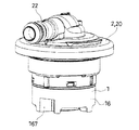
- FIG. 1 is a perspective view of a valve device according to an embodiment of the present invention.
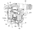
- FIG. 2 is a sectional view of the valve device.
- FIG. 3 is a cross-sectional view of the valve device, showing the valve device in cross section at a position 90 degrees different from FIG.
- FIG. 4 is a cross-sectional perspective view of the main part of the valve device.
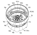
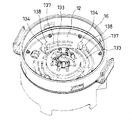
- FIG. 5 is a perspective view of the lower body constituting the case of the valve device.
- FIG. 6 is a perspective view of the lower body of FIG.
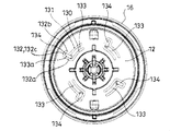
- FIG. 7 is a plan view of the lower body of FIG.
- FIG. 8 is a plan view showing a first modified example in which a part of the configuration of the lower body is modified.
- FIG. 9 is a perspective view showing a second modified example in which a part of the configuration of the lower body is changed.
- FIG. 10 is a plan view of the second modified example.
- FIG. 11 is a perspective view of a main part showing a third modified example in which a part of the configuration of the lower body is modified.
- FIG. 12 is a main part perspective view showing a fourth modified example in which a part of the configuration of the lower body is modified.
- FIG. 13 is a perspective view of a principal part showing a fifth modified example in which a part of the configuration of the lower body is modified.
- the fuel tank valve device is attached to a fuel tank T such as an automobile or a two-wheeled automobile, and functions so as to communicate between the inside and outside of the tank when the valve is open.
- Such a valve device is typically attached to the upper part of the fuel tank T and constitutes a part of a connection passage (air passage E) to the fuel tank T. Further, in the illustrated example, such a valve device uses the rise in the fuel liquid level due to the injection of the fuel F into the fuel tank T to cut off the communication inside and outside the tank, thereby increasing the pressure in the tank. It functions to raise the fuel level in the pipe and cause the fuel gun sensor to detect a full tank.
- the valve device firstly raises the lower float body 5 described later when the fuel level in the fuel tank T reaches a predetermined first level fa.
- the air passage E is squeezed, and the fuel level in a feeler pipe (not shown) is raised by an increase in the pressure in the fuel tank T, thereby causing the fuel gun sensor to detect the first full tank.
- the pressure in the fuel tank T is lowered by venting through the throttled air passage E to lower the fuel level in the feeler pipe. Allow additional lubrication.
- the valve device includes a case 1, an upper float body 3, and a lower float body 5.
- the case 1 includes a vent valve port 10 that communicates with the outside of the tank at the top, a fuel inflow portion 11 below the top, and a partition wall 12 formed between the vent valve port 10 and the inflow portion 11. It is divided into a chamber 13 and a lower chamber 14.
- the case 1 includes an upper body 15 and a lower body 16.
- the upper body 15 is configured to have a cylindrical shape.
- the upper end of the cylinder of the upper body 15 is closed by a top plate portion 15a having a circular vent valve port 10 at the center.
- a short cylindrical portion 15b is formed integrally with the top plate portion 15a so that the in-cylinder space communicates with the vent valve port 10 and protrudes upward from the top plate portion 15a.
- a seal ring 15c is fitted on the outside of the short cylindrical portion 15b.
- the lower end of the cylinder of the upper body 15 is open.
- the lower body 16 is configured to have a cylindrical shape in which both the upper and lower ends of the cylinder are opened. Between the upper and lower ends of the cylinder of the lower body 16, a partition wall 160 that divides the space in the lower body 16 in the vertical direction is formed. A circular through hole 161 a is formed at the center of the partition wall 160, and this through hole 161 a serves as a main communication portion 161 described later. In addition, through holes 162a serving as sub-communication portions 162 (described later) smaller than the through holes 161a are formed at both side positions sandwiching the through holes 161a.
- a disk-like body 163 having an outer diameter substantially equal to the hole diameter of the through hole 161a is directly above the through hole 121a of the partition wall 160, and the outer edge of the disk-like body 163 overlaps with the hole edge of the through hole 161a.
- a gap is provided between the lower surface of the disk-shaped body 163 and the upper surface of the partition wall 160 in the vertical direction.
- bridging pieces 164 extending between the disk-shaped body 163 and the partition wall 160 are provided at four positions at intervals in a direction around the center of the disk-shaped body 163, and the four bridging pieces 164.
- the disk-like body 163 is supported on the partition wall 160 as described above.
- the partition wall 12 is configured by the partition wall 160 and the disk-like body 163.
- the insertion part 165 includes an insertion hole 165a provided in a penetrating manner in the center of the disk-like body 163, and a cylindrical support part that protrudes upward from the upper surface of the disk-like body 163 so that the lower end of the cylinder communicates with the insertion hole 165a. 165b.
- a plurality of protrusions 166, 166,... are formed on the upper surface of the disk-shaped body 163 at substantially equal intervals between adjacent protrusions 166 on a virtual circular arc surrounding the cylindrical support portion 165b.
- the lower ends of the springs are combined with the disk-like body 163 so that the projections 166, 166,...
- a recess 167 formed so as to be recessed inwardly on the side of the lower body 16 is formed at a position on the lower end side of the cylinder of the lower body 16 and directly below the sub-communication portion 162.
- the recess 167 is formed on the left and right sides of the lower body, and the lower float body 5 described later moves up and down between the left and right recesses 167.
- the recess 167 is opened at the lower end of the cylinder of the lower body 16, and the upper portion thereof is closed by a portion where the sub-communication portion 162 is formed in the partition wall 12.
- the case 1 is configured by fitting the upper body 15 into the lower body 16 from the lower end side inside the portion above the partition wall 160 in the lower body 16.
- the case 1 configured as described above causes the lower end of the cylinder of the lower body 16 and the recess 167 to function as the inflow portion 11.
- the case 1 is combined with the flange 2 and is attached to the fuel tank T by the flange 2.
- the flange 2 has a head portion 20 and a cylindrical connecting portion 21 protruding downward from the head portion 20.
- the head 20 is integrally provided with a connecting pipe portion 22 protruding sideways, and the connecting pipe portion 22 communicates with the space in the cylindrical connecting portion 21 at the center of the head 20.
- This communication portion is surrounded by a circumferential rising portion 23 inside the flange 2.
- the upper portion of the upper body 15 is fitted inside the cylindrical connecting portion 21 of the flange 2 so that the short cylindrical portion 15b of the upper body 15 is inserted into the circumferential rising portion 23 of the flange 2.
- the flange 2 and the case 1 are integrated.
- a space between the short cylindrical portion 15b of the upper body 15 and the circumferential rising portion 23 of the flange 2 is sealed in an airtight state by the seal ring 15c.
- the inside and outside of the tank are communicated with each other through the inflow portion 11, the vent valve port 10, and the connecting pipe portion 22 of the case 1.
- the case 1 is inserted from the outside into a mounting hole Ta opened in a fuel tank T of a size that does not allow the head 20 of the flange 2 to enter, and the head 20 of the flange 2 is placed in the fuel tank.
- the fuel tank T is provided by being welded or the like to the outer surface portion of the T.
- the upper float body 3 is in the upper chamber 13 of the case 1 and is raised by the fuel flowing into the case 1 and seated on the vent valve port 10. When no fuel is flowing into the upper chamber 13, the upper float body 3 is in a lowered position supported by the partition wall 12 of the lower body 16, and the vent valve port 10 is open. That is, in this embodiment, the partition wall 12 functions as a surface portion facing the bottom of the upper float body 3 in the case 1.
- the upper float body 3 includes a float main body 30 including a top portion and a cylindrical side portion, and a sealing member 31 of the vent valve port 10 made of a material having elasticity.
- the support member 32 of the seal member 31 is provided.
- the support member 32 is configured to have a substantially disc shape with an engaging claw 32a protruding downward on the outer peripheral portion and a through hole 32b in the central portion.
- An engaged portion 30a to be engaged with an engaging claw 32a of the supporting member 32 is formed on the outer peripheral portion of the top portion of the float main body 30, and the supporting member 32 engages the engaging claw 32a with the engaged portion 30a. In this state, it is arranged on the top of the float main body 30.
- the seal member 31 has a disk shape with an outer diameter that closes the vent valve port 10 and has a fitting protrusion 31a for the through hole 32b of the support member 32 at the center of the lower portion, and the support member 32 has the fitting protrusion 31a. So that it is positioned directly below the vent valve port 10.
- the upper float body 3 is provided with an accommodation hole 33 in which a later-described guide shaft 50 of the lower float body 5 is accommodated.
- the accommodation hole 33 is formed in a recess 30 b formed in the center of the lower part of the float main body 30 of the upper float body 3.
- the recess 30b has a circular hole shape.
- a boss 30c protruding downward from the upper bottom of the recess 30b is formed in the recess 30b.
- the lower end of the boss 30c is positioned above the bottom of the cylinder of the upper float body 3, and the cylindrical support 165b and the protrusion 166 are moved into the recess 30b below the lower end of the boss 30c when the upper float 3 is lowered. 166... Fits in a row.
- the compression coil spring 4 is housed in the recess 30b in a compressed state so that the boss 30c is housed inside.
- the lower end of the spring 4 is in contact with the partition wall 160 of the lower body 16, and the upper end of the spring is in contact with the upper bottom of the recess 30 b, so that a certain upward force is applied to the upper float body 3 by the spring 4. It has become.
- the lower float body 5 has a guide shaft 50 protruding upward, and the guide shaft 50 is inserted into an insertion portion 165 formed in the partition wall 12 from the lower chamber 14 side of the case 1 so as to be movable up and down. 14 and supported by the fuel flowing into the case 1 to close the main communication portion 161 between the lower chamber 14 and the upper chamber 13 formed in the partition wall 12.
- the lower float body 5 has a float main body 51 that is accommodated under the partition wall 12 of the lower body 16 so as to be movable up and down, and the guide shaft 50.
- the float main body 51 has a short cylindrical shape, and is accommodated in the lower body 16 so that its cylinder axis is along the vertical direction.
- the upper end of the cylinder of the float main body 51 is closed and the lower end of the cylinder is opened.
- the outer diameter of the lower float body 5 is larger than that of the main communication portion 161 provided on the partition wall 160 constituting the partition wall 12.
- the guide shaft 50 has a head 50a at the upper end. Further, the outer diameter of the intermediate part between the head part 50a and the base part is made substantially equal to the inner diameter of the upper end of the cylindrical support part 165b constituting the insertion part 165, and the outer diameter of the base part is made substantially the same as that of the head part 50a. It is made equal and thicker than the middle part so as to be substantially equal to the hole diameter of the insertion hole 165a constituting the insertion part 165.
- the lower float body 5 hooks the head 50a of the guide shaft 50 passed through the cylindrical support portion 165b through the insertion hole 165a to the upper end of the cylinder of the cylindrical support portion 165b.
- the ventilation inside and outside the tank is secured through the inflow part 11, the main communication part 161, the sub-communication part 162, and the vent valve port 10.
- Ventilation through the main communication portion 161 is performed between the side surface of the float main body 51 of the lower float body 5 and the inner surface of the lower body 16, and ventilation through the sub communication portion 162 is performed through the recess 167 and through the vent valve port 10.
- the ventilation is performed between the side of the float main body 30 of the upper float body 3 and the inner surface of the upper chamber 13.
- the fuel F is lowered by the pressure difference between the pressure in the tank and the pressure in the case 1.
- the lower float body 5 is raised, whereby the main communication portion 161 is closed, and the fuel level in the feeler pipe is raised by the pressure increase in the tank, and the sensor of the fuel gun is first filled. Detect the tongue.
- the lower float body 5 stays only at closing the main communication part 161, so that the internal pressure in the tank is lowered by ventilation and additional refueling becomes possible.
- additional oil supply is permitted mainly by ventilation through the recess 167 and the sub-communication portion 162.
- the fuel enters the upper chamber 13 and the upper float body 3 rises and is seated on the vent valve port 10.
- the fuel level in the feeler pipe is raised again by the pressure increase in the tank, and the fuel tank sensor detects the final full tank.
- the fuel liquid level reaches the upper part of the recess 167 (second liquid level fb)
- the fuel passes through the sub-communication part 162 and the upper chamber 13 due to the pressure difference between the pressure in the tank and the pressure in the case 1. Get inside.
- the fuel F flows out from the upper chamber 13, the upper float body 3 is lowered, and the vent valve port 10 is opened.
- the lower float body 5 is moved.
- the main communication part 161 is opened by lowering.
- the guide shaft 50 of the lower float body 5 is the upper part. It fits in the accommodation hole 33 of the float body 3.
- an engaging portion that allows passage from below the head portion 50a of the guide shaft 50 is formed at the upper end of the insertion portion 165 by elastic deformation.
- the cylindrical support portion 165b is constituted by four elastic pieces 165c... 165c, and when the guide shaft 50 is passed through the insertion portion 165 from below through the insertion holes 165a, the four elastic pieces 165c. After starting to bend outward, the head 50a is bent back and engaged with the head 50a at a position where the head 50a has come out from the upper end of the elastic piece 165c.
- a structure is provided that absorbs impact energy at the bottom of the body 3 to prevent collision noise.
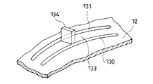
- the partition wall 12 as the surface portion has a first arc-shaped dividing groove 130 formed so that the center, in the illustrated example, the main communication portion 161 side is the curved inner side.
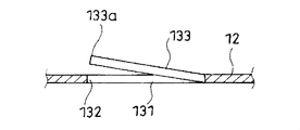
- the elastic piece 133 is formed by a part of the partition wall 12 by the second arcuate dividing groove 131 formed so that the center of the surface portion is curved inside on the outside of the first arcuate dividing groove 130. Is formed. A part of the elastic piece 133 comes into contact with the bottom when the upper float body 3 is lowered.
- the thickness of the elastic piece 133 in the vertical direction is equal to the thickness of the partition wall 12.
- the elastic body 133 can be provided with a desired elastic deformation characteristic by using the lower body 16 as a synthetic resin molded product.
- the elastic piece 133 Since the elastic piece 133 is formed by the first arc-shaped dividing groove 130 and the second arc-shaped dividing groove 131 formed as described above, the elastic piece 133 also has a curved inner side at the center side of the surface portion. Even when a space for forming the elastic piece 133 on the surface portion of the case 1 cannot be secured widely, specifically, between the main communication portion 161 and the side portion of the case 1, Even when a large space cannot be secured, the elastic piece 133 can be formed as long as possible. Accordingly, the amount of deflection of the elastic piece 133 when a part of the elastic piece 133 comes into contact with the upper float body 3 is increased as much as possible, and the impact energy of this contact is sufficiently given to the elastic piece 133. Can be absorbed.
- the elastic piece 133 makes it difficult for vibrations of the vehicle to travel to the upper float body 3 when the upper float body 3 is lowered, and the float main body constituting the upper float body 3 is thereby prevented. Occurrence of abnormal noise or wear between the support member 32 of the seal member 30 and the seal member 31 is also suppressed.
- the elastic piece 133 includes the first and second arc-shaped dividing grooves 130 and 131 and one end of the first and second arc-shaped dividing grooves 130 and 131.
- the elastic piece 133 is formed by a curved piece formed by a communicating portion 132 that communicates with each other.
- a free end 133a of the elastic piece 133 is provided with a contact portion 134 that protrudes from the bottom of the upper float body 3, and the contact portion 134 is provided.
- the bottom float of the upper float body 3 is contacted.
- the case 1 has a cylindrical shape, and the elastic piece 133 is formed along a virtual circular arc centering on the cylinder axis of the case 1.
- the communication portion 132 is formed so that the width of the free end 133a of the elastic piece 133 is larger than the remaining portion.
- the area of the portion of the elastic piece 133 that is in contact with the bottom of the upper float body 3 while the remaining portion of the elastic piece 133 is configured to be elastically deformable, that is, The area of the protruding end of the contact portion 134 can be increased as much as possible, and the upper float body 3 in the lowered position can be stably supported by the elastic piece 133.
- the communication portion 132 is formed by crossing the first arcuate dividing groove 130 perpendicularly to the first arcuate dividing groove 130 and extending outward from one end of the first arcuate dividing groove 130.
- a second split groove 132b extending outwardly from one end of the second arc-shaped split groove 131 perpendicular to the arc-shaped split groove 131, a terminal of the first split groove 132a, and a terminal of the second split groove 132b;
- a third split groove 132c for communicating with each other.
- the communicating portion 132 causes the elastic piece 133 to be bent toward the side of the case 1 with its free end 133a side in a plan view.
- the surface portion of the case 1 is separated from the adjacent elastic piece 133 in the direction of circling the center of the surface portion by two or more elastic members.
- the pieces 133, 133, ... are provided.
- the plurality of elastic pieces 133, 133... Are positioned at one base end of the elastic piece 133 adjacent to the front of the free end 133 a in the direction of circling the center of the surface portion, and behind the base end. It arrange
- the communication portion 132 includes a first split groove 132a extending inward from one end of the first arc-shaped split groove 130 perpendicular to the first arc-shaped split groove 130; A second split groove 132b extending inward from one end of the second arc-shaped split groove 131 perpendicular to the second arc-shaped split groove 131, and a terminal of the first split groove 132a and the second split groove 132b It is comprised by the 3rd dividing groove 132c which connects with the terminal of this.
- the communicating portion 132 causes the elastic piece 133 to be bent toward the center side of the case 1 with the free end 133a side in a plan view.
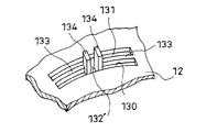
- an additional elastic piece 137 is further formed outside the elastic piece 133 shown in FIGS.
- a third arc-shaped split groove 135 formed so that the center of the surface portion of the case 1 is curved inside on the outside of the second arc-shaped split groove 131, and the second arc-shaped split groove
- An additional elastic piece 137 having a free end 133a on the side of the additional communication portion 136 is formed by one end of the groove 131 and the additional communication portion 136 that communicates between one end of the third arc-shaped dividing groove 135.
- the free end 137a of the additional elastic piece 137 is provided with a contact portion 138 protruding from the bottom of the float body.
- the elastic piece 133 and the additional elastic piece 137 that are in contact with the bottom of the upper float body 3 when the upper float body 3 is lowered are elastically deformed in the limited space.
- the additional communication portion 136 is configured by a fourth split groove 136a that allows one end of the third arc-shaped split groove 135 to communicate with the end of the third split groove 132c.
- the free end 137 a of the additional elastic piece 137 is positioned closer to the other end side of the first arc-shaped dividing groove 130 than the free end 133 a of the elastic piece 133.
- the protruding dimension of the contact part 138 of the additional elastic piece 137 is smaller than the protruding dimension of the contact part 134 of the elastic piece 133. Accordingly, in this example, when the upper float body 3 is lowered, the elastic piece 133 first comes into contact with the bottom of the upper float body 3 at the contact portion 134, and then the elastic piece 133 is bent by the contact. The contact portion 138 of the additional elastic piece 137 is brought into contact with the bottom of the upper float body 3 that is further moved downward by the insertion.
- the elastic piece 133 is provided with a contact portion 134 protruding upward at the center of the curved piece formed between the first and second arc-shaped dividing grooves 130 and 131.
- abut to the bottom part of the upper float body 3 in the contact part 134 is shown.
- FIG. 12 shows a communication in which the elastic piece 133 is communicated between the first and second arc-shaped split grooves 130 and 131 and one end of the first and second arc-shaped split grooves 130 and 131. And the free end 133a of the curved piece is positioned above the remaining portion of the surface portion so that the upper float body 3 of the upper float body 3 is formed at the free end 133a.
- abut to a bottom part is shown.
- FIG. 13 shows the first and second arc-shaped dividing grooves 130 by the communication portion 132 ′ that communicates the intermediate position of the first arc-shaped dividing groove 130 and the intermediate position of the second arc-shaped dividing groove 131.
- 131 are formed with two curved pieces, and the two curved pieces are used to form two elastic members having their free ends facing each other between the first and second arc-shaped split grooves 130, 131 via the communicating portion 132 ′.
- the example of a change which formed the pieces 133 and 133 is shown.
- Each elastic piece 133 is provided with a contact portion 134 protruding upward at its free end.
- the contact portion 134 contacts the bottom of the upper float body 3.
Landscapes
- Engineering & Computer Science (AREA)
- General Engineering & Computer Science (AREA)
- Mechanical Engineering (AREA)
- Cooling, Air Intake And Gas Exhaust, And Fuel Tank Arrangements In Propulsion Units (AREA)
- Self-Closing Valves And Venting Or Aerating Valves (AREA)
Description
タンク外と通じる通気弁口を上部に備え、これより下方に燃料の流入部を備えるケースと、
ケース内にあってケース内に流入される燃料によって上昇して前記通気弁口に着座されるフロート体とを備えていると共に、
前記ケースにおけるフロート体の底部に向き合う面部に、この面部の中央側を湾曲内側とするように形成される第一の円弧状割溝と、この第一の円弧状割溝の外側においてこの面部の中央を湾曲内側とするように形成される第二の円弧状割溝とにより、弾性片が形成されており、
この弾性片の一部が前記フロート体の底部に当接されるようになっているものとした。
なお、2012年3月22日に出願された日本特許出願第2012-065643号の明細書、特許請求の範囲、図面及び要約書の全内容をここに引用し、本発明の明細書の開示として、取り入れるものである。
Claims (6)
- 燃料タンクに取り付け用いられる弁装置であって、
タンク外と通じる通気弁口を上部に備え、これより下方に燃料の流入部を備えるケースと、
ケース内にあってケース内に流入される燃料によって上昇して前記通気弁口に着座されるフロート体とを備えていると共に、
前記ケースにおけるフロート体の底部に向き合う面部に、この面部の中央側を湾曲内側とするように形成される第一の円弧状割溝と、この第一の円弧状割溝の外側においてこの面部の中央を湾曲内側とするように形成される第二の円弧状割溝とにより、弾性片が形成されており、
この弾性片の一部が前記フロート体の底部に当接されるようになっていることを特徴とする燃料タンク用弁装置。 - ケースにおけるフロート体の底部に向き合う面部に、この面部の中央を湾曲内側とするように形成される第一の円弧状割溝と、この第一の円弧状割溝の外側においてこの面部の中央を湾曲内側とするように形成される第二の円弧状割溝と、両円弧状割溝の溝一端間を連通させる連通部とにより、この連通部側を自由端とする弾性片が形成されており、
この弾性片の自由端に前記フロート体の底部に対する当接部を突設させてなることを特徴とする請求項1に記載の燃料タンク用弁装置。 - 弾性片の自由端の幅をその余の箇所より大きくさせるように連通部が形成されていることを特徴とする請求項2に記載の燃料タンク用弁装置。
- ケースの面部の中央を周回する方向において、隣り合う弾性片との間に間隔を開けて、二以上の弾性片を設けさせてなることを特徴とする請求項1~請求項3のいずれか1項に記載のを燃料タンク用弁装置。
- 第二の円弧状割溝の外側においてケースの面部の中央を湾曲内側とするように形成される第三の円弧状割溝と、前記第二の円弧状割溝の溝一端と第三の円弧状割溝の溝一端間を連通させる追加連通部とにより、この連通部側を自由端とする追加弾性片が形成されており、
この追加弾性片の自由端に前記フロート体の底部に対する当接部を突設させてなることを特徴とする請求項2~請求項4のいずれか1項に記載の燃料タンク用弁装置。 - ケースは円筒状をなしていると共に、弾性片はこのケースの筒軸を中心とした仮想の円の円弧に沿うように形成されていることを特徴とする請求項1~請求項5のいずれか1項に記載の燃料タンク用弁装置。
Priority Applications (4)
| Application Number | Priority Date | Filing Date | Title |
|---|---|---|---|
| US14/374,718 US9518671B2 (en) | 2012-03-22 | 2013-03-18 | Valve device for fuel tank |
| JP2014506232A JP6113146B2 (ja) | 2012-03-22 | 2013-03-18 | 燃料タンク用弁装置 |
| EP13765268.1A EP2829428B1 (en) | 2012-03-22 | 2013-03-18 | Valve device for fuel tank |
| CN201380005606.8A CN104053565B (zh) | 2012-03-22 | 2013-03-18 | 燃料箱用阀装置 |
Applications Claiming Priority (2)
| Application Number | Priority Date | Filing Date | Title |
|---|---|---|---|
| JP2012065643 | 2012-03-22 | ||
| JP2012-065643 | 2012-03-22 |
Publications (1)
| Publication Number | Publication Date |
|---|---|
| WO2013141220A1 true WO2013141220A1 (ja) | 2013-09-26 |
Family
ID=49222677
Family Applications (1)
| Application Number | Title | Priority Date | Filing Date |
|---|---|---|---|
| PCT/JP2013/057730 Ceased WO2013141220A1 (ja) | 2012-03-22 | 2013-03-18 | 燃料タンク用弁装置 |
Country Status (5)
| Country | Link |
|---|---|
| US (1) | US9518671B2 (ja) |
| EP (1) | EP2829428B1 (ja) |
| JP (1) | JP6113146B2 (ja) |
| CN (1) | CN104053565B (ja) |
| WO (1) | WO2013141220A1 (ja) |
Cited By (3)
| Publication number | Priority date | Publication date | Assignee | Title |
|---|---|---|---|---|
| WO2022168676A1 (ja) * | 2021-02-02 | 2022-08-11 | 株式会社パイオラックス | 弁装置 |
| US11511620B2 (en) | 2018-01-19 | 2022-11-29 | Kyosan Denki Co., Ltd. | Ventilation control valve for fuel tank |
| US12172515B2 (en) | 2020-06-15 | 2024-12-24 | Piolax, Inc. | Valve device |
Families Citing this family (9)
| Publication number | Priority date | Publication date | Assignee | Title |
|---|---|---|---|---|
| JP6200097B2 (ja) * | 2014-08-25 | 2017-09-20 | 株式会社パイオラックス | 弁ケースの取付構造 |
| JP6620511B2 (ja) * | 2015-10-22 | 2019-12-18 | 京三電機株式会社 | 燃料タンク用通気制御弁 |
| JP6520639B2 (ja) * | 2015-10-22 | 2019-05-29 | 京三電機株式会社 | 燃料タンク用通気制御弁 |
| KR101784622B1 (ko) * | 2016-08-18 | 2017-10-11 | 주식회사 니프코코리아 | 연료탱크용 과충전 방지 도출밸브 |
| JP6841251B2 (ja) * | 2018-02-23 | 2021-03-10 | 豊田合成株式会社 | 燃料バルブ |
| DE202020103584U1 (de) * | 2020-01-29 | 2020-07-03 | Alfmeier Präzision SE | Ventil |
| US12123507B2 (en) * | 2020-11-26 | 2024-10-22 | Yingzhi Aiyi Intelligent Automotive Technologies (Jiaxing) Co., Ltd. | Valve, multi-functional combination valve and CFLVV valve |
| CN113550851B (zh) * | 2021-08-27 | 2022-12-13 | 山东速力动力科技有限公司 | 一种发动机燃油控制系统用起动排气装置 |
| CN120576273A (zh) * | 2025-08-01 | 2025-09-02 | 戴胜汽车科技(苏州)有限公司 | 一种自动增加浮力的油箱控制阀浮子及其控制阀 |
Citations (5)
| Publication number | Priority date | Publication date | Assignee | Title |
|---|---|---|---|---|
| JPH0675852U (ja) * | 1992-12-12 | 1994-10-25 | 現代自動車株式会社 | 自動車用燃料逆流防止装置 |
| JP3323289B2 (ja) | 1993-07-20 | 2002-09-09 | 株式会社ニフコ | 燃料カットバルブ |
| JP2003505654A (ja) | 1999-07-23 | 2003-02-12 | ラバル−アグリカルチュラル・コーオペレイティブ・ソサイエティーズ・リミテッド | 静音化されたバルブ |
| JP2007331448A (ja) * | 2006-06-13 | 2007-12-27 | Toyoda Gosei Co Ltd | 燃料遮断弁 |
| JP2008247159A (ja) * | 2007-03-30 | 2008-10-16 | Toyoda Gosei Co Ltd | 燃料タンクの給油量規制装置 |
Family Cites Families (9)
| Publication number | Priority date | Publication date | Assignee | Title |
|---|---|---|---|---|
| US2957546A (en) * | 1957-04-23 | 1960-10-25 | Robert G Saunders | Railway journal box vent |
| US4346731A (en) * | 1981-05-26 | 1982-08-31 | Chevron Research Company | Buoyant element check valve for a thermosiphon energy system |
| JP2002147632A (ja) * | 2000-08-29 | 2002-05-22 | Nifco Inc | 弁装置 |
| US6561211B2 (en) * | 2000-10-19 | 2003-05-13 | Stant Manufacturing Inc. | Fuel tank vent control valve |
| JP4394508B2 (ja) | 2004-04-14 | 2010-01-06 | 株式会社ニフコ | 燃料タンク用バルブ |
| JP4329769B2 (ja) * | 2006-02-15 | 2009-09-09 | 豊田合成株式会社 | 燃料遮断弁 |
| JP5285888B2 (ja) * | 2007-10-02 | 2013-09-11 | 株式会社ニフコ | 弁装置 |
| US8371326B2 (en) | 2009-05-11 | 2013-02-12 | Eaton Corporation | Fuel vapor vent valve with dynamic pressure relief |
| KR101300925B1 (ko) * | 2011-11-28 | 2013-08-27 | 주식회사 동희산업 | 소음 방지타입 연료탱크 벤트 밸브 |
-
2013
- 2013-03-18 JP JP2014506232A patent/JP6113146B2/ja active Active
- 2013-03-18 US US14/374,718 patent/US9518671B2/en active Active
- 2013-03-18 EP EP13765268.1A patent/EP2829428B1/en active Active
- 2013-03-18 WO PCT/JP2013/057730 patent/WO2013141220A1/ja not_active Ceased
- 2013-03-18 CN CN201380005606.8A patent/CN104053565B/zh active Active
Patent Citations (5)
| Publication number | Priority date | Publication date | Assignee | Title |
|---|---|---|---|---|
| JPH0675852U (ja) * | 1992-12-12 | 1994-10-25 | 現代自動車株式会社 | 自動車用燃料逆流防止装置 |
| JP3323289B2 (ja) | 1993-07-20 | 2002-09-09 | 株式会社ニフコ | 燃料カットバルブ |
| JP2003505654A (ja) | 1999-07-23 | 2003-02-12 | ラバル−アグリカルチュラル・コーオペレイティブ・ソサイエティーズ・リミテッド | 静音化されたバルブ |
| JP2007331448A (ja) * | 2006-06-13 | 2007-12-27 | Toyoda Gosei Co Ltd | 燃料遮断弁 |
| JP2008247159A (ja) * | 2007-03-30 | 2008-10-16 | Toyoda Gosei Co Ltd | 燃料タンクの給油量規制装置 |
Non-Patent Citations (1)
| Title |
|---|
| See also references of EP2829428A4 |
Cited By (5)
| Publication number | Priority date | Publication date | Assignee | Title |
|---|---|---|---|---|
| US11511620B2 (en) | 2018-01-19 | 2022-11-29 | Kyosan Denki Co., Ltd. | Ventilation control valve for fuel tank |
| US12172515B2 (en) | 2020-06-15 | 2024-12-24 | Piolax, Inc. | Valve device |
| WO2022168676A1 (ja) * | 2021-02-02 | 2022-08-11 | 株式会社パイオラックス | 弁装置 |
| JP7442698B2 (ja) | 2021-02-02 | 2024-03-04 | 株式会社パイオラックス | 弁装置 |
| US12179575B1 (en) | 2021-02-02 | 2024-12-31 | Piolax, Inc. | Valve device |
Also Published As
| Publication number | Publication date |
|---|---|
| EP2829428A4 (en) | 2015-11-18 |
| CN104053565B (zh) | 2017-10-03 |
| EP2829428B1 (en) | 2018-01-03 |
| CN104053565A (zh) | 2014-09-17 |
| JPWO2013141220A1 (ja) | 2015-08-03 |
| US9518671B2 (en) | 2016-12-13 |
| US20150034174A1 (en) | 2015-02-05 |
| JP6113146B2 (ja) | 2017-04-12 |
| EP2829428A1 (en) | 2015-01-28 |
Similar Documents
| Publication | Publication Date | Title |
|---|---|---|
| JP6113146B2 (ja) | 燃料タンク用弁装置 | |
| US9783046B2 (en) | Valve device for fuel tank | |
| JP5517600B2 (ja) | 燃料タンク用弁装置 | |
| JP5265262B2 (ja) | フロート弁装置 | |
| US9879777B2 (en) | Shock absorber and piston | |
| US8220481B2 (en) | Fuel shutoff valve | |
| US10113514B2 (en) | Valve device | |
| JPWO2013069532A1 (ja) | 弁装置 | |
| EP3599122B1 (en) | Valve device for fuel tank | |
| US10041601B2 (en) | Valve device | |
| US20240255065A1 (en) | Valve device for fuel tank | |
| US20050055817A1 (en) | Fuel vapor vent valve and method of attaching same to a tank | |
| EP3118463B1 (en) | Accumulator | |
| JP6427071B2 (ja) | 燃料供給装置 | |
| KR101300925B1 (ko) | 소음 방지타입 연료탱크 벤트 밸브 | |
| US20190136798A1 (en) | Check valve | |
| JP2024011681A (ja) | 燃料供給装置 | |
| KR20140048770A (ko) | 밀폐형 연료탱크의 배플 장치 | |
| JP5307739B2 (ja) | 緩衝器のバルブ構造 | |
| JP4335877B2 (ja) | フロート弁装置 | |
| US12287020B2 (en) | Anti-vibration device | |
| KR100957512B1 (ko) | 재충전이 불가능한 밸브 | |
| JP6196520B2 (ja) | 燃料流出防止弁 | |
| JP2013010532A (ja) | スプレー容器 | |
| JPWO2013175974A1 (ja) | フロート弁装置 |
Legal Events
| Date | Code | Title | Description |
|---|---|---|---|
| 121 | Ep: the epo has been informed by wipo that ep was designated in this application |
Ref document number: 13765268 Country of ref document: EP Kind code of ref document: A1 |
|
| ENP | Entry into the national phase |
Ref document number: 2014506232 Country of ref document: JP Kind code of ref document: A |
|
| WWE | Wipo information: entry into national phase |
Ref document number: 14374718 Country of ref document: US |
|
| WWE | Wipo information: entry into national phase |
Ref document number: 2013765268 Country of ref document: EP |
|
| NENP | Non-entry into the national phase |
Ref country code: DE |