WO2013141526A1 - Procédé permettant à un terminal d'accéder à un réseau dans un système de communication sans fil, et dispositif associé - Google Patents
Procédé permettant à un terminal d'accéder à un réseau dans un système de communication sans fil, et dispositif associé Download PDFInfo
- Publication number
- WO2013141526A1 WO2013141526A1 PCT/KR2013/002104 KR2013002104W WO2013141526A1 WO 2013141526 A1 WO2013141526 A1 WO 2013141526A1 KR 2013002104 W KR2013002104 W KR 2013002104W WO 2013141526 A1 WO2013141526 A1 WO 2013141526A1
- Authority
- WO
- WIPO (PCT)
- Prior art keywords
- priority
- terminal
- cell
- apply
- network
- Prior art date
- Legal status (The legal status is an assumption and is not a legal conclusion. Google has not performed a legal analysis and makes no representation as to the accuracy of the status listed.)
- Ceased
Links
Images


Classifications
-
- H—ELECTRICITY
- H04—ELECTRIC COMMUNICATION TECHNIQUE
- H04W—WIRELESS COMMUNICATION NETWORKS
- H04W36/00—Hand-off or reselection arrangements
- H04W36/24—Reselection being triggered by specific parameters
- H04W36/26—Reselection being triggered by specific parameters by agreed or negotiated communication parameters
-
- H—ELECTRICITY
- H04—ELECTRIC COMMUNICATION TECHNIQUE
- H04L—TRANSMISSION OF DIGITAL INFORMATION, e.g. TELEGRAPHIC COMMUNICATION
- H04L12/00—Data switching networks
- H04L12/02—Details
- H04L12/16—Arrangements for providing special services to substations
- H04L12/18—Arrangements for providing special services to substations for broadcast or conference, e.g. multicast
- H04L12/189—Arrangements for providing special services to substations for broadcast or conference, e.g. multicast in combination with wireless systems
-
- H—ELECTRICITY
- H04—ELECTRIC COMMUNICATION TECHNIQUE
- H04W—WIRELESS COMMUNICATION NETWORKS
- H04W48/00—Access restriction; Network selection; Access point selection
- H04W48/20—Selecting an access point
-
- H—ELECTRICITY
- H04—ELECTRIC COMMUNICATION TECHNIQUE
- H04W—WIRELESS COMMUNICATION NETWORKS
- H04W48/00—Access restriction; Network selection; Access point selection
- H04W48/16—Discovering, processing access restriction or access information
Definitions
- the present invention relates to a wireless communication system, and more particularly, to a method and apparatus for connecting a terminal to a network in a wireless communication system.
- a 3GPP LTE (3rd Generation Partnership Project Long Term Evolution (LTE)) communication system will be described.
- E-UMTS Evolved Universal Mobile Telecommunications System
- UMTS Universal Mobile Telecommunications System
- LTE Long Term Evolution
- an E-UMTS is located at an end of a user equipment (UE), an eNode B (eNB), and a network (E-UTRAN) and connected to an external network (Access Gateway; AG). It includes.
- the base station may transmit multiple data streams simultaneously for broadcast service, multicast service and / or unicast service.
- the cell is set to one of bandwidths such as 1.25, 2.5, 5, 10, 15, and 20Mhz to provide downlink or uplink transmission services to multiple terminals. Different cells may be configured to provide different bandwidths.
- the base station controls data transmission and reception for a plurality of terminals.
- the base station transmits downlink scheduling information for downlink (DL) data and informs the user equipment of time / frequency domain, encoding, data size, and HARQ (Hybrid Automatic Repeat and reQuest) related information.
- HARQ Hybrid Automatic Repeat and reQuest
- the base station transmits uplink scheduling information to uplink UL data for uplink (UL) data and informs the user equipment of time / frequency domain, encoding, data size, HARQ related information, and the like.
- the core network may be composed of an AG and a network node for user registration of the terminal.
- the AG manages the mobility of the UE in units of a tracking area (TA) composed of a plurality of cells.
- Wireless communication technology has been developed to LTE based on WCDMA, but the demands and expectations of users and operators are continuously increasing.
- new technological evolution is required to be competitive in the future. Reduced cost per bit, increased service availability, the use of flexible frequency bands, simple structure and open interface, and adequate power consumption of the terminal are required.
- the following is a method for connecting a terminal to a network in a wireless communication system and an apparatus therefor.
- a method of applying one or more priorities for cell reselection by a terminal includes: setting a first priority and a second priority; Applying the first priority for the cell reselection; And when the connection establishment with the network is requested, applying the second priority for the cell reselection.
- the one or more priorities are associated with a predetermined frequency for providing a service, and the service is a multimedia broadcast multicast service (MBMS) service.
- MBMS multimedia broadcast multicast service
- applying the first priority may include setting a priority of the predetermined frequency as the highest priority.
- applying the second priority may include setting a priority of the predetermined frequency to a priority signaled by the network.
- the method may further include determining whether to apply the second priority based on the cause of the connection establishment.
- the reason for establishing the connection is characterized in that the mo-data (mobile originating data).
- the reason for establishing the connection is emergency, high priority access, mobile terminating-access, mo-signaling (mobile originating-signaling), or mo-Data (mobile). It may be defined as one of originating data or delayTolerantAccess.
- the control information indicates the disallow of the first priority
- the second priority may be applied for the cell reselection.
- the control information indicates to allow the application of the first priority
- the first priority may be maintained for the cell reselection.
- the method comprises the steps of: receiving information about a specific connection reason from the network; And determining whether to apply the second priority based on the information about the specific connection reason.
- the connection reason of the connection establishment is the specific connection reason
- the second priority may be applied for the cell reselection.
- FIG. 1 is a diagram schematically illustrating an E-UMTS network structure as an example of a wireless communication system.
- E-UTRAN Evolved Universal Terrestrial Radio Access Network
- FIG. 3 is a diagram illustrating a control plane and a user plane structure of a radio interface protocol between a terminal and an E-UTRAN based on the 3GPP radio access network standard.
- FIG. 4 is a diagram for explaining physical channels used in a 3GPP system and a general signal transmission method using the same.
- FIG. 5 is a diagram illustrating a structure of a radio frame used in an LTE system.
- FIG. 6 is a diagram illustrating a general transmission and reception method using a call message.
- FIG. 7 is a flowchart illustrating the operation of the terminal when the terminal is powered on in the LTE system.
- FIG. 8 is a flowchart illustrating an RRC connection method of the present invention.
- FIG. 9 is a signal flow diagram illustrating an RRC connection method of the present invention.
- FIG. 10 is another signal flow diagram illustrating an RRC connection method of the present invention.
- FIG. 11 illustrates a block diagram of a communication device according to an embodiment of the present invention.
- E-UTRAN Evolved Universal Terrestrial Radio Access Network
- the E-UTRAN consists of cells (eNBs), which cells are connected via an X2 interface.
- the cell is connected to the terminal through the air interface, and is connected to the Evolved Packet Core (EPC) through the S1 interface.
- EPC Evolved Packet Core
- the EPC includes a mobility management entity (MME), a serving-gateway (S-GW), and a packet data network-gateway (PDN-GW).
- MME mobility management entity
- S-GW serving-gateway
- PDN-GW packet data network-gateway
- FIG. 3 is a diagram illustrating a control plane and a user plane structure of a radio interface protocol between a terminal and an E-UTRAN based on the 3GPP radio access network standard.
- the control plane refers to a path through which control messages used by a user equipment (UE) and a network to manage a call are transmitted.
- the user plane refers to a path through which data generated at an application layer, for example, voice data or Internet packet data, is transmitted.
- the physical layer which is the first layer, provides an information transfer service to an upper layer by using a physical channel.
- the physical layer is connected to the upper layer of the medium access control layer through a transport channel. Data moves between the medium access control layer and the physical layer through the transport channel. Data moves between the physical layer between the transmitting side and the receiving side through the physical channel.
- the physical channel utilizes time and frequency as radio resources. Specifically, the physical channel is modulated in the Orthogonal Frequency Division Multiple Access (OFDMA) scheme in the downlink, and modulated in the Single Carrier Frequency Division Multiple Access (SC-FDMA) scheme in the uplink.
- OFDMA Orthogonal Frequency Division Multiple Access
- SC-FDMA Single Carrier Frequency Division Multiple Access
- the medium access control (MAC) layer of the second layer provides a service to a radio link control (RLC) layer, which is a higher layer, through a logical channel.
- RLC radio link control
- the RLC layer of the second layer supports reliable data transmission.
- the function of the RLC layer may be implemented as a functional block inside the MAC.
- the PDCP (Packet Data Convergence Protocol) layer of the second layer performs a header compression function to reduce unnecessary control information for efficiently transmitting IP packets such as IPv4 or IPv6 in a narrow bandwidth wireless interface.
- IPv4 Packet Data Convergence Protocol
- the Radio Resource Control (RRC) layer located at the bottom of the third layer is defined only in the control plane.
- the RRC layer is responsible for control of logical channels, transport channels, and physical channels in connection with configuration, reconfiguration, and release of radio bearers (RBs).
- RB means a service provided by the second layer for data transmission between the terminal and the network.
- the RRC layers of the UE and the network exchange RRC messages with each other.
- One cell constituting the base station is set to one of the bandwidth, such as 1.25, 2.5, 5, 10, 15, 20Mhz to provide a downlink or uplink transmission service to multiple terminals.
- Different cells may be configured to provide different bandwidths.
- the uplink transmission channel for transmitting data from the terminal to the network includes a random access channel (RAC) for transmitting an initial control message and an uplink shared channel (SCH) for transmitting user traffic or a control message. It is located above the transport channel, and the logical channel mapped to the transport channel is a broadcast control channel (BCCH), a paging control channel (PCCH), a common control channel (CCCH), a multicast control channel (MCCH), and an MTCH (multicast). Traffic Channel).
- BCCH broadcast control channel
- PCCH paging control channel
- CCCH common control channel
- MCCH multicast control channel
- Traffic Channel multicast
- FIG. 4 is a diagram for explaining physical channels used in a 3GPP system and a general signal transmission method using the same.
- the UE When the UE is powered on or enters a new cell, the UE performs an initial cell search operation such as synchronizing with the base station (S401). To this end, the terminal may receive a Primary Synchronization Channel (P-SCH) and a Secondary Synchronization Channel (S-SCH) from the base station to synchronize with the base station and obtain information such as a cell ID. have. Thereafter, the terminal may receive a physical broadcast channel from the base station to obtain broadcast information in a cell. Meanwhile, the terminal may receive a downlink reference signal (DL RS) in an initial cell search step to check the downlink channel state.
- P-SCH Primary Synchronization Channel
- S-SCH Secondary Synchronization Channel
- DL RS downlink reference signal
- the UE After completing the initial cell search, the UE acquires more specific system information by receiving a physical downlink control channel (PDSCH) according to a physical downlink control channel (PDCCH) and information on the PDCCH. It may be (S402).
- PDSCH physical downlink control channel
- PDCCH physical downlink control channel
- the terminal may perform a random access procedure (RACH) for the base station (steps S403 to S406).
- RACH random access procedure
- the UE may transmit a specific sequence to the preamble through a physical random access channel (PRACH) (S403) and receive a response message for the preamble through the PDCCH and the corresponding PDSCH (S404).
- PRACH physical random access channel
- a contention resolution procedure may be additionally performed.
- the UE After performing the procedure as described above, the UE performs a PDCCH / PDSCH reception (S407) and a physical uplink shared channel (PUSCH) / physical uplink control channel (Physical Uplink) as a general uplink / downlink signal transmission procedure.
- Control Channel (PUCCH) transmission (S408) may be performed.
- the terminal receives downlink control information (DCI) through the PDCCH.
- DCI downlink control information
- the DCI includes control information such as resource allocation information for the terminal, and the format is different according to the purpose of use.
- the control information transmitted by the terminal to the base station through the uplink or received by the terminal from the base station includes a downlink / uplink ACK / NACK signal, a channel quality indicator (CQI), a precoding matrix index (PMI), and a rank indicator (RI). ), And the like.
- the terminal may transmit the above-described control information such as CQI / PMI / RI through the PUSCH and / or PUCCH.
- FIG. 5 is a diagram illustrating a structure of a radio frame used in an LTE system.
- a radio frame has a length of 10 ms (327200 ⁇ T s ) and consists of ten equally sized subframes.
- Each subframe has a length of 1 ms and consists of two slots.
- Each slot has a length of 0.5 ms (15360 x T s ).
- the slot includes a plurality of OFDM symbols in the time domain and a plurality of resource blocks (RBs) in the frequency domain.
- one resource block includes 12 subcarriers x 7 (6) OFDM symbols.
- Transmission time interval which is a unit time for transmitting data, may be determined in units of one or more subframes.
- the structure of the radio frame described above is merely an example, and the number of subframes included in the radio frame, the number of slots included in the subframe, and the number of OFDM symbols included in the slot may be variously changed.
- the RRC state refers to whether or not the RRC of the UE is in a logical connection with the RRC of the E-UTRAN. If connected, the RRC connected state (RRC_CONNECTED), if not connected, the RRC idle state (RRC_IDLE). It is called.
- the E-UTRAN can grasp the presence of the UE in the RRC connection state on a cell basis, the E-UTRAN can effectively control the UE.
- the E-UTRAN cannot grasp the UE of the RRC idle state in the cell unit, and the CN manages the TA unit, which is a larger area unit than the cell. That is, in order to receive a service such as voice or data from the cell, the UE in the RRC idle state needs to transition to the RRC connected state.
- the terminal when the user first turns on the power of the terminal, the terminal first searches for an appropriate cell and then stays in an RRC idle state in the cell. Only when it is necessary to establish an RRC connection, the UE remaining in the RRC idle state transitions to the RRC connection state by performing an RRC connection establishment process with the RRC of the E-UTRAN. In this case, when the RRC connection needs to be established, an uplink data transmission is necessary due to a user's call attempt, or when a paging message is received from the E-UTRAN, a response message should be transmitted.
- FIG. 6 is a diagram illustrating a general transmission and reception method using a call message.
- the call message includes a paging record composed of a paging cause, a terminal identifier, and the like.
- the terminal may perform a discontinuous reception period (DRX) for the purpose of reducing power consumption.
- DRX discontinuous reception period
- the network configures a plurality of paging occasions (POs) for each time period called a paging DRX cycle, and a specific terminal can receive only a specific paging opportunity time to obtain a paging message.
- the terminal may not receive a call channel during a time other than the specific call opportunity time and may be in a sleep state to reduce power consumption.
- One call opportunity time corresponds to one TTI.
- the base station and the terminal use a paging indicator (PI) as a specific value indicating the transmission of the call message.
- the base station may define a specific identifier (for example, Paging-Radio Network Temporary Identity (P-RNTI)) for the purpose of the PI to inform the terminal of the call information transmission. For example, the terminal wakes up every DRX cycle and receives one subframe to know whether a call message appears. If the P-RNTI is present in the L1 / L2 control channel (PDCCH) of the received subframe, the UE may know that there is a call message in the PDSCH of the corresponding subframe. In addition, if the call message has its own terminal identifier (eg, IMSI), the terminal receives the service by responding to the base station (eg, receiving RRC connection or system information).
- P-RNTI Paging-Radio Network Temporary Identity
- the service provided by the network to the terminal may be classified into three types. Depending on what service can be provided, the UE also recognizes the cell type differently. Meanwhile, in the 3GPP standard document, services provided by the network to the terminal are classified into three types as shown in Table 1 below.
- Table 1 Limited service Provide emergency call and Earthquake and Tsunami Warning System (ETWS) Normal service Providing general use public use services Operator service Providing services for network operators
- EWS Earthquake and Tsunami Warning System
- the 3GPP standard document classifies a cell type as shown in Table 2 below with respect to a service type that a cell provides to a terminal.
- the Acceptable cell is a cell that is not barred from the terminal's point of view and satisfies the cell selection criterion of the terminal, and is a cell that can receive only limited services such as emergency call and ETWS.
- Suitable cells also satisfy the conditions of the Acceptable cell, while at the same time satisfying additional conditions.
- this cell must belong to a PLMN to which the UE can access, and must be a cell in which the TA update procedure of the UE is not prohibited.
- the cell is a CSG (Closed Subscriber Group) cell, the terminal should be a cell that can be accessed as a CSG member.
- the terminal performs a cell selection procedure and registers itself with the network in order to receive a service from the cell. In addition, if the strength or quality of the signal between the terminal and the cell decreases due to the mobility of the terminal, the terminal performs a cell reselection procedure to maintain the transmission quality of the data.
- the 3GPP standard document divides the cell selection procedure into two categories as follows.
- the first is an initial cell selection process, which is performed when the terminal does not have prior information on the radio channel.
- the terminal searches all radio channels to find an appropriate cell, and selects a cell corresponding to the radio channel having the strongest signal quality among the searched radio channels.
- Equation 1 represents a cell selection criterion in the LTE system disclosed in the 3GPP standard document.
- Equation 1 Parameters used in Equation 1 are shown in Table 3 below.
- the terminal receives the parameters of Table 3 through system information (SI) and performs a cell selection procedure using the cell selection criteria of Equation 1.
- SI system information
- the above system information includes essential information that the terminal needs to know in order to access the cell. Therefore, the terminal must have the latest system information before accessing the cell. And since the system information is information that every terminal in a cell should know, the cell periodically transmits the system information.
- SIB system information block
- the MIB allows the terminal to know information such as physical configuration of the cell, for example, bandwidth.
- SIB is a collection of related system information. For example, some SIBs contain only information of neighboring cells, and some SIBs contain only information of uplink radio channels used by the terminal. SB informs transmission information of SIBs, for example, a transmission period.
- the terminal selects a cell through a cell selection procedure
- the strength or quality of the signal between the terminal and the cell may change due to the mobility of the terminal or a change in the wireless environment. If the quality of the selected cell is degraded, the terminal may select another cell that provides better quality. When reselecting a cell in this way, a cell that generally provides better signal quality than the currently selected cell is selected. This is called a cell reselection procedure.
- the cell reselection procedure has a basic purpose in selecting a cell that generally provides the best quality to a terminal in view of the quality of a radio signal.
- the network may determine the priority for each frequency and notify the terminal. Upon receiving this priority, the UE considers this priority in preference to the radio signal quality criteria in the cell reselection procedure.
- Such a cell reselection procedure may be divided according to the radio access technology (RAT) and frequency characteristics of the cell as shown in Table 4 below.
- RAT radio access technology
- FIG. 7 is a flowchart illustrating an operation of a terminal when the terminal is powered on in a Long Term Evolution (LTE) system.
- LTE Long Term Evolution
- the terminal selects a radio access technology (RAT) for communicating with a public land mobile network (PLMN), which is a network to be serviced automatically or manually when power is turned on.
- the PLMN and RAT information may be selected by a user of the terminal or may use information stored in a universal subscriber identity module (USIM).
- USIM universal subscriber identity module
- the UE measures the signal transmitted from the cell periodically or non-periodically, that is, a reference signal or a pilot signal as shown in step 130, and is related to the signal strength or the ratio of the signal and noise / interference.
- Cell quality information is calculated using the characteristics of the physical signal.
- the terminal performs a cell selection process of selecting a cell having the largest value among cells in which the measured cell quality information is larger than a reference value.
- the reference value refers to a value defined in the system to ensure the quality of the physical signal in data transmission and reception. Therefore, the value may vary according to the applied RAT, and may be based on Equation 1 in the LTE system.
- the terminal receives the system information periodically transmitted by the cell, and uses it to network its information (eg, International Mobile Subscriber Identity, IMSI) in order to receive the service from the network in step 150.
- network its information eg, International Mobile Subscriber Identity, IMSI
- the UE does not register with the network. If the network information received from the SI (e.g., Tracking Area Identity, TAI) is different from the network information known to the SI as in steps 140 and 170, the network is not registered.
- the SI e.g., Tracking Area Identity, TAI
- the terminal provides one of the other cells that provide better signal characteristics than the cell of the cell to which the terminal is connected. Reselect.
- This process is referred to as cell reselection in addition to cell selection in step 120.
- a temporal constraint eg, a cell selection timer
- MBMS Multimedia Broadcast Multicast Service
- MBMS Multimedia Broadcast Multicast Service
- the terms 'broadcast / multicast service' and 'MBMS' used in this document may be replaced with other terms such as 'point-to-multi-service' and 'multicast and broadcast service'.
- MBMS is based on IP multicast, and terminals receive the same multimedia data by sharing resources necessary for data packet transmission. Therefore, when a terminal of a certain level using the MBMS exists in the same cell, it is possible to increase the resource efficiency. Since the MBMS is independent of the RRC connection state, the terminal in the idle state can also be provided with the service.
- the logical channel MCMS (MBMS Control CHannel) or MBMS Traffic Channel (MTCH) for MBMS may be mapped to the transport channel MCH (MBMS CHannel).
- the MCCH transmits an RRC message including MBMS related common control information, and the MTCH transmits traffic of a specific MBMS.
- MBSFN Single Frequency Network
- the PDCCH transmits an MBMS Radio Network Temporary Identity (M-RNTI) and an indicator indicating a specific MCCH.
- M-RNTI MBMS Radio Network Temporary Identity
- the UE supporting the MBMS may receive the M-RNTI and the MCCH indicator through the PDCCH, determine that the MBMS related RRC message has been changed in the specific MCCH, and receive the specific MCCH.
- the RRC message of the MCCH may change at every change cycle, and is repeatedly broadcasted at every repetition cycle.
- some base stations can use multiple frequencies at the same time.
- the network may select one of a plurality of frequencies to provide an MBMS service only at that frequency and provide a dedicated bearer to each terminal at all frequencies.
- the terminal when a terminal that has received a service using a dedicated bearer at a frequency where the MBMS service is not provided, wants to receive the MBMS service, the terminal should be handed over to the frequency where the MBMS is provided. To this end, the terminal transmits the MBMS interest Indication to the base station.
- the terminal when the terminal wants to receive the MBMS service, the terminal transmits an MBMS interest indication to the base station, and upon receiving the MBMS interest indication, the base station recognizes that the terminal wants to receive the MBMS service and moves the terminal to a frequency where the MBMS is provided.
- the MBMS interest indication means information that the terminal wants to receive the MBMS service, and additionally includes information on which frequency it wants to move to.
- a terminal that wants to receive a specific MBMS service first grasps frequency information and broadcast time information provided with the specific service. If the MBMS service is already broadcasting or soon starts broadcasting, the terminal sets the highest priority of the frequency in which the MBMS service is provided. The UE moves to a cell providing the MBMS service and receives the MBMS service by performing a cell reselection procedure using the reset frequency priority information.
- the UE in the RRC idle state performs inter-frequency cell reselection based on a frequency priority set by the network.
- the terminal wants to receive the MBMS service, the terminal itself considers a specific frequency as a frequency priority other than the frequency priority set by the network, and performs cell reselection.
- an operation of performing cell reselection based on the frequency priority reset by the terminal may be referred to as autonomous priority handling.
- the network may inform the terminal of information that controls whether the terminal applies the autonomous priority, that is, autonomous priority controlling information in a broadcast format.
- the autonomous priority control information may be received. If the autonomous priority is indicated as non-permissible in this information, the user equipment may not be able to receive autonomous priority. Return to frequency priority.
- the present invention proposes a method for determining whether to apply autonomous priority based on autonomous priority control information received from a network, which can solve the above problem.
- the autonomous priority control information may include an indicator to allow or prohibit the application of autonomous priority of the terminal. If the indicator included in the autonomous priority control information indicates the acceptance of autonomous priority application, the UE attempts RRC access to a cell currently camped on while maintaining the autonomous priority. When the indicator included in the autonomous priority control information indicates the prohibition of the application of autonomous priority, the UE performs cell reselection by applying a default priority when requesting RRC access and requests the RRC access to the reselected cell. .
- the application target of the above-described method may be limited to a terminal that performs cell reselection by applying autonomous priority.
- the network may define an autonomous priority prohibit timer and signal it to set a time for prohibiting the application of autonomous priority. Subsequently, the terminal applying the default priority according to the control information prohibiting the application of the autonomous priority operates the autonomous priority prohibit timer. Therefore, the terminal does not apply the autonomous priority of setting the MBMS frequency as the highest priority while the timer is running. However, when the autonomous priority prohibit timer expires, the terminal may apply autonomous priority to set the MBMS frequency as the highest priority. Of course, the autonomous priority prohibit timer may be preset in the terminal.
- FIG. 8 is a flowchart illustrating an RRC connection method of the present invention.
- step 801 the UE performs cell reselection by applying the autonomous priority. Thereafter, autonomous priority control information may be received in step 802.
- the terminal may receive information indicating the congestion state of the camped-on cell from the network, and the autonomous priority control information may be obtained from information indicating the congestion state of the network, that is, congestion information.
- step 803 the terminal receives an RRC connection request from a non-access stratum (NAS) layer. If the autonomous priority control information indicates prohibition of application of autonomous priority, the UE performs cell reselection by applying the default priority as shown in step 804 and requests the RRC connection to the reselected cell as shown in step 805. .
- NAS non-access stratum
- the UE attempts RRC access to the cell currently camped on as shown in step 805 while maintaining the autonomous priority.
- the network may prohibit the frequency prioritization of the terminal trying to access the RRC for a certain reason. If the congestion is severe, the network can prevent the frequency priority of the terminal trying to access all RRC regardless of the connection reason, and if the congestion is enough to accommodate signaling such as TAU, the RRC connection is attempted for mo-Data. By prohibiting the frequency prioritization of the MBMS UE, it is possible to efficiently reduce the RRC connection according to the congestion degree.
- the RRC connection may be limited to an RRC connection due to a specific access reason.
- the connection reason may be one or more of an emergency, a high priority access, a mobile terminating (MT) -access, a mobile originating (mo) -signaling, a mo-Data, and a delay tolerant access.
- MT mobile terminating
- mo-Signalling is a connection reason for transmitting the uplink control signal of the terminal
- mo-Data is a connection reason for transmitting the uplink data signal of the terminal to be. Therefore, the terminal may receive a specific connection reason from the network. Information about this particular access reason may be included in the autonomous priority control information.
- the RRC connection is an RRC connection due to a specific connection reason indicated by the network, or an RRC connection due to a remaining connection reason except for the specific connection reason indicated by the network. It may be limited to.
- the specific access reason may be configured in advance for the terminal supporting the MBMS. In this case, the terminal may limit the RRC connection to the RRC connection due to a specific connection reason without the network instruction.
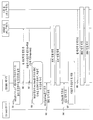
- FIG. 9 is a signal flow diagram illustrating an RRC connection method of the present invention.
- the UE in idle state which wants to receive the MBMS service, applies autonomous priority so that the frequency provided with the MBMS service has the highest priority in step 901, and performs a cell reselection procedure in step 902. Camp-on the MBMS cell providing the desired MBMS service.
- the terminal may receive autonomous priority control information in step 903.
- the autonomous priority control information of the present invention may include an indicator indicating whether to apply autonomous priority and information on a specific connection reason.
- the indicator instructs to allow autonomous priority application and indicates mo-Data as the feature access reason.
- the terminal receives the MBMS service while maintaining autonomous priority as in step 904 until the NAS layer requests an RRC connection for mo-Data.
- the UE when the NAS layer of the UE requests an RRC connection for mo-signalling as shown in step 905, the UE attempts an RRC connection to a cell to be selected while maintaining autonomous priority.
- the terminal when the NAS layer of the terminal requests the RRC connection for the mo-Data as in step 906, the terminal applies the default priority setting as in step 907. That is, after applying a default priority (or signaled priority), which is a frequency priority prior to applying autonomous priority, and performing a cell reselection procedure based on this in step 908, MBMS frequency with congestion Camp-on at a cell of a different frequency.
- a default priority or signaled priority
- the network may adjust the autonomous priority application prohibition rate of the UE attempting RRC access according to the congestion degree.
- the network may deliver the autonomous priority control information together or separately, indicating the autonomous priority application prohibition rate.
- the terminal receiving the RRC connection request from the NAS generates a random number within a certain range, and maintains the autonomous frequency priority when the random number is smaller than the autonomous priority application prohibition rate.
- the terminal if the generated random number is larger than the autonomous priority application prohibition rate, the terminal returns to the previous frequency priority set by the network, that is, the default priority.
- the network can prohibit autonomous priority from a large proportion of UEs attempting RRC access by lowering the autonomous priority prohibition rate when the congestion is high, and by increasing the prohibition rate of priority application when the congestion is relatively low. It is possible to prohibit frequency prioritization of a small proportion of terminals.
- FIG. 10 is a signal flow diagram illustrating an RRC connection method of the present invention.
- the terminal may receive autonomous priority control information in step 1003.
- the autonomous priority control information of the present invention may include an indicator indicating whether to apply autonomous priority and information on a specific connection reason.
- the autonomous priority control information of FIG. 10 includes an autonomous priority application prohibition rate and an autonomous priority prohibition timer.
- the indicator instructs to allow autonomous priority application and indicates mo-Data as the feature access reason. Thereafter, the terminal receives the MBMS service while maintaining autonomous priority as in step 1004 until the NAS layer requests the RRC connection for the mo-Data.
- the terminal when the NAS layer of the terminal requests the RRC connection for the mo-Data as in step 1005, the terminal generates a random number within a certain range, the random number is included in the autonomous priority control information autonomous priority If it is less than the prohibition rate, autonomous frequency priority is maintained. However, if the generated random number is greater than the autonomous priority application prohibition rate, the terminal applies the previous frequency priority set by the network, that is, the default priority setting as shown in step 1006. That is, after applying a default priority (or signaled priority), which is a frequency priority before applying autonomous priority, and performing a cell reselection procedure based on this in step 1007, the MBMS frequency in which congestion occurs Camp-on at a cell of a different frequency.
- a default priority or signaled priority
- the terminal operates the autonomous priority prohibit timer and does not apply the autonomous priority for setting the MBMS frequency as the highest priority while the timer is operating. However, when the autonomous priority prohibit timer expires, the terminal may apply autonomous priority to set the MBMS frequency as the highest priority.
- FIG. 11 illustrates a block diagram of a communication device according to an embodiment of the present invention.
- the communication device 1100 includes a processor 1110, a memory 1120, an RF module 1130, a display module 1140, and a user interface module 1150.
- the communication device 1100 is illustrated for convenience of description and some modules may be omitted. In addition, the communication device 1100 may further include necessary modules. In addition, some modules in the communication device 1100 may be classified into more granular modules.
- the processor 1110 is configured to perform an operation according to the embodiment of the present invention illustrated with reference to the drawings. In detail, the detailed operation of the processor 1110 may refer to the contents described with reference to FIGS. 1 to 10.
- the memory 1120 is connected to the processor 1110 and stores an operating system, an application, program code, data, and the like.
- the RF module 1130 is connected to the processor 1110 and performs a function of converting a baseband signal into a radio signal or converting a radio signal into a baseband signal. To this end, the RF module 1130 performs analog conversion, amplification, filtering and frequency up-conversion, or a reverse process thereof.
- the display module 1140 is connected to the processor 1110 and displays various information.
- the display module 1140 may use well-known elements such as, but not limited to, a liquid crystal display (LCD), a light emitting diode (LED), and an organic light emitting diode (OLED).
- the user interface module 1150 is connected to the processor 1110 and may be configured with a combination of well-known user interfaces such as a keypad and a touch screen.
- Embodiments according to the present invention may be implemented by various means, for example, hardware, firmware, software, or a combination thereof.
- an embodiment of the present invention may include one or more application specific integrated circuits (ASICs), digital signal processors (DSPs), digital signal processing devices (DSPDs), programmable logic devices (PLDs), FPGAs ( field programmable gate arrays), processors, controllers, microcontrollers, microprocessors, and the like.
- ASICs application specific integrated circuits
- DSPs digital signal processors
- DSPDs digital signal processing devices
- PLDs programmable logic devices
- FPGAs field programmable gate arrays
- processors controllers, microcontrollers, microprocessors, and the like.
- an embodiment of the present invention may be implemented in the form of a module, procedure, function, etc. that performs the functions or operations described above.
- the software code may be stored in a memory unit and driven by a processor.
- the memory unit may be located inside or outside the processor, and may exchange data with the processor by various known means.
Landscapes
- Engineering & Computer Science (AREA)
- Computer Networks & Wireless Communication (AREA)
- Signal Processing (AREA)
- Computer Security & Cryptography (AREA)
- Mobile Radio Communication Systems (AREA)
Abstract
La présente invention concerne un procédé permettant d'appliquer une ou plusieurs priorités pour la resélection de cellules par un terminal dans un système de communication sans fil. Plus précisément, le procédé comprend les étapes consistant à définir une première priorité et une seconde priorité ; à appliquer la première priorité à la resélection de cellule ; et à appliquer la seconde priorité à la resélection de cellule si l'établissement d'une connexion avec un réseau est demandé.
Priority Applications (1)
| Application Number | Priority Date | Filing Date | Title |
|---|---|---|---|
| US14/386,585 US9479988B2 (en) | 2012-03-19 | 2013-03-15 | Method for accessing network by terminal in wireless communication system, and device therefor |
Applications Claiming Priority (4)
| Application Number | Priority Date | Filing Date | Title |
|---|---|---|---|
| US201261612399P | 2012-03-19 | 2012-03-19 | |
| US61/612,399 | 2012-03-19 | ||
| US201261614516P | 2012-03-23 | 2012-03-23 | |
| US61/614,516 | 2012-03-23 |
Publications (1)
| Publication Number | Publication Date |
|---|---|
| WO2013141526A1 true WO2013141526A1 (fr) | 2013-09-26 |
Family
ID=49222932
Family Applications (1)
| Application Number | Title | Priority Date | Filing Date |
|---|---|---|---|
| PCT/KR2013/002104 Ceased WO2013141526A1 (fr) | 2012-03-19 | 2013-03-15 | Procédé permettant à un terminal d'accéder à un réseau dans un système de communication sans fil, et dispositif associé |
Country Status (2)
| Country | Link |
|---|---|
| US (1) | US9479988B2 (fr) |
| WO (1) | WO2013141526A1 (fr) |
Cited By (1)
| Publication number | Priority date | Publication date | Assignee | Title |
|---|---|---|---|---|
| WO2015127293A1 (fr) * | 2014-02-21 | 2015-08-27 | Qualcomm Incorporated | Appareil et procédé pour accélérer la re-sélection de technologie d'accès inter-radio |
Families Citing this family (9)
| Publication number | Priority date | Publication date | Assignee | Title |
|---|---|---|---|---|
| KR102093485B1 (ko) * | 2013-02-19 | 2020-03-25 | 삼성전자주식회사 | 패킷 데이터 통신 시스템에서 서비스 억세스 제어를 위한 장치 및 방법 |
| EP3657857B1 (fr) * | 2015-04-10 | 2021-12-01 | Kyocera Corporation | Terminal d'utilisateur |
| KR102316778B1 (ko) | 2015-09-25 | 2021-10-25 | 삼성전자 주식회사 | 공공 안전 서비스를 지원하는 단말이 아이들 모드에서 셀을 재선택하는 방법 및 장치 |
| WO2018034473A1 (fr) * | 2016-08-14 | 2018-02-22 | Samsung Electronics Co., Ltd. | Système et procédé pour opération de comptage de service de diffusion/multidiffusion multimédia (mbms) |
| WO2020153214A1 (fr) * | 2019-01-23 | 2020-07-30 | 京セラ株式会社 | Procédé de commande de resélection de cellule, et équipement utilisateur |
| CN113099483B (zh) * | 2019-12-23 | 2023-07-07 | 维沃移动通信有限公司 | 小区拥塞的处理方法、终端及网络侧设备 |
| CN115843453A (zh) * | 2020-06-29 | 2023-03-24 | 瑞典爱立信有限公司 | 用于处于空闲状态和不活动状态的用户设备的多播和广播服务 |
| CN116017747A (zh) * | 2021-10-21 | 2023-04-25 | 大唐移动通信设备有限公司 | 一种频点优先级的调整方法及装置 |
| US11792712B2 (en) | 2021-12-23 | 2023-10-17 | T-Mobile Usa, Inc. | Cell reselection priority assignment based on performance triggers |
Citations (2)
| Publication number | Priority date | Publication date | Assignee | Title |
|---|---|---|---|---|
| US20110165909A1 (en) * | 2008-09-19 | 2011-07-07 | Zte Corporation | Cell reselection method and terminal |
| US20110250888A1 (en) * | 2010-04-13 | 2011-10-13 | Jin Sook Ryu | Method and apparatus for performing cell reselection in wireless communication system |
Family Cites Families (13)
| Publication number | Priority date | Publication date | Assignee | Title |
|---|---|---|---|---|
| EP1743440B1 (fr) * | 2004-08-05 | 2009-10-07 | LG Electronics, Inc. | Interruption de l'utilisation d'un systeme de convergence de couches de frequence |
| WO2008099341A2 (fr) * | 2007-02-12 | 2008-08-21 | Nokia Corporation | Appareil, procédé et produit de programme informatique fournissant une option de priorité pour l'interfonctionnement de plusieurs technologies d'accès radio |
| WO2009045078A2 (fr) * | 2007-10-05 | 2009-04-09 | Lg Electronics Inc. | Procédé de réalisation de resélection de cellules dans un système de communication sans fil |
| KR20090045039A (ko) * | 2007-10-30 | 2009-05-07 | 엘지전자 주식회사 | 우선순위에 기반한 셀 재선택 방법 |
| US8838089B2 (en) * | 2008-10-20 | 2014-09-16 | Htc Corporation | Method of improving radio resource control connenction establishment in a wireless communication system and related communication device |
| EP2522179B9 (fr) * | 2010-01-08 | 2014-02-26 | InterDigital Patent Holdings, Inc. | Procédé et appareil pour la gestion des priorités de csg en modes repos et connecté |
| US9220028B2 (en) * | 2010-02-12 | 2015-12-22 | Blackberry Limited | Methods and apparatus to perform measurements |
| JP5298062B2 (ja) * | 2010-04-26 | 2013-09-25 | シャープ株式会社 | 移動局装置、通信システム、セル再選択方法および集積回路 |
| CN103098521B (zh) * | 2010-07-14 | 2016-10-26 | 黑莓有限公司 | 异构网络中的空闲模式混合移动性过程 |
| CN106851789B (zh) * | 2010-11-30 | 2020-11-24 | 黑莓有限公司 | 蜂窝电信网络中的小区重选 |
| US9173192B2 (en) * | 2011-03-17 | 2015-10-27 | Qualcomm Incorporated | Target cell selection for multimedia broadcast multicast service continuity |
| CN102740233B (zh) * | 2011-04-08 | 2017-06-06 | 中兴通讯股份有限公司 | 实现多媒体广播多播业务连续性的方法、用户设备及系统 |
| US8688166B2 (en) * | 2011-10-17 | 2014-04-01 | Intel Corporation | Call establishment in highly congested network environment |
-
2013
- 2013-03-15 US US14/386,585 patent/US9479988B2/en not_active Expired - Fee Related
- 2013-03-15 WO PCT/KR2013/002104 patent/WO2013141526A1/fr not_active Ceased
Patent Citations (2)
| Publication number | Priority date | Publication date | Assignee | Title |
|---|---|---|---|---|
| US20110165909A1 (en) * | 2008-09-19 | 2011-07-07 | Zte Corporation | Cell reselection method and terminal |
| US20110250888A1 (en) * | 2010-04-13 | 2011-10-13 | Jin Sook Ryu | Method and apparatus for performing cell reselection in wireless communication system |
Non-Patent Citations (3)
| Title |
|---|
| "Technical Specification Group Radio Access Network Mobility procedures for Home Node B (HNB); Overall description; Stage 2 (Release 10)", 3GPP TS 25.367 V10.0.0, 28 March 2011 (2011-03-28) * |
| "Technical Specification Group Radio Access Network; Evolved Universal Terrestrial Radio Access (E-UTRA) User Equipment (UE) procedures in idle mode (Release 10)", 3GPP TS 36.304 V10.5.0., 14 March 2012 (2012-03-14) * |
| "Technical Specification, E-UTRA and EPC; UE conformance specification; Part 1: Protocol conformance specification (3GPP TS 36.523-1 version 9.7.0 Release 9)", ETSI TS 136 523-1 V9.7.0., 9 March 2012 (2012-03-09) * |
Cited By (1)
| Publication number | Priority date | Publication date | Assignee | Title |
|---|---|---|---|---|
| WO2015127293A1 (fr) * | 2014-02-21 | 2015-08-27 | Qualcomm Incorporated | Appareil et procédé pour accélérer la re-sélection de technologie d'accès inter-radio |
Also Published As
| Publication number | Publication date |
|---|---|
| US20150049662A1 (en) | 2015-02-19 |
| US9479988B2 (en) | 2016-10-25 |
Similar Documents
| Publication | Publication Date | Title |
|---|---|---|
| KR101448661B1 (ko) | 무선 통신 시스템에서 단말이 서비스를 제공받는 방법 및 이를 위한 장치 | |
| WO2018194390A1 (fr) | Procédé de transfert d'informations système pour ue distant par un ue relais dans un système de communication sans fil, et dispositif associé | |
| KR101871720B1 (ko) | 무선 통신 시스템에서 단말의 plmn 정보 선택 방법 및 이를 위한 장치 | |
| WO2013141526A1 (fr) | Procédé permettant à un terminal d'accéder à un réseau dans un système de communication sans fil, et dispositif associé | |
| WO2012138137A2 (fr) | Procédé permettant à un équipement utilisateur de transmettre des informations de préférence de service dans un système de communication sans fil et appareil correspondant | |
| WO2013065995A1 (fr) | Procédé de transmission et de réception d'un signal à et à partir d'un réseau au niveau d'un équipement utilisateur (ue) dans un système de communication sans fil et appareil correspondant | |
| WO2018203633A1 (fr) | Procédé et appareil permettant d'obtenir des informations de système | |
| KR101481595B1 (ko) | 무선 통신 시스템에서 메시지를 송신하는 방법 및 이를 위한 장치 | |
| WO2017026806A1 (fr) | Procédé et appareil permettant de notifier une mise à jour d'informations du système (si), une mise à jour d'interdiction d'accès étendu (eab) et un message de système d'avertissement public (pws) dans un système de communication sans fil | |
| KR101498090B1 (ko) | 무선 통신 시스템에서 단말의 셀 접속 제한 방법 및 이를 위한 장치 | |
| KR101943322B1 (ko) | 무선 통신 시스템에서 단말이 서비스를 제공받는 방법 및 이를 위한 장치 | |
| WO2011159055A2 (fr) | Procédé de transmission d'un message de réponse de comptage pour qu'un terminal indique une zone de service dans un système de communication sans fil, et dispositif associé | |
| WO2012138171A2 (fr) | Procédé pour l'établissement, par un équipement utilisateur, d'une connexion avec un réseau dans un système de communication sans fil et appareil associé | |
| WO2012064076A2 (fr) | Procédé de connexion rrc et dispositif associé dans un système de communication sans fil | |
| WO2015190750A1 (fr) | Procédé et appareil d'indication de l'utilisation d'une zone mbsfn dans un système de communication sans fil | |
| WO2012023733A2 (fr) | Procédé destiné à permettre à un terminal de signaler un résultat de mesure pour un mdt à une station de base dans un système de communication sans fil et dispositif associé | |
| WO2012134099A2 (fr) | Procédé pour la transmission/réception par un équipement d'utilisateur de données dans un système de communication sans fil et appareil associé | |
| WO2016186345A1 (fr) | Procédé pour émettre un signal de découverte afin d'établir une liaison d2d avec un ue relais dans un système de communication sans fil, et appareil associé | |
| WO2015147605A1 (fr) | Procédé et appareil permettant de réaliser une opération d2d dans un système de communication sans fil | |
| WO2013141656A1 (fr) | Procédé et dispositif de stockage d'informations de plmn sur un équipement d'utilisateur dans un système de communication sans fil | |
| WO2018105899A1 (fr) | Procédé de traitement d'informations de système pour système de communication de type machine et dispositif associé | |
| WO2012002766A2 (fr) | Procédé permettant de transmettre un signal à une femtocellule mobile, et d'en recevoir un de celle-ci, dans un système de communication sans fil, et appareil pour la mise en œuvre de ce procédé | |
| EP3117666A1 (fr) | Procédé et appareil destinés à indiquer une omission d'une interdiction de classe d'accès dans un système de communication sans fil | |
| WO2013151279A1 (fr) | Procédé de resélection de cellule par un équipement utilisateur dans un système de communication sans fil et dispositif associé | |
| WO2012134213A2 (fr) | Procédé pour transmettre et recevoir un message dans le but de recevoir la réception d'un service de diffusion dans un système de communication sans fil et appareil correspondant |
Legal Events
| Date | Code | Title | Description |
|---|---|---|---|
| 121 | Ep: the epo has been informed by wipo that ep was designated in this application |
Ref document number: 13763493 Country of ref document: EP Kind code of ref document: A1 |
|
| NENP | Non-entry into the national phase |
Ref country code: DE |
|
| WWE | Wipo information: entry into national phase |
Ref document number: 14386585 Country of ref document: US |
|
| 122 | Ep: pct application non-entry in european phase |
Ref document number: 13763493 Country of ref document: EP Kind code of ref document: A1 |