WO2013144996A1 - 空気調和装置 - Google Patents
空気調和装置 Download PDFInfo
- Publication number
- WO2013144996A1 WO2013144996A1 PCT/JP2012/002100 JP2012002100W WO2013144996A1 WO 2013144996 A1 WO2013144996 A1 WO 2013144996A1 JP 2012002100 W JP2012002100 W JP 2012002100W WO 2013144996 A1 WO2013144996 A1 WO 2013144996A1
- Authority
- WO
- WIPO (PCT)
- Prior art keywords
- heat exchanger
- refrigerant
- side heat
- heat medium
- heat
- Prior art date
- Legal status (The legal status is an assumption and is not a legal conclusion. Google has not performed a legal analysis and makes no representation as to the accuracy of the status listed.)
- Ceased
Links
Images





Classifications
-
- F—MECHANICAL ENGINEERING; LIGHTING; HEATING; WEAPONS; BLASTING
- F25—REFRIGERATION OR COOLING; COMBINED HEATING AND REFRIGERATION SYSTEMS; HEAT PUMP SYSTEMS; MANUFACTURE OR STORAGE OF ICE; LIQUEFACTION SOLIDIFICATION OF GASES
- F25B—REFRIGERATION MACHINES, PLANTS OR SYSTEMS; COMBINED HEATING AND REFRIGERATION SYSTEMS; HEAT PUMP SYSTEMS
- F25B49/00—Arrangement or mounting of control or safety devices
- F25B49/02—Arrangement or mounting of control or safety devices for compression type machines, plants or systems
- F25B49/022—Compressor control arrangements
-
- F—MECHANICAL ENGINEERING; LIGHTING; HEATING; WEAPONS; BLASTING
- F25—REFRIGERATION OR COOLING; COMBINED HEATING AND REFRIGERATION SYSTEMS; HEAT PUMP SYSTEMS; MANUFACTURE OR STORAGE OF ICE; LIQUEFACTION SOLIDIFICATION OF GASES
- F25B—REFRIGERATION MACHINES, PLANTS OR SYSTEMS; COMBINED HEATING AND REFRIGERATION SYSTEMS; HEAT PUMP SYSTEMS
- F25B13/00—Compression machines, plants or systems, with reversible cycle
-
- F—MECHANICAL ENGINEERING; LIGHTING; HEATING; WEAPONS; BLASTING
- F25—REFRIGERATION OR COOLING; COMBINED HEATING AND REFRIGERATION SYSTEMS; HEAT PUMP SYSTEMS; MANUFACTURE OR STORAGE OF ICE; LIQUEFACTION SOLIDIFICATION OF GASES
- F25B—REFRIGERATION MACHINES, PLANTS OR SYSTEMS; COMBINED HEATING AND REFRIGERATION SYSTEMS; HEAT PUMP SYSTEMS
- F25B41/00—Fluid-circulation arrangements
- F25B41/20—Disposition of valves, e.g. of on-off valves or flow control valves
- F25B41/22—Disposition of valves, e.g. of on-off valves or flow control valves between evaporator and compressor
-
- F—MECHANICAL ENGINEERING; LIGHTING; HEATING; WEAPONS; BLASTING
- F25—REFRIGERATION OR COOLING; COMBINED HEATING AND REFRIGERATION SYSTEMS; HEAT PUMP SYSTEMS; MANUFACTURE OR STORAGE OF ICE; LIQUEFACTION SOLIDIFICATION OF GASES
- F25B—REFRIGERATION MACHINES, PLANTS OR SYSTEMS; COMBINED HEATING AND REFRIGERATION SYSTEMS; HEAT PUMP SYSTEMS
- F25B2313/00—Compression machines, plants or systems with reversible cycle not otherwise provided for
- F25B2313/023—Compression machines, plants or systems with reversible cycle not otherwise provided for using multiple indoor units
- F25B2313/0231—Compression machines, plants or systems with reversible cycle not otherwise provided for using multiple indoor units with simultaneous cooling and heating
-
- F—MECHANICAL ENGINEERING; LIGHTING; HEATING; WEAPONS; BLASTING
- F25—REFRIGERATION OR COOLING; COMBINED HEATING AND REFRIGERATION SYSTEMS; HEAT PUMP SYSTEMS; MANUFACTURE OR STORAGE OF ICE; LIQUEFACTION SOLIDIFICATION OF GASES
- F25B—REFRIGERATION MACHINES, PLANTS OR SYSTEMS; COMBINED HEATING AND REFRIGERATION SYSTEMS; HEAT PUMP SYSTEMS
- F25B2313/00—Compression machines, plants or systems with reversible cycle not otherwise provided for
- F25B2313/023—Compression machines, plants or systems with reversible cycle not otherwise provided for using multiple indoor units
- F25B2313/0233—Compression machines, plants or systems with reversible cycle not otherwise provided for using multiple indoor units in parallel arrangements
-
- F—MECHANICAL ENGINEERING; LIGHTING; HEATING; WEAPONS; BLASTING
- F25—REFRIGERATION OR COOLING; COMBINED HEATING AND REFRIGERATION SYSTEMS; HEAT PUMP SYSTEMS; MANUFACTURE OR STORAGE OF ICE; LIQUEFACTION SOLIDIFICATION OF GASES
- F25B—REFRIGERATION MACHINES, PLANTS OR SYSTEMS; COMBINED HEATING AND REFRIGERATION SYSTEMS; HEAT PUMP SYSTEMS
- F25B2313/00—Compression machines, plants or systems with reversible cycle not otherwise provided for
- F25B2313/027—Compression machines, plants or systems with reversible cycle not otherwise provided for characterised by the reversing means
- F25B2313/0272—Compression machines, plants or systems with reversible cycle not otherwise provided for characterised by the reversing means using bridge circuits of one-way valves
-
- F—MECHANICAL ENGINEERING; LIGHTING; HEATING; WEAPONS; BLASTING
- F25—REFRIGERATION OR COOLING; COMBINED HEATING AND REFRIGERATION SYSTEMS; HEAT PUMP SYSTEMS; MANUFACTURE OR STORAGE OF ICE; LIQUEFACTION SOLIDIFICATION OF GASES
- F25B—REFRIGERATION MACHINES, PLANTS OR SYSTEMS; COMBINED HEATING AND REFRIGERATION SYSTEMS; HEAT PUMP SYSTEMS
- F25B2313/00—Compression machines, plants or systems with reversible cycle not otherwise provided for
- F25B2313/027—Compression machines, plants or systems with reversible cycle not otherwise provided for characterised by the reversing means
- F25B2313/02732—Compression machines, plants or systems with reversible cycle not otherwise provided for characterised by the reversing means using two three-way valves
-
- F—MECHANICAL ENGINEERING; LIGHTING; HEATING; WEAPONS; BLASTING
- F25—REFRIGERATION OR COOLING; COMBINED HEATING AND REFRIGERATION SYSTEMS; HEAT PUMP SYSTEMS; MANUFACTURE OR STORAGE OF ICE; LIQUEFACTION SOLIDIFICATION OF GASES
- F25B—REFRIGERATION MACHINES, PLANTS OR SYSTEMS; COMBINED HEATING AND REFRIGERATION SYSTEMS; HEAT PUMP SYSTEMS
- F25B2313/00—Compression machines, plants or systems with reversible cycle not otherwise provided for
- F25B2313/027—Compression machines, plants or systems with reversible cycle not otherwise provided for characterised by the reversing means
- F25B2313/02741—Compression machines, plants or systems with reversible cycle not otherwise provided for characterised by the reversing means using one four-way valve
-
- F—MECHANICAL ENGINEERING; LIGHTING; HEATING; WEAPONS; BLASTING
- F25—REFRIGERATION OR COOLING; COMBINED HEATING AND REFRIGERATION SYSTEMS; HEAT PUMP SYSTEMS; MANUFACTURE OR STORAGE OF ICE; LIQUEFACTION SOLIDIFICATION OF GASES
- F25B—REFRIGERATION MACHINES, PLANTS OR SYSTEMS; COMBINED HEATING AND REFRIGERATION SYSTEMS; HEAT PUMP SYSTEMS
- F25B25/00—Machines, plants or systems, using a combination of modes of operation covered by two or more of the groups F25B1/00 - F25B23/00
- F25B25/005—Machines, plants or systems, using a combination of modes of operation covered by two or more of the groups F25B1/00 - F25B23/00 using primary and secondary systems
-
- F—MECHANICAL ENGINEERING; LIGHTING; HEATING; WEAPONS; BLASTING
- F25—REFRIGERATION OR COOLING; COMBINED HEATING AND REFRIGERATION SYSTEMS; HEAT PUMP SYSTEMS; MANUFACTURE OR STORAGE OF ICE; LIQUEFACTION SOLIDIFICATION OF GASES
- F25B—REFRIGERATION MACHINES, PLANTS OR SYSTEMS; COMBINED HEATING AND REFRIGERATION SYSTEMS; HEAT PUMP SYSTEMS
- F25B2600/00—Control issues
- F25B2600/02—Compressor control
- F25B2600/021—Inverters therefor
-
- F—MECHANICAL ENGINEERING; LIGHTING; HEATING; WEAPONS; BLASTING
- F25—REFRIGERATION OR COOLING; COMBINED HEATING AND REFRIGERATION SYSTEMS; HEAT PUMP SYSTEMS; MANUFACTURE OR STORAGE OF ICE; LIQUEFACTION SOLIDIFICATION OF GASES
- F25B—REFRIGERATION MACHINES, PLANTS OR SYSTEMS; COMBINED HEATING AND REFRIGERATION SYSTEMS; HEAT PUMP SYSTEMS
- F25B2600/00—Control issues
- F25B2600/25—Control of valves
- F25B2600/2513—Expansion valves
-
- Y—GENERAL TAGGING OF NEW TECHNOLOGICAL DEVELOPMENTS; GENERAL TAGGING OF CROSS-SECTIONAL TECHNOLOGIES SPANNING OVER SEVERAL SECTIONS OF THE IPC; TECHNICAL SUBJECTS COVERED BY FORMER USPC CROSS-REFERENCE ART COLLECTIONS [XRACs] AND DIGESTS
- Y02—TECHNOLOGIES OR APPLICATIONS FOR MITIGATION OR ADAPTATION AGAINST CLIMATE CHANGE
- Y02B—CLIMATE CHANGE MITIGATION TECHNOLOGIES RELATED TO BUILDINGS, e.g. HOUSING, HOUSE APPLIANCES OR RELATED END-USER APPLICATIONS
- Y02B30/00—Energy efficient heating, ventilation or air conditioning [HVAC]
- Y02B30/70—Efficient control or regulation technologies, e.g. for control of refrigerant flow, motor or heating
Definitions
- the present invention relates to a multi-room air conditioner used for, for example, a building multi-air conditioner.
- An air conditioner equipped with a multi-room heat pump type refrigeration cycle circuit that is generally used includes a compressor, a four-way valve, and an outdoor heat exchanger as outdoor units, and each includes an expansion valve and an indoor heat as a plurality of indoor units. It has an exchanger. These components are sequentially communicated via a refrigerant pipe to constitute a heat pump type refrigeration cycle. That is, the indoor units are configured in parallel, and a predetermined refrigeration cycle circuit is configured by switching between the cooling operation and the heating operation.
- the refrigerant flow rate of the entire refrigeration cycle circuit is adjusted by adjusting the operating capacity of the compressor with the condensation temperature of the indoor heat exchanger as a target value. ing.
- the refrigerant flow rate of the indoor heat exchanger is adjusted by adjusting the degree of subcooling of the indoor heat exchanger as a target value and adjusting the opening of the expansion valve.
- the capacity of the indoor heat exchanger is designed so as to exert a predetermined heating capacity with respect to the load of the indoor unit by adjusting the condensation pressure and the degree of supercooling within a predetermined range in the heating operation.
- the evaporation pressure and superheat degree are adjusted within a predetermined range.
- any one of the indoor units An air conditioner that performs an air conditioning capability saving operation has been proposed. (For example, refer to Patent Document 1).
- This air conditioner determines whether the capacity of the compressor has reached the maximum capacity during heating operation. When it is determined that the maximum value has been reached, it is determined whether the overall capacity of the system with respect to the heating load is excessive or insufficient based on a value obtained by subtracting the calculated high pressure saturation temperature from the target value of the high pressure saturation temperature.
- the supercooling degree (subcool) target value is set to a larger value in order of lower priority, and the heating capacity saving operation is performed.
- the superheat target value is changed to a larger value.
- an air conditioner capable of simultaneous cooling and heating
- an air conditioner in which a water temperature controller capable of heating water in use in parallel with an indoor unit is connected to a heat source for air conditioning for example, , See Patent Document 2.
- the air conditioner determines that the air conditioning side has insufficient capacity when it is detected that the high pressure is lower than a preset predetermined pressure.
- the control which gives priority to indoor air-conditioning by closing the opening degree of the water use side refrigerant
- the opening degree of the water-use-side refrigerant flow control device is opened to a predetermined opening degree so that the water heating operation can be performed simultaneously with the indoor air conditioning.
- the pressure reducing device that controls the refrigerant flow rate of the indoor unit with a low priority is adjusted to maintain the air conditioning capability of the indoor unit with a high priority, but only the pressure reducing device is adjusted. Then, the subject that the air conditioning capability of the indoor unit with a high priority cannot be enlarged occurred.
- the pressure reducing device that controls the refrigerant flow rate of the low-priority use-side heat exchanger is adjusted to maintain the heat exchange capability of the high-priority use-side heat exchanger.
- the heat exchange capacity of the use side heat exchanger having a high priority cannot be increased only by adjusting the decompression device.
- an air conditioner including a heat exchanger has been proposed.
- an air conditioning apparatus in which a part of the heat exchanger between heat mediums is a condenser, and the remaining part is an evaporator, so that the cold / hot water mixed mode can be implemented.
- the capacity required when the all-indirect indoor heat exchanger is used for heating operation is that the total heat medium heat exchanger functions as a condenser.
- the heating load of the indirect indoor unit in which the indirect indoor heat exchanger is accommodated is sufficiently large.
- the heat transfer area of the heat exchanger between the heat medium functioning as a condenser is small with respect to the heating load, it is only necessary to adjust the condensing temperature to a predetermined range and adjust the expansion device to adjust the heat medium to the heating load.
- the heating medium delivery flow rate of the pump that delivers the heating medium related to heating is insufficient, and the heating capacity of the indirect indoor unit is reduced.
- the present invention has been made to solve at least one of the above-described problems, and when operating with priority given to the heat exchange capability of some of the use side heat exchangers, the use side heat exchangers It aims at obtaining the air conditioning apparatus which can enlarge the heat exchange capability of the.
- An air conditioner includes a compressor, a heat source side heat exchanger that functions as a condenser or an evaporator, a plurality of usage side heat exchangers that function as a condenser or an evaporator, and the usage side heat exchange.
- a plurality of expansion devices that are provided corresponding to the compressor and adjust the flow rate of the refrigerant flowing through the use side heat exchanger, and a control device that controls the operating capacity of the compressor and the openings of the plurality of expansion devices, And increasing the heat exchange capacity of a part of the plurality of use side heat exchangers (hereinafter, the use side heat exchanger that increases the heat exchange capacity is referred to as a first use side heat exchanger).
- the control device increases the operating capacity of the compressor, and is the use side heat exchanger other than the first use side heat exchanger, and has the same function as the first use side heat exchanger.
- the use side heat exchanger (hereinafter referred to as a second use side heat exchanger)
- the flow rate of the refrigerant flowing through the second usage-side heat exchanger is reduced by controlling the opening of the expansion device corresponding to the second usage-side heat exchanger. Is.
- the air conditioner of the present invention increases the operating capacity of the compressor and increases the refrigerant flow rate in the second usage-side heat exchanger when increasing the heat exchange capacity of the first usage-side heat exchanger. .
- the condensation saturation temperature of the refrigerant flowing through the first usage-side heat exchanger can be increased.
- the first usage-side heat exchanger is cooled.
- the evaporation saturation temperature of the refrigerant flowing through the first use side heat exchanger can be lowered. And in this case, it can suppress that the heat exchange capability of a 2nd utilization side heat exchanger becomes excessive. Therefore, when operating with priority on the heat exchange capability of the first user-side heat exchanger, the heat exchange capability of the first user-side heat exchanger can be increased.
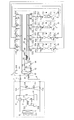
- FIG. 1 is a refrigerant circuit diagram of the air-conditioning apparatus according to Embodiment 1 of the present invention.
- the air conditioner of Embodiment 1 includes a compressor 11, a four-way valve 12 that is a refrigerant flow switching device, an outdoor heat exchanger 13 that is a heat source side heat exchanger, an accumulator 14, and a plurality of use side heat exchangers.
- the indoor heat exchanger 31 and a plurality of expansion valves 32 (expansion devices) provided corresponding to the indoor heat exchangers 31 are connected by piping to constitute a refrigeration cycle circuit.
- the compressor 11 pressurizes and discharges (sends out) the sucked refrigerant.
- the four-way valve 12 serving as the refrigerant flow switching device is provided on the discharge side of the compressor 11 and switches the refrigerant path.
- the four-way valve 12 switches a valve corresponding to an operation mode related to air conditioning based on an instruction from an outdoor controller 202 described later.
- the refrigerant path is switched between the cooling operation and the heating operation.
- the outdoor heat exchanger 13 includes, for example, a heat transfer tube through which a refrigerant passes, a fin (not shown) for increasing the heat transfer area between the refrigerant flowing through the heat transfer tube and the outside air, and a fan 101 that conveys air. And performs heat exchange between the refrigerant and air (outside air).
- the outdoor heat exchanger 13 functions as an evaporator during heating operation, and evaporates the refrigerant to gasify it.
- the outdoor heat exchanger 13 functions as a condenser or a gas cooler (hereinafter referred to as a condenser) during the cooling operation, and condenses and liquefies the refrigerant.
- the gas may not be completely gasified or liquefied, but may be in a two-phase mixed state of gas and liquid (gas-liquid two-phase refrigerant).
- the indoor heat exchanger 31 is, for example, a heat transfer tube that allows refrigerant to pass through, a fin (not shown) for increasing the heat transfer area between the refrigerant flowing through the heat transfer tube and the outside air, and a fan that conveys air (see FIG. (Not shown), and performs heat exchange between the refrigerant and air (inside the room).
- the indoor heat exchanger 31 functions as a condenser or a gas cooler (hereinafter referred to as a condenser) during heating operation, and condenses and liquefies the refrigerant.
- the indoor heat exchanger 31 functions as an evaporator during the cooling operation, and evaporates the refrigerant to gasify it.
- the gas may not be completely gasified or liquefied, but may be in a two-phase mixed state of gas and liquid (gas-liquid two-phase refrigerant).
- the expansion valve 32 such as an electronic expansion valve depressurizes the refrigerant by adjusting the refrigerant flow rate.
- the accumulator 14 functions to store excess refrigerant in the refrigeration cycle circuit and to prevent the compressor 11 from being damaged by returning a large amount of refrigerant liquid to the compressor 11.
- the refrigeration cycle circuit is provided with various pressure sensors and temperature sensors.
- a pressure sensor 71 serving as a refrigerant pressure detecting means is installed between the discharge side of the compressor 11 and the four-way valve 12 and detects a discharge pressure (pressure of the refrigerant discharged from the compressor 11).
- the pressure sensor 72 is installed between the accumulator 14 and the compressor 11 and detects the suction pressure (the pressure of the refrigerant sucked by the compressor 11).
- the pressure sensor 71 and the pressure sensor 72 are not limited as long as the discharge pressure and the suction pressure of the compressor 11 can be detected.
- a temperature sensor 74 that is a refrigerant temperature detecting means is installed in the gas branch pipe 41 that connects the four-way valve 12 and the indoor heat exchanger 31, and detects the gas side temperature of the indoor heat exchanger 31.
- the temperature sensor 75 is installed between the indoor heat exchanger 31 and the expansion valve 32 of each indoor unit and detects the liquid side temperature of the indoor heat exchanger 31.
- the temperature sensor 73 detects the intake air temperature of the indoor heat exchanger 31 (in other words, each indoor unit 2 described later).
- the compressor 11, the four-way valve 12, the outdoor heat exchanger 13, and the accumulator 14 are accommodated in the outdoor unit 1 that is a heat source unit.
- the indoor heat exchanger 31 and the expansion valve 32 are accommodated in the indoor unit 2.
- the indoor unit 2 is connected in parallel to the outdoor unit 1 by a gas pipe 4 and a gas branch pipe 41, a liquid pipe 5 and a liquid branch pipe 42 which are refrigerant pipes.
- FIG. 1 shows the case where there are two indoor units 2, the number of indoor units 2 is arbitrary as long as it is two or more.
- the outdoor unit 1 also includes an outdoor controller 202 that regulates the control of the outdoor unit 1 and the control of the entire air conditioner.
- the indoor unit 2 also houses an indoor controller 203 that controls the indoor unit (see FIG. 2 described later).
- the outdoor controller 202 and the indoor controller 203 correspond to the control device of the present invention.
- the control device is divided into the outdoor controller 202 and the indoor controller 203, but these may be configured as a single unit.
- FIG. 2 is a control circuit diagram of the air-conditioning apparatus according to Embodiment 1 of the present invention.
- an inverter circuit 201 is connected to the outdoor controller 202.
- the outdoor controller 202 includes a microcomputer and its peripheral circuits.
- the inverter circuit 201 outputs AC power having an operation frequency (and voltage) according to a command from the outdoor controller 202 to the motor of the compressor 11.
- the outdoor controller 202 determines the operating frequency (that is, the rotational speed of the compressor 11) to be commanded to the inverter circuit 201 in accordance with the detected pressure detected by the pressure sensors 71 and 72. Details of this determination method will be described later.
- a valve drive circuit 205 is connected to each of the indoor controllers 203.
- the indoor controller 203 includes a microcomputer and its peripheral circuits, and various control commands are supplied from the outdoor controller 202 as serial signals.
- the valve drive circuit 205 sets the opening degree of the expansion valve 32 in response to a command from the indoor controller 203.
- the indoor controller 203 determines the opening degree of the expansion valve 32 in accordance with the request content from the operation unit 204 and the temperature detected by the temperature sensors 73-75. Details of this determination method will be described later.
- refrigerant used in the air conditioner configured as described above examples include single refrigerants such as R-22 and R-134a, pseudo-azeotropic refrigerant mixtures such as R-410A and R-404A, and R-407C.
- Natural refrigerants can be used.
- the level of the pressure in the refrigeration cycle circuit or the like is not determined by the relationship with the reference pressure, but is a high pressure as a relative pressure that can be achieved by compression of the compressor 11, refrigerant flow control of the expansion valve 32, or the like. It shall be expressed as low pressure. The same applies to the temperature level.
- Heating operation A heating operation in which the indoor unit 2 heats the indoor space will be described.
- the refrigerant in the refrigeration cycle circuit flows as indicated by solid arrows in FIG. That is, in the outdoor unit 1, the refrigerant sucked into the compressor 11 is compressed and discharged as a high-pressure gas refrigerant.
- the refrigerant exiting the compressor 11 flows through the four-way valve 12 and further flows into the indoor units 2 through the gas pipe 4 and the gas branch pipe 41.
- the gas refrigerant that has flowed into the indoor unit 2 flows into the indoor heat exchanger 31. Since the indoor heat exchanger 31 functions as a condenser with respect to the refrigerant, the refrigerant passing through the indoor heat exchanger 31 heats and liquefies the air to be heat exchanged (dissipates heat to the air). Thereby, the indoor space is heated.
- the liquid refrigerant flowing out of the indoor heat exchanger 31 is decompressed by the expansion valve 32 and becomes a low-temperature and low-pressure gas-liquid two-phase refrigerant.
- the low-temperature and low-pressure refrigerant flows out of the indoor unit 2 and returns to the outdoor unit 1 through the liquid branch pipe 42 and the liquid pipe 5.
- the refrigerant flowing into the outdoor unit 1 flows into the outdoor heat exchanger 13 and evaporates by exchanging heat with the air, and flows out as a gas refrigerant or a gas-liquid two-phase refrigerant.
- the evaporated refrigerant is sucked into the compressor 11 again via the four-way valve 12 and the accumulator 14.
- the refrigerant in the refrigeration cycle circuit flows as indicated by broken line arrows in FIG. That is, in the outdoor unit 1, the refrigerant sucked into the compressor 11 is compressed and discharged as a high-pressure gas refrigerant.
- the refrigerant exiting the compressor 11 flows through the four-way valve 12 to the outdoor heat exchanger 13 that functions as a condenser.
- the high-pressure gas refrigerant exchanges heat with the outside air conveyed by the fan 101 while passing through the outdoor heat exchanger 13, condenses, flows out as a high-pressure liquid refrigerant, passes through the liquid pipe 5 and the liquid branch pipe 42. It flows into each indoor unit 2 through.
- the refrigerant flowing into the indoor unit 2 expands by adjusting the opening degree of the expansion valve 32, and the low-temperature and low-pressure gas-liquid two-phase refrigerant flows into the indoor heat exchanger 31. Since the indoor heat exchanger 31 functions as an evaporator with respect to the refrigerant, the refrigerant passing through the indoor heat exchanger 31 cools the air to be heat exchanged (absorbs heat from the air) and flows out as a gas refrigerant. . As a result, the indoor space is cooled.
- the refrigerant flowing into the outdoor unit 1 is sucked into the compressor 11 again via the four-way valve 12 and the accumulator 14.
- capacity control that is, rotation speed control
- the rotation speed of the compressor 11 is controlled by a command from the outdoor controller 202.
- the outdoor controller 202 controls the rotation speed of the compressor 11 so that the discharge pressure detected by the pressure sensor 71 becomes a predetermined target value, and adjusts the refrigerant flow rate of the entire refrigeration cycle.
- the outdoor controller 202 controls the rotation speed of the compressor 11 so that the condensation saturation temperature of the refrigerant (hereinafter also simply referred to as the condensation temperature) becomes a predetermined condensation saturation temperature target value, Adjust the refrigerant flow rate for the entire cycle.
- the discharge pressure as the target value is approximately 50 ° C.
- the outdoor controller 202 controls the rotation speed of the compressor 11 so that the suction pressure detected by the pressure sensor 72 becomes a predetermined target value, and adjusts the refrigerant flow rate of the entire refrigeration cycle.
- the outdoor controller 202 controls the rotation speed of the compressor 11 so that the evaporation saturation temperature of the refrigerant (hereinafter also simply referred to as the evaporation temperature) becomes a predetermined evaporation saturation temperature target value, and the refrigeration cycle. Adjust the total refrigerant flow.
- the suction pressure as the target value is about 0 ° C. in terms of the saturation temperature.
- the opening degree of the expansion valve 32 is controlled by a command from the indoor controller 203. Specifically, during heating operation, the degree of supercooling of the indoor heat exchanger 31 is set as a target value to control the opening, and the refrigerant flow rate flowing into each indoor unit 2 is adjusted.
- the calculation method of the degree of supercooling is as follows. The discharge pressure detected by the pressure sensor 71 of the outdoor unit 1 is converted into a condensation temperature which is a saturation temperature in the outdoor controller 202 and transmitted to the indoor controller 203 of each indoor unit.
- the indoor controller 203 calculates the degree of supercooling from the difference between the condensation temperature and the liquid side temperature of the refrigerant detected by the temperature sensor 75.
- the degree of supercooling is preferably about 5 degrees.
- the opening degree is controlled with the degree of superheat of the indoor heat exchanger 31 as a target value, and the flow rate of refrigerant flowing into each indoor unit 2 is adjusted.
- the degree of supercooling is calculated from the difference between the refrigerant gas side temperature detected by the temperature sensor 74 and the refrigerant liquid side temperature detected by the temperature sensor 75 in the indoor controller 203.
- the degree of superheat is preferably about 3 degrees.
- the indoor unit 2 is performing the heating operation at a certain condensation temperature and the degree of supercooling.
- the intake air temperature of the indoor unit 2 is lowered, that is, the load is increased, if the refrigerant flow rate of the indoor heat exchanger 31 is constant without changing the opening degree of the expansion valve 32, the indoor heat exchanger 31 Since the amount of heat exchange increases and more refrigerant condenses, the degree of supercooling increases.
- the opening degree of the expansion valve 32 is increased, the flow rate of the refrigerant condensed in the indoor heat exchanger 31 is increased, so that the degree of supercooling is reduced and approaches the target value. Moreover, since the heat exchange amount of the indoor heat exchanger 31 is increased, the heating capacity of the indoor unit 2 can be further increased.
- the intake air temperature of the indoor unit 2 rises that is, the load decreases
- the opening degree of the expansion valve 32 is reduced, the flow rate of the refrigerant condensed in the indoor heat exchanger 31 is reduced, so that the degree of supercooling increases and approaches the target value.
- the heat exchange amount of the indoor heat exchanger 31 becomes smaller, the heating capacity of the indoor unit 2 can be further reduced. As described above, by controlling the condensation temperature and the degree of supercooling, a predetermined heating capacity can be exhibited with respect to the indoor load.
- a control method when there is a request for increasing the heating capacity from some of the indoor units 2, that is, when the heating capacity of some of the indoor units 2 is increased will be described.
- the operating capacity of the compressor 11 is made larger than usual, and the heating capacity of the indoor unit 2 that has been requested to increase the heating capacity is made larger than the design capacity.
- the refrigerant flow rate is suppressed and the heating capacity is suppressed from becoming excessive.
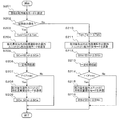
- a flow for changing the values of the condensation temperature target value Tcm and the supercooling degree target value SCm in the case of increasing the heating capacity of the indoor unit 2b will be described along the flowchart of FIG.
- the indoor heat exchanger 31b corresponds to a first user-side heat exchanger.
- the indoor heat exchanger 31a corresponds to a second usage side heat exchanger.
- FIG. 3 is a flowchart showing heating capacity increase control of the air-conditioning apparatus according to Embodiment 1 of the present invention.
- the indoor controller 203b receives a heating capacity increase request from the operation unit 204b of the indoor unit 2b, the indoor controller 203b transmits heating capacity priority to the outdoor controller 202.
- the outdoor controller 202 receives the heating capacity priority
- the outdoor controller 202 starts the flow of FIG. 3 and sets the operation mode of the air conditioner to the capacity priority mode (step S101).
- step S102 the outdoor controller 202 increases the condensation temperature target value Tcm by ⁇ Tcm.
- the rotation speed F of the compressor 11 is controlled based on the condensation temperature Tc. For this reason, if the rotation speed F is less than the rotation speed maximum value Fmax, if the condensation temperature target value Tcm becomes high, the rotation speed F of the compressor 11 will become high.
- step S103 the outdoor controller 202 transmits the capability suppression mode to the indoor units 2 other than capability priority (herein, the indoor unit 2a).
- step S104 the indoor controller 203a of the indoor unit 2a that has received the capability suppression mode increases the subcooling target value SCm of the indoor heat exchanger 31a by ⁇ SCm.
- the opening degree L of the expansion valve 32a is controlled based on the calculated value of the supercooling degree SC, the opening degree L decreases as the supercooling degree target value SCm increases. That is, when the supercooling degree target value SCm of the expansion valve 32a increases, the amount of refrigerant flowing through the indoor unit 2a (more specifically, the indoor heat exchanger 31a) decreases.
- step S105 the outdoor controller 202 makes a fixed time pass.
- the fixed time is, for example, about 3 to 5 minutes.
- step S106 the outdoor controller 202 determines whether or not the rotational speed F of the compressor 11 is less than the maximum value Fmax. If the rotation speed F is less than Fmax (Yes), in step S107, the outdoor controller 202 transmits the refrigerant flow rate increase mode to the capacity-priority indoor unit 2b.
- step S108 the indoor controller 203b that has received the refrigerant flow rate increase mode decreases the subcooling target value SCm of the indoor heat exchanger 31b by ⁇ SCm.
- the opening degree L of the expansion valve 32b is controlled based on the calculated value of the degree of supercooling SC, the degree of opening L increases as the supercooling degree target value SCm decreases. That is, when the supercooling degree target value SCm of the expansion valve 32b decreases, the amount of refrigerant flowing through the indoor unit 2b (more specifically, the indoor heat exchanger 31b) increases.
- step S106 if the rotation speed F is Fmax (No), the flow ends.
- the rotational speed F of the compressor 11 in order to increase the condensation temperature target value Tcm in step S102, the rotational speed F of the compressor 11 has a predetermined heating capacity of the refrigeration cycle. It will be higher than the number of revolutions to achieve. That is, since the refrigerant
- the indoor heat performing the heating operation is increased.
- the heating capacity of all the exchangers 31 is increased, and the capacity increasing effect of the capacity priority indoor unit 2b is reduced. Therefore, in the indoor heat exchanger 31a other than capacity priority, the capacity increase effect of the capacity priority indoor unit 2b can be further increased by increasing the supercooling degree target value SCm.
- step S108 in the capacity priority indoor heat exchanger 31b, the opening degree L of the expansion valve 32b is increased in order to decrease the supercooling degree target value SCm. That is, since the refrigerant
- step S102 when the rotation speed F of the compressor 11 is Fmax, the rotation speed F cannot be increased. However, in this case as well, the refrigerant flowing through the indoor heat exchanger 31a other than capacity priority in step S104.
- the heating capacity of the capacity-priority indoor unit 2b can be increased. For the following reason, when the rotation speed F of the compressor 11 is Fmax in step S106, the supercooling degree target value SCm of the capacity-priority indoor heat exchanger 31b is not changed.
- the refrigerant flow rate is increased by decreasing the superheat degree target value SHm of the indoor heat exchanger 31 by ⁇ SHm.
- the refrigerant flow rate can be reduced by increasing the superheat degree target value SHm by ⁇ SHm.
- Embodiment 2 FIG.
- the air conditioner shown in Embodiment 1 selects the same mode (either heating operation or cooling operation) as the operation mode of each indoor unit 2.
- the present invention is not limited to this, and the present invention can also be implemented in an air conditioner that can individually select the operation mode of each indoor unit, that is, an air conditioner capable of simultaneous cooling and heating.
- the same components as those in the first embodiment are denoted by the same reference numerals, and the points not particularly mentioned are the same as those in the first embodiment.
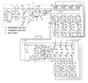
- FIG. 4 is a refrigerant circuit diagram of the air-conditioning apparatus according to Embodiment 2 of the present invention.
- the air conditioner according to the second embodiment accommodates check valves 15a, 15b, 15c, and 15d in the outdoor unit 1.
- the air conditioning apparatus according to Embodiment 2 includes a repeater 3.
- the relay unit 3 includes a gas-liquid separator 51, internal heat exchangers 52 and 53, expansion valves 54 and 55, electromagnetic valves 56 and 57 as opening / closing devices, check valves 58 and 59, pressure sensors 76 and 77, A repeater controller 206 and the like are accommodated.
- the repeater 3 is connected to the outdoor unit 1 through a high-pressure pipe 6 and a low-pressure pipe 7 that are refrigerant pipes.
- Each indoor unit 2 is connected in parallel to the relay unit 3 by a gas branch pipe 41 and a liquid branch pipe 42 which are refrigerant pipes.
- the number of indoor units 2 and repeaters 3 is arbitrary.
- the check valve 15 a is provided between the outdoor heat exchanger 13 and the high-pressure pipe 6 and allows refrigerant to flow only from the outdoor heat exchanger 13 toward the high-pressure pipe 6.
- the check valve 15 b is provided between the low-pressure pipe 7 and the four-way valve 12 and allows the refrigerant to flow only from the low-pressure pipe 7 to the four-way valve 12.
- the check valve 15 c is provided between the four-way valve 12 and the high-pressure pipe 6 and allows the refrigerant to flow only from the four-way valve 12 to the high-pressure pipe 6.
- the check valve 15 d is provided between the low pressure pipe 7 and the outdoor heat exchanger 13 and allows the refrigerant to flow only from the low pressure pipe 7 to the outdoor heat exchanger 13.
- the electromagnetic valves 56 and 57 are configured to switch the gas branch pipe 41 of the indoor unit 2 to the high pressure gas pipe 61 or the low pressure pipe 7 for connection.
- the electromagnetic valve 56 is opened and the electromagnetic valve 57 is closed, the gas branch pipe 41 and the high-pressure gas pipe 61 are connected.
- the electromagnetic valve 57 is opened and the electromagnetic valve 56 is closed, the gas branch pipe 41 and the low-pressure pipe 7 are connected.
- One ends of the check valves 58 and 59 are connected to the liquid branch pipe 42 in an antiparallel relationship.
- the other end of the check valve 58 is connected to the liquid pipe 63 and allows the refrigerant to flow only from the liquid pipe 63 toward the liquid branch pipe 42.
- the other end of the check valve 59 is connected to the liquid pipe 64 and allows the refrigerant to flow only in the direction from the liquid branch pipe 42 to the liquid pipe 64.
- the gas-liquid separator 51 separates the gas and the liquid and flows the gas refrigerant to the high-pressure gas pipe 61 and the liquid refrigerant to the liquid pipe 62.
- the expansion valve 54 is provided between the gas-liquid separator 51 and the liquid pipes 63 and 64.
- the bypass pipe 65 connects the liquid pipe 63 and the low pressure pipe 7.
- the expansion valve 55 is provided in the middle of the bypass pipe 65.
- the internal heat exchanger 53 performs heat exchange between the downstream portion of the expansion valve 55 of the bypass pipe 65 and the pipe extending from the expansion valve 54 to the liquid pipe 63.
- the internal heat exchanger 52 performs heat exchange between the downstream portion of the internal heat exchanger 53 of the bypass pipe 65 and the pipe connecting the gas-liquid separator 51 and the expansion valve 54.
- the relay machine controller 206 controls (commands) the opening of the expansion valves 54 and 55 and the opening and closing of the electromagnetic valves 56 and 57.
- the pressure sensor 76 which is a refrigerant pressure detecting means detects high pressure
- the pressure sensor 77 which is a refrigerant pressure detecting means detects intermediate pressure (pressure between high pressure and low pressure).
- FIG. 4 (All heating operation) In FIG. 4, the heating only operation will be described.
- the flow of the refrigerant is indicated by solid line arrows in FIG.
- the refrigerant sucked into the compressor 11 is compressed and discharged as a high-pressure gas refrigerant.
- the refrigerant that has exited the compressor 11 flows through the four-way valve 12 and then flows out of the outdoor unit 1 through the check valve 15 c and the high-pressure pipe 6.
- the refrigerant that has flowed into the relay unit 3 flows into each indoor unit 2 through the gas-liquid separator 51, the high-pressure gas pipe 61, the electromagnetic valve 56, and the gas branch pipe 41.
- the gas refrigerant flowing into the indoor unit 2 flows into the indoor heat exchanger 31 and heats it.
- the liquid refrigerant that has flowed out of the indoor heat exchanger 31 is decompressed to an intermediate pressure by the expansion valve 32, and becomes an intermediate-pressure liquid refrigerant.
- the intermediate-pressure liquid refrigerant flows out of the indoor unit 2, passes through the liquid branch pipe 42 and the check valve 59, joins in the liquid pipe 64, enters the bypass pipe 65 from here through the internal heat exchanger 53, It flows into the expansion valve 55 and is depressurized to a low-temperature low-pressure gas-liquid two-phase state.
- the decompressed refrigerant passes through the bypass pipe 65, the internal heat exchanger 53, and the internal heat exchanger 52, and then returns to the outdoor unit 1 through the low pressure pipe 7.
- the refrigerant flowing into the outdoor unit 1 passes through the check valve 15d, flows into the outdoor heat exchanger 13 and evaporates by exchanging heat with air, and flows out as a gas refrigerant or a gas-liquid two-phase refrigerant.
- the evaporated refrigerant is sucked into the compressor 11 again via the four-way valve 12 and the accumulator 14.
- the check valves 15a and 15b have a refrigerant. Does not flow. Further, the electromagnetic valve 57 is closed.
- FIG. 4 (Cooling only) In FIG. 4, the cooling operation will be described.
- the flow of the refrigerant is indicated by the dashed arrows in FIG.
- the refrigerant sucked into the compressor 11 is compressed and discharged as a high-pressure gas refrigerant.
- the refrigerant leaving the compressor 11 flows through the four-way valve 12 to the outdoor heat exchanger 13 that functions as a condenser, condenses, flows out as high-pressure liquid refrigerant, passes through the check valve 15 a and the high-pressure pipe 6.
- the outdoor unit 1 flows out.
- the refrigerant flowing into the relay unit 3 passes through the gas-liquid separator 51, the liquid pipe 62, the internal heat exchanger 52, the expansion valve 54, and the internal heat exchanger 53 in this order, and is divided in the liquid pipe 63.
- the divided refrigerant flows into the indoor units 2 through the check valve 58 and the liquid branch pipe 42.
- the refrigerant that has flowed into the indoor unit 2 expands by adjusting the opening degree of the expansion valve 32, and the low-temperature and low-pressure gas-liquid two-phase refrigerant flows into the indoor heat exchanger 31 and cools it.
- the gas refrigerant that has flowed out exits the indoor unit 2 merges through the gas branch pipe 41 and the electromagnetic valve 57, passes through the low pressure pipe 7, and returns to the outdoor unit 1.
- the refrigerant that has flowed into the outdoor unit 1 is sucked into the compressor 11 again via the check valve 15b, the four-way valve 12, and the accumulator 14.
- the high pressure pipe 6 is high pressure
- the pressure between the compressor 11 and the check valve 15c is low
- the high pressure is between the outdoor heat exchanger 13 and the check valve 15d
- the low pressure pipe 7 is low pressure.
- No refrigerant flows through the valves 15c and 15d.
- the electromagnetic valve 56 is closed.
- a part of the refrigerant that has passed through the expansion valve 54 flows into the bypass pipe 65 and is decompressed by the expansion valve 55, and is transferred from the liquid pipe 63 to each indoor unit 2 in the internal heat exchanger 53. Heat exchange is performed with the refrigerant flowing in. Further, in the internal heat exchanger 52, heat exchange is performed with the refrigerant flowing into the expansion valve 54.
- the refrigerant evaporated by heat exchange in the internal heat exchanger 52 merges with the refrigerant cooled in the indoor unit 2 in the low pressure pipe 7 and returns to the outdoor unit 1.
- the refrigerant that is cooled by heat exchange in the internal heat exchanger 52 and the internal heat exchanger 53 and has a sufficient degree of supercooling flows into the indoor unit 2 via the check valve 58 and the liquid branch pipe 42. .
- FIG. 5 is a refrigerant circuit diagram illustrating a heating main operation of the air-conditioning apparatus according to Embodiment 2 of the present invention.
- the indoor units 2a, 2b, and 2c perform the heating operation and the indoor unit 2d performs the cooling operation.
- the outdoor unit 1 the refrigerant sucked into the compressor 11 is compressed and discharged as a high-pressure gas refrigerant.
- the refrigerant that has exited the compressor 11 flows through the four-way valve 12 and then flows out of the outdoor unit 1 through the check valve 15 c and the high-pressure pipe 6.
- the refrigerant flowing into the relay unit 3 passes through the gas-liquid separator 51 and the high-pressure gas pipe 61, passes through the electromagnetic valves 56a, 56b, and 56c, and the gas branch pipes 41a, 41b, and 41c. Flows into 2b and 2c.
- the gas refrigerant that has flowed into the indoor units 2a, 2b, and 2c flows into the indoor heat exchangers 31a, 31b, and 31c and is heated.
- the liquid refrigerant that has flowed out of the indoor heat exchangers 31a, 31b, and 31c is reduced to an intermediate pressure by the expansion valves 32a, 32b, and 32c, and becomes an intermediate-pressure liquid refrigerant.
- the intermediate-pressure liquid refrigerant flows out of the indoor units 2a, 2b, and 2c, passes through the liquid branch pipes 42a, 42b, and 42c, and the check valves 59a, 59b, and 59c, and then joins in the liquid pipe 64.
- the combined intermediate-pressure liquid refrigerant passes through the internal heat exchanger 53, and partly flows into the indoor unit 2d through the liquid pipe 63, the check valve 58d, and the liquid branch pipe 42d.
- the refrigerant that has flowed into the indoor unit 2d expands by adjusting the opening of the expansion valve 32d, and the low-temperature and low-pressure gas-liquid two-phase refrigerant flows into the indoor heat exchanger 31d and cools it.
- the gas refrigerant that has flowed out exits the indoor unit 2d, passes through the gas branch pipe 41d and the electromagnetic valve 57d, and reaches the low-pressure pipe 7.
- the refrigerant flowing into the outdoor unit 1 passes through the check valve 15d, flows into the outdoor heat exchanger 13 and evaporates by exchanging heat with air, and flows out as a gas refrigerant or a gas-liquid two-phase refrigerant.
- the evaporated refrigerant is sucked into the compressor 11 again via the four-way valve 12 and the accumulator 14.
- the check valves 15a and 15b have a refrigerant. Does not flow.
- the electromagnetic valves 56d, 57a, 57b, and 57c are closed.
- the refrigerant entering the bypass pipe 65 is decompressed by the expansion valve 55 and then exchanges heat with the refrigerant flowing in from the liquid pipe 64 in the internal heat exchanger 53.
- the refrigerant flowing into the indoor unit 2d through the stop valve 58d and the liquid branch pipe 42d is cooled and sufficiently subcooled.
- FIG. 6 is a refrigerant circuit diagram illustrating a cooling main operation of the air-conditioning apparatus according to Embodiment 2 of the present invention.
- the indoor units 2a, 2b, and 2c perform the cooling operation and the indoor unit 2d performs the heating operation.
- the outdoor unit 1 the refrigerant sucked into the compressor 11 is compressed and discharged as a high-pressure gas refrigerant.
- the refrigerant that has exited the compressor 11 flows through the four-way valve 12 to the outdoor heat exchanger 13 that functions as a condenser, and is condensed in an arbitrary amount to flow out as a high-pressure gas-liquid two-phase refrigerant.
- the outdoor unit 1 flows out through the high-pressure pipe 6.
- the refrigerant flowing into the relay unit 3 flows into the gas-liquid separator 51 and is separated into a gas refrigerant and a liquid refrigerant.
- the separated gas refrigerant passes through the high-pressure gas pipe 61, passes through the electromagnetic valve 56d and the gas branch pipe 41d, and flows into the indoor unit 2d that performs the heating operation.
- the gas refrigerant that has flowed into the indoor unit 2d flows into the indoor heat exchanger 31d to be heated.
- the liquid refrigerant that has flowed out of the indoor heat exchanger 31d is decompressed to an intermediate pressure by the expansion valve 32d, and becomes an intermediate-pressure liquid refrigerant.
- the intermediate-pressure liquid refrigerant flows out of the indoor unit 2d, passes through the liquid branch pipe 42d and the check valve 59d, and then reaches the liquid pipe 64.
- the liquid refrigerant separated by the gas-liquid separator 51 flows out from the liquid pipe 62, and the difference between the high pressure of the internal heat exchanger 52 and the high pressure pipe 6 and the intermediate pressure that is the pressure of the liquid pipes 63 and 64.
- the indoor unit 2d is heated through the expansion valve 54 that is controlled so as to be constant, and merges with the liquid refrigerant passing through the liquid pipe 64.
- the merged liquid refrigerant passes through the internal heat exchanger 53, partly flows into the liquid pipe 63, passes through the check valves 58a, 58b, 58c, and the liquid branch pipes 42a, 42b, 42c, and the indoor units 2a, Flows into 2b and 2c.
- the refrigerant flowing into the indoor units 2a, 2b, 2c expands by adjusting the opening degree of the expansion valves 32a, 32b, 32c, and the low-temperature and low-pressure gas-liquid two-phase refrigerant flows into the indoor heat exchangers 31a, 31b, 31c. Then cool.
- the refrigerant that has flowed into the outdoor unit 1 is sucked into the compressor 11 again via the check valve 15b, the four-way valve 12, and the accumulator 14.
- the high pressure pipe 6 is high pressure
- the pressure between the compressor 11 and the check valve 15c is low
- the high pressure is between the outdoor heat exchanger 13 and the check valve 15d
- the low pressure pipe 7 is low pressure.
- No refrigerant flows through the valves 15c and 15d.
- the electromagnetic valves 56a, 56b, 56c, 57d are closed.
- the other part of the refrigerant in the liquid pipe 63 flows into the bypass pipe 65 and is depressurized by the expansion valve 55, and in the internal heat exchanger 53, from the liquid pipe 63 to the indoor units 2a and 2b. , 2c, heat exchange is performed with the refrigerant flowing in.
- the internal heat exchanger 52 heat exchange is performed with the refrigerant flowing into the expansion valve 54.
- the refrigerant evaporated by heat exchange in the internal heat exchanger 52 joins with the refrigerant cooled in the indoor units 2a, 2b, and 2c in the low-pressure pipe 7 and returns to the outdoor unit 1.
- the refrigerant cooled by heat exchange in the internal heat exchanger 52 and the internal heat exchanger 53 and having a sufficient degree of supercooling passes through the check valves 58a, 58b, 58c and the liquid branch pipes 42a, 42b, 42c. And flows into the indoor units 2a, 2b, 2c.
- the heating operation and the cooling operation are the same as those in the first embodiment.
- the outdoor controller 202 controls the rotation speed of the compressor 11 with the discharge pressure detected by the pressure sensor 71 as a target value, and adjusts the refrigerant flow rate of the entire refrigeration cycle circuit. That is, in order to give priority to the heating operation, the condensing temperature for exerting a predetermined heating capability is adjusted in the indoor unit 2 that performs the heating operation by controlling the rotation speed of the compressor 11.
- the evaporation temperature is adjusted by the heat exchange amount adjusting means of the outdoor heat exchanger 13 for the indoor unit 2 that performs the cooling operation.
- the heat exchange amount adjusting means is, for example, the rotation speed adjusting means of the fan 101, the heat transfer area adjusting means for closing a part of the heat transfer pipe of the outdoor heat exchanger 13, or the refrigerant flowing through the outdoor heat exchanger 13.
- Bypass means for bypassing a part of By reducing the rotation speed of the fan 101 or by bypassing a part of the refrigerant, the thermal conductance of the outdoor heat exchanger 13 is reduced, and the heat transfer area is reduced by closing a part of the heat transfer tube.
- the temperature difference between the outside air temperature of the outdoor heat exchanger 13 and the evaporation temperature of the refrigerant increases, and the evaporation temperature decreases. Further, from the state in which the heat exchange amount adjusting means is operating, the thermal conductance of the outdoor heat exchanger 13 is increased by increasing the rotational speed of the fan 101 or reducing the bypass amount of a part of the refrigerant, Since the heat transfer area is increased by opening some of the closed heat transfer tubes, the evaporation temperature is increased.
- the outdoor controller 202 controls the rotation speed of the compressor 11 with the suction pressure detected by the pressure sensor 72 as a target value, and performs the cooling operation in the indoor unit 2.
- the evaporating temperature for exhibiting a predetermined cooling capacity is adjusted.
- the condensation temperature is adjusted by the heat exchange amount adjusting means of the outdoor heat exchanger 13.
- the thermal conductance of the outdoor heat exchanger 13 is reduced or the heat transfer area is reduced, the difference between the refrigerant condensation temperature and the outside air temperature of the outdoor heat exchanger 13 is increased and the condensation temperature is increased. .
- the thermal conductance of the outdoor heat exchanger 13 is increased or the heat transfer area is increased, the condensation temperature is lowered.
- ⁇ Capacity increase control method for some indoor units during simultaneous cooling and heating> In the air conditioner of Embodiment 2, when there is a capacity increase request (air conditioning capacity increase request) from a certain part of the indoor units 2, that is, control when increasing the air conditioning capacity of a part of the indoor units 2 A method will be described.
- the capacity increase control is performed for either the heating capacity increase control or the cooling capacity increase control.
- a capacity increase request is made from the indoor unit 2b will be described.
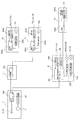
- FIG. 7 is a flowchart showing the capacity increase control of the air-conditioning apparatus according to Embodiment 2 of the present invention.
- the indoor controller 203b receives a capability increase request from the operation unit 204b of the indoor unit 2b
- the indoor controller 203b transmits the capability priority to the outdoor controller 202.
- the outdoor controller 202 receives the capacity priority
- the outdoor controller 202 starts the flow of FIG. 7 and sets the operation mode of the air conditioner to the capacity priority mode (step S201).
- step S202 if the operation mode of the indoor unit 2b is the heating operation (Yes), the outdoor controller 202 performs steps S203 to S209. If the operation mode of the indoor unit 2b is the cooling operation (No), the outdoor controller 202 performs steps S210 to S216.
- step S203 the outdoor controller 202 increases the condensation temperature target value Tcm by ⁇ Tcm.
- the rotation speed F of the compressor 11 is controlled based on the condensation temperature Tc. For this reason, if the rotation speed F is less than the rotation speed maximum value Fmax, if the condensation temperature target value Tcm becomes high, the rotation speed F of the compressor 11 will become high.
- the outdoor heat exchanger 13 has the heat exchange amount adjusting means controlled based on the condensation temperature Tc.
- the heat exchange amount adjusting means of the outdoor heat exchanger 13 is in an operable range (for example, if the rotation speed of the fan 101 is not the minimum value), the heat exchange amount adjusting means is increased when the condensation temperature target value Tcm becomes high. Operates to reduce the thermal conductance of the outdoor heat exchanger 13.
- step S204 the outdoor controller 202 transmits the capability suppression mode to the indoor unit 2 in the heating operation among the indoor units 2a, 2c, and 2d other than the capability priority.
- step S205 the indoor controller 203 of the indoor unit 2 that has received the capability suppression mode increases the supercooling degree target value SCm of the indoor heat exchanger 31 by ⁇ SCm.
- the opening degree L of the expansion valve 32 is controlled based on the calculated value of the degree of supercooling SC, the degree of opening L decreases as the supercooling degree target value SCm increases.
- the outdoor controller 202 determines whether or not the rotation speed F of the compressor 11 is less than the maximum value Fmax in step S207 after a predetermined time has elapsed in step S206. If the rotation speed F is less than Fmax (Yes), in step S208, the outdoor controller 202 transmits the refrigerant flow rate increase mode to the capacity priority indoor unit 2b. In step S209, the indoor controller 203b that has received the refrigerant flow rate increase mode decreases the supercooling degree target value SCm of the indoor heat exchanger 31b by ⁇ SCm. At this time, since the opening degree L of the expansion valve 32b is controlled based on the calculated value of the degree of supercooling SC, the degree of opening L increases as the supercooling degree target value SCm decreases.
- step S207 if the rotation speed F is Fmax (No), the flow ends.
- step S210 the outdoor controller 202 lowers the evaporation temperature target value Tem by ⁇ Tem.
- the rotation speed F of the compressor 11 is controlled based on the evaporation temperature Te. For this reason, if the rotation speed F is less than the rotation speed maximum value Fmax, the rotation speed F of the compressor 11 increases when the evaporation temperature target value Tem decreases.
- the outdoor heat exchanger 13 has the heat exchange amount adjusting means controlled based on the evaporation temperature Te.
- the heat exchange amount adjusting means of the outdoor heat exchanger 13 is in an operable range (for example, if the rotation speed of the fan 101 is not the minimum value), the heat exchange amount adjusting means is reduced when the evaporation temperature target value Tem becomes low. Operates to reduce the thermal conductance of the outdoor heat exchanger 13.
- step S211 the outdoor controller 202 transmits the capability suppression mode to the indoor unit 2 in the cooling operation among the indoor units 2a, 2c, and 2d other than the capability priority.
- the indoor controller 203 of the indoor unit 2 that has received the capability suppression mode increases the superheat degree target value SHm of the indoor heat exchanger 31 by ⁇ SHm in step S212.
- the expansion valve 32 controls the opening degree L based on the calculated value of the superheat degree SH, the opening degree L decreases as the superheat degree target value SHm increases.
- the outdoor controller 202 determines whether or not the rotation speed F of the compressor 11 is less than the maximum value Fmax in step S214 after a predetermined time has elapsed in step S213. If the rotation speed F is less than Fmax (Yes), in step S215, the outdoor controller 202 transmits the refrigerant flow rate increase mode to the capacity priority indoor unit 2b. In step S216, the indoor controller 203b that has received the refrigerant flow rate increase mode decreases the superheat degree target value SHm of the indoor heat exchanger 31b by ⁇ SHm. At this time, since the opening degree L of the expansion valve 32b is controlled based on the calculated value of the superheat degree SH, the opening degree L increases as the superheat degree target value SHm decreases.
- step S214 if the rotation speed F is Fmax (No), the flow ends.
- the operation mode of the entire air conditioner is any one of the heating only operation, the cooling only operation, the heating main operation, and the cooling main operation. Even if the operation mode of the indoor units 2 is either the heating operation or the cooling operation, the air conditioning capability of some of the indoor units 2 can be increased. That is, the capacity of some of the indoor units 2 can be increased regardless of the operation mode of the air conditioner and the operation mode of the indoor units 2.
- Embodiment 3 FIG.
- the air conditioner that performs cooling and heating by circulating the refrigerant directly through the indoor unit 2 has been described.
- an embodiment of an air conditioner that connects a unit that circulates a heat medium to the indoor unit 2 by exchanging heat between a heat medium such as water and a refrigerant in a heat exchanger between heat mediums will be described.
- Embodiment 3 shows an embodiment of an air conditioner including an indirect indoor unit (indirect indoor heat exchanger) that performs indoor air conditioning using a heat medium.
- the same components as those in the first embodiment or the second embodiment are denoted by the same reference numerals, and the points not particularly mentioned are the same as those in the first embodiment or the second embodiment. To do.
- FIG. 8 is a refrigerant circuit diagram of the air-conditioning apparatus according to Embodiment 3 of the present invention.
- the air conditioner according to the third embodiment is obtained by adding the heat medium relay unit 8 and the indoor units 2e, 2f, 2g, and 2h to the configuration of the air conditioner described in the second embodiment.
- This heat medium relay unit 8 includes heat medium heat exchangers 81 and 82, four-way valves 83 and 84, expansion valves 85, 86 and 87, an internal heat exchanger 88, pumps 91 and 92 as heat medium delivery means, The three-way valves 93 and 94 as the heat medium flow switching means, the flow rate adjusting valve 95 as the heat medium flow rate adjusting means, and the heat medium relay controller 207 are accommodated.
- the indoor units 2e, 2f, 2g, and 2h accommodate indoor heat exchangers 31e, 31f, 31g, and 31h.
- the number of the heat medium relay unit 8 and the indoor unit 2 is arbitrary.
- the heat medium relay unit 8 connects the high pressure gas pipe 66 and the high pressure gas pipe 61, connects the liquid pipe 67 and the liquid pipe 64, connects the low pressure pipe 68 and the low pressure pipe 7, Piping is connected.
- Each of the heat medium relay unit 8 and the indoor unit 2 (each of the indoor heat exchanger 31) is connected by heat medium pipes 111 and 112 through which a safe heat medium such as water and antifreeze liquid flows. That is, each of the heat medium relay unit 8 and the indoor unit 2 (each of the indoor heat exchangers 31) is connected by the heat medium path.
- the indoor heat exchangers 31a, 31b, 31c, and 31d are connected to each other by the relay 3 and the gas branch pipe 41 and the liquid branch pipe 42 that are refrigerant pipes, the indoor heat exchangers 31a, 31b, 31c, and 31d are connected.
- the refrigerant circulates directly and performs air conditioning. That is, the indoor heat exchangers 31a, 31b, 31c, and 31d are direct expansion heat exchangers, and the indoor units 2a, 2b, 2c, and 2d are direct expansion indoor units.
- the indoor units 2e, 2f, 2g, and 2h are connected to each other by the heat medium relay unit 8 and the heat medium pipes 111 and 112, the heat medium circulates in the indoor heat exchangers 31e, 31f, 31g, and 31h. Air conditioning. That is, the indoor heat exchangers 31e, 31f, 31g, and 31h are indirect heat exchangers, and the indoor units 2e, 2f, 2g, and 2h are indirect indoor units.
- FIG. 9 is a control circuit diagram of the air-conditioning apparatus according to Embodiment 3 of the present invention.
- the heat medium relay unit 8 includes a heat medium relay unit controller 207, to which a valve drive circuit 209 and a pump drive circuit 210 are connected.
- the heat medium relay controller 207 includes a microcomputer and its peripheral circuits, and various control commands are supplied from the outdoor controller 202 as serial signals.
- the repeater controller 206 communicates with the indoor controllers 203a, 203b, 203c, and 203d of the indoor units 2a, 2b, 2c, and 2d connected to the repeater 3, and the repeater controller 206 communicates with the indoor units 2a and 2b. , 2c, 2d are integrated and communicated with the outdoor controller 202.
- the heat medium relay controller 207 communicates with the indoor controllers 203e, 203f, 203g, and 203h of the indoor units 2e, 2f, 2g, and 2h connected to the heat medium relay 8 by piping, and the heat medium relay controller 207 Integrates the operation information of the indoor units 2e, 2f, 2g, and 2h and communicates with the outdoor controller 202. In FIG. 9, only the indoor unit 2e and its indoor controller 203e are shown.
- the heat exchangers 81 and 82 include a heat transfer section that allows the refrigerant to pass therethrough and a heat transfer section that allows the heat medium to pass therethrough, and performs heat exchange between the medium using the refrigerant and the heat medium.
- the heat exchangers 81 and 82 are configured to heat the heat medium by dissipating heat to the refrigerant as a condenser and to heat the heat medium to be absorbed by the refrigerant as an evaporator depending on the operation mode of the indoor unit 2 that is an indirect indoor unit. May be cooled.
- the pumps 91 and 92 are pressurized to circulate the heat medium.
- the flow rate (discharge flow rate) for sending the heat medium can be changed by changing the rotation speed of a built-in motor (not shown) within a certain range.
- the three-way valve 93 is connected to the heat medium pipe 111 by switching the heat medium pipe 115 or the heat medium pipe 116.
- the three-way valve 94 is connected to the heat medium pipe 112 by switching the heat medium pipe 113 or the heat medium pipe 114.
- the flow rate adjusting valves 95 each adjust the flow rate of the heat medium flowing into the indoor unit 2.
- the outdoor unit 1 and the relay unit 3 are connected by a high pressure pipe 6 and a low pressure pipe 7 which are refrigerant pipes. Further, the relay unit 3 and the indoor unit 2 are connected by a gas branch pipe 41 and a liquid branch pipe 42 which are refrigerant pipes.
- the refrigeration cycle circuit is provided with various pressure sensors and temperature sensors.
- the pressure sensor 138 detects the condensation pressure when the heat exchangers 81 and 82 function as a condenser. However, the pressure sensor 138 should just be a position which can detect the condensation pressure of the heat exchangers 81 and 82 between heat media.
- the temperature sensor 131 is installed between the four-way valve 83 and the heat exchanger 81
- the temperature sensor 132 is installed between the heat exchanger 81 and the expansion valve 85
- the temperature sensor 133 is the four-way valve.
- the temperature sensor 134 is installed between the heat exchanger related to heat medium 82 and the expansion valve 86, and detects the temperature of the refrigerant.
- the temperature sensor 135 is installed in the heat medium pipe 115 and detects the temperature of the heat medium flowing out of the heat exchanger related to heat medium 81.
- the temperature sensor 136 is installed in the heat medium pipe 116 and detects the temperature of the heat medium flowing out from the intermediate heat exchanger 82.
- the temperature sensor 137 is installed in the heat medium pipe 112 and detects the temperature of the heat medium flowing out from each indoor unit 2 serving as an indirect indoor unit.
- the refrigerant flow is indicated by a solid line arrow without tip filling
- the heat medium flow is indicated by a broken line arrow with tip filling.
- the four-way valve 83 connects the high-pressure gas pipe 66 and the heat exchanger related to heat medium 81 by piping.
- the four-way valve 84 connects the high-pressure gas pipe 66 and the heat exchanger related to heat medium 82 by piping.
- the three-way valve 93 has an intermediate opening so that the heat medium flowing through the heat medium pipe 115 and the heat medium flowing through the heat medium pipe 116 are mixed and flow to the heat medium pipe 111.
- the three-way valve 94 has an intermediate opening so that the heat medium flowing through the heat medium pipe 112 is divided into the heat medium pipe 113 and the heat medium pipe 114.
- the gas refrigerant that has flowed into the heat medium relay unit 8 through the high-pressure gas pipe flows into the heat exchangers 81 and 82 through the four-way valves 83 and 84. Since the heat exchangers 81 and 82 function as a condenser with respect to the refrigerant, the refrigerant passing through the heat exchangers 81 and 82 heats and liquefies the heat medium to be heat exchanged ( Radiates heat to the heat medium).
- the liquid refrigerant that has flowed out of the heat exchangers 81 and 82 is depressurized to an intermediate pressure by the expansion valves 85 and 86 to become an intermediate pressure liquid refrigerant.
- the liquid refrigerant merges in the liquid pipe 67, flows out of the heat medium relay unit 8, and returns to the liquid pipe 64 of the relay unit 3.
- the heat medium in the heat medium circuit is heated by heat exchange with the refrigerant.
- the heat medium heated in the heat exchanger related to heat medium 81 is sent out to the heat medium pipe 115
- the heat medium heated in the heat exchanger related to heat medium 82 is sent out to the heat medium pipe 116. Since the three-way valve 93 has an intermediate opening, the heat medium flowing from the heat medium pipe 115 and the heat medium flowing from the heat medium pipe 116 are mixed at a ratio of approximately half, and the heat medium is supplied to the heat medium pipe 111. Flows out of the heat medium relay unit 8.
- the heat medium flowing into the indoor unit 2 exchanges heat with air conveyed by a fan (not shown) in the indoor heat exchanger 31, and heats the air to lower the temperature of the heat medium (dissipates heat to the air). ). Thereby, the indoor unit 2 is heated.
- the heat medium exiting the indoor unit 2 flows into the heat medium relay unit 8 through the heat medium pipe 112.
- the inflowing heat medium passes through the flow rate adjustment valve 95 and is distributed to the heat medium pipe 113 and the heat medium pipe 114 in the three-way valve 94.
- the heat medium flowing through the heat medium pipe 113 is pressurized by the pump 91 and returns to the heat exchanger related to heat medium 81 again.
- the heat medium flowing through the heat medium pipe 114 is pressurized by the pump 92 and returns to the heat exchanger related to heat medium 82 again.
- (Cold water mode) A cold water mode in which the operation modes of the indoor units 2e, 2f, 2g, and 2h are all cooling operations will be described with reference to FIG.
- the refrigerant flow is indicated by a broken-line arrow without tip filling
- the heat medium flow is indicated by a broken-line arrow with tip filling.
- the four-way valve 83 connects the low-pressure pipe 68 and the heat exchanger related to heat medium 81 by piping.
- the four-way valve 84 connects the low pressure pipe 68 and the heat exchanger related to heat medium 82 by piping.
- the three-way valve 93 has an intermediate opening so that the heat medium flowing through the heat medium pipe 115 and the heat medium flowing through the heat medium pipe 116 are mixed and flow to the heat medium pipe 111.
- the three-way valve 94 has an intermediate opening so that the heat medium flowing through the heat medium pipe 112 is divided into the heat medium pipe 113 and the heat medium pipe 114.
- the intermediate pressure refrigerant flowing into the heat medium relay unit 8 through the liquid pipe 67 passes through the internal heat exchanger 88 and is decompressed by the expansion valves 85 and 86 to become a low-temperature and low-pressure gas-liquid two-phase refrigerant.
- the low-temperature and low-pressure refrigerant flows into the heat exchangers 81 and 82. Since the heat exchangers 81 and 82 function as an evaporator with respect to the refrigerant, the refrigerant passing through the heat exchangers 81 and 82 cools the heat medium to be heat exchanged (heat medium). The heat is absorbed from the gas and flows out as a gas refrigerant.
- the refrigerant that has flowed out passes through the four-way valves 83 and 84 and joins in the low-pressure pipe 68 and flows out of the heat medium relay unit 8.
- the refrigerant that has flowed out flows into the low-pressure pipe 7 of the relay unit 3.
- the heat medium in the heat medium circuit is cooled by heat exchange with the refrigerant.
- the heat medium cooled in the heat exchanger related to heat medium 81 is sent out to the heat medium pipe 115, and the heat medium cooled in the heat exchanger related to heat medium 82 is sent out to the heat medium pipe 116. Since the three-way valve 93 has an intermediate opening, the heat medium flowing from the heat medium pipe 115 and the heat medium flowing from the heat medium pipe 116 are mixed at a ratio of approximately half, and the heat medium is supplied to the heat medium pipe 111. Flows out of the heat medium relay unit 8.
- the heat medium flowing into the indoor unit 2 exchanges heat with air conveyed by a fan (not shown) in the indoor heat exchanger 31, and cools the air to raise the temperature of the heat medium (absorbs heat from the air). ). As a result, the indoor unit 2 is cooled.
- the heat medium exiting the indoor unit 2 flows into the heat medium relay unit 8 through the heat medium pipe 112.
- the inflowing heat medium passes through the flow rate adjustment valve 95 and is distributed to the heat medium pipe 113 and the heat medium pipe 114 in the three-way valve 94.
- the heat medium flowing through the heat medium pipe 113 is pressurized by the pump 91 and returns to the heat exchanger related to heat medium 81 again.
- the heat medium flowing through the heat medium pipe 114 is pressurized by the pump 92 and returns to the heat exchanger related to heat medium 82 again.
- the heat medium relay unit 8 connects the refrigerant pipes of the heat exchangers 81 and 82 in parallel in the hot water mode and the cold water mode.
- the cold / hot water mixed mode in which the operation mode of the indoor units 2e, 2f, 2g, and 2h is a mixture of heating operation and cooling operation will be described with reference to FIG.
- the flow of the refrigerant is indicated by a solid line arrow without tip filling, and the flow of the heat medium is indicated by a broken line arrow with tip filling.
- the four-way valve 83 connects the low-pressure pipe 68 and the heat exchanger related to heat medium 81 by piping.
- the four-way valve 84 connects the high-pressure gas pipe 66 and the heat exchanger related to heat medium 82 by piping.
- the three-way valves 93e and 93f allow the heat medium flowing through the heat medium pipe 116 to flow into the heat medium pipes 111e and 111f.
- the three-way valves 93g and 93h allow the heat medium flowing through the heat medium pipe 115 to flow into the heat medium pipes 111g and 111h.
- the three-way valves 94e and 94f allow the heat medium flowing through the heat medium pipes 112e and 112f to flow through the heat medium pipe 114.
- the three-way valves 94g and 94h allow the heat medium flowing through the heat medium pipes 112g and 112h to flow through the heat medium pipe 113.
- the liquid refrigerant condensed and flowing out in the heat exchanger related to heat medium 82 is decompressed to an intermediate pressure by the expansion valve 86, and all or part of the liquid refrigerant is decompressed by the expansion valve 85, and the low-temperature low-pressure gas-liquid two-phase refrigerant and become.
- the low-temperature and low-pressure refrigerant flows into the intermediate heat exchanger 81.
- the refrigerant evaporated and flowing out in the heat exchanger related to heat medium 81 flows out of the heat medium relay unit 8 through the four-way valve 83 and the low pressure pipe 68.
- the refrigerant that has flowed out flows into the low-pressure pipe 7 of the relay unit 3.
- the flow of the intermediate-pressure liquid refrigerant in the liquid pipe 67 varies depending on whether the heating load in the heat medium relay unit 8 is large with respect to the cooling load or the heating load is small with respect to the cooling load.
- the refrigerant flow rate related to evaporation in the heat exchanger related to heat medium 81 is smaller than the refrigerant flow rate related to condensation in the heat exchanger related to heat medium 82. Therefore, a part of the intermediate-pressure liquid refrigerant decompressed by the expansion valve 86 returns to the relay unit 3 through the liquid pipe 67.
- the refrigerant flow rate related to evaporation increases in the heat exchanger related to heat medium 81 compared to the refrigerant flow rate related to condensation in the heat exchanger related to heat medium 82. Therefore, in addition to the intermediate-pressure liquid refrigerant decompressed by the expansion valve 86, the liquid refrigerant flowing from the liquid pipe 67 into the heat medium relay unit 8 flows into the expansion valve 85.
- the heat medium related to the heating operation is heated by heat exchange with the refrigerant in the intermediate heat exchanger 82.
- the heat medium heated in the heat exchanger related to heat medium 82 is sent out to the heat medium pipe 116.
- the heat medium flowing through the heat medium pipe 116 passes through the three-way valves 93e and 93f, flows through the heat medium pipes 111e and 111f, and flows out of the heat medium relay unit 8.
- the heat medium flowing into the indoor units 2e and 2f is heated in the indoor heat exchangers 31e and 31f.
- the heat medium exiting the indoor units 2e and 2f flows into the heat medium relay unit 8 through the heat medium pipes 112e and 112f.
- the flowing heat medium flows into the heat medium pipe 114 through the flow rate adjusting valves 95e and 95f and the three-way valves 94e and 94f.
- the heat medium flowing through the heat medium pipe 114 is pressurized by the pump 92 and returns to the heat exchanger related to heat medium 82 again.
- the heat medium related to the cooling operation is cooled by heat exchange with the refrigerant in the intermediate heat exchanger 81.
- the heat medium cooled in the heat exchanger related to heat medium 81 is sent out to the heat medium pipe 115.
- the heat medium flowing through the heat medium pipe 115 passes through the three-way valves 93g and 93h, flows through the heat medium pipes 111g and 111h, and flows out of the heat medium relay unit 8.
- the heat medium flowing into the indoor units 2g and 2h is cooled in the indoor heat exchangers 31g and 31h.
- the heat medium exiting the indoor units 2g and 2h flows into the heat medium relay unit 8 through the heat medium pipes 112g and 112h.
- the inflowing heat medium flows into the heat medium pipe 113 through the flow rate adjusting valves 95g and 95h and the three-way valves 94g and 94h.
- the heat medium flowing through the heat medium pipe 113 is pressurized by the pump 91 and returns to the heat exchanger related to heat medium 81 again.
- the operation mode of the heat medium relay unit 8 and the indirect indoor unit 2 has been described.
- the operation mode of the entire air conditioner is the indoor units 2a, 2b, 2c,
- a heating only operation, a cooling only operation, a heating main operation, and a cooling main operation are set according to the balance of the heating and cooling loads of 2d, 2e, 2f, 2g, and 2h.
- the opening degree of the expansion valves 85 and 86 is controlled by a command from the heat medium relay controller 207. Specifically, during heating operation, the degree of supercooling of the heat exchangers 81 and 82 is controlled to a target value, and the opening is controlled to adjust the flow rate of refrigerant flowing into the heat exchangers 81 and 82. .
- the calculation method of the degree of supercooling is as follows. The condensation pressure detected by the pressure sensor 138 is converted into a condensation temperature, which is a saturation temperature, in the heat medium relay controller 207.
- the heat medium relay controller 207 calculates the degree of supercooling from the difference between the condensation temperature and the liquid side temperature of the refrigerant detected by the temperature sensors 132 and 134. During cooling operation, the degree of superheat of the heat exchangers 81 and 82 is set as a target value to control the opening, and the flow rate of refrigerant flowing into the heat exchangers 81 and 82 is adjusted. The degree of superheat is calculated from the difference between the refrigerant gas side temperature detected by the temperature sensors 131 and 133 and the refrigerant liquid side temperature detected by the temperature sensors 132 and 134 in the heat medium relay controller 207.
- the opening degree of the flow rate adjusting valve 95 is controlled by a command from the heat medium relay controller 207. Specifically, the opening degree is controlled with the temperature difference of the heat medium inlet / outlet of the indoor heat exchanger 31 as a target value, and the flow rate of the heat medium flowing into the indoor heat exchanger 31 is adjusted.
- the inlet temperature of the indoor heat exchanger 31 is the average value of the heat medium temperature detected by the temperature sensor 135 and the temperature sensor 136 in the hot water mode and the cold water mode. In the cold / hot water mixed mode, the flow control valve 95 connected to the indoor unit 2 that performs the heating operation is connected to the indoor unit 2 that performs the cooling operation using the heat medium temperature detected by the temperature sensor 136.
- the heat medium temperature detected by the temperature sensor 135 is used for the flow rate adjusting valve 95.
- the heat medium inlet / outlet temperature difference is calculated from the difference between the inlet temperature and the outlet temperature by using the heat medium temperature detected by the temperature sensor 137.
- the rotation speeds of the pumps 91 and 92 are controlled by a command from the heat medium relay controller 207.
- the pump 92 has the largest opening of the flow adjustment valve 95 having the largest opening among the flow adjustment valves 95 connected to the indoor unit 2 performing the heating operation. Adjust the rotation speed so that. For example, when the indoor units 2e and 2f perform heating operation, the opening degree of the flow rate adjustment valve 95e is 70% with respect to the maximum opening degree value of 100%, and the opening degree of the flow rate adjustment valve 95f is 50%.
- the relay controller 207 determines that the total circulation amount of the heat medium is excessive, and the rotation speed of the pump 92 so that the opening degree of the flow rate adjustment valve 95e approaches the stable opening degree, that is, the range where the rotation speed control of the pump 92 is not performed. Make it smaller.
- the stable opening degree of the flow rate adjusting valve 95e is preferably about 90 to 95%. Further, when the opening degree of the flow rate adjusting valve 95e exceeds the stable opening degree, for example, 100%, the heat medium relay controller 207 determines that the entire circulation amount of the heat medium is insufficient and determines the flow rate adjusting valve 95e. The rotational speed of the pump 92 is increased so that the opening degree approaches the stable opening degree.
- the pump 91 performs the same control for the indoor unit 2 that is performing the cooling operation.
- the pumps 91 and 92 are set to the same rotation speed, and the same control is performed.
- the conveyance power of the heat medium can be reduced by controlling the rotation speeds of the pumps 91 and 92 so that the opening degree of the flow rate adjusting valve 95 is maximized.
- the flow rate adjustment valve 95 is set to an opening degree at which the heat medium does not flow.
- the cold / hot water mixed mode When the heating load of the indirect indoor unit 2 is sufficiently large, the heat transfer area of the heat exchanger related to heat medium 82 that functions as a condenser is small with respect to the heating load, so that the condensation temperature is adjusted to a predetermined range. The heat medium cannot be sufficiently heated against the heating load. Further, the heat medium delivery flow rate of the pump 92 that sends out the heat medium related to heating is approximately half that in the case where the pumps 91 and 92 send out the heat medium related to heating. At this time, the heating medium delivery flow rate of the pump 92 is further insufficient, and the heating capacity per one indoor unit 2 is reduced.
- the heat medium relay unit 8 when the heat medium relay unit 8 is in the cold / hot water mixed mode and the cooling load is sufficiently large, the heat medium cannot be sufficiently cooled with respect to the cooling load in the heat exchanger 81 between heat mediums. The delivery flow rate is insufficient and the cooling capacity per indoor unit 2 is reduced.
- the size and number of the heat exchangers 81 and 82 and the pumps 91 and 92 may be This is not only economical, but also expensive.
- the capacity is increased with respect to the heat exchanger related to heat medium 81 or the heat exchanger related to heat medium 82.
- Control is implemented.
- the heat exchanger related to heat medium 81 or the heat exchanger related to heat medium 82 corresponds to the first use side heat exchanger.
- the directly expanded indoor heat exchangers 31a, 31b, 31c, and 31d correspond to a second usage-side heat exchanger. Specific control will be described with reference to the flowchart of FIG.
- FIG. 11 is a flowchart showing the capacity increase control of the air-conditioning apparatus according to Embodiment 3 of the present invention.
- a heating capacity increase request or a cooling capacity increase request is sent to the heat medium relay controller 207 from the operation unit 208 of the heat medium relay unit 8.
- the heat medium relay controller 207 transmits the capability priority to the outdoor controller 202.
- the outdoor controller 202 receives the capacity priority
- the outdoor controller 202 starts the flow of FIG. 11 and sets the operation mode of the air conditioner to the capacity priority mode (step S301).
- step S302 the outdoor controller 202 executes steps S303 to S309 when the heating capacity is prioritized (Yes).
- the outdoor controller 202 performs steps S310 to S316 when the cooling capacity is prioritized (No).
- step S303 the outdoor controller 202 increases the condensation temperature target value Tcm by ⁇ Tcm.
- the compressor 11 has the rotation speed F controlled based on the condensation temperature Tc. For this reason, if the rotation speed F is less than the rotation speed maximum value Fmax, if the condensation temperature target value Tcm becomes high, the rotation speed F of the compressor 11 will become high.
- the outdoor heat exchanger 13 has the heat exchange amount adjusting means controlled based on the condensation temperature Tc. For this reason, if the heat exchange amount adjusting means of the outdoor heat exchanger 13 is in an operable range, when the condensation temperature target value Tcm increases, the heat exchange amount adjusting means operates to reduce the thermal conductance of the outdoor heat exchanger 13. Become.
- step S304 the outdoor controller 202 transmits the heating capacity suppression mode to the relay controller 206.
- the repeater controller 206 transmits the capability suppression mode to the indoor unit 2 in the heating operation among the directly expanded indoor units 2a, 2b, 2c, and 2d.
- step S305 the indoor controller 203 of the indoor unit 2 that has received the capability suppression mode increases the supercooling degree target value SCm of the indoor heat exchanger 31 by ⁇ SCm.
- the opening degree L of the expansion valve 32 is controlled based on the calculated value of the degree of supercooling SC, the degree of opening L decreases as the supercooling degree target value SCm increases.
- the outdoor controller 202 determines whether or not the rotation speed F of the compressor 11 is less than the maximum value Fmax in step S307 after a predetermined time has elapsed in step S306. If the rotation speed F is less than Fmax (Yes), the outdoor controller 202 transmits the refrigerant flow rate increase mode to the heat medium relay unit 8 in step S308. In step S309, the heat medium relay controller 207 that has received the refrigerant flow rate increase mode decreases the subcooling target value SCm of the heat exchanger related to heat medium 82 by ⁇ SCm.
- the degree of opening L of the expansion valve 86 increases when the degree of supercooling degree target value SCm decreases. That is, when the supercooling degree target value SCm of the expansion valve 86 decreases, the amount of refrigerant flowing through the heat exchanger related to heat medium 82 increases.
- the flow for changing the values of the condensation temperature target value Tcm and the supercooling degree target value SCm ends, but the changed Tcm and SCm are requested to have a heating capacity priority request from the operation unit 208 of the heat medium relay unit 8. Maintained until canceled.
- step S307 if the rotation speed F is Fmax (No), the flow ends.
- step S310 the outdoor controller 202 lowers the evaporation temperature target value Tem by ⁇ Tem.
- the compressor 11 has the rotation speed F controlled based on the evaporation temperature Te. For this reason, if the rotation speed F is less than the rotation speed maximum value Fmax, the rotation speed F of the compressor 11 increases when the evaporation temperature target value Tem decreases.
- the outdoor heat exchanger 13 has the heat exchange amount adjusting means controlled based on the evaporation temperature Te.
- the heat exchange amount adjusting means of the outdoor heat exchanger 13 is in an operable range, the heat exchange amount adjusting means operates and the thermal conductance of the outdoor heat exchanger 13 decreases when the evaporation temperature target value Tem decreases. Become.
- step S311 the outdoor controller 202 transmits the cooling capacity suppression mode to the relay controller 206.
- the repeater controller 206 transmits the capability suppression mode to the indoor unit 2 that is in the cooling operation among the directly expanded indoor units 2a, 2b, 2c, and 2d.
- step S312 the indoor controller 203 of the indoor unit 2 that has received the capability suppression mode increases the superheat degree target value SHm of the indoor heat exchanger 31 by ⁇ SHm.
- the expansion valve 32 controls the opening degree L based on the calculated value of the superheat degree SH, the opening degree L decreases as the superheat degree target value SHm increases.
- the outdoor controller 202 determines whether or not the rotation speed F of the compressor 11 is less than the maximum value Fmax in step S314 after a predetermined time has elapsed in step S313. If the rotation speed F is less than Fmax (Yes), the outdoor controller 202 transmits the refrigerant flow rate increase mode to the heat medium relay unit 8 in step S315. In step S316, the heat medium relay controller 207 that has received the refrigerant flow rate increase mode decreases the superheat degree target value SHm of the heat exchanger related to heat medium 81 by ⁇ SHm. At this time, since the opening degree L of the expansion valve 85 is controlled based on the calculated value of the superheat degree SH, the opening degree L increases as the superheat degree target value SHm decreases.
- step S314 if the rotation speed F is Fmax (No), the flow ends.
- the operation unit 208 requests the heating capacity increase or the cooling capacity increase when the heat medium relay unit 8 and the indirect indoor unit 2 are in the cold / hot water mixed mode.
- conditions for the operation unit 208 to request an increase in heating capacity will be described.
- Conditions for increasing the heating capacity of the heat exchanger related to heat medium 82 include that the heating capacity of the operating indirect indoor unit 2 is sufficiently larger than the cooling capacity, and that the heating load is actually large. . Therefore, in this Embodiment 3, the following three conditions are judged and the operation part 208 requests
- the condition for the operation unit 208 to request an increase in cooling capacity may be as follows.
- Twcin is the heat medium inlet temperature of the indoor unit 2 during cooling
- Twcm is the heat medium inlet temperature target value of the indoor unit 2 during cooling.
- the operation unit 208 may request an increase in cooling capacity.
- the actuators of the refrigerant path and the heat medium path are sufficiently stable, and it is desirable that the predetermined time be about 10 to 30 minutes.
- Tem is set to a temperature at which the heat medium does not freeze.
- the air conditioner according to the third embodiment when the heating load is large, the heating capacity increase is requested, and when the cooling capacity is large, the cooling capacity increase is requested. It is possible to provide an air conditioner that is excellent in energy saving without being implemented.
- the capacity of the directly expanded indoor unit 2 is suppressed when the capacity increase control is performed on the heat exchangers 81 and 82 between the heat mediums.
- the refrigerant is circulated directly as described above, and the heating capacity increases as the condensation temperature increases, and the cooling capacity increases as the evaporation temperature decreases. Therefore, by suppressing the capacity, it is possible to suppress the capacity from becoming excessive in the directly expanded indoor unit 2.
- Embodiments 1 to 3 described above only one heat exchanger that increases the capacity is used, but the number of heat exchangers that increase the capacity is arbitrary.
- the refrigerant flow rate is decreased in all the heat exchangers other than the heat exchanger that increases the capacity. However, the heat exchange other than the heat exchanger that increases the capacity is performed. If the refrigerant flow rate can be reduced in a part of the vessel, the present invention can be implemented.
- the present invention can be applied to a multi-room air conditioner used for a building multi-air conditioner.
Landscapes
- Engineering & Computer Science (AREA)
- Physics & Mathematics (AREA)
- Mechanical Engineering (AREA)
- Thermal Sciences (AREA)
- General Engineering & Computer Science (AREA)
- Air Conditioning Control Device (AREA)
- Compression-Type Refrigeration Machines With Reversible Cycles (AREA)
Abstract
Description
換言すると、従来の空気調和装置では、優先順位の低い利用側熱交換器の冷媒流量を制御する減圧装置を調整して、優先順位の高い利用側熱交換器の熱交換能力を維持しているが、減圧装置を調整するのみでは、優先順位の高い利用側熱交換器の熱交換能力を大きくすることができないという課題があった。
図1は、本発明の実施の形態1に係る空気調和装置の冷媒回路図である。なお、以下の説明では、同一構成を区別して記載する必要がある場合等、符号の末尾にアルファベットを付して記載することがある。本実施の形態1の空気調和装置は、圧縮機11、冷媒流路切替装置である四方弁12、熱源側熱交換器である室外熱交換器13、アキュムレータ14、利用側熱交換器である複数の室内熱交換器31、各室内熱交換器31に対応して設けられた複数の膨張弁32(膨張装置)を配管接続して冷凍サイクル回路を構成している。
冷媒圧力検出手段である圧力センサ71は、圧縮機11の吐出側と四方弁12の間に設置され吐出圧力(圧縮機11が吐出する冷媒の圧力)を検知する。圧力センサ72は、アキュムレータ14と圧縮機11の間に設置され吸入圧力(圧縮機11が吸入する冷媒の圧力)を検知する。ただし、圧力センサ71、圧力センサ72は、それぞれ圧縮機11の吐出圧力、吸入圧力が検知できる場所であればこの限りではない。冷媒温度検出手段である温度センサ74は、四方弁12と室内熱交換器31を接続するガス枝管41に設置され、室内熱交換器31のガス側温度を検知する。温度センサ75は、各室内ユニットの室内熱交換器31と膨張弁32の間に設置され室内熱交換器31の液側温度を検知する。温度センサ73は、室内熱交換器31(換言すると、後述する各室内ユニット2)の吸込空気温度を検知する。
なお、図1では室内ユニット2が2台の場合を示しているが、室内ユニット2の台数は、2台以上であれば任意である。
ここで、室外コントローラ202及び室内コントローラ203が、本発明の制御装置に相当する。なお、本実施の形態1では制御装置を室外コントローラ202及び室内コントローラ203に分割して構成しているが、これらを一体として構成しても勿論よい。
続いて、各運転モードにおける空気調和装置の動作について、冷媒の流れに基づいて説明する。ここで、冷凍サイクル回路等における圧力の高低については、基準となる圧力との関係により定まるものではなく、圧縮機11の圧縮、膨張弁32等の冷媒流量制御等によりできる相対的な圧力として高圧、低圧として表すものとする。また、温度の高低についても同様であるものとする。
室内ユニット2が室内空間を加熱する暖房運転を説明する。暖房運転においては、冷凍サイクル回路内の冷媒は、図1の実線矢印のように流れる。つまり、室外機1において、圧縮機11に吸入された冷媒は圧縮され、高圧のガス冷媒として吐出される。圧縮機11を出た冷媒は、四方弁12を流れ、さらにガス管4、ガス枝管41を通って各室内ユニット2に流入する。
次に、室内ユニット2が室内空間を冷却する冷房運転を説明する。冷房運転においては、冷凍サイクル回路内の冷媒は、図1の破線矢印のように流れる。つまり、室外機1において、圧縮機11に吸入された冷媒は圧縮され、高圧のガス冷媒として吐出される。圧縮機11を出た冷媒は、四方弁12を経て、凝縮器として機能する室外熱交換器13に流れる。高圧のガス冷媒は、室外熱交換器13を通過する間にファン101によって搬送される外気と熱交換して凝縮し、高圧の液冷媒となって流出し、液管5、液枝管42を通って各室内ユニット2に流入する。
続いて、上記のように運転される冷凍サイクル回路に設けられた各種アクチュエータの制御方法について説明する。
まず、凝縮温度(吐出圧力)と蒸発温度(吸入圧力)の制御について述べる。暖房運転時は、冷媒の凝縮温度をある範囲で制御しており、これによって多室形の空気調和装置のように室内ユニット2の暖房負荷がそれぞれ異なる場合でも、所定の暖房能力を発揮することができる。冷房運転時は、冷媒の蒸発温度をある範囲で制御することで、室内ユニット2の冷房負荷がそれぞれ異なる場合でも、所定の冷房能力を発揮することができる。
以上のように、凝縮温度と過冷却度を制御することで、室内負荷に対して所定の暖房能力を発揮することができる。
ここで、ある一部の室内ユニット2から暖房能力増大要求があるとき、つまり、ある一部の室内ユニット2の暖房能力を増大させるときの制御方法について説明する。本実施の形態1では、圧縮機11の運転容量を通常より大きくして、暖房能力増大要求のあった室内ユニット2の暖房能力を設計容量よりも大きくしている。同時に、他の室内ユニット2においては、冷媒流量を抑制し、暖房能力が過大となるのを抑制している。一例として、室内ユニット2bの暖房能力を増大させる場合について、凝縮温度目標値Tcmと過冷却度目標値SCmの値を変更するフローを、図3のフローチャートに沿って述べる。ここで、室内熱交換器31bが第1の利用側熱交換器に相当する。室内熱交換器31aが第2の利用側熱交換器に相当する。
室内コントローラ203bは、室内ユニット2bの操作部204bから、暖房能力増大要求を受けると、暖房能力優先を室外コントローラ202に送信する。室外コントローラ202は、暖房能力優先を受信すると、図3のフローを開始して、空気調和装置の運転モードを能力優先モードに設定する(ステップS101)。ステップS102において、室外コントローラ202は、凝縮温度目標値TcmをΔTcmだけ高くする。このとき、圧縮機11は、凝縮温度Tcを基に回転数Fが制御されている。このため、回転数Fが回転数最大値Fmax未満であれば、凝縮温度目標値Tcmが高くなると圧縮機11の回転数Fが高くなる。
以上、本実施の形態1のように構成された空気調和装置においては、ステップS102において、凝縮温度目標値Tcmを高くするため、圧縮機11の回転数Fは、冷凍サイクルの所定の暖房能力を発揮するための回転数より高くなる。すなわち、冷凍サイクル全体の冷媒流量が増加するため、室内熱交換器31は、暖房能力を所定の能力よりも大きくすることができる。
また、ステップS104において、能力優先以外の室内熱交換器31aでは、過冷却度目標値SCmを大きくするため、膨張弁32aの開度Lは小さくなる。すなわち、室内熱交換器31aを流れる冷媒流量が減少するため、能力優先以外の室内ユニット2aにおいて、圧縮機11の回転数Fが高くなることによる暖房能力の増大を抑制できる。
実施の形態1で示した空気調和装置は、各室内ユニット2の運転モードとして同一のモード(暖房運転又は冷房運転のどちらか一方)を選択するものであった。これに限らず、各室内ユニットの運転モードを個別に選択できる空気調和装置、つまり冷暖同時運転が可能な空気調和装置においても本発明を実施することが可能である。なお、本実施の形態2においては、実施の形態1と同様の構成については同一の符号を付し、特に言及しない点については実施の形態1と同様とする。
逆止弁58,59は液枝管42にそれぞれ逆並列関係に一端が接続されている。逆止弁58の他端は液管63に接続され、液管63から液枝管42の方向へのみ冷媒流通を許容する。逆止弁59の他端は液管64に接続され、液枝管42から液管64の方向へのみ冷媒流通を許容する。
気液分離器51は、高圧管6から気液二相冷媒が流入した場合、ガスと液を分離して、ガス冷媒を高圧ガス管61、液冷媒を液管62に流す。
続いて、各運転モードにおける空気調和装置の動作について、冷媒の流れに基づいて説明する。本実施の形態2では、大きく4つの形態の運転が行われる。すなわち、室内ユニット2がすべて暖房運転を行う全暖房運転、室内ユニット2がすべて冷房運転を行う全冷房運転、室内ユニット2が冷房運転と暖房運転を混在して行い、暖房運転の容量が大きい暖房主体運転、冷房運転の容量が大きい冷房主体運転である。
図4において、全暖房運転を説明する。冷媒の流れは、図4の実線の矢印で示す。室外機1において、圧縮機11に吸入された冷媒は、圧縮され、高圧のガス冷媒として吐出される。圧縮機11を出た冷媒は、四方弁12を流れ、さらに逆止弁15c、高圧管6を通って室外機1を流出する。中継機3に流入した冷媒は、気液分離器51、高圧ガス管61、電磁弁56、ガス枝管41を通って各室内ユニット2に流入する。
図4において、冷房運転を説明する。冷媒の流れは、図4の破線の矢印で示す。室外機1において、圧縮機11に吸入された冷媒は、圧縮され、高圧のガス冷媒として吐出される。圧縮機11を出た冷媒は、四方弁12を経て、凝縮器として機能する室外熱交換器13に流れ凝縮し、高圧の液冷媒となって流出し、逆止弁15a、高圧管6を通って室外機1を流出する。中継機3に流入した冷媒は、気液分離器51、液管62、内部熱交換器52、膨張弁54、内部熱交換器53の順に通って、液管63において分流する。分流した冷媒は逆止弁58、液枝管42を通って各室内ユニット2に流入する。
図5は、本発明の実施の形態2に係る空気調和装置の暖房主体運転を示す冷媒回路図である。ここでは、一例として、室内ユニット2a,2b,2cが暖房運転、室内ユニット2dが冷房運転を行うとする。室外機1において、圧縮機11に吸入された冷媒は圧縮され、高圧のガス冷媒として吐出される。圧縮機11を出た冷媒は、四方弁12を流れ、さらに逆止弁15c、高圧管6を通って室外機1を流出する。中継機3に流入した冷媒は、気液分離器51、高圧ガス管61を通り、電磁弁56a,56b,56c、ガス枝管41a,41b,41cを通って、暖房運転する各室内ユニット2a,2b,2cに流入する。
図6は、本発明の実施の形態2に係る空気調和装置の冷房主体運転を示す冷媒回路図である。ここでは、一例として、室内ユニット2a,2b,2cが冷房運転、室内ユニット2dが暖房運転を行うとする。室外機1において、圧縮機11に吸入された冷媒は圧縮され、高圧のガス冷媒として吐出される。圧縮機11を出た冷媒は、四方弁12を経て、凝縮器として機能する室外熱交換器13に流れ任意量凝縮し、高圧の気液二相冷媒となって流出し、逆止弁15a、高圧管6を通って室外機1を流出する。中継機3に流入した冷媒は、気液分離器51に流入して、ガス冷媒と液冷媒に分離される。分離されたガス冷媒は、高圧ガス管61を通り、電磁弁56d、ガス枝管41dを通って、暖房運転する室内ユニット2dに流入する。
圧縮機11の回転数制御について、全暖房運転、全冷房運転については、実施の形態1と同じである。暖房主体運転時においては、室外コントローラ202は、圧力センサ71が検知する吐出圧力を目標値にして圧縮機11の回転数を制御し、冷凍サイクル回路全体の冷媒流量を調整する。すなわち、暖房運転を優先させるため、圧縮機11の回転数を制御することにより、暖房運転する室内ユニット2において所定の暖房能力を発揮するための凝縮温度を調整する。
本実施の形態2の空気調和装置において、ある一部の室内ユニット2から能力増大要求(空調能力増大要求)があるとき、つまり、ある一部の室内ユニット2の空調能力を増大させるときの制御方法について説明する。なお、能力増大制御は、暖房能力増大制御又は冷房能力増大制御のどちらかについて実施する。ここでは、室内ユニット2bから能力増大要求があった場合について述べる。
室内コントローラ203bは、室内ユニット2bの操作部204bから、能力増大要求を受けると、能力優先を室外コントローラ202に送信する。室外コントローラ202は、能力優先を受信すると、図7のフローを開始して、空気調和装置の運転モードを能力優先モードに設定する(ステップS201)。ステップS202において、室外コントローラ202は、室内ユニット2bの運転モードが暖房運転であれば(Yes)、ステップS203~S209を実施する。また、室外コントローラ202は、室内ユニット2bの運転モードが冷房運転であれば(No)、ステップS210~S216を実施する。
以上のように、本実施の形態2では、冷暖同時運転が可能な空気調和装置において、空気調和装置全体の運転モードが、全暖房運転、全冷房運転、暖房主体運転、冷房主体運転のいずれかであり、室内ユニット2の運転モードが、暖房運転もしくは冷房運転のどちらかであっても、一部の室内ユニット2の空調能力を増大させることができる。すなわち、空気調和装置の運転モードと、室内ユニット2の運転モードによらず、一部の室内ユニット2の能力を増大させることができる。
以上の実施の形態1,2では、室内ユニット2に直接冷媒を循環させて、冷暖房を行う空気調和装置を示した。次に、熱媒体間熱交換器において冷媒と水等の熱媒体を熱交換させて、室内ユニット2に熱媒体を循環させるユニットを接続する空気調和装置の実施の形態を示す。つまり、本実施の形態3では、熱媒体を用いて室内の空調を行う間接式の室内ユニット(間接式室内熱交換器)を備えた空気調和装置の実施の形態を示す。なお、本実施の形態3においては、実施の形態1又は実施の形態2と同様の構成については同一の符号を付し、特に言及しない点については実施の形態1又は実施の形態2と同様とする。
ポンプ91,92は、熱媒体を循環させるために加圧する。ここで、ポンプ91,92については、内蔵するモータ(図示せず)の回転数を一定の範囲内で変化させることで、熱媒体を送り出す流量(吐出流量)を変化させることができる。
圧力センサ138は、熱媒体間熱交換器81,82が凝縮器として機能する場合に、凝縮圧力を検知する。ただし、圧力センサ138は熱媒体間熱交換器81,82の凝縮圧力が検知できる位置であればよい。温度センサ131は四方弁83と熱媒体間熱交換器81との間に設置され、温度センサ132は熱媒体間熱交換器81と膨張弁85との間に設置され、温度センサ133は四方弁84と熱媒体間熱交換器82との間に設置され、温度センサ134は熱媒体間熱交換器82と膨張弁86との間に設置され、それぞれ冷媒の温度を検知する。温度センサ135は熱媒体配管115に設置され、熱媒体間熱交換器81から流出する熱媒体の温度を検知する。温度センサ136は熱媒体配管116に設置され、熱媒体間熱交換器82から流出する熱媒体の温度を検知する。温度センサ137は熱媒体配管112に設置され、間接式室内ユニットとなる各室内ユニット2から流出する熱媒体の温度を検知する。
続いて、各運転モードにおける空気調和装置の動作について、冷媒及び熱媒体の流れに基づいて説明する。ただし、中継機3と直膨式の室内ユニット2の動作は、実施の形態2と同じであるため、熱媒体中継機8と、間接式の室内ユニット2のみの動作について説明する。熱媒体中継機8と間接式の室内ユニット2の運転モードとして、室内ユニット2がすべて暖房運転である温水モード、すべて冷房運転である冷水モード、冷暖房運転が混在する冷温水混在モードを説明する。
室内ユニット2e,2f,2g,2hの運転モードがすべて暖房運転である温水モードについて、図8を用いて説明する。冷媒の流れは、先端塗りつぶし無しの実線矢印、熱媒体の流れは、先端塗りつぶしの破線矢印で示す。このとき、四方弁83は高圧ガス管66と熱媒体間熱交換器81を配管接続するようにする。四方弁84は高圧ガス管66と熱媒体間熱交換器82を配管接続するようにする。三方弁93は、熱媒体配管115を流れる熱媒体と、熱媒体配管116を流れる熱媒体が、混合して熱媒体配管111に流れるように中間開度にする。三方弁94は、熱媒体配管112を流れる熱媒体が、熱媒体配管113と熱媒体配管114に分流するように中間開度にする。
室内ユニット2e,2f,2g,2hの運転モードがすべて冷房運転である冷水モードについて、図8を用いて説明する。冷媒の流れは、先端塗りつぶし無しの破線矢印、熱媒体の流れは、先端塗りつぶしの破線矢印で示す。このとき、四方弁83は低圧管68と熱媒体間熱交換器81を配管接続するようにする。四方弁84は低圧管68と熱媒体間熱交換器82を配管接続するようにする。三方弁93は、熱媒体配管115を流れる熱媒体と、熱媒体配管116を流れる熱媒体が、混合して熱媒体配管111に流れるように中間開度にする。三方弁94は、熱媒体配管112を流れる熱媒体が、熱媒体配管113と熱媒体配管114に分流するように中間開度にする。
室内ユニット2e,2f,2g,2hの運転モードが暖房運転と冷房運転が混在する冷温水混在モードについて、図10を用いて説明する。なお、冷媒の流れは、先端塗りつぶし無しの実線矢印、熱媒体の流れは、先端塗りつぶしの破線矢印で示す。例えば、室内ユニット2e,2fが暖房運転を行い、室内ユニット2g,2hが冷房運転を行う場合について説明する。このとき、四方弁83は低圧管68と熱媒体間熱交換器81を配管接続するようにする。四方弁84は高圧ガス管66と熱媒体間熱交換器82を配管接続するようにする。三方弁93e,93fは、熱媒体配管116を流れる熱媒体が熱媒体配管111e,111fに流れるようにする。三方弁93g,93hは、熱媒体配管115を流れる熱媒体が熱媒体配管111g,111hに流れるようにする。三方弁94e,94fは、熱媒体配管112e,112fを流れる熱媒体が熱媒体配管114を流れるようにする。三方弁94g,94hは、熱媒体配管112g,112hを流れる熱媒体が熱媒体配管113を流れるようにする。
膨張弁85,86は、熱媒体中継機コントローラ207からの指令により開度が制御される。具体的には、暖房運転時は熱媒体間熱交換器81,82の過冷却度を目標値にして開度を制御し、熱媒体間熱交換器81,82に流入する冷媒流量を調整する。過冷却度の算出方法は次の通りである。圧力センサ138が検知する凝縮圧力を、熱媒体中継機コントローラ207において飽和温度である凝縮温度に換算する。熱媒体中継機コントローラ207は、凝縮温度と、温度センサ132,134が検知する冷媒の液側温度の差から、過冷却度を算出する。冷房運転時は熱媒体間熱交換器81,82の過熱度を目標値にして開度を制御し、熱媒体間熱交換器81,82に流入する冷媒流量を調整する。過熱度は、熱媒体中継機コントローラ207において、温度センサ131,133が検知する冷媒のガス側温度と、温度センサ132,134が検知する冷媒の液側温度の差から算出する。
流量調整弁95は、熱媒体中継機コントローラ207からの指令により開度が制御される。具体的には、室内熱交換器31の熱媒体出入口温度差を目標値にして開度を制御し、室内熱交換器31に流入する熱媒体流量を調整する。室内熱交換器31の入口温度は、温水モードと冷水モードでは、温度センサ135と温度センサ136の検知する熱媒体温度の平均値とする。冷温水混在モードの際は、暖房運転する室内ユニット2と配管接続する流量調整弁95に対しては、温度センサ136の検知する熱媒体温度を用いて、冷房運転する室内ユニット2と配管接続する流量調整弁95に対しては、温度センサ135の検知する熱媒体温度を用いる。室内熱交換器31の出口温度は、温度センサ137の検知する熱媒体温度を用いて、入口温度と出口温度の差から、熱媒体出入口温度差を算出する。熱媒体出入口温度差は、およそ5~7度程度とするのがよい。
つまり、温度センサ135~137が検知する熱媒体温度をT[135]~T[137]とすると、温水モードにおける室内熱交換器31の熱媒体出入口温度差ΔTwhは、ΔTwh={(T[135]+T[136])/2}-T[137]となる。また、冷水モードにおける室内熱交換器31の熱媒体出入口温度差ΔTwcは、ΔTwc=T[137]-{(T[135]+T[136])/2}となる。また、冷温水混在モードにおいて暖房運転する室内ユニット2の室内熱交換器31の熱媒体出入口温度差ΔTwhは、ΔTwh=T[136]-T[137]となる。また、冷温水混在モードにおいて冷房運転する室内ユニット2の室内熱交換器31の熱媒体出入口温度差ΔTwcは、ΔTwc=T[137]-T[135]となる。
冷房運転を行っている室内ユニット2に対してもポンプ91は同様の制御を実施する。
温水モード、冷水モードの場合、ポンプ91,92は同一回転数に設定し、同様の制御を実施する。
このように、流量調整弁95の開度が最大となるようにポンプ91,92の回転数を制御することで、熱媒体の搬送動力を小さくすることができる。
停止している室内ユニット2に対しては、流量調整弁95は熱媒体が流れないような開度とする。
本実施の形態3の空気調和装置は、熱媒体中継機8が冷温水混在モードになると、凝縮器として機能する熱媒体間熱交換器82の伝熱面積は、温水モードのときに熱媒体間熱交換器81,82が両方凝縮器となる場合に比べて、およそ半分となる。ここで、熱媒体間熱交換器81,82が両方凝縮器として機能するときに、間接式室内ユニット2の合計の定格の暖房能力が発揮できるように設計されるとすると、冷温水混在モードの際に間接式室内ユニット2の暖房負荷が十分に大きい場合、凝縮器として機能する熱媒体間熱交換器82の伝熱面積が暖房負荷に対して小さいため、凝縮温度を所定の範囲に調整すると、暖房負荷に対して熱媒体を十分に加熱できない。また、暖房に係る熱媒体を送出するポンプ92の熱媒体送出流量は、ポンプ91,92が暖房に係る熱媒体を送出する場合と比べて、およそ半分となる。このとき、さらに、ポンプ92の熱媒体送出流量が不足して、室内ユニット2の1台あたりの暖房能力が低下する。
具体的な制御について、図11のフローチャートで説明する。
熱媒体中継機8と間接式の室内ユニット2が冷温水混在モードのとき、熱媒体中継機8の操作部208より暖房能力増大要求又は冷房能力増大要求が熱媒体中継機コントローラ207に送られると、熱媒体中継機コントローラ207は能力優先を室外コントローラ202に送信する。室外コントローラ202は、能力優先を受信すると、図11のフローを開始して、空気調和装置の運転モードを能力優先モードに設定する(ステップS301)。ステップS302において、室外コントローラ202は、暖房能力優先の場合(Yes)、ステップS303~ステップS309を実施する。また、室外コントローラ202は、冷房能力優先の場合(No)、ステップS310~ステップS316を実施する。
前述のように、操作部208が暖房能力増大又は冷房能力増大を要求するのは、熱媒体中継機8と間接式の室内ユニット2が冷温水混在モードのときである。
ここで、操作部208が暖房能力増大を要求する条件について説明する。熱媒体間熱交換器82の暖房能力増大が必要な条件として、運転している間接式の室内ユニット2の暖房容量が冷房容量に比べて十分大きいこと、実際に暖房負荷が大きいことが挙げられる。よって、本実施の形態3では、以下の3つの条件を判断して、操作部208は暖房能力増大を要求する。
・ΣQh>ΣQc+α…(1)
ここで、ΣQhは暖房運転中の間接式の室内ユニット2の定格能力合計値、ΣQcは冷房運転中の間接式の室内ユニット2の定格能力合計値、αは尤度である。
・Twhin<Twhm-β…(2)
ここで、Twhinは暖房時の室内ユニット2の熱媒体入口温度であり、Twhmは暖房時の室内ユニット2の熱媒体入口温度目標値であり、βは尤度である。暖房運転中の室内ユニット2の負荷が大きい(吸込空気温度が低い)場合、Twhinが低下する。
・「ΔTwhmax>ΔTwhm+γ、かつ、Lmax=100%」かつ「Fp=100%」…(3)
ここで、ΔTwhmaxは暖房中の室内ユニット2(より詳しくは、当該室内ユニット2の室内熱交換器31)の熱媒体出入口温度差のうちの最大値であり、ΔTwhmは暖房中の室内ユニット2の熱媒体出入口温度差目標値であり、γは尤度である。暖房負荷が大きい場合、熱媒体出入口温度差が大きくなる。
また、Lは暖房中の室内ユニット2の流量調整弁95の開度であり、Lmaxはそのうちの最大値である。Lmax=100%となっている場合、暖房に係る熱媒体の全体の流量が不足していることを意味する。
また、Fpはポンプ92の回転数であり、100%となっている場合、暖房に係る熱媒体の全体の流量が不足していることを意味する。
・(条件1A)かつ(条件2A)…(4)
又は、
・(条件1A)かつ(条件3A)…(5)
を一定時間満たすとき、操作部208は暖房能力増大を要求するとよい。この条件を判定する際は、冷媒経路と熱媒体経路のアクチュエータが十分安定している状態が必要であり、一定時間は10~30分程度とすることが望ましい。
・ΣQc>ΣQh+α…(6)
・Twcin>Twcm+β…(7)
ここで、Twcinは冷房時の室内ユニット2の熱媒体入口温度であり、Twcmは冷房時の室内ユニット2の熱媒体入口温度目標値である。冷房運転中の室内ユニット2の負荷が大きい(吸込空気温度が高い)場合、Twcinが上昇する。
・「ΔTwcmax>ΔTwcm+γ、かつ、Lmax=100%」かつ「Fp=100%」…(8)
ここで、ΔTwcmaxは冷房中の室内ユニット2の熱媒体出入口温度差のうちの最大値であり、ΔTwcmは冷房中の室内ユニット2の熱媒体出入口温度差目標値である。冷房負荷が大きい場合、熱媒体出入口温度差が大きくなる。
また、Lmax=100%となっている場合、冷房に係る熱媒体の全体の流量が不足していることを意味する。
また、Fp=100%となっている場合、冷房に係る熱媒体の全体の流量が不足していることを意味する。
・(条件1B)かつ(条件2B)…(9)
又は、
・(条件1B)かつ(条件3B)…(10)
を一定時間満たすとき、操作部208は冷房能力増大を要求するとよい。この条件を判定する際は、冷媒経路と熱媒体経路のアクチュエータが十分安定している状態が必要であり、一定時間は10~30分程度とすることが望ましい。
以上のように、本実施の形態3に係る空気調和装置では、熱媒体中継機8と間接式の室内ユニット2が冷温水混在モードのとき、熱媒体間熱交換器81又は熱媒体間熱交換器82に対して、能力増大制御を実施することで、暖房能力又は冷房能力を増大することができる。よって、熱媒体間熱交換器81,82やポンプ91,92を大きくしたり、台数を増加させたりする必要がなく、空気調和装置を小型化、安価にすることができる。
Claims (10)
- 圧縮機と、凝縮器又は蒸発器として機能する熱源側熱交換器と、凝縮器又は蒸発器として機能する複数の利用側熱交換器と、前記利用側熱交換器に対応して設けられ、前記利用側熱交換器に流れる冷媒の流量を調整する複数の膨張装置と、前記圧縮機の運転容量及び複数の前記膨張装置の開度を制御する制御装置と、を備え、
複数の前記利用側熱交換器の一部の熱交換能力を増大させる際(以下、熱交換能力を増大させる前記利用側熱交換器を第1の利用側熱交換器と称する)、
前記制御装置は、
前記圧縮機の運転容量を大きくすると共に、
前記第1の利用側熱交換器以外の前記利用側熱交換器であって、前記第1の利用側熱交換器と同じ機能を果たす前記利用側熱交換器(以下、第2の利用側熱交換器と称する)の少なくとも1つに対して、当該第2の利用側熱交換器に対応する前記膨張装置の開度を制御して、当該第2の利用側熱交換器に流れる冷媒の流量を減少させることを特徴とする空気調和装置。 - 前記制御装置は、
前記圧縮機の運転容量を大きくした後も、前記圧縮機の運転容量が上限値に達していない場合、
前記第1の利用側熱交換器に対応する前記膨張装置の開度を制御して、当該第1の利用側熱交換器に流れる冷媒の流量を増加させることを特徴とする請求項1に記載の空気調和装置。 - 前記熱源側熱交換器は蒸発器として機能し、前記利用側熱交換器は凝縮器として機能するものであり、
前記制御装置は、前記利用側熱交換器を流れる冷媒の凝縮飽和温度が所定の凝縮飽和温度目標値となるように前記圧縮機の運転容量を制御するものであって、
前記第1の利用側熱交換器の熱交換能力を増大させる際、
前記制御装置は、
前記凝縮飽和温度目標値の値を高くすることによって前記圧縮機の運転容量を大きくすることを特徴とする請求項1又は請求項2に記載の空気調和装置。 - 前記熱源側熱交換器は凝縮器として機能し、前記利用側熱交換器は蒸発器として機能するものであり、
前記制御装置は、前記利用側熱交換器を流れる冷媒の蒸発飽和温度が所定の蒸発飽和温度目標値となるように前記圧縮機の運転容量を制御するものであって、
前記第1の利用側熱交換器の熱交換能力を増大させる際、
前記制御装置は、
前記蒸発飽和温度目標値の値を低くすることによって前記圧縮機の運転容量を大きくすることを特徴とする請求項1又は請求項2に記載の空気調和装置。 - 前記熱源側熱交換器は蒸発器として機能し、前記複数の前記利用側熱交換器の一部は凝縮器として機能し、前記複数の前記利用側熱交換器の残りの一部は蒸発器として機能するものであり、
前記制御装置は、凝縮器として機能する前記利用側熱交換器を流れる冷媒の凝縮飽和温度が所定の凝縮飽和温度目標値となるように前記圧縮機の運転容量を制御し、
前記第1の利用側熱交換器は凝縮器として機能するものであって、
前記第1の利用側熱交換器の熱交換能力を増大させる際、
前記制御装置は、
前記凝縮飽和温度目標値の値を高くすることによって前記圧縮機の運転容量を大きくすることを特徴とする請求項1又は請求項2に記載の空気調和装置。 - 前記熱源側熱交換器は凝縮器として機能し、前記複数の前記利用側熱交換器の一部は凝縮器として機能し、前記複数の前記利用側熱交換器の残りの一部は蒸発器として機能するものであり、
前記制御装置は、蒸発器として機能する前記利用側熱交換器を流れる冷媒の蒸発飽和温度が所定の蒸発飽和温度目標値となるように前記圧縮機の運転容量を制御し、
前記第1の利用側熱交換器は蒸発器として機能するものであって、
前記第1の利用側熱交換器の熱交換能力を増大させる際、
前記制御装置は、
前記蒸発飽和温度目標値の値を低くすることによって前記圧縮機の運転容量を大きくすることを特徴とする請求項1又は請求項2に記載の空気調和装置。 - 前記制御装置は、
凝縮器として機能する前記利用側熱交換器に流れる冷媒の過冷却度が所定の目標過冷却度となるように、当該利用側熱交換器に対応する前記膨張装置の開度を制御するものであり、
前記第1の利用側熱交換器の熱交換能力を増大させる際、前記目標過冷却度を大きくすることによって、前記第2の利用側熱交換器の流量を減少させることを特徴とする請求項3又は請求項5に記載の空気調和装置。 - 前記制御装置は、
蒸発器として機能する前記利用側熱交換器に流れる冷媒の過熱度が所定の目標過熱度となるように、当該利用側熱交換器に対応する前記膨張装置の開度を制御するものであり、
前記第1の利用側熱交換器の熱交換能力を増大させる際、前記目標過熱度を大きくすることによって、前記第2の利用側熱交換器の流量を減少させることを特徴とする請求項4又は請求項6に記載の空気調和装置。 - 前記利用側熱交換器の一部は、前記熱源側熱交換器から供給された冷媒と該冷媒とは異なる熱媒体とが熱交換する熱媒体間熱交換器であり、
前記利用側熱交換器の残りの一部は、前記熱源側熱交換器から供給された冷媒と室内の空気とが熱交換する直膨式熱交換器であって、
前記熱媒体間熱交換器の熱媒体側流路に接続され、熱媒体と室内の空気とが熱交換する少なくとも1つの間接式熱交換器を備え、
前記第1の利用側熱交換器が前記熱媒体間熱交換器であり、
前記第1の利用側熱交換器の熱交換能力を増大させる際に冷媒の流量が減少する前記第2の利用側熱交換器は、前記直膨式熱交換器であることを特徴とする請求項1~請求項8のいずれか一項に記載の空気調和装置。 - 前記利用側熱交換器の一部は、前記熱源側熱交換器から供給された冷媒と該冷媒とは異なる熱媒体とが熱交換する熱媒体間熱交換器であり、
前記利用側熱交換器の残りの一部は、前記熱源側熱交換器から供給された冷媒と室内の空気とが熱交換する直膨式熱交換器であって、
前記熱媒体間熱交換器の熱媒体側流路に接続され、熱媒体と室内の空気とが熱交換する少なくとも1つの間接式熱交換器を備え、
前記熱媒体間熱交換器として、凝縮器として機能する熱媒体間熱交換器と蒸発器として機能する熱媒体間熱交換器を有し、
前記第1の利用側熱交換器は、接続されている前記間接式熱交換器の熱交換負荷が大きい側の前記熱媒体間熱交換器であり、
前記第1の利用側熱交換器の熱交換能力を増大させる際に冷媒の流量が減少する前記第2の利用側熱交換器は、前記直膨式熱交換器であることを特徴とする請求項5又は請求項6に記載の空気調和装置。
Priority Applications (5)
| Application Number | Priority Date | Filing Date | Title |
|---|---|---|---|
| EP12872329.3A EP2835602B1 (en) | 2012-03-27 | 2012-03-27 | Air conditioning device |
| US14/386,140 US9683768B2 (en) | 2012-03-27 | 2012-03-27 | Air-conditioning apparatus |
| PCT/JP2012/002100 WO2013144996A1 (ja) | 2012-03-27 | 2012-03-27 | 空気調和装置 |
| JP2014506991A JP5791785B2 (ja) | 2012-03-27 | 2012-03-27 | 空気調和装置 |
| CN2013201449150U CN203203199U (zh) | 2012-03-27 | 2013-03-27 | 空气调节装置 |
Applications Claiming Priority (1)
| Application Number | Priority Date | Filing Date | Title |
|---|---|---|---|
| PCT/JP2012/002100 WO2013144996A1 (ja) | 2012-03-27 | 2012-03-27 | 空気調和装置 |
Publications (1)
| Publication Number | Publication Date |
|---|---|
| WO2013144996A1 true WO2013144996A1 (ja) | 2013-10-03 |
Family
ID=49147302
Family Applications (1)
| Application Number | Title | Priority Date | Filing Date |
|---|---|---|---|
| PCT/JP2012/002100 Ceased WO2013144996A1 (ja) | 2012-03-27 | 2012-03-27 | 空気調和装置 |
Country Status (5)
| Country | Link |
|---|---|
| US (1) | US9683768B2 (ja) |
| EP (1) | EP2835602B1 (ja) |
| JP (1) | JP5791785B2 (ja) |
| CN (1) | CN203203199U (ja) |
| WO (1) | WO2013144996A1 (ja) |
Cited By (8)
| Publication number | Priority date | Publication date | Assignee | Title |
|---|---|---|---|---|
| WO2016059945A1 (ja) * | 2014-09-29 | 2016-04-21 | サンデンホールディングス株式会社 | 車両用空気調和装置 |
| JPWO2017042967A1 (ja) * | 2015-09-11 | 2018-04-19 | 日立ジョンソンコントロールズ空調株式会社 | 空気調和機 |
| JP2018146142A (ja) * | 2017-03-02 | 2018-09-20 | シャープ株式会社 | 空気調和機 |
| WO2020049605A1 (ja) * | 2018-09-03 | 2020-03-12 | 三菱電機株式会社 | 空気調和機およびその制御方法 |
| WO2020066015A1 (ja) * | 2018-09-28 | 2020-04-02 | 三菱電機株式会社 | 空気調和機 |
| WO2022123689A1 (ja) * | 2020-12-09 | 2022-06-16 | 三菱電機株式会社 | 中継機、および空気調和装置 |
| JPWO2023105617A1 (ja) * | 2021-12-07 | 2023-06-15 | ||
| JP7571523B2 (ja) | 2020-12-18 | 2024-10-23 | 株式会社富士通ゼネラル | ヒートポンプサイクル装置 |
Families Citing this family (23)
| Publication number | Priority date | Publication date | Assignee | Title |
|---|---|---|---|---|
| JP6064412B2 (ja) * | 2012-07-30 | 2017-01-25 | 株式会社富士通ゼネラル | 空気調和装置 |
| KR20150070894A (ko) * | 2013-12-17 | 2015-06-25 | 엘지전자 주식회사 | 공기 조화기의 제어방법 |
| CN103759455B (zh) * | 2014-01-27 | 2015-08-19 | 青岛海信日立空调系统有限公司 | 热回收变频多联式热泵系统及其控制方法 |
| WO2016009488A1 (ja) * | 2014-07-14 | 2016-01-21 | 三菱電機株式会社 | 空気調和装置 |
| CN108141990B (zh) | 2015-10-21 | 2020-03-20 | 维谛公司 | 用于小型设备间的冷却系统及冷却小型设备间的方法 |
| JP2017161085A (ja) * | 2016-03-07 | 2017-09-14 | パナソニックIpマネジメント株式会社 | ヒートポンプ装置 |
| ES2692207B1 (es) | 2017-03-29 | 2019-09-16 | Chillida Vicente Avila | Procedimiento de regulación de compresores inverter en instalaciones de refrigeracion |
| JP2018204814A (ja) * | 2017-05-31 | 2018-12-27 | 三菱重工サーマルシステムズ株式会社 | 制御装置、それを備えたマルチ型空気調和システム、及び制御方法並びに制御プログラム |
| JP6451798B1 (ja) * | 2017-07-31 | 2019-01-16 | ダイキン工業株式会社 | 空気調和装置 |
| FI12382U1 (fi) * | 2018-04-11 | 2019-05-15 | Hoegforsgst Oy | Kaukolämpöä käyttävä hybridilämmitysjärjestelmä |
| JP7095419B2 (ja) * | 2018-06-08 | 2022-07-05 | 株式会社デンソー | 空調装置 |
| US10895413B2 (en) | 2019-01-30 | 2021-01-19 | Lennox Industries Inc. | Method and system for compressor modulation in non-communicating mode |
| CN114466995B (zh) * | 2019-09-17 | 2023-08-15 | 东芝开利株式会社 | 空调机 |
| KR102893109B1 (ko) * | 2020-01-28 | 2025-12-01 | 엘지전자 주식회사 | 공기 조화 장치 |
| CN111895623A (zh) * | 2020-08-12 | 2020-11-06 | 上海市建筑科学研究院有限公司 | 多联式空调机组控制方法及系统 |
| CN113108433A (zh) * | 2021-03-23 | 2021-07-13 | 珠海格力电器股份有限公司 | 一种多联机空调系统的控制方法 |
| JP7280521B2 (ja) * | 2021-03-31 | 2023-05-24 | ダイキン工業株式会社 | ヒートポンプ装置 |
| CN113551438A (zh) * | 2021-08-05 | 2021-10-26 | 海赛思人工环境(江苏)有限公司 | 一种利用制冷装置进行冷量调节的方法 |
| CN115077135B (zh) * | 2022-05-20 | 2026-03-10 | 青岛海尔空调器有限总公司 | 换热器、用于换热器的控制方法及热泵系统 |
| CN117433075A (zh) * | 2022-07-22 | 2024-01-23 | Lg电子株式会社 | 混合多联空调系统 |
| CN115751519B (zh) * | 2022-11-01 | 2024-08-06 | 珠海格力电器股份有限公司 | 毛细管网空调系统的制热控制方法、毛细管网空调系统以及存储介质 |
| CN115900133A (zh) * | 2022-12-13 | 2023-04-04 | 昇瑞光电科技(上海)有限公司 | 具备制热和制冷功能的制冷系统及制冷装置 |
| US20250216116A1 (en) * | 2023-12-29 | 2025-07-03 | Lennox Industries Inc. | Compressor modulation in non-communicating mode |
Citations (9)
| Publication number | Priority date | Publication date | Assignee | Title |
|---|---|---|---|---|
| JPS62102046A (ja) * | 1985-10-28 | 1987-05-12 | Toshiba Corp | 空気調和機 |
| JPH02126044A (ja) * | 1988-07-11 | 1990-05-15 | Daikin Ind Ltd | 空気調和装置の運転制御装置 |
| JPH0476359A (ja) * | 1990-07-13 | 1992-03-11 | Toshiba Corp | 空気調和機 |
| JPH04316964A (ja) * | 1991-04-17 | 1992-11-09 | Toshiba Corp | 空気調和機 |
| JPH0828985A (ja) * | 1994-07-14 | 1996-02-02 | Toshiba Ave Corp | 空気調和機 |
| JPH08261599A (ja) | 1995-03-24 | 1996-10-11 | Kyushu Electric Power Co Inc | 空気調和装置 |
| JP2002206788A (ja) * | 2001-01-10 | 2002-07-26 | Matsushita Electric Ind Co Ltd | 多室形空気調和装置 |
| JP2007271112A (ja) | 2006-03-30 | 2007-10-18 | Mitsubishi Electric Corp | 空気調和装置 |
| WO2011064830A1 (ja) * | 2009-11-30 | 2011-06-03 | 三菱電機株式会社 | 空気調和装置 |
Family Cites Families (19)
| Publication number | Priority date | Publication date | Assignee | Title |
|---|---|---|---|---|
| US4523435A (en) * | 1983-12-19 | 1985-06-18 | Carrier Corporation | Method and apparatus for controlling a refrigerant expansion valve in a refrigeration system |
| JP2735188B2 (ja) | 1987-03-20 | 1998-04-02 | 株式会社日立製作所 | 空気調和装置 |
| JP3655681B2 (ja) * | 1995-06-23 | 2005-06-02 | 三菱電機株式会社 | 冷媒循環システム |
| JP3327197B2 (ja) * | 1997-08-19 | 2002-09-24 | 三菱電機株式会社 | 冷凍空調装置 |
| JP3137114B1 (ja) * | 1999-10-06 | 2001-02-19 | 松下電器産業株式会社 | 多室形空気調和装置 |
| JP3841039B2 (ja) * | 2002-10-25 | 2006-11-01 | 株式会社デンソー | 車両用空調装置 |
| JP3952951B2 (ja) * | 2003-01-08 | 2007-08-01 | ダイキン工業株式会社 | 冷凍装置 |
| AU2005252962B2 (en) * | 2004-06-11 | 2008-03-13 | Daikin Industries, Ltd. | Subcooling apparatus |
| JP3864980B2 (ja) * | 2005-04-18 | 2007-01-10 | ダイキン工業株式会社 | 空気調和機 |
| EP1954992B1 (en) * | 2005-12-01 | 2018-02-07 | Carrier Corporation | Method and apparatus of optimizing the cooling load of an economized vapor compression system |
| JP5326488B2 (ja) * | 2008-02-29 | 2013-10-30 | ダイキン工業株式会社 | 空気調和装置 |
| JP5045524B2 (ja) * | 2008-03-31 | 2012-10-10 | ダイキン工業株式会社 | 冷凍装置 |
| TWI379041B (en) * | 2009-02-13 | 2012-12-11 | Ind Tech Res Inst | Method and system for controling compressor |
| JP5396246B2 (ja) * | 2009-11-18 | 2014-01-22 | 株式会社日立製作所 | 車両用空調装置 |
| ES2748325T3 (es) * | 2009-11-30 | 2020-03-16 | Mitsubishi Electric Corp | Dispositivo de acondicionamiento de aire |
| JP5498512B2 (ja) * | 2009-12-28 | 2014-05-21 | ダイキン工業株式会社 | ヒートポンプシステム |
| EP2466220B1 (en) * | 2010-02-24 | 2016-11-16 | Mitsubishi Electric Corporation | Air conditioning system and method of controlling air conditioning system |
| JP4947221B2 (ja) * | 2010-05-11 | 2012-06-06 | ダイキン工業株式会社 | 空気調和装置の運転制御装置及びそれを備えた空気調和装置 |
| WO2012114422A1 (ja) * | 2011-02-21 | 2012-08-30 | 株式会社日立製作所 | 車両用空調システム |
-
2012
- 2012-03-27 US US14/386,140 patent/US9683768B2/en not_active Expired - Fee Related
- 2012-03-27 JP JP2014506991A patent/JP5791785B2/ja not_active Expired - Fee Related
- 2012-03-27 EP EP12872329.3A patent/EP2835602B1/en active Active
- 2012-03-27 WO PCT/JP2012/002100 patent/WO2013144996A1/ja not_active Ceased
-
2013
- 2013-03-27 CN CN2013201449150U patent/CN203203199U/zh not_active Expired - Lifetime
Patent Citations (9)
| Publication number | Priority date | Publication date | Assignee | Title |
|---|---|---|---|---|
| JPS62102046A (ja) * | 1985-10-28 | 1987-05-12 | Toshiba Corp | 空気調和機 |
| JPH02126044A (ja) * | 1988-07-11 | 1990-05-15 | Daikin Ind Ltd | 空気調和装置の運転制御装置 |
| JPH0476359A (ja) * | 1990-07-13 | 1992-03-11 | Toshiba Corp | 空気調和機 |
| JPH04316964A (ja) * | 1991-04-17 | 1992-11-09 | Toshiba Corp | 空気調和機 |
| JPH0828985A (ja) * | 1994-07-14 | 1996-02-02 | Toshiba Ave Corp | 空気調和機 |
| JPH08261599A (ja) | 1995-03-24 | 1996-10-11 | Kyushu Electric Power Co Inc | 空気調和装置 |
| JP2002206788A (ja) * | 2001-01-10 | 2002-07-26 | Matsushita Electric Ind Co Ltd | 多室形空気調和装置 |
| JP2007271112A (ja) | 2006-03-30 | 2007-10-18 | Mitsubishi Electric Corp | 空気調和装置 |
| WO2011064830A1 (ja) * | 2009-11-30 | 2011-06-03 | 三菱電機株式会社 | 空気調和装置 |
Non-Patent Citations (1)
| Title |
|---|
| See also references of EP2835602A4 |
Cited By (15)
| Publication number | Priority date | Publication date | Assignee | Title |
|---|---|---|---|---|
| WO2016059945A1 (ja) * | 2014-09-29 | 2016-04-21 | サンデンホールディングス株式会社 | 車両用空気調和装置 |
| JP2016068687A (ja) * | 2014-09-29 | 2016-05-09 | サンデンホールディングス株式会社 | 車両用空気調和装置 |
| JPWO2017042967A1 (ja) * | 2015-09-11 | 2018-04-19 | 日立ジョンソンコントロールズ空調株式会社 | 空気調和機 |
| JP2018146142A (ja) * | 2017-03-02 | 2018-09-20 | シャープ株式会社 | 空気調和機 |
| WO2020049605A1 (ja) * | 2018-09-03 | 2020-03-12 | 三菱電機株式会社 | 空気調和機およびその制御方法 |
| JPWO2020066015A1 (ja) * | 2018-09-28 | 2021-08-30 | 三菱電機株式会社 | 空気調和機 |
| WO2020066015A1 (ja) * | 2018-09-28 | 2020-04-02 | 三菱電機株式会社 | 空気調和機 |
| JP7034319B2 (ja) | 2018-09-28 | 2022-03-11 | 三菱電機株式会社 | 空気調和機 |
| US11802724B2 (en) | 2018-09-28 | 2023-10-31 | Mitsubishi Electric Corporation | Air-conditioning apparatus with simultaneous heating and defrosting modes |
| WO2022123689A1 (ja) * | 2020-12-09 | 2022-06-16 | 三菱電機株式会社 | 中継機、および空気調和装置 |
| JP7571523B2 (ja) | 2020-12-18 | 2024-10-23 | 株式会社富士通ゼネラル | ヒートポンプサイクル装置 |
| JPWO2023105617A1 (ja) * | 2021-12-07 | 2023-06-15 | ||
| WO2023105617A1 (ja) * | 2021-12-07 | 2023-06-15 | 三菱電機株式会社 | 空気調和装置 |
| GB2627102A (en) * | 2021-12-07 | 2024-08-14 | Mitsubishi Electric Corp | Air-conditioning device |
| JP7660709B2 (ja) | 2021-12-07 | 2025-04-11 | 三菱電機株式会社 | 空気調和装置 |
Also Published As
| Publication number | Publication date |
|---|---|
| US9683768B2 (en) | 2017-06-20 |
| US20150059380A1 (en) | 2015-03-05 |
| JP5791785B2 (ja) | 2015-10-07 |
| CN203203199U (zh) | 2013-09-18 |
| EP2835602B1 (en) | 2022-06-01 |
| JPWO2013144996A1 (ja) | 2015-08-03 |
| EP2835602A4 (en) | 2016-05-25 |
| EP2835602A1 (en) | 2015-02-11 |
Similar Documents
| Publication | Publication Date | Title |
|---|---|---|
| JP5791785B2 (ja) | 空気調和装置 | |
| JP5984914B2 (ja) | 空気調和装置 | |
| CN103733002B (zh) | 空气调节装置 | |
| CN104797893B (zh) | 空气调节装置 | |
| JP5847366B1 (ja) | 空気調和装置 | |
| JP5752148B2 (ja) | 空気調和装置 | |
| JP5595521B2 (ja) | ヒートポンプ装置 | |
| US9157649B2 (en) | Air-conditioning apparatus | |
| JP5279919B2 (ja) | 空気調和装置 | |
| US20120006050A1 (en) | Air-conditioning apparatus | |
| CN103221759B (zh) | 空调机 | |
| JP5689079B2 (ja) | 冷凍サイクル装置 | |
| CN104813117B (zh) | 空气调节装置 | |
| WO2014016865A1 (ja) | 空気調和装置 | |
| JP2006283989A (ja) | 冷暖房システム | |
| JP5908183B1 (ja) | 空気調和装置 | |
| WO2013179334A1 (ja) | 空気調和装置 | |
| JP6038382B2 (ja) | 空気調和装置 | |
| JP5312606B2 (ja) | 空気調和装置 | |
| JP5955409B2 (ja) | 空気調和装置 | |
| JP5312681B2 (ja) | 空気調和装置 | |
| WO2024252468A1 (ja) | 冷凍サイクル装置 |
Legal Events
| Date | Code | Title | Description |
|---|---|---|---|
| 121 | Ep: the epo has been informed by wipo that ep was designated in this application |
Ref document number: 12872329 Country of ref document: EP Kind code of ref document: A1 |
|
| ENP | Entry into the national phase |
Ref document number: 2014506991 Country of ref document: JP Kind code of ref document: A |
|
| WWE | Wipo information: entry into national phase |
Ref document number: 14386140 Country of ref document: US |
|
| NENP | Non-entry into the national phase |
Ref country code: DE |
|
| WWE | Wipo information: entry into national phase |
Ref document number: 2012872329 Country of ref document: EP |