WO2013145314A1 - ハニカムフィルタ - Google Patents
ハニカムフィルタ Download PDFInfo
- Publication number
- WO2013145314A1 WO2013145314A1 PCT/JP2012/058741 JP2012058741W WO2013145314A1 WO 2013145314 A1 WO2013145314 A1 WO 2013145314A1 JP 2012058741 W JP2012058741 W JP 2012058741W WO 2013145314 A1 WO2013145314 A1 WO 2013145314A1
- Authority
- WO
- WIPO (PCT)
- Prior art keywords
- honeycomb
- ceramic particles
- cell
- honeycomb filter
- filtration layer
- Prior art date
- Legal status (The legal status is an assumption and is not a legal conclusion. Google has not performed a legal analysis and makes no representation as to the accuracy of the status listed.)
- Ceased
Links
Images


Classifications
-
- F—MECHANICAL ENGINEERING; LIGHTING; HEATING; WEAPONS; BLASTING
- F01—MACHINES OR ENGINES IN GENERAL; ENGINE PLANTS IN GENERAL; STEAM ENGINES
- F01N—GAS-FLOW SILENCERS OR EXHAUST APPARATUS FOR MACHINES OR ENGINES IN GENERAL; GAS-FLOW SILENCERS OR EXHAUST APPARATUS FOR INTERNAL-COMBUSTION ENGINES
- F01N3/00—Exhaust or silencing apparatus having means for purifying, rendering innocuous, or otherwise treating exhaust
- F01N3/02—Exhaust or silencing apparatus having means for purifying, rendering innocuous, or otherwise treating exhaust for cooling, or for removing solid constituents of, exhaust
- F01N3/021—Exhaust or silencing apparatus having means for purifying, rendering innocuous, or otherwise treating exhaust for cooling, or for removing solid constituents of, exhaust by means of filters
- F01N3/022—Exhaust or silencing apparatus having means for purifying, rendering innocuous, or otherwise treating exhaust for cooling, or for removing solid constituents of, exhaust by means of filters characterised by specially adapted filtering structure, e.g. honeycomb, mesh or fibrous
- F01N3/0222—Exhaust or silencing apparatus having means for purifying, rendering innocuous, or otherwise treating exhaust for cooling, or for removing solid constituents of, exhaust by means of filters characterised by specially adapted filtering structure, e.g. honeycomb, mesh or fibrous the structure being monolithic, e.g. honeycombs
-
- C—CHEMISTRY; METALLURGY
- C04—CEMENTS; CONCRETE; ARTIFICIAL STONE; CERAMICS; REFRACTORIES
- C04B—LIME, MAGNESIA; SLAG; CEMENTS; COMPOSITIONS THEREOF, e.g. MORTARS, CONCRETE OR LIKE BUILDING MATERIALS; ARTIFICIAL STONE; CERAMICS; REFRACTORIES; TREATMENT OF NATURAL STONE
- C04B41/00—After-treatment of mortars, concrete, artificial stone or ceramics; Treatment of natural stone
- C04B41/009—After-treatment of mortars, concrete, artificial stone or ceramics; Treatment of natural stone characterised by the material treated
-
- C—CHEMISTRY; METALLURGY
- C04—CEMENTS; CONCRETE; ARTIFICIAL STONE; CERAMICS; REFRACTORIES
- C04B—LIME, MAGNESIA; SLAG; CEMENTS; COMPOSITIONS THEREOF, e.g. MORTARS, CONCRETE OR LIKE BUILDING MATERIALS; ARTIFICIAL STONE; CERAMICS; REFRACTORIES; TREATMENT OF NATURAL STONE
- C04B41/00—After-treatment of mortars, concrete, artificial stone or ceramics; Treatment of natural stone
- C04B41/45—Coating or impregnating, e.g. injection in masonry, partial coating of green or fired ceramics, organic coating compositions for adhering together two concrete elements
- C04B41/50—Coating or impregnating, e.g. injection in masonry, partial coating of green or fired ceramics, organic coating compositions for adhering together two concrete elements with inorganic materials
- C04B41/5076—Coating or impregnating, e.g. injection in masonry, partial coating of green or fired ceramics, organic coating compositions for adhering together two concrete elements with inorganic materials with masses bonded by inorganic cements
- C04B41/5089—Silica sols, alkyl, ammonium or alkali metal silicate cements
-
- C—CHEMISTRY; METALLURGY
- C04—CEMENTS; CONCRETE; ARTIFICIAL STONE; CERAMICS; REFRACTORIES
- C04B—LIME, MAGNESIA; SLAG; CEMENTS; COMPOSITIONS THEREOF, e.g. MORTARS, CONCRETE OR LIKE BUILDING MATERIALS; ARTIFICIAL STONE; CERAMICS; REFRACTORIES; TREATMENT OF NATURAL STONE
- C04B41/00—After-treatment of mortars, concrete, artificial stone or ceramics; Treatment of natural stone
- C04B41/80—After-treatment of mortars, concrete, artificial stone or ceramics; Treatment of natural stone of only ceramics
- C04B41/81—Coating or impregnation
- C04B41/85—Coating or impregnation with inorganic materials
-
- C—CHEMISTRY; METALLURGY
- C04—CEMENTS; CONCRETE; ARTIFICIAL STONE; CERAMICS; REFRACTORIES
- C04B—LIME, MAGNESIA; SLAG; CEMENTS; COMPOSITIONS THEREOF, e.g. MORTARS, CONCRETE OR LIKE BUILDING MATERIALS; ARTIFICIAL STONE; CERAMICS; REFRACTORIES; TREATMENT OF NATURAL STONE
- C04B2111/00—Mortars, concrete or artificial stone or mixtures to prepare them, characterised by specific function, property or use
- C04B2111/00474—Uses not provided for elsewhere in C04B2111/00
- C04B2111/00793—Uses not provided for elsewhere in C04B2111/00 as filters or diaphragms
-
- F—MECHANICAL ENGINEERING; LIGHTING; HEATING; WEAPONS; BLASTING
- F01—MACHINES OR ENGINES IN GENERAL; ENGINE PLANTS IN GENERAL; STEAM ENGINES
- F01N—GAS-FLOW SILENCERS OR EXHAUST APPARATUS FOR MACHINES OR ENGINES IN GENERAL; GAS-FLOW SILENCERS OR EXHAUST APPARATUS FOR INTERNAL-COMBUSTION ENGINES
- F01N2330/00—Structure of catalyst support or particle filter
- F01N2330/06—Ceramic, e.g. monoliths
-
- F—MECHANICAL ENGINEERING; LIGHTING; HEATING; WEAPONS; BLASTING
- F01—MACHINES OR ENGINES IN GENERAL; ENGINE PLANTS IN GENERAL; STEAM ENGINES
- F01N—GAS-FLOW SILENCERS OR EXHAUST APPARATUS FOR MACHINES OR ENGINES IN GENERAL; GAS-FLOW SILENCERS OR EXHAUST APPARATUS FOR INTERNAL-COMBUSTION ENGINES
- F01N2330/00—Structure of catalyst support or particle filter
- F01N2330/60—Discontinuous, uneven properties of filter material, e.g. different material thickness along the longitudinal direction; Higher filter capacity upstream than downstream in same housing
-
- F—MECHANICAL ENGINEERING; LIGHTING; HEATING; WEAPONS; BLASTING
- F01—MACHINES OR ENGINES IN GENERAL; ENGINE PLANTS IN GENERAL; STEAM ENGINES
- F01N—GAS-FLOW SILENCERS OR EXHAUST APPARATUS FOR MACHINES OR ENGINES IN GENERAL; GAS-FLOW SILENCERS OR EXHAUST APPARATUS FOR INTERNAL-COMBUSTION ENGINES
- F01N2510/00—Surface coverings
-
- Y—GENERAL TAGGING OF NEW TECHNOLOGICAL DEVELOPMENTS; GENERAL TAGGING OF CROSS-SECTIONAL TECHNOLOGIES SPANNING OVER SEVERAL SECTIONS OF THE IPC; TECHNICAL SUBJECTS COVERED BY FORMER USPC CROSS-REFERENCE ART COLLECTIONS [XRACs] AND DIGESTS
- Y02—TECHNOLOGIES OR APPLICATIONS FOR MITIGATION OR ADAPTATION AGAINST CLIMATE CHANGE
- Y02T—CLIMATE CHANGE MITIGATION TECHNOLOGIES RELATED TO TRANSPORTATION
- Y02T10/00—Road transport of goods or passengers
- Y02T10/10—Internal combustion engine [ICE] based vehicles
- Y02T10/12—Improving ICE efficiencies
Definitions
- the present invention relates to a honeycomb filter.
- the exhaust gas discharged from an internal combustion engine such as a diesel engine contains particulates such as soot (hereinafter also referred to as PM), and in recent years, it has become a problem that this PM is harmful to the environment and the human body. ing. Further, since the exhaust gas contains harmful gas components such as CO, HC and NOx, there is a concern about the influence of the harmful gas components on the environment and the human body.
- PM soot
- an exhaust gas purification device is used to collect PM in exhaust gas and purify harmful gas components.
- Such an exhaust gas purification device is manufactured using a honeycomb filter made of a material such as ceramic. The exhaust gas can be purified by passing the exhaust gas through the honeycomb filter.
- a honeycomb filter used for collecting PM in exhaust gas in an exhaust gas purification device a large number of cells are arranged side by side in the longitudinal direction across a cell wall, and either one end of the cells is sealed. . Therefore, the exhaust gas flowing into one cell always flows out from other cells after passing through the cell wall separating the cells. That is, when such a honeycomb filter is provided in the exhaust gas purification device, PM contained in the exhaust gas is captured by the cell wall when passing through the honeycomb filter. Therefore, the cell wall of the honeycomb filter functions as a filter that purifies the exhaust gas.
- Patent Document 1 discloses a honeycomb filter in which particles are deposited on a surface layer portion of a cell wall constituting the honeycomb filter to form a composite region.
- particles deposited to form a composite region are supplied and deposited by a solid-gas two-phase flow.
- the average particle size of the particles deposited to form the composite region is defined as 1 to 15 ⁇ m.
- the honeycomb filter manufactured in the above example it is considered that particles having an average particle diameter of 3 ⁇ m are uniformly deposited over the entire surface layer of the cell wall.
- the present invention has been made in view of the above problems, and an object of the present invention is to provide a honeycomb filter with low pressure loss and high collection efficiency.
- honeycomb filter in the honeycomb filter according to claim 1, a large number of cells for circulating a fluid are juxtaposed in the longitudinal direction across the cell wall, and the end portion on either the fluid inflow side or the fluid outflow side of the cell.
- Ceramic honeycomb substrate formed by sealing, A filtration layer formed on the surface of the cell wall of the cell in which the end on the fluid inflow side of the surface of the cell wall is opened and the end on the fluid outflow side is sealed with a sealing material.
- the filtration layer includes spherical ceramic particles, and the average particle size of the spherical ceramic particles gradually increases from the fluid inflow side toward the fluid outflow side.
- FIG. 1 is a graph showing the relationship between the exhaust gas velocity and the location in the honeycomb filter cell.
- the horizontal axis indicates the relative position where the end on the fluid inflow side is 0 and the end on the fluid outflow side is 1.0, and the vertical axis indicates the relative speed. From this graph, the exhaust gas velocity increases rapidly at the end on the fluid outflow side. At the end on the fluid outflow side, the pressure loss increases because the speed of the exhaust gas is high.
- the average particle diameter of the spherical ceramic particles constituting the filter layer is gradually increased from the fluid inflow side to the fluid outflow side. That is, spherical ceramic particles having a small particle diameter exist on the fluid inflow side, and spherical ceramic particles having a large particle diameter exist on the fluid outflow side.
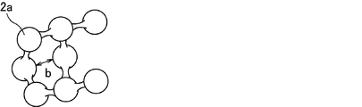
- FIG. 2 is a schematic diagram schematically illustrating the shape of a filtration layer formed from spherical ceramic particles having a large particle diameter
- FIG. 3 is a schematic diagram illustrating the shape of a filtration layer formed from spherical ceramic particles having a small particle diameter.
- FIG. 2 the pore diameter of the pores formed by the spherical ceramic particles 2A having a large particle diameter is indicated by a double arrow a.
- the pore diameter of the pores formed by the spherical ceramic particles 2a having a small particle diameter is indicated by a double arrow b.
- the pressure loss on the fluid outflow side is reduced by increasing the particle diameter of the spherical ceramic particles constituting the filtration layer on the fluid outflow side, which tends to increase the pressure loss due to the high exhaust gas velocity. Can do.
- the filtration layer on the fluid inflow side has a small pore diameter, it is suitable for collecting PM having a small particle diameter, and the collection efficiency on the fluid inflow side can be increased. Therefore, a filter with low pressure loss and high collection efficiency can be obtained.
- the honeycomb filter according to claim 2 at any one point in a region having a length of 7.5 to 12.5% from the end portion on the fluid inflow side with respect to the total length in the longitudinal direction of the ceramic honeycomb substrate.
- the average particle diameter of the spherical ceramic particles measured is 0.3 to 0.6 ⁇ m, and measured at an arbitrary point in the region having a length of 87.5 to 92.5% from the end on the fluid inflow side.
- the average particle size of the spherical ceramic particles is 0.6 to 2.5 ⁇ m.
- the average particle diameter of the spherical ceramic particles in the region of 7.5 to 12.5% from the end on the fluid inflow side is 0.3 to 0.6 ⁇ m
- PM having a small particle diameter is collected. Since a filtration layer having a particularly suitable pore diameter is formed, the collection efficiency on the fluid inflow side can be further increased.
- the average particle diameter of the spherical ceramic particles in the region having a length of 87.5 to 92.5% from the end portion on the fluid inflow side is 0.6 to 2.5 ⁇ m, the gas component of the exhaust gas passes through. Since a filtration layer having an easy pore diameter is formed, pressure loss on the fluid outflow side can be further reduced.
- honeycomb filter according to claim 3 wherein the spherical ceramic particles are heat-resistant oxide ceramic particles
- the honeycomb filter according to claim 4 wherein the heat-resistant oxide ceramic particles are alumina, silica, mullite, It is at least one selected from the group consisting of ceria, zirconia, cordierite, zeolite and titania.
- the filtration layer is a heat-resistant oxide, inconveniences such as melting of the filtration layer do not occur even when regeneration treatment for burning PM is performed. Therefore, a honeycomb filter having excellent heat resistance can be obtained.
- honeycomb filter according to claim 5 wherein the ceramic honeycomb substrate includes silicon carbide or silicon-containing silicon carbide. Silicon carbide and silicon-containing silicon carbide have high hardness and an extremely high thermal decomposition temperature. Therefore, the honeycomb filter is a honeycomb filter excellent in mechanical characteristics and heat resistance.
- FIG. 1 is a graph showing the relationship between the exhaust gas velocity and the location in the honeycomb filter cell.
- FIG. 2 is a schematic view schematically showing the shape of a filtration layer formed from spherical ceramic particles having a large particle diameter.
- FIG. 3 is a schematic view schematically showing the shape of a filtration layer formed from spherical ceramic particles having a small particle diameter.
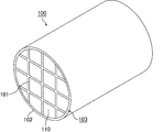
- FIG. 4 is a perspective view schematically showing an example of the honeycomb filter according to the first embodiment of the present invention.
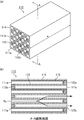
- Fig.5 (a) is a perspective view which shows typically an example of the honeycomb fired body which comprises the honeycomb filter shown in FIG.
- FIG. 5 (b) is a cross-sectional view taken along the line AA of the honeycomb fired body shown in FIG. 5 (a).
- FIG. 5 (a) is a perspective view schematically showing typically an example of the honeycomb fired body which comprises the honeycomb filter shown in FIG.
- FIG. 5 (b) is a cross-sectional view taken along the
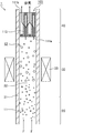
- FIG. 6 is an enlarged cross-sectional view schematically showing an example of a cell in which the end on the fluid inflow side is opened and the end on the fluid outflow side is sealed.
- FIG. 7A, FIG. 7B, and FIG. 7C are electron micrographs of the filtration layer.
- FIG. 8A, FIG. 8B, and FIG. 8C are diagrams showing particle size distribution curves of particles that constitute the filtration layer.
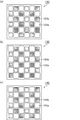
- FIGS. 9A, 9B and 9C are side views schematically showing an example of the cell structure of the honeycomb fired body constituting the honeycomb filter according to the first embodiment of the present invention.
- FIG. 10 is a cross-sectional view schematically showing an embodiment of a droplet dispersion step and a carrier gas inflow step.
- the ceramic honeycomb substrate (ceramic block) is composed of a plurality of honeycomb fired bodies.
- a large number of cells included in the honeycomb fired body constituting the honeycomb filter are composed of large-capacity cells and small-capacity cells, and the cross-sectional area perpendicular to the longitudinal direction of the large-capacity cells is perpendicular to the longitudinal direction of the small-capacity cells. Larger than the cross-sectional area.
- the honeycomb filter according to the first embodiment of the present invention is obtained by forming a filtration layer on the surface of a cell wall of a ceramic honeycomb substrate including a honeycomb fired body.
- ceramic honeycomb substrate those having a filtration layer formed on the surface of the cell wall
- honeycomb filter those having the filtration layer formed on the cell wall are referred to as “honeycomb filter”.
- cross section of the honeycomb fired body when the cross section of the honeycomb fired body is simply indicated, it indicates a cross section perpendicular to the longitudinal direction of the honeycomb fired body. Similarly, when simply expressed as the cross-sectional area of the honeycomb fired body, it refers to the area of the cross section perpendicular to the longitudinal direction of the honeycomb fired body.
- FIG. 4 is a perspective view schematically showing an example of the honeycomb filter according to the first embodiment of the present invention.
- Fig.5 (a) is a perspective view which shows typically an example of the honeycomb fired body which comprises the honeycomb filter shown in FIG.
- FIG. 5 (b) is a cross-sectional view taken along the line AA of the honeycomb fired body shown in FIG. 5 (a).
- honeycomb filter 100 a plurality of honeycomb fired bodies 110 are bound via an adhesive layer 101 to form a ceramic honeycomb substrate (ceramic block) 103, and this ceramic honeycomb substrate (ceramic block) ) On the outer periphery of 103, an outer peripheral coat layer 102 for preventing the leakage of exhaust gas is formed. In addition, the outer periphery coating layer should just be formed as needed.
- a honeycomb filter formed by binding a plurality of honeycomb fired bodies is also referred to as a collective honeycomb filter.
- the honeycomb fired body 110 constituting the honeycomb filter 100 will be described later, it is preferably a porous body made of silicon carbide or silicon-containing silicon carbide.
- a large number of cells 111a and 111b are arranged in the longitudinal direction (in the direction of arrow a in FIG. 5A) across the cell wall 113. And an outer peripheral wall 114 is formed on the outer periphery thereof. One end of the cells 111a and 111b is sealed with a sealing material 112a or 112b. And as shown in FIG.5 (b), the filtration layer 115 is formed in the surface of the cell wall 113 of the honeycomb fired body 110. FIG. In the honeycomb fired body 110 shown in FIG. 5A, the filtration layer 115 is not shown.
- a large-capacity cell 111a whose cross-sectional area perpendicular to the longitudinal direction is relatively larger than that of the small-capacity cell 111b, and a cross-section perpendicular to the longitudinal direction.
- small-capacity cells 111b whose area is relatively smaller than that of the large-capacity cell 111a.
- the shape of the cross section perpendicular to the longitudinal direction of the large capacity cell 111a is substantially octagonal, and the shape of the cross section perpendicular to the longitudinal direction of the small capacity cell 111b is substantially square.
- the large-capacity cell 111a has an opening on the first end face 117a side of the honeycomb fired body 110, and on the second end face 117b side. The end is sealed with a sealing material 112a.
- the small-capacity cell 111b the end portion on the second end face 117b side of the honeycomb fired body 110 is opened, and the end portion on the first end face 117a side is sealed with the sealing material 112b. Therefore, as shown in FIG. 5B, the exhaust gas G 1 flowing into the large-capacity cell 111a (in FIG.
- the exhaust gas is indicated by G 1 and the flow of the exhaust gas is indicated by an arrow) is always large.
- the small capacity cell 111b flows out.
- the exhaust gas G 1 is passing through the cell walls 113, since the PM and the like in the exhaust gas is collected, the cell wall 113 that separates the large-volume cells 111a and small-volume cell 111b functions as a filter.
- gas such as exhaust gas can be circulated through the large-capacity cells 111a and the small-capacity cells 111b of the honeycomb fired body 110.
- a gas such as exhaust gas is circulated in the direction shown in FIG.
- the end of the honeycomb fired body 110 on the first end face 117a side (the end on the side where the small capacity cells 111b are sealed) is fluidized.
- the end on the inflow side is referred to as the end on the second end face 117b side of the honeycomb fired body 110 (the end on the side where the large-capacity cells 111a are sealed) is referred to as the end on the fluid outflow side.
- the large capacity cell 111a having an open end on the fluid inflow side is a cell 111a on the fluid inflow side
- the small capacity cell 111b having an end on the fluid outflow side is a cell on the fluid outflow side. 111b.
- FIG. 6 is an enlarged cross-sectional view schematically showing an example of a cell in which the end on the fluid inflow side is opened and the end on the fluid outflow side is sealed.
- FIG. 6 schematically shows that the average particle diameter of the spherical ceramic particles gradually increases from the fluid inflow side to the fluid outflow side.
- the filtration layer 115 is also formed on the surface 112S of the sealing material exposed inside the cell.
- the spherical ceramic particles constituting the filtration layer 115 are indicated by white circles, and the particle diameter of the spherical ceramic particles is schematically indicated by the size of the circles.
- the spherical ceramic particles 116a constituting the filtration layer on the fluid inflow side are the smallest, and the spherical ceramic particles 116c constituting the filtration layer on the fluid outflow side are depicted largest.
- the particle diameter of the spherical ceramic particles 116b constituting the filtration layer in the central portion in the longitudinal direction of the honeycomb fired body is larger than the particle diameter of the spherical ceramic particles 116a and smaller than the particle diameter of the spherical ceramic particles 116c.
- FIG. 6 also schematically shows an example of a range for measuring the particle diameter of the spherical ceramic particles.
- the total length in the longitudinal direction of the honeycomb fired body is defined as 100%
- the position of the end portion on the fluid inflow side is defined as 0%
- the position of the end portion on the fluid outflow side is defined as 100%.
- 7.5% of position towards the end of the fluid outflow side from an end portion of the fluid inflow side and defines a 12.5% position
- the range between the two positions and W 1 Taken any electron micrograph at a point contained in the range W 1, the particle size of the measured spherical ceramic particles from the imaging results, the particle size of the spherical ceramic particles constituting the filtration layer in the fluid inflow side .
- the particle diameter of the spherical ceramic particles constituting the filtration layer in the central portion is larger than the average particle diameter of the spherical ceramic particles constituting the filtration layer on the fluid inflow side, and the filtration in the central portion.
- the particle diameter of the spherical ceramic particles constituting the layer is smaller than the average particle diameter of the spherical ceramic particles constituting the filtration layer on the fluid outflow side.
- the average particle diameter of the particles constituting the filtration layer can be measured by the following method.
- a honeycomb fired body included in each of the ranges W 1 , W 2 , and W 3 shown in FIG. 6 is processed to produce a 10 mm ⁇ 10 mm ⁇ 10 mm sample.
- the surface of the sample is observed with a scanning electron microscope (SEM) at any one of the prepared samples.
- SEM scanning electron microscope
- the particles constituting the filtration layer are set within one field of view.
- FE-SEM S-4800 manufactured by Hitachi is used as the SEM.
- the observation conditions of SEM are acceleration voltage: 15.00 kV, working distance (WD): 15.00 mm, and magnification: 10,000 times.
- the particle diameters of all the particles in one field of view are visually measured.
- the average value of the particle diameters of all particles measured within one field of view is defined as the average particle diameter.
- FIG. 7A, FIG. 7B, and FIG. 7C are electron micrographs of the filtration layer.
- Photograph shown in FIG. 7 (a) is a photograph of the filtration layer taken in the above range W 1
- photograph shown in FIG. 7 (b) is a photograph of the filtration layer taken in the range W 2
- 7 photograph shown in (c) is a photograph of the filtration layer taken in the range W 3.
- the spherical ceramic particles (116a, 116b, 116c) shown in these three photographs have the smallest particle diameters of the spherical ceramic particles 116a in FIG. 7 (a) and the spherical ceramic particles 116c in FIG. 7 (c). It is getting bigger.
- FIG. 8A, FIG. 8B, and FIG. 8C are diagrams showing particle size distribution curves of particles that constitute the filtration layer.
- the particle size distribution curves shown in FIG. 8 (a), FIG. 8 (b) and FIG. 8 (c) are from the electron micrographs shown in FIG. 7 (a), FIG. 7 (b) and FIG. 7 (c), respectively. It is the obtained particle size distribution curve.
- the average particle diameters of the spherical ceramic particles shown in FIGS. 8A, 8B, and 8C are 0.58 ⁇ m, 0.59 ⁇ m, and 0.70 ⁇ m, respectively. From this, it can be understood that the average particle diameter of the spherical ceramic particles constituting the filtration layer gradually increases from the fluid inflow side toward the fluid outflow side.
- the average particle diameter of the spherical ceramic particles constituting the filtration layer on the fluid inflow side is 0.3 to 0.6 ⁇ m, and the average of the spherical ceramic particles constituting the filtration layer on the fluid outflow side
- the particle size is preferably 0.6 to 2.5 ⁇ m.
- the spherical ceramic particles constituting the filtration layer are preferably heat-resistant oxide ceramic particles.
- the heat-resistant oxide ceramic particles include alumina, silica, mullite, ceria, zirconia, cordierite, zeolite, and titania. These may be used alone or in combination of two or more.
- alumina is preferred.
- the filtration layer is formed only on the surface of the cell wall of the cell in which the end on the fluid inflow side is opened and the end on the fluid outflow side is sealed. . Since the exhaust gas flows into the cell from the fluid inflow side of the honeycomb filter, a large amount of PM in the exhaust gas accumulates on the cell wall of the cell where the end on the fluid inflow side is opened and the end on the fluid outflow side is sealed. Is done. Therefore, if the filtration layer is formed only on the surface of the cell wall of the cell where the end on the fluid inflow side is opened and the end on the fluid outflow side is sealed, the PM deposited on the cell wall Depth filtration can be efficiently prevented.
- FIGS. 9A, 9B and 9C are side views schematically showing an example of the cell structure of the honeycomb fired body constituting the honeycomb filter according to the first embodiment of the present invention. .
- the filtration layer is not illustrated in FIGS. 9A, 9B, and 9C.
- the shape of the cross section perpendicular to the longitudinal direction of the large capacity cell 121a is substantially octagonal, and the shape of the cross section perpendicular to the longitudinal direction of the small capacity cell 121b is substantially rectangular.
- the large capacity cells 121a and the small capacity cells 121b are alternately arranged.
- the shape of the cross section perpendicular to the longitudinal direction of the large capacity cell 131a is substantially octagonal, and the shape of the cross section perpendicular to the longitudinal direction of the small capacity cell 131b.
- the honeycomb fired body 120 shown in FIG. 9 (a) and the honeycomb fired body 130 shown in FIG. 9 (b) have a cross section perpendicular to the longitudinal direction of the large capacity cell with respect to the area of the cross section perpendicular to the longitudinal direction of the small capacity cell.
- the area ratio of the areas is different. Further, in the honeycomb fired body 140 shown in FIG.
- the shape of the cross section perpendicular to the longitudinal direction of the large capacity cell 141a is substantially quadrangular, and the shape of the cross section perpendicular to the longitudinal direction of the small capacity cell 141b is approximately.
- the large-capacity cells 141a and the small-capacity cells 141b are alternately arranged.
- the area ratio of the area of the cross section perpendicular to the longitudinal direction of the large capacity cell to the area of the cross section perpendicular to the longitudinal direction of the small capacity cell is preferably 1.4 to 2.8, and more preferably 1.5 to 2.4.
- the filtration layer includes spherical ceramic particles, and the average particle diameter of the spherical ceramic particles is a method for manufacturing a honeycomb filter that gradually increases from the fluid inflow side toward the fluid outflow side,
- a ceramic honeycomb is used to produce a porous honeycomb fired body in which a large number of cells are arranged in parallel in the longitudinal direction across the cell wall, and either the fluid inflow side or the fluid outflow side of the cell is sealed
- Honeycomb fired body manufacturing process A droplet dispersion step of dispersing droplets containing the raw material of the spherical ceramic particles in a carrier gas; Drying the carrier gas at 100 to 800 ° C. to form spherical ceramic particles from droplets containing the raw material of the spherical ceramic particles; An inflow step of allowing the carrier gas to flow into a cell having an end on the fluid inflow side opened and a sealed end on the fluid outflow side, and depositing the spherical ceramic particles on the surface of the cell wall; And a heating step of heating the ceramic honeycomb substrate to 1100-1500 ° C.
- a ceramic honeycomb substrate including a honeycomb fired body is manufactured, and a filtration layer is formed on the surface of the cell wall of the ceramic honeycomb substrate.
- the procedure of the step of forming the filtration layer will be described.
- the filtration layer is formed on the surface of the cell wall of the ceramic honeycomb substrate by performing a droplet dispersion step, a drying step, a carrier gas inflow step, and a ceramic honeycomb substrate heating step.
- a case where the material constituting the filtration layer is a heat-resistant oxide will be described as an example.
- the process for producing the ceramic honeycomb substrate including the honeycomb fired body will be described later.
- FIG. 10 is a cross-sectional view schematically showing an embodiment of a droplet dispersion step and a carrier gas inflow step.
- FIG. 10 shows a carrier gas inflow apparatus 1 which is an apparatus for causing a carrier gas to flow into the cells of the ceramic honeycomb substrate.
- the carrier gas inflow device 1 includes a droplet dispersion unit 20 that disperses droplets in the carrier gas, a piping unit 30 through which the carrier gas in which the droplets are dispersed passes, and an inflow unit that flows the carrier gas into the cells of the ceramic honeycomb substrate. 40.
- the droplet dispersion step and the carrier gas inflow step are performed using the carrier gas inflow device 1 will be described.
- the carrier gas F flows from the lower side to the upper side in FIG.
- the carrier gas F is introduced from below the carrier gas inflow device 1, and is discharged from above the inflow portion 40 through the droplet dispersion portion 20, the piping portion 30, and the inflow portion 40.
- the carrier gas F is pressurized from the lower side to the upper side in FIG. 10 by the pressure difference generated by the pressurization from the lower side of the carrier gas inflow device or the suction from the upper side of the carrier gas inflow device. Flows upward in 1.
- a gas that does not react by heating up to 800 ° C. and does not react with the components in the droplets dispersed in the carrier gas is used.
- the carrier gas include gases such as air, nitrogen, and argon.
- an oxide-containing solution filled in a tank (not shown) is formed into droplets 11 by spraying and dispersed in the carrier gas F.
- the oxide-containing solution is a concept including a solution containing a heat-resistant oxide precursor in which a heat-resistant oxide is formed by heating, or a slurry containing heat-resistant oxide particles.
- the heat-resistant oxide precursor means a compound derived from a heat-resistant oxide by heating. Examples thereof include metal hydroxides, carbonates, nitrates, and hydrates constituting the heat-resistant oxide.
- the slurry containing heat-resistant oxide particles is a solution in which heat-resistant oxide particles are suspended in water.
- the droplets 11 dispersed in the carrier gas F ride on the carrier gas F and flow above the carrier gas inflow device 1 and pass through the piping part 30.
- the pipe part 30 of the carrier gas inflow device 1 is a pipe through which the carrier gas F in which the droplets 11 are dispersed passes.
- the passage 32 through which the carrier gas F passes in the pipe portion 30 is a space surrounded by the pipe wall 31 of the pipe.
- a heating mechanism 33 is provided in the piping part 30.
- An example of the heating mechanism 33 is an electric heater.
- the pipe wall 31 is heated using the heating mechanism 33, and the carrier gas F in which the droplets 11 are dispersed is allowed to pass through. And the carrier gas F which passes the piping part 30 is heated, and the droplet 11 disperse
- the droplet 11 is heated, the liquid component contained in the droplet evaporates to form spherical ceramic particles 12.
- the spherical ceramic particles 12 are indicated by white circles.
- the heat-resistant oxide precursor is contained in the droplet, the heat-resistant oxide precursor becomes a heat-resistant oxide (spherical ceramic particles) by heating the carrier gas.
- the pipe wall 31 is heated to 100 to 800 ° C. using the heating mechanism 33 and the carrier gas F in which the droplets 11 are dispersed is allowed to pass for 0.1 to 3.0 seconds. If the temperature of the heated pipe is less than 100 ° C. and the time for passing the carrier gas through the pipe is less than 0.1 seconds, the water in the droplets may not be sufficiently evaporated. On the other hand, if the temperature of the heated pipe exceeds 800 ° C. and the time for passing the carrier gas through the pipe exceeds 3.0 seconds, the energy required for manufacturing the honeycomb filter becomes too large. The manufacturing efficiency of the honeycomb filter is reduced.
- the length of the pipe is not particularly limited, but is preferably 500 to 3000 mm. If the length of the pipe is less than 500 mm, the moisture in the droplets may not be sufficiently evaporated even if the speed at which the carrier gas passes through the pipe is slowed. On the other hand, if the length of the pipe exceeds 3000 mm, the apparatus for manufacturing the honeycomb filter becomes too large, and the manufacturing efficiency of the honeycomb filter is lowered.
- the spherical ceramic particles 12 ride on the flow of the carrier gas F and flow above the carrier gas inflow device 1, and flow into the cells of the ceramic honeycomb substrate 103 at the inflow portion 40.
- a ceramic block in which a plurality of honeycomb fired bodies are bound through an adhesive layer is used as the ceramic honeycomb substrate.
- the ceramic honeycomb substrate 103 is arranged at the upper part of the carrier gas inflow device 1 so as to close the outlet of the carrier gas inflow device 1. Therefore, the carrier gas F always flows into the ceramic honeycomb substrate 103.
- FIG. 10 schematically shows a cross section of the honeycomb fired body constituting the ceramic block (a cross section similar to that shown in FIG. 5B) as a cross section of the ceramic honeycomb substrate 103.
- the end of the cell 111a on the fluid inflow side is open, and the cell 111b on the fluid outflow side is plugged. Therefore, the carrier gas F flows into the ceramic honeycomb substrate 103 from the opening of the cell 111a on the fluid inflow side.
- the carrier gas F in which the spherical ceramic particles 12 are dispersed flows into the cell 111 a on the fluid inflow side of the ceramic honeycomb substrate 103, the spherical ceramic particles 12 are deposited on the surface of the cell wall 113 of the ceramic honeycomb substrate 103.
- the ceramic honeycomb substrate 103 is heated to 100 to 800 ° C. and the carrier gas F is allowed to flow into the heated cell.
- the ceramic honeycomb substrate 103 is heated to 100 to 800 ° C., even if the liquid component remains in the spherical ceramic particles 12, the liquid component evaporates, and the surface of the cell wall is in a dry powder state. To deposit.
- the carrier gas F flows into the inside of the ceramic honeycomb substrate 103 from the opening of the cell 111a on the fluid inflow side, passes through the cell wall 113 of the ceramic honeycomb substrate 103, and flows out from the opening of the cell 111b on the fluid outflow side.
- the carrier gas inflow process is performed by such a procedure.
- the spherical ceramic particles formed in the drying process are a mixture of a plurality of spherical ceramic particles having different particle sizes.
- particles having a large particle diameter are likely to accumulate on the cell wall on the fluid outflow side (near the sealing material) on the carrier gas flow.
- particles having a small particle diameter are likely to accumulate on the cell wall on the fluid inflow side. Therefore, the average particle diameter of the spherical ceramic particles gradually increases from the fluid inflow side toward the fluid outflow side.
- the ceramic honeycomb substrate on which the spherical ceramic particles adhere to the cell walls through the carrier gas inflow step is heated at a furnace temperature of 1100 to 1500 ° C. using a heating furnace.
- the heating atmosphere is preferably an air atmosphere, a nitrogen atmosphere, or an argon atmosphere.
- a part of the spherical ceramic particles is sintered and becomes a crosslinked body to bond the spherical ceramic particles.
- the spherical ceramic particles adhering to the surface of the cell wall are thermally contracted by heating and firmly adhered to the surface of the cell wall.
- a filtration layer is formed through the above steps.
- the ceramic honeycomb substrate produced below is a ceramic block in which a plurality of honeycomb fired bodies are bundled through an adhesive layer.
- silicon carbide used as the ceramic powder.
- a forming step for producing a honeycomb formed body by extruding a wet mixture containing a ceramic powder and a binder is performed. Specifically, first, a wet mixture for manufacturing a honeycomb formed body is prepared by mixing silicon carbide powder having different average particle sizes as ceramic powder, an organic binder, a liquid plasticizer, a lubricant, and water. To prepare.
- a honeycomb formed body having a predetermined shape.
- a honeycomb formed body is manufactured using a mold that has a cross-sectional shape having a cell structure (cell shape and cell arrangement) shown in FIGS. 5 (a) and 5 (b).
- the honeycomb formed body is cut to a predetermined length, dried using a microwave dryer, hot air dryer, dielectric dryer, vacuum dryer, vacuum dryer, freeze dryer, etc.
- a sealing step of filling the cell with a sealing material paste as a sealing material and sealing the cell is performed.
- the wet mixture can be used as the sealing material paste.
- the degreased honeycomb formed body is conveyed to a firing furnace, and the firing step is performed.
- a honeycomb fired body as shown in FIGS. 5A and 5B is manufactured.
- the sealing material paste with which the edge part of the cell was filled is baked by heating and becomes a sealing material.
- the conditions currently used when manufacturing a honeycomb fired body can be applied to the conditions of a cutting process, a drying process, a sealing process, a degreasing process, and a firing process.
- a bundling process is performed in which a plurality of honeycomb fired bodies are sequentially stacked and bonded via an adhesive paste on a support stand to produce a honeycomb aggregate in which a plurality of honeycomb fired bodies are stacked.
- the adhesive paste for example, a paste made of an inorganic binder, an organic binder, and inorganic particles is used.
- the adhesive paste may further contain inorganic fibers and / or whiskers.
- honeycomb aggregate is heated and the adhesive paste is heated and solidified to form an adhesive layer, thereby producing a quadrangular columnar ceramic block.
- the conditions for heating and solidifying the adhesive paste the conditions conventionally used when producing a honeycomb filter can be applied.
- a cutting process for cutting the ceramic block is performed. Specifically, a ceramic block whose outer periphery is processed into a substantially cylindrical shape is manufactured by cutting the outer periphery of the ceramic block using a diamond cutter.
- An outer peripheral coating layer forming step is performed in which an outer peripheral coating material paste is applied to the outer peripheral surface of the substantially cylindrical ceramic block, and dried and solidified to form an outer peripheral coating layer.
- the said adhesive paste can be used as an outer periphery coating material paste.
- the outer peripheral coat layer is not necessarily provided, and may be provided as necessary.
- a filter layer is formed on the surface of the cell wall of the ceramic honeycomb substrate. It can be formed to produce a honeycomb filter.
- the filtration layer is formed on the surface of the cell wall of the cell in which the end on the fluid inflow side is opened and the end on the fluid outflow side is sealed. Therefore, PM depth filtration can be efficiently prevented.
- the average particle diameter of the spherical ceramic particles constituting the filtration layer is gradually increased from the fluid inflow side to the fluid outflow side. That is, spherical ceramic particles having a small particle diameter exist on the fluid inflow side, and spherical ceramic particles having a large particle diameter exist on the fluid outflow side. Increasing the pore size of the filtration layer on the fluid outflow side by increasing the particle size of the spherical ceramic particles that constitute the filtration layer on the fluid outflow side, which tends to increase the pressure loss due to the high exhaust gas velocity And pressure loss on the fluid outflow side can be reduced.
- the filtration layer on the fluid inflow side is suitable for collecting PM having a small particle size because the particle diameter of the spherical ceramic particles is small and the pore size of the filtration layer is small. Efficiency can be increased. Therefore, a filter with low pressure loss and high collection efficiency can be obtained.
- the average particle diameter of the spherical ceramic particles measured is 0.3 to 0.6 ⁇ m, and measured at an arbitrary point in the region having a length of 87.5 to 92.5% from the end on the fluid inflow side.
- the average particle size of the spherical ceramic particles is 0.6 to 2.5 ⁇ m.
- a filtration layer having a pore size suitable for the above Since a filtration layer having a pore size suitable for the above is formed, the collection efficiency on the fluid inflow side can be further increased. Further, when the average particle diameter of the spherical ceramic particles in the region having a length of 87.5 to 92.5% from the end portion on the fluid inflow side is 0.6 to 2.5 ⁇ m, the gas component of the exhaust gas passes through. Since a filtration layer having an easy pore diameter is formed, pressure loss on the fluid outflow side can be further reduced.
- the spherical ceramic particles are heat-resistant oxide ceramic particles, and the heat-resistant oxide ceramic particles are from alumina, silica, mullite, ceria, zirconia, cordierite, zeolite, and titania. Is at least one selected from the group consisting of When the filtration layer is made of heat-resistant oxide ceramic particles, inconveniences such as melting of the filtration layer do not occur even when regeneration treatment for burning PM is performed. Therefore, a honeycomb filter having excellent heat resistance can be obtained.
- the ceramic honeycomb substrate includes silicon carbide or silicon-containing silicon carbide. Silicon carbide and silicon-containing silicon carbide have high hardness and an extremely high thermal decomposition temperature. Therefore, the honeycomb filter is a honeycomb filter excellent in mechanical characteristics and heat resistance.
- Example 1 (Production of ceramic honeycomb substrate) First, 54.6% by weight of a coarse powder of silicon carbide having an average particle diameter of 22 ⁇ m and 23.4% by weight of a fine powder of silicon carbide having an average particle diameter of 0.5 ⁇ m were mixed. An organic binder (methylcellulose) 4.3 wt%, a lubricant (Unilube made by NOF Corporation) 2.6 wt%, glycerin 1.2 wt%, and water 13.9 wt% are added and kneaded to obtain a wet mixture. After being obtained, a molding step of extrusion molding was performed. In this step, a raw honeycomb molded body having the same shape as the honeycomb fired body 110 shown in FIG. 5A and having no cell plugged was produced.
- a lubricant Unilube made by NOF Corporation
- the raw honeycomb formed body was dried using a microwave dryer, thereby manufacturing a dried body of the honeycomb formed body.
- the sealing material paste was filled in predetermined cells of the dried honeycomb molded body to seal the cells.
- the wet mixture was used as a sealing material paste.
- the dried honeycomb molded body filled with the plug paste was again dried using a dryer.
- honeycomb fired bodies By applying an adhesive paste between the honeycomb fired bodies obtained by the above process to form an adhesive paste layer, and heating and solidifying the adhesive paste layer to form an adhesive layer, 16 honeycomb fired bodies are obtained. A substantially prismatic ceramic block formed by binding through an adhesive layer was produced.
- As the adhesive paste 30% by weight of alumina fibers having an average fiber length of 20 ⁇ m, 21% by weight of silicon carbide particles having an average particle diameter of 0.6 ⁇ m, 15% by weight of silica sol, 5.6% by weight of carboxymethylcellulose, and water 28 An adhesive paste containing 4% by weight was used.
- a cylindrical ceramic block having a diameter of 142 mm was prepared by cutting the outer periphery of the prismatic ceramic block using a diamond cutter.
- the outer peripheral coating material paste was applied to the outer peripheral surface of the columnar ceramic block, and the outer peripheral coating material paste was heated and solidified at 120 ° C. to form an outer peripheral coating layer on the outer peripheral portion of the ceramic block.
- the paste similar to the said adhesive material paste was used as the said outer periphery coating material paste.
- a filter layer was formed on the ceramic honeycomb substrate using the carrier gas inflow device shown in FIG. As shown in FIG. 10, a ceramic honeycomb substrate was disposed above the carrier gas inflow device. At this time, the ceramic honeycomb substrate was disposed with the opening of a large-capacity cell as a cell on the fluid inflow side facing downward of the carrier gas inflow device.
- a solution containing boehmite which is a heat-resistant oxide precursor was prepared.
- the concentration of boehmite was 3.8 mol / l.
- the droplets containing boehmite were dispersed in the carrier gas by spraying.
- the temperature of the wall of the pipe of the carrier gas inflow device is heated to 200 ° C., and the carrier gas is flowed toward the upper side (ceramic honeycomb substrate side) of the carrier gas inflow device at a flow rate of 15.8 mm / sec.
- the water in the droplets dispersed therein was evaporated.
- the length of the pipe was 1200 mm.
- the carrier gas in which the spherical alumina particles were dispersed was allowed to flow into the cells of the ceramic honeycomb substrate, and the spherical alumina particles were adhered to the surface of the cell walls.
- the ceramic honeycomb substrate was taken out from the carrier gas inflow device and heated in a firing furnace at 1350 ° C. for 3 hours in an air atmosphere.
- a honeycomb filter in which a filtration layer made of alumina particles was formed on the surface of the cell wall was manufactured.
- Photographs of the filter layer of the honeycomb filter obtained by the above process are photographs shown in FIGS. 7 (a), 7 (b), and 7 (c).
- the photographing conditions for the SEM photograph are: device name: manufactured by Hitachi, FE-SEM S-4800, backscattered electron image, acceleration voltage 15.0 kV, and magnification 10000 times.
- a particle size distribution curve was obtained from photographs taken in the range W 1 , range W 2 , and range W 3 shown in FIG. 6, and the average particle size of the spherical ceramic particles was measured by the measurement method described above.
- the average particle diameter of the spherical ceramic particles is 0.58 ⁇ m, 0.59 ⁇ m, and 0.70 ⁇ m, respectively.
- the average particle diameter of the spherical ceramic particles constituting the filtration layer is from the fluid inflow side to the fluid outflow side. It is getting bigger gradually.
- the average particle diameter of the spherical ceramic particles in the region having a length of 7.5 to 12.5% from the end portion on the fluid inflow side is in the range of 0.3 to 0.6 ⁇ m. Since a filtration layer having a pore size suitable for collecting PM having a small particle diameter is formed, the collection efficiency on the fluid inflow side is increased.
- the average particle diameter of the spherical ceramic particles in the region having a length of 87.5 to 92.5% from the end on the fluid inflow side is in the range of 0.6 to 2.5 ⁇ m. Therefore, a filtration layer having a pore diameter through which the gas component of the exhaust gas easily passes is formed, so that the pressure loss on the fluid outflow side is reduced.
- the filtration layer is formed only on the surface of the cell wall of the cell in which the end portion on the fluid inflow side is opened and the end portion on the fluid outflow side is sealed.
- the filtration layer has an opening at the end on the fluid inflow side and a surface of the cell wall of the cell where the end on the fluid outflow side is sealed, The end portion on the fluid inflow side may be sealed, and the end portion on the fluid outflow side may be formed on the surface of the cell wall of the cell.
- Such a honeycomb filter can be manufactured by immersing the ceramic honeycomb substrate in a slurry containing spherical ceramic particles prepared in advance and then heating.
- the droplets may contain heat-resistant oxide particles as a raw material for the ceramic particles.
- the moisture in the droplets can be removed by heating the carrier gas to obtain heat-resistant oxide particles.
- grains of a heat resistant oxide can be formed by flowing the particle
- the filtration layer comprised of the particles of the heat-resistant oxide can also be formed by removing the moisture in the droplets after flowing the droplet containing the heat-resistant oxide particles into the cell.
- the shape of the cross section perpendicular to the longitudinal direction of the cells of the honeycomb fired body constituting the honeycomb filter may be all equal, or at one end face of the honeycomb fired body.
- the cross-sectional areas perpendicular to the longitudinal direction of the sealed cell and the opened cell may be equal to each other.
- the ceramic honeycomb substrate may be composed of one honeycomb fired body.
- a honeycomb filter made of one honeycomb fired body is also referred to as an integral honeycomb filter.
- cordierite or aluminum titanate can be used as the main constituent material of the integral honeycomb filter.
- the shape of the cross section perpendicular to the longitudinal direction of the honeycomb fired body of each cell of the honeycomb fired body is not limited to a substantially square shape, for example, a substantially circular shape or a substantially elliptical shape. Any shape such as a substantially pentagon, a substantially hexagon, a substantially trapezoid, or a substantially octagon may be used. Various shapes may be mixed.
- a filtration layer is formed on the surface of the cell wall of the ceramic honeycomb substrate, the filtration layer includes spherical ceramic particles, and the average particle size of the spherical ceramic particles is determined from the fluid inflow side to the fluid outflow. Increasing gradually toward the side is an essential component.
- the essential components include various configurations described in detail in the first embodiment and the other embodiments (for example, the configuration of the filtration layer, the method of forming the filtration layer, the cell structure of the honeycomb fired body, the manufacture of the honeycomb filter) Desired effects can be obtained by appropriately combining the steps and the like.
Landscapes
- Chemical & Material Sciences (AREA)
- Engineering & Computer Science (AREA)
- Ceramic Engineering (AREA)
- Materials Engineering (AREA)
- Structural Engineering (AREA)
- Organic Chemistry (AREA)
- Inorganic Chemistry (AREA)
- Mechanical Engineering (AREA)
- Combustion & Propulsion (AREA)
- General Engineering & Computer Science (AREA)
- Filtering Materials (AREA)
- Physics & Mathematics (AREA)
- Geometry (AREA)
- Chemical Kinetics & Catalysis (AREA)
- Manufacturing & Machinery (AREA)
- Processes For Solid Components From Exhaust (AREA)
- Filtering Of Dispersed Particles In Gases (AREA)
- Porous Artificial Stone Or Porous Ceramic Products (AREA)
- Civil Engineering (AREA)
Description
このような排ガス浄化装置は、セラミック等の材料からなるハニカムフィルタを用いて作製される。ハニカムフィルタ内に排ガスを通過させることによって排ガスを浄化することができる。
コンポジット領域を形成するために堆積される粒子の平均粒子径は1~15μmと規定されており、実施例としては平均粒子径が3μmであるコージェライト粒子を固気二相流により供給する例が示されている。
上記実施例で作製されるハニカムフィルタにおいては、平均粒子径が3μmである粒子がセル壁の表層全体にわたって均一に堆積しているものと考えられる。
上記セル壁の表面のうち、上記流体流入側の端部が開口され、上記流体流出側の端部が封止材により封止されたセルのセル壁の表面に形成された濾過層とを備えたハニカムフィルタであって、
上記濾過層は球状セラミック粒子を含み、上記球状セラミック粒子の平均粒子径は、上記流体流入側から上記流体流出側に向かって漸次大きくなることを特徴とする。
図1は、排ガスの速度とハニカムフィルタのセル内の場所の関係を示すグラフである。
横軸は、流体流入側の端部を0、流体流出側の端部を1.0とした相対位置を示しており、縦軸は、相対速度を示している。
このグラフからは、排ガスの速度は、流体流出側の端部で急激に大きくなる。
そして、流体流出側の端部では、排ガスの速度が大きいため圧力損失が高くなる。
すなわち、流体流入側には粒子径の小さい球状セラミック粒子が存在し、流体流出側には粒子径の大きい球状セラミック粒子が存在している。
図2には、粒子径の大きい球状セラミック粒子2Aによって形成される気孔の気孔径を両矢印aで示している。
一方、図3には、粒子径の小さい球状セラミック粒子2aによって形成される気孔の気孔径を両矢印bで示している。
この2つの図から、粒子径の大きい球状セラミック粒子によって構成される濾過層の気孔径は大きくなり、粒子径の小さい球状セラミック粒子によって構成される濾過層の気孔径は小さくなることが理解される。
そのため、圧力損失が低く、捕集効率の高いフィルタとすることができる。
濾過層が耐熱性酸化物であると、PMを燃焼させる再生処理を行った際にも、濾過層が溶融する等の不都合が発生しない。そのため、耐熱性に優れたハニカムフィルタとすることができる。
炭化ケイ素及びケイ素含有炭化ケイ素は、高い硬度を有し、熱分解温度が極めて高い。そのため、上記ハニカムフィルタは、機械的特性及び耐熱性に優れたハニカムフィルタとなる。
以下、本発明のハニカムフィルタ、及び、ハニカムフィルタの製造方法の一実施形態である第一実施形態について説明する。
本明細書においては、セル壁の表面に濾過層が形成されていないものを「セラミックハニカム基材」、セル壁の表面に濾過層が形成されたものを「ハニカムフィルタ」として両者を区別する。
また、以下の説明において、単に、ハニカム焼成体の断面と表記した場合、ハニカム焼成体の長手方向に垂直な断面を指す。同様に、単に、ハニカム焼成体の断面積と表記した場合、ハニカム焼成体の長手方向に垂直な断面の面積を指す。
図5(a)は、図4に示すハニカムフィルタを構成するハニカム焼成体の一例を模式的に示す斜視図である。図5(b)は、図5(a)に示すハニカム焼成体のA-A線断面図である。
このような、複数個のハニカム焼成体が結束されてなるハニカムフィルタは、集合型ハニカムフィルタともいう。
ハニカムフィルタ100を構成するハニカム焼成体110については後述するが、炭化ケイ素又はケイ素含有炭化ケイ素からなる多孔質体であることが好ましい。
そして、図5(b)に示すように、ハニカム焼成体110のセル壁113の表面には、濾過層115が形成されている。なお、図5(a)に示すハニカム焼成体110では、濾過層115を図示していない。
大容量セル111aの長手方向に垂直な断面の形状は略八角形であり、小容量セル111bの長手方向に垂直な断面の形状は略四角形である。
従って、図5(b)に示すように、大容量セル111aに流入した排ガスG1(図5(b)中、排ガスをG1で示し、排ガスの流れを矢印で示す)は、必ず、大容量セル111aと小容量セル111bとを隔てるセル壁113を通過した後、小容量セル111bから流出するようになっている。排ガスG1がセル壁113を通過する際に、排ガス中のPM等が捕集されるため、大容量セル111a及び小容量セル111bを隔てるセル壁113は、フィルタとして機能する。
このように、ハニカム焼成体110の大容量セル111a及び小容量セル111bには、排ガス等の気体を流通させることができる。図5(b)に示す方向に排ガス等の気体を流通させる場合、ハニカム焼成体110の第1の端面117a側の端部(小容量セル111bが封止されている側の端部)を流体流入側の端部といい、ハニカム焼成体110の第2の端面117b側の端部(大容量セル111aが封止されている側の端部)を流体流出側の端部という。
図6は、流体流入側の端部が開口され、流体流出側の端部が封止されたセルの一例を拡大して模式的に示した拡大断面図である。
図6には、球状セラミック粒子の平均粒子径が、流体流入側から流体流出側に向かって漸次大きくなっていることを模式的に示している。
また、濾過層115は、セル内部に露出する封止材の表面112Sにも形成されている。
図6では、流体流入側における濾過層を構成する球状セラミック粒子116aが最も小さく、流体流出側における濾過層を構成する球状セラミック粒子116cが最も大きく描かれている。
また、ハニカム焼成体の長手方向の中央部における濾過層を構成する球状セラミック粒子116bの粒子径が、球状セラミック粒子116aの粒子径より大きく、球状セラミック粒子116cの粒子径よりも小さくなっている。
ハニカム焼成体の長手方向における全長を100%とし、流体流入側の端部の位置を0%、流体流出側の端部の位置を100%と定める。
そして、流体流入側の端部から流体流出側の端部に向かって7.5%の位置、及び、12.5%の位置を定め、この2つの位置の間の範囲をW1とする。
上記範囲W1の中に含まれる任意の一点で電子顕微鏡写真を撮影し、撮影結果から測定した球状セラミック粒子の粒子径が、流体流入側における濾過層を構成する球状セラミック粒子の粒子径となる。
同様に、流体流入側の端部から流体流出側の端部に向かって47.5%の位置、及び、52.5%の位置を定め、この2つの位置の間の範囲をW2とする。
上記範囲W2の中に含まれる任意の一点で電子顕微鏡写真を撮影し、撮影結果から測定した球状セラミック粒子の粒子径が、中央部における濾過層を構成する球状セラミック粒子の粒子径となる。
同様に、流体流入側の端部から流体流出側の端部に向かって87.5%の位置、及び、92.5%の位置を定め、この2つの位置の間の範囲をW3とする。
上記範囲W3の中に含まれる任意の一点で電子顕微鏡写真を撮影し、撮影結果から測定した球状セラミック粒子の粒子径が、流体流出側における濾過層を構成する球状セラミック粒子の粒子径となる。
このような関係が満たされているとき、濾過層を構成する球状セラミック粒子の平均粒子径が、流体流入側から流体流出側に向かって漸次大きくなっているといえる。
まず、図6で示す範囲W1、W2、W3の中にそれぞれ含まれるハニカム焼成体を加工して、10mm×10mm×10mmのサンプルを作製する。
作製した各サンプルの任意の1箇所について、サンプルの表面を走査型電子顕微鏡(SEM)で観察する。この際、濾過層を構成する粒子が一視野内に入るようにする。ここで、SEMとしては、Hitachi製、FE-SEM S-4800を使用する。また、SEMの観察条件は、加速電圧:15.00kV、作動距離(WD):15.00mm、倍率:10000倍とする。
次に、一視野内における全ての粒子の粒子径を目視で測定する。一視野内にて測定した全ての粒子の粒子径の平均値を平均粒子径とする。
図7(a)に示す写真は、上記範囲W1で撮影した濾過層の写真であり、図7(b)に示す写真は、上記範囲W2で撮影した濾過層の写真であり、図7(c)に示す写真は、上記範囲W3で撮影した濾過層の写真である。
この3枚の写真に写っている球状セラミック粒子(116a、116b、116c)の粒子径は、図7(a)における球状セラミック粒子116aが最も小さく、図7(c)における球状セラミック粒子116cが最も大きくなっている。図7(b)における球状セラミック粒子116bの大きさは球状セラミック粒子116aと球状セラミック粒子116cの大きさの中間である。
この写真からも、濾過層を構成する球状セラミック粒子の平均粒子径が、流体流入側から流体流出側に向かって漸次大きくなっていることが理解できる。
図8(a)、図8(b)及び図8(c)は、濾過層を構成する粒子の粒子径分布曲線を示す図面である。図8(a)、図8(b)及び図8(c)に示す粒子径分布曲線は、それぞれ、図7(a)、図7(b)及び図7(c)に示す電子顕微鏡写真から得られた粒子径分布曲線である。
図8(a)、図8(b)及び図8(c)に示す球状セラミック粒子の平均粒子径はそれぞれ0.58μm、0.59μm、0.70μmとなっている。
このことから、濾過層を構成する球状セラミック粒子の平均粒子径が、流体流入側から流体流出側に向かって漸次大きくなっていることが理解できる。
耐熱性酸化物セラミック粒子としては、アルミナ、シリカ、ムライト、セリア、ジルコニア、コージェライト、ゼオライト及びチタニア等が挙げられる。これらは単独で用いてもよく、2種以上を併用してもよい。
上記耐熱性酸化物セラミック粒子の中では、アルミナが好ましい。
排ガスはハニカムフィルタの流体流入側からセル内に流入するため、排ガス中のPMは、流体流入側の端部が開口され、流体流出側の端部が封止されたセルのセル壁に多く堆積される。従って、濾過層が、流体流入側の端部が開口され、流体流出側の端部が封止されたセルのセル壁の表面のみに形成されていると、上記セル壁に堆積されたPMの深層濾過を効率良く防止することができる。
図9(a)、図9(b)及び図9(c)は、本発明の第一実施形態に係るハニカムフィルタを構成するハニカム焼成体のセル構造の一例を模式的に示す側面図である。
なお、図9(a)、図9(b)及び図9(c)では、濾過層を図示していない。
また、図9(c)に示すハニカム焼成体140においては、大容量セル141aの長手方向に垂直な断面の形状は略四角形であり、小容量セル141bの長手方向に垂直な断面の形状は略四角形であり、大容量セル141aと小容量セル141bとが交互に配列されている。
流体流入側のセルを大容量セルとし、流体流出側のセルを小容量セルとすることにより、流体流入側のセル(大容量セル)に多くのPMを堆積させることができるが、上記面積比が1.4未満であると、大容量セルの断面積と小容量セルの断面積との差が小さいため、大容量セル及び小容量セルを設けた効果が得られにくくなる。一方、上記面積比が2.8を超えると、小容量セルの長手方向に垂直な断面の面積が小さくなりすぎるため、排ガス等の気体が流体流出側のセル(小容量セル)を通過する際の摩擦に起因する圧力損失が大きくなる。
本発明の第一実施形態に係るハニカムフィルタの製造方法は、
流体を流通させるための多数のセルがセル壁を隔てて長手方向に並設され、上記セルの流体流入側又は流体流出側のいずれかの端部が封止されてなるセラミックハニカム基材と、
上記セル壁の表面のうち、上記流体流入側の端部が開口され、上記流体流出側の端部が封止されたセルのセル壁の表面に形成された濾過層とを備え、
上記濾過層は球状セラミック粒子を含み、上記球状セラミック粒子の平均粒子径は、上記流体流入側から上記流体流出側に向かって漸次大きくなるハニカムフィルタの製造方法であって、
セラミック粉末を用いて多数のセルがセル壁を隔てて長手方向に並設され、上記セルの流体流入側又は流体流出側のいずれかの端部が封止された多孔質のハニカム焼成体を製造するハニカム焼成体製造工程と、
上記球状セラミック粒子の原材料を含む液滴をキャリアガス中に分散させる液滴分散工程と、
上記キャリアガスを100~800℃で乾燥し、上記球状セラミック粒子の原材料を含む液滴から球状セラミック粒子を形成する乾燥工程と、
上記キャリアガスを、流体流入側の端部が開口され、流体流出側の端部が封止されたセルに流入させ、上記球状セラミック粒子を上記セル壁の表面に堆積させる流入工程と、
上記セラミックハニカム基材を1100~1500℃に加熱する加熱工程とを含むことを特徴とする。
以下、他の工程の説明に先立ち、濾過層を形成する工程の手順について説明する。
本実施形態では、液滴分散工程、乾燥工程、キャリアガスの流入工程、及び、セラミックハニカム基材の加熱工程を行うことによって、セラミックハニカム基材のセル壁の表面に濾過層を形成する。
また、本実施形態の説明では、濾過層を構成する材料が耐熱性酸化物である場合を例にして説明する。
なお、ハニカム焼成体を含むセラミックハニカム基材を作製する工程については後述する。
図10には、キャリアガスをセラミックハニカム基材のセルに流入させる装置である、キャリアガス流入装置1を示している。
キャリアガス流入装置1は、キャリアガス中に液滴を分散させる液滴分散部20、液滴が分散したキャリアガスが通過する配管部30、キャリアガスをセラミックハニカム基材のセルに流入させる流入部40を備える。
以下、キャリアガス流入装置1を用いて液滴分散工程及びキャリアガスの流入工程を行う場合の例を説明する。
キャリアガスとしては、800℃までの加熱で反応せず、また、キャリアガス中に分散する液滴中の成分と反応しないガスが用いられる。
キャリアガスの例としては、空気、窒素、アルゴン等のガスが挙げられる。
酸化物含有溶液とは、加熱により耐熱性酸化物が形成される耐熱性酸化物前駆体を含む溶液、又は、耐熱性酸化物粒子を含むスラリーを含む概念である。
例えば、耐熱性酸化物を構成する金属の水酸化物、炭酸塩、硝酸塩、水和物などが挙げられる。
耐熱性酸化物がアルミナの場合の耐熱性酸化物前駆体、すなわちアルミナ前駆体としては硝酸アルミニウム、水酸化アルミニウム、ベーマイト、ダイアスポアなどが挙げられる。
配管部30の、キャリアガスFが通過する通路32は、配管の管壁31で囲まれた空間である。
加熱機構33としては、電気ヒーター等が挙げられる。
液滴11が加熱されると、液滴に含まれる液体成分が蒸発し、球状セラミック粒子12が形成される。
図10では、球状セラミック粒子12を、白い丸で示している。
液滴に耐熱性酸化物前駆体が含まれている場合、キャリアガスの加熱により耐熱性酸化物前駆体は耐熱性酸化物(球状セラミック粒子)となる。
加熱された配管の温度が100℃未満であり、かつ、キャリアガスを配管に通過させる時間が0.1秒間未満であると、液滴中の水分を充分に蒸発させることができないことがある。
一方、加熱された配管の温度が800℃を超え、かつ、キャリアガスを配管に通過させる時間が3.0秒間を超えると、ハニカムフィルタを製造するために必要なエネルギーが大きくなりすぎてしまうため、ハニカムフィルタの製造効率が低下する。
配管の長さが500mm未満であると、キャリアガスを配管に通過させる速度を遅くしても、液滴中の水分を充分に蒸発させることができないことがある。一方、配管の長さが3000mmを超えると、ハニカムフィルタを製造するための装置が大きくなりすぎてしまい、ハニカムフィルタの製造効率が低下する。
セラミックハニカム基材103は、キャリアガス流入装置1の上部において、キャリアガス流入装置1の出口を塞ぐように配置されている。
そのため、キャリアガスFは必ずセラミックハニカム基材103の内部に流入する。
セラミックハニカム基材103においては、流体流入側のセル111aの端部が開口しており、流体流出側のセル111bが目封止されている。
そのため、キャリアガスFは流体流入側のセル111aの開口からセラミックハニカム基材103の内部に流入する。
そして、セラミックハニカム基材103の流体流入側のセル111aに、球状セラミック粒子12が分散したキャリアガスFが流入すると、球状セラミック粒子12はセラミックハニカム基材103のセル壁113の表面に堆積する。
セラミックハニカム基材103が100~800℃に加熱されていると、球状セラミック粒子12に液体成分が残っていたとしても液体成分が蒸発し、球状セラミック粒子が乾燥した粉末の状態でセル壁の表面に堆積する。
このような手順によりキャリアガスの流入工程が行われる。
そのため、球状セラミック粒子の平均粒子径は、上記流体流入側から上記流体流出側に向かって漸次大きくなる。
キャリアガスの流入工程を経て球状セラミック粒子がセル壁に付着したセラミックハニカム基材を、加熱炉を用いて炉内温度1100~1500℃で加熱する。
加熱雰囲気としては大気雰囲気、窒素雰囲気、又は、アルゴン雰囲気とすることが望ましい。
そして、セル壁の表面に付着した球状セラミック粒子は加熱により熱収縮を生じてセル壁の表面に強固に固着する。
上記工程を経て濾過層が形成される。
以下で作製するセラミックハニカム基材は、ハニカム焼成体が接着材層を介して複数個結束されてなるセラミックブロックである。
なお、セラミック粉末として、炭化ケイ素を用いる場合について説明する。
(1)セラミック粉末とバインダとを含む湿潤混合物を押出成形することによってハニカム成形体を作製する成形工程を行う。
具体的には、まず、セラミック粉末として平均粒子径の異なる炭化ケイ素粉末と、有機バインダと、液状の可塑剤と、潤滑剤と、水とを混合することにより、ハニカム成形体製造用の湿潤混合物を調製する。
続いて、上記湿潤混合物を押出成形機に投入し、押出成形することにより所定の形状のハニカム成形体を作製する。
この際、図5(a)及び図5(b)に示すセル構造(セルの形状及びセルの配置)を有する断面形状が作製されるような金型を用いてハニカム成形体を作製する。
ここで、封止材ペーストとしては、上記湿潤混合物を用いることができる。
なお、セルの端部に充填された封止材ペーストは、加熱により焼成され、封止材となる。
また、切断工程、乾燥工程、封止工程、脱脂工程及び焼成工程の条件は、従来からハニカム焼成体を作製する際に用いられている条件を適用することができる。
接着材ペーストとしては、例えば、無機バインダと有機バインダと無機粒子とからなるものを使用する。また、上記接着材ペーストは、さらに無機繊維及び/又はウィスカを含んでいてもよい。
接着材ペーストの加熱固化の条件は、従来からハニカムフィルタを作製する際に用いられている条件を適用することができる。
具体的には、ダイヤモンドカッターを用いてセラミックブロックの外周を切削することにより、外周が略円柱状に加工されたセラミックブロックを作製する。
ここで、外周コート材ペーストとしては、上記接着材ペーストを使用することができる。なお、外周コート材ペーストとして、上記接着材ペーストと異なる組成のペーストを使用してもよい。
なお、外周コート層は必ずしも設ける必要はなく、必要に応じて設ければよい。
外周コート層を設けることによって、セラミックブロックの外周の形状を整えて、円柱状のセラミックハニカム基材とすることができる。
以上の工程によって、ハニカム焼成体を含むセラミックハニカム基材を作製することができる。
そして、セラミックハニカム基材に対して、上述した液滴分散工程、キャリアガスの流入工程、及び、セラミックハニカム基材の加熱工程を行うことによって、セラミックハニカム基材のセル壁の表面に濾過層を形成してハニカムフィルタを作製することができる。
(1)本実施形態のハニカムフィルタでは、濾過層が流体流入側の端部が開口され、流体流出側の端部が封止されたセルのセル壁の表面に形成されている。そのため、PMの深層濾過を効率良く防止することができる。
すなわち、流体流入側には粒子径の小さい球状セラミック粒子が存在し、流体流出側には粒子径の大きい球状セラミック粒子が存在している。
排ガスの速度が大きいために圧力損失が高くなる傾向にある、流体流出側の濾過層を構成する球状セラミック粒子の粒子径を大きくすることによって、流体流出側の濾過層の気孔径を大きくすることができ、流体流出側での圧力損失を低くすることができる。
また、流体流入側の濾過層は、球状セラミック粒子の粒子径が小さく、濾過層の気孔径が小さいため、粒子径の小さいPMを捕集することに適しており、流体流入側での捕集効率を高くすることができる。
そのため、圧力損失が低く、捕集効率の高いフィルタとすることができる。
流体流入側の端部から7.5~12.5%の長さとなる領域における球状セラミック粒子の平均粒子径が0.3~0.6μmであると、粒子径の小さいPMを捕集することに適した気孔径を有する濾過層が形成されるため、流体流入側での捕集効率をより高くすることができる。
また、上記流体流入側の端部から87.5~92.5%の長さとなる領域における球状セラミック粒子の平均粒子径が0.6~2.5μmであると、排ガスの気体成分が通過しやすい気孔径を有する濾過層が形成されるため、流体流出側での圧力損失をより低くすることができる。
濾過層が耐熱性酸化物セラミック粒子であると、PMを燃焼させる再生処理を行った際にも、濾過層が溶融する等の不都合が発生しない。そのため、耐熱性に優れたハニカムフィルタとすることができる。
炭化ケイ素及びケイ素含有炭化ケイ素は、高い硬度を有し、熱分解温度が極めて高い。そのため、上記ハニカムフィルタは、機械的特性及び耐熱性に優れたハニカムフィルタとなる。
以下、本発明の第一実施形態のハニカムフィルタをより具体的に開示した実施例を示す。なお、本発明はこれらの実施例のみに限定されるものではない。
(セラミックハニカム基材の作製)
まず、平均粒子径22μmを有する炭化ケイ素の粗粉末54.6重量%と、平均粒子径0.5μmの炭化ケイ素の微粉末23.4重量%とを混合し、得られた混合物に対して、有機バインダ(メチルセルロース)4.3重量%、潤滑剤(日油社製 ユニルーブ)2.6重量%、グリセリン1.2重量%、及び、水13.9重量%を加えて混練して湿潤混合物を得た後、押出成形する成形工程を行った。
本工程では、図5(a)に示したハニカム焼成体110と同様の形状であって、セルの目封じをしていない生のハニカム成形体を作製した。
これにより、四角柱のハニカム焼成体を作製した。
なお、接着材ペーストとしては、平均繊維長20μmのアルミナファイバ30重量%、平均粒径0.6μmの炭化ケイ素粒子21重量%、シリカゾル15重量%、カルボキシメチルセルロース5.6重量%、及び、水28.4重量%を含む接着材ペーストを使用した。
なお、上記外周コート材ペーストとしては、上記接着材ペーストと同様のペーストを使用した。
以上の工程によって、直径143.8mm×長さ150mmの円柱状のセラミックハニカム基材を作製した。
図10に示すキャリアガス流入装置を用いてセラミックハニカム基材に濾過層を形成した。
図10に示すようにキャリアガス流入装置の上方に、セラミックハニカム基材を配置した。
この際、流体流入側のセルとしての大容量セルの開口部をキャリアガス流入装置の下方に向けてセラミックハニカム基材を配置した。
そして、ベーマイトを含有する液滴をスプレーによりキャリアガス中に分散させた。
なお、配管の長さは1200mmであった。
上記工程により、アルミナ粒子からなる濾過層がセル壁の表面に形成されたハニカムフィルタを製造した。
SEM写真の撮影条件は、装置名:Hitachi製、FE-SEM S-4800、反射電子像、加速電圧15.0kV、倍率10000倍である。図6に示す範囲W1、範囲W2、範囲W3において撮影した写真から、粒子径分布曲線を求め、上記した測定方法により球状セラミック粒子の平均粒子径を測定した。
球状セラミック粒子の平均粒子径は、それぞれ、0.58μm、0.59μm、0.70μmとなっており、濾過層を構成する球状セラミック粒子の平均粒子径が、流体流入側から流体流出側に向かって漸次大きくなっている。
上記濾過層を有するハニカムフィルタは、流体流入側の端部から7.5~12.5%の長さとなる領域における球状セラミック粒子の平均粒子径が0.3~0.6μmの範囲内にあり、粒子径の小さいPMを捕集することに適した気孔径を有する濾過層が形成されるため、流体流入側での捕集効率が高くなる。
また、上記濾過層を有するハニカムフィルタは、流体流入側の端部から87.5~92.5%の長さとなる領域における球状セラミック粒子の平均粒子径が0.6~2.5μmの範囲内にあり、排ガスの気体成分が通過しやすい気孔径を有する濾過層が形成されるため、流体流出側での圧力損失が低くなる。
本発明の第一実施形態に係るハニカムフィルタでは、濾過層は、流体流入側の端部が開口され、流体流出側の端部が封止されたセルのセル壁の表面のみに形成されている。
しかしながら、本発明の他の実施形態に係るハニカムフィルタでは、濾過層は、流体流入側の端部が開口され、流体流出側の端部が封止されたセルのセル壁の表面に加えて、流体流入側の端部が封止され、流体流出側の端部が開口されたセルのセル壁の表面に形成されていてもよい。
このようなハニカムフィルタは、予め作製しておいた球状セラミック粒子を含むスラリーにセラミックハニカム基材を浸漬した後に加熱することによって製造することができる。
液滴に耐熱性酸化物粒子が含まれている場合、キャリアガスを加熱することによって液滴中の水分を除去して耐熱性酸化物の粒子を得ることができる。そして、耐熱性酸化物の粒子をセルに流入させることによって、耐熱性酸化物の粒子から構成される濾過層を形成することができる。
また、耐熱性酸化物粒子を含む液滴をセルに流入させた後、液滴中の水分を除去することによっても、耐熱性酸化物の粒子から構成される濾過層を形成することができる。
このような、1つのハニカム焼成体からなるハニカムフィルタは、一体型ハニカムフィルタともいう。一体型ハニカムフィルタの主な構成材料としては、コージェライトやチタン酸アルミニウムを用いることができる。
係る必須の構成要素に、第一実施形態、及び、その他の実施形態で詳述した種々の構成(例えば、濾過層の構成、濾過層の形成方法、ハニカム焼成体のセル構造、ハニカムフィルタの製造工程等)を適宜組み合わせることにより所望の効果を得ることができる。
2A、2a、12、116a、116b、116c 球状セラミック粒子
11 液滴
100 ハニカムフィルタ
103 セラミックハニカム基材(セラミックブロック)
110、120、130、140 ハニカム焼成体
111a、111b、121a、121b、131a、131b、141a、141b セル
112a、112b 封止材
113 セル壁
115 濾過層
F キャリアガス
G1 排ガス
Claims (5)
- 流体を流通させるための多数のセルがセル壁を隔てて長手方向に並設され、前記セルの流体流入側又は流体流出側のいずれかの端部が封止されてなるセラミックハニカム基材と、
前記セル壁の表面のうち、前記流体流入側の端部が開口され、前記流体流出側の端部が封止材により封止されたセルのセル壁の表面に形成された濾過層とを備えたハニカムフィルタであって、
前記濾過層は球状セラミック粒子を含み、前記球状セラミック粒子の平均粒子径は、前記流体流入側から前記流体流出側に向かって漸次大きくなることを特徴とするハニカムフィルタ。 - 前記セラミックの長手方向の全長に対して、前記流体流入側の端部から7.5~12.5%の長さとなる領域の任意の一点で測定した前記球状セラミック粒子の平均粒子径は0.3~0.6μmであり、前記流体流入側の端部から87.5~92.5%の長さとなる領域の任意の一点で測定した前記球状セラミック粒子の平均粒子径は0.6~2.5μmである請求項1に記載のハニカムフィルタ。
- 前記球状セラミック粒子は、耐熱性酸化物セラミック粒子である請求項1又は2に記載のハニカムフィルタ。
- 前記耐熱性酸化物セラミック粒子は、アルミナ、シリカ、ムライト、セリア、ジルコニア、コージェライト、ゼオライト及びチタニアからなる群から選択される少なくとも一種である請求項3に記載のハニカムフィルタ。
- 前記セラミックハニカム基材は、炭化ケイ素又はケイ素含有炭化ケイ素を含む請求項1~4のいずれかに記載のハニカムフィルタ。
Priority Applications (4)
| Application Number | Priority Date | Filing Date | Title |
|---|---|---|---|
| EP12872967.0A EP2832413B1 (en) | 2012-03-30 | 2012-03-30 | Honeycomb filter |
| PCT/JP2012/058741 WO2013145314A1 (ja) | 2012-03-30 | 2012-03-30 | ハニカムフィルタ |
| US14/389,370 US9719385B2 (en) | 2012-03-30 | 2012-03-30 | Honeycomb filter |
| JP2014507289A JP5833740B2 (ja) | 2012-03-30 | 2012-03-30 | ハニカムフィルタ |
Applications Claiming Priority (1)
| Application Number | Priority Date | Filing Date | Title |
|---|---|---|---|
| PCT/JP2012/058741 WO2013145314A1 (ja) | 2012-03-30 | 2012-03-30 | ハニカムフィルタ |
Publications (1)
| Publication Number | Publication Date |
|---|---|
| WO2013145314A1 true WO2013145314A1 (ja) | 2013-10-03 |
Family
ID=49258676
Family Applications (1)
| Application Number | Title | Priority Date | Filing Date |
|---|---|---|---|
| PCT/JP2012/058741 Ceased WO2013145314A1 (ja) | 2012-03-30 | 2012-03-30 | ハニカムフィルタ |
Country Status (4)
| Country | Link |
|---|---|
| US (1) | US9719385B2 (ja) |
| EP (1) | EP2832413B1 (ja) |
| JP (1) | JP5833740B2 (ja) |
| WO (1) | WO2013145314A1 (ja) |
Cited By (3)
| Publication number | Priority date | Publication date | Assignee | Title |
|---|---|---|---|---|
| JP2020165396A (ja) * | 2019-03-29 | 2020-10-08 | 株式会社Soken | 排ガス浄化フィルタ |
| WO2020202847A1 (ja) * | 2019-03-29 | 2020-10-08 | 株式会社デンソー | 排ガス浄化フィルタ |
| JP2020165398A (ja) * | 2019-03-29 | 2020-10-08 | 株式会社デンソー | 排ガス浄化フィルタ |
Families Citing this family (2)
| Publication number | Priority date | Publication date | Assignee | Title |
|---|---|---|---|---|
| JP6581828B2 (ja) * | 2015-07-17 | 2019-09-25 | 日本碍子株式会社 | ハニカムフィルタ |
| JP7798799B2 (ja) * | 2020-12-16 | 2026-01-14 | ユミコア日本触媒株式会社 | 微粒子フィルタ、内燃機関の排ガスから粒子状物質を除去する方法、及び微粒子フィルタの製造方法 |
Citations (4)
| Publication number | Priority date | Publication date | Assignee | Title |
|---|---|---|---|---|
| JP2004239199A (ja) * | 2003-02-07 | 2004-08-26 | Hino Motors Ltd | パティキュレートフィルタ |
| WO2010110011A1 (ja) | 2009-03-26 | 2010-09-30 | 日本碍子株式会社 | ハニカムフィルタ及びハニカムフィルタの製造方法 |
| WO2011125772A1 (ja) * | 2010-03-31 | 2011-10-13 | 日本碍子株式会社 | ハニカムフィルタ |
| JP2011206679A (ja) * | 2010-03-30 | 2011-10-20 | Ngk Insulators Ltd | 目封止ハニカム構造体、及びその製造方法 |
Family Cites Families (13)
| Publication number | Priority date | Publication date | Assignee | Title |
|---|---|---|---|---|
| US3704786A (en) * | 1971-08-30 | 1972-12-05 | Marc Lerner | Particulate filter media having a gradient of removal ratings |
| DE870534T1 (de) | 1997-04-09 | 1999-05-20 | Societe Des Ceramiques Techniques, Bazet | Makroporöser Träger mit einem Permeabilitätsgradient und Methode zu dessen Herstellung |
| JP4427658B2 (ja) * | 1998-07-07 | 2010-03-10 | コーニング インコーポレイテッド | ディーゼル排出ガスフィルター |
| GB0304939D0 (en) * | 2003-03-05 | 2003-04-09 | Johnson Matthey Plc | Light-duty diesel engine and a particulate filter therefor |
| JP2006160533A (ja) * | 2004-12-02 | 2006-06-22 | Asahi Glass Co Ltd | 窒化ケイ素質ハニカムフィルタの製造法 |
| JP5444716B2 (ja) * | 2006-11-30 | 2014-03-19 | 日立金属株式会社 | セラミックハニカムフィルタ及びその製造方法 |
| JP2008215093A (ja) * | 2007-02-28 | 2008-09-18 | Babcock Hitachi Kk | 排気浄化フィルタ及びそれを備える自動車 |
| EP2484424B1 (en) * | 2009-09-30 | 2019-03-13 | Sumitomo Osaka Cement Co., Ltd. | Exhaust gas purification filter |
| JP5597146B2 (ja) * | 2010-03-18 | 2014-10-01 | 日本碍子株式会社 | ハニカムフィルタ製造装置 |
| EP2556871B1 (en) * | 2010-03-31 | 2016-09-07 | NGK Insulators, Ltd. | Honeycomb filter |
| JP5969386B2 (ja) | 2010-03-31 | 2016-08-17 | 日本碍子株式会社 | ハニカムフィルタ |
| JP5524696B2 (ja) | 2010-04-22 | 2014-06-18 | 日本碍子株式会社 | 目封止ハニカム構造体の製造方法 |
| JP5604346B2 (ja) | 2011-03-23 | 2014-10-08 | 日本碍子株式会社 | ハニカムフィルタ |
-
2012
- 2012-03-30 EP EP12872967.0A patent/EP2832413B1/en active Active
- 2012-03-30 WO PCT/JP2012/058741 patent/WO2013145314A1/ja not_active Ceased
- 2012-03-30 US US14/389,370 patent/US9719385B2/en active Active
- 2012-03-30 JP JP2014507289A patent/JP5833740B2/ja active Active
Patent Citations (4)
| Publication number | Priority date | Publication date | Assignee | Title |
|---|---|---|---|---|
| JP2004239199A (ja) * | 2003-02-07 | 2004-08-26 | Hino Motors Ltd | パティキュレートフィルタ |
| WO2010110011A1 (ja) | 2009-03-26 | 2010-09-30 | 日本碍子株式会社 | ハニカムフィルタ及びハニカムフィルタの製造方法 |
| JP2011206679A (ja) * | 2010-03-30 | 2011-10-20 | Ngk Insulators Ltd | 目封止ハニカム構造体、及びその製造方法 |
| WO2011125772A1 (ja) * | 2010-03-31 | 2011-10-13 | 日本碍子株式会社 | ハニカムフィルタ |
Non-Patent Citations (1)
| Title |
|---|
| See also references of EP2832413A4 |
Cited By (7)
| Publication number | Priority date | Publication date | Assignee | Title |
|---|---|---|---|---|
| JP2020165396A (ja) * | 2019-03-29 | 2020-10-08 | 株式会社Soken | 排ガス浄化フィルタ |
| WO2020202847A1 (ja) * | 2019-03-29 | 2020-10-08 | 株式会社デンソー | 排ガス浄化フィルタ |
| JP2020165397A (ja) * | 2019-03-29 | 2020-10-08 | 株式会社デンソー | 排ガス浄化フィルタ |
| JP2020165398A (ja) * | 2019-03-29 | 2020-10-08 | 株式会社デンソー | 排ガス浄化フィルタ |
| WO2020202846A1 (ja) * | 2019-03-29 | 2020-10-08 | 株式会社デンソー | 排ガス浄化フィルタ |
| WO2020202848A1 (ja) * | 2019-03-29 | 2020-10-08 | 株式会社デンソー | 排ガス浄化フィルタ |
| JP7118919B2 (ja) | 2019-03-29 | 2022-08-16 | 株式会社Soken | 排ガス浄化フィルタ |
Also Published As
| Publication number | Publication date |
|---|---|
| EP2832413B1 (en) | 2018-12-05 |
| EP2832413A4 (en) | 2015-11-18 |
| EP2832413A1 (en) | 2015-02-04 |
| JP5833740B2 (ja) | 2015-12-16 |
| US20150121826A1 (en) | 2015-05-07 |
| JPWO2013145314A1 (ja) | 2015-08-03 |
| US9719385B2 (en) | 2017-08-01 |
Similar Documents
| Publication | Publication Date | Title |
|---|---|---|
| JP5863951B2 (ja) | ハニカムフィルタ及びハニカムフィルタの製造方法 | |
| US9486728B2 (en) | Honeycomb filter and production method for honeycomb filter | |
| CN103270002B (zh) | 经由气体运载的多孔组件在多孔陶瓷过滤器上施加区别层的方法 | |
| US9839869B2 (en) | Honeycomb filter | |
| US10335727B2 (en) | Honeycomb filter | |
| JP5863950B2 (ja) | ハニカムフィルタ及びハニカムフィルタの製造方法 | |
| JP5597084B2 (ja) | ハニカム構造体の製造方法 | |
| JP5833740B2 (ja) | ハニカムフィルタ | |
| JP5714568B2 (ja) | ハニカムフィルタ | |
| US20150013286A1 (en) | Honeycomb filter and production method for honeycomb filter | |
| WO2016013511A1 (ja) | ハニカムフィルタ | |
| WO2013145319A1 (ja) | ハニカムフィルタ | |
| JP2010207708A (ja) | ハニカム構造体 | |
| JPWO2013145323A1 (ja) | ハニカムフィルタ | |
| JPWO2013145319A1 (ja) | ハニカムフィルタ | |
| JPWO2013145318A1 (ja) | ハニカムフィルタ及びハニカムフィルタの製造方法 | |
| JPWO2013145316A1 (ja) | ハニカムフィルタ及びハニカムフィルタの製造方法 |
Legal Events
| Date | Code | Title | Description |
|---|---|---|---|
| 121 | Ep: the epo has been informed by wipo that ep was designated in this application |
Ref document number: 12872967 Country of ref document: EP Kind code of ref document: A1 |
|
| ENP | Entry into the national phase |
Ref document number: 2014507289 Country of ref document: JP Kind code of ref document: A |
|
| WWE | Wipo information: entry into national phase |
Ref document number: 14389370 Country of ref document: US |
|
| NENP | Non-entry into the national phase |
Ref country code: DE |
|
| WWE | Wipo information: entry into national phase |
Ref document number: 2012872967 Country of ref document: EP |