WO2013145316A1 - ハニカムフィルタ及びハニカムフィルタの製造方法 - Google Patents
ハニカムフィルタ及びハニカムフィルタの製造方法 Download PDFInfo
- Publication number
- WO2013145316A1 WO2013145316A1 PCT/JP2012/058744 JP2012058744W WO2013145316A1 WO 2013145316 A1 WO2013145316 A1 WO 2013145316A1 JP 2012058744 W JP2012058744 W JP 2012058744W WO 2013145316 A1 WO2013145316 A1 WO 2013145316A1
- Authority
- WO
- WIPO (PCT)
- Prior art keywords
- honeycomb filter
- cell
- honeycomb
- cell wall
- filter according
- Prior art date
- Legal status (The legal status is an assumption and is not a legal conclusion. Google has not performed a legal analysis and makes no representation as to the accuracy of the status listed.)
- Ceased
Links
Images



Classifications
-
- B—PERFORMING OPERATIONS; TRANSPORTING
- B01—PHYSICAL OR CHEMICAL PROCESSES OR APPARATUS IN GENERAL
- B01D—SEPARATION
- B01D46/00—Filters or filtering processes specially modified for separating dispersed particles from gases or vapours
- B01D46/24—Particle separators, e.g. dust precipitators, using rigid hollow filter bodies
- B01D46/2403—Particle separators, e.g. dust precipitators, using rigid hollow filter bodies characterised by the physical shape or structure of the filtering element
- B01D46/2418—Honeycomb filters
- B01D46/2451—Honeycomb filters characterized by the geometrical structure, shape, pattern or configuration or parameters related to the geometry of the structure
- B01D46/2482—Thickness, height, width, length or diameter
-
- C—CHEMISTRY; METALLURGY
- C04—CEMENTS; CONCRETE; ARTIFICIAL STONE; CERAMICS; REFRACTORIES
- C04B—LIME, MAGNESIA; SLAG; CEMENTS; COMPOSITIONS THEREOF, e.g. MORTARS, CONCRETE OR LIKE BUILDING MATERIALS; ARTIFICIAL STONE; CERAMICS; REFRACTORIES; TREATMENT OF NATURAL STONE
- C04B41/00—After-treatment of mortars, concrete, artificial stone or ceramics; Treatment of natural stone
- C04B41/80—After-treatment of mortars, concrete, artificial stone or ceramics; Treatment of natural stone of only ceramics
- C04B41/81—Coating or impregnation
- C04B41/85—Coating or impregnation with inorganic materials
-
- B—PERFORMING OPERATIONS; TRANSPORTING
- B01—PHYSICAL OR CHEMICAL PROCESSES OR APPARATUS IN GENERAL
- B01D—SEPARATION
- B01D39/00—Filtering material for liquid or gaseous fluids
- B01D39/14—Other self-supporting filtering material ; Other filtering material
- B01D39/20—Other self-supporting filtering material ; Other filtering material of inorganic material, e.g. asbestos paper, metallic filtering material of non-woven wires
- B01D39/2068—Other inorganic materials, e.g. ceramics
- B01D39/2072—Other inorganic materials, e.g. ceramics the material being particulate or granular
- B01D39/2075—Other inorganic materials, e.g. ceramics the material being particulate or granular sintered or bonded by inorganic agents
-
- B—PERFORMING OPERATIONS; TRANSPORTING
- B01—PHYSICAL OR CHEMICAL PROCESSES OR APPARATUS IN GENERAL
- B01D—SEPARATION
- B01D46/00—Filters or filtering processes specially modified for separating dispersed particles from gases or vapours
- B01D46/0001—Making filtering elements
-
- B—PERFORMING OPERATIONS; TRANSPORTING
- B01—PHYSICAL OR CHEMICAL PROCESSES OR APPARATUS IN GENERAL
- B01D—SEPARATION
- B01D46/00—Filters or filtering processes specially modified for separating dispersed particles from gases or vapours
- B01D46/24—Particle separators, e.g. dust precipitators, using rigid hollow filter bodies
- B01D46/2403—Particle separators, e.g. dust precipitators, using rigid hollow filter bodies characterised by the physical shape or structure of the filtering element
- B01D46/2418—Honeycomb filters
- B01D46/2425—Honeycomb filters characterized by parameters related to the physical properties of the honeycomb structure material
- B01D46/2429—Honeycomb filters characterized by parameters related to the physical properties of the honeycomb structure material of the honeycomb walls or cells
-
- B—PERFORMING OPERATIONS; TRANSPORTING
- B01—PHYSICAL OR CHEMICAL PROCESSES OR APPARATUS IN GENERAL
- B01D—SEPARATION
- B01D46/00—Filters or filtering processes specially modified for separating dispersed particles from gases or vapours
- B01D46/24—Particle separators, e.g. dust precipitators, using rigid hollow filter bodies
- B01D46/2403—Particle separators, e.g. dust precipitators, using rigid hollow filter bodies characterised by the physical shape or structure of the filtering element
- B01D46/2418—Honeycomb filters
- B01D46/2425—Honeycomb filters characterized by parameters related to the physical properties of the honeycomb structure material
- B01D46/24491—Porosity
-
- B—PERFORMING OPERATIONS; TRANSPORTING
- B01—PHYSICAL OR CHEMICAL PROCESSES OR APPARATUS IN GENERAL
- B01D—SEPARATION
- B01D46/00—Filters or filtering processes specially modified for separating dispersed particles from gases or vapours
- B01D46/24—Particle separators, e.g. dust precipitators, using rigid hollow filter bodies
- B01D46/2403—Particle separators, e.g. dust precipitators, using rigid hollow filter bodies characterised by the physical shape or structure of the filtering element
- B01D46/2418—Honeycomb filters
- B01D46/2425—Honeycomb filters characterized by parameters related to the physical properties of the honeycomb structure material
- B01D46/24492—Pore diameter
-
- B—PERFORMING OPERATIONS; TRANSPORTING
- B01—PHYSICAL OR CHEMICAL PROCESSES OR APPARATUS IN GENERAL
- B01D—SEPARATION
- B01D46/00—Filters or filtering processes specially modified for separating dispersed particles from gases or vapours
- B01D46/24—Particle separators, e.g. dust precipitators, using rigid hollow filter bodies
- B01D46/2403—Particle separators, e.g. dust precipitators, using rigid hollow filter bodies characterised by the physical shape or structure of the filtering element
- B01D46/2418—Honeycomb filters
- B01D46/2451—Honeycomb filters characterized by the geometrical structure, shape, pattern or configuration or parameters related to the geometry of the structure
- B01D46/2474—Honeycomb filters characterized by the geometrical structure, shape, pattern or configuration or parameters related to the geometry of the structure of the walls along the length of the honeycomb
-
- B—PERFORMING OPERATIONS; TRANSPORTING
- B01—PHYSICAL OR CHEMICAL PROCESSES OR APPARATUS IN GENERAL
- B01D—SEPARATION
- B01D53/00—Separation of gases or vapours; Recovering vapours of volatile solvents from gases; Chemical or biological purification of waste gases, e.g. engine exhaust gases, smoke, fumes, flue gases, aerosols
- B01D53/34—Chemical or biological purification of waste gases
- B01D53/74—General processes for purification of waste gases; Apparatus or devices specially adapted therefor
- B01D53/86—Catalytic processes
- B01D53/8678—Removing components of undefined structure
-
- B—PERFORMING OPERATIONS; TRANSPORTING
- B01—PHYSICAL OR CHEMICAL PROCESSES OR APPARATUS IN GENERAL
- B01J—CHEMICAL OR PHYSICAL PROCESSES, e.g. CATALYSIS OR COLLOID CHEMISTRY; THEIR RELEVANT APPARATUS
- B01J35/00—Catalysts, in general, characterised by their form or physical properties
- B01J35/50—Catalysts, in general, characterised by their form or physical properties characterised by their shape or configuration
- B01J35/56—Foraminous structures having flow-through passages or channels, e.g. grids or three-dimensional [3D] monoliths
-
- B—PERFORMING OPERATIONS; TRANSPORTING
- B05—SPRAYING OR ATOMISING IN GENERAL; APPLYING FLUENT MATERIALS TO SURFACES, IN GENERAL
- B05D—PROCESSES FOR APPLYING FLUENT MATERIALS TO SURFACES, IN GENERAL
- B05D1/00—Processes for applying liquids or other fluent materials
- B05D1/02—Processes for applying liquids or other fluent materials performed by spraying
-
- C—CHEMISTRY; METALLURGY
- C04—CEMENTS; CONCRETE; ARTIFICIAL STONE; CERAMICS; REFRACTORIES
- C04B—LIME, MAGNESIA; SLAG; CEMENTS; COMPOSITIONS THEREOF, e.g. MORTARS, CONCRETE OR LIKE BUILDING MATERIALS; ARTIFICIAL STONE; CERAMICS; REFRACTORIES; TREATMENT OF NATURAL STONE
- C04B35/00—Shaped ceramic products characterised by their composition; Ceramics compositions; Processing powders of inorganic compounds preparatory to the manufacturing of ceramic products
- C04B35/515—Shaped ceramic products characterised by their composition; Ceramics compositions; Processing powders of inorganic compounds preparatory to the manufacturing of ceramic products based on non-oxide ceramics
- C04B35/56—Shaped ceramic products characterised by their composition; Ceramics compositions; Processing powders of inorganic compounds preparatory to the manufacturing of ceramic products based on non-oxide ceramics based on carbides or oxycarbides
- C04B35/565—Shaped ceramic products characterised by their composition; Ceramics compositions; Processing powders of inorganic compounds preparatory to the manufacturing of ceramic products based on non-oxide ceramics based on carbides or oxycarbides based on silicon carbide
-
- C—CHEMISTRY; METALLURGY
- C04—CEMENTS; CONCRETE; ARTIFICIAL STONE; CERAMICS; REFRACTORIES
- C04B—LIME, MAGNESIA; SLAG; CEMENTS; COMPOSITIONS THEREOF, e.g. MORTARS, CONCRETE OR LIKE BUILDING MATERIALS; ARTIFICIAL STONE; CERAMICS; REFRACTORIES; TREATMENT OF NATURAL STONE
- C04B37/00—Joining burned ceramic articles with other burned ceramic articles or other articles by heating
- C04B37/003—Joining burned ceramic articles with other burned ceramic articles or other articles by heating by means of an interlayer consisting of a combination of materials selected from glass, or ceramic material with metals, metal oxides or metal salts
- C04B37/005—Joining burned ceramic articles with other burned ceramic articles or other articles by heating by means of an interlayer consisting of a combination of materials selected from glass, or ceramic material with metals, metal oxides or metal salts consisting of glass or ceramic material
-
- C—CHEMISTRY; METALLURGY
- C04—CEMENTS; CONCRETE; ARTIFICIAL STONE; CERAMICS; REFRACTORIES
- C04B—LIME, MAGNESIA; SLAG; CEMENTS; COMPOSITIONS THEREOF, e.g. MORTARS, CONCRETE OR LIKE BUILDING MATERIALS; ARTIFICIAL STONE; CERAMICS; REFRACTORIES; TREATMENT OF NATURAL STONE
- C04B41/00—After-treatment of mortars, concrete, artificial stone or ceramics; Treatment of natural stone
- C04B41/009—After-treatment of mortars, concrete, artificial stone or ceramics; Treatment of natural stone characterised by the material treated
-
- C—CHEMISTRY; METALLURGY
- C04—CEMENTS; CONCRETE; ARTIFICIAL STONE; CERAMICS; REFRACTORIES
- C04B—LIME, MAGNESIA; SLAG; CEMENTS; COMPOSITIONS THEREOF, e.g. MORTARS, CONCRETE OR LIKE BUILDING MATERIALS; ARTIFICIAL STONE; CERAMICS; REFRACTORIES; TREATMENT OF NATURAL STONE
- C04B41/00—After-treatment of mortars, concrete, artificial stone or ceramics; Treatment of natural stone
- C04B41/45—Coating or impregnating, e.g. injection in masonry, partial coating of green or fired ceramics, organic coating compositions for adhering together two concrete elements
- C04B41/50—Coating or impregnating, e.g. injection in masonry, partial coating of green or fired ceramics, organic coating compositions for adhering together two concrete elements with inorganic materials
- C04B41/5076—Coating or impregnating, e.g. injection in masonry, partial coating of green or fired ceramics, organic coating compositions for adhering together two concrete elements with inorganic materials with masses bonded by inorganic cements
- C04B41/5089—Silica sols, alkyl, ammonium or alkali metal silicate cements
-
- F—MECHANICAL ENGINEERING; LIGHTING; HEATING; WEAPONS; BLASTING
- F01—MACHINES OR ENGINES IN GENERAL; ENGINE PLANTS IN GENERAL; STEAM ENGINES
- F01N—GAS-FLOW SILENCERS OR EXHAUST APPARATUS FOR MACHINES OR ENGINES IN GENERAL; GAS-FLOW SILENCERS OR EXHAUST APPARATUS FOR INTERNAL-COMBUSTION ENGINES
- F01N3/00—Exhaust or silencing apparatus having means for purifying, rendering innocuous, or otherwise treating exhaust
- F01N3/02—Exhaust or silencing apparatus having means for purifying, rendering innocuous, or otherwise treating exhaust for cooling, or for removing solid constituents of, exhaust
- F01N3/021—Exhaust or silencing apparatus having means for purifying, rendering innocuous, or otherwise treating exhaust for cooling, or for removing solid constituents of, exhaust by means of filters
- F01N3/022—Exhaust or silencing apparatus having means for purifying, rendering innocuous, or otherwise treating exhaust for cooling, or for removing solid constituents of, exhaust by means of filters characterised by specially adapted filtering structure, e.g. honeycomb, mesh or fibrous
- F01N3/0222—Exhaust or silencing apparatus having means for purifying, rendering innocuous, or otherwise treating exhaust for cooling, or for removing solid constituents of, exhaust by means of filters characterised by specially adapted filtering structure, e.g. honeycomb, mesh or fibrous the structure being monolithic, e.g. honeycombs
-
- F—MECHANICAL ENGINEERING; LIGHTING; HEATING; WEAPONS; BLASTING
- F01—MACHINES OR ENGINES IN GENERAL; ENGINE PLANTS IN GENERAL; STEAM ENGINES
- F01N—GAS-FLOW SILENCERS OR EXHAUST APPARATUS FOR MACHINES OR ENGINES IN GENERAL; GAS-FLOW SILENCERS OR EXHAUST APPARATUS FOR INTERNAL-COMBUSTION ENGINES
- F01N3/00—Exhaust or silencing apparatus having means for purifying, rendering innocuous, or otherwise treating exhaust
- F01N3/02—Exhaust or silencing apparatus having means for purifying, rendering innocuous, or otherwise treating exhaust for cooling, or for removing solid constituents of, exhaust
- F01N3/021—Exhaust or silencing apparatus having means for purifying, rendering innocuous, or otherwise treating exhaust for cooling, or for removing solid constituents of, exhaust by means of filters
- F01N3/033—Exhaust or silencing apparatus having means for purifying, rendering innocuous, or otherwise treating exhaust for cooling, or for removing solid constituents of, exhaust by means of filters in combination with other devices
- F01N3/035—Exhaust or silencing apparatus having means for purifying, rendering innocuous, or otherwise treating exhaust for cooling, or for removing solid constituents of, exhaust by means of filters in combination with other devices with catalytic reactors
-
- F—MECHANICAL ENGINEERING; LIGHTING; HEATING; WEAPONS; BLASTING
- F01—MACHINES OR ENGINES IN GENERAL; ENGINE PLANTS IN GENERAL; STEAM ENGINES
- F01N—GAS-FLOW SILENCERS OR EXHAUST APPARATUS FOR MACHINES OR ENGINES IN GENERAL; GAS-FLOW SILENCERS OR EXHAUST APPARATUS FOR INTERNAL-COMBUSTION ENGINES
- F01N3/00—Exhaust or silencing apparatus having means for purifying, rendering innocuous, or otherwise treating exhaust
- F01N3/08—Exhaust or silencing apparatus having means for purifying, rendering innocuous, or otherwise treating exhaust for rendering innocuous
- F01N3/10—Exhaust or silencing apparatus having means for purifying, rendering innocuous, or otherwise treating exhaust for rendering innocuous by thermal or catalytic conversion of noxious components of exhaust
- F01N3/18—Exhaust or silencing apparatus having means for purifying, rendering innocuous, or otherwise treating exhaust for rendering innocuous by thermal or catalytic conversion of noxious components of exhaust characterised by methods of operation; Control
- F01N3/20—Exhaust or silencing apparatus having means for purifying, rendering innocuous, or otherwise treating exhaust for rendering innocuous by thermal or catalytic conversion of noxious components of exhaust characterised by methods of operation; Control specially adapted for catalytic conversion
- F01N3/206—Adding periodically or continuously substances to exhaust gases for promoting purification, e.g. catalytic material in liquid form, NOx reducing agents
- F01N3/2066—Selective catalytic reduction [SCR]
-
- B—PERFORMING OPERATIONS; TRANSPORTING
- B01—PHYSICAL OR CHEMICAL PROCESSES OR APPARATUS IN GENERAL
- B01J—CHEMICAL OR PHYSICAL PROCESSES, e.g. CATALYSIS OR COLLOID CHEMISTRY; THEIR RELEVANT APPARATUS
- B01J29/00—Catalysts comprising molecular sieves
- B01J29/04—Catalysts comprising molecular sieves having base-exchange properties, e.g. crystalline zeolites
- B01J29/06—Crystalline aluminosilicate zeolites; Isomorphous compounds thereof
-
- C—CHEMISTRY; METALLURGY
- C04—CEMENTS; CONCRETE; ARTIFICIAL STONE; CERAMICS; REFRACTORIES
- C04B—LIME, MAGNESIA; SLAG; CEMENTS; COMPOSITIONS THEREOF, e.g. MORTARS, CONCRETE OR LIKE BUILDING MATERIALS; ARTIFICIAL STONE; CERAMICS; REFRACTORIES; TREATMENT OF NATURAL STONE
- C04B2111/00—Mortars, concrete or artificial stone or mixtures to prepare them, characterised by specific function, property or use
- C04B2111/00474—Uses not provided for elsewhere in C04B2111/00
- C04B2111/00793—Uses not provided for elsewhere in C04B2111/00 as filters or diaphragms
-
- C—CHEMISTRY; METALLURGY
- C04—CEMENTS; CONCRETE; ARTIFICIAL STONE; CERAMICS; REFRACTORIES
- C04B—LIME, MAGNESIA; SLAG; CEMENTS; COMPOSITIONS THEREOF, e.g. MORTARS, CONCRETE OR LIKE BUILDING MATERIALS; ARTIFICIAL STONE; CERAMICS; REFRACTORIES; TREATMENT OF NATURAL STONE
- C04B2235/00—Aspects relating to ceramic starting mixtures or sintered ceramic products
- C04B2235/02—Composition of constituents of the starting material or of secondary phases of the final product
- C04B2235/50—Constituents or additives of the starting mixture chosen for their shape or used because of their shape or their physical appearance
- C04B2235/52—Constituents or additives characterised by their shapes
- C04B2235/5208—Fibers
- C04B2235/5216—Inorganic
- C04B2235/522—Oxidic
- C04B2235/5224—Alumina or aluminates
-
- C—CHEMISTRY; METALLURGY
- C04—CEMENTS; CONCRETE; ARTIFICIAL STONE; CERAMICS; REFRACTORIES
- C04B—LIME, MAGNESIA; SLAG; CEMENTS; COMPOSITIONS THEREOF, e.g. MORTARS, CONCRETE OR LIKE BUILDING MATERIALS; ARTIFICIAL STONE; CERAMICS; REFRACTORIES; TREATMENT OF NATURAL STONE
- C04B2235/00—Aspects relating to ceramic starting mixtures or sintered ceramic products
- C04B2235/02—Composition of constituents of the starting material or of secondary phases of the final product
- C04B2235/50—Constituents or additives of the starting mixture chosen for their shape or used because of their shape or their physical appearance
- C04B2235/54—Particle size related information
- C04B2235/5418—Particle size related information expressed by the size of the particles or aggregates thereof
- C04B2235/5445—Particle size related information expressed by the size of the particles or aggregates thereof submicron sized, i.e. from 0,1 to 1 micron
-
- C—CHEMISTRY; METALLURGY
- C04—CEMENTS; CONCRETE; ARTIFICIAL STONE; CERAMICS; REFRACTORIES
- C04B—LIME, MAGNESIA; SLAG; CEMENTS; COMPOSITIONS THEREOF, e.g. MORTARS, CONCRETE OR LIKE BUILDING MATERIALS; ARTIFICIAL STONE; CERAMICS; REFRACTORIES; TREATMENT OF NATURAL STONE
- C04B2235/00—Aspects relating to ceramic starting mixtures or sintered ceramic products
- C04B2235/02—Composition of constituents of the starting material or of secondary phases of the final product
- C04B2235/50—Constituents or additives of the starting mixture chosen for their shape or used because of their shape or their physical appearance
- C04B2235/54—Particle size related information
- C04B2235/5463—Particle size distributions
- C04B2235/5472—Bimodal, multi-modal or multi-fraction
-
- C—CHEMISTRY; METALLURGY
- C04—CEMENTS; CONCRETE; ARTIFICIAL STONE; CERAMICS; REFRACTORIES
- C04B—LIME, MAGNESIA; SLAG; CEMENTS; COMPOSITIONS THEREOF, e.g. MORTARS, CONCRETE OR LIKE BUILDING MATERIALS; ARTIFICIAL STONE; CERAMICS; REFRACTORIES; TREATMENT OF NATURAL STONE
- C04B2237/00—Aspects relating to ceramic laminates or to joining of ceramic articles with other articles by heating
- C04B2237/02—Aspects relating to interlayers, e.g. used to join ceramic articles with other articles by heating
- C04B2237/04—Ceramic interlayers
- C04B2237/08—Non-oxidic interlayers
- C04B2237/083—Carbide interlayers, e.g. silicon carbide interlayers
-
- C—CHEMISTRY; METALLURGY
- C04—CEMENTS; CONCRETE; ARTIFICIAL STONE; CERAMICS; REFRACTORIES
- C04B—LIME, MAGNESIA; SLAG; CEMENTS; COMPOSITIONS THEREOF, e.g. MORTARS, CONCRETE OR LIKE BUILDING MATERIALS; ARTIFICIAL STONE; CERAMICS; REFRACTORIES; TREATMENT OF NATURAL STONE
- C04B2237/00—Aspects relating to ceramic laminates or to joining of ceramic articles with other articles by heating
- C04B2237/02—Aspects relating to interlayers, e.g. used to join ceramic articles with other articles by heating
- C04B2237/04—Ceramic interlayers
- C04B2237/09—Ceramic interlayers wherein the active component for bonding is not the largest fraction of the interlayer
-
- C—CHEMISTRY; METALLURGY
- C04—CEMENTS; CONCRETE; ARTIFICIAL STONE; CERAMICS; REFRACTORIES
- C04B—LIME, MAGNESIA; SLAG; CEMENTS; COMPOSITIONS THEREOF, e.g. MORTARS, CONCRETE OR LIKE BUILDING MATERIALS; ARTIFICIAL STONE; CERAMICS; REFRACTORIES; TREATMENT OF NATURAL STONE
- C04B2237/00—Aspects relating to ceramic laminates or to joining of ceramic articles with other articles by heating
- C04B2237/30—Composition of layers of ceramic laminates or of ceramic or metallic articles to be joined by heating, e.g. Si substrates
- C04B2237/32—Ceramic
- C04B2237/36—Non-oxidic
- C04B2237/365—Silicon carbide
-
- F—MECHANICAL ENGINEERING; LIGHTING; HEATING; WEAPONS; BLASTING
- F01—MACHINES OR ENGINES IN GENERAL; ENGINE PLANTS IN GENERAL; STEAM ENGINES
- F01N—GAS-FLOW SILENCERS OR EXHAUST APPARATUS FOR MACHINES OR ENGINES IN GENERAL; GAS-FLOW SILENCERS OR EXHAUST APPARATUS FOR INTERNAL-COMBUSTION ENGINES
- F01N2510/00—Surface coverings
-
- F—MECHANICAL ENGINEERING; LIGHTING; HEATING; WEAPONS; BLASTING
- F01—MACHINES OR ENGINES IN GENERAL; ENGINE PLANTS IN GENERAL; STEAM ENGINES
- F01N—GAS-FLOW SILENCERS OR EXHAUST APPARATUS FOR MACHINES OR ENGINES IN GENERAL; GAS-FLOW SILENCERS OR EXHAUST APPARATUS FOR INTERNAL-COMBUSTION ENGINES
- F01N2510/00—Surface coverings
- F01N2510/06—Surface coverings for exhaust purification, e.g. catalytic reaction
- F01N2510/063—Surface coverings for exhaust purification, e.g. catalytic reaction zeolites
-
- F—MECHANICAL ENGINEERING; LIGHTING; HEATING; WEAPONS; BLASTING
- F01—MACHINES OR ENGINES IN GENERAL; ENGINE PLANTS IN GENERAL; STEAM ENGINES
- F01N—GAS-FLOW SILENCERS OR EXHAUST APPARATUS FOR MACHINES OR ENGINES IN GENERAL; GAS-FLOW SILENCERS OR EXHAUST APPARATUS FOR INTERNAL-COMBUSTION ENGINES
- F01N2510/00—Surface coverings
- F01N2510/06—Surface coverings for exhaust purification, e.g. catalytic reaction
- F01N2510/068—Surface coverings for exhaust purification, e.g. catalytic reaction characterised by the distribution of the catalytic coatings
-
- Y—GENERAL TAGGING OF NEW TECHNOLOGICAL DEVELOPMENTS; GENERAL TAGGING OF CROSS-SECTIONAL TECHNOLOGIES SPANNING OVER SEVERAL SECTIONS OF THE IPC; TECHNICAL SUBJECTS COVERED BY FORMER USPC CROSS-REFERENCE ART COLLECTIONS [XRACs] AND DIGESTS
- Y02—TECHNOLOGIES OR APPLICATIONS FOR MITIGATION OR ADAPTATION AGAINST CLIMATE CHANGE
- Y02T—CLIMATE CHANGE MITIGATION TECHNOLOGIES RELATED TO TRANSPORTATION
- Y02T10/00—Road transport of goods or passengers
- Y02T10/10—Internal combustion engine [ICE] based vehicles
- Y02T10/12—Improving ICE efficiencies
Definitions
- the present invention relates to a honeycomb filter and a method for manufacturing a honeycomb filter.
- the exhaust gas discharged from an internal combustion engine such as a diesel engine contains particulates such as soot (hereinafter also referred to as PM), and in recent years, it has become a problem that this PM is harmful to the environment or the human body. ing. Further, since the exhaust gas contains harmful gas components such as CO, HC and NOx, there is a concern about the influence of the harmful gas components on the environment or the human body.
- PM soot
- an exhaust gas purification device is used to collect PM in exhaust gas and purify harmful gas components.
- Such an exhaust gas purification apparatus is manufactured using a honeycomb structure made of a material such as ceramic. The exhaust gas can be purified by passing the exhaust gas through the honeycomb structure.
- a honeycomb structure used for collecting PM in exhaust gas in an exhaust gas purification device a large number of cells are arranged in parallel in the longitudinal direction across a cell wall, and either one end of the cell is sealed. Yes. Therefore, the exhaust gas flowing into one cell always flows out from other cells after passing through the cell wall separating the cells. That is, when such a honeycomb structure is provided in the exhaust gas purification device, PM contained in the exhaust gas is captured by the cell wall when passing through the honeycomb structure. Therefore, the cell wall of the honeycomb structure functions as a filter for purifying exhaust gas.
- honeycomb structure used for purifying NOx in the exhaust gas in the exhaust gas purification device neither end of the cell is sealed, and a catalyst for purifying NOx is supported on the cell wall.
- a honeycomb structure for NOx purification is used.
- urea SCR Selective Catalytic Reduction
- urea water is sprayed into an exhaust gas purification device including a honeycomb structure in which a SCR catalyst such as zeolite is supported on a cell wall. Then, ammonia is generated by thermal decomposition of urea, and NOx is reduced by the action of zeolite.
- NOx can be purified in the urea SCR device.
- the honeycomb structure used for collecting PM in the exhaust gas and the honeycomb structure for NOx purification are made of different members and arranged in separate metal containers, respectively, and have a large volume in the exhaust line. Occupied. Therefore, it has been desired to reduce the volume occupied by the exhaust gas purification device.
- Patent Document 1 discloses a technique for improving the NOx purification rate when a honeycomb filter is used in a urea SCR device by controlling the porosity of the cell wall of the honeycomb structure.
- the honeycomb filter becomes very hot. Since the SCR catalyst such as zeolite is deteriorated when exposed to a temperature of 900 ° C. or higher, there is a problem that the NOx purification performance is lowered every time regeneration is repeated.
- the present invention has been made in view of the above problems, and is a honeycomb filter capable of purifying both PM and NOx and ensuring a PM and NOx purification function over a long period of time. And it aims at providing the manufacturing method.
- the honeycomb filter according to claim 1 A ceramic honeycomb substrate in which a large number of cells for circulating a fluid are arranged side by side in the longitudinal direction across a cell wall, and either the fluid inflow side or the fluid outflow side of the cell is sealed; Of the surface of the cell wall, a filtration layer formed on the surface of the cell wall of the cell in which the end portion on the fluid inflow side is opened and the end portion on the fluid outflow side is sealed; An SCR catalyst carried on the surface of the cell wall of the cell in which the end portion on the fluid inflow side is sealed and the end portion on the fluid outflow side is opened in the cell wall in which the filtration layer is formed; When the average pore diameter of the pores of the filtration layer is a ( ⁇ m) and the average particle diameter of the particles constituting the SCR catalyst is b ( ⁇ m), a portion satisfying a ⁇ b is included.
- the honeycomb filter according to claim 1 wherein, on the surface of the cell wall of the ceramic honeycomb substrate, the end portion on the fluid inflow side is opened and the end portion on the fluid outflow side is sealed on the surface of the cell wall of the cell.
- the filter layer is formed. PM in the exhaust gas is collected by the filtration layer.
- the end of the fluid inflow side is sealed, and the surface of the cell wall of the cell in which the end of the fluid outflow side is opened carries an SCR catalyst. . Therefore, contact between the collected PM and the SCR catalyst can be prevented, so that when the regeneration process for burning PM is performed, it is possible to suppress the deterioration of the SCR catalyst due to heat. Thereby, the NOx purification function can be ensured over a long period of time.
- the honeycomb filter according to claim 1 includes a portion satisfying a ⁇ b, where a is an average pore diameter of pores of the filtration layer and b is an average particle diameter of particles constituting the SCR catalyst. It is a feature.
- a is an average pore diameter of pores of the filtration layer
- b is an average particle diameter of particles constituting the SCR catalyst.
- a is 0.5 to 3.0 ⁇ m
- b is 0.7 to 5.0 ⁇ m. If a is less than 0.5 ⁇ m, the gas is difficult to permeate the filtration layer, and the permeation resistance increases. On the other hand, when a exceeds 3.0 ⁇ m, it becomes difficult for PM to pass through the filtration layer, so that it is difficult to obtain sufficient PM collection efficiency. On the other hand, if b is less than 0.7 ⁇ m, the particles constituting the SCR catalyst are too small, and the particles are likely to clog the filtration layer.
- a portion satisfying the a ⁇ b is 40% or less of the entire honeycomb filter.
- an average pore diameter of the cell wall is 15 to 30 ⁇ m.
- the pressure loss after the SCR catalyst is supported on the cell wall tends to increase.
- the average pore diameter of the cell wall exceeds 30 ⁇ m, it becomes difficult to form a filtration layer on the surface of the cell wall.
- the loading amount of the SCR catalyst is 80 to 200 g / L.
- the supported amount of SCR catalyst is 80 to 200 g / L, NOx in the exhaust gas can be sufficiently purified when the honeycomb filter is used in a urea SCR device.
- the supported amount of the SCR catalyst is less than 80 g / L, the NOx purification performance as a honeycomb filter for the urea SCR device is not sufficient.
- the loading amount of the SCR catalyst exceeds 200 g / L, the SCR catalyst closes the cell, and the pressure loss is likely to increase even when PM is not deposited.
- the porosity of the cell wall of the ceramic honeycomb substrate is 55 to 70%, a large amount of SCR catalyst can be supported on the cell wall.
- the porosity of the cell wall is less than 55%, when a large amount of the SCR catalyst is supported on the ceramic honeycomb substrate, the SCR catalyst is clogged in the pore portion of the cell wall, and the exhaust gas does not easily pass through the cell wall. The exhaust gas is less likely to diffuse and the action of the SCR catalyst is not sufficiently exhibited.
- the porosity of the cell wall exceeds 70%, the strength of the ceramic honeycomb substrate tends to decrease.
- the thickness of the filtration layer is 3 to 60 ⁇ m.
- the thickness of the filtration layer is less than 3 ⁇ m, the filtration layer is too thin, so that PM is hardly collected.
- the thickness of the filtration layer exceeds 60 ⁇ m, the filtration layer is too thick, and the pressure loss is likely to increase.
- the filtration layer is made of a heat-resistant oxide.
- the heat-resistant oxide is at least one selected from the group consisting of alumina, silica, mullite, ceria, cordierite, zirconia, and titania.
- honeycomb filter according to claim 10 wherein the filtration layer includes hollow particles.
- the method for manufacturing a honeycomb filter according to claim 14 A method for manufacturing a honeycomb filter according to any one of claims 1 to 13, Using a ceramic powder, a porous honeycomb fired body in which a large number of cells are arranged in parallel in the longitudinal direction across a cell wall, and either the fluid inflow side or the fluid outflow side of the cell is sealed.
- a honeycomb fired body manufacturing process to be manufactured A filtration layer forming step of forming a filtration layer on the surface of the cell wall; A catalyst application step of supporting the SCR catalyst on the cell wall,
- the filtration layer forming step includes A droplet dispersion step of dispersing droplets containing raw materials of ceramic particles in a carrier gas;
- a carrier gas inflow step for allowing the carrier gas to flow into a cell in which an end on the fluid inflow side is opened and an end on the fluid outflow side is sealed,
- the SCR catalyst is supported on the cell wall by introducing the SCR catalyst into a cell in which the end portion on the fluid inflow side is sealed and the end portion on the fluid outflow side is opened.
- a carrier gas containing ceramic particles formed in a drying step or the like described later is caused to flow into the cell from the fluid inflow side. Therefore, ceramic particles are deposited on the surface of the cell wall of the cell in which the end portion on the fluid inflow side is opened and the end portion on the fluid outflow side is sealed, and a filtration layer is formed.
- the SCR catalyst is introduced into the cell from the fluid outflow side, that is, the side opposite to the side into which the carrier gas is introduced in the carrier gas inflow step.
- the direction in which the carrier gas is introduced in the carrier gas inflow process is opposite to the direction in which the SCR catalyst is introduced in the catalyst application process. Accordingly, the SCR catalyst is supported only on the cell wall of the cell wall and the filtration layer, or is supported on both the cell wall and the filtration layer, and the amount of the SCR catalyst supported on the cell wall is reduced.
- the amount per unit volume is larger than the amount of the SCR catalyst supported on the filtration layer. Therefore, the amount of the SCR catalyst that is far from the collected PM can be increased. That is, when the regeneration process for burning PM is performed, the amount of the SCR catalyst that does not deteriorate due to heat can be increased, so that the NOx purification function can be ensured over a long period of time.
- a honeycomb filter according to claim 14 when the average pore diameter of the pores of the filtration layer is a and the average particle diameter of the particles constituting the SCR catalyst is b, a portion satisfying a ⁇ b is satisfied. A honeycomb filter including the same is manufactured. Therefore, the SCR catalyst can be prevented from clogging the filtration layer in the catalyst application step. As a result, a honeycomb filter with low pressure loss can be manufactured.
- the droplets are dispersed in the carrier gas using a spray.
- Spherical droplets can be produced by dispersing the droplets in a carrier gas using a spray. Since the ceramic particles obtained from the spherical droplets become spherical, the spherical ceramic particles can be deposited on the surface of the cell wall.
- the droplet includes a heat-resistant oxide precursor that becomes a heat-resistant oxide by heating as a raw material of the ceramic particles.
- the heat resistant oxide particles can be obtained by heating the carrier gas.
- grains of a heat resistant oxide can be formed by flowing the particle
- the heat-resistant oxide precursor is heated to obtain particles of the heat-resistant oxide.
- a configured filtration layer can be formed.
- the method for manufacturing a honeycomb filter according to claim 17 further includes a drying step of drying the carrier gas at 100 to 800 ° C.
- a drying step of drying the carrier gas at 100 to 800 ° C.
- the method for manufacturing a honeycomb filter according to claim 18 further includes a heating step of heating the ceramic honeycomb substrate into which the carrier gas is introduced to 900 to 1500 ° C.
- a heating step of heating the ceramic honeycomb substrate into which the carrier gas has been introduced for example, a filtration layer composed of heat-resistant oxide particles can be formed as described above.
- the droplet includes a heat-resistant oxide precursor that becomes a heat-resistant oxide by heating as a raw material of the ceramic particles.
- the spherical ceramic particles are formed from the droplets.
- the filtration layer is formed by depositing the ceramic particles on a surface of the cell wall.
- FIG. 1 is a perspective view schematically showing an example of the honeycomb filter according to the first embodiment of the present invention.
- Fig.2 (a) is a perspective view which shows typically an example of the honeycomb fired body which comprises the honeycomb filter shown in FIG.
- FIG. 2B is a cross-sectional view taken along the line AA of the honeycomb fired body shown in FIG.
- FIG. 3 is a partially enlarged sectional view of the cell wall of the honeycomb fired body shown in FIGS. 2 (a) and 2 (b).
- FIG. 4 is a schematic diagram for explaining a method of measuring the thickness of the filtration layer.
- FIG. 5 (a), 5 (b) and 5 (c) are side views schematically showing an example of the cell structure of the honeycomb fired body constituting the honeycomb filter according to the first embodiment of the present invention.
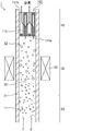
- FIG. 6 is a cross-sectional view schematically showing an embodiment of a droplet dispersion step and a carrier gas inflow step.
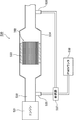
- FIG. 7 is an explanatory diagram of a collection efficiency measuring device.
- FIG. 8 is an explanatory diagram of a pressure loss measuring device.
- the honeycomb filter according to the first embodiment of the present invention A ceramic honeycomb substrate in which a large number of cells for circulating a fluid are arranged side by side in the longitudinal direction across a cell wall, and either the fluid inflow side or the fluid outflow side of the cell is sealed; Of the surface of the cell wall, a filtration layer formed on the surface of the cell wall of the cell in which the end portion on the fluid inflow side is opened and the end portion on the fluid outflow side is sealed; An SCR catalyst carried on the surface of the cell wall of the cell in which the end portion on the fluid inflow side is sealed and the end portion on the fluid outflow side is opened in the cell wall in which the filtration layer is formed; When the average pore diameter of the pores of the filtration layer is a ( ⁇ m) and the average particle diameter of the particles constituting the SCR catalyst is b ( ⁇ m), a portion satisfying a ⁇ b is included.
- the ceramic honeycomb substrate (ceramic block) is composed of a plurality of honeycomb fired bodies.
- a large number of cells included in the honeycomb fired body constituting the honeycomb filter are composed of large-capacity cells and small-capacity cells, and the cross-sectional area perpendicular to the longitudinal direction of the large-capacity cells is perpendicular to the longitudinal direction of the small-capacity cells. Larger than the cross-sectional area.
- the honeycomb filter according to the first embodiment of the present invention is obtained by forming a filtration layer on the surface of a cell wall of a ceramic honeycomb substrate including a honeycomb fired body.
- ceramic honeycomb substrate those having a filtration layer formed on the surface of the cell wall
- honeycomb filter those having the filtration layer formed on the cell wall are referred to as “honeycomb filter”.
- cross section of the honeycomb fired body when the cross section of the honeycomb fired body is simply indicated, it indicates a cross section perpendicular to the longitudinal direction of the honeycomb fired body. Similarly, when simply expressed as the cross-sectional area of the honeycomb fired body, it refers to the area of the cross section perpendicular to the longitudinal direction of the honeycomb fired body.
- FIG. 1 is a perspective view schematically showing an example of the honeycomb filter according to the first embodiment of the present invention.
- Fig.2 (a) is a perspective view which shows typically an example of the honeycomb fired body which comprises the honeycomb filter shown in FIG.
- FIG. 2B is a cross-sectional view taken along the line AA of the honeycomb fired body shown in FIG.
- FIG. 3 is a partially enlarged sectional view of the cell wall of the honeycomb fired body shown in FIGS. 2 (a) and 2 (b).
- honeycomb filter 100 a plurality of honeycomb fired bodies 110 are bound via an adhesive layer 101 to form a ceramic honeycomb substrate (ceramic block) 103, and this ceramic honeycomb substrate (ceramic block) ) On the outer periphery of 103, an outer peripheral coat layer 102 for preventing the leakage of exhaust gas is formed. In addition, the outer periphery coating layer should just be formed as needed.
- a honeycomb filter formed by binding a plurality of honeycomb fired bodies is also referred to as a collective honeycomb filter.
- the honeycomb fired body 110 constituting the honeycomb filter 100 will be described later, it is preferably a porous body made of silicon carbide or silicon-containing silicon carbide.
- a large number of cells 111a and 111b are arranged in the longitudinal direction (in the direction of arrow a in FIG. 2 (a)) across the cell wall 113. And an outer peripheral wall 114 is formed on the outer periphery thereof. One end of the cells 111a and 111b is sealed with a sealing material 112a or 112b.
- a filtration layer 115 is formed on the surface of the cell wall 113 of the honeycomb fired body 110.
- the SCR catalyst 116 is supported on the cell wall 113 of the honeycomb fired body 110.
- the filter layer 115 and the SCR catalyst 116 are not shown.
- the SCR catalyst 116 is not shown.
- a large-capacity cell 111a whose cross-sectional area perpendicular to the longitudinal direction is relatively larger than the small-capacity cell 111b, and a cross-section perpendicular to the longitudinal direction.
- small-capacity cells 111b whose area is relatively smaller than that of the large-capacity cell 111a.
- the shape of the cross section perpendicular to the longitudinal direction of the large capacity cell 111a is substantially octagonal, and the shape of the cross section perpendicular to the longitudinal direction of the small capacity cell 111b is substantially square.
- the large-capacity cell 111a is opened at the end portion on the first end face 117a side of the honeycomb fired body 110, and on the second end face 117b side. The end is sealed with a sealing material 112a.
- the small-capacity cell 111b the end portion on the second end face 117b side of the honeycomb fired body 110 is opened, and the end portion on the first end face 117a side is sealed with the sealing material 112b. Therefore, as shown in FIG. 2B, the exhaust gas G 1 flowing into the large-capacity cell 111a (in FIG.
- the exhaust gas is indicated by G 1 and the flow of the exhaust gas is indicated by an arrow) is always large.
- the small capacity cell 111b After passing through the cell wall 113 separating the capacity cell 111a and the small capacity cell 111b, the small capacity cell 111b flows out.
- the exhaust gas G 1 is passing through the cell walls 113, since the PM and the like in the exhaust gas is collected, the cell wall 113 that separates the large-volume cells 111a and small-volume cell 111b functions as a filter.
- gas such as exhaust gas can be circulated through the large-capacity cells 111a and the small-capacity cells 111b of the honeycomb fired body 110.
- a gas such as exhaust gas is circulated in the direction shown in FIG.
- the end of the honeycomb fired body 110 on the first end face 117a side (the end on the side where the small capacity cells 111b are sealed) is fluidized.
- the end on the inflow side is referred to as the end on the second end face 117b side of the honeycomb fired body 110 (the end on the side where the large-capacity cells 111a are sealed) is referred to as the end on the fluid outflow side.
- the large capacity cell 111a having an open end on the fluid inflow side is a cell 111a on the fluid inflow side
- the small capacity cell 111b having an end on the fluid outflow side is a cell on the fluid outflow side. 111b.
- the filtration layer is made of ceramic particles, preferably spherical ceramic particles.
- the ceramic particles forming the filtration layer are preferably made of a heat-resistant oxide.
- the heat-resistant oxide include alumina, silica, mullite, ceria, cordierite, zirconia, and titania. These may be used alone or in combination of two or more. Of the above heat-resistant oxides, alumina is preferable.
- the average particle size of the particles constituting the filtration layer is preferably 0.2 to 1.2 ⁇ m, more preferably 0.2 to 0.9 ⁇ m. Preferably, it is 0.5 to 0.8 ⁇ m.
- the average particle diameter of the particles constituting the filtration layer is less than 0.2 ⁇ m, the particles constituting the filtration layer are too small, and thus the filtration layer is hardly formed on the surface of the cell wall.
- the average particle diameter of the particles constituting the filtration layer is less than 0.2 ⁇ m, the particles constituting the filtration layer may enter the inside (pores) of the cell wall and block the pores. Loss may increase.
- the average particle diameter of the particles constituting the filtration layer exceeds 1.2 ⁇ m, the particles constituting the filtration layer are too large, so even if the filtration layer is formed, the pore size of the filtration layer is increased. Therefore, PM passes through the filtration layer and enters the pores of the cell wall, resulting in a “depth filtration” state in which PM is collected inside the cell wall, and the pressure loss increases.
- grains which comprise a filtration layer can be measured with the following method.
- a honeycomb fired body constituting the honeycomb filter is processed to prepare a sample of 10 mm ⁇ 10 mm ⁇ 10 mm.
- the surface of the sample is observed with a scanning electron microscope (SEM) at any one location of the prepared sample.
- SEM scanning electron microscope
- the particles constituting the filtration layer are set within one field of view.
- the observation conditions of SEM are acceleration voltage: 15.00 kV, working distance (WD): 15.00 mm, and magnification: 10,000 times.
- the particle diameters of all the particles in one field of view are visually measured.
- the average value of the particle diameters of all the particles measured within one field of view is defined as “the average particle diameter of the particles constituting the filtration layer”.
- a when the average pore diameter of the pores of the filtration layer is a, a is preferably 0.5 to 3.0 ⁇ m, and 0.7 to 2. It is more preferably 0 ⁇ m, and further preferably 1.0 to 1.9 ⁇ m. If a is less than 0.5 ⁇ m, the gas is difficult to permeate the filtration layer, and the permeation resistance increases. On the other hand, when a exceeds 3.0 ⁇ m, it becomes difficult for PM to pass through the filtration layer, so that it is difficult to obtain sufficient PM collection efficiency.
- the average pore diameter a of the pores of the filtration layer can be measured by the following method.
- the honeycomb fired body constituting the honeycomb filter is processed to produce a 10 mm ⁇ 10 mm ⁇ 10 mm sample.
- the surface of the sample is observed with a scanning electron microscope (SEM) at any one location of the prepared sample.
- SEM scanning electron microscope
- the observation conditions of SEM are acceleration voltage: 15.00 kV, working distance (WD): 15.00 mm, and magnification: 10,000 times.
- the obtained SEM photograph is binarized, and the diameter of a circle inscribed in the gap between the particles is measured at 10 or more locations.
- the measured average value of the diameter of the inscribed circle is defined as “average pore diameter a of pores of the filtration layer”.
- the filtration layer may contain hollow particles.
- the thickness of the filtration layer is preferably 3 to 60 ⁇ m, more preferably 5 to 40 ⁇ m, and still more preferably 10 to 25 ⁇ m.
- the thickness of the filtration layer is less than 3 ⁇ m, the filtration layer is too thin, so that PM is hardly collected.
- the thickness of the filtration layer exceeds 60 ⁇ m, the filtration layer is too thick, and the pressure loss is likely to increase.
- it is preferable that the thickness of the filtration layer is constant.
- FIG. 4 is a schematic diagram for explaining a method of measuring the thickness of the filtration layer.
- the honeycomb fired body constituting the honeycomb filter is processed to produce a 10 mm ⁇ 10 mm ⁇ 10 mm sample.
- the cell cross section is observed with a scanning electron microscope (SEM) at any one location of the prepared sample.
- SEM scanning electron microscope
- the observation conditions of SEM are acceleration voltage: 15.00 kV, working distance (WD): 15.00 mm, and magnification: 500 to 1000 times.
- FIG. 4 for the sake of easy understanding, a schematic diagram is shown instead of an actual SEM photograph.
- FIG. 4 for the sake of easy understanding, a schematic diagram is shown instead of an actual SEM photograph.
- the filtration layer is formed only on the surface of the cell wall of the cell in which the end on the fluid inflow side is opened and the end on the fluid outflow side is sealed. . Since the exhaust gas flows into the cell from the fluid inflow side of the honeycomb filter, a large amount of PM in the exhaust gas accumulates on the cell wall of the cell where the end on the fluid inflow side is opened and the end on the fluid outflow side is sealed. Is done. Therefore, when the filtration layer is formed only on the surface of the cell wall of the cell in which the end on the fluid inflow side is opened and the end on the fluid outflow side is sealed, PM is collected by the filtration layer. Therefore, depth filtration can be prevented.
- the filtration layer is formed on the entire surface of the cell wall of the cell in which the end on the fluid inflow side is opened and the end on the fluid outflow side is sealed. However, there may be a portion where the filtration layer is not formed on a part of the surface of the cell wall.
- the SCR catalyst is also called a selective reduction type NOx catalyst, and reduces and purifies NOx in exhaust gas using ammonia.
- the SCR catalyst has a function of adsorbing urea and ammonia.
- the SCR catalyst is preferably zeolite.
- the supported amount of the SCR catalyst is preferably 80 to 200 g / L, more preferably 100 to 200 g / L, and more preferably 100 to 150 g / L. More preferably.
- the supported amount of SCR catalyst is 80 to 200 g / L, NOx in the exhaust gas can be sufficiently purified when the honeycomb filter is used in a urea SCR device.
- the supported amount of the SCR catalyst is less than 80 g / L, the NOx purification performance as a honeycomb filter for the urea SCR device is not sufficient.
- the loading amount of the SCR catalyst exceeds 200 g / L, the SCR catalyst closes the cell, and the pressure loss is likely to increase even when PM is not deposited.
- the loading amount of the SCR catalyst means the weight of the SCR catalyst per liter of the apparent volume of the honeycomb filter.
- the apparent volume of the honeycomb filter includes the volume of the adhesive layer and / or the outer peripheral coat layer.
- b when the average particle diameter of the particles constituting the SCR catalyst is b, b is preferably 0.7 to 5.0 ⁇ m, and 2.0 to 4 The thickness is more preferably 0.0 ⁇ m, and even more preferably 2.1 to 4.0 ⁇ m.
- b is less than 0.7 ⁇ m, the particles constituting the SCR catalyst are too small, and the particles are likely to clog the filtration layer.
- b exceeds 5.0 ⁇ m, the particles constituting the SCR catalyst are less likely to be clogged in the filtration layer, but the specific surface area of the particles is small, so that it is difficult to obtain a sufficient NOx purification rate.
- the average particle diameter b of the particles constituting the SCR catalyst can be measured by the same method as the average particle diameter of the particles constituting the filtration layer. When the average particle diameter b is measured, SEM observation may be performed so that the particles constituting the SCR catalyst fall within one field of view. In addition, the average particle diameter b can be substituted with an average particle diameter obtained from particles (for example, zeolite particles contained in a zeolite slurry described later) constituting the SCR catalyst before being supported on the ceramic honeycomb substrate. .
- the SCR catalyst is a cell wall in which a filtration layer is formed, the end of the fluid inflow side is sealed, and the end of the fluid outflow side is opened. It is carried on the surface of the cell wall.
- the SCR catalyst is supported on the entire surface of the cell wall of the cell in which the end on the fluid inflow side is sealed and the end on the fluid outflow side is opened. However, it is possible that a part of the surface of the cell wall does not support the SCR catalyst.
- the SCR catalyst may be further supported on the pores of the cell walls of the ceramic honeycomb substrate.
- the SCR catalyst is further supported on the surface of the cell wall of the cell in which the end on the fluid inflow side is opened and the end on the fluid outflow side is sealed. Also good.
- the SCR catalyst has an end on the fluid inflow side that is open and an end on the fluid inflow side is sealed from the surface side of the cell wall of the cell that is sealed at the end on the fluid outflow side. It is preferable that a large number of the side ends are supported on the surface side of the cell wall of the opened cell. In this case, contact between the collected PM and the SCR catalyst can be prevented.
- the SCR catalyst is preferably not supported on the surface of the filtration layer. In this case, the deterioration of the SCR catalyst due to heat can be suppressed when the regeneration process for burning PM is performed.
- the honeycomb filter according to the first embodiment of the present invention includes a portion satisfying a ⁇ b, where a is the average pore diameter of the pores of the filtration layer and b is the average particle diameter of the particles constituting the SCR catalyst. It is characterized by being.
- the entire honeycomb filter may not satisfy a ⁇ b, and a part of the honeycomb filter only needs to satisfy a ⁇ b.
- the portion satisfying a ⁇ b may be 60% or less of the whole honeycomb filter or 40% or less.
- the portion satisfying a ⁇ b is preferably 20% or more of the whole honeycomb filter, and more preferably 30% or more.
- the porosity of the cell wall is preferably 55 to 70%.
- the porosity of the cell wall of the ceramic honeycomb substrate is 55 to 70%, a large amount of SCR catalyst can be supported on the cell wall.
- the porosity of the cell wall is less than 55%, when a large amount of the SCR catalyst is supported on the ceramic honeycomb substrate, the SCR catalyst is clogged in the pore portion of the cell wall, and the exhaust gas does not easily pass through the cell wall. The exhaust gas is less likely to diffuse and the action of the SCR catalyst is not sufficiently exhibited.
- the porosity of the cell wall exceeds 70%, the strength of the ceramic honeycomb substrate tends to decrease.
- the average pore diameter of the cell wall is preferably 15 to 30 ⁇ m.
- the average pore diameter of the cell wall is less than 15 ⁇ m, the pressure loss after the SCR catalyst is supported on the cell wall tends to increase.
- the average pore diameter of the cell wall exceeds 30 ⁇ m, it becomes difficult to form a filtration layer on the surface of the cell wall.
- the porosity and pore diameter can be measured by a conventionally known mercury intrusion method.
- the thickness of the cell wall is preferably 0.12 to 0.40 mm, and more preferably 0.20 to 0.30 mm.
- the cell wall thickness is less than 0.12 mm, the cell wall thickness becomes thin, and the strength of the honeycomb fired body cannot be maintained.
- the thickness of the cell wall exceeds 0.40 mm, the pressure loss of the honeycomb structure tends to increase.
- the thickness of a cell wall means the thickness between cells.
- the cell density in the cross section perpendicular to the longitudinal direction of the honeycomb fired body is not particularly limited, but a preferable lower limit is 31.0 cells / cm 2 (200 cells / inch 2). ), A preferred upper limit is 93.0 pieces / cm 2 (600 pieces / inch 2 ), a more preferred lower limit is 38.8 pieces / cm 2 (250 pieces / inch 2 ), and a more preferred upper limit is 77.5 pieces. / Cm 2 (500 pieces / inch 2 ).
- examples of the shape of the cross section perpendicular to the longitudinal direction of the large-capacity cell and the small-capacity cell included in the honeycomb fired body include the following shapes.
- 5 (a), 5 (b) and 5 (c) are side views schematically showing an example of the cell structure of the honeycomb fired body constituting the honeycomb filter according to the first embodiment of the present invention.
- the filtration layer is not illustrated in FIGS. 5A, 5B, and 5C.
- the shape of the cross section perpendicular to the longitudinal direction of the large capacity cell 121a is substantially octagonal, and the shape of the cross section perpendicular to the longitudinal direction of the small capacity cell 121b is substantially rectangular.
- the large capacity cells 121a and the small capacity cells 121b are alternately arranged.
- the shape of the cross section perpendicular to the longitudinal direction of the large capacity cell 131a is substantially octagonal, and the shape of the cross section perpendicular to the longitudinal direction of the small capacity cell 131b.
- the honeycomb fired body 120 shown in FIG. 5 (a) and the honeycomb fired body 130 shown in FIG. 5 (b) have a cross section perpendicular to the longitudinal direction of the large capacity cell with respect to the area of the cross section perpendicular to the longitudinal direction of the small capacity cell.
- the area ratio of the areas is different. Further, in the honeycomb fired body 140 shown in FIG.
- the cross-sectional shape perpendicular to the longitudinal direction of the large-capacity cell 141a is substantially square, and the cross-sectional shape perpendicular to the longitudinal direction of the small-capacity cell 141b is substantially
- the large-capacity cells 141a and the small-capacity cells 141b are alternately arranged.
- the area ratio of the area of the cross section perpendicular to the longitudinal direction of the large capacity cell to the area of the cross section perpendicular to the longitudinal direction of the small capacity cell is preferably 1.4 to 2.8, and more preferably 1.5 to 2.4.
- honeycomb filter according to the first embodiment of the present invention Using a ceramic powder, a porous honeycomb fired body in which a large number of cells are arranged in parallel in the longitudinal direction across a cell wall, and either the fluid inflow side or the fluid outflow side of the cell is sealed.
- a honeycomb fired body manufacturing process to be manufactured A filtration layer forming step of forming a filtration layer on the surface of the cell wall; A catalyst application step of supporting the SCR catalyst on the cell wall,
- the filtration layer forming step includes A droplet dispersion step of dispersing droplets containing raw materials of ceramic particles in a carrier gas;
- a carrier gas inflow step for allowing the carrier gas to flow into a cell in which an end on the fluid inflow side is opened and an end on the fluid outflow side is sealed,
- the SCR catalyst is supported on the cell wall by introducing the SCR catalyst into a cell in which the end portion on the fluid inflow side is sealed and the end portion on the fluid outflow side is opened.
- a ceramic honeycomb substrate including a honeycomb fired body is manufactured, and a filtration layer is formed on the surface of the cell wall of the ceramic honeycomb substrate.
- the SCR catalyst is supported on the formed cell wall.
- the filtration layer forming step and the catalyst applying step will be described.
- the case where the material constituting the filtration layer is a heat-resistant oxide will be described as an example.
- the process for producing the ceramic honeycomb substrate including the honeycomb fired body will be described later.
- FIG. 6 is a cross-sectional view schematically showing an embodiment of a droplet dispersion step and a carrier gas inflow step.
- FIG. 6 shows a carrier gas inflow device 1 that is a device for causing a carrier gas to flow into the cells of the ceramic honeycomb substrate.
- the carrier gas inflow device 1 includes a droplet dispersion unit 20 that disperses droplets in the carrier gas, a piping unit 30 through which the carrier gas in which the droplets are dispersed passes, and an inflow unit that flows the carrier gas into the cells of the ceramic honeycomb substrate. 40.
- the droplet dispersion step and the carrier gas inflow step are performed using the carrier gas inflow device 1 will be described.
- the carrier gas F flows from the lower side to the upper side in FIG.
- the carrier gas F is introduced from below the carrier gas inflow device 1, and is discharged from above the inflow portion 40 through the droplet dispersion portion 20, the piping portion 30, and the inflow portion 40.
- the carrier gas F is pressurized from the lower side to the upper side in FIG. 6 by the pressure difference generated by the pressurization from the lower side of the carrier gas inflow device or the suction from the upper side of the carrier gas inflow device. Flows upward in 1.
- a gas that does not react by heating up to 800 ° C. and does not react with the components in the droplets dispersed in the carrier gas is used.
- the carrier gas include gases such as air, nitrogen, and argon.
- an oxide-containing solution filled in a tank (not shown) is formed into droplets 11 by spraying and dispersed in the carrier gas F.
- the oxide-containing solution is a concept including a solution containing a heat-resistant oxide precursor in which a heat-resistant oxide is formed by heating, or a slurry containing heat-resistant oxide particles.
- the heat-resistant oxide precursor means a compound derived from a heat-resistant oxide by heating. Examples thereof include metal hydroxides, carbonates, nitrates, and hydrates constituting the heat-resistant oxide.
- the slurry containing heat-resistant oxide particles is a solution in which heat-resistant oxide particles are suspended in water.
- the droplets 11 dispersed in the carrier gas F ride on the carrier gas F and flow above the carrier gas inflow device 1 and pass through the piping part 30.
- the pipe part 30 of the carrier gas inflow device 1 is a pipe through which the carrier gas F in which the droplets 11 are dispersed passes.
- the passage 32 through which the carrier gas F passes in the pipe portion 30 is a space surrounded by the pipe wall 31 of the pipe.
- a heating mechanism 33 is provided in the piping part 30.
- An example of the heating mechanism 33 is an electric heater.
- the pipe wall 31 is heated using the heating mechanism 33, and the carrier gas F in which the droplets 11 are dispersed is allowed to pass through. And it is preferable to heat the carrier gas F which passes the piping part 30, and to heat the droplet 11 disperse
- FIG. 6 When the droplet 11 is heated, the liquid component contained in the droplet evaporates to form spherical ceramic particles 12. In FIG. 6, the spherical ceramic particles 12 are indicated by white circles.
- the heat-resistant oxide precursor is contained in the droplet, the heat-resistant oxide precursor becomes a heat-resistant oxide (spherical ceramic particles) by heating the carrier gas.
- the pipe wall 31 is heated to 100 to 800 ° C. using the heating mechanism 33 and the carrier gas F in which the droplets 11 are dispersed is allowed to pass for 0.1 to 3.0 seconds. If the temperature of the heated pipe is less than 100 ° C. and the time for allowing the carrier gas to pass through the pipe is less than 0.1 seconds, it becomes difficult to sufficiently evaporate the water in the droplets. On the other hand, if the temperature of the heated pipe exceeds 800 ° C. and the time for passing the carrier gas through the pipe exceeds 3.0 seconds, the energy required for manufacturing the honeycomb filter becomes too large. The manufacturing efficiency of the honeycomb filter is reduced.
- the length of the pipe is not particularly limited, but is preferably 500 to 3000 mm. If the length of the pipe is less than 500 mm, it becomes difficult to sufficiently evaporate the water in the droplets even if the speed of passing the carrier gas through the pipe is slowed. On the other hand, if the length of the pipe exceeds 3000 mm, the apparatus for manufacturing the honeycomb filter becomes too large, and the manufacturing efficiency of the honeycomb filter is lowered.
- the spherical ceramic particles 12 ride on the flow of the carrier gas F and flow above the carrier gas inflow device 1, and flow into the cells of the ceramic honeycomb substrate 103 at the inflow portion 40.
- a ceramic block in which a plurality of honeycomb fired bodies are bound through an adhesive layer is used as the ceramic honeycomb substrate.
- the ceramic honeycomb substrate 103 is arranged at the upper part of the carrier gas inflow device 1 so as to close the outlet of the carrier gas inflow device 1. Therefore, the carrier gas F always flows into the ceramic honeycomb substrate 103.
- FIG. 6 schematically shows a cross section of the honeycomb fired body constituting the ceramic block (a cross section similar to that shown in FIG. 2B) as a cross section of the ceramic honeycomb substrate 103.
- the end portion of the cell 111a on the fluid inflow side is open, and the cell 111b on the fluid outflow side is sealed. Therefore, the carrier gas F flows into the ceramic honeycomb substrate 103 from the opening of the cell 111a on the fluid inflow side.
- the carrier gas F in which the spherical ceramic particles 12 are dispersed flows into the cell 111 a on the fluid inflow side of the ceramic honeycomb substrate 103, the spherical ceramic particles 12 are deposited on the surface of the cell wall 113 of the ceramic honeycomb substrate 103.
- the ceramic honeycomb substrate 103 is heated to 100 to 800 ° C. and the carrier gas F is allowed to flow into the heated cell.
- the ceramic honeycomb substrate 103 is heated to 100 to 800 ° C., even if the liquid component remains in the spherical ceramic particles 12, the liquid component evaporates, and the surface of the cell wall is in a dry powder state. To deposit.
- the carrier gas F flows into the inside of the ceramic honeycomb substrate 103 from the opening of the cell 111a on the fluid inflow side, passes through the cell wall 113 of the ceramic honeycomb substrate 103, and flows out from the opening of the cell 111b on the fluid outflow side.
- the carrier gas inflow process is performed by such a procedure.
- the spherical ceramic particles can be deposited on the surface of the cell wall by the carrier gas inflow process.
- the ceramic honeycomb substrate it is preferable to perform a heating process of the ceramic honeycomb substrate. It is preferable to heat the ceramic honeycomb substrate on which the spherical ceramic particles are adhered to the cell walls through the carrier gas inflow process at a furnace temperature of 900 to 1500 ° C. using a heating furnace.
- the heating atmosphere is preferably an air atmosphere, a nitrogen atmosphere, or an argon atmosphere.
- the spherical ceramic particles adhering to the surface of the cell wall cause heat shrinkage by heat sintering and firmly adhere to the surface of the cell wall.
- a filtration layer can be formed on the surface of the cell wall.
- the step of heating the carrier gas drying step
- the SCR catalyst is supported on the cell wall by introducing the SCR catalyst into the cell in which the end on the fluid inflow side is sealed and the end on the fluid outflow side is opened.
- Examples of the method for supporting the SCR catalyst on the cell wall include a method in which the ceramic honeycomb substrate is immersed in a slurry containing the SCR catalyst and then heated by heating.
- the amount of the SCR catalyst supported can be adjusted by, for example, a method of repeating the step of immersing the ceramic honeycomb substrate in the slurry and the step of heating, or a method of changing the slurry concentration.
- the average particle diameter b of the particles constituting the SCR catalyst can be adjusted by controlling the particle size of the particles constituting the SCR catalyst contained in the slurry.
- the particle size of the particles constituting the SCR catalyst contained in the slurry is adjusted so that the average particle size b of the particles constituting the SCR catalyst is larger than the average pore size a of the pores of the filter layer that has been obtained in advance. do it.
- the other end is sealed only in the cell (large capacity cell) on the fluid inflow side, and then the ceramic honeycomb substrate is immersed in the slurry containing the SCR catalyst.
- the cell wall forming the fluid inflow side cell Only after the catalyst is attached to the cell wall forming one cell in the same procedure as the procedure for supporting the SCR catalyst, the SCR catalyst is also supported on the cell wall forming the other cell. Changing the immersion time of the ceramic honeycomb substrate in the slurry containing the catalyst, changing the concentration of the slurry, or increasing the particle size of the catalyst in the slurry, and injecting the slurry into the cell on the fluid inflow side And a method of changing the concentration by air blow after the slurry is attached.
- the ceramic honeycomb substrate produced below is a ceramic block in which a plurality of honeycomb fired bodies are bundled through an adhesive layer.
- silicon carbide used as the ceramic powder.
- a forming step for producing a honeycomb formed body by extruding a wet mixture containing a ceramic powder and a binder is performed. Specifically, first, a wet mixture for manufacturing a honeycomb formed body is prepared by mixing silicon carbide powder having different average particle sizes as ceramic powder, an organic binder, a liquid plasticizer, a lubricant, and water. To prepare.
- a honeycomb formed body having a predetermined shape.
- a honeycomb formed body is manufactured using a mold that has a cross-sectional shape having a cell structure (cell shape and cell arrangement) shown in FIGS. 2 (a) and 2 (b).
- the honeycomb formed body is cut to a predetermined length, dried using a microwave dryer, hot air dryer, dielectric dryer, vacuum dryer, vacuum dryer, freeze dryer, etc.
- a sealing step of filling the cell with a sealing material paste as a sealing material and sealing the cell is performed.
- the wet mixture can be used as the sealing material paste.
- the degreased honeycomb formed body is conveyed to a firing furnace, and the firing step is performed.
- a honeycomb fired body as shown in FIGS. 2A and 2B is manufactured.
- the sealing material paste with which the edge part of the cell was filled is baked by heating and becomes a sealing material.
- the conditions currently used when manufacturing a honeycomb fired body can be applied to the conditions of a cutting process, a drying process, a sealing process, a degreasing process, and a firing process.
- a bundling process is performed in which a plurality of honeycomb fired bodies are sequentially stacked and bonded via an adhesive paste on a support stand to produce a honeycomb aggregate in which a plurality of honeycomb fired bodies are stacked.
- the adhesive paste for example, a paste made of an inorganic binder, an organic binder, and inorganic particles is used.
- the adhesive paste may further contain inorganic fibers and / or whiskers.
- honeycomb aggregate is heated and the adhesive paste is heated and solidified to form an adhesive layer, thereby producing a quadrangular columnar ceramic block.
- the conditions for heating and solidifying the adhesive paste the conditions conventionally used when producing a honeycomb filter can be applied.
- a cutting process for cutting the ceramic block is performed. Specifically, a ceramic block whose outer periphery is processed into a substantially cylindrical shape is manufactured by cutting the outer periphery of the ceramic block using a diamond cutter.
- An outer peripheral coating layer forming step is performed in which an outer peripheral coating material paste is applied to the outer peripheral surface of the substantially cylindrical ceramic block, and dried and solidified to form an outer peripheral coating layer.
- the said adhesive paste can be used as an outer periphery coating material paste.
- the outer peripheral coat layer is not necessarily provided, and may be provided as necessary.
- honeycomb filter which concerns on 1st embodiment of this invention is producible by performing the filtration layer formation process and catalyst provision process which were mentioned above with respect to the ceramic honeycomb base material.
- the honeycomb filter of the present embodiment includes a portion satisfying a ⁇ b, where a is the average pore diameter of the pores of the filtration layer and b is the average particle diameter of the particles constituting the SCR catalyst. It is said.
- a is the average pore diameter of the pores of the filtration layer
- b is the average particle diameter of the particles constituting the SCR catalyst.
- a carrier gas containing ceramic particles formed in the drying step and the like described later is caused to flow into the cell from the fluid inflow side. Therefore, ceramic particles are deposited on the surface of the cell wall of the cell in which the end portion on the fluid inflow side is opened and the end portion on the fluid outflow side is sealed, and a filtration layer is formed.
- the SCR catalyst is introduced into the cell from the fluid outflow side, that is, the side opposite to the side into which the carrier gas is introduced in the carrier gas inflow step.
- the direction in which the carrier gas is introduced in the carrier gas inflow process is opposite to the direction in which the SCR catalyst is introduced in the catalyst application process. Accordingly, the SCR catalyst is supported only on the cell wall of the cell wall and the filtration layer, or is supported on both the cell wall and the filtration layer, and the amount of the SCR catalyst supported on the cell wall is reduced.
- the amount per unit volume is larger than the amount of the SCR catalyst supported on the filtration layer. Therefore, the amount of the SCR catalyst that is far from the collected PM can be increased. That is, when the regeneration process for burning PM is performed, the amount of the SCR catalyst that does not deteriorate due to heat can be increased, so that the NOx purification function can be ensured over a long period of time.
- the honeycomb filter manufacturing method of the present embodiment includes a portion satisfying a ⁇ b, where a is the average pore diameter of the pores of the filtration layer and b is the average particle diameter of the particles constituting the SCR catalyst.
- a honeycomb filter is manufactured. Therefore, the SCR catalyst can be prevented from clogging the filtration layer in the catalyst application step. As a result, a honeycomb filter with low pressure loss can be manufactured.
- Example 2 Examples of the honeycomb filter and the method for manufacturing the honeycomb filter according to the first embodiment of the present invention will be described below more specifically. In addition, this invention is not limited only to these Examples.
- Example 1 (Production of ceramic honeycomb substrate) First, 54.6% by weight of a coarse powder of silicon carbide having an average particle diameter of 22 ⁇ m and 23.4% by weight of a fine powder of silicon carbide having an average particle diameter of 0.5 ⁇ m were mixed. An organic binder (methylcellulose) 4.3 wt%, a lubricant (Unilube made by NOF Corporation) 2.6 wt%, glycerin 1.2 wt%, and water 13.9 wt% are added and kneaded to obtain a wet mixture. After being obtained, a molding step of extrusion molding was performed. In this step, a raw honeycomb molded body having the same shape as the honeycomb fired body 110 shown in FIG. 2A and having no cell plugged was produced.
- a lubricant Unilube made by NOF Corporation
- the raw honeycomb formed body was dried using a microwave dryer, thereby manufacturing a dried body of the honeycomb formed body.
- the sealing material paste was filled in predetermined cells of the dried honeycomb molded body to seal the cells.
- the wet mixture was used as a sealing material paste.
- the dried honeycomb molded body filled with the plug paste was again dried using a dryer.
- the manufactured honeycomb fired body has a height of 34.3 mm ⁇ a width of 34.3 mm ⁇ a length of 150 mm, an average pore diameter of 24 ⁇ m, a porosity of 64%, and the number of cells (cell density) of 54.2 cells / cm 2 ( 350 cells / inch 2 ) and the cell wall thickness was 0.28 mm (11 mil).
- honeycomb fired bodies By applying an adhesive paste between the honeycomb fired bodies obtained by the above process to form an adhesive paste layer, and heating and solidifying the adhesive paste layer to form an adhesive layer, 16 honeycomb fired bodies are obtained. A substantially prismatic ceramic block formed by binding through an adhesive layer was produced.
- As the adhesive paste 30% by weight of alumina fibers having an average fiber length of 20 ⁇ m, 21% by weight of silicon carbide particles having an average particle diameter of 0.6 ⁇ m, 15% by weight of silica sol, 5.6% by weight of carboxymethylcellulose, and water 28 An adhesive paste containing 4% by weight was used.
- a cylindrical ceramic block having a diameter of 142 mm was prepared by cutting the outer periphery of the prismatic ceramic block using a diamond cutter.
- the outer peripheral coating material paste was applied to the outer peripheral surface of the columnar ceramic block, and the outer peripheral coating material paste was heated and solidified at 120 ° C. to form an outer peripheral coating layer on the outer peripheral portion of the ceramic block.
- the paste similar to the said adhesive material paste was used as the said outer periphery coating material paste.
- a filter layer was formed on the ceramic honeycomb substrate using the carrier gas inflow device shown in FIG. As shown in FIG. 6, a ceramic honeycomb substrate was disposed above the carrier gas inflow device. At this time, the ceramic honeycomb substrate was disposed with the opening of a large-capacity cell as a cell on the fluid inflow side facing downward of the carrier gas inflow device.
- a solution containing boehmite which is a heat-resistant oxide precursor was prepared.
- the concentration of boehmite was 3.8 mol / L (solid content concentration: 20% by weight). Then, the droplets containing boehmite were dispersed in the carrier gas by spraying.
- the temperature of the wall of the pipe of the carrier gas inflow device is heated to 200 ° C., and the carrier gas is flowed at a flow rate of 4.6 mm / sec toward the upper side (ceramic honeycomb substrate side) of the carrier gas inflow device.
- the water in the droplets dispersed therein was evaporated.
- the length of the pipe was 1200 mm.
- the carrier gas in which the spherical alumina particles were dispersed was allowed to flow into the cells of the ceramic honeycomb substrate, and 5 g / L of spherical alumina particles were adhered to the surface of the cell walls. Thereafter, the ceramic honeycomb substrate was taken out from the carrier gas inflow device and heated in a firing furnace at 1350 ° C. for 3 hours in an air atmosphere. Through the above process, a filtration layer made of alumina particles was formed on the surface of the cell wall.
- ⁇ -type zeolite powder ion-exchanged with iron ions was mixed with a sufficient amount of water, and further pulverized with a ball mill at 90 min ⁇ 1 to prepare a zeolite slurry.
- the particle diameter of the zeolite was adjusted by changing the particle diameter of the raw material powder and the pulverization time.
- a ceramic honeycomb substrate having a filtration layer formed on the surface of the cell wall was immersed with the opening of a small-capacity cell as a cell on the fluid outflow side facing downward, and held for 1 minute. Then, the drying process which heats this ceramic honeycomb base material for 1 hour at 110 degreeC was performed, and also the baking process for baking for 1 hour at 700 degreeC was performed, and the SCR catalyst was carry
- Example 1 When preparing the zeolite slurry, a honeycomb filter was produced in the same manner as in Example 1 except that the pulverization time was longer than that in Example 1 to make the zeolite particle size smaller than that in Example 1.
- FIG. 7 is an explanatory diagram of a collection efficiency measuring device.
- the collection efficiency measuring device 530 includes a 1.6 L (liter) diesel engine 531, an exhaust gas pipe 532 that distributes exhaust gas from the engine 531, and a honeycomb filter 100 that is connected to the exhaust gas pipe 532 and wound with an alumina mat 533.
- the metal casing 534 to be fixed, the sampler 535 that samples the exhaust gas before flowing through the honeycomb filter 100, the sampler 536 that samples the exhaust gas after flowing through the honeycomb filter 100, and the exhaust gas sampled by the samplers 535 and 536 is diluted.
- Scanning mobility particle size analyzer (Scanning Mobility P) equipped with a diluter 537 and a PM counter 538 (aggregated particle counter 3022A-S manufactured by TSI) for measuring the amount of PM contained in the diluted exhaust gas rticle Sizer SMPS) is configured as.
- the NOx purification rate was measured for each honeycomb filter.
- one honeycomb fired body (34.3 mm ⁇ 34.3 mm ⁇ 150 mm) was cut out from the honeycomb filter of Example 1 and Comparative Example 1 by using a diamond cutter, and the cut honeycomb The fired body was further cut to prepare a cylindrical short body of ⁇ 1 inch (25.4 mm) ⁇ 3 inches (76.2 mm). In the produced short body, either one end of the cell was sealed, and this short body was used as a sample for NOx purification rate measurement.
- the NOx purification rate was measured using a NOx purification rate measuring device (Catalyst evaluation device SIGU-2000 manufactured by Horiba, Ltd.).
- the NOx purification rate measuring device is composed of a gas generation part and a reaction part, and the pseudo exhaust gas and ammonia generated in the gas generation part are circulated through the reaction part in which a sample for NOx purification rate measurement is set.
- the above composition was obtained by adjusting the flow rate of each gas using a flow rate controller. Further, the temperature of the reaction part was kept constant at 150 ° C.
- the space velocity (SV) was set to 70000 hr ⁇ 1 as a condition for the zeolite to contact the pseudo exhaust gas and ammonia.
- the NOx purification rate was measured.
- NOx purification rate (%) [(N 0 ⁇ N 1 ) / N 0 ] ⁇ 100 The obtained measurement results are shown in Table 1.
- FIG. 8 is an explanatory diagram of a pressure loss measuring device.
- the pressure loss measuring device 510 can detect the pressure before and after the honeycomb filter 100 by disposing the honeycomb filter 100 in the metal casing 513 in the exhaust gas pipe 512 of a 1.6 L (liter) diesel engine 511.
- a pressure gauge 514 is attached so that The engine 511 was operated at a torque of 50 Nm and a rotation speed of 3000 rpm, and the differential pressure in a state where PM was not deposited on the honeycomb filter 100, that is, the initial pressure loss was measured.
- the obtained measurement results are shown in Table 1.
- the average pore diameter a of the pores of the filtration layer in the honeycomb filter of Example 1 and Comparative Example 1, the average particle diameter b of the particles constituting the SCR catalyst, the collection efficiency, the NOx purification rate, and the initial pressure loss are summarized. It is shown in Table 1 below.
- the NOx purification rate of the honeycomb filter of Comparative Example 1 is a low value of 48%, whereas the NOx purification rate of the honeycomb filter of Example 1 is a high value of 55%.
- the average pore diameter “a” of the pores of the filtration layer is larger than the average particle diameter “b” of the particles (zeolite particles) constituting the SCR catalyst. Therefore, it is considered that a part of the zeolite particles enters the filtration layer. As a result, the zeolite particles that have entered the filtration layer are exposed to high temperatures and deteriorate, and the NOx purification rate decreases.
- the honeycomb filter of Example 1 since the average pore diameter a is smaller than the average particle diameter b, it is considered that the zeolite particles hardly enter the filtration layer. Therefore, a high NOx purification rate can be maintained.
- the initial pressure loss in the honeycomb filter of Comparative Example 1 was a high value of 15 kPa, whereas the initial pressure loss rate in the honeycomb filter of Example 1 was a low value of 10 kPa.
- the honeycomb filter of Example 1 since the average pore diameter a is smaller than the average particle diameter b, it is considered that the zeolite particles are less likely to clog the filtration layer. For this reason, it is considered that an increase in pressure loss can be prevented.
- the honeycomb filter of Example 1 by including a portion where the average pore diameter a is smaller than the average particle diameter b, it is excellent in PM collection efficiency and NOx purification rate, and suppresses an increase in pressure loss. Can do.
- the filtration layer is formed only on the surface of the cell wall of the cell in which the end portion on the fluid inflow side is opened and the end portion on the fluid outflow side is sealed.
- the filtration layer has an opening at the end on the fluid inflow side and a surface of the cell wall of the cell where the end on the fluid outflow side is sealed, The end portion on the fluid inflow side may be sealed, and the end portion on the fluid outflow side may be formed on the surface of the cell wall of the cell.
- Such a honeycomb filter can be manufactured by immersing the ceramic honeycomb substrate in a slurry containing spherical ceramic particles prepared in advance and then heating.
- the droplets may contain heat-resistant oxide particles as a raw material for the ceramic particles.
- the moisture in the droplets can be removed by heating the carrier gas to obtain heat-resistant oxide particles.
- grains of a heat resistant oxide can be formed by flowing the particle
- the filtration layer comprised of the particles of the heat-resistant oxide can also be formed by removing the moisture in the droplets after flowing the droplet containing the heat-resistant oxide particles into the cell.
- the shape of the cross section perpendicular to the longitudinal direction of the cells of the honeycomb fired body constituting the honeycomb filter may be all equal, or at one end face of the honeycomb fired body.
- the cross-sectional areas perpendicular to the longitudinal direction of the sealed cell and the opened cell may be equal to each other.
- the ceramic honeycomb substrate may be composed of one honeycomb fired body.
- a honeycomb filter made of one honeycomb fired body is also referred to as an integral honeycomb filter.
- cordierite or aluminum titanate can be used as the main constituent material of the integral honeycomb filter.
- the shape of the cross section perpendicular to the longitudinal direction of the honeycomb fired body of each cell of the honeycomb fired body is not limited to a substantially square shape, for example, a substantially circular shape or a substantially elliptical shape. Any shape such as a substantially pentagon, a substantially hexagon, a substantially trapezoid, or a substantially octagon may be used. Various shapes may be mixed.
- the filtration layer is formed on the surface of the cell wall of the ceramic honeycomb substrate, the SCR catalyst is supported on the cell wall of the ceramic honeycomb substrate, and the filtration layer has
- the average pore diameter of the pores is a ( ⁇ m) and the average particle diameter of the particles constituting the SCR catalyst is b ( ⁇ m)
- the essential components include various configurations described in detail in the first embodiment and the other embodiments (for example, the configuration of the filtration layer, the method of forming the filtration layer, the cell structure of the honeycomb fired body, the manufacture of the honeycomb filter) Desired effects can be obtained by appropriately combining the steps and the like.
Landscapes
- Chemical & Material Sciences (AREA)
- Engineering & Computer Science (AREA)
- Ceramic Engineering (AREA)
- Chemical Kinetics & Catalysis (AREA)
- Physics & Mathematics (AREA)
- Geometry (AREA)
- Materials Engineering (AREA)
- Organic Chemistry (AREA)
- Structural Engineering (AREA)
- Inorganic Chemistry (AREA)
- General Engineering & Computer Science (AREA)
- Combustion & Propulsion (AREA)
- Mechanical Engineering (AREA)
- Health & Medical Sciences (AREA)
- Environmental & Geological Engineering (AREA)
- Manufacturing & Machinery (AREA)
- Toxicology (AREA)
- Oil, Petroleum & Natural Gas (AREA)
- General Chemical & Material Sciences (AREA)
- Analytical Chemistry (AREA)
- Biomedical Technology (AREA)
- Life Sciences & Earth Sciences (AREA)
- Geology (AREA)
- Exhaust Gas Treatment By Means Of Catalyst (AREA)
- Catalysts (AREA)
- Exhaust Gas After Treatment (AREA)
- Filtering Materials (AREA)
- Civil Engineering (AREA)
Description
本発明は、ハニカムフィルタ及びハニカムフィルタの製造方法に関する。
ディーゼルエンジン等の内燃機関から排出される排ガス中には、スス等のパティキュレート(以下、PMともいう)が含まれており、近年、このPMが環境又は人体に害を及ぼすことが問題となっている。また、排ガス中には、CO、HC及びNOx等の有害なガス成分も含まれていることから、この有害なガス成分が環境又は人体に及ぼす影響についても懸念されている。
そこで、排ガス中のPMを捕集したり、有害なガス成分を浄化したりするために、排ガス浄化装置が用いられている。
このような排ガス浄化装置は、セラミック等の材料からなるハニカム構造体を用いて作製される。ハニカム構造体内に排ガスを通過させることによって排ガスを浄化することができる。
このような排ガス浄化装置は、セラミック等の材料からなるハニカム構造体を用いて作製される。ハニカム構造体内に排ガスを通過させることによって排ガスを浄化することができる。
排ガス浄化装置において排ガス中のPMを捕集するために用いられるハニカム構造体では、多数のセルがセル壁を隔てて長手方向に並設され、セルのいずれか一方の端部が封止されている。そのため、一のセルに流入した排ガスは、必ずセル同士を隔てるセル壁を通過した後、他のセルから流出するようになっている。すなわち、このようなハニカム構造体が排ガス浄化装置に備えられていると、排ガス中に含まれるPMは、ハニカム構造体を通過する際に、セル壁により捕捉される。従って、ハニカム構造体のセル壁は、排ガスが浄化されるフィルタとして機能する。
ハニカム構造体がPMを捕集する初期の段階では、セル壁の細孔にPMが侵入し、セル壁の内部でPMが捕集され、セル壁の細孔が閉塞される「深層濾過」の状態になる。深層濾過の状態では、セル壁の内部(細孔)にPMが堆積していく。そのため、PMの捕集開始直後に、セル壁の実質的な気孔率が低下し、急激に圧力損失が上昇するという問題がある。
一方、排ガス浄化装置において排ガス中のNOxを浄化するために用いられるハニカム構造体として、セルのいずれの端部も封止されておらず、セル壁にNOxを浄化するための触媒が担持されているNOx浄化用のハニカム構造体が用いられている。
近年、排ガス中のNOxを浄化するために、尿素SCR(Selective Catalytic Reduction、選択的触媒還元)装置が提案されている。
尿素SCR装置では、セル壁にゼオライト等のSCR触媒が担持されたハニカム構造体を備えた排ガス浄化装置内に尿素水を噴霧する。そして、尿素の熱分解によってアンモニアを発生させて、ゼオライトの作用によりNOxを還元させる。
このように、尿素SCR装置ではNOxを浄化することができる。
尿素SCR装置では、セル壁にゼオライト等のSCR触媒が担持されたハニカム構造体を備えた排ガス浄化装置内に尿素水を噴霧する。そして、尿素の熱分解によってアンモニアを発生させて、ゼオライトの作用によりNOxを還元させる。
このように、尿素SCR装置ではNOxを浄化することができる。
従来、排ガス中のPMを捕集するために用いられるハニカム構造体とNOx浄化用のハニカム構造体は別の部材からなり、別の金属容器内にそれぞれ配置されており、排気ラインにおいて大きな体積を占めていた。そのため、排ガス浄化装置が占める体積を減らすことが要望されていた。
このような背景の下、排ガス中のPMを捕集するために用いられるハニカム構造体、すなわち、セルのいずれか一方の端部が封止されたハニカム構造体に、ゼオライト等のSCR触媒を担持させたハニカムフィルタの開発が進められている。このようなハニカムフィルタによれば、排ガス中のPMを捕集するとともに、NOxを浄化することが可能である。
特許文献1には、ハニカム構造体のセル壁の気孔率を制御することによって、ハニカムフィルタを尿素SCR装置に用いた場合におけるNOx浄化率を向上させる技術が開示されている。
特許文献1には、ハニカム構造体のセル壁の気孔率を制御することによって、ハニカムフィルタを尿素SCR装置に用いた場合におけるNOx浄化率を向上させる技術が開示されている。
しかしながら、ハニカムフィルタのセル壁に堆積したPMを燃焼し除去する際(再生の際)には、ハニカムフィルタが非常に高温になる。ゼオライト等のSCR触媒は、900℃以上の温度にさらされると、劣化してしまうため、再生を繰り返すたびに、NOx浄化性能が落ちてしまうという問題があった。
本発明は、上記問題点に鑑みてなされたものであり、PMとNOxの双方を浄化することができ、且つ、長期間に亘ってPM及びNOxの浄化機能を確保することが可能なハニカムフィルタ及びその製造方法を提供することを目的とする。
請求項1に記載のハニカムフィルタは、
流体を流通させるための多数のセルがセル壁を隔てて長手方向に並設され、上記セルの流体流入側又は流体流出側のいずれかの端部が封止されてなるセラミックハニカム基材と、
上記セル壁の表面のうち、上記流体流入側の端部が開口され、上記流体流出側の端部が封止されたセルのセル壁の表面に形成された濾過層と、
上記濾過層が形成されたセル壁において、上記流体流入側の端部が封止され、上記流体流出側の端部が開口されたセルのセル壁の表面に担持されたSCR触媒とを備え、
上記濾過層が有する気孔の平均気孔径をa(μm)、上記SCR触媒を構成する粒子の平均粒子径をb(μm)としたとき、a<bを満たす部分を含むことを特徴とする。
流体を流通させるための多数のセルがセル壁を隔てて長手方向に並設され、上記セルの流体流入側又は流体流出側のいずれかの端部が封止されてなるセラミックハニカム基材と、
上記セル壁の表面のうち、上記流体流入側の端部が開口され、上記流体流出側の端部が封止されたセルのセル壁の表面に形成された濾過層と、
上記濾過層が形成されたセル壁において、上記流体流入側の端部が封止され、上記流体流出側の端部が開口されたセルのセル壁の表面に担持されたSCR触媒とを備え、
上記濾過層が有する気孔の平均気孔径をa(μm)、上記SCR触媒を構成する粒子の平均粒子径をb(μm)としたとき、a<bを満たす部分を含むことを特徴とする。
請求項1に記載のハニカムフィルタにおいて、セラミックハニカム基材のセル壁の表面のうち、流体流入側の端部が開口され、流体流出側の端部が封止されたセルのセル壁の表面には、濾過層が形成されている。排ガス中のPMは、当該濾過層により捕集される。
一方で、濾過層が形成されたセル壁において、流体流入側の端部が封止され、流体流出側の端部が開口されたセルのセル壁の表面には、SCR触媒が担持されている。
従って、捕集されたPMとSCR触媒との接触を防ぐことができるため、PMを燃焼させる再生処理を行った際に、熱によってSCR触媒が劣化してしまうことを抑制することができる。これにより、長期間に亘ってNOxの浄化機能を確保することができる。
一方で、濾過層が形成されたセル壁において、流体流入側の端部が封止され、流体流出側の端部が開口されたセルのセル壁の表面には、SCR触媒が担持されている。
従って、捕集されたPMとSCR触媒との接触を防ぐことができるため、PMを燃焼させる再生処理を行った際に、熱によってSCR触媒が劣化してしまうことを抑制することができる。これにより、長期間に亘ってNOxの浄化機能を確保することができる。
さらに、請求項1に記載のハニカムフィルタでは、濾過層が有する気孔の平均気孔径をa、SCR触媒を構成する粒子の平均粒子径をbとしたとき、a<bを満たす部分を含むことを特徴としている。
濾過層が有する気孔の平均気孔径aがSCR触媒を構成する粒子の平均粒子径bよりも小さいと、SCR触媒が濾過層に詰まりにくくなる。従って、圧力損失の上昇を抑制することができる。
濾過層が有する気孔の平均気孔径aがSCR触媒を構成する粒子の平均粒子径bよりも小さいと、SCR触媒が濾過層に詰まりにくくなる。従って、圧力損失の上昇を抑制することができる。
請求項2に記載のハニカムフィルタにおいて、aは0.5~3.0μmであり、bは0.7~5.0μmである。
aが0.5μm未満であると、ガスが濾過層を透過しにくくなるため、透過抵抗が大きくなってしまう。一方、aが3.0μmを超えると、PMが濾過層を通過しやすくなるため、充分なPMの捕集効率が得られにくくなる。
また、bが0.7μm未満であると、SCR触媒を構成する粒子が小さすぎるため、該粒子が濾過層に詰まりやすくなる。一方、bが5.0μmを超えると、SCR触媒を構成する粒子は濾過層に詰まりにくくはなるものの、該粒子の比表面積が小さくなるため、充分なNOx浄化率が得られにくくなる。
aが0.5μm未満であると、ガスが濾過層を透過しにくくなるため、透過抵抗が大きくなってしまう。一方、aが3.0μmを超えると、PMが濾過層を通過しやすくなるため、充分なPMの捕集効率が得られにくくなる。
また、bが0.7μm未満であると、SCR触媒を構成する粒子が小さすぎるため、該粒子が濾過層に詰まりやすくなる。一方、bが5.0μmを超えると、SCR触媒を構成する粒子は濾過層に詰まりにくくはなるものの、該粒子の比表面積が小さくなるため、充分なNOx浄化率が得られにくくなる。
請求項3に記載のハニカムフィルタにおいて、上記a<bを満たす部分は、ハニカムフィルタ全体の40%以下である。
a<bを満たす部分をハニカムフィルタ全体の40%以下とすることにより、SCR触媒が濾過層に詰まることを防止することができる。従って、圧力損失の上昇を抑制することができる。
a<bを満たす部分をハニカムフィルタ全体の40%以下とすることにより、SCR触媒が濾過層に詰まることを防止することができる。従って、圧力損失の上昇を抑制することができる。
請求項4に記載のハニカムフィルタにおいて、上記セル壁の平均気孔径は、15~30μmである。
セル壁の平均気孔径が15μm未満であると、セル壁にSCR触媒を担持させた後の圧力損失が上昇しやすくなる。一方、セル壁の平均気孔径が30μmを超えると、セル壁の表面に濾過層を形成することが困難となる。
セル壁の平均気孔径が15μm未満であると、セル壁にSCR触媒を担持させた後の圧力損失が上昇しやすくなる。一方、セル壁の平均気孔径が30μmを超えると、セル壁の表面に濾過層を形成することが困難となる。
請求項5に記載のハニカムフィルタにおいて、上記SCR触媒の担持量は、80~200g/Lである。
SCR触媒の担持量が80~200g/Lであると、上記ハニカムフィルタを尿素SCR装置に用いた場合に、排ガス中のNOxを充分に浄化することができる。
SCR触媒の担持量が80g/L未満であると、尿素SCR装置用のハニカムフィルタとしてのNOx浄化性能が充分ではない。一方、SCR触媒の担持量が200g/Lを超えると、SCR触媒がセルを塞いでしまい、PMが堆積しない状態でも圧力損失が上昇しやすくなる。
SCR触媒の担持量が80~200g/Lであると、上記ハニカムフィルタを尿素SCR装置に用いた場合に、排ガス中のNOxを充分に浄化することができる。
SCR触媒の担持量が80g/L未満であると、尿素SCR装置用のハニカムフィルタとしてのNOx浄化性能が充分ではない。一方、SCR触媒の担持量が200g/Lを超えると、SCR触媒がセルを塞いでしまい、PMが堆積しない状態でも圧力損失が上昇しやすくなる。
請求項6に記載のハニカムフィルタにおいて、上記セル壁の気孔率は、55~70%である。
セラミックハニカム基材のセル壁の気孔率が55~70%であると、セル壁に多量のSCR触媒を担持させることができる。
セル壁の気孔率が55%未満であると、セラミックハニカム基材に多量のSCR触媒を担持させた場合、セル壁の気孔部分にSCR触媒が詰まってしまい、排ガスがセル壁を通りにくくなるため、排ガスが拡散しにくくなり、SCR触媒の作用が充分に発揮されにくくなる。一方、セル壁の気孔率が70%を超えると、セラミックハニカム基材の強度が低下しやすくなる。
セラミックハニカム基材のセル壁の気孔率が55~70%であると、セル壁に多量のSCR触媒を担持させることができる。
セル壁の気孔率が55%未満であると、セラミックハニカム基材に多量のSCR触媒を担持させた場合、セル壁の気孔部分にSCR触媒が詰まってしまい、排ガスがセル壁を通りにくくなるため、排ガスが拡散しにくくなり、SCR触媒の作用が充分に発揮されにくくなる。一方、セル壁の気孔率が70%を超えると、セラミックハニカム基材の強度が低下しやすくなる。
請求項7に記載のハニカムフィルタにおいて、上記濾過層の厚さは、3~60μmである。
濾過層の厚さが3μm未満であると、濾過層が薄すぎるため、PMが捕集されにくくなる。一方、濾過層の厚さが60μmを超えると、濾過層が厚すぎるため、圧力損失が上昇しやすくなる。
濾過層の厚さが3μm未満であると、濾過層が薄すぎるため、PMが捕集されにくくなる。一方、濾過層の厚さが60μmを超えると、濾過層が厚すぎるため、圧力損失が上昇しやすくなる。
請求項8に記載のハニカムフィルタにおいて、上記濾過層は、耐熱性酸化物からなる。
また、請求項9に記載のハニカムフィルタにおいて、上記耐熱性酸化物は、アルミナ、シリカ、ムライト、セリア、コージェライト、ジルコニア及びチタニアからなる群から選択される少なくとも一種である。
濾過層が耐熱性酸化物から構成されていると、PMを燃焼させる再生処理を行った際にも、濾過層が溶融する等の不都合が発生しない。そのため、耐熱性に優れたハニカムフィルタとすることができる。
また、請求項9に記載のハニカムフィルタにおいて、上記耐熱性酸化物は、アルミナ、シリカ、ムライト、セリア、コージェライト、ジルコニア及びチタニアからなる群から選択される少なくとも一種である。
濾過層が耐熱性酸化物から構成されていると、PMを燃焼させる再生処理を行った際にも、濾過層が溶融する等の不都合が発生しない。そのため、耐熱性に優れたハニカムフィルタとすることができる。
請求項10に記載のハニカムフィルタにおいて、上記濾過層は、中空粒子を含む。
請求項11に記載のハニカムフィルタにおいて、上記SCR触媒は、ゼオライトである。
請求項12に記載のハニカムフィルタにおいて、上記SCR触媒は、上記濾過層の表面に担持されていない。
この場合、PMを燃焼させる再生処理を行った際に、熱によるSCR触媒の劣化を抑制することができる。
この場合、PMを燃焼させる再生処理を行った際に、熱によるSCR触媒の劣化を抑制することができる。
請求項13に記載のハニカムフィルタにおいて、上記SCR触媒は、流体流入側の端部が開口され、流体流出側の端部が封止されたセルのセル壁の表面側よりも、流体流入側の端部が封止され、流体流出側の端部が開口されたセルのセル壁の表面側の方に多く担持されている。
この場合、捕集されたPMとSCR触媒との接触を防ぐことができる。
この場合、捕集されたPMとSCR触媒との接触を防ぐことができる。
請求項14に記載のハニカムフィルタの製造方法は、
請求項1~13のいずれかに記載のハニカムフィルタの製造方法であって、
セラミック粉末を用いて、多数のセルがセル壁を隔てて長手方向に並設され、上記セルの流体流入側又は流体流出側のいずれかの端部が封止された多孔質のハニカム焼成体を製造するハニカム焼成体製造工程と、
上記セル壁の表面に濾過層を形成する濾過層形成工程と、
上記セル壁にSCR触媒を担持させる触媒付与工程とを含み、
上記濾過層形成工程は、
セラミック粒子の原材料を含む液滴をキャリアガス中に分散させる液滴分散工程と、
上記キャリアガスを、流体流入側の端部が開口され、流体流出側の端部が封止されたセルに流入させるキャリアガス流入工程とを含み、
上記触媒付与工程では、
流体流入側の端部が封止され、流体流出側の端部が開口されたセルにSCR触媒を導入することにより、上記セル壁にSCR触媒を担持させることを特徴とする。
請求項1~13のいずれかに記載のハニカムフィルタの製造方法であって、
セラミック粉末を用いて、多数のセルがセル壁を隔てて長手方向に並設され、上記セルの流体流入側又は流体流出側のいずれかの端部が封止された多孔質のハニカム焼成体を製造するハニカム焼成体製造工程と、
上記セル壁の表面に濾過層を形成する濾過層形成工程と、
上記セル壁にSCR触媒を担持させる触媒付与工程とを含み、
上記濾過層形成工程は、
セラミック粒子の原材料を含む液滴をキャリアガス中に分散させる液滴分散工程と、
上記キャリアガスを、流体流入側の端部が開口され、流体流出側の端部が封止されたセルに流入させるキャリアガス流入工程とを含み、
上記触媒付与工程では、
流体流入側の端部が封止され、流体流出側の端部が開口されたセルにSCR触媒を導入することにより、上記セル壁にSCR触媒を担持させることを特徴とする。
請求項14に記載のハニカムフィルタの製造方法では、キャリアガス流入工程において、後述する乾燥工程等で形成されたセラミック粒子を含むキャリアガスを流体流入側からセルに流入させる。そのため、流体流入側の端部が開口され、流体流出側の端部が封止されたセルのセル壁の表面にセラミック粒子が堆積し、濾過層が形成される。
一方、触媒付与工程においては、流体流出側、つまり、キャリアガス流入工程においてキャリアガスを流入させた側とは反対の側から、SCR触媒がセルの内部に導入される。
すなわち、キャリアガス流入工程においてキャリアガスを流入させる方向と、触媒付与工程においてSCR触媒を導入する方向とが、逆方向である。これにより、SCR触媒は、セル壁と濾過層とのうちセル壁にのみ担持されているか、又は、セル壁と濾過層との双方に担持され、セル壁に担持されているSCR触媒の量が濾過層に担持されているSCR触媒の量よりも単位体積あたりで多くなる。
従って、捕集されたPMとの距離が遠いSCR触媒の量を多くすることができる。すなわち、PMを燃焼させる再生処理を行った際に、熱によって劣化してしまわないSCR触媒の量を多くすることができるため、長期間に亘ってNOxの浄化機能を確保することができる。
一方、触媒付与工程においては、流体流出側、つまり、キャリアガス流入工程においてキャリアガスを流入させた側とは反対の側から、SCR触媒がセルの内部に導入される。
すなわち、キャリアガス流入工程においてキャリアガスを流入させる方向と、触媒付与工程においてSCR触媒を導入する方向とが、逆方向である。これにより、SCR触媒は、セル壁と濾過層とのうちセル壁にのみ担持されているか、又は、セル壁と濾過層との双方に担持され、セル壁に担持されているSCR触媒の量が濾過層に担持されているSCR触媒の量よりも単位体積あたりで多くなる。
従って、捕集されたPMとの距離が遠いSCR触媒の量を多くすることができる。すなわち、PMを燃焼させる再生処理を行った際に、熱によって劣化してしまわないSCR触媒の量を多くすることができるため、長期間に亘ってNOxの浄化機能を確保することができる。
さらに、請求項14に記載のハニカムフィルタの製造方法では、濾過層が有する気孔の平均気孔径をa、SCR触媒を構成する粒子の平均粒子径をbとしたとき、a<bを満たす部分を含むハニカムフィルタを製造する。
従って、触媒付与工程において、SCR触媒が濾過層に詰まることを防止することができる。その結果、圧力損失の低いハニカムフィルタを製造することができる。
従って、触媒付与工程において、SCR触媒が濾過層に詰まることを防止することができる。その結果、圧力損失の低いハニカムフィルタを製造することができる。
請求項15に記載のハニカムフィルタの製造方法では、上記液滴分散工程において、スプレーを用いて上記液滴を上記キャリアガス中に分散させる。
スプレーを用いて液滴をキャリアガス中に分散させることにより、球形の液滴を作製することができる。球形の液滴から得られるセラミック粒子は球形になるので、球形のセラミック粒子をセル壁の表面に堆積させることができる。
スプレーを用いて液滴をキャリアガス中に分散させることにより、球形の液滴を作製することができる。球形の液滴から得られるセラミック粒子は球形になるので、球形のセラミック粒子をセル壁の表面に堆積させることができる。
請求項16に記載のハニカムフィルタの製造方法では、上記液滴には、上記セラミック粒子の原材料として、加熱により耐熱性酸化物となる耐熱性酸化物前駆体が含まれている。
液滴に耐熱性酸化物前駆体が含まれている場合、キャリアガスを加熱することによって耐熱性酸化物の粒子を得ることができる。そして、耐熱性酸化物の粒子をセルに流入させることによって、耐熱性酸化物の粒子から構成される濾過層を形成することができる。
また、耐熱性酸化物前駆体を含む液滴をセルに流入させた後、耐熱性酸化物前駆体を加熱することによって耐熱性酸化物の粒子を得ることによっても、耐熱性酸化物の粒子から構成される濾過層を形成することができる。
液滴に耐熱性酸化物前駆体が含まれている場合、キャリアガスを加熱することによって耐熱性酸化物の粒子を得ることができる。そして、耐熱性酸化物の粒子をセルに流入させることによって、耐熱性酸化物の粒子から構成される濾過層を形成することができる。
また、耐熱性酸化物前駆体を含む液滴をセルに流入させた後、耐熱性酸化物前駆体を加熱することによって耐熱性酸化物の粒子を得ることによっても、耐熱性酸化物の粒子から構成される濾過層を形成することができる。
請求項17に記載のハニカムフィルタの製造方法は、上記キャリアガスを100~800℃で乾燥する乾燥工程をさらに含む。
キャリアガスを加熱することによって、例えば、上述のように耐熱性酸化物の粒子から構成される濾過層を形成することができる。
キャリアガスを加熱することによって、例えば、上述のように耐熱性酸化物の粒子から構成される濾過層を形成することができる。
請求項18に記載のハニカムフィルタの製造方法は、上記キャリアガスを流入させたセラミックハニカム基材を900~1500℃に加熱する加熱工程をさらに含む。
キャリアガスを流入させたセラミックハニカム基材を加熱することによって、例えば、上述のように耐熱性酸化物の粒子から構成される濾過層を形成することができる。
キャリアガスを流入させたセラミックハニカム基材を加熱することによって、例えば、上述のように耐熱性酸化物の粒子から構成される濾過層を形成することができる。
請求項19に記載のハニカムフィルタの製造方法において、上記液滴には、上記セラミック粒子の原材料として、加熱により耐熱性酸化物となる耐熱性酸化物前駆体が含まれており、上記乾燥工程では、上記液滴から球形状の上記セラミック粒子が形成される。
請求項20に記載のハニカムフィルタの製造方法において、上記キャリアガス流入工程では、上記セラミック粒子が上記セル壁の表面に堆積されることにより、上記濾過層が形成される。
以下、本発明の実施形態について具体的に説明する。しかしながら、本発明は、以下の実施形態に限定されるものではなく、本発明の要旨を変更しない範囲において適宜変更して適用することができる。
(第一実施形態)
以下、本発明のハニカムフィルタ及びハニカムフィルタの製造方法の一実施形態である第一実施形態について説明する。
以下、本発明のハニカムフィルタ及びハニカムフィルタの製造方法の一実施形態である第一実施形態について説明する。
まず、本発明の第一実施形態に係るハニカムフィルタについて説明する。
本発明の第一実施形態に係るハニカムフィルタは、
流体を流通させるための多数のセルがセル壁を隔てて長手方向に並設され、上記セルの流体流入側又は流体流出側のいずれかの端部が封止されてなるセラミックハニカム基材と、
上記セル壁の表面のうち、上記流体流入側の端部が開口され、上記流体流出側の端部が封止されたセルのセル壁の表面に形成された濾過層と、
上記濾過層が形成されたセル壁において、上記流体流入側の端部が封止され、上記流体流出側の端部が開口されたセルのセル壁の表面に担持されたSCR触媒とを備え、
上記濾過層が有する気孔の平均気孔径をa(μm)、上記SCR触媒を構成する粒子の平均粒子径をb(μm)としたとき、a<bを満たす部分を含むことを特徴とする。
本発明の第一実施形態に係るハニカムフィルタは、
流体を流通させるための多数のセルがセル壁を隔てて長手方向に並設され、上記セルの流体流入側又は流体流出側のいずれかの端部が封止されてなるセラミックハニカム基材と、
上記セル壁の表面のうち、上記流体流入側の端部が開口され、上記流体流出側の端部が封止されたセルのセル壁の表面に形成された濾過層と、
上記濾過層が形成されたセル壁において、上記流体流入側の端部が封止され、上記流体流出側の端部が開口されたセルのセル壁の表面に担持されたSCR触媒とを備え、
上記濾過層が有する気孔の平均気孔径をa(μm)、上記SCR触媒を構成する粒子の平均粒子径をb(μm)としたとき、a<bを満たす部分を含むことを特徴とする。
本発明の第一実施形態に係るハニカムフィルタでは、セラミックハニカム基材(セラミックブロック)が複数個のハニカム焼成体から構成されている。また、ハニカムフィルタを構成するハニカム焼成体が有する多数のセルが、大容量セルと小容量セルとからなり、大容量セルの長手方向に垂直な断面の面積は、小容量セルの長手方向に垂直な断面の面積よりも大きい。
本発明の第一実施形態に係るハニカムフィルタは、ハニカム焼成体を含むセラミックハニカム基材のセル壁の表面に濾過層を形成したものである。
本明細書においては、セル壁の表面に濾過層が形成されていないものを「セラミックハニカム基材」、セル壁の表面に濾過層が形成されたものを「ハニカムフィルタ」として両者を区別する。
また、以下の説明において、単に、ハニカム焼成体の断面と表記した場合、ハニカム焼成体の長手方向に垂直な断面を指す。同様に、単に、ハニカム焼成体の断面積と表記した場合、ハニカム焼成体の長手方向に垂直な断面の面積を指す。
本明細書においては、セル壁の表面に濾過層が形成されていないものを「セラミックハニカム基材」、セル壁の表面に濾過層が形成されたものを「ハニカムフィルタ」として両者を区別する。
また、以下の説明において、単に、ハニカム焼成体の断面と表記した場合、ハニカム焼成体の長手方向に垂直な断面を指す。同様に、単に、ハニカム焼成体の断面積と表記した場合、ハニカム焼成体の長手方向に垂直な断面の面積を指す。
図1は、本発明の第一実施形態に係るハニカムフィルタの一例を模式的に示す斜視図である。
図2(a)は、図1に示すハニカムフィルタを構成するハニカム焼成体の一例を模式的に示す斜視図である。図2(b)は、図2(a)に示すハニカム焼成体のA-A線断面図である。
図3は、図2(a)及び図2(b)に示すハニカム焼成体のセル壁の部分拡大断面図である。
図2(a)は、図1に示すハニカムフィルタを構成するハニカム焼成体の一例を模式的に示す斜視図である。図2(b)は、図2(a)に示すハニカム焼成体のA-A線断面図である。
図3は、図2(a)及び図2(b)に示すハニカム焼成体のセル壁の部分拡大断面図である。
図1に示すハニカムフィルタ100では、複数個のハニカム焼成体110が接着材層101を介して結束されてセラミックハニカム基材(セラミックブロック)103を構成し、さらに、このセラミックハニカム基材(セラミックブロック)103の外周には、排ガスの漏れを防止するための外周コート層102が形成されている。なお、外周コート層は、必要に応じて形成されていればよい。
このような、複数個のハニカム焼成体が結束されてなるハニカムフィルタは、集合型ハニカムフィルタともいう。
ハニカムフィルタ100を構成するハニカム焼成体110については後述するが、炭化ケイ素又はケイ素含有炭化ケイ素からなる多孔質体であることが好ましい。
このような、複数個のハニカム焼成体が結束されてなるハニカムフィルタは、集合型ハニカムフィルタともいう。
ハニカムフィルタ100を構成するハニカム焼成体110については後述するが、炭化ケイ素又はケイ素含有炭化ケイ素からなる多孔質体であることが好ましい。
図2(a)及び図2(b)に示すハニカム焼成体110には、多数のセル111a及び111bがセル壁113を隔てて長手方向(図2(a)中、矢印aの方向)に並設されるとともに、その外周に外周壁114が形成されている。セル111a及び111bのいずれかの端部は、封止材112a又は112bで封止されている。
そして、図2(b)及び図3に示すように、ハニカム焼成体110のセル壁113の表面には、濾過層115が形成されている。
さらに、図3に示すように、ハニカム焼成体110のセル壁113には、SCR触媒116が担持されている。
なお、図2(a)に示すハニカム焼成体110では、濾過層115及びSCR触媒116を図示していない。また、図2(b)に示すハニカム焼成体110では、SCR触媒116を図示していない。
そして、図2(b)及び図3に示すように、ハニカム焼成体110のセル壁113の表面には、濾過層115が形成されている。
さらに、図3に示すように、ハニカム焼成体110のセル壁113には、SCR触媒116が担持されている。
なお、図2(a)に示すハニカム焼成体110では、濾過層115及びSCR触媒116を図示していない。また、図2(b)に示すハニカム焼成体110では、SCR触媒116を図示していない。
図2(a)及び図2(b)に示すハニカム焼成体110においては、長手方向に垂直な断面の面積が小容量セル111bより相対的に大きい大容量セル111aと、長手方向に垂直な断面の面積が大容量セル111aより相対的に小さい小容量セル111bとが、交互に配設されている。
大容量セル111aの長手方向に垂直な断面の形状は略八角形であり、小容量セル111bの長手方向に垂直な断面の形状は略四角形である。
大容量セル111aの長手方向に垂直な断面の形状は略八角形であり、小容量セル111bの長手方向に垂直な断面の形状は略四角形である。
図2(a)及び図2(b)に示すハニカム焼成体110において、大容量セル111aは、ハニカム焼成体110の第1の端面117a側の端部が開口され、第2の端面117b側の端部が封止材112aにより封止されている。一方、小容量セル111bは、ハニカム焼成体110の第2の端面117b側の端部が開口され、第1の端面117a側の端部で封止材112bにより封止されている。
従って、図2(b)に示すように、大容量セル111aに流入した排ガスG1(図2(b)中、排ガスをG1で示し、排ガスの流れを矢印で示す)は、必ず、大容量セル111aと小容量セル111bとを隔てるセル壁113を通過した後、小容量セル111bから流出するようになっている。排ガスG1がセル壁113を通過する際に、排ガス中のPM等が捕集されるため、大容量セル111a及び小容量セル111bを隔てるセル壁113は、フィルタとして機能する。
このように、ハニカム焼成体110の大容量セル111a及び小容量セル111bには、排ガス等の気体を流通させることができる。図2(b)に示す方向に排ガス等の気体を流通させる場合、ハニカム焼成体110の第1の端面117a側の端部(小容量セル111bが封止されている側の端部)を流体流入側の端部といい、ハニカム焼成体110の第2の端面117b側の端部(大容量セル111aが封止されている側の端部)を流体流出側の端部という。
従って、図2(b)に示すように、大容量セル111aに流入した排ガスG1(図2(b)中、排ガスをG1で示し、排ガスの流れを矢印で示す)は、必ず、大容量セル111aと小容量セル111bとを隔てるセル壁113を通過した後、小容量セル111bから流出するようになっている。排ガスG1がセル壁113を通過する際に、排ガス中のPM等が捕集されるため、大容量セル111a及び小容量セル111bを隔てるセル壁113は、フィルタとして機能する。
このように、ハニカム焼成体110の大容量セル111a及び小容量セル111bには、排ガス等の気体を流通させることができる。図2(b)に示す方向に排ガス等の気体を流通させる場合、ハニカム焼成体110の第1の端面117a側の端部(小容量セル111bが封止されている側の端部)を流体流入側の端部といい、ハニカム焼成体110の第2の端面117b側の端部(大容量セル111aが封止されている側の端部)を流体流出側の端部という。
すなわち、流体流入側の端部が開口している大容量セル111aは、流体流入側のセル111aであり、流体流出側の端部が開口している小容量セル111bは、流体流出側のセル111bといえる。
以下、濾過層について説明する。
濾過層は、セラミック粒子からなり、好ましくは球状セラミック粒子からなる。
本発明の第一実施形態に係るハニカムフィルタにおいて、濾過層を形成するセラミック粒子は、耐熱性酸化物からなることが好ましい。
濾過層が耐熱性酸化物から構成されていると、PMを燃焼させる再生処理を行った際にも、濾過層が溶融する等の不都合が発生しない。そのため、耐熱性に優れたハニカムフィルタとすることができる。
耐熱性酸化物としては、アルミナ、シリカ、ムライト、セリア、コージェライト、ジルコニア及びチタニア等が挙げられる。これらは単独で用いてもよく、2種以上を併用してもよい。
上記耐熱性酸化物の中では、アルミナが好ましい。
本発明の第一実施形態に係るハニカムフィルタにおいて、濾過層を形成するセラミック粒子は、耐熱性酸化物からなることが好ましい。
濾過層が耐熱性酸化物から構成されていると、PMを燃焼させる再生処理を行った際にも、濾過層が溶融する等の不都合が発生しない。そのため、耐熱性に優れたハニカムフィルタとすることができる。
耐熱性酸化物としては、アルミナ、シリカ、ムライト、セリア、コージェライト、ジルコニア及びチタニア等が挙げられる。これらは単独で用いてもよく、2種以上を併用してもよい。
上記耐熱性酸化物の中では、アルミナが好ましい。
本発明の第一実施形態に係るハニカムフィルタにおいて、濾過層を構成する粒子の平均粒子径は、0.2~1.2μmであることが好ましく、0.2~0.9μmであることがより好ましく、0.5~0.8μmであることがさらに好ましい。
濾過層を構成する粒子の平均粒子径が0.2μm未満であると、濾過層を構成する粒子が小さすぎるために、セル壁の表面に濾過層が形成されにくくなる。また、濾過層を構成する粒子の平均粒子径が0.2μm未満であると、濾過層を構成する粒子がセル壁の内部(細孔)に侵入して細孔を塞ぐことがあるため、圧力損失が大きくなることがある。一方、濾過層を構成する粒子の平均粒子径が1.2μmを超えると、濾過層を構成する粒子が大きすぎるために、濾過層を形成しても、濾過層の気孔径が大きくなる。そのため、PMが濾過層を通過してセル壁の細孔に侵入し、セル壁の内部でPMが捕集される「深層濾過」の状態になってしまい、圧力損失が大きくなる。
濾過層を構成する粒子の平均粒子径が0.2μm未満であると、濾過層を構成する粒子が小さすぎるために、セル壁の表面に濾過層が形成されにくくなる。また、濾過層を構成する粒子の平均粒子径が0.2μm未満であると、濾過層を構成する粒子がセル壁の内部(細孔)に侵入して細孔を塞ぐことがあるため、圧力損失が大きくなることがある。一方、濾過層を構成する粒子の平均粒子径が1.2μmを超えると、濾過層を構成する粒子が大きすぎるために、濾過層を形成しても、濾過層の気孔径が大きくなる。そのため、PMが濾過層を通過してセル壁の細孔に侵入し、セル壁の内部でPMが捕集される「深層濾過」の状態になってしまい、圧力損失が大きくなる。
なお、濾過層を構成する粒子の平均粒子径は、以下の方法により測定することができる。
ハニカムフィルタを構成するハニカム焼成体を加工して、10mm×10mm×10mmのサンプルを作製する。
作製したサンプルの任意の1箇所について、サンプルの表面を走査型電子顕微鏡(SEM)で観察する。この際、濾過層を構成する粒子が一視野内に入るようにする。SEMの観察条件は、加速電圧:15.00kV、作動距離(WD):15.00mm、倍率:10000倍とする。
次に、一視野内における全ての粒子の粒子径を目視で測定する。一視野内にて測定した全ての粒子の粒子径の平均値を「濾過層を構成する粒子の平均粒子径」とする。
ハニカムフィルタを構成するハニカム焼成体を加工して、10mm×10mm×10mmのサンプルを作製する。
作製したサンプルの任意の1箇所について、サンプルの表面を走査型電子顕微鏡(SEM)で観察する。この際、濾過層を構成する粒子が一視野内に入るようにする。SEMの観察条件は、加速電圧:15.00kV、作動距離(WD):15.00mm、倍率:10000倍とする。
次に、一視野内における全ての粒子の粒子径を目視で測定する。一視野内にて測定した全ての粒子の粒子径の平均値を「濾過層を構成する粒子の平均粒子径」とする。
本発明の第一実施形態に係るハニカムフィルタにおいて、濾過層が有する気孔の平均気孔径をaとしたとき、aは、0.5~3.0μmであることが好ましく、0.7~2.0μmであることがより好ましく、1.0~1.9μmであることがさらに好ましい。
aが0.5μm未満であると、ガスが濾過層を透過しにくくなるため、透過抵抗が大きくなってしまう。一方、aが3.0μmを超えると、PMが濾過層を通過しやすくなるため、充分なPMの捕集効率が得られにくくなる。
aが0.5μm未満であると、ガスが濾過層を透過しにくくなるため、透過抵抗が大きくなってしまう。一方、aが3.0μmを超えると、PMが濾過層を通過しやすくなるため、充分なPMの捕集効率が得られにくくなる。
なお、濾過層が有する気孔の平均気孔径aは、以下の方法により測定することができる。
まず、濾過層を構成する粒子の平均粒子径を測定する際と同様に、ハニカムフィルタを構成するハニカム焼成体を加工して、10mm×10mm×10mmのサンプルを作製する。
作製したサンプルの任意の1箇所について、サンプルの表面を走査型電子顕微鏡(SEM)で観察する。SEMの観察条件は、加速電圧:15.00kV、作動距離(WD):15.00mm、倍率:10000倍とする。
得られたSEM写真を二値化処理し、粒子間の隙間に内接する円の直径を10箇所以上測定する。測定した内接円の直径の平均値を「濾過層が有する気孔の平均気孔径a」とする。
まず、濾過層を構成する粒子の平均粒子径を測定する際と同様に、ハニカムフィルタを構成するハニカム焼成体を加工して、10mm×10mm×10mmのサンプルを作製する。
作製したサンプルの任意の1箇所について、サンプルの表面を走査型電子顕微鏡(SEM)で観察する。SEMの観察条件は、加速電圧:15.00kV、作動距離(WD):15.00mm、倍率:10000倍とする。
得られたSEM写真を二値化処理し、粒子間の隙間に内接する円の直径を10箇所以上測定する。測定した内接円の直径の平均値を「濾過層が有する気孔の平均気孔径a」とする。
また、本発明の第一実施形態に係るハニカムフィルタにおいて、濾過層には、中空粒子が含まれていてもよい。
本発明の第一実施形態に係るハニカムフィルタにおいて、濾過層の厚さは、3~60μmであることが好ましく、5~40μmであることがより好ましく、10~25μmであることがさらに好ましい。
濾過層の厚さが3μm未満であると、濾過層が薄すぎるため、PMが捕集されにくくなる。一方、濾過層の厚さが60μmを超えると、濾過層が厚すぎるため、圧力損失が上昇しやすくなる。
また、本発明の第一実施形態に係るハニカムフィルタにおいて、濾過層の厚さは、一定であることが好ましい。
濾過層の厚さが3μm未満であると、濾過層が薄すぎるため、PMが捕集されにくくなる。一方、濾過層の厚さが60μmを超えると、濾過層が厚すぎるため、圧力損失が上昇しやすくなる。
また、本発明の第一実施形態に係るハニカムフィルタにおいて、濾過層の厚さは、一定であることが好ましい。
なお、濾過層の厚さは、以下の方法により測定することができる。
図4は、濾過層の厚さの測定方法を説明するための模式図である。
まず、濾過層を構成する粒子の平均粒子径を測定する際と同様に、ハニカムフィルタを構成するハニカム焼成体を加工して、10mm×10mm×10mmのサンプルを作製する。
作製したサンプルの任意の1箇所について、セルの断面を走査型電子顕微鏡(SEM)で観察する。SEMの観察条件は、加速電圧:15.00kV、作動距離(WD):15.00mm、倍率:500~1000倍とする。
図4では、分かりやすいように、実際のSEM写真の代わりに模式図で示している。
次に、図4に示すように、濾過層を構成する粒子の下面に沿って線を引き、これを下面LBとする。また、濾過層を構成する粒子の上面に沿って線を引き、これを上面LSとする。
続いて、SEM写真における左右方向(ハニカム焼成体の長手方向)に50分割する。分割した50箇所において、上面LSと下面LBとの間の距離を測定し、n番目(nは1~50の整数)の箇所における濾過層の厚さL(n)とする。そして、L(1)~L(50)の平均値を「濾過層の厚さ」とする。
図4は、濾過層の厚さの測定方法を説明するための模式図である。
まず、濾過層を構成する粒子の平均粒子径を測定する際と同様に、ハニカムフィルタを構成するハニカム焼成体を加工して、10mm×10mm×10mmのサンプルを作製する。
作製したサンプルの任意の1箇所について、セルの断面を走査型電子顕微鏡(SEM)で観察する。SEMの観察条件は、加速電圧:15.00kV、作動距離(WD):15.00mm、倍率:500~1000倍とする。
図4では、分かりやすいように、実際のSEM写真の代わりに模式図で示している。
次に、図4に示すように、濾過層を構成する粒子の下面に沿って線を引き、これを下面LBとする。また、濾過層を構成する粒子の上面に沿って線を引き、これを上面LSとする。
続いて、SEM写真における左右方向(ハニカム焼成体の長手方向)に50分割する。分割した50箇所において、上面LSと下面LBとの間の距離を測定し、n番目(nは1~50の整数)の箇所における濾過層の厚さL(n)とする。そして、L(1)~L(50)の平均値を「濾過層の厚さ」とする。
本発明の第一実施形態に係るハニカムフィルタにおいて、濾過層は、流体流入側の端部が開口され、流体流出側の端部が封止されたセルのセル壁の表面のみに形成されている。
排ガスはハニカムフィルタの流体流入側からセル内に流入するため、排ガス中のPMは、流体流入側の端部が開口され、流体流出側の端部が封止されたセルのセル壁に多く堆積される。従って、濾過層が、流体流入側の端部が開口され、流体流出側の端部が封止されたセルのセル壁の表面のみに形成されていると、濾過層でPMを捕集することができるため、深層濾過を防止することができる。
なお、本発明の第一実施形態に係るハニカムフィルタにおいて、濾過層は、流体流入側の端部が開口され、流体流出側の端部が封止されたセルのセル壁の表面の全体に形成されていることが好ましいが、上記セル壁の表面の一部に濾過層が形成されていない部分があってもよい。
排ガスはハニカムフィルタの流体流入側からセル内に流入するため、排ガス中のPMは、流体流入側の端部が開口され、流体流出側の端部が封止されたセルのセル壁に多く堆積される。従って、濾過層が、流体流入側の端部が開口され、流体流出側の端部が封止されたセルのセル壁の表面のみに形成されていると、濾過層でPMを捕集することができるため、深層濾過を防止することができる。
なお、本発明の第一実施形態に係るハニカムフィルタにおいて、濾過層は、流体流入側の端部が開口され、流体流出側の端部が封止されたセルのセル壁の表面の全体に形成されていることが好ましいが、上記セル壁の表面の一部に濾過層が形成されていない部分があってもよい。
以下、SCR触媒について説明する。
SCR触媒は、選択還元型NOx触媒ともいい、アンモニアを用いて排ガス中のNOxを還元浄化する。また、SCR触媒は、尿素及びアンモニアを吸着する機能を有する。
本発明の第一実施形態に係るハニカムフィルタにおいて、SCR触媒は、ゼオライトであることが好ましい。
本発明の第一実施形態に係るハニカムフィルタにおいて、SCR触媒の担持量は、80~200g/Lであることが好ましく、100~200g/Lであることがより好ましく、100~150g/Lであることがさらに好ましい。
SCR触媒の担持量が80~200g/Lであると、上記ハニカムフィルタを尿素SCR装置に用いた場合に、排ガス中のNOxを充分に浄化することができる。
SCR触媒の担持量が80g/L未満であると、尿素SCR装置用のハニカムフィルタとしてのNOx浄化性能が充分ではない。一方、SCR触媒の担持量が200g/Lを超えると、SCR触媒がセルを塞いでしまい、PMが堆積しない状態でも圧力損失が上昇しやすくなる。
SCR触媒の担持量が80~200g/Lであると、上記ハニカムフィルタを尿素SCR装置に用いた場合に、排ガス中のNOxを充分に浄化することができる。
SCR触媒の担持量が80g/L未満であると、尿素SCR装置用のハニカムフィルタとしてのNOx浄化性能が充分ではない。一方、SCR触媒の担持量が200g/Lを超えると、SCR触媒がセルを塞いでしまい、PMが堆積しない状態でも圧力損失が上昇しやすくなる。
本明細書において、SCR触媒の担持量とは、ハニカムフィルタの見掛けの体積1リットル当たりのSCR触媒の重量をいう。
なお、ハニカムフィルタの見掛けの体積は、接着材層及び/又は外周コート層の体積を含むこととする。
なお、ハニカムフィルタの見掛けの体積は、接着材層及び/又は外周コート層の体積を含むこととする。
本発明の第一実施形態に係るハニカムフィルタにおいて、SCR触媒を構成する粒子の平均粒子径をbとしたとき、bは、0.7~5.0μmであることが好ましく、2.0~4.0μmであることがより好ましく、2.1~4.0μmであることがさらに好ましい。
bが0.7μm未満であると、SCR触媒を構成する粒子が小さすぎるため、該粒子が濾過層に詰まりやすくなる。一方、bが5.0μmを超えると、SCR触媒を構成する粒子は濾過層に詰まりにくくはなるものの、該粒子の比表面積が小さくなるため、充分なNOx浄化率が得られにくくなる。
bが0.7μm未満であると、SCR触媒を構成する粒子が小さすぎるため、該粒子が濾過層に詰まりやすくなる。一方、bが5.0μmを超えると、SCR触媒を構成する粒子は濾過層に詰まりにくくはなるものの、該粒子の比表面積が小さくなるため、充分なNOx浄化率が得られにくくなる。
なお、SCR触媒を構成する粒子の平均粒子径bは、濾過層を構成する粒子の平均粒子径と同様の方法により測定することができる。上記平均粒子径bを測定する場合には、SCR触媒を構成する粒子が一視野内に入るようにSEM観察を行えばよい。
また、上記平均粒子径bは、セラミックハニカム基材に担持させる前のSCR触媒を構成する粒子(例えば、後述するゼオライトスラリーに含まれるゼオライト粒子等)から求めた平均粒子径を代用することもできる。
また、上記平均粒子径bは、セラミックハニカム基材に担持させる前のSCR触媒を構成する粒子(例えば、後述するゼオライトスラリーに含まれるゼオライト粒子等)から求めた平均粒子径を代用することもできる。
本発明の第一実施形態に係るハニカムフィルタにおいて、SCR触媒は、濾過層が形成されたセル壁において、流体流入側の端部が封止され、流体流出側の端部が開口されたセルのセル壁の表面に担持されている。
なお、本発明の第一実施形態に係るハニカムフィルタにおいて、SCR触媒は、流体流入側の端部が封止され、流体流出側の端部が開口されたセルのセル壁の表面の全体に担持されていることが好ましいが、上記セル壁の表面の一部にSCR触媒が担持されていない部分があってもよい。
なお、本発明の第一実施形態に係るハニカムフィルタにおいて、SCR触媒は、流体流入側の端部が封止され、流体流出側の端部が開口されたセルのセル壁の表面の全体に担持されていることが好ましいが、上記セル壁の表面の一部にSCR触媒が担持されていない部分があってもよい。
本発明の第一実施形態に係るハニカムフィルタにおいて、SCR触媒は、セラミックハニカム基材のセル壁が有する気孔にさらに担持されていてもよい。
本発明の第一実施形態に係るハニカムフィルタにおいて、SCR触媒は、流体流入側の端部が開口され、流体流出側の端部が封止されたセルのセル壁の表面にさらに担持されていてもよい。
また、SCR触媒は、流体流入側の端部が開口され、流体流出側の端部が封止されたセルのセル壁の表面側よりも、流体流入側の端部が封止され、流体流出側の端部が開口されたセルのセル壁の表面側の方に多く担持されていることが好ましい。
この場合、捕集されたPMとSCR触媒との接触を防ぐことができる。
また、SCR触媒は、流体流入側の端部が開口され、流体流出側の端部が封止されたセルのセル壁の表面側よりも、流体流入側の端部が封止され、流体流出側の端部が開口されたセルのセル壁の表面側の方に多く担持されていることが好ましい。
この場合、捕集されたPMとSCR触媒との接触を防ぐことができる。
本発明の第一実施形態に係るハニカムフィルタにおいて、SCR触媒は、濾過層の表面に担持されていないことが好ましい。
この場合、PMを燃焼させる再生処理を行った際に、熱によるSCR触媒の劣化を抑制することができる。
この場合、PMを燃焼させる再生処理を行った際に、熱によるSCR触媒の劣化を抑制することができる。
本発明の第一実施形態に係るハニカムフィルタにおいては、濾過層が有する気孔の平均気孔径をa、SCR触媒を構成する粒子の平均粒子径をbとしたとき、a<bを満たす部分が含まれていることを特徴としている。
本発明の第一実施形態に係るハニカムフィルタにおいては、ハニカムフィルタ全体がa<bを満たしていなくてもよく、ハニカムフィルタの一部がa<bを満たしていればよい。
具体的には、a<bを満たす部分は、ハニカムフィルタ全体の60%以下であってもよく、40%以下であってもよい。一方、a<bを満たす部分は、ハニカムフィルタ全体の20%以上であることが好ましく、30%以上であることがより好ましい。
a<bを満たす部分をハニカムフィルタ全体の40%以下とすることにより、SCR触媒が濾過層に詰まることを防止することができる。従って、圧力損失の上昇を抑制することができる。
具体的には、a<bを満たす部分は、ハニカムフィルタ全体の60%以下であってもよく、40%以下であってもよい。一方、a<bを満たす部分は、ハニカムフィルタ全体の20%以上であることが好ましく、30%以上であることがより好ましい。
a<bを満たす部分をハニカムフィルタ全体の40%以下とすることにより、SCR触媒が濾過層に詰まることを防止することができる。従って、圧力損失の上昇を抑制することができる。
本発明の第一実施形態に係るハニカムフィルタにおいて、セル壁の気孔率は、55~70%であることが好ましい。
セラミックハニカム基材のセル壁の気孔率が55~70%であると、セル壁に多量のSCR触媒を担持させることができる。
セル壁の気孔率が55%未満であると、セラミックハニカム基材に多量のSCR触媒を担持させた場合、セル壁の気孔部分にSCR触媒が詰まってしまい、排ガスがセル壁を通りにくくなるため、排ガスが拡散しにくくなり、SCR触媒の作用が充分に発揮されにくくなる。一方、セル壁の気孔率が70%を超えると、セラミックハニカム基材の強度が低下しやすくなる。
セラミックハニカム基材のセル壁の気孔率が55~70%であると、セル壁に多量のSCR触媒を担持させることができる。
セル壁の気孔率が55%未満であると、セラミックハニカム基材に多量のSCR触媒を担持させた場合、セル壁の気孔部分にSCR触媒が詰まってしまい、排ガスがセル壁を通りにくくなるため、排ガスが拡散しにくくなり、SCR触媒の作用が充分に発揮されにくくなる。一方、セル壁の気孔率が70%を超えると、セラミックハニカム基材の強度が低下しやすくなる。
本発明の第一実施形態に係るハニカムフィルタにおいて、セル壁の平均気孔径は、15~30μmであることが好ましい。
セル壁の平均気孔径が15μm未満であると、セル壁にSCR触媒を担持させた後の圧力損失が上昇しやすくなる。一方、セル壁の平均気孔径が30μmを超えると、セル壁の表面に濾過層を形成することが困難となる。
セル壁の平均気孔径が15μm未満であると、セル壁にSCR触媒を担持させた後の圧力損失が上昇しやすくなる。一方、セル壁の平均気孔径が30μmを超えると、セル壁の表面に濾過層を形成することが困難となる。
なお、上記気孔率及び気孔径は、従来公知の水銀圧入法により測定することができる。
本発明の第一実施形態に係るハニカムフィルタにおいて、セル壁の厚さは、0.12~0.40mmであることが好ましく、0.20~0.30mmであることがより好ましい。
セル壁の厚さが0.12mm未満であると、セル壁の厚さが薄くなり、ハニカム焼成体の強度を保つことができなくなる。一方、セル壁の厚さが0.40mmを超えると、ハニカム構造体の圧力損失の上昇を引き起こしやすくなる。
なお、セル壁の厚さとは、セルとセルとの間の厚さをいう。
セル壁の厚さが0.12mm未満であると、セル壁の厚さが薄くなり、ハニカム焼成体の強度を保つことができなくなる。一方、セル壁の厚さが0.40mmを超えると、ハニカム構造体の圧力損失の上昇を引き起こしやすくなる。
なお、セル壁の厚さとは、セルとセルとの間の厚さをいう。
本発明の第一実施形態に係るハニカムフィルタにおいて、ハニカム焼成体の長手方向に垂直な断面におけるセル密度は、特に限定されないが、好ましい下限は、31.0個/cm2(200個/inch2)、好ましい上限は、93.0個/cm2(600個/inch2)、より好ましい下限は、38.8個/cm2(250個/inch2)、より好ましい上限は、77.5個/cm2(500個/inch2)である。
本発明の第一実施形態に係るハニカムフィルタにおいて、ハニカム焼成体が有する大容量セル及び小容量セルの長手方向に垂直な断面の形状としては、以下のような形状を挙げることができる。
図5(a)、図5(b)及び図5(c)は、本発明の第一実施形態に係るハニカムフィルタを構成するハニカム焼成体のセル構造の一例を模式的に示す側面図である。
なお、図5(a)、図5(b)及び図5(c)では、濾過層を図示していない。
図5(a)、図5(b)及び図5(c)は、本発明の第一実施形態に係るハニカムフィルタを構成するハニカム焼成体のセル構造の一例を模式的に示す側面図である。
なお、図5(a)、図5(b)及び図5(c)では、濾過層を図示していない。
図5(a)に示すハニカム焼成体120においては、大容量セル121aの長手方向に垂直な断面の形状は略八角形であり、小容量セル121bの長手方向に垂直な断面の形状は略四角形であり、大容量セル121aと小容量セル121bとが交互に配列されている。同様に、図5(b)に示すハニカム焼成体130においても、大容量セル131aの長手方向に垂直な断面の形状は略八角形であり、小容量セル131bの長手方向に垂直な断面の形状は略四角形であり、大容量セル131aと小容量セル131bとが交互に配列されている。図5(a)に示すハニカム焼成体120と図5(b)に示すハニカム焼成体130とでは、小容量セルの長手方向に垂直な断面の面積に対する大容量セルの長手方向に垂直な断面の面積の面積比(大容量セルの長手方向に垂直な断面の面積/小容量セルの長手方向に垂直な断面の面積)が異なっている。
また、図5(c)に示すハニカム焼成体140においては、大容量セル141aの長手方向に垂直な断面の形状は略四角形であり、小容量セル141bの長手方向に垂直な断面の形状は略四角形であり、大容量セル141aと小容量セル141bとが交互に配列されている。
また、図5(c)に示すハニカム焼成体140においては、大容量セル141aの長手方向に垂直な断面の形状は略四角形であり、小容量セル141bの長手方向に垂直な断面の形状は略四角形であり、大容量セル141aと小容量セル141bとが交互に配列されている。
本発明の第一実施形態に係るハニカムフィルタにおいて、小容量セルの長手方向に垂直な断面の面積に対する大容量セルの長手方向に垂直な断面の面積の面積比(大容量セルの長手方向に垂直な断面の面積/小容量セルの長手方向に垂直な断面の面積)は、1.4~2.8であることが好ましく、1.5~2.4であることがより好ましい。
流体流入側のセルを大容量セルとし、流体流出側のセルを小容量セルとすることにより、流体流入側のセル(大容量セル)に多くのPMを堆積させることができるが、上記面積比が1.4未満であると、大容量セルの断面積と小容量セルの断面積との差が小さいため、大容量セル及び小容量セルを設けた効果が得られにくくなる。一方、上記面積比が2.8を超えると、小容量セルの長手方向に垂直な断面の面積が小さくなりすぎるため、排ガス等の気体が流体流出側のセル(小容量セル)を通過する際の摩擦に起因する圧力損失が大きくなる。
流体流入側のセルを大容量セルとし、流体流出側のセルを小容量セルとすることにより、流体流入側のセル(大容量セル)に多くのPMを堆積させることができるが、上記面積比が1.4未満であると、大容量セルの断面積と小容量セルの断面積との差が小さいため、大容量セル及び小容量セルを設けた効果が得られにくくなる。一方、上記面積比が2.8を超えると、小容量セルの長手方向に垂直な断面の面積が小さくなりすぎるため、排ガス等の気体が流体流出側のセル(小容量セル)を通過する際の摩擦に起因する圧力損失が大きくなる。
次に、本発明の第一実施形態に係るハニカムフィルタの製造方法について説明する。
本発明の第一実施形態に係るハニカムフィルタの製造方法は、
セラミック粉末を用いて、多数のセルがセル壁を隔てて長手方向に並設され、上記セルの流体流入側又は流体流出側のいずれかの端部が封止された多孔質のハニカム焼成体を製造するハニカム焼成体製造工程と、
上記セル壁の表面に濾過層を形成する濾過層形成工程と、
上記セル壁にSCR触媒を担持させる触媒付与工程とを含み、
上記濾過層形成工程は、
セラミック粒子の原材料を含む液滴をキャリアガス中に分散させる液滴分散工程と、
上記キャリアガスを、流体流入側の端部が開口され、流体流出側の端部が封止されたセルに流入させるキャリアガス流入工程とを含み、
上記触媒付与工程では、
流体流入側の端部が封止され、流体流出側の端部が開口されたセルにSCR触媒を導入することにより、上記セル壁にSCR触媒を担持させることを特徴とする。
本発明の第一実施形態に係るハニカムフィルタの製造方法は、
セラミック粉末を用いて、多数のセルがセル壁を隔てて長手方向に並設され、上記セルの流体流入側又は流体流出側のいずれかの端部が封止された多孔質のハニカム焼成体を製造するハニカム焼成体製造工程と、
上記セル壁の表面に濾過層を形成する濾過層形成工程と、
上記セル壁にSCR触媒を担持させる触媒付与工程とを含み、
上記濾過層形成工程は、
セラミック粒子の原材料を含む液滴をキャリアガス中に分散させる液滴分散工程と、
上記キャリアガスを、流体流入側の端部が開口され、流体流出側の端部が封止されたセルに流入させるキャリアガス流入工程とを含み、
上記触媒付与工程では、
流体流入側の端部が封止され、流体流出側の端部が開口されたセルにSCR触媒を導入することにより、上記セル壁にSCR触媒を担持させることを特徴とする。
本発明の第一実施形態に係るハニカムフィルタの製造方法では、ハニカム焼成体を含むセラミックハニカム基材を作製し、セラミックハニカム基材のセル壁の表面に濾過層を形成した後、濾過層が形成されたセル壁にSCR触媒を担持させる。
以下、濾過層形成工程及び触媒付与工程について説明する。
本実施形態の説明では、濾過層を構成する材料が耐熱性酸化物である場合を例にして説明する。
なお、ハニカム焼成体を含むセラミックハニカム基材を作製する工程については後述する。
以下、濾過層形成工程及び触媒付与工程について説明する。
本実施形態の説明では、濾過層を構成する材料が耐熱性酸化物である場合を例にして説明する。
なお、ハニカム焼成体を含むセラミックハニカム基材を作製する工程については後述する。
まず、濾過層形成工程について説明する。
図6は、液滴分散工程及びキャリアガスの流入工程の実施形態を模式的に示す断面図である。
図6には、キャリアガスをセラミックハニカム基材のセルに流入させる装置である、キャリアガス流入装置1を示している。
キャリアガス流入装置1は、キャリアガス中に液滴を分散させる液滴分散部20、液滴が分散したキャリアガスが通過する配管部30、キャリアガスをセラミックハニカム基材のセルに流入させる流入部40を備える。
以下、キャリアガス流入装置1を用いて液滴分散工程及びキャリアガスの流入工程を行う場合の例を説明する。
図6は、液滴分散工程及びキャリアガスの流入工程の実施形態を模式的に示す断面図である。
図6には、キャリアガスをセラミックハニカム基材のセルに流入させる装置である、キャリアガス流入装置1を示している。
キャリアガス流入装置1は、キャリアガス中に液滴を分散させる液滴分散部20、液滴が分散したキャリアガスが通過する配管部30、キャリアガスをセラミックハニカム基材のセルに流入させる流入部40を備える。
以下、キャリアガス流入装置1を用いて液滴分散工程及びキャリアガスの流入工程を行う場合の例を説明する。
キャリアガス流入装置1には、キャリアガスFが図6中の下方から上方に向かって流れている。キャリアガス流入装置1では、キャリアガスFはキャリアガス流入装置1の下方から導入され、液滴分散部20、配管部30、流入部40を経て流入部40の上方から排出される。
キャリアガスFは、キャリアガス流入装置の下方からの加圧、又は、キャリアガス流入装置の上方からの吸引によって生み出された圧力差によって、図6における下方から上方に加圧されてキャリアガス流入装置1内を上方に流れる。
キャリアガスとしては、800℃までの加熱で反応せず、また、キャリアガス中に分散する液滴中の成分と反応しないガスが用いられる。
キャリアガスの例としては、空気、窒素、アルゴン等のガスが挙げられる。
キャリアガスとしては、800℃までの加熱で反応せず、また、キャリアガス中に分散する液滴中の成分と反応しないガスが用いられる。
キャリアガスの例としては、空気、窒素、アルゴン等のガスが挙げられる。
キャリアガス流入装置1の液滴分散部20では、図示しない槽に満たされた酸化物含有溶液がスプレーにより液滴11となって、キャリアガスF中に分散する。
酸化物含有溶液とは、加熱により耐熱性酸化物が形成される耐熱性酸化物前駆体を含む溶液、又は、耐熱性酸化物粒子を含むスラリーを含む概念である。
酸化物含有溶液とは、加熱により耐熱性酸化物が形成される耐熱性酸化物前駆体を含む溶液、又は、耐熱性酸化物粒子を含むスラリーを含む概念である。
耐熱性酸化物前駆体とは、加熱により耐熱性酸化物に誘導される化合物を意味する。
例えば、耐熱性酸化物を構成する金属の水酸化物、炭酸塩、硝酸塩、水和物などが挙げられる。
耐熱性酸化物がアルミナの場合の耐熱性酸化物前駆体、すなわちアルミナ前駆体としては硝酸アルミニウム、水酸化アルミニウム、ベーマイト、ダイアスポアなどが挙げられる。
例えば、耐熱性酸化物を構成する金属の水酸化物、炭酸塩、硝酸塩、水和物などが挙げられる。
耐熱性酸化物がアルミナの場合の耐熱性酸化物前駆体、すなわちアルミナ前駆体としては硝酸アルミニウム、水酸化アルミニウム、ベーマイト、ダイアスポアなどが挙げられる。
また、耐熱性酸化物粒子を含むスラリーとは、耐熱性酸化物粒子が水中に懸濁した溶液である。
キャリアガスF中に分散した液滴11は、キャリアガスFの流れに乗ってキャリアガス流入装置1の上方に流れていき、配管部30を通過する。
キャリアガス流入装置1の配管部30は、液滴11が分散したキャリアガスFが通過する配管である。
配管部30の、キャリアガスFが通過する通路32は、配管の管壁31で囲まれた空間である。
配管部30の、キャリアガスFが通過する通路32は、配管の管壁31で囲まれた空間である。
本実施形態で使用するキャリアガス流入装置1では、配管部30に加熱機構33が設けられている。
加熱機構33としては、電気ヒーター等が挙げられる。
加熱機構33としては、電気ヒーター等が挙げられる。
本実施形態では、加熱機構33を用いて配管の管壁31を加熱し、液滴11が分散したキャリアガスFを通過させる。そして、配管部30を通過するキャリアガスFを加熱し、キャリアガスFに分散した液滴11を加熱することが好ましい。
液滴11が加熱されると、液滴に含まれる液体成分が蒸発し、球状セラミック粒子12が形成される。図6では、球状セラミック粒子12を、白い丸で示している。
液滴に耐熱性酸化物前駆体が含まれている場合、キャリアガスの加熱により耐熱性酸化物前駆体は耐熱性酸化物(球状セラミック粒子)となる。
液滴11が加熱されると、液滴に含まれる液体成分が蒸発し、球状セラミック粒子12が形成される。図6では、球状セラミック粒子12を、白い丸で示している。
液滴に耐熱性酸化物前駆体が含まれている場合、キャリアガスの加熱により耐熱性酸化物前駆体は耐熱性酸化物(球状セラミック粒子)となる。
本実施形態では、加熱機構33を用いて配管の管壁31を100~800℃に加熱し、液滴11が分散したキャリアガスFを0.1~3.0秒間通過させることが好ましい。
加熱された配管の温度が100℃未満であり、かつ、キャリアガスを配管に通過させる時間が0.1秒間未満であると、液滴中の水分を充分に蒸発させにくくなる。一方、加熱された配管の温度が800℃を超え、かつ、キャリアガスを配管に通過させる時間が3.0秒間を超えると、ハニカムフィルタを製造するために必要なエネルギーが大きくなりすぎてしまうため、ハニカムフィルタの製造効率が低下する。
加熱された配管の温度が100℃未満であり、かつ、キャリアガスを配管に通過させる時間が0.1秒間未満であると、液滴中の水分を充分に蒸発させにくくなる。一方、加熱された配管の温度が800℃を超え、かつ、キャリアガスを配管に通過させる時間が3.0秒間を超えると、ハニカムフィルタを製造するために必要なエネルギーが大きくなりすぎてしまうため、ハニカムフィルタの製造効率が低下する。
本実施形態において、配管の長さは、特に限定されないが、500~3000mmであることが好ましい。
配管の長さが500mm未満であると、キャリアガスを配管に通過させる速度を遅くしても、液滴中の水分を充分に蒸発させにくくなる。一方、配管の長さが3000mmを超えると、ハニカムフィルタを製造するための装置が大きくなりすぎてしまい、ハニカムフィルタの製造効率が低下する。
配管の長さが500mm未満であると、キャリアガスを配管に通過させる速度を遅くしても、液滴中の水分を充分に蒸発させにくくなる。一方、配管の長さが3000mmを超えると、ハニカムフィルタを製造するための装置が大きくなりすぎてしまい、ハニカムフィルタの製造効率が低下する。
球状セラミック粒子12は、キャリアガスF中に分散したまま、キャリアガスFの流れに乗ってキャリアガス流入装置1の上方に流れていき、流入部40においてセラミックハニカム基材103のセルに流入する。
本実施形態では、セラミックハニカム基材として、ハニカム焼成体が接着材層を介して複数個結束されてなるセラミックブロックを用いる。
セラミックハニカム基材103は、キャリアガス流入装置1の上部において、キャリアガス流入装置1の出口を塞ぐように配置されている。
そのため、キャリアガスFは必ずセラミックハニカム基材103の内部に流入する。
セラミックハニカム基材103は、キャリアガス流入装置1の上部において、キャリアガス流入装置1の出口を塞ぐように配置されている。
そのため、キャリアガスFは必ずセラミックハニカム基材103の内部に流入する。
図6には、セラミックハニカム基材103の断面として、セラミックブロックを構成するハニカム焼成体の断面(図2(b)に示すものと同様の断面)を模式的に示している。
セラミックハニカム基材103においては、流体流入側のセル111aの端部が開口しており、流体流出側のセル111bが封止されている。
そのため、キャリアガスFは流体流入側のセル111aの開口からセラミックハニカム基材103の内部に流入する。
そして、セラミックハニカム基材103の流体流入側のセル111aに、球状セラミック粒子12が分散したキャリアガスFが流入すると、球状セラミック粒子12はセラミックハニカム基材103のセル壁113の表面に堆積する。
セラミックハニカム基材103においては、流体流入側のセル111aの端部が開口しており、流体流出側のセル111bが封止されている。
そのため、キャリアガスFは流体流入側のセル111aの開口からセラミックハニカム基材103の内部に流入する。
そして、セラミックハニカム基材103の流体流入側のセル111aに、球状セラミック粒子12が分散したキャリアガスFが流入すると、球状セラミック粒子12はセラミックハニカム基材103のセル壁113の表面に堆積する。
そして、本実施形態では、セラミックハニカム基材103を100~800℃に加熱しておき、加熱されたセルにキャリアガスFを流入させることが好ましい。
セラミックハニカム基材103が100~800℃に加熱されていると、球状セラミック粒子12に液体成分が残っていたとしても液体成分が蒸発し、球状セラミック粒子が乾燥した粉末の状態でセル壁の表面に堆積する。
セラミックハニカム基材103が100~800℃に加熱されていると、球状セラミック粒子12に液体成分が残っていたとしても液体成分が蒸発し、球状セラミック粒子が乾燥した粉末の状態でセル壁の表面に堆積する。
キャリアガスFは、流体流入側のセル111aの開口からセラミックハニカム基材103の内部に流入し、セラミックハニカム基材103のセル壁113を通過し、流体流出側のセル111bの開口から流出する。
このような手順によりキャリアガスの流入工程が行われる。
キャリアガスの流入工程によって、球状セラミック粒子をセル壁の表面に堆積させることができる。
このような手順によりキャリアガスの流入工程が行われる。
キャリアガスの流入工程によって、球状セラミック粒子をセル壁の表面に堆積させることができる。
続いて、セラミックハニカム基材の加熱工程を行うことが好ましい。
キャリアガスの流入工程を経て球状セラミック粒子がセル壁に付着したセラミックハニカム基材を、加熱炉を用いて炉内温度900~1500℃で加熱することが好ましい。
加熱雰囲気としては大気雰囲気、窒素雰囲気、又は、アルゴン雰囲気とすることが望ましい。
キャリアガスの流入工程を経て球状セラミック粒子がセル壁に付着したセラミックハニカム基材を、加熱炉を用いて炉内温度900~1500℃で加熱することが好ましい。
加熱雰囲気としては大気雰囲気、窒素雰囲気、又は、アルゴン雰囲気とすることが望ましい。
そして、セル壁の表面に付着した球状セラミック粒子は、加熱焼結により熱収縮を生じて、セル壁の表面に強固に固着する。
以上の工程により、セル壁の表面に濾過層を形成することができる。
なお、キャリアガスを加熱する工程(乾燥工程)、セラミックハニカム基材を加熱しながらキャリアガスを流入させる工程、及び、キャリアガスを流入させた後にセラミックハニカム基材を加熱する工程(加熱工程)については、必ずしも全ての工程を行う必要はなく、少なくとも1つの工程を行えばよい。
その中でも、乾燥工程及び加熱工程を行うことが好ましい。
なお、キャリアガスを加熱する工程(乾燥工程)、セラミックハニカム基材を加熱しながらキャリアガスを流入させる工程、及び、キャリアガスを流入させた後にセラミックハニカム基材を加熱する工程(加熱工程)については、必ずしも全ての工程を行う必要はなく、少なくとも1つの工程を行えばよい。
その中でも、乾燥工程及び加熱工程を行うことが好ましい。
次に、触媒付与工程について説明する。
触媒付与工程では、流体流入側の端部が封止され、流体流出側の端部が開口されたセルにSCR触媒を導入することにより、セル壁にSCR触媒を担持させる。
触媒付与工程では、流体流入側の端部が封止され、流体流出側の端部が開口されたセルにSCR触媒を導入することにより、セル壁にSCR触媒を担持させる。
セル壁にSCR触媒を担持させる方法としては、例えば、SCR触媒を含むスラリーにセラミックハニカム基材を浸漬した後、引き上げて加熱する方法等が挙げられる。
SCR触媒の担持量の調整は、例えば、スラリーにセラミックハニカム基材を浸漬する工程及び加熱する工程を繰り返す方法、又は、スラリー濃度を変更する方法等により行うことができる。
また、SCR触媒を構成する粒子の平均粒子径bは、スラリーに含まれるSCR触媒を構成する粒子の粒度を制御することにより調整することができる。すなわち、予め求めておいた濾過層が有する気孔の平均気孔径aよりもSCR触媒を構成する粒子の平均粒子径bが大きくなるように、スラリーに含まれるSCR触媒を構成する粒子の粒度を調整すればよい。
SCR触媒の担持量の調整は、例えば、スラリーにセラミックハニカム基材を浸漬する工程及び加熱する工程を繰り返す方法、又は、スラリー濃度を変更する方法等により行うことができる。
また、SCR触媒を構成する粒子の平均粒子径bは、スラリーに含まれるSCR触媒を構成する粒子の粒度を制御することにより調整することができる。すなわち、予め求めておいた濾過層が有する気孔の平均気孔径aよりもSCR触媒を構成する粒子の平均粒子径bが大きくなるように、スラリーに含まれるSCR触媒を構成する粒子の粒度を調整すればよい。
なお、流体流出側のセル(小容量セル)のセル壁にのみSCR触媒を担持させるには、例えば、セラミックハニカム基材に対し、上記引き上げ後の加熱において消失するような材料(例えば、プラスチック材料等)を用いて流体流入側のセル(大容量セル)にのみもう一方の端部にも封止を行い、その後、SCR触媒を含むスラリーにセラミックハニカム基材を浸漬する方法等が挙げられる。
また、流体流入側のセル(大容量セル)及び流体流出側のセル(小容量セル)においてセル壁に担持させる触媒量に差を設けるには、例えば、流体流入側のセルをなすセル壁にのみSCR触媒を担持させる手順と同様の手順にて片方のセルをなすセル壁に触媒を付着させた後、もう一方のセルをなすセル壁にもSCR触媒を担持させるが、その際に、SCR触媒を含むスラリーへのセラミックハニカム基材の浸漬時間を変えたり、上記スラリーの濃度を変えたりする方法や、スラリー中の触媒の粒子径を大きくしておき、流体流入側のセルにスラリーを注入する方法や、スラリー付着後にエアーブローにより濃度を変える方法等が挙げられる。
以下、本発明の第一実施形態に係るハニカムフィルタの製造方法における、ハニカム焼成体を含むセラミックハニカム基材を作製する工程について説明する。
以下で作製するセラミックハニカム基材は、ハニカム焼成体が接着材層を介して複数個結束されてなるセラミックブロックである。
なお、セラミック粉末として、炭化ケイ素を用いる場合について説明する。
(1)セラミック粉末とバインダとを含む湿潤混合物を押出成形することによってハニカム成形体を作製する成形工程を行う。
具体的には、まず、セラミック粉末として平均粒子径の異なる炭化ケイ素粉末と、有機バインダと、液状の可塑剤と、潤滑剤と、水とを混合することにより、ハニカム成形体製造用の湿潤混合物を調製する。
続いて、上記湿潤混合物を押出成形機に投入し、押出成形することにより所定の形状のハニカム成形体を作製する。
この際、図2(a)及び図2(b)に示すセル構造(セルの形状及びセルの配置)を有する断面形状が作製されるような金型を用いてハニカム成形体を作製する。
以下で作製するセラミックハニカム基材は、ハニカム焼成体が接着材層を介して複数個結束されてなるセラミックブロックである。
なお、セラミック粉末として、炭化ケイ素を用いる場合について説明する。
(1)セラミック粉末とバインダとを含む湿潤混合物を押出成形することによってハニカム成形体を作製する成形工程を行う。
具体的には、まず、セラミック粉末として平均粒子径の異なる炭化ケイ素粉末と、有機バインダと、液状の可塑剤と、潤滑剤と、水とを混合することにより、ハニカム成形体製造用の湿潤混合物を調製する。
続いて、上記湿潤混合物を押出成形機に投入し、押出成形することにより所定の形状のハニカム成形体を作製する。
この際、図2(a)及び図2(b)に示すセル構造(セルの形状及びセルの配置)を有する断面形状が作製されるような金型を用いてハニカム成形体を作製する。
(2)ハニカム成形体を所定の長さに切断し、マイクロ波乾燥機、熱風乾燥機、誘電乾燥機、減圧乾燥機、真空乾燥機、凍結乾燥機等を用いて乾燥させた後、所定のセルに封止材となる封止材ペーストを充填して上記セルを目封じする封止工程を行う。
ここで、封止材ペーストとしては、上記湿潤混合物を用いることができる。
ここで、封止材ペーストとしては、上記湿潤混合物を用いることができる。
(3)ハニカム成形体を脱脂炉中で加熱し、ハニカム成形体中の有機物を除去する脱脂工程を行った後、脱脂されたハニカム成形体を焼成炉に搬送し、焼成工程を行うことにより、図2(a)及び図2(b)に示したようなハニカム焼成体を作製する。
なお、セルの端部に充填された封止材ペーストは、加熱により焼成され、封止材となる。
また、切断工程、乾燥工程、封止工程、脱脂工程及び焼成工程の条件は、従来からハニカム焼成体を作製する際に用いられている条件を適用することができる。
なお、セルの端部に充填された封止材ペーストは、加熱により焼成され、封止材となる。
また、切断工程、乾燥工程、封止工程、脱脂工程及び焼成工程の条件は、従来からハニカム焼成体を作製する際に用いられている条件を適用することができる。
(4)支持台上で複数個のハニカム焼成体を接着材ペーストを介して順次積み上げて結束する結束工程を行い、ハニカム焼成体が複数個積み上げられてなるハニカム集合体を作製する。
接着材ペーストとしては、例えば、無機バインダと有機バインダと無機粒子とからなるものを使用する。また、上記接着材ペーストは、さらに無機繊維及び/又はウィスカを含んでいてもよい。
接着材ペーストとしては、例えば、無機バインダと有機バインダと無機粒子とからなるものを使用する。また、上記接着材ペーストは、さらに無機繊維及び/又はウィスカを含んでいてもよい。
(5)ハニカム集合体を加熱して接着材ペーストを加熱固化して接着材層とし、四角柱状のセラミックブロックを作製する。
接着材ペーストの加熱固化の条件は、従来からハニカムフィルタを作製する際に用いられている条件を適用することができる。
接着材ペーストの加熱固化の条件は、従来からハニカムフィルタを作製する際に用いられている条件を適用することができる。
(6)セラミックブロックに切削加工を施す切削加工工程を行う。
具体的には、ダイヤモンドカッターを用いてセラミックブロックの外周を切削することにより、外周が略円柱状に加工されたセラミックブロックを作製する。
具体的には、ダイヤモンドカッターを用いてセラミックブロックの外周を切削することにより、外周が略円柱状に加工されたセラミックブロックを作製する。
(7)略円柱状のセラミックブロックの外周面に、外周コート材ペーストを塗布し、乾燥固化して外周コート層を形成する外周コート層形成工程を行う。
ここで、外周コート材ペーストとしては、上記接着材ペーストを使用することができる。なお、外周コート材ペーストとして、上記接着材ペーストと異なる組成のペーストを使用してもよい。
なお、外周コート層は必ずしも設ける必要はなく、必要に応じて設ければよい。
外周コート層を設けることによって、セラミックブロックの外周の形状を整えて、円柱状のセラミックハニカム基材とすることができる。
以上の工程によって、ハニカム焼成体を含むセラミックハニカム基材を作製することができる。
ここで、外周コート材ペーストとしては、上記接着材ペーストを使用することができる。なお、外周コート材ペーストとして、上記接着材ペーストと異なる組成のペーストを使用してもよい。
なお、外周コート層は必ずしも設ける必要はなく、必要に応じて設ければよい。
外周コート層を設けることによって、セラミックブロックの外周の形状を整えて、円柱状のセラミックハニカム基材とすることができる。
以上の工程によって、ハニカム焼成体を含むセラミックハニカム基材を作製することができる。
そして、セラミックハニカム基材に対して、上述した濾過層形成工程及び触媒付与工程を行うことによって、本発明の第一実施形態に係るハニカムフィルタを作製することができる。
以下、本発明の第一実施形態に係るハニカムフィルタ及びハニカムフィルタの製造方法の作用効果について列挙する。
(1)本実施形態のハニカムフィルタにおいて、セラミックハニカム基材のセル壁の表面のうち、流体流入側の端部が開口され、流体流出側の端部が封止されたセルのセル壁の表面には、濾過層が形成されている。排ガス中のPMは、当該濾過層により捕集される。
一方で、濾過層が形成されたセル壁において、流体流入側の端部が封止され、流体流出側の端部が開口されたセルのセル壁の表面には、SCR触媒が担持されている。
従って、捕集されたPMとSCR触媒との接触を防ぐことができるため、PMを燃焼させる再生処理を行った際に、熱によってSCR触媒が劣化してしまうことを抑制することができる。これにより、長期間に亘ってNOxの浄化機能を確保することができる。
(1)本実施形態のハニカムフィルタにおいて、セラミックハニカム基材のセル壁の表面のうち、流体流入側の端部が開口され、流体流出側の端部が封止されたセルのセル壁の表面には、濾過層が形成されている。排ガス中のPMは、当該濾過層により捕集される。
一方で、濾過層が形成されたセル壁において、流体流入側の端部が封止され、流体流出側の端部が開口されたセルのセル壁の表面には、SCR触媒が担持されている。
従って、捕集されたPMとSCR触媒との接触を防ぐことができるため、PMを燃焼させる再生処理を行った際に、熱によってSCR触媒が劣化してしまうことを抑制することができる。これにより、長期間に亘ってNOxの浄化機能を確保することができる。
(2)本実施形態のハニカムフィルタでは、濾過層が有する気孔の平均気孔径をa、SCR触媒を構成する粒子の平均粒子径をbとしたとき、a<bを満たす部分を含むことを特徴としている。
濾過層が有する気孔の平均気孔径aがSCR触媒を構成する粒子の平均粒子径bよりも小さいと、SCR触媒が濾過層に詰まりにくくなる。従って、圧力損失の上昇を抑制することができる。
濾過層が有する気孔の平均気孔径aがSCR触媒を構成する粒子の平均粒子径bよりも小さいと、SCR触媒が濾過層に詰まりにくくなる。従って、圧力損失の上昇を抑制することができる。
(3)本実施形態のハニカムフィルタの製造方法では、キャリアガス流入工程において、後述する乾燥工程等で形成されたセラミック粒子を含むキャリアガスを流体流入側からセルに流入させる。そのため、流体流入側の端部が開口され、流体流出側の端部が封止されたセルのセル壁の表面にセラミック粒子が堆積し、濾過層が形成される。
一方、触媒付与工程においては、流体流出側、つまり、キャリアガス流入工程においてキャリアガスを流入させた側とは反対の側から、SCR触媒がセルの内部に導入される。
すなわち、キャリアガス流入工程においてキャリアガスを流入させる方向と、触媒付与工程においてSCR触媒を導入する方向とが、逆方向である。これにより、SCR触媒は、セル壁と濾過層とのうちセル壁にのみ担持されているか、又は、セル壁と濾過層との双方に担持され、セル壁に担持されているSCR触媒の量が濾過層に担持されているSCR触媒の量よりも単位体積あたりで多くなる。
従って、捕集されたPMとの距離が遠いSCR触媒の量を多くすることができる。すなわち、PMを燃焼させる再生処理を行った際に、熱によって劣化してしまわないSCR触媒の量を多くすることができるため、長期間に亘ってNOxの浄化機能を確保することができる。
一方、触媒付与工程においては、流体流出側、つまり、キャリアガス流入工程においてキャリアガスを流入させた側とは反対の側から、SCR触媒がセルの内部に導入される。
すなわち、キャリアガス流入工程においてキャリアガスを流入させる方向と、触媒付与工程においてSCR触媒を導入する方向とが、逆方向である。これにより、SCR触媒は、セル壁と濾過層とのうちセル壁にのみ担持されているか、又は、セル壁と濾過層との双方に担持され、セル壁に担持されているSCR触媒の量が濾過層に担持されているSCR触媒の量よりも単位体積あたりで多くなる。
従って、捕集されたPMとの距離が遠いSCR触媒の量を多くすることができる。すなわち、PMを燃焼させる再生処理を行った際に、熱によって劣化してしまわないSCR触媒の量を多くすることができるため、長期間に亘ってNOxの浄化機能を確保することができる。
(4)本実施形態のハニカムフィルタの製造方法では、濾過層が有する気孔の平均気孔径をa、SCR触媒を構成する粒子の平均粒子径をbとしたとき、a<bを満たす部分を含むハニカムフィルタを製造する。
従って、触媒付与工程において、SCR触媒が濾過層に詰まることを防止することができる。その結果、圧力損失の低いハニカムフィルタを製造することができる。
従って、触媒付与工程において、SCR触媒が濾過層に詰まることを防止することができる。その結果、圧力損失の低いハニカムフィルタを製造することができる。
(実施例)
以下、本発明の第一実施形態のハニカムフィルタ及びハニカムフィルタの製造方法をより具体的に開示した実施例を示す。なお、本発明はこれらの実施例のみに限定されるものではない。
以下、本発明の第一実施形態のハニカムフィルタ及びハニカムフィルタの製造方法をより具体的に開示した実施例を示す。なお、本発明はこれらの実施例のみに限定されるものではない。
(実施例1)
(セラミックハニカム基材の作製)
まず、平均粒子径22μmを有する炭化ケイ素の粗粉末54.6重量%と、平均粒子径0.5μmの炭化ケイ素の微粉末23.4重量%とを混合し、得られた混合物に対して、有機バインダ(メチルセルロース)4.3重量%、潤滑剤(日油社製 ユニルーブ)2.6重量%、グリセリン1.2重量%、及び、水13.9重量%を加えて混練して湿潤混合物を得た後、押出成形する成形工程を行った。
本工程では、図2(a)に示したハニカム焼成体110と同様の形状であって、セルの目封じをしていない生のハニカム成形体を作製した。
(セラミックハニカム基材の作製)
まず、平均粒子径22μmを有する炭化ケイ素の粗粉末54.6重量%と、平均粒子径0.5μmの炭化ケイ素の微粉末23.4重量%とを混合し、得られた混合物に対して、有機バインダ(メチルセルロース)4.3重量%、潤滑剤(日油社製 ユニルーブ)2.6重量%、グリセリン1.2重量%、及び、水13.9重量%を加えて混練して湿潤混合物を得た後、押出成形する成形工程を行った。
本工程では、図2(a)に示したハニカム焼成体110と同様の形状であって、セルの目封じをしていない生のハニカム成形体を作製した。
次いで、マイクロ波乾燥機を用いて上記生のハニカム成形体を乾燥させることにより、ハニカム成形体の乾燥体を作製した。その後、ハニカム成形体の乾燥体の所定のセルに封止材ペーストを充填してセルの封止を行った。なお、上記湿潤混合物を封止材ペーストとして使用した。セルの封止を行った後、封止材ペーストを充填したハニカム成形体の乾燥体を再び乾燥機を用いて乾燥させた。
続いて、セルの封止を行ったハニカム成形体の乾燥体を400℃で脱脂する脱脂処理を行い、さらに、常圧のアルゴン雰囲気下2200℃、3時間の条件で焼成処理を行った。
これにより、四角柱のハニカム焼成体を作製した。
作製したハニカム焼成体は、高さ34.3mm×幅34.3mm×長さ150mm、平均気孔径が24μm、気孔率が64%、セルの数(セル密度)が54.2個/cm2(350個/inch2)、セル壁の厚さが0.28mm(11mil)であった。
これにより、四角柱のハニカム焼成体を作製した。
作製したハニカム焼成体は、高さ34.3mm×幅34.3mm×長さ150mm、平均気孔径が24μm、気孔率が64%、セルの数(セル密度)が54.2個/cm2(350個/inch2)、セル壁の厚さが0.28mm(11mil)であった。
上記工程により得られたハニカム焼成体間に接着材ペーストを塗布して接着材ペースト層を形成し、接着材ペースト層を加熱固化して接着材層とすることにより、16個のハニカム焼成体が接着材層を介して結束されてなる略角柱状のセラミックブロックを作製した。
なお、接着材ペーストとしては、平均繊維長20μmのアルミナファイバ30重量%、平均粒径0.6μmの炭化ケイ素粒子21重量%、シリカゾル15重量%、カルボキシメチルセルロース5.6重量%、及び、水28.4重量%を含む接着材ペーストを使用した。
なお、接着材ペーストとしては、平均繊維長20μmのアルミナファイバ30重量%、平均粒径0.6μmの炭化ケイ素粒子21重量%、シリカゾル15重量%、カルボキシメチルセルロース5.6重量%、及び、水28.4重量%を含む接着材ペーストを使用した。
その後、ダイヤモンドカッターを用いて、角柱状のセラミックブロックの外周を切削することにより、直径142mmの円柱状のセラミックブロックを作製した。
次に、円柱状のセラミックブロックの外周面に外周コート材ペーストを塗布し、外周コート材ペーストを120℃で加熱固化することにより、セラミックブロックの外周部に外周コート層を形成した。
なお、上記外周コート材ペーストとしては、上記接着材ペーストと同様のペーストを使用した。
以上の工程によって、直径143.8mm×長さ150mmの円柱状のセラミックハニカム基材を作製した。
なお、上記外周コート材ペーストとしては、上記接着材ペーストと同様のペーストを使用した。
以上の工程によって、直径143.8mm×長さ150mmの円柱状のセラミックハニカム基材を作製した。
(濾過層形成工程)
図6に示すキャリアガス流入装置を用いてセラミックハニカム基材に濾過層を形成した。
図6に示すようにキャリアガス流入装置の上方に、セラミックハニカム基材を配置した。
この際、流体流入側のセルとしての大容量セルの開口部をキャリアガス流入装置の下方に向けてセラミックハニカム基材を配置した。
図6に示すキャリアガス流入装置を用いてセラミックハニカム基材に濾過層を形成した。
図6に示すようにキャリアガス流入装置の上方に、セラミックハニカム基材を配置した。
この際、流体流入側のセルとしての大容量セルの開口部をキャリアガス流入装置の下方に向けてセラミックハニカム基材を配置した。
酸化物含有溶液として、耐熱性酸化物前駆体であるベーマイトを含有する溶液を準備した。ベーマイトの濃度は3.8mol/L(固形分濃度:20重量%)とした。
そして、ベーマイトを含有する液滴をスプレーによりキャリアガス中に分散させた。
そして、ベーマイトを含有する液滴をスプレーによりキャリアガス中に分散させた。
キャリアガス流入装置の配管の管壁の温度を200℃に加熱しておき、キャリアガスを流速4.6mm/secでキャリアガス流入装置の上方(セラミックハニカム基材側)に向けて流し、キャリアガス中に分散した液滴中の水分を蒸発させた。キャリアガスが配管を通過する際に液滴中の水分が蒸発することにより、液滴は球状アルミナ粒子となった。
なお、配管の長さは1200mmであった。
なお、配管の長さは1200mmであった。
球状アルミナ粒子が分散したキャリアガスをセラミックハニカム基材のセルに流入させ、5g/Lの球状アルミナ粒子をセル壁の表面に付着させた。
その後、セラミックハニカム基材をキャリアガス流入装置から取出し、焼成炉中で1350℃、3時間、大気雰囲気下で加熱した。
上記工程により、アルミナ粒子からなる濾過層をセル壁の表面に形成した。
その後、セラミックハニカム基材をキャリアガス流入装置から取出し、焼成炉中で1350℃、3時間、大気雰囲気下で加熱した。
上記工程により、アルミナ粒子からなる濾過層をセル壁の表面に形成した。
(触媒付与工程)
まず、鉄イオンによりイオン交換されたβ型ゼオライト粉末を充分量の水と混合し、さらにボールミルで90min-1で粉砕して、ゼオライトスラリーを調製した。
ゼオライトの粒子径は、原料粉末の粒子径及び粉砕時間を変えることにより調整した。
まず、鉄イオンによりイオン交換されたβ型ゼオライト粉末を充分量の水と混合し、さらにボールミルで90min-1で粉砕して、ゼオライトスラリーを調製した。
ゼオライトの粒子径は、原料粉末の粒子径及び粉砕時間を変えることにより調整した。
このゼオライトスラリー中に、濾過層がセル壁の表面に形成されたセラミックハニカム基材を、流体流出側のセルとしての小容量セルの開口部を下方にして浸漬し、1分間保持した。
続いて、このセラミックハニカム基材を110℃で1時間加熱する乾燥工程を行い、さらに700℃で1時間焼成する焼成工程を行って、SCR触媒を担持させた。
このとき、SCR触媒の担持量が100g/Lとなるように、ゼオライトスラリーへの浸漬、乾燥工程、焼成工程を繰り返し行った。
以上により、濾過層がセル壁の表面に形成され、SCR触媒(ゼオライト)がセル壁の表面に担持されたハニカムフィルタを製造した。
続いて、このセラミックハニカム基材を110℃で1時間加熱する乾燥工程を行い、さらに700℃で1時間焼成する焼成工程を行って、SCR触媒を担持させた。
このとき、SCR触媒の担持量が100g/Lとなるように、ゼオライトスラリーへの浸漬、乾燥工程、焼成工程を繰り返し行った。
以上により、濾過層がセル壁の表面に形成され、SCR触媒(ゼオライト)がセル壁の表面に担持されたハニカムフィルタを製造した。
(比較例1)
ゼオライトスラリーを調製する際、実施例1よりも粉砕時間を長くすることにより、ゼオライトの粒子径を実施例1よりも小さくしたこと以外は、実施例1と同様にしてハニカムフィルタを製造した。
ゼオライトスラリーを調製する際、実施例1よりも粉砕時間を長くすることにより、ゼオライトの粒子径を実施例1よりも小さくしたこと以外は、実施例1と同様にしてハニカムフィルタを製造した。
実施例1及び比較例1で製造したハニカムフィルタについて、下記評価を行った。
(濾過層が有する気孔の平均気孔径a及びSCR触媒を構成する粒子の平均粒子径bの測定)
各ハニカムフィルタについて、上述した方法に従って、濾過層が有する気孔の平均気孔径a及びSCR触媒を構成する粒子の平均粒子径bを測定した。
SEMとしては、Hitachi製、FE-SEM S-4800を使用した。
その結果を表1に示す。
各ハニカムフィルタについて、上述した方法に従って、濾過層が有する気孔の平均気孔径a及びSCR触媒を構成する粒子の平均粒子径bを測定した。
SEMとしては、Hitachi製、FE-SEM S-4800を使用した。
その結果を表1に示す。
(補集効率の測定)
図7に示したような捕集効率測定装置530を用いてPMの補集効率を測定した。図7は、捕集効率測定装置の説明図である。
この捕集効率測定装置530は、1.6L(リットル)のディーゼルエンジン531と、エンジン531からの排ガスを流通する排ガス管532と、排ガス管532に接続されアルミナマット533を巻いたハニカムフィルタ100を固定する金属ケーシング534と、ハニカムフィルタ100を流通する前の排ガスをサンプリングするサンプラー535と、ハニカムフィルタ100を流通した後の排ガスをサンプリングするサンプラー536と、サンプラー535、536によりサンプリングされた排ガスを希釈する希釈器537と、希釈された排ガスに含まれるPMの量を測定するPMカウンタ538(TSI社製、凝集粒子カウンタ3022A-S)とを備えた走査型モビリティ粒径分析装置(Scanning Mobility Particle Sizer SMPS)として構成されている。
図7に示したような捕集効率測定装置530を用いてPMの補集効率を測定した。図7は、捕集効率測定装置の説明図である。
この捕集効率測定装置530は、1.6L(リットル)のディーゼルエンジン531と、エンジン531からの排ガスを流通する排ガス管532と、排ガス管532に接続されアルミナマット533を巻いたハニカムフィルタ100を固定する金属ケーシング534と、ハニカムフィルタ100を流通する前の排ガスをサンプリングするサンプラー535と、ハニカムフィルタ100を流通した後の排ガスをサンプリングするサンプラー536と、サンプラー535、536によりサンプリングされた排ガスを希釈する希釈器537と、希釈された排ガスに含まれるPMの量を測定するPMカウンタ538(TSI社製、凝集粒子カウンタ3022A-S)とを備えた走査型モビリティ粒径分析装置(Scanning Mobility Particle Sizer SMPS)として構成されている。
次に、測定手順を説明する。エンジン531をトルク:50Nm、回転数:3000rpmで運転し、エンジン531からの排ガスをハニカムフィルタ100に流通させた。このとき、ハニカムフィルタ100を流通する前のPM量P0と、ハニカムフィルタ100を通過した後のPM量P1とをPMカウンタ538を用いて把握した。そして、下記計算式を用いて捕集効率を算出した。
捕集効率(%)=[(P0-P1)/P0]×100
捕集効率は、PMをハニカムフィルタの体積1リットルあたり0.1g捕集させた後に測定した。
得られた測定結果を表1に示す。
捕集効率(%)=[(P0-P1)/P0]×100
捕集効率は、PMをハニカムフィルタの体積1リットルあたり0.1g捕集させた後に測定した。
得られた測定結果を表1に示す。
(NOx浄化率の測定)
各ハニカムフィルタについて、NOx浄化率を測定した。
NOx浄化率の測定にあたっては、実施例1及び比較例1のハニカムフィルタから、ダイヤモンドカッターを使用することにより1個のハニカム焼成体(34.3mm×34.3mm×150mm)を切り出し、切り出したハニカム焼成体をさらに切断してφ1インチ(25.4mm)×3インチ(76.2mm)の円柱短尺体を作製した。作製した短尺体では、セルのいずれか一方の端部が封止されており、この短尺体をNOx浄化率測定用サンプルとした。
NOx浄化率の測定は、NOx浄化率測定装置(堀場製作所製 触媒評価装置SIGU-2000)を用いて行った。
NOx浄化率測定装置は、ガス発生部と反応部とからなり、ガス発生部で発生させた擬似排ガス及びアンモニアを、NOx浄化率測定用サンプルをセットした反応部に流通させた。
擬似排ガスの組成(体積比)は、NO2:350ppm(NO2/NOx=0.25)、O2:14%、H2O:10%、N2:balanceであり、また、NH3/NOx=1である。各ガスの流量を流量調節器を用いて調節することにより上記組成とした。
また、反応部の温度を150℃で一定とした。そして、ゼオライトと擬似排ガス及びアンモニアとが接触する条件として、空間速度(SV)を70000hr-1に設定した。
擬似排ガスがNOx浄化率測定用サンプルを流通する前のNOx濃度N0、及び、擬似排ガスがNOx浄化率測定用サンプルを通過した後のNOx濃度N1を測定し、以下の式からハニカムフィルタのNOx浄化率を測定した。
NOx浄化率(%)=[(N0-N1)/N0]×100
得られた測定結果を表1に示す。
各ハニカムフィルタについて、NOx浄化率を測定した。
NOx浄化率の測定にあたっては、実施例1及び比較例1のハニカムフィルタから、ダイヤモンドカッターを使用することにより1個のハニカム焼成体(34.3mm×34.3mm×150mm)を切り出し、切り出したハニカム焼成体をさらに切断してφ1インチ(25.4mm)×3インチ(76.2mm)の円柱短尺体を作製した。作製した短尺体では、セルのいずれか一方の端部が封止されており、この短尺体をNOx浄化率測定用サンプルとした。
NOx浄化率の測定は、NOx浄化率測定装置(堀場製作所製 触媒評価装置SIGU-2000)を用いて行った。
NOx浄化率測定装置は、ガス発生部と反応部とからなり、ガス発生部で発生させた擬似排ガス及びアンモニアを、NOx浄化率測定用サンプルをセットした反応部に流通させた。
擬似排ガスの組成(体積比)は、NO2:350ppm(NO2/NOx=0.25)、O2:14%、H2O:10%、N2:balanceであり、また、NH3/NOx=1である。各ガスの流量を流量調節器を用いて調節することにより上記組成とした。
また、反応部の温度を150℃で一定とした。そして、ゼオライトと擬似排ガス及びアンモニアとが接触する条件として、空間速度(SV)を70000hr-1に設定した。
擬似排ガスがNOx浄化率測定用サンプルを流通する前のNOx濃度N0、及び、擬似排ガスがNOx浄化率測定用サンプルを通過した後のNOx濃度N1を測定し、以下の式からハニカムフィルタのNOx浄化率を測定した。
NOx浄化率(%)=[(N0-N1)/N0]×100
得られた測定結果を表1に示す。
(圧力損失の測定)
図8に示したような圧力損失測定装置510を用いて圧力損失を測定した。
図8は、圧力損失測定装置の説明図である。
この圧力損失測定装置510は、1.6L(リットル)のディーゼルエンジン511の排気ガス管512に、ハニカムフィルタ100を金属ケーシング513内に固定して配置し、ハニカムフィルタ100の前後の圧力を検出可能になるように圧力計514が取り付けられている。
そして、エンジン511をトルク:50Nm、回転数:3000rpmで運転し、ハニカムフィルタ100にPMが堆積していない状態での差圧、すなわち初期圧力損失を測定した。
得られた測定結果を表1に示す。
図8に示したような圧力損失測定装置510を用いて圧力損失を測定した。
図8は、圧力損失測定装置の説明図である。
この圧力損失測定装置510は、1.6L(リットル)のディーゼルエンジン511の排気ガス管512に、ハニカムフィルタ100を金属ケーシング513内に固定して配置し、ハニカムフィルタ100の前後の圧力を検出可能になるように圧力計514が取り付けられている。
そして、エンジン511をトルク:50Nm、回転数:3000rpmで運転し、ハニカムフィルタ100にPMが堆積していない状態での差圧、すなわち初期圧力損失を測定した。
得られた測定結果を表1に示す。
実施例1及び比較例1のハニカムフィルタにおける濾過層が有する気孔の平均気孔径a、SCR触媒を構成する粒子の平均粒子径b、捕集効率、NOx浄化率、及び、初期圧力損失をまとめて以下の表1に示す。

表1より、実施例1のハニカムフィルタでは、濾過層が有する気孔の平均気孔径をa、SCR触媒を構成する粒子(ゼオライト粒子)の平均粒子径をbとしたとき、a<bを満たす部分が含まれていることが確認された。
一方、比較例1のハニカムフィルタでは、a<bを満たしていないことが確認された。
一方、比較例1のハニカムフィルタでは、a<bを満たしていないことが確認された。
また、表1より、実施例1及び比較例1のハニカムフィルタにおいては、いずれも捕集効率が99.5%と高い数値であった。
しかしながら、比較例1のハニカムフィルタにおけるNOx浄化率が48%と低い数値であるのに対して、実施例1のハニカムフィルタにおけるNOx浄化率は55%と高い数値であった。
上述のように、比較例1のハニカムフィルタでは、濾過層が有する気孔の平均気孔径aがSCR触媒を構成する粒子(ゼオライト粒子)の平均粒子径bよりも大きい。従って、ゼオライト粒子の一部が濾過層に浸入すると考えられる。その結果、濾過層に浸入したゼオライト粒子が高温にさらされて劣化し、NOx浄化率が低下する。
一方、実施例1のハニカムフィルタでは、平均気孔径aが平均粒子径bよりも小さいため、ゼオライト粒子が濾過層に浸入しにくいと考えられる。そのため、高いNOx浄化率を維持することができる。
上述のように、比較例1のハニカムフィルタでは、濾過層が有する気孔の平均気孔径aがSCR触媒を構成する粒子(ゼオライト粒子)の平均粒子径bよりも大きい。従って、ゼオライト粒子の一部が濾過層に浸入すると考えられる。その結果、濾過層に浸入したゼオライト粒子が高温にさらされて劣化し、NOx浄化率が低下する。
一方、実施例1のハニカムフィルタでは、平均気孔径aが平均粒子径bよりも小さいため、ゼオライト粒子が濾過層に浸入しにくいと考えられる。そのため、高いNOx浄化率を維持することができる。
さらに、比較例1のハニカムフィルタにおける初期圧力損失が15kPaと高い数値であるのに対して、実施例1のハニカムフィルタにおける初期圧力損率は10kPaと低い数値であった。
実施例1のハニカムフィルタでは、平均気孔径aが平均粒子径bよりも小さいため、ゼオライト粒子が濾過層に詰まりにくいと考えられる。そのため、圧力損失の上昇を防ぐことができると考えられる。
実施例1のハニカムフィルタでは、平均気孔径aが平均粒子径bよりも小さいため、ゼオライト粒子が濾過層に詰まりにくいと考えられる。そのため、圧力損失の上昇を防ぐことができると考えられる。
以上より、実施例1のハニカムフィルタでは、平均気孔径aが平均粒子径bよりも小さい部分を含むことにより、PMの捕集効率及びNOx浄化率に優れ、かつ、圧力損失の上昇を抑えることができる。
(その他の実施形態)
本発明の第一実施形態に係るハニカムフィルタでは、濾過層は、流体流入側の端部が開口され、流体流出側の端部が封止されたセルのセル壁の表面のみに形成されている。
しかしながら、本発明の他の実施形態に係るハニカムフィルタでは、濾過層は、流体流入側の端部が開口され、流体流出側の端部が封止されたセルのセル壁の表面に加えて、流体流入側の端部が封止され、流体流出側の端部が開口されたセルのセル壁の表面に形成されていてもよい。
このようなハニカムフィルタは、予め作製しておいた球状セラミック粒子を含むスラリーにセラミックハニカム基材を浸漬した後に加熱することによって製造することができる。
本発明の第一実施形態に係るハニカムフィルタでは、濾過層は、流体流入側の端部が開口され、流体流出側の端部が封止されたセルのセル壁の表面のみに形成されている。
しかしながら、本発明の他の実施形態に係るハニカムフィルタでは、濾過層は、流体流入側の端部が開口され、流体流出側の端部が封止されたセルのセル壁の表面に加えて、流体流入側の端部が封止され、流体流出側の端部が開口されたセルのセル壁の表面に形成されていてもよい。
このようなハニカムフィルタは、予め作製しておいた球状セラミック粒子を含むスラリーにセラミックハニカム基材を浸漬した後に加熱することによって製造することができる。
本発明の実施形態に係るハニカムフィルタの製造方法では、液滴に、セラミック粒子の原材料として、耐熱性酸化物粒子が含まれていてもよい。
液滴に耐熱性酸化物粒子が含まれている場合、キャリアガスを加熱することによって液滴中の水分を除去して耐熱性酸化物の粒子を得ることができる。そして、耐熱性酸化物の粒子をセルに流入させることによって、耐熱性酸化物の粒子から構成される濾過層を形成することができる。
また、耐熱性酸化物粒子を含む液滴をセルに流入させた後、液滴中の水分を除去することによっても、耐熱性酸化物の粒子から構成される濾過層を形成することができる。
液滴に耐熱性酸化物粒子が含まれている場合、キャリアガスを加熱することによって液滴中の水分を除去して耐熱性酸化物の粒子を得ることができる。そして、耐熱性酸化物の粒子をセルに流入させることによって、耐熱性酸化物の粒子から構成される濾過層を形成することができる。
また、耐熱性酸化物粒子を含む液滴をセルに流入させた後、液滴中の水分を除去することによっても、耐熱性酸化物の粒子から構成される濾過層を形成することができる。
本発明の実施形態に係るハニカムフィルタにおいて、ハニカムフィルタを構成するハニカム焼成体が有するセルの長手方向に垂直な断面の形状は、すべて等しい形状であってもよく、ハニカム焼成体の一の端面において封止されているセルと開口されているセルの長手方向に垂直な断面の面積が互いに等しくてもよい。
本発明の実施形態に係るハニカムフィルタにおいて、セラミックハニカム基材(セラミックブロック)は、1つのハニカム焼成体から構成されていてもよい。
このような、1つのハニカム焼成体からなるハニカムフィルタは、一体型ハニカムフィルタともいう。一体型ハニカムフィルタの主な構成材料としては、コージェライトやチタン酸アルミニウムを用いることができる。
このような、1つのハニカム焼成体からなるハニカムフィルタは、一体型ハニカムフィルタともいう。一体型ハニカムフィルタの主な構成材料としては、コージェライトやチタン酸アルミニウムを用いることができる。
本発明の実施形態に係るハニカムフィルタにおいて、ハニカム焼成体の各セルのハニカム焼成体の長手方向に垂直な断面の形状は、略四角形に限定されるものではなく、例えば、略円形、略楕円形、略五角形、略六角形、略台形、又は、略八角形等の任意の形状であればよい。また、種々の形状を混在させてもよい。
本発明のハニカムフィルタにおいては、セラミックハニカム基材のセル壁の表面に濾過層が形成されていること、セラミックハニカム基材のセル壁にSCR触媒が担持されていること、及び、濾過層が有する気孔の平均気孔径をa(μm)、SCR触媒を構成する粒子の平均粒子径をb(μm)としたとき、a<bを満たす部分を含むことを必須の構成要素としている。
係る必須の構成要素に、第一実施形態、及び、その他の実施形態で詳述した種々の構成(例えば、濾過層の構成、濾過層の形成方法、ハニカム焼成体のセル構造、ハニカムフィルタの製造工程等)を適宜組み合わせることにより所望の効果を得ることができる。
係る必須の構成要素に、第一実施形態、及び、その他の実施形態で詳述した種々の構成(例えば、濾過層の構成、濾過層の形成方法、ハニカム焼成体のセル構造、ハニカムフィルタの製造工程等)を適宜組み合わせることにより所望の効果を得ることができる。
1 キャリアガス流入装置
11 液滴
12 球状セラミック粒子
100 ハニカムフィルタ
103 セラミックハニカム基材(セラミックブロック)
110、120、130、140 ハニカム焼成体
111a、111b、121a、121b、131a、131b、141a、141b セル
113 セル壁
115 濾過層
116 SCR触媒
F キャリアガス
G1 排ガス
11 液滴
12 球状セラミック粒子
100 ハニカムフィルタ
103 セラミックハニカム基材(セラミックブロック)
110、120、130、140 ハニカム焼成体
111a、111b、121a、121b、131a、131b、141a、141b セル
113 セル壁
115 濾過層
116 SCR触媒
F キャリアガス
G1 排ガス
Claims (20)
- 流体を流通させるための多数のセルがセル壁を隔てて長手方向に並設され、前記セルの流体流入側又は流体流出側のいずれかの端部が封止されてなるセラミックハニカム基材と、
前記セル壁の表面のうち、前記流体流入側の端部が開口され、前記流体流出側の端部が封止されたセルのセル壁の表面に形成された濾過層と、
前記濾過層が形成されたセル壁において、前記流体流入側の端部が封止され、前記流体流出側の端部が開口されたセルのセル壁の表面に担持されたSCR触媒とを備え、
前記濾過層が有する気孔の平均気孔径をa(μm)、前記SCR触媒を構成する粒子の平均粒子径をb(μm)としたとき、a<bを満たす部分を含むことを特徴とするハニカムフィルタ。 - aは0.5~3.0μmであり、bは0.7~5.0μmである請求項1に記載のハニカムフィルタ。
- 前記a<bを満たす部分は、ハニカムフィルタ全体の40%以下である請求項1又は2に記載のハニカムフィルタ。
- 前記セル壁の平均気孔径は、15~30μmである請求項1~3のいずれかに記載のハニカムフィルタ。
- 前記SCR触媒の担持量は、80~200g/Lである請求項1~4のいずれかに記載のハニカムフィルタ。
- 前記セル壁の気孔率は、55~70%である請求項1~5のいずれかに記載のハニカムフィルタ。
- 前記濾過層の厚さは、3~60μmである請求項1~6のいずれかに記載のハニカムフィルタ。
- 前記濾過層は、耐熱性酸化物からなる請求項1~7のいずれかに記載のハニカムフィルタ。
- 前記耐熱性酸化物は、アルミナ、シリカ、ムライト、セリア、コージェライト、ジルコニア及びチタニアからなる群から選択される少なくとも一種である請求項8に記載のハニカムフィルタ。
- 前記濾過層は、中空粒子を含む請求項1~9のいずれかに記載のハニカムフィルタ。
- 前記SCR触媒は、ゼオライトである請求項1~10のいずれかに記載のハニカムフィルタ。
- 前記SCR触媒は、前記濾過層の表面に担持されていない請求項1~11のいずれかに記載のハニカムフィルタ。
- 前記SCR触媒は、流体流入側の端部が開口され、流体流出側の端部が封止されたセルのセル壁の表面側よりも、流体流入側の端部が封止され、流体流出側の端部が開口されたセルのセル壁の表面側の方に多く担持されている請求項1~12のいずれかに記載のハニカムフィルタ。
- 請求項1~13のいずれかに記載のハニカムフィルタの製造方法であって、
セラミック粉末を用いて、多数のセルがセル壁を隔てて長手方向に並設され、前記セルの流体流入側又は流体流出側のいずれかの端部が封止された多孔質のハニカム焼成体を製造するハニカム焼成体製造工程と、
前記セル壁の表面に濾過層を形成する濾過層形成工程と、
前記セル壁にSCR触媒を担持させる触媒付与工程とを含み、
前記濾過層形成工程は、
セラミック粒子の原材料を含む液滴をキャリアガス中に分散させる液滴分散工程と、
前記キャリアガスを、流体流入側の端部が開口され、流体流出側の端部が封止されたセルに流入させるキャリアガス流入工程とを含み、
前記触媒付与工程では、
流体流入側の端部が封止され、流体流出側の端部が開口されたセルにSCR触媒を導入することにより、前記セル壁にSCR触媒を担持させることを特徴とするハニカムフィルタの製造方法。 - 前記液滴分散工程において、スプレーを用いて前記液滴を前記キャリアガス中に分散させる請求項14に記載のハニカムフィルタの製造方法。
- 前記液滴には、前記セラミック粒子の原材料として、加熱により耐熱性酸化物となる耐熱性酸化物前駆体が含まれている請求項14又は15に記載のハニカムフィルタの製造方法。
- 前記キャリアガスを100~800℃で乾燥する乾燥工程をさらに含む請求項14~16のいずれかに記載のハニカムフィルタの製造方法。
- 前記キャリアガスを流入させたセラミックハニカム基材を900~1500℃に加熱する加熱工程をさらに含む請求項14~17のいずれかに記載のハニカムフィルタの製造方法。
- 前記液滴には、前記セラミック粒子の原材料として、加熱により耐熱性酸化物となる耐熱性酸化物前駆体が含まれており、
前記乾燥工程では、前記液滴から球形状の前記セラミック粒子が形成される請求項17に記載のハニカムフィルタの製造方法。 - 前記キャリアガス流入工程では、前記セラミック粒子が前記セル壁の表面に堆積されることにより、前記濾過層が形成される請求項14~19のいずれかに記載のハニカムフィルタの製造方法。
Priority Applications (3)
| Application Number | Priority Date | Filing Date | Title |
|---|---|---|---|
| PCT/JP2012/058744 WO2013145316A1 (ja) | 2012-03-30 | 2012-03-30 | ハニカムフィルタ及びハニカムフィルタの製造方法 |
| EP12872323.6A EP2832410B1 (en) | 2012-03-30 | 2012-03-30 | Honeycomb filter and production method for honeycomb filter |
| US14/501,034 US9486728B2 (en) | 2012-03-30 | 2014-09-30 | Honeycomb filter and production method for honeycomb filter |
Applications Claiming Priority (1)
| Application Number | Priority Date | Filing Date | Title |
|---|---|---|---|
| PCT/JP2012/058744 WO2013145316A1 (ja) | 2012-03-30 | 2012-03-30 | ハニカムフィルタ及びハニカムフィルタの製造方法 |
Related Child Applications (1)
| Application Number | Title | Priority Date | Filing Date |
|---|---|---|---|
| US14/501,034 Continuation US9486728B2 (en) | 2012-03-30 | 2014-09-30 | Honeycomb filter and production method for honeycomb filter |
Publications (1)
| Publication Number | Publication Date |
|---|---|
| WO2013145316A1 true WO2013145316A1 (ja) | 2013-10-03 |
Family
ID=49258678
Family Applications (1)
| Application Number | Title | Priority Date | Filing Date |
|---|---|---|---|
| PCT/JP2012/058744 Ceased WO2013145316A1 (ja) | 2012-03-30 | 2012-03-30 | ハニカムフィルタ及びハニカムフィルタの製造方法 |
Country Status (3)
| Country | Link |
|---|---|
| US (1) | US9486728B2 (ja) |
| EP (1) | EP2832410B1 (ja) |
| WO (1) | WO2013145316A1 (ja) |
Cited By (4)
| Publication number | Priority date | Publication date | Assignee | Title |
|---|---|---|---|---|
| JP2014198654A (ja) * | 2013-03-29 | 2014-10-23 | 日本碍子株式会社 | ハニカム構造体 |
| JP2015112559A (ja) * | 2013-12-12 | 2015-06-22 | 株式会社キャタラー | パティキュレートフィルタ |
| US10799833B2 (en) | 2015-08-03 | 2020-10-13 | Cummins Emission Solutions Inc. | Sensor configuration for aftertreatment system including SCR on filter |
| WO2022269947A1 (ja) * | 2021-06-23 | 2022-12-29 | 株式会社キャタラー | パティキュレートフィルタ |
Families Citing this family (16)
| Publication number | Priority date | Publication date | Assignee | Title |
|---|---|---|---|---|
| US10188986B2 (en) | 2015-11-06 | 2019-01-29 | Paccar Inc | Electrochemical reductant generation while dosing DEF |
| US9764287B2 (en) * | 2015-11-06 | 2017-09-19 | Paccar Inc | Binary catalyst based selective catalytic reduction filter |
| US9757691B2 (en) | 2015-11-06 | 2017-09-12 | Paccar Inc | High efficiency and durability selective catalytic reduction catalyst |
| US10058819B2 (en) | 2015-11-06 | 2018-08-28 | Paccar Inc | Thermally integrated compact aftertreatment system |
| US10835866B2 (en) | 2017-06-02 | 2020-11-17 | Paccar Inc | 4-way hybrid binary catalysts, methods and uses thereof |
| US10675586B2 (en) | 2017-06-02 | 2020-06-09 | Paccar Inc | Hybrid binary catalysts, methods and uses thereof |
| CN113286772A (zh) | 2018-08-31 | 2021-08-20 | 康宁股份有限公司 | 制造具有无机过滤沉积物的蜂窝体的方法 |
| CN112996763A (zh) | 2018-08-31 | 2021-06-18 | 康宁股份有限公司 | 制造具有无机过滤沉积物的蜂窝体的方法 |
| CN113348156B (zh) * | 2018-09-03 | 2023-10-27 | 康宁股份有限公司 | 具有多孔材料的蜂窝体 |
| US11007514B2 (en) | 2019-04-05 | 2021-05-18 | Paccar Inc | Ammonia facilitated cation loading of zeolite catalysts |
| US10906031B2 (en) | 2019-04-05 | 2021-02-02 | Paccar Inc | Intra-crystalline binary catalysts and uses thereof |
| US10934918B1 (en) | 2019-10-14 | 2021-03-02 | Paccar Inc | Combined urea hydrolysis and selective catalytic reduction for emissions control |
| US11761361B2 (en) | 2020-03-26 | 2023-09-19 | Ngk Insulators, Ltd. | Method for manufacturing pillar-shaped honeycomb structure filter |
| JP7798799B2 (ja) * | 2020-12-16 | 2026-01-14 | ユミコア日本触媒株式会社 | 微粒子フィルタ、内燃機関の排ガスから粒子状物質を除去する方法、及び微粒子フィルタの製造方法 |
| JP7446376B1 (ja) * | 2022-09-06 | 2024-03-08 | 株式会社キャタラー | パティキュレートフィルタ |
| CN116099515B (zh) * | 2022-12-23 | 2024-08-30 | 江苏舒源空调制造有限公司 | 一种高吸附量VOCs吸附材料及其生产工艺 |
Citations (4)
| Publication number | Priority date | Publication date | Assignee | Title |
|---|---|---|---|---|
| JPH01168311A (ja) * | 1987-12-22 | 1989-07-03 | Toyota Central Res & Dev Lab Inc | 可燃性微粒子及び窒素酸化物除去用フィルター |
| JP2007144371A (ja) * | 2005-11-30 | 2007-06-14 | Toyota Motor Corp | 排ガス浄化用触媒及びその製造方法 |
| WO2011042992A1 (ja) | 2009-10-09 | 2011-04-14 | イビデン株式会社 | ハニカムフィルタ |
| JP2011104524A (ja) * | 2009-11-18 | 2011-06-02 | Ngk Insulators Ltd | 触媒担持フィルタ、及び排ガス浄化システム |
Family Cites Families (8)
| Publication number | Priority date | Publication date | Assignee | Title |
|---|---|---|---|---|
| US5318755A (en) * | 1992-11-30 | 1994-06-07 | A. Ahlstrom Corporation | Method and apparatus for cleaning flue gases |
| US6004521A (en) * | 1994-02-23 | 1999-12-21 | Toyota Jidosha Kabushiki Kaisha | Catalyst for purifying exhaust gases |
| JP5215634B2 (ja) | 2007-11-07 | 2013-06-19 | 本田技研工業株式会社 | 排ガス浄化装置 |
| DE102008008785A1 (de) * | 2008-02-12 | 2009-08-13 | Man Nutzfahrzeuge Aktiengesellschaft | Vorrichtung zur Verminderung von Dibenzo-Dioxin-, Dibenzo-Furan- und Partikel-Emissionen |
| JP5419371B2 (ja) * | 2008-03-17 | 2014-02-19 | 日本碍子株式会社 | 触媒担持フィルタ |
| US8926926B2 (en) * | 2009-11-25 | 2015-01-06 | GM Global Technology Operations LLC | Exhaust particulate management for gasoline-fueled engines |
| JP5649945B2 (ja) * | 2009-12-25 | 2015-01-07 | 日本碍子株式会社 | 表面捕集層付き担体及び触媒担持表面捕集層付き担体 |
| KR101856799B1 (ko) * | 2010-09-01 | 2018-05-10 | 다우 글로벌 테크놀로지스 엘엘씨 | 차등층을 다공성 세라믹 필터 상에 적용하는 방법 |
-
2012
- 2012-03-30 WO PCT/JP2012/058744 patent/WO2013145316A1/ja not_active Ceased
- 2012-03-30 EP EP12872323.6A patent/EP2832410B1/en active Active
-
2014
- 2014-09-30 US US14/501,034 patent/US9486728B2/en active Active
Patent Citations (4)
| Publication number | Priority date | Publication date | Assignee | Title |
|---|---|---|---|---|
| JPH01168311A (ja) * | 1987-12-22 | 1989-07-03 | Toyota Central Res & Dev Lab Inc | 可燃性微粒子及び窒素酸化物除去用フィルター |
| JP2007144371A (ja) * | 2005-11-30 | 2007-06-14 | Toyota Motor Corp | 排ガス浄化用触媒及びその製造方法 |
| WO2011042992A1 (ja) | 2009-10-09 | 2011-04-14 | イビデン株式会社 | ハニカムフィルタ |
| JP2011104524A (ja) * | 2009-11-18 | 2011-06-02 | Ngk Insulators Ltd | 触媒担持フィルタ、及び排ガス浄化システム |
Non-Patent Citations (1)
| Title |
|---|
| See also references of EP2832410A4 |
Cited By (8)
| Publication number | Priority date | Publication date | Assignee | Title |
|---|---|---|---|---|
| JP2014198654A (ja) * | 2013-03-29 | 2014-10-23 | 日本碍子株式会社 | ハニカム構造体 |
| JP2015112559A (ja) * | 2013-12-12 | 2015-06-22 | 株式会社キャタラー | パティキュレートフィルタ |
| US10799833B2 (en) | 2015-08-03 | 2020-10-13 | Cummins Emission Solutions Inc. | Sensor configuration for aftertreatment system including SCR on filter |
| WO2022269947A1 (ja) * | 2021-06-23 | 2022-12-29 | 株式会社キャタラー | パティキュレートフィルタ |
| JPWO2022269947A1 (ja) * | 2021-06-23 | 2022-12-29 | ||
| CN117545912A (zh) * | 2021-06-23 | 2024-02-09 | 株式会社科特拉 | 微粒过滤器 |
| US12173634B2 (en) | 2021-06-23 | 2024-12-24 | Cataler Corporation | Particulate filter |
| JP7729887B2 (ja) | 2021-06-23 | 2025-08-26 | 株式会社キャタラー | パティキュレートフィルタ |
Also Published As
| Publication number | Publication date |
|---|---|
| US9486728B2 (en) | 2016-11-08 |
| EP2832410A1 (en) | 2015-02-04 |
| US20150017075A1 (en) | 2015-01-15 |
| EP2832410B1 (en) | 2019-06-05 |
| EP2832410A4 (en) | 2015-11-18 |
Similar Documents
| Publication | Publication Date | Title |
|---|---|---|
| WO2013145316A1 (ja) | ハニカムフィルタ及びハニカムフィルタの製造方法 | |
| CN103270002B (zh) | 经由气体运载的多孔组件在多孔陶瓷过滤器上施加区别层的方法 | |
| JP5001009B2 (ja) | セラミックハニカム構造体 | |
| JP5863951B2 (ja) | ハニカムフィルタ及びハニカムフィルタの製造方法 | |
| US9839869B2 (en) | Honeycomb filter | |
| EP2108448B1 (en) | Honeycomb catalyst body | |
| JP5863950B2 (ja) | ハニカムフィルタ及びハニカムフィルタの製造方法 | |
| JP5833740B2 (ja) | ハニカムフィルタ | |
| WO2013145318A1 (ja) | ハニカムフィルタ及びハニカムフィルタの製造方法 | |
| JP2011224538A (ja) | ハニカムフィルタ及び排ガス浄化装置 | |
| EP2832411B1 (en) | Honeycomb filter | |
| WO2011067823A1 (ja) | ハニカムフィルタ及び排ガス浄化装置 | |
| JPWO2013145316A1 (ja) | ハニカムフィルタ及びハニカムフィルタの製造方法 | |
| JPWO2013145318A1 (ja) | ハニカムフィルタ及びハニカムフィルタの製造方法 | |
| JPWO2013145319A1 (ja) | ハニカムフィルタ | |
| WO2015045559A1 (ja) | ハニカム構造体及びハニカムフィルタ | |
| JPWO2013145323A1 (ja) | ハニカムフィルタ |
Legal Events
| Date | Code | Title | Description |
|---|---|---|---|
| 121 | Ep: the epo has been informed by wipo that ep was designated in this application |
Ref document number: 12872323 Country of ref document: EP Kind code of ref document: A1 |
|
| ENP | Entry into the national phase |
Ref document number: 2014507291 Country of ref document: JP Kind code of ref document: A |
|
| WWE | Wipo information: entry into national phase |
Ref document number: 2012872323 Country of ref document: EP |
|
| NENP | Non-entry into the national phase |
Ref country code: DE |