WO2013145337A1 - 作業車両及び作業車両の制御方法 - Google Patents
作業車両及び作業車両の制御方法 Download PDFInfo
- Publication number
- WO2013145337A1 WO2013145337A1 PCT/JP2012/061878 JP2012061878W WO2013145337A1 WO 2013145337 A1 WO2013145337 A1 WO 2013145337A1 JP 2012061878 W JP2012061878 W JP 2012061878W WO 2013145337 A1 WO2013145337 A1 WO 2013145337A1
- Authority
- WO
- WIPO (PCT)
- Prior art keywords
- parking brake
- hydraulic
- vehicle speed
- hydraulic motor
- capacity
- Prior art date
- Legal status (The legal status is an assumption and is not a legal conclusion. Google has not performed a legal analysis and makes no representation as to the accuracy of the status listed.)
- Ceased
Links
Images


Classifications
-
- B—PERFORMING OPERATIONS; TRANSPORTING
- B60—VEHICLES IN GENERAL
- B60T—VEHICLE BRAKE CONTROL SYSTEMS OR PARTS THEREOF; BRAKE CONTROL SYSTEMS OR PARTS THEREOF, IN GENERAL; ARRANGEMENT OF BRAKING ELEMENTS ON VEHICLES IN GENERAL; PORTABLE DEVICES FOR PREVENTING UNWANTED MOVEMENT OF VEHICLES; VEHICLE MODIFICATIONS TO FACILITATE COOLING OF BRAKES
- B60T7/00—Brake-action initiating means
- B60T7/02—Brake-action initiating means for personal initiation
- B60T7/04—Brake-action initiating means for personal initiation foot actuated
- B60T7/042—Brake-action initiating means for personal initiation foot actuated by electrical means, e.g. using travel or force sensors
-
- B—PERFORMING OPERATIONS; TRANSPORTING
- B60—VEHICLES IN GENERAL
- B60T—VEHICLE BRAKE CONTROL SYSTEMS OR PARTS THEREOF; BRAKE CONTROL SYSTEMS OR PARTS THEREOF, IN GENERAL; ARRANGEMENT OF BRAKING ELEMENTS ON VEHICLES IN GENERAL; PORTABLE DEVICES FOR PREVENTING UNWANTED MOVEMENT OF VEHICLES; VEHICLE MODIFICATIONS TO FACILITATE COOLING OF BRAKES
- B60T10/00—Control or regulation for continuous braking making use of fluid or powdered medium, e.g. for use when descending a long slope
- B60T10/04—Control or regulation for continuous braking making use of fluid or powdered medium, e.g. for use when descending a long slope with hydrostatic brake
-
- B—PERFORMING OPERATIONS; TRANSPORTING
- B60—VEHICLES IN GENERAL
- B60T—VEHICLE BRAKE CONTROL SYSTEMS OR PARTS THEREOF; BRAKE CONTROL SYSTEMS OR PARTS THEREOF, IN GENERAL; ARRANGEMENT OF BRAKING ELEMENTS ON VEHICLES IN GENERAL; PORTABLE DEVICES FOR PREVENTING UNWANTED MOVEMENT OF VEHICLES; VEHICLE MODIFICATIONS TO FACILITATE COOLING OF BRAKES
- B60T13/00—Transmitting braking action from initiating means to ultimate brake actuator with power assistance or drive; Brake systems incorporating such transmitting means, e.g. air-pressure brake systems
- B60T13/10—Transmitting braking action from initiating means to ultimate brake actuator with power assistance or drive; Brake systems incorporating such transmitting means, e.g. air-pressure brake systems with fluid assistance, drive, or release
- B60T13/66—Electrical control in fluid-pressure brake systems
- B60T13/662—Electrical control in fluid-pressure brake systems characterised by specified functions of the control system components
-
- B—PERFORMING OPERATIONS; TRANSPORTING
- B60—VEHICLES IN GENERAL
- B60T—VEHICLE BRAKE CONTROL SYSTEMS OR PARTS THEREOF; BRAKE CONTROL SYSTEMS OR PARTS THEREOF, IN GENERAL; ARRANGEMENT OF BRAKING ELEMENTS ON VEHICLES IN GENERAL; PORTABLE DEVICES FOR PREVENTING UNWANTED MOVEMENT OF VEHICLES; VEHICLE MODIFICATIONS TO FACILITATE COOLING OF BRAKES
- B60T13/00—Transmitting braking action from initiating means to ultimate brake actuator with power assistance or drive; Brake systems incorporating such transmitting means, e.g. air-pressure brake systems
- B60T13/10—Transmitting braking action from initiating means to ultimate brake actuator with power assistance or drive; Brake systems incorporating such transmitting means, e.g. air-pressure brake systems with fluid assistance, drive, or release
- B60T13/66—Electrical control in fluid-pressure brake systems
- B60T13/68—Electrical control in fluid-pressure brake systems by electrically-controlled valves
- B60T13/686—Electrical control in fluid-pressure brake systems by electrically-controlled valves in hydraulic systems or parts thereof
-
- B—PERFORMING OPERATIONS; TRANSPORTING
- B60—VEHICLES IN GENERAL
- B60T—VEHICLE BRAKE CONTROL SYSTEMS OR PARTS THEREOF; BRAKE CONTROL SYSTEMS OR PARTS THEREOF, IN GENERAL; ARRANGEMENT OF BRAKING ELEMENTS ON VEHICLES IN GENERAL; PORTABLE DEVICES FOR PREVENTING UNWANTED MOVEMENT OF VEHICLES; VEHICLE MODIFICATIONS TO FACILITATE COOLING OF BRAKES
- B60T7/00—Brake-action initiating means
- B60T7/12—Brake-action initiating means for automatic initiation; for initiation not subject to will of driver or passenger
-
- B—PERFORMING OPERATIONS; TRANSPORTING
- B60—VEHICLES IN GENERAL
- B60W—CONJOINT CONTROL OF VEHICLE SUB-UNITS OF DIFFERENT TYPE OR DIFFERENT FUNCTION; CONTROL SYSTEMS SPECIALLY ADAPTED FOR HYBRID VEHICLES; ROAD VEHICLE DRIVE CONTROL SYSTEMS FOR PURPOSES NOT RELATED TO THE CONTROL OF A PARTICULAR SUB-UNIT
- B60W10/00—Conjoint control of vehicle sub-units of different type or different function
- B60W10/18—Conjoint control of vehicle sub-units of different type or different function including control of braking systems
- B60W10/182—Conjoint control of vehicle sub-units of different type or different function including control of braking systems including control of parking brakes
-
- F—MECHANICAL ENGINEERING; LIGHTING; HEATING; WEAPONS; BLASTING
- F16—ENGINEERING ELEMENTS AND UNITS; GENERAL MEASURES FOR PRODUCING AND MAINTAINING EFFECTIVE FUNCTIONING OF MACHINES OR INSTALLATIONS; THERMAL INSULATION IN GENERAL
- F16H—GEARING
- F16H61/00—Control functions within control units of change-speed- or reversing-gearings for conveying rotary motion ; Control of exclusively fluid gearing, friction gearing, gearings with endless flexible members or other particular types of gearing
- F16H61/38—Control of exclusively fluid gearing
- F16H61/40—Control of exclusively fluid gearing hydrostatic
- F16H61/42—Control of exclusively fluid gearing hydrostatic involving adjustment of a pump or motor with adjustable output or capacity
- F16H61/421—Motor capacity control by electro-hydraulic control means, e.g. using solenoid valves
-
- F—MECHANICAL ENGINEERING; LIGHTING; HEATING; WEAPONS; BLASTING
- F16—ENGINEERING ELEMENTS AND UNITS; GENERAL MEASURES FOR PRODUCING AND MAINTAINING EFFECTIVE FUNCTIONING OF MACHINES OR INSTALLATIONS; THERMAL INSULATION IN GENERAL
- F16H—GEARING
- F16H61/00—Control functions within control units of change-speed- or reversing-gearings for conveying rotary motion ; Control of exclusively fluid gearing, friction gearing, gearings with endless flexible members or other particular types of gearing
- F16H61/38—Control of exclusively fluid gearing
- F16H61/40—Control of exclusively fluid gearing hydrostatic
- F16H61/42—Control of exclusively fluid gearing hydrostatic involving adjustment of a pump or motor with adjustable output or capacity
- F16H61/431—Pump capacity control by electro-hydraulic control means, e.g. using solenoid valves
-
- F—MECHANICAL ENGINEERING; LIGHTING; HEATING; WEAPONS; BLASTING
- F16—ENGINEERING ELEMENTS AND UNITS; GENERAL MEASURES FOR PRODUCING AND MAINTAINING EFFECTIVE FUNCTIONING OF MACHINES OR INSTALLATIONS; THERMAL INSULATION IN GENERAL
- F16H—GEARING
- F16H61/00—Control functions within control units of change-speed- or reversing-gearings for conveying rotary motion ; Control of exclusively fluid gearing, friction gearing, gearings with endless flexible members or other particular types of gearing
- F16H61/38—Control of exclusively fluid gearing
- F16H61/40—Control of exclusively fluid gearing hydrostatic
- F16H61/46—Automatic regulation in accordance with output requirements
- F16H61/47—Automatic regulation in accordance with output requirements for achieving a target output speed
-
- B—PERFORMING OPERATIONS; TRANSPORTING
- B60—VEHICLES IN GENERAL
- B60W—CONJOINT CONTROL OF VEHICLE SUB-UNITS OF DIFFERENT TYPE OR DIFFERENT FUNCTION; CONTROL SYSTEMS SPECIALLY ADAPTED FOR HYBRID VEHICLES; ROAD VEHICLE DRIVE CONTROL SYSTEMS FOR PURPOSES NOT RELATED TO THE CONTROL OF A PARTICULAR SUB-UNIT
- B60W2520/00—Input parameters relating to overall vehicle dynamics
- B60W2520/10—Longitudinal speed
Definitions
- the present invention relates to a work vehicle and a work vehicle control method.
- HST HydroStatic Transmission
- the HST work vehicle drives a hydraulic pump by an engine and drives a traveling hydraulic motor by hydraulic oil discharged from the hydraulic pump. Thereby, the work vehicle travels.
- the vehicle speed and traction force can be controlled by controlling the engine speed, the capacity of the hydraulic pump, the capacity of the traveling hydraulic motor, and the like (see Patent Document 1).
- the work vehicle is equipped with a parking brake.
- the parking brake is activated when an operator operates a parking brake operation member such as a parking switch.
- a parking brake operation member such as a parking switch.
- the operator decelerates the work vehicle with a foot brake or the like, and operates the parking brake in a state where the work vehicle is stopped. As a result, the work vehicle is prevented from moving from the stop position.
- the parking brake is normally operated with the work vehicle stopped.
- the operator may accidentally or intentionally operate the parking brake operation member while the work vehicle is traveling. In this case, a shock may occur due to a sudden deceleration of the work vehicle.
- An object of the present invention is to provide a work vehicle and a work vehicle control method capable of decelerating the vehicle while suppressing the occurrence of shock when a parking brake is operated while the vehicle is running.
- the work vehicle includes an engine, a hydraulic pump, a traveling hydraulic motor, a vehicle speed detection unit, a parking brake, a parking brake operation member, and a control unit.
- the hydraulic pump is driven by the engine.
- the first hydraulic motor is driven by hydraulic fluid discharged from the hydraulic pump.
- the vehicle speed detection unit detects the vehicle speed.
- the parking brake operation member is operated to operate the parking brake.
- the control unit executes brake control. In the brake control, when the parking brake operation member is operated, the control unit determines whether the vehicle speed is equal to or higher than a predetermined threshold value.
- the control unit reduces the capacity of the hydraulic pump and increases the capacity of the first hydraulic motor without operating the parking brake when the vehicle speed is equal to or higher than a predetermined threshold value while the vehicle is running. And a control part operates a parking brake, when a vehicle speed becomes smaller than a predetermined threshold value.
- the work vehicle according to a second aspect of the present invention is the work vehicle according to the first aspect, wherein the control unit operates the parking brake operating member to set a lower limit value of the capacity of the first hydraulic motor in the brake control.
- the vehicle speed is reduced by gradually increasing the capacity of the first hydraulic motor from the current capacity to the maximum capacity.
- the work vehicle according to the third aspect of the present invention is the work vehicle according to the first or second aspect, and further includes a drive shaft, a second hydraulic motor, and a clutch.
- the driving force from the first hydraulic motor is transmitted to the drive shaft.
- the second hydraulic motor is driven by hydraulic fluid discharged from the hydraulic pump.
- the clutch is switched between an engaged state and a released state.
- the clutch connects the second hydraulic motor and the drive shaft in the engaged state.
- the clutch disconnects the second hydraulic motor and the drive shaft in the released state.
- the control unit sets the clutch in a disengaged state when the vehicle speed is equal to or higher than a predetermined switching speed.
- the control unit sets the clutch to an engaged state when the vehicle speed is smaller than a predetermined switching speed.
- the control unit activates the parking brake when the clutch is switched to the engaged state.
- a work vehicle control method includes a work vehicle control method including an engine, a hydraulic pump, a first hydraulic motor, a vehicle speed detection unit, a parking brake, and a parking brake operation member. It is.
- the hydraulic pump is driven by the engine.
- the first hydraulic motor is driven by hydraulic fluid discharged from the hydraulic pump.
- the vehicle speed detection unit detects the vehicle speed.
- the parking brake operation member is operated to operate the parking brake.
- the control method includes the following steps. The first step is to determine whether or not the vehicle speed is equal to or higher than a predetermined threshold when the parking brake operation member is operated.
- the second step is to reduce the capacity of the hydraulic pump and increase the capacity of the first hydraulic motor without operating the parking brake when the vehicle speed is equal to or higher than a predetermined threshold value while the vehicle is running.
- the third step is to activate the parking brake when the vehicle speed becomes lower than a predetermined threshold.
- a work vehicle control method detects an engine, a hydraulic pump driven by the engine, a first hydraulic motor driven by hydraulic oil discharged from the hydraulic pump, and a vehicle speed. It is a control method for a work vehicle including a vehicle speed detection unit, a parking brake, and a parking brake operation member operated to operate the parking brake.
- a parking brake operation member when the parking brake operation member is operated, it is determined whether or not the vehicle speed is equal to or higher than a predetermined threshold.
- the vehicle speed is gradually decreased by increasing the resistance force of the first hydraulic motor without operating the parking brake, and the parking brake is operated when the vehicle speed becomes lower than a predetermined threshold.
- the parking brake is not activated and the capacity of the hydraulic pump is reduced.
- the capacity of the first hydraulic motor is increased.
- the resistance force of the first hydraulic motor increases.
- the parking brake is activated when the vehicle speed becomes lower than a predetermined threshold. Thereby, the vehicle can be further decelerated while suppressing the occurrence of shock.
- the driving force from both the first hydraulic motor and the second hydraulic motor is obtained when the clutch is engaged when the vehicle speed is lower than the predetermined switching speed.
- the work vehicle travels. Thereby, a high driving torque can be obtained during low-speed traveling.
- the work vehicle travels by the driving force from the first hydraulic motor by releasing the clutch.
- the parking brake operates when the vehicle speed decreases and reaches a predetermined switching speed, but the second hydraulic motor is driven at a vehicle speed equal to or lower than the predetermined switching speed. For this reason, it can decelerate with few shocks. Further, it is possible to reduce the load on equipment such as a hydraulic pump and hydraulic piping.
- the parking brake operation member when the vehicle speed is equal to or higher than a predetermined threshold, the parking brake is not activated and the capacity of the hydraulic pump is reduced. And the capacity of the first hydraulic motor is increased. When the capacity of the first hydraulic motor increases, the resistance force of the first hydraulic motor increases. Thereby, a vehicle speed can be reduced gradually.
- the parking brake is activated when the vehicle speed becomes lower than a predetermined threshold. Thereby, the vehicle can be further decelerated while suppressing the occurrence of shock.
- the parking brake operation member when the vehicle speed is equal to or higher than a predetermined threshold, the parking brake is not activated and the resistance of the first hydraulic motor is increased.
- the vehicle speed is gradually decreased by increasing the force.
- the parking brake is activated when the vehicle speed becomes lower than a predetermined threshold. Thereby, the vehicle can be further decelerated while suppressing the occurrence of shock.
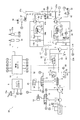
- 1 is a hydraulic circuit diagram showing an HST system mounted on a work vehicle according to an embodiment of the present invention.
- the flowchart which shows the process of brake control.
- FIG. 1 is a side view of the work vehicle 50.
- the work vehicle 50 is a wheel loader.
- the work vehicle 50 includes a vehicle body 51, a work implement 52, a plurality of tires 55, and a cab 56.
- the work machine 52 is attached to the front portion of the vehicle body 51.
- the work machine 52 includes a boom 53, a bucket 54, a lift cylinder 19, and a bucket cylinder 26.
- the boom 53 is a member for lifting the bucket 54.
- the boom 53 is driven by the lift cylinder 19.
- the bucket 54 is attached to the tip of the boom 53.
- the bucket 54 is dumped and tilted by the bucket cylinder 26.
- the cab 56 is placed on the vehicle body 51.
- FIG. 2 is a block diagram showing a configuration of the hydraulic drive mechanism 30 mounted on the work vehicle 50.
- the hydraulic drive mechanism 30 mainly includes an engine 1, a second hydraulic pump 2, a charge pump 3, a first hydraulic pump 4, a first hydraulic motor 7, a second hydraulic motor 8, an engine controller 9, a vehicle body controller 10, and a drive hydraulic circuit. 20.
- the first hydraulic pump 4 is driven by the engine 1 to discharge hydraulic oil.
- the first hydraulic motor 7 is driven by the hydraulic oil discharged from the first hydraulic pump 4.
- the second hydraulic motor 8 is driven by the hydraulic oil discharged from the first hydraulic pump 4.
- the work vehicle 50 travels as the first hydraulic motor 7 and the second hydraulic motor 8 rotate and drive the tire 55 described above.
- traveling at high speed the work vehicle 50 travels as the first hydraulic motor 7 drives the tire 55 to rotate. That is, the hydraulic drive mechanism 30 employs a so-called 1-pump 2-motor HST system.
- the engine 1 is a diesel engine, and output torque generated by the engine 1 is transmitted to the second hydraulic pump 2, the charge pump 3, the first hydraulic pump 4, and the like.
- the hydraulic drive mechanism 30 is provided with an engine rotation speed sensor 1 a that detects the actual rotation speed of the engine 1.
- the engine 1 is connected to a fuel injection device 1b.
- the engine controller 9 to be described later controls the output torque (hereinafter referred to as “engine torque”) and the rotation speed of the engine 1 by controlling the fuel injection device 1b according to the set target engine rotation speed.
- the first hydraulic pump 4 is driven by the engine 1 to discharge hydraulic oil.
- the first hydraulic pump 4 is a variable displacement hydraulic pump.
- the hydraulic oil discharged from the first hydraulic pump 4 is sent to the first hydraulic motor 7 and the second hydraulic motor 8 through the drive hydraulic circuit 20.
- the drive hydraulic circuit 20 includes a first drive circuit 20a and a second drive circuit 20b.
- the first hydraulic pump 4 is switched between a first discharge state, a second discharge state, and a neutral state.
- the first hydraulic pump 4 discharges hydraulic oil to the first drive circuit 20a in the first discharge state.
- the hydraulic oil is supplied from the first hydraulic pump 4 to the first hydraulic motor 7 and the second hydraulic motor 8 via the first drive circuit 20a, whereby the first hydraulic motor 7 and the second hydraulic motor 8 are unidirectional. (E.g., forward direction).
- the first hydraulic pump 4 discharges hydraulic oil to the second drive circuit 20b in the second discharge state.
- the hydraulic oil is supplied from the first hydraulic pump 4 to the first hydraulic motor 7 and the second hydraulic motor 8 via the second drive circuit 20b, so that the first hydraulic motor 7 and the second hydraulic motor 8 move in the other direction. It is driven (for example, in the reverse direction).
- the capacity of the first hydraulic pump 4 is the minimum capacity (for example, 0) in the neutral state.
- neutral state means a state in which the swash plate is set at a neutral position.
- the drive hydraulic circuit 20 is provided with a drive circuit pressure detector 17.
- the drive circuit pressure detector 17 is a pressure of hydraulic fluid (hereinafter referred to as “drive circuit pressure”) supplied to the first hydraulic motor 7 and the second hydraulic motor 8 via the first drive circuit 20a or the second drive circuit 20b. ) Is detected.
- the drive circuit pressure detection unit 17 includes a first drive circuit pressure sensor 17a and a second drive circuit pressure sensor 17b.
- the first drive circuit pressure sensor 17a detects the hydraulic pressure of the first drive circuit 20a.
- the second drive circuit pressure sensor 17b detects the hydraulic pressure of the second drive circuit 20b.
- the first drive circuit pressure sensor 17 a and the second drive circuit pressure sensor 17 b send detection signals to the vehicle body controller 10.
- the first hydraulic pump 4 is connected to an FR switching unit 5 and a pump capacity control cylinder 6 for controlling the discharge direction of the first hydraulic pump 4.
- the FR switching unit 5 is an electromagnetic control valve that switches the supply direction of hydraulic oil to the pump displacement control cylinder 6 based on a control signal from the vehicle body controller 10.
- the FR switching unit 5 switches the discharge direction of the first hydraulic pump 4 by switching the supply direction of the hydraulic oil to the pump displacement control cylinder 6.
- the FR switching unit 5 switches the discharge direction of the first hydraulic pump 4 between discharge to the first drive circuit 20a and discharge to the second drive circuit 20b.
- the pump displacement control cylinder 6 is driven by being supplied with hydraulic oil via the pump pilot circuit 32, and changes the tilt angle of the first hydraulic pump 4.
- a pilot pressure control unit 25 is arranged in the pump pilot circuit 32.
- the pilot pressure control unit 25 is an electromagnetic control valve that is controlled based on a control signal from the vehicle body controller 10.
- the pilot pressure control unit 25 controls the pressure of hydraulic oil supplied to the pump displacement control cylinder 6 via the pump pilot circuit 32. Specifically, the tilt angle of the first hydraulic pump 4 is adjusted by changing the hydraulic pressure in the pump displacement control cylinder 6 based on a control signal from the vehicle body controller 10.
- the pump pilot circuit 32 is connected to the charge circuit 33 and the hydraulic oil tank via a cut-off valve 47.
- the pilot port of the cutoff valve 47 is connected to the first drive circuit 20a and the second drive circuit 20b via the shuttle valve 46.
- the shuttle valve 46 introduces the larger one of the hydraulic pressure of the first drive circuit 20 a and the hydraulic pressure of the second drive circuit 20 b to the pilot port of the cutoff valve 47.
- the drive circuit pressure is applied to the pilot port of the cutoff valve 47.
- the cut-off valve 47 causes the charge circuit 33 and the pump pilot circuit 32 to communicate with each other when the drive circuit pressure is lower than a predetermined cut-off pressure. As a result, hydraulic oil is supplied from the charge circuit 33 to the pump pilot circuit 32.
- the cut-off valve 47 causes the pump pilot circuit 32 to communicate with the hydraulic oil tank and allows the hydraulic oil in the pump pilot circuit 32 to escape to the hydraulic oil tank. Thereby, when the hydraulic pressure of the pump pilot circuit 32 decreases, the capacity of the first hydraulic pump 4 is reduced, and an increase in the drive circuit pressure is suppressed.
- the charge pump 3 is a pump that is driven by the engine 1 and supplies hydraulic oil to the drive hydraulic circuit 20.
- the charge pump 3 is a fixed capacity pump.
- the charge pump 3 is connected to the charge circuit 33.
- the charge pump 3 supplies hydraulic oil to the pump pilot circuit 32 via the charge circuit 33.
- the charge circuit 33 is connected to the first drive circuit 20a via the first check valve 41.
- the first check valve 41 allows the flow of hydraulic oil from the charge circuit 33 to the first drive circuit 20a, but restricts the flow of hydraulic oil from the first drive circuit 20a to the charge circuit 33.
- the charge circuit 33 is connected to the second drive circuit 20b via the second check valve 42.
- the second check valve 42 allows the flow of hydraulic oil from the charge circuit 33 to the second drive circuit 20b, but restricts the flow of hydraulic oil from the second drive circuit 20b to the charge circuit 33.
- the charge circuit 33 is connected to the first drive circuit 20a via the first relief valve 43.
- the first relief valve 43 is opened when the hydraulic pressure of the first drive circuit 20a becomes greater than a predetermined pressure.
- the charge circuit 33 is connected to the second drive circuit 20b via the second relief valve 44.
- the second relief valve 44 is opened when the hydraulic pressure of the second drive circuit 20b becomes greater than a predetermined pressure.
- the charge circuit 33 is connected to the hydraulic oil tank via the low pressure relief valve 45.
- the low pressure relief valve 45 is opened when the hydraulic pressure of the charge circuit 33 becomes higher than a predetermined relief pressure. Thereby, the charge pressure is adjusted so as not to exceed a predetermined relief pressure.
- the second hydraulic pump 2 is driven by the engine 1.
- the hydraulic oil discharged from the second hydraulic pump 2 is supplied to the lift cylinder 19 via the working machine hydraulic circuit 31.
- the work machine 52 is driven.
- the hydraulic oil discharged from the second hydraulic pump 2 is supplied to a steering cylinder (not shown) via the working machine hydraulic circuit 31.
- the work machine hydraulic circuit 31 is provided with a work machine control valve 18.
- the work implement control valve 18 is driven according to the operation amount of the work implement operation member 23.
- the work machine control valve 18 controls the flow rate of the hydraulic oil supplied to the lift cylinder 19 according to the pilot pressure applied to the pilot port.
- the pilot pressure applied to the pilot port of the work implement control valve 18 is controlled by the pilot valve 23 a of the work implement operating member 23.
- the pilot valve 23 a applies a pilot pressure corresponding to the operation amount of the work implement operating member 23 to the pilot port of the work implement control valve 18.
- the lift cylinder 19 is controlled according to the operation amount of the work implement operation member 23.
- the bucket cylinder 26 is also controlled by a control valve in the same manner as the lift cylinder 19, but is not shown in FIG.
- the first hydraulic motor 7 is a variable displacement hydraulic motor.
- the first hydraulic motor 7 is driven by the hydraulic oil discharged from the first hydraulic pump 4 and generates a driving force for traveling.
- the first hydraulic motor 7 is provided with a first motor cylinder 11a and a first motor capacity control unit 12a.
- the first motor cylinder 11 a changes the tilt angle of the first hydraulic motor 7.
- the first motor capacity control unit 12 a is an electromagnetic control valve that is controlled based on a control signal from the vehicle body controller 10.
- the first motor capacity control unit 12 a controls the first motor cylinder 11 a based on a control signal from the vehicle body controller 10.
- the first motor cylinder 11a and the first motor capacity control unit 12a are connected to the first motor pilot circuit 34a.
- the first motor pilot circuit 34a is connected to the first drive circuit 20a via the check valve 48.
- the check valve 48 allows the flow of hydraulic oil from the first drive circuit 20a to the first motor pilot circuit 34a, but restricts the flow of hydraulic oil from the first motor pilot circuit 34a to the first drive circuit 20a.
- the first motor pilot circuit 34a is connected to the second drive circuit 20b via the check valve 49.
- the check valve 49 allows the flow of hydraulic oil from the second drive circuit 20b to the first motor pilot circuit 34a, but restricts the flow of hydraulic oil from the first motor pilot circuit 34a to the second drive circuit 20b.
- the check valves 48 and 49 supply the larger hydraulic pressure of the first drive circuit 20a and the second drive circuit 20b, that is, hydraulic fluid having a drive circuit pressure, to the first motor pilot circuit 34a.
- the first motor capacity control unit 12a switches the supply direction and the supply flow rate of hydraulic oil from the first motor pilot circuit 34a to the first motor cylinder 11a based on a control signal from the vehicle body controller 10. Thereby, the vehicle body controller 10 can arbitrarily change the capacity of the first hydraulic motor 7.
- the first drive circuit 20 a and the second drive circuit 20 b are connected to the low pressure switching valve 35.
- the low pressure switching valve 35 connects the circuit with the smaller hydraulic pressure of the first drive circuit 20 a and the second drive circuit 20 b to the hydraulic oil tank via the relief valve 36.
- the second hydraulic motor 8 is a variable displacement hydraulic motor.
- the second hydraulic motor 8 is driven by the hydraulic oil discharged from the first hydraulic pump 4 and generates a driving force for traveling.
- the second hydraulic motor 8 is provided with a second motor cylinder 11b and a second motor capacity control unit 12b.
- the second motor cylinder 11 b changes the tilt angle of the second hydraulic motor 8.
- the second motor capacity control unit 12 b is an electromagnetic control valve that is controlled based on a control signal from the vehicle body controller 10.
- the second motor capacity control unit 12 b controls the second motor cylinder 11 b based on a control signal from the vehicle body controller 10.
- the second motor cylinder 11b and the second motor capacity control unit 12b are connected to the second motor pilot circuit 34b.
- the second motor pilot circuit 34b is connected to the first drive circuit 20a and the second drive circuit 20b via the shuttle valve 22.
- the shuttle valve 22 connects the circuit having the larger hydraulic pressure of the first drive circuit 20a and the second drive circuit 20b to the second motor pilot circuit 34b.
- the shuttle valve 22 supplies the larger hydraulic pressure of the first drive circuit 20a and the second drive circuit 20b, that is, hydraulic fluid having a drive circuit pressure, to the second motor pilot circuit 34b.
- the second motor capacity control unit 12b switches the supply direction and the supply flow rate of hydraulic oil from the second motor pilot circuit 34b to the second motor cylinder 11b. Thereby, the vehicle body controller 10 can arbitrarily change the capacity of the second hydraulic motor 8.
- the output shaft 7a of the first hydraulic motor 7 is connected to the drive shaft 28 via the first reduction mechanism 27a.
- the output shaft 8 a of the second hydraulic motor 8 is connected to the drive shaft 28 via the second reduction mechanism 27 b and the clutch 37.
- the drive shaft 28 is connected to the tire 55 described above.
- the clutch 37 is switched between an engaged state and a released state.
- the clutch 37 connects the second hydraulic motor 8 and the drive shaft 28 in the engaged state. Therefore, when the clutch 37 is in the engaged state, the driving force from the first hydraulic motor 7 and the driving force from the second hydraulic motor 8 are transmitted to the drive shaft 28. Thereby, the tire 55 is rotationally driven.
- the clutch 37 disconnects the second hydraulic motor 8 and the drive shaft 28 in the released state. Therefore, when the clutch 37 is in the released state, only the driving force from the first hydraulic motor 7 out of the first hydraulic motor 7 and the second hydraulic motor 8 is transmitted to the drive shaft 28. Thereby, the tire 55 is rotationally driven.
- the hydraulic drive mechanism 30 has a clutch control unit 38 for controlling the switching of the clutch 37.
- the clutch control unit 38 is an electromagnetic control valve that is controlled based on a control signal from the vehicle body controller 10.
- the vehicle body controller 10 switches the clutch 37 between the engaged state and the released state by controlling the clutch control unit 38.
- the clutch control unit 38 switches between supply and discharge of hydraulic fluid from the pilot hydraulic power source 39 to the clutch 37 based on a control signal from the vehicle body controller 10. As a result, the clutch 37 is switched between the engaged state and the released state.
- the hydraulic drive mechanism 30 includes a parking brake 61 and a parking brake control unit 62.
- the parking brake 61 is switched between a braking state and a non-braking state.
- the parking brake 61 brakes the drive shaft 28 in the braking state.
- the parking brake 61 releases the drive shaft 28 in the non-braking state.
- the parking brake control unit 62 is an electromagnetic control valve that is controlled based on a control signal from the vehicle body controller 10.
- the vehicle body controller 10 switches the parking brake 61 between a braking state and a non-braking state by controlling the parking brake control unit 62.
- the parking brake 61 is switched between a braking state and a non-braking state according to an operation of a parking brake operation member 15 described later.
- the parking brake control unit 62 can release the operation command from the parking brake operation member 15 based on the control signal from the vehicle body controller 10. For example, even if the parking brake operation member 15 is operated, the parking brake control unit 62 can maintain the parking brake 61 in the non-braking state based on the control signal from the vehicle body controller 10. Further, the parking brake control unit 62 can switch the parking brake 61 to the braking state by stopping the release of the operation command from the parking brake operation member 15 based on the control signal from the vehicle body controller 10. Thereby, the parking brake 61 is switched between a braking state and a non-braking state. For example, the parking brake 61 has a brake disc portion 61a and a piston portion 61b.
- the piston part 61b brings the brake disks of the brake disk part 61a into contact with each other by hydraulic pressure. As a result, the parking brake 61 enters the braking state. Further, when the hydraulic oil is discharged from the piston part 61b, the brake disks are held in a non-contact state by the elastic force of the elastic member provided in the piston part 61b. Thereby, the parking brake 61 will be in a non-braking state.
- the hydraulic drive mechanism 30 is provided with a vehicle speed detector 16.
- the vehicle speed detection unit 16 is a sensor that detects the vehicle speed.
- the vehicle speed detection unit 16 sends a vehicle speed signal to the vehicle body controller 10.
- the vehicle speed detection unit 16 detects the vehicle speed, for example, by detecting the rotational speed of the drive shaft 28.
- the work vehicle 50 includes an accelerator operation member 13a, a forward / reverse switching operation member 14, and a parking brake operation member 15.
- the accelerator operation member 13a is a member for the operator to set the target rotation speed of the engine 1.
- the accelerator operation member 13a is an accelerator pedal, for example, and is operated by an operator.
- the accelerator operation member 13 a is connected to the accelerator operation amount sensor 13.
- the accelerator operation amount sensor 13 is composed of a potentiometer or the like.
- the accelerator operation amount sensor 13 sends an opening degree signal indicating the operation amount of the accelerator operation member 13 a (hereinafter referred to as “accelerator operation amount”) to the engine controller 9.
- the operator can control the rotational speed of the engine 1 by adjusting the accelerator operation amount.
- the forward / reverse switching operation member 14 is operated by an operator to be switched between a forward position, a reverse position, and a neutral position.
- the forward / reverse switching operation member 14 sends an operation signal indicating the position of the forward / reverse switching operation member 14 to the vehicle body controller 10.
- the operator can switch between forward and reverse travel of the work vehicle 50 by operating the forward / reverse switching operation member 14.
- the parking brake operating member 15 is operated to operate the parking brake 61.
- the parking brake operation member 15 is a parking switch or a parking lever, for example, and is operated by an operator. When the parking brake operation member 15 is operated, an operation signal is sent to the vehicle body controller 10.
- the engine controller 9 is an electronic control unit having an arithmetic device such as a CPU and various memories.
- the engine controller 9 controls the engine 1 so that the target rotation speed set by the accelerator operation member 13a is obtained.
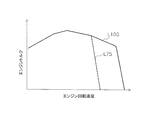
- FIG. 3 shows an output torque line of the engine 1.
- the output torque line of the engine 1 shows the relationship between the rotational speed of the engine 1 and the maximum engine torque that can be output by the engine 1 at each rotational speed.
- a solid line L100 indicates an engine output torque line when the accelerator operation amount is 100%. This engine output torque line corresponds to, for example, the rating of the engine 1 or the maximum power output.
- the accelerator operation amount of 100% means that the accelerator operation member 13a is operated to the maximum.
- a broken line L75 indicates an engine output torque line when the accelerator operation amount is 75%.
- the engine controller 9 controls the output of the engine 1 so that the engine torque is equal to or less than the engine output torque line.
- the control of the output of the engine 1 is performed, for example, by controlling the upper limit value of the fuel
- the vehicle body controller 10 is an electronic control unit having an arithmetic device such as a CPU and various memories.
- the vehicle body controller 10 corresponds to a control unit of the present invention.
- the vehicle body controller 10 controls the capacity of the first hydraulic pump 4 and the capacity of the first hydraulic motor 7 by electronically controlling each control valve based on the output signal from each detection unit.
- the vehicle body controller 10 outputs a command signal to the pilot pressure control unit 25 based on the engine rotation speed detected by the engine rotation speed sensor 1a. This defines the relationship between the pump capacity and the drive circuit pressure.
- FIG. 4 shows an example of pump capacity-drive circuit pressure characteristics.
- the pump capacity-drive circuit pressure characteristic indicates the relationship between the pump capacity and the drive circuit pressure.
- L11 to L16 in the figure are lines showing the pump displacement-drive circuit pressure characteristics that are changed according to the engine speed.
- the vehicle body controller 10 controls the flow rate of the pilot pressure control unit 25 based on the engine speed, whereby the pump displacement-drive circuit pressure characteristic is changed to L11 to L16. As a result, the pump capacity is controlled to correspond to the engine speed and the drive circuit pressure.
- the pump displacement-drive circuit pressure characteristic changes from L11 to L16 as the engine speed increases.
- the pump capacity-drive circuit pressure characteristic is set so that the pump capacity is reduced when the drive circuit pressure is increased and the pump capacity is increased when the drive circuit pressure is decreased.
- the cut-off valve 47 is activated so that the drive circuit pressure is constant at the aforementioned cut-off pressure value Px. It has become.
- the upper limit of the drive circuit pressure is constant at the above-described cut-off pressure value Px.
- the vehicle body controller 10 sets the clutch 37 described above to the engaged state when the vehicle speed is smaller than a predetermined switching speed.
- the output shaft 7a of the first hydraulic motor 7 is connected to the drive shaft 28 via the first reduction mechanism 27a.
- the output shaft 8a of the second hydraulic motor 8 is connected to the drive shaft 28 via the second reduction mechanism 27b.
- the traveling state at this time is referred to as “two-motor traveling state”.
- the vehicle body controller 10 sets the clutch 37 to the released state when the vehicle speed is equal to or higher than a predetermined switching speed.
- the traveling state at this time is referred to as “one motor traveling state”). Called). Accordingly, the work vehicle 50 travels in the two-motor traveling state when the vehicle speed is traveling at a lower speed than the predetermined switching speed. In addition, when the vehicle speed is higher than a predetermined switching speed, the work vehicle 50 travels in a one-motor traveling state.
- the vehicle body controller 10 processes output signals from the engine rotation speed sensor 1a and the drive circuit pressure detection unit 17, and outputs a motor capacity command signal to the first motor capacity control unit 12a.
- the vehicle body controller 10 sets the motor capacity from the value of the engine speed and the value of the drive circuit pressure with reference to the motor capacity-drive circuit pressure characteristic stored in the vehicle body controller 10.
- the vehicle body controller 10 outputs a tilt angle change command corresponding to the set motor capacity to the first motor capacity controller 12a.
- FIG. 5 shows an example of motor capacity-drive circuit pressure characteristics.
- a solid line L21 in the figure is a line that defines the motor capacity with respect to the drive circuit pressure in a state where the engine speed is a certain value.
- the motor capacity here corresponds to the tilt angle of the first hydraulic motor 7. Until the drive circuit pressure is below a certain value, the tilt angle is minimum (Min). Thereafter, as the drive circuit pressure increases, the tilt angle gradually increases (inclined portion L22 indicated by a solid line). After the tilt angle reaches the maximum (Max), the tilt angle maintains the maximum tilt angle Max even if the drive circuit pressure increases.
- the inclined portion L22 defines the target pressure of the drive circuit pressure. That is, the vehicle body controller 10 increases the capacity of the first hydraulic motor 7 when the drive circuit pressure becomes larger than the target pressure.
- the target pressure is determined according to the engine speed. That is, the inclined portion L22 shown in FIG. Specifically, when the engine speed is low, the inclined portion L22 is controlled so that the tilt angle increases from a state where the drive circuit pressure is lower, and reaches the maximum tilt angle when the drive circuit pressure is lower. (Refer to the inclined portion L23 of the lower broken line in FIG. 5). On the contrary, if the engine speed is high, the minimum tilt angle Min is maintained until the drive circuit pressure becomes higher, and control is performed so as to reach the maximum tilt angle Max in a state where the drive circuit pressure is higher (in FIG. 5). (Refer to the upper inclined portion L24). Thereby, the traction force and the vehicle speed of the work vehicle can be changed steplessly, and can be automatically shifted from the vehicle speed of zero to the maximum speed without a shift operation.
- the vehicle body controller 10 can arbitrarily set the upper limit capacity and the lower limit capacity within a range between the maximum capacity Max and the minimum capacity Min of the first hydraulic motor 7.
- the upper limit capacity is set as the upper limit value of the capacity of the first hydraulic motor 7.
- the lower limit capacity is set as the lower limit value of the capacity of the first hydraulic motor 7.
- the capacity of the first hydraulic motor 7 is limited to a value not more than the upper limit capacity Ma, which is smaller than the maximum capacity Max.
- the maximum traction force can be reduced compared to when the upper limit capacity is not set. Further, in FIG.
- the vehicle body controller 10 outputs a motor capacity command signal set in the same manner as described above to the second motor capacity control unit 12b.
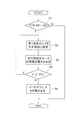
- FIG. 6 is a flowchart showing processing in brake control.
- step S1 it is determined whether or not the parking brake operation member 15 (P / B SW) has been operated.
- the parking brake operating member 15 has been operated means an operation for setting the parking brake 61 to the braking state.
- the vehicle body controller 10 sets the first hydraulic pump 4 to a neutral state in step S2. Thereby, the capacity of the first hydraulic pump 4 becomes the minimum capacity.
- step S3 the vehicle body controller 10 increases the capacity of the first hydraulic motor 7.
- the oblique axis is operated in a direction in which the capacity of the first hydraulic motor 7 increases.
- the work vehicle 50 is decelerated by increasing the resistance force in the first hydraulic motor 7.
- the vehicle body controller 10 controls the flow rate of hydraulic oil supplied to the pump displacement control cylinder 6 by the pilot pressure control unit 25, thereby reducing the lower limit capacity of the first hydraulic motor 7 to the parking brake operation member 15. Is gradually increased from the capacity of the first hydraulic motor 7 to the maximum capacity at the time when is operated. Thereby, the vehicle body controller 10 reduces the vehicle speed.
- FIG. 7 shows the change speed of the capacity of the first hydraulic motor 7.
- FIG. 7A shows the speed of changing the capacity of the first hydraulic motor 7 when the capacity of the first hydraulic motor 7 is increased in the brake control (hereinafter referred to as “increase speed”).
- the increasing speed is defined by time ⁇ T1 when the capacity of the first hydraulic motor 7 changes from 0% to 100%.
- the vehicle body controller 10 sets the capacity Qp of the first hydraulic motor 7 at the time when the parking brake operation member 15 is operated as the lower limit capacity of the first hydraulic motor 7, and then sets the lower limit capacity of the first hydraulic motor 7 to Qp.
- the maximum capacity (100%) is gradually increased at the increase rate described above.
- FIG. 7A shows the speed of changing the capacity of the first hydraulic motor 7 when the capacity of the first hydraulic motor 7 is increased in the brake control (hereinafter referred to as “increase speed”).
- the increasing speed is defined by time ⁇ T1 when the capacity of the first hydraulic motor 7 changes from 0% to 100%.
- the vehicle body controller 10 sets the capacity
- the reduction speed is defined by a time ⁇ T2 when the capacity of the first hydraulic motor 7 changes from 0% to 100%.
- the body controller 10 returns the capacity of the first hydraulic motor 7 to the lower limit capacity in the normal state when the parking brake 61 is released.
- the vehicle body controller 10 sets the capacity Qp ′ of the first hydraulic motor 7 at the time when the release operation of the parking brake 61 is executed as the lower limit capacity of the first hydraulic motor 7.
- the lower limit capacity is gradually reduced from Qp ′ to the lower limit capacity in the normal state at the reduction rate described above.
- the normal state means a state where brake control is not performed.
- the reduction rate is preferably the same as the increase rate or greater than the increase rate.
- step S4 it is determined whether or not the vehicle speed V is equal to or higher than a predetermined threshold value Vth.
- the process returns to step S2. That is, when the vehicle speed V is equal to or higher than the predetermined threshold value Vth, the work vehicle 50 is decelerated by increasing the capacity of the first hydraulic motor 7 without operating the parking brake 61.
- step S4 when the vehicle speed V becomes smaller than the predetermined threshold value Vth, the process proceeds to step S5.
- step S ⁇ b> 5 the vehicle body controller 10 operates the parking brake 61.
- the predetermined threshold value Vth is a value larger than zero.
- the predetermined threshold Vth is preferably substantially the same value as the switching speed described above. Accordingly, the vehicle body controller 10 operates the parking brake 61 when the clutch 37 is switched to the engaged state. That is, the vehicle body controller 10 operates the parking brake 61 when switching from the one-motor running state to the two-motor running state during execution of the brake control.
- braking by the parking brake 61 and braking by the resistance force of the first hydraulic motor 7 may be used in combination.
- braking by the parking brake 61 is performed, and braking by the resistance force in the first hydraulic motor 7 may be stopped.
- the parking brake 61 is not activated and the capacity of the first hydraulic pump 4 is not activated when the vehicle speed is equal to or higher than the predetermined threshold. Is reduced and the capacity of the first hydraulic motor 7 is increased. Thereby, the vehicle speed can be gradually reduced by the resistance force of the first hydraulic motor 7.
- the parking brake 61 is activated when the vehicle speed becomes lower than a predetermined threshold. As a result, the vehicle speed further decreases and the work vehicle 50 stops. Thereby, the work vehicle 50 can be stopped while suppressing the occurrence of shock.
- the capacity of the first hydraulic motor 7 is gradually increased at the increasing speed shown in FIG. For this reason, it is suppressed that the capacity
- the wheel loader has been described as an example of the work vehicle 50 to which the present invention is applied.
- the present invention is not limited to this.
- the present invention can be applied to other work vehicles equipped with an HST such as a bulldozer or a backhoe loader.
- the work vehicle 50 equipped with the so-called 1-pump 2-motor HST system in which two hydraulic motors are driven by hydraulic oil from one hydraulic pump has been described as an example.
- the present invention is not limited to this.
- the present invention may be applied to a work vehicle equipped with a so-called 1-pump 1-motor HST system in which one hydraulic motor is driven by hydraulic oil from one first hydraulic pump 4.
- the present invention it is possible to provide a work vehicle and a work vehicle control method capable of decelerating the vehicle while suppressing the occurrence of shock when the parking brake is operated while the vehicle is running.
Landscapes
- Engineering & Computer Science (AREA)
- Mechanical Engineering (AREA)
- Transportation (AREA)
- General Engineering & Computer Science (AREA)
- Chemical & Material Sciences (AREA)
- Combustion & Propulsion (AREA)
- Control Of Fluid Gearings (AREA)
- Regulating Braking Force (AREA)
- Operation Control Of Excavators (AREA)
- Control Of Driving Devices And Active Controlling Of Vehicle (AREA)
Description
本発明は、作業車両及び作業車両の制御方法に関する。
一般的に、ホイールローダ等の作業車両には、いわゆるHST(HydroStatic Transmission)を搭載しているものがある。HST式の作業車両は、エンジンによって油圧ポンプを駆動し、油圧ポンプから吐出された作動油によって走行用油圧モータを駆動する。これにより、作業車両が走行する。このようなHST式の作業車両では、エンジン回転速度、油圧ポンプの容量、走行用油圧モータの容量などを制御することによって、車速および牽引力を制御することができる(特許文献1参照)。
また、作業車両は、パーキングブレーキを備えている。パーキングブレーキは、オペレータがパーキングスイッチなどのパーキングブレーキ操作部材を操作することにより作動する。通常、オペレータは、フットブレーキなどによって作業車両を減速させ、作業車両が停止した状態でパーキングブレーキを作動させる。これにより、作業車両が停止位置から移動しないようにされる。
上述したように、パーキングブレーキは、通常、作業車両が停止した状態で作動される。しかし、作業車両の走行中に、オペレータが誤って、或いは意図的に、パーキングブレーキ操作部材を操作することがある。この場合、作業車両が急激に減速することにより、ショックが発生する恐れがある。
本発明の課題は、車両の走行中にパーキングブレーキの操作が行われたときに、ショックの発生を抑えながら車両を減速させることができる作業車両および作業車両の制御方法を提供することにある。
本発明の第1の態様に係る作業車両は、エンジンと、油圧ポンプと、走行用油圧モータと、車速検出部と、パーキングブレーキと、パーキングブレーキ操作部材と、制御部とを備える。油圧ポンプは、エンジンによって駆動される。第1油圧モータは、油圧ポンプから吐出された作動油によって駆動される。車速検出部は、車速を検出する。パーキングブレーキ操作部材は、パーキングブレーキを作動させるために操作される。制御部は、ブレーキ制御を実行する。制御部は、ブレーキ制御において、パーキングブレーキ操作部材が操作されると車速が所定の閾値以上であるか否かを判定する。制御部は、車両が走行している状態で車速が所定の閾値以上であるときには、パーキングブレーキを作動させずに油圧ポンプの容量を低減させると共に第1油圧モータの容量を増大させる。そして、制御部は、車速が所定の閾値より小さくなったときにパーキングブレーキを作動させる。
本発明の第2の態様に係る作業車両は、第1の態様の作業車両であって、制御部は、ブレーキ制御において、第1油圧モータの容量の下限値を、パーキングブレーキ操作部材が操作された時点での第1油圧モータの容量から最大容量まで徐々に増大させることにより、車速を低減させる。
本発明の第3の態様に係る作業車両は、第1又は第2の態様の作業車両であって、駆動軸と、第2油圧モータと、クラッチとをさらに備える。第1油圧モータからの駆動力が駆動軸に伝達される。第2油圧モータは、油圧ポンプから吐出された作動油によって駆動される。クラッチは、係合状態と解放状態とに切り換えられる。クラッチは、係合状態において、第2油圧モータと駆動軸とを連結する。クラッチは、解放状態において、第2油圧モータと駆動軸とを非連結とする。制御部は、車速が所定の切替速度以上であるときにはクラッチを解放状態に設定する。制御部は、車速が所定の切替速度より小さいであるときにはクラッチを係合状態に設定する。制御部は、ブレーキ制御において、クラッチを係合状態に切り替えたときにパーキングブレーキを作動させる。
本発明の第4の態様に係る作業車両の制御方法は、エンジンと、油圧ポンプと、第1油圧モータと、車速検出部と、パーキングブレーキと、パーキングブレーキ操作部材とを備える作業車両の制御方法である。油圧ポンプは、エンジンによって駆動される。第1油圧モータは、油圧ポンプから吐出された作動油によって駆動される。車速検出部は、車速を検出する。パーキングブレーキ操作部材は、パーキングブレーキを作動させるために操作される。当該制御方法は、次のステップを備える。第1ステップは、パーキングブレーキ操作部材が操作されると車速が所定の閾値以上であるか否かを判定することである。第2ステップは、車両が走行している状態で車速が所定の閾値以上であるときには、パーキングブレーキを作動させずに油圧ポンプの容量を低減すると共に第1油圧モータの容量を増大することである。第3ステップは、車速が所定の閾値より小さくなったときにパーキングブレーキを作動させることである。
本発明の第5の態様に係る作業車両の制御方法は、エンジンと、エンジンによって駆動される油圧ポンプと、油圧ポンプから吐出された作動油によって駆動される第1油圧モータと、車速を検出する車速検出部と、パーキングブレーキと、パーキングブレーキを作動させるために操作されるパーキングブレーキ操作部材とを備える作業車両の制御方法である。この作業車両の制御方法では、パーキングブレーキ操作部材が操作されると車速が所定の閾値以上であるか否かを判定し、車両が走行している状態で車速が所定の閾値以上であるときには、パーキングブレーキを作動させずに第1油圧モータの抵抗力を増大させることで車速を徐々に低下させ、車速が所定の閾値より小さくなったときにパーキングブレーキを作動させる。
本発明の第1の態様に係る作業車両では、パーキングブレーキ操作部材が操作されても、車速が所定の閾値以上であるときには、パーキングブレーキが作動されずに、油圧ポンプの容量が低減されると共に第1油圧モータの容量を増大される。第1油圧モータの容量が増大すると、第1油圧モータの抵抗力が増大する。これにより、車速を徐々に低下させることができる。そして、車速が所定の閾値より小さくなったときにパーキングブレーキが作動される。これにより、ショックの発生を抑えながら車両をさらに減速させることができる。
本発明の第2の態様に係る作業車両では、第1油圧モータの容量が急激に変化することが抑えられる。これにより、ショックの発生をさらに抑えながら、減速することができる。
本発明の第3の態様に係る作業車両では、車速が所定の切替速度より小さいときにクラッチが係合状態とされることにより、第1油圧モータと第2油圧モータとの両方からの駆動力によって作業車両が走行する。これにより、低速走行時に高い駆動トルクを得ることができる。また、車速が所定の切替速度以上であるときにクラッチが解放状態とされることにより、第1油圧モータからの駆動力によって作業車両が走行する。これにより、高速走行時の燃費を向上させることができる。また、車速が低下して所定の切替速度に達したときにパーキングブレーキが作動するが、所定の切替速度以下の車速では第2油圧モータが駆動される。このため、ショックを少なく減速することができる。また、油圧ポンプや油圧配管などの機器への負荷を低減することができる。
本発明の第4の態様に係る作業車両の制御方法では、パーキングブレーキ操作部材が操作されても、車速が所定の閾値以上であるときには、パーキングブレーキが作動されずに、油圧ポンプの容量が低減されると共に第1油圧モータの容量を増大される。第1油圧モータの容量が増大すると、第1油圧モータの抵抗力が増大する。これにより、車速を徐々に低下させることができる。そして、車速が所定の閾値より小さくなったときにパーキングブレーキが作動される。これにより、ショックの発生を抑えながら車両をさらに減速させることができる。
本発明の第5の態様に係る作業車両の制御方法では、パーキングブレーキ操作部材が操作されても、車速が所定の閾値以上であるときには、パーキングブレーキが作動されずに、第1油圧モータの抵抗力を増大させることで車速を徐々に低下させる。そして、車速が所定の閾値より小さくなったときにパーキングブレーキが作動される。これにより、ショックの発生を抑えながら車両をさらに減速させることができる。
以下、本発明の一実施形態に係る作業車両50について、図面を用いて説明する。図1は、作業車両50の側面図である。作業車両50は、ホイールローダである。作業車両50は、車体51と、作業機52と、複数のタイヤ55と、キャブ56と、を備えている。作業機52は、車体51の前部に装着されている。作業機52は、ブーム53とバケット54とリフトシリンダ19とバケットシリンダ26とを有する。ブーム53は、バケット54を持ち上げるための部材である。ブーム53は、リフトシリンダ19によって駆動される。バケット54は、ブーム53の先端に取り付けられている。バケット54は、バケットシリンダ26によってダンプおよびチルトされる。キャブ56は、車体51上に載置されている。
図2は、作業車両50に搭載された油圧駆動機構30の構成を示すブロック図である。油圧駆動機構30は、主として、エンジン1、第2油圧ポンプ2、チャージポンプ3、第1油圧ポンプ4、第1油圧モータ7、第2油圧モータ8、エンジンコントローラ9、車体コントローラ10、駆動油圧回路20を有している。油圧駆動機構30では、第1油圧ポンプ4がエンジン1によって駆動されることにより作動油を吐出する。第1油圧モータ7が、第1油圧ポンプ4から吐出された作動油によって駆動される。また、第2油圧モータ8が、第1油圧ポンプ4から吐出された作動油によって駆動される。そして、低速走行時には、第1油圧モータ7と第2油圧モータ8とが上述したタイヤ55を回転駆動することにより、作業車両50が走行する。高速走行時には、第1油圧モータ7がタイヤ55を回転駆動することにより、作業車両50が走行する。すなわち、油圧駆動機構30では、いわゆる1ポンプ2モータのHSTシステムが採用されている。
エンジン1は、ディーゼル式のエンジンであり、エンジン1で発生した出力トルクが、第2油圧ポンプ2、チャージポンプ3、第1油圧ポンプ4等に伝達される。油圧駆動機構30には、エンジン1の実回転速度を検出するエンジン回転速度センサ1aが設けられている。また、エンジン1には、燃料噴射装置1bが接続されている。後述するエンジンコントローラ9は、設定された目標エンジン回転速度に応じて燃料噴射装置1bを制御することにより、エンジン1の出力トルク(以下、「エンジントルク」と呼ぶ)と回転速度とを制御する。
第1油圧ポンプ4は、エンジン1によって駆動されることにより作動油を吐出する。第1油圧ポンプ4は、可変容量型の油圧ポンプである。第1油圧ポンプ4から吐出された作動油は、駆動油圧回路20を通って第1油圧モータ7及び第2油圧モータ8へと送られる。具体的には、駆動油圧回路20は、第1駆動回路20aと第2駆動回路20bとを有する。第1油圧ポンプ4は、第1吐出状態と第2吐出状態と中立状態とに切り換えられる。第1油圧ポンプ4は、第1吐出状態において、第1駆動回路20aに作動油を吐出する。作動油が、第1油圧ポンプ4から第1駆動回路20aを介して第1油圧モータ7及び第2油圧モータ8に供給されることにより、第1油圧モータ7及び第2油圧モータ8が一方向(例えば、前進方向)に駆動される。第1油圧ポンプ4は、第2吐出状態において、第2駆動回路20bに作動油を吐出する。作動油が、第1油圧ポンプ4から第2駆動回路20bを介して第1油圧モータ7及び第2油圧モータ8に供給されることにより、第1油圧モータ7及び第2油圧モータ8が他方向(例えば、後進方向)に駆動される。第1油圧ポンプ4の容量は、中立状態において、最小容量(例えば0)となる。例えば、第1油圧ポンプ4が、斜板を有する油圧ポンプである場合には、「中立状態」とは、斜板が中立位置に設定された状態を意味する。
駆動油圧回路20には、駆動回路圧検出部17が設けられている。駆動回路圧検出部17は、第1駆動回路20a又は第2駆動回路20bを介して第1油圧モータ7と第2油圧モータ8とに供給される作動油の圧力(以下、「駆動回路圧」)を検出する。具体的には、駆動回路圧検出部17は、第1駆動回路圧センサ17aと第2駆動回路圧センサ17bとを有する。第1駆動回路圧センサ17aは、第1駆動回路20aの油圧を検出する。第2駆動回路圧センサ17bは、第2駆動回路20bの油圧を検出する。第1駆動回路圧センサ17aと第2駆動回路圧センサ17bとは、検出信号を車体コントローラ10に送る。また、第1油圧ポンプ4には、第1油圧ポンプ4の吐出方向を制御するためのFR切換部5とポンプ容量制御シリンダ6とが接続されている。
FR切換部5は、車体コントローラ10からの制御信号に基づいてポンプ容量制御シリンダ6への作動油の供給方向を切り換える電磁制御弁である。FR切換部5は、ポンプ容量制御シリンダ6への作動油の供給方向を切り換えることにより、第1油圧ポンプ4の吐出方向を切り換える。具体的には、FR切換部5は、第1駆動回路20aへの吐出と第2駆動回路20bへの吐出とに第1油圧ポンプ4の吐出方向を切り換える。ポンプ容量制御シリンダ6は、ポンプパイロット回路32を介して作動油を供給されることにより駆動され、第1油圧ポンプ4の傾転角を変更する。
ポンプパイロット回路32には、パイロット圧制御部25が配置されている。パイロット圧制御部25は、車体コントローラ10からの制御信号に基づいて制御される電磁制御弁である。パイロット圧制御部25は、ポンプパイロット回路32を介してポンプ容量制御シリンダ6に供給される作動油の圧力を制御する。具体的には、車体コントローラ10からの制御信号に基づいて、ポンプ容量制御シリンダ6内の油圧を変更することで、第1油圧ポンプ4の傾転角を調整する。
ポンプパイロット回路32は、カットオフ弁47を介してチャージ回路33と作動油タンクとに接続されている。カットオフ弁47のパイロットポートは、シャトル弁46を介して第1駆動回路20aと第2駆動回路20bとに接続されている。シャトル弁46は、第1駆動回路20aの油圧と第2駆動回路20bの油圧とのうち大きい方をカットオフ弁47のパイロットポートに導入する。これにより、カットオフ弁47のパイロットポートには駆動回路圧が印加される。カットオフ弁47は、駆動回路圧が所定のカットオフ圧より低いときには、チャージ回路33とポンプパイロット回路32とを連通させる。これにより、作動油がチャージ回路33からポンプパイロット回路32に供給される。カットオフ弁47は、駆動回路圧が所定のカットオフ圧以上になると、ポンプパイロット回路32を作動油タンクに連通させて、ポンプパイロット回路32の作動油を作動油タンクに逃がす。これにより、ポンプパイロット回路32の油圧が低下することにより、第1油圧ポンプ4の容量が低減され、駆動回路圧の上昇が抑えられる。
チャージポンプ3は、エンジン1によって駆動され、駆動油圧回路20へと作動油を供給するためのポンプである。チャージポンプ3は、固定容量ポンプである。チャージポンプ3は、チャージ回路33に接続されている。チャージポンプ3は、チャージ回路33を介してポンプパイロット回路32に作動油を供給する。チャージ回路33は、第1チェック弁41を介して第1駆動回路20aに接続されている。第1チェック弁41は、チャージ回路33から第1駆動回路20aへの作動油の流れを許容するが、第1駆動回路20aからチャージ回路33への作動油の流れを規制する。また、チャージ回路33は、第2チェック弁42を介して第2駆動回路20bに接続されている。第2チェック弁42は、チャージ回路33から第2駆動回路20bへの作動油の流れを許容するが、第2駆動回路20bからチャージ回路33への作動油の流れを規制する。また、チャージ回路33は、第1リリーフ弁43を介して第1駆動回路20aに接続されている。第1リリーフ弁43は、第1駆動回路20aの油圧が所定の圧力より大きくなったときに開かれる。チャージ回路33は、第2リリーフ弁44を介して第2駆動回路20bに接続されている。第2リリーフ弁44は、第2駆動回路20bの油圧が所定の圧力より大きくなったときに開かれる。また、チャージ回路33は、低圧リリーフ弁45を介して作動油タンクに接続されている。低圧リリーフ弁45は、チャージ回路33の油圧が所定のリリーフ圧より大きくなったときに開かれる。これにより、チャージ圧が所定のリリーフ圧を越えないように調整される。
第2油圧ポンプ2は、エンジン1によって駆動される。第2油圧ポンプ2から吐出された作動油は、作業機用油圧回路31を介してリフトシリンダ19に供給される。これにより、作業機52が駆動される。また、第2油圧ポンプ2から吐出された作動油は、作業機用油圧回路31を介してステアリングシリンダ(図示せず)に供給される。これにより、作業車両50の向きが変更される。作業機用油圧回路31には、作業機制御弁18が設けられている。作業機制御弁18は、作業機操作部材23の操作量に応じて駆動される。作業機制御弁18は、パイロットポートに印加されるパイロット圧に応じて、リフトシリンダ19に供給される作動油の流量を制御する。作業機制御弁18のパイロットポートに印加されるパイロット圧は、作業機操作部材23のパイロット弁23aによって制御される。パイロット弁23aは、作業機操作部材23の操作量に応じたパイロット圧を作業機制御弁18のパイロットポートに印加する。これにより、作業機操作部材23の操作量に応じてリフトシリンダ19が制御される。なお、バケットシリンダ26も、リフトシリンダ19と同様に、制御弁によって制御されるが、図2においては図示を省略している。
第1油圧モータ7は、可変容量型の油圧モータである。第1油圧モータ7は、第1油圧ポンプ4から吐出された作動油によって駆動され、走行のための駆動力を生じさせる。第1油圧モータ7には、第1モータシリンダ11aと、第1モータ容量制御部12aとが設けられている。第1モータシリンダ11aは、第1油圧モータ7の傾転角を変更する。第1モータ容量制御部12aは、車体コントローラ10からの制御信号に基づいて制御される電磁制御弁である。第1モータ容量制御部12aは、車体コントローラ10からの制御信号に基づいて第1モータシリンダ11aを制御する。第1モータシリンダ11aと第1モータ容量制御部12aとは、第1モータパイロット回路34aに接続されている。第1モータパイロット回路34aは、チェック弁48を介して第1駆動回路20aに接続されている。チェック弁48は、第1駆動回路20aから第1モータパイロット回路34aへの作動油の流れを許容するが、第1モータパイロット回路34aから第1駆動回路20aへの作動油の流れを規制する。第1モータパイロット回路34aは、チェック弁49を介して第2駆動回路20bに接続されている。チェック弁49は、第2駆動回路20bから第1モータパイロット回路34aへの作動油の流れを許容するが、第1モータパイロット回路34aから第2駆動回路20bへの作動油の流れを規制する。チェック弁48,49により、第1駆動回路20aと第2駆動回路20bとのうち大きい方の油圧、すなわち駆動回路圧の作動油が、第1モータパイロット回路34aに供給される。第1モータ容量制御部12aは、車体コントローラ10からの制御信号に基づいて、第1モータパイロット回路34aから第1モータシリンダ11aへの作動油の供給方向および供給流量を切り換える。これにより、車体コントローラ10は、第1油圧モータ7の容量を任意に変えることができる。
第1駆動回路20aと第2駆動回路20bとは、低圧切換弁35に接続されている。低圧切換弁35は、第1駆動回路20aと第2駆動回路20bとのうち油圧の小さい方の回路をリリーフ弁36を介して作動油タンクに接続する。
第2油圧モータ8は、可変容量型の油圧モータである。第2油圧モータ8は、第1油圧ポンプ4から吐出された作動油によって駆動され、走行のための駆動力を生じさせる。第2油圧モータ8には、第2モータシリンダ11bと、第2モータ容量制御部12bとが設けられている。第2モータシリンダ11bは、第2油圧モータ8の傾転角を変更する。第2モータ容量制御部12bは、車体コントローラ10からの制御信号に基づいて制御される電磁制御弁である。第2モータ容量制御部12bは、車体コントローラ10からの制御信号に基づいて第2モータシリンダ11bを制御する。第2モータシリンダ11bと第2モータ容量制御部12bとは、第2モータパイロット回路34bに接続されている。第2モータパイロット回路34bは、シャトル弁22を介して第1駆動回路20aと第2駆動回路20bに接続されている。シャトル弁22は、第1駆動回路20aと第2駆動回路20bとのうち油圧の大きい方の回路を第2モータパイロット回路34bに接続する。シャトル弁22によって、第1駆動回路20aと第2駆動回路20bとのうち大きい方の油圧、すなわち駆動回路圧の作動油が、第2モータパイロット回路34bに供給される。第2モータ容量制御部12bは、車体コントローラ10からの制御信号に基づいて、第2モータパイロット回路34bから第2モータシリンダ11bへの作動油の供給方向および供給流量を切り換える。これにより、車体コントローラ10は、第2油圧モータ8の容量を任意に変えることができる。
第1油圧モータ7の出力軸7aは、第1減速機構27aを介して駆動軸28に接続されている。第2油圧モータ8の出力軸8aは、第2減速機構27b及びクラッチ37を介して駆動軸28に接続されている。駆動軸28は、上述したタイヤ55に接続されている。クラッチ37は、係合状態と解放状態とに切り換えられる。クラッチ37は、係合状態において第2油圧モータ8と駆動軸28とを連結する。従って、クラッチ37が係合状態であるときには、第1油圧モータ7からの駆動力と第2油圧モータ8からの駆動力とが駆動軸28に伝達される。これにより、タイヤ55が回転駆動される。また、クラッチ37は、解放状態において第2油圧モータ8と駆動軸28とを非連結とする。従って、クラッチ37が解放状態であるときには、第1油圧モータ7と第2油圧モータ8とのうち第1油圧モータ7からの駆動力のみが駆動軸28に伝達される。これにより、タイヤ55が回転駆動される。
油圧駆動機構30は、クラッチ37の切換を制御するためのクラッチ制御部38を有する。クラッチ制御部38は、車体コントローラ10からの制御信号に基づいて制御される電磁制御弁である。車体コントローラ10は、クラッチ制御部38を制御することによって、クラッチ37を係合状態と解放状態とに切り換える。具体的には、クラッチ制御部38は、車体コントローラ10からの制御信号に基づいてパイロット油圧源39からクラッチ37への作動油の供給と排出とを切り換える。これにより、クラッチ37が係合状態と解放状態とに切り換えられる。
油圧駆動機構30は、パーキングブレーキ61と、パーキングブレーキ制御部62とを有する。パーキングブレーキ61は、制動状態と非制動状態とに切り換えられる。パーキングブレーキ61は、制動状態において、駆動軸28を制動する。パーキングブレーキ61は、非制動状態において、駆動軸28を解放する。パーキングブレーキ制御部62は、車体コントローラ10からの制御信号に基づいて制御される電磁制御弁である。車体コントローラ10は、パーキングブレーキ制御部62を制御することによって、パーキングブレーキ61を制動状態と非制動状態とに切り換える。具体的には、パーキングブレーキ61は、後述するパーキングブレーキ操作部材15の操作に応じて制動状態と非制動状態とに切り換えられる。パーキングブレーキ制御部62は、車体コントローラ10からの制御信号に基づいて、パーキングブレーキ操作部材15からの操作指令を解除することができる。例えば、パーキングブレーキ操作部材15が操作されても、パーキングブレーキ制御部62は、車体コントローラ10からの制御信号に基づいて、パーキングブレーキ61を非制動状態に維持することができる。また、パーキングブレーキ制御部62は、車体コントローラ10からの制御信号に基づいて、パーキングブレーキ操作部材15からの操作指令の解除を停止することにより、パーキングブレーキ61を制動状態に切り換えることができる。これにより、パーキングブレーキ61が制動状態と非制動状態とに切り換えられる。例えば、パーキングブレーキ61は、ブレーキディスク部61aとピストン部61bとを有している。ピストン部61bに作動油が供給されると、ピストン部61bが油圧によってブレーキディスク部61aの複数のブレーキディスクを互いに接触させる。これにより、パーキングブレーキ61が制動状態となる。また、ピストン部61bから作動油が排出されると、ピストン部61bに設けられた弾性部材の弾性力によってブレーキディスクが互いに非接触の状態に保持される。これにより、パーキングブレーキ61が非制動状態となる。
油圧駆動機構30には、車速検出部16が設けられている。車速検出部16は、車速を検出するセンサである。車速検出部16は、車速信号を車体コントローラ10に送る。車速検出部16は、例えば、駆動軸28の回転速度を検出することにより、車速を検出する。
作業車両50は、アクセル操作部材13aと、前後進切換操作部材14と、パーキングブレーキ操作部材15とを備えている。
アクセル操作部材13aは、オペレータがエンジン1の目標回転速度を設定するための部材である。アクセル操作部材13aは、例えばアクセルペダルであり、オペレータによって操作される。アクセル操作部材13aは、アクセル操作量センサ13と接続されている。アクセル操作量センサ13は、ポテンショメータなどで構成されている。アクセル操作量センサ13は、アクセル操作部材13aの操作量(以下、「アクセル操作量」と呼ぶ)を示す開度信号をエンジンコントローラ9へと送る。オペレータは、アクセル操作量を調整することによって、エンジン1の回転速度を制御することができる。
前後進切換操作部材14は、オペレータによって操作され、前進位置と後進位置と中立位置とに切り換えられる。前後進切換操作部材14は、前後進切換操作部材14の位置を示す操作信号を車体コントローラ10に送る。オペレータは、前後進切換操作部材14を操作することによって、作業車両50の前進と後進とを切り換えることができる。
パーキングブレーキ操作部材15は、パーキングブレーキ61を作動させるために操作される。パーキングブレーキ操作部材15は、例えばパーキングスイッチ或いはパーキングレバーであり、オペレータによって操作される。パーキングブレーキ操作部材15が操作されると、操作信号が車体コントローラ10へ送られる。
エンジンコントローラ9は、CPUなどの演算装置や各種のメモリなどを有する電子制御部である。エンジンコントローラ9は、アクセル操作部材13aによって設定された目標回転速度が得られるように、エンジン1を制御する。図3にエンジン1の出力トルク線を示す。エンジン1の出力トルク線は、エンジン1の回転速度と、各回転速度においてエンジン1が出力できる最大のエンジントルクの大きさとの関係を示す。図3において、実線L100は、アクセル操作量が100%であるときのエンジン出力トルク線を示している。このエンジン出力トルク線は、例えばエンジン1の定格又は最大のパワー出力に相当する。なお、アクセル操作量が100%とは、アクセル操作部材13aが最大に操作されている状態を意味する。また、破線L75は、アクセル操作量が75%であるときのエンジン出力トルク線を示している。エンジンコントローラ9は、エンジントルクがエンジン出力トルク線以下となるようにエンジン1の出力を制御する。このエンジン1の出力の制御は、例えば、エンジン1への燃料噴射量の上限値を制御することにより行われる。
車体コントローラ10は、CPUなどの演算装置や各種のメモリなどを有する電子制御部である。車体コントローラ10は、本発明の制御部に相当する。車体コントローラ10は、各検出部からの出力信号に基づいて各制御弁を電子制御することにより、第1油圧ポンプ4の容量と第1油圧モータ7の容量とを制御する。
具体的には、車体コントローラ10は、エンジン回転速度センサ1aが検出したエンジン回転速度に基づいて指令信号をパイロット圧制御部25に出力する。これにより、ポンプ容量と駆動回路圧との関係が規定される。図4に、ポンプ容量-駆動回路圧特性の一例を示す。ポンプ容量-駆動回路圧特性は、ポンプ容量と駆動回路圧との関係を示す。図中のL11~L16は、エンジン回転速度に応じて変更されるポンプ容量-駆動回路圧特性を示すラインである。具体的には、車体コントローラ10が、エンジン回転速度に基づいてパイロット圧制御部25の流量を制御することにより、ポンプ容量-駆動回路圧特性がL11~L16に変更される。これにより、ポンプ容量がエンジン回転速度及び駆動回路圧に対応したものに制御される。ポンプ容量-駆動回路圧特性は、エンジン回転速度が増大するほど、L11からL16へ向かってが変化する。L11-L13に示すように、駆動回路圧が増大するとポンプ容量が低減され、駆動回路圧が低下するとポンプ容量が増大するようにポンプ容量-駆動回路圧特性は設定されている。L14に示すポンプ容量-駆動回路圧特性では、ポンプ容量が所定のポンプ容量値Qx1以下の場合には、カットオフ弁47が作用することにより、駆動回路圧が上述したカットオフ圧力値Pxで一定となっている。L15及びL16に示すポンプ容量-駆動回路圧特性においても同様に、駆動回路圧の上限が上述したカットオフ圧力値Pxで一定となっている。
車体コントローラ10は、車速が所定の切替速度より小さいときには上述したクラッチ37を係合状態に設定する。これにより、第1油圧モータ7の出力軸7aが第1減速機構27aを介して駆動軸28に接続される。また、第2油圧モータ8の出力軸8aが第2減速機構27bを介して駆動軸28に接続される。これにより、第1油圧モータ7と第2油圧モータ8との両方からの駆動力が駆動軸28に伝達される(以下、このときの走行状態を「2モータ走行状態」と呼ぶ)。車体コントローラ10は、車速が所定の切替速度以上であるときにはクラッチ37を解放状態に設定する。これにより、第1油圧モータ7の出力軸7aが第1減速機構27aを介して駆動軸28に接続される。しかし、第2油圧モータ8の出力軸8aは、駆動軸28に接続されない。これにより、第1油圧モータ7と第2油圧モータ8とのうち第1油圧モータ7からの駆動力のみが駆動軸28に伝達される(以下、このときの走行状態を「1モータ走行状態」と呼ぶ)。従って、車速が所定の切替速度より小さい低速走行時には、2モータ走行状態にて作業車両50が走行する。また、車速が所定の切替速度以上である高速走行時には、1モータ走行状態にて作業車両50が走行する。
次に、1モータ走行状態での第1油圧モータ7の容量の制御について説明する。車体コントローラ10は、エンジン回転速度センサ1aおよび駆動回路圧検出部17からの出力信号を処理して、モータ容量の指令信号を第1モータ容量制御部12aに出力する。ここでは、車体コントローラ10は、車体コントローラ10に記憶されているモータ容量-駆動回路圧特性を参照して、エンジン回転速度の値と駆動回路圧の値とからモータ容量を設定する。車体コントローラ10は、この設定したモータ容量に対応する傾転角の変更指令を第1モータ容量制御部12aに出力する。図5に、モータ容量-駆動回路圧特性の一例を示す。図中の実線L21は、エンジン回転速度がある値の状態における、駆動回路圧に対するモータ容量を定めたラインである。ここでのモータ容量は、第1油圧モータ7の傾転角に対応している。駆動回路圧がある一定の値以下の場合までは傾転角は最小(Min)である。その後、駆動回路圧の上昇に伴って傾転角も次第に大きくなる(実線の傾斜部分L22)。そして、傾転角が最大(Max)となった後は、駆動回路圧が上昇しても傾転角は最大傾転角Maxを維持する。傾斜部分L22は、駆動回路圧の目標圧力を規定している。すなわち、車体コントローラ10は、駆動回路圧が目標圧力よりも大きくなると第1油圧モータ7の容量を増大させる。また、駆動回路圧が、目標圧力よりも小さくなると第1油圧モータ7の容量を低減させる。また、目標圧力は、エンジン回転速度に応じて定められる。すなわち、図5に示す傾斜部分L22は、エンジン回転速度の増減に応じて上下するように設定される。具体的には、傾斜部分L22は、エンジン回転速度が低ければ、駆動回路圧がより低い状態から傾転角が大きくなり、駆動回路圧がより低い状態で最大傾転角に達するように制御される(図5における下側の破線の傾斜部分L23参照)。反対にエンジン回転速度が高ければ、駆動回路圧がより高くなるまで最小傾転角Minを維持し、駆動回路圧がより高い状態で最大傾転角Maxに達するように制御される(図5における上側の破線の傾斜部分L24参照)。これにより、作業車両は、牽引力と車速とが無段階に変化して、車速ゼロから最高速度まで変速操作なく自動的に変速することができる。
また、車体コントローラ10は、第1油圧モータ7の最大容量Maxと最小容量Minとの間の範囲内で上限容量と下限容量とを任意に設定することができる。上限容量は、第1油圧モータ7の容量の上限値として設定される。下限容量は、第1油圧モータ7の容量の下限値として設定される。例えば、図5において、上限容量をMaに設定することにより、第1油圧モータ7の容量が最大容量Maxよりも小さい上限容量Ma以下の値に制限される。これにより、上限容量が設定されないときよりも最大牽引力を低下させることができる。また、図5において、下限容量をMa’に設定することにより、第1油圧モータ7の容量が最小容量Minよりも大きい下限容量Ma’以上の値に制限される。これにより、下限容量が設定されないときよりも最高車速を低下させることができる。なお、2モータ走行状態では、車体コントローラ10は、上記と同様に設定されたモータ容量の指令信号を第2モータ容量制御部12bに出力する。
次に、車体コントローラ10によって実行されるブレーキ制御について説明する。図6は、ブレーキ制御での処理を示すフローチャートである。
ステップS1では、パーキングブレーキ操作部材15(P/B SW)が操作されたか否かが判定される。ここでの「パーキングブレーキ操作部材15が操作された」とは、パーキングブレーキ61を制動状態に設定するための操作を意味する。パーキングブレーキ操作部材15が操作されたときには、ステップS2において、車体コントローラ10は、第1油圧ポンプ4を中立状態に設定する。これにより、第1油圧ポンプ4の容量は、最小容量となる。
ステップS3では、車体コントローラ10は、第1油圧モータ7の容量を増大させる。例えば、第1油圧モータ7が斜軸を有するタイプの油圧モータである場合には、第1油圧モータ7の容量が増える方向に斜軸を動作させる。これにより、第1油圧モータ7での抵抗力が増大することによって、作業車両50が減速する。具体的には、車体コントローラ10は、ポンプ容量制御シリンダ6に供給される作動油の流量をパイロット圧制御部25によって制御することにより、第1油圧モータ7の下限容量を、パーキングブレーキ操作部材15が操作された時点での第1油圧モータ7の容量から最大容量まで徐々に増大させる。これにより、車体コントローラ10は、車速を低減させる。図7は、第1油圧モータ7の容量の変更速度を示している。図7(a)は、ブレーキ制御において第1油圧モータ7の容量を増大させるときの第1油圧モータ7の容量の変更速度(以下、「増大速度」と呼ぶ)を示している。図7(a)に示すように、増大速度は、第1油圧モータ7の容量が0%から100%まで変化するときの時間ΔT1で定義される。車体コントローラ10は、パーキングブレーキ操作部材15が操作された時点での第1油圧モータ7の容量Qpを第1油圧モータ7の下限容量として設定し、その後、第1油圧モータ7の下限容量をQpから最大容量(100%)まで、上述した増大速度で徐々に増大させる。一方、図7(b)は、ブレーキ制御において第1油圧モータ7の容量を低減させるときの第1油圧モータ7の容量の変更速度(以下、「低減速度」と呼ぶ)を示している。図7(b)に示すように、低減速度は、第1油圧モータ7の容量が0%から100%まで変化するときの時間ΔT2で定義される。車体コントローラ10は、パーキングブレーキ61の解除操作が行われたときに、第1油圧モータ7の容量を通常状態での下限容量に戻す。このとき車体コントローラ10は、パーキングブレーキ61の解除操作が実行された時点での第1油圧モータ7の容量Qp’を第1油圧モータ7の下限容量として設定し、その後、第1油圧モータ7の下限容量をQp’から通常状態での下限容量まで、上述した低減速度で徐々に低減させる。なお、通常状態とは、ブレーキ制御が行われていない状態を意味する。低減速度は、増大速度と同じ、或いは、増大速度より大きいことが好ましい。
ステップS4では、車速Vが所定の閾値Vth以上であるか否かが判定される。車速Vが所定の閾値Vth以上であるときには、ステップS2に戻る。すなわち、車速Vが所定の閾値Vth以上であるときには、パーキングブレーキ61を作動させずに第1油圧モータ7の容量の増大によって、作業車両50を減速させる。
ステップS4において、車速Vが所定の閾値Vthより小さくなったときにはステップS5に進む。ステップS5では、車体コントローラ10は、パーキングブレーキ61を作動させる。これにより、パーキングブレーキ61の制動力によって作業車両50がさらに減速され、停止する。所定の閾値Vthは、0より大きい値である。所定の閾値Vthは、上述した切替速度と概ね同じ値であることが好ましい。これにより、車体コントローラ10は、クラッチ37を係合状態に切り替えたときにパーキングブレーキ61を作動させる。すなわち、車体コントローラ10は、ブレーキ制御の実行中には、1モータ走行状態から2モータ走行状態へ切り換えるときに、パーキングブレーキ61を作動させる。
なお、車速Vが所定の閾値Vthより小さいときには、パーキングブレーキ61による制動と、第1油圧モータ7の抵抗力による制動とが併用されてもよい。或いは、車速Vが所定の閾値Vthより小さいときには、パーキングブレーキ61による制動が行われ、第1油圧モータ7での抵抗力による制動は停止されてもよい。
以上より、本実施形態に係る作業車両50では、パーキングブレーキ操作部材15が操作されても、車速が所定の閾値以上であるときには、パーキングブレーキ61が作動せずに、第1油圧ポンプ4の容量が低減されると共に第1油圧モータ7の容量を増大される。これにより、第1油圧モータ7の抵抗力によって車速を徐々に低下させることができる。そして、車速が所定の閾値より小さくなったときにパーキングブレーキ61が作動される。これにより、車速がさらに低下して、作業車両50が停止する。これにより、ショックの発生を抑えながら作業車両50を停止させることができる。
ブレーキ制御においては、図7に示す増大速度で第1油圧モータ7の容量が徐々に増大される。このため、第1油圧モータ7の容量が急激に変化することが抑えられる。これにより、ショックの発生をさらに抑えながら、減速することができる。
以上、本発明の一実施形態について説明したが、本発明は上記実施形態に限定されるものではなく、発明の要旨を逸脱しない範囲で種々の変更が可能である。
上記実施形態では、本発明が適用される作業車両50として、ホイールローダを例として挙げて説明した。しかし、本発明はこれに限定されるものではない。例えば、ブルドーザやバックホーローダなどのHSTを搭載した他の作業車両に対して、本発明を適用することができる。
上記実施形態では、1つの油圧ポンプからの作動油によって2つの油圧モータが駆動される、いわゆる1ポンプ2モータのHSTシステムを搭載した作業車両50を例として挙げて説明した。しかし、本発明はこれに限定されるものではない。例えば、1つの第1油圧ポンプ4からの作動油によって1つの油圧モータが駆動される、いわゆる1ポンプ1モータのHSTシステムを搭載した作業車両に対して、本発明を適用してもよい。
本発明によれば、車両の走行中にパーキングブレーキの操作が行われたときに、ショックの発生を抑えながら車両を減速させることができる作業車両および作業車両の制御方法を提供することができる。
1 エンジン
4 第1油圧ポンプ
7 第1油圧モータ
8 第2油圧モータ
10 車体コントローラ
15 パーキングブレーキ操作部材
16 車速検出部
28 駆動軸
37 クラッチ
50 作業車両
61 パーキングブレーキ
4 第1油圧ポンプ
7 第1油圧モータ
8 第2油圧モータ
10 車体コントローラ
15 パーキングブレーキ操作部材
16 車速検出部
28 駆動軸
37 クラッチ
50 作業車両
61 パーキングブレーキ
Claims (5)
- エンジンと、
前記エンジンによって駆動される油圧ポンプと、
前記油圧ポンプから吐出された作動油によって駆動される第1油圧モータと、
車速を検出する車速検出部と、
パーキングブレーキと、
前記パーキングブレーキを作動させるために操作されるパーキングブレーキ操作部材と、
前記パーキングブレーキ操作部材が操作されると前記車速が所定の閾値以上であるか否かを判定し、車両が走行している状態で前記車速が所定の閾値以上であるときには、前記パーキングブレーキを作動させずに前記油圧ポンプの容量を低減させると共に前記第1油圧モータの容量を増大させ、前記車速が前記所定の閾値より小さくなったときに前記パーキングブレーキを作動させるブレーキ制御を実行する制御部と、
を備える作業車両。 - 前記制御部は、前記ブレーキ制御において、前記第1油圧モータの容量の下限値を、前記パーキングブレーキ操作部材が操作された時点での前記第1油圧モータの容量から最大容量まで徐々に増大させることにより、前記車速を低減させる、
請求項1に記載の作業車両。 - 前記第1油圧モータからの駆動力が伝達される駆動軸と、
前記油圧ポンプから吐出された作動油によって駆動される第2油圧モータと、
前記第2油圧モータと前記駆動軸とを連結する係合状態と、前記第2油圧モータと前記駆動軸とを非連結とする解放状態とに切り換えられるクラッチと、
をさらに備え、
前記制御部は、前記車速が所定の切替速度より小さいときには前記クラッチを係合状態に設定し、前記車速が前記所定の切替速度以上であるときには前記クラッチを解放状態に設定し、
前記制御部は、前記ブレーキ制御において、前記クラッチを係合状態に切り替えるときに前記パーキングブレーキを作動させる、
請求項1又は2に記載の作業車両。 - エンジンと、前記エンジンによって駆動される油圧ポンプと、前記油圧ポンプから吐出された作動油によって駆動される第1油圧モータと、車速を検出する車速検出部と、パーキングブレーキと、前記パーキングブレーキを作動させるために操作されるパーキングブレーキ操作部材とを備える作業車両の制御方法であって、
前記パーキングブレーキ操作部材が操作されると前記車速が所定の閾値以上であるか否かを判定するステップと、
車両が走行している状態で前記車速が所定の閾値以上であるときには、前記パーキングブレーキを作動させずに前記油圧ポンプの容量を低減させると共に前記第1油圧モータの容量を増大させるステップと、
前記車速が前記所定の閾値より小さくなったときに前記パーキングブレーキを作動させるステップと、
を備える作業車両の制御方法。 - エンジンと、前記エンジンによって駆動される油圧ポンプと、前記油圧ポンプから吐出された作動油によって駆動される第1油圧モータと、車速を検出する車速検出部と、パーキングブレーキと、前記パーキングブレーキを作動させるために操作されるパーキングブレーキ操作部材とを備える作業車両の制御方法であって、
前記パーキングブレーキ操作部材が操作されると前記車速が所定の閾値以上であるか否かを判定し、
車両が走行している状態で前記車速が所定の閾値以上であるときには、前記パーキングブレーキを作動させずに前記第1油圧モータの抵抗力を増大させることで車速を徐々に低下させ、
前記車速が前記所定の閾値より小さくなったときに前記パーキングブレーキを作動させる、
作業車両の制御方法。
Priority Applications (3)
| Application Number | Priority Date | Filing Date | Title |
|---|---|---|---|
| US13/699,254 US8701818B2 (en) | 2012-03-29 | 2012-05-09 | Work vehicle and control method for work vehicle |
| CN201280001383.3A CN103582587B (zh) | 2012-03-29 | 2012-05-09 | 作业车辆及作业车辆的控制方法 |
| EP12780629.7A EP2666684B1 (en) | 2012-03-29 | 2012-05-09 | Work vehicle and method for controlling work vehicle |
Applications Claiming Priority (2)
| Application Number | Priority Date | Filing Date | Title |
|---|---|---|---|
| JP2012075600A JP5092059B1 (ja) | 2012-03-29 | 2012-03-29 | 作業車両及び作業車両の制御方法 |
| JP2012-075600 | 2012-03-29 |
Publications (1)
| Publication Number | Publication Date |
|---|---|
| WO2013145337A1 true WO2013145337A1 (ja) | 2013-10-03 |
Family
ID=47469460
Family Applications (1)
| Application Number | Title | Priority Date | Filing Date |
|---|---|---|---|
| PCT/JP2012/061878 Ceased WO2013145337A1 (ja) | 2012-03-29 | 2012-05-09 | 作業車両及び作業車両の制御方法 |
Country Status (4)
| Country | Link |
|---|---|
| EP (1) | EP2666684B1 (ja) |
| JP (1) | JP5092059B1 (ja) |
| CN (2) | CN103582587B (ja) |
| WO (1) | WO2013145337A1 (ja) |
Cited By (2)
| Publication number | Priority date | Publication date | Assignee | Title |
|---|---|---|---|---|
| CN114909452A (zh) * | 2021-02-08 | 2022-08-16 | 博世力士乐(常州)有限公司 | 静液压恒速驱动系统 |
| CN116368277A (zh) * | 2020-12-10 | 2023-06-30 | 株式会社小松制作所 | 作业机械、作业机械的控制装置以及作业机械的控制方法 |
Families Citing this family (5)
| Publication number | Priority date | Publication date | Assignee | Title |
|---|---|---|---|---|
| DE102015209093A1 (de) * | 2015-05-19 | 2016-11-24 | Robert Bosch Gmbh | Verfahren und Vorrichtung zur Detektion einer aktivierten Bremse eines Fahrzeugs |
| JP2017178142A (ja) * | 2016-03-31 | 2017-10-05 | 株式会社小松製作所 | 作業車両 |
| JP7105771B2 (ja) | 2017-06-27 | 2022-07-25 | 株式会社小松製作所 | 作業車両及び作業車両の制御方法 |
| CN107415919A (zh) * | 2017-08-12 | 2017-12-01 | 安徽聚合自动化工程有限公司 | 一种联合收割机的液压制动机构 |
| CN114313032B (zh) * | 2022-03-16 | 2022-05-31 | 永济市中安机械设备有限公司 | 一种具有双向转向前桥的无轨胶轮车 |
Citations (5)
| Publication number | Priority date | Publication date | Assignee | Title |
|---|---|---|---|---|
| JPH0367752U (ja) * | 1989-10-26 | 1991-07-02 | ||
| JPH08268320A (ja) * | 1995-03-31 | 1996-10-15 | Yanmar Diesel Engine Co Ltd | 油圧走行駆動機構 |
| JPH11321599A (ja) * | 1998-05-11 | 1999-11-24 | Sumitomo Electric Ind Ltd | 電気駆動ブレーキ装置 |
| WO2002050454A1 (en) | 2000-12-20 | 2002-06-27 | Hitachi Construction Machinery Co., Ltd. | Device for detecting failure of hydraulic motor, and hydraulic vehicle |
| JP2005067496A (ja) * | 2003-08-27 | 2005-03-17 | Sumitomo (Shi) Construction Machinery Manufacturing Co Ltd | 舗装機械のパーキングブレーキ装置 |
Family Cites Families (11)
| Publication number | Priority date | Publication date | Assignee | Title |
|---|---|---|---|---|
| DE3302546C2 (de) * | 1983-01-26 | 1987-05-07 | Mannesmann Rexroth GmbH, 8770 Lohr | Mit einer Brennkraftmaschine verbundenes hydrostatisches Antriebssystem |
| US5683322A (en) * | 1993-04-21 | 1997-11-04 | Meyerle; Michael | Continuous hydrostatic-mechanical branch power split transmission particularly for power vehicles |
| EP1049611B1 (de) * | 1998-01-31 | 2002-08-07 | Continental Teves AG & Co. oHG | Kraftfahrzeugbremssystem mit einer elektrisch steuerbaren feststellbremsanlage |
| FR2849142B1 (fr) * | 2002-12-20 | 2007-01-26 | Poclain Hydraulics Ind | Systeme de freinage pour un vehicule entraine par au moins un moteur hydraulique alimente en circuit ferme |
| DE102004025402B4 (de) * | 2004-05-24 | 2006-05-11 | Lucas Automotive Gmbh | Verfahren zum Bremsen eines Fahrzeugs mittels einer fluidisch ansteuerbaren Fahrzeugbremsanlage und Fahrzeugbremsanlage |
| US7296496B2 (en) * | 2005-01-12 | 2007-11-20 | Caterpillar Inc. | Method of slowing a hydrostatic drive work machine |
| JP4846359B2 (ja) * | 2005-12-22 | 2011-12-28 | 株式会社小松製作所 | 作業車両の制御装置 |
| JP5074086B2 (ja) * | 2007-04-26 | 2012-11-14 | 株式会社小松製作所 | 建設車両 |
| CN101480921A (zh) * | 2008-01-09 | 2009-07-15 | 三一重工股份有限公司 | 液压传动工程车辆抗滑转方法、系统以及平地机 |
| US8261544B2 (en) * | 2008-08-28 | 2012-09-11 | Caterpillar Inc. | Control system and method for braking a hydrostatic drive machine |
| JP5237313B2 (ja) * | 2010-02-16 | 2013-07-17 | 株式会社小松製作所 | 作業車両及び作業車両の制御方法 |
-
2012
- 2012-03-29 JP JP2012075600A patent/JP5092059B1/ja active Active
- 2012-05-09 CN CN201280001383.3A patent/CN103582587B/zh active Active
- 2012-05-09 CN CN201410403262.2A patent/CN104290731B/zh active Active
- 2012-05-09 WO PCT/JP2012/061878 patent/WO2013145337A1/ja not_active Ceased
- 2012-05-09 EP EP12780629.7A patent/EP2666684B1/en active Active
Patent Citations (5)
| Publication number | Priority date | Publication date | Assignee | Title |
|---|---|---|---|---|
| JPH0367752U (ja) * | 1989-10-26 | 1991-07-02 | ||
| JPH08268320A (ja) * | 1995-03-31 | 1996-10-15 | Yanmar Diesel Engine Co Ltd | 油圧走行駆動機構 |
| JPH11321599A (ja) * | 1998-05-11 | 1999-11-24 | Sumitomo Electric Ind Ltd | 電気駆動ブレーキ装置 |
| WO2002050454A1 (en) | 2000-12-20 | 2002-06-27 | Hitachi Construction Machinery Co., Ltd. | Device for detecting failure of hydraulic motor, and hydraulic vehicle |
| JP2005067496A (ja) * | 2003-08-27 | 2005-03-17 | Sumitomo (Shi) Construction Machinery Manufacturing Co Ltd | 舗装機械のパーキングブレーキ装置 |
Non-Patent Citations (1)
| Title |
|---|
| See also references of EP2666684A4 * |
Cited By (3)
| Publication number | Priority date | Publication date | Assignee | Title |
|---|---|---|---|---|
| CN116368277A (zh) * | 2020-12-10 | 2023-06-30 | 株式会社小松制作所 | 作业机械、作业机械的控制装置以及作业机械的控制方法 |
| US12590441B2 (en) | 2020-12-10 | 2026-03-31 | Komatsu Ltd. | Work machine, controller for work machine, and method of controlling work machine |
| CN114909452A (zh) * | 2021-02-08 | 2022-08-16 | 博世力士乐(常州)有限公司 | 静液压恒速驱动系统 |
Also Published As
| Publication number | Publication date |
|---|---|
| EP2666684B1 (en) | 2015-09-30 |
| JP2013204738A (ja) | 2013-10-07 |
| CN104290731B (zh) | 2017-09-22 |
| EP2666684A1 (en) | 2013-11-27 |
| CN103582587A (zh) | 2014-02-12 |
| EP2666684A4 (en) | 2014-01-22 |
| CN104290731A (zh) | 2015-01-21 |
| CN103582587B (zh) | 2014-11-05 |
| JP5092059B1 (ja) | 2012-12-05 |
Similar Documents
| Publication | Publication Date | Title |
|---|---|---|
| US8701818B2 (en) | Work vehicle and control method for work vehicle | |
| CN101002010B (zh) | 轮式装载机的发动机的负载控制装置 | |
| JP5119349B2 (ja) | 作業車両の制御装置およびその制御方法 | |
| JP5092059B1 (ja) | 作業車両及び作業車両の制御方法 | |
| JP5092060B1 (ja) | 作業車両及び作業車両の制御方法 | |
| JP4990334B2 (ja) | 作業車両 | |
| JP5113946B1 (ja) | 作業車両及び作業車両の制御方法 | |
| JP5092061B1 (ja) | 作業車両及び作業車両の制御方法 | |
| JP6993899B2 (ja) | 建設機械の油圧システム | |
| WO2014030265A1 (ja) | 作業車両及び作業車両の制御方法 | |
| CN103429875A (zh) | 作业车辆的驱动控制装置 | |
| US7506717B2 (en) | Hydraulically driven vehicle | |
| JP6335340B1 (ja) | 作業機械 | |
| JP7527168B2 (ja) | 作業機械 | |
| JP5309257B2 (ja) | 作業車両の制御装置およびその制御方法 | |
| JP2025154479A (ja) | 作業車両 | |
| JP5947029B2 (ja) | 油圧駆動車両 | |
| JP6309204B2 (ja) | ホイールローダ |
Legal Events
| Date | Code | Title | Description |
|---|---|---|---|
| WWE | Wipo information: entry into national phase |
Ref document number: 2012780629 Country of ref document: EP |
|
| WWE | Wipo information: entry into national phase |
Ref document number: 13699254 Country of ref document: US |
|
| 121 | Ep: the epo has been informed by wipo that ep was designated in this application |
Ref document number: 12780629 Country of ref document: EP Kind code of ref document: A1 |
|
| NENP | Non-entry into the national phase |
Ref country code: DE |