WO2013145341A1 - ホイールローダ及びホイールローダの制御方法 - Google Patents
ホイールローダ及びホイールローダの制御方法 Download PDFInfo
- Publication number
- WO2013145341A1 WO2013145341A1 PCT/JP2012/062350 JP2012062350W WO2013145341A1 WO 2013145341 A1 WO2013145341 A1 WO 2013145341A1 JP 2012062350 W JP2012062350 W JP 2012062350W WO 2013145341 A1 WO2013145341 A1 WO 2013145341A1
- Authority
- WO
- WIPO (PCT)
- Prior art keywords
- traction force
- force control
- pressure
- wheel loader
- boom
- Prior art date
- Legal status (The legal status is an assumption and is not a legal conclusion. Google has not performed a legal analysis and makes no representation as to the accuracy of the status listed.)
- Ceased
Links
Images






Classifications
-
- E—FIXED CONSTRUCTIONS
- E02—HYDRAULIC ENGINEERING; FOUNDATIONS; SOIL SHIFTING
- E02F—DREDGING; SOIL-SHIFTING
- E02F3/00—Dredgers; Soil-shifting machines
- E02F3/04—Dredgers; Soil-shifting machines mechanically-driven
- E02F3/28—Dredgers; Soil-shifting machines mechanically-driven with digging tools mounted on a dipper- or bucket-arm, i.e. there is either one arm or a pair of arms, e.g. dippers, buckets
-
- B—PERFORMING OPERATIONS; TRANSPORTING
- B60—VEHICLES IN GENERAL
- B60W—CONJOINT CONTROL OF VEHICLE SUB-UNITS OF DIFFERENT TYPE OR DIFFERENT FUNCTION; CONTROL SYSTEMS SPECIALLY ADAPTED FOR HYBRID VEHICLES; ROAD VEHICLE DRIVE CONTROL SYSTEMS FOR PURPOSES NOT RELATED TO THE CONTROL OF A PARTICULAR SUB-UNIT
- B60W30/00—Purposes of road vehicle drive control systems not related to the control of a particular sub-unit, e.g. of systems using conjoint control of vehicle sub-units
- B60W30/18—Propelling the vehicle
- B60W30/18172—Preventing, or responsive to skidding of wheels
-
- E—FIXED CONSTRUCTIONS
- E02—HYDRAULIC ENGINEERING; FOUNDATIONS; SOIL SHIFTING
- E02F—DREDGING; SOIL-SHIFTING
- E02F3/00—Dredgers; Soil-shifting machines
- E02F3/04—Dredgers; Soil-shifting machines mechanically-driven
- E02F3/28—Dredgers; Soil-shifting machines mechanically-driven with digging tools mounted on a dipper- or bucket-arm, i.e. there is either one arm or a pair of arms, e.g. dippers, buckets
- E02F3/283—Dredgers; Soil-shifting machines mechanically-driven with digging tools mounted on a dipper- or bucket-arm, i.e. there is either one arm or a pair of arms, e.g. dippers, buckets with a single arm pivoted directly on the chassis
-
- E—FIXED CONSTRUCTIONS
- E02—HYDRAULIC ENGINEERING; FOUNDATIONS; SOIL SHIFTING
- E02F—DREDGING; SOIL-SHIFTING
- E02F3/00—Dredgers; Soil-shifting machines
- E02F3/04—Dredgers; Soil-shifting machines mechanically-driven
- E02F3/28—Dredgers; Soil-shifting machines mechanically-driven with digging tools mounted on a dipper- or bucket-arm, i.e. there is either one arm or a pair of arms, e.g. dippers, buckets
- E02F3/36—Component parts
-
- E—FIXED CONSTRUCTIONS
- E02—HYDRAULIC ENGINEERING; FOUNDATIONS; SOIL SHIFTING
- E02F—DREDGING; SOIL-SHIFTING
- E02F3/00—Dredgers; Soil-shifting machines
- E02F3/04—Dredgers; Soil-shifting machines mechanically-driven
- E02F3/28—Dredgers; Soil-shifting machines mechanically-driven with digging tools mounted on a dipper- or bucket-arm, i.e. there is either one arm or a pair of arms, e.g. dippers, buckets
- E02F3/36—Component parts
- E02F3/42—Drives for dippers, buckets, dipper-arms or bucket-arms
- E02F3/422—Drive systems for bucket-arms, front-end loaders, dumpers or the like
-
- E—FIXED CONSTRUCTIONS
- E02—HYDRAULIC ENGINEERING; FOUNDATIONS; SOIL SHIFTING
- E02F—DREDGING; SOIL-SHIFTING
- E02F9/00—Component parts of dredgers or soil-shifting machines, not restricted to one of the kinds covered by groups E02F3/00 - E02F7/00
- E02F9/20—Drives; Control devices
- E02F9/22—Hydraulic or pneumatic drives
- E02F9/2253—Controlling the travelling speed of vehicles, e.g. adjusting travelling speed according to implement loads, control of hydrostatic transmission
-
- E—FIXED CONSTRUCTIONS
- E02—HYDRAULIC ENGINEERING; FOUNDATIONS; SOIL SHIFTING
- E02F—DREDGING; SOIL-SHIFTING
- E02F9/00—Component parts of dredgers or soil-shifting machines, not restricted to one of the kinds covered by groups E02F3/00 - E02F7/00
- E02F9/20—Drives; Control devices
- E02F9/22—Hydraulic or pneumatic drives
- E02F9/2278—Hydraulic circuits
- E02F9/2289—Closed circuit
-
- E—FIXED CONSTRUCTIONS
- E02—HYDRAULIC ENGINEERING; FOUNDATIONS; SOIL SHIFTING
- E02F—DREDGING; SOIL-SHIFTING
- E02F9/00—Component parts of dredgers or soil-shifting machines, not restricted to one of the kinds covered by groups E02F3/00 - E02F7/00
- E02F9/20—Drives; Control devices
- E02F9/22—Hydraulic or pneumatic drives
- E02F9/2278—Hydraulic circuits
- E02F9/2292—Systems with two or more pumps
-
- E—FIXED CONSTRUCTIONS
- E02—HYDRAULIC ENGINEERING; FOUNDATIONS; SOIL SHIFTING
- E02F—DREDGING; SOIL-SHIFTING
- E02F9/00—Component parts of dredgers or soil-shifting machines, not restricted to one of the kinds covered by groups E02F3/00 - E02F7/00
- E02F9/20—Drives; Control devices
- E02F9/22—Hydraulic or pneumatic drives
- E02F9/2278—Hydraulic circuits
- E02F9/2296—Systems with a variable displacement pump
-
- F—MECHANICAL ENGINEERING; LIGHTING; HEATING; WEAPONS; BLASTING
- F16—ENGINEERING ELEMENTS AND UNITS; GENERAL MEASURES FOR PRODUCING AND MAINTAINING EFFECTIVE FUNCTIONING OF MACHINES OR INSTALLATIONS; THERMAL INSULATION IN GENERAL
- F16H—GEARING
- F16H61/00—Control functions within control units of change-speed- or reversing-gearings for conveying rotary motion ; Control of exclusively fluid gearing, friction gearing, gearings with endless flexible members or other particular types of gearing
- F16H61/38—Control of exclusively fluid gearing
- F16H61/40—Control of exclusively fluid gearing hydrostatic
- F16H61/4008—Control of circuit pressure
- F16H61/4017—Control of high pressure, e.g. avoiding excess pressure by a relief valve
-
- F—MECHANICAL ENGINEERING; LIGHTING; HEATING; WEAPONS; BLASTING
- F16—ENGINEERING ELEMENTS AND UNITS; GENERAL MEASURES FOR PRODUCING AND MAINTAINING EFFECTIVE FUNCTIONING OF MACHINES OR INSTALLATIONS; THERMAL INSULATION IN GENERAL
- F16H—GEARING
- F16H61/00—Control functions within control units of change-speed- or reversing-gearings for conveying rotary motion ; Control of exclusively fluid gearing, friction gearing, gearings with endless flexible members or other particular types of gearing
- F16H61/38—Control of exclusively fluid gearing
- F16H61/40—Control of exclusively fluid gearing hydrostatic
- F16H61/42—Control of exclusively fluid gearing hydrostatic involving adjustment of a pump or motor with adjustable output or capacity
- F16H61/421—Motor capacity control by electro-hydraulic control means, e.g. using solenoid valves
-
- F—MECHANICAL ENGINEERING; LIGHTING; HEATING; WEAPONS; BLASTING
- F16—ENGINEERING ELEMENTS AND UNITS; GENERAL MEASURES FOR PRODUCING AND MAINTAINING EFFECTIVE FUNCTIONING OF MACHINES OR INSTALLATIONS; THERMAL INSULATION IN GENERAL
- F16H—GEARING
- F16H61/00—Control functions within control units of change-speed- or reversing-gearings for conveying rotary motion ; Control of exclusively fluid gearing, friction gearing, gearings with endless flexible members or other particular types of gearing
- F16H61/38—Control of exclusively fluid gearing
- F16H61/40—Control of exclusively fluid gearing hydrostatic
- F16H61/46—Automatic regulation in accordance with output requirements
- F16H61/472—Automatic regulation in accordance with output requirements for achieving a target output torque
-
- B—PERFORMING OPERATIONS; TRANSPORTING
- B60—VEHICLES IN GENERAL
- B60W—CONJOINT CONTROL OF VEHICLE SUB-UNITS OF DIFFERENT TYPE OR DIFFERENT FUNCTION; CONTROL SYSTEMS SPECIALLY ADAPTED FOR HYBRID VEHICLES; ROAD VEHICLE DRIVE CONTROL SYSTEMS FOR PURPOSES NOT RELATED TO THE CONTROL OF A PARTICULAR SUB-UNIT
- B60W2510/00—Input parameters relating to a particular sub-units
- B60W2510/10—Change speed gearings
- B60W2510/1075—Change speed gearings fluid pressure, e.g. oil pressure
- B60W2510/1085—Change speed gearings fluid pressure, e.g. oil pressure pressure of working fluid
-
- B—PERFORMING OPERATIONS; TRANSPORTING
- B60—VEHICLES IN GENERAL
- B60W—CONJOINT CONTROL OF VEHICLE SUB-UNITS OF DIFFERENT TYPE OR DIFFERENT FUNCTION; CONTROL SYSTEMS SPECIALLY ADAPTED FOR HYBRID VEHICLES; ROAD VEHICLE DRIVE CONTROL SYSTEMS FOR PURPOSES NOT RELATED TO THE CONTROL OF A PARTICULAR SUB-UNIT
- B60W2510/00—Input parameters relating to a particular sub-units
- B60W2510/30—Auxiliary equipments
- B60W2510/305—Power absorbed by auxiliaries
Definitions
- the present invention relates to a wheel loader and a method for controlling the wheel loader.
- Some wheel loaders are equipped with a so-called HST (Hydro Static Transmission).
- HST Hydro Static Transmission
- the HST type wheel loader drives a hydraulic pump by an engine, and drives a traveling hydraulic motor by hydraulic fluid discharged from the hydraulic pump. Thereby, the wheel loader travels.
- the vehicle speed and traction force can be controlled by controlling the engine speed, the capacity of the hydraulic pump, the capacity of the traveling hydraulic motor, and the like (see Patent Document 1).
- the operator can select execution of traction force control.
- the capacity of the traveling hydraulic motor is limited to an upper limit capacity smaller than the maximum capacity. Thereby, the maximum traction force is reduced.
- the operator selects execution of traction force control when a phenomenon such as slip or stall occurs due to excessive traction force. Thereby, the maximum traction force is reduced, and the occurrence of a phenomenon such as slip or stall is suppressed.
- Certain wheel loaders are configured so that the operator can select the maximum traction level for traction control.
- the operator preselects the maximum traction force level in the traction force control.
- the maximum traction force is limited to the selected level.
- the operator can select an appropriate level of traction force, for example, according to the road surface condition.
- the required traction force is not constant, and the required traction force varies depending on the work situation. For this reason, it is not easy for the operator to select in advance what level of maximum traction force is optimal in order to prevent a phenomenon such as stall or slip from occurring. Therefore, in the wheel loader as described above, the operator must reselect the maximum traction force level every time the work situation changes during excavation work.
- the raised stall state is a state in which the boom does not operate in spite of an operation for operating the boom to raise the bucket (hereinafter referred to as “boom raising operation”).
- the raised stall state is likely to occur when a so-called “scuffing operation” is performed during excavation.
- the “scraping work” is a work of scooping up an object such as earth and sand with a bucket. In the “scooping work”, the bucket is raised while pushing the bucket into the earth and sand by moving the vehicle forward. At this time, a reaction force against the traction force that moves the vehicle forward acts on the bucket.
- An object of the present invention is to provide a wheel loader and a wheel loader control method capable of raising a work machine during excavation and returning it from a stalled state and suppressing deterioration in operability.
- a wheel loader includes a work machine, an engine, a first hydraulic pump, a traveling hydraulic motor, a second hydraulic pump, a work machine operation member, a traction force control operation member, A drive circuit pressure detection unit, a work situation determination unit, a work implement raising stall determination unit, a drive circuit pressure determination unit, and a traction force control unit are provided.
- the work machine includes a boom, a bucket, and a lift cylinder. The lift cylinder raises and lowers the bucket by operating the boom.
- the first hydraulic pump is driven by the engine.
- the traveling hydraulic motor is driven by the hydraulic oil discharged from the first hydraulic pump.
- the second hydraulic pump is driven by the engine and discharges hydraulic oil for driving the lift cylinder.
- the work machine operation member is a member for operating the work machine.
- the tractive force control operating member is operated to switch on / off tractive force control that reduces the maximum tractive force.
- the drive circuit pressure detection unit detects the drive circuit pressure.
- the drive circuit pressure is the pressure of the hydraulic oil that drives the traveling hydraulic motor.
- the work situation determination unit determines whether or not the work situation is excavation.
- the work implement raising stall determining unit determines whether or not the work implement is in the raised stall state.
- the raised stall state is a state where the bucket does not rise despite the operation of the work implement operating member.
- the drive circuit pressure determination unit determines whether the drive circuit pressure is equal to or higher than a predetermined hydraulic pressure threshold.
- the traction force control unit When the traction force control is on, the traction force control unit reduces the maximum traction force more than the maximum traction force when the traction force control is off. The traction force control unit further reduces the maximum traction force when the determination condition is satisfied during the traction force control.
- the determination condition includes that the work phase is excavation, that the work machine is in a raised stall state, and that the drive circuit pressure is equal to or higher than a predetermined hydraulic pressure threshold.
- the wheel loader according to the second aspect of the present invention is the wheel loader according to the first aspect, and further includes an engine rotation speed detection unit and an engine rotation speed determination unit.
- the engine rotation speed detection unit detects the engine rotation speed.
- the engine rotation speed determination unit determines whether or not the engine rotation speed is greater than or equal to a predetermined rotation speed threshold.
- the determination condition further includes that the engine rotation speed is equal to or higher than a predetermined rotation speed threshold.
- the wheel loader according to the third aspect of the present invention is the wheel loader according to the first aspect, and further includes a boom angle determination unit.
- the boom angle determination unit determines whether or not the boom angle is equal to or less than a predetermined angle threshold.
- the boom angle is an angle with respect to the horizontal direction of the boom.
- the determination condition further includes that the boom angle is equal to or smaller than a predetermined angle threshold.
- the wheel loader according to the fourth aspect of the present invention is the wheel loader according to any one of the first to third aspects, and the traction force control unit sets the control level of the traction force to the first level.
- the maximum traction force of the first level is smaller than the maximum traction force when the traction force control is in the off state.
- the traction force control unit changes the control level of the maximum traction force to the second level when the determination condition is satisfied during the traction force control.
- the maximum traction force of the second level is smaller than the maximum traction force of the first level.
- the wheel loader according to the fifth aspect of the present invention is the wheel loader according to the fourth aspect, and further includes a traction force level changing unit for changing the magnitude of the maximum traction force of the first level.
- a wheel loader is the wheel loader according to the fourth aspect, wherein the traction force control unit sets the traction force control level to the first when the determination condition is not satisfied during the traction force control. Return to level.
- a wheel loader is the wheel loader according to the sixth aspect, wherein the tractive force control unit sets the tractive force control level to the second level when returning the tractive force control level to the first level. Change the tractive force more slowly than when changing.
- a wheel loader is the wheel loader according to the first aspect, and the work situation determination unit is configured to excavate the work situation based on a traveling state of the vehicle and an operating state of the work implement. It is determined whether or not there is.
- a wheel loader is the wheel loader according to the first aspect, and further includes a boom pressure detection unit.
- the boom pressure detection unit detects the pressure of the hydraulic oil supplied to the lift cylinder.
- the work implement raising stall determining unit determines whether or not the work implement is in a raised stall state based on the operation amount of the work implement operating member and the pressure of the hydraulic oil supplied to the lift cylinder.
- the wheel loader according to the tenth aspect of the present invention is the wheel loader according to the first aspect, and further includes a forward / reverse switching operation member.
- the forward / reverse switching operation member is operated to switch the traveling direction of the vehicle.
- the forward / reverse switching operation member is switched between a forward position, a reverse position, and a neutral position.
- the work implement raising stall determining unit determines that the work implement is not in the raised stall state when the forward / reverse switching operation member is in the neutral position.
- a wheel loader is the wheel loader according to the second aspect, wherein the predetermined rotational speed threshold is an engine rotational speed when the upper limit of the engine torque is maximum on the output torque line ( Hereinafter referred to as “maximum torque rotation speed”.
- the output torque line indicates the relationship between the engine speed and the upper limit of the engine torque that can be output by the engine at each engine speed.
- a wheel loader is the wheel loader according to the first aspect, wherein the traction force control unit controls the displacement of the traveling hydraulic motor by controlling the tilt angle of the traveling hydraulic motor. To do.
- the tractive force control unit controls the maximum tractive force by controlling the upper limit capacity of the traveling hydraulic motor.
- the wheel loader according to the thirteenth aspect of the present invention is the wheel loader according to the first aspect, and the traction force control unit does not reduce the maximum traction force when the work phase is not excavation.
- the wheel loader according to the fourteenth aspect of the present invention is the wheel loader according to the first aspect, and the traction force control unit does not reduce the maximum traction force when the work implement is not in the raised stall state.
- the wheel loader according to the fifteenth aspect of the present invention is the wheel loader according to the first aspect, and the traction force control unit does not reduce the maximum traction force when the drive circuit pressure is not equal to or higher than a predetermined hydraulic pressure threshold.
- a wheel loader is the wheel loader according to the second aspect, wherein the tractive force control unit does not reduce the maximum tractive force when the engine rotational speed is not equal to or higher than a predetermined rotational speed threshold. .
- the wheel loader according to the seventeenth aspect of the present invention is the wheel loader according to the third aspect, and the traction force control unit does not increase the maximum traction force when the boom angle is not less than or equal to a predetermined angle threshold value.
- the control method according to the eighteenth aspect of the present invention is a wheel loader control method.
- the wheel loader includes a work machine, an engine, a first hydraulic pump, a traveling hydraulic motor, a second hydraulic pump, a work machine operation member, a traction force control operation member, and a drive circuit pressure detection unit.
- the work machine includes a boom, a bucket, and a lift cylinder.
- the lift cylinder raises and lowers the bucket by operating the boom.
- the first hydraulic pump is driven by the engine.
- the traveling hydraulic motor is driven by the hydraulic oil discharged from the first hydraulic pump.
- the second hydraulic pump is driven by the engine and discharges hydraulic oil for driving the lift cylinder.
- the work machine operation member is a member for operating the work machine.
- the tractive force control operating member is operated to switch on / off tractive force control that reduces the maximum tractive force.
- the drive circuit pressure detection unit detects the drive circuit pressure.
- the drive circuit pressure is the pressure of the hydraulic oil that drives the traveling hydraulic motor.
- the control method includes the following steps. In the first step, it is determined whether the work phase is excavation. In the second step, it is determined whether or not the work machine is raised and stalled. The raised stall state is a state where the bucket does not rise despite the operation of the work implement operating member. In the third step, it is determined whether or not the drive circuit pressure is greater than or equal to a predetermined hydraulic pressure threshold.
- the maximum traction force is reduced more than the maximum traction force in the case where the traction force control is in the off state.
- the maximum traction force is further reduced when the determination condition is satisfied during the traction force control.
- the determination condition includes that the work phase is excavation, that the work machine is in a raised stall state, and that the drive circuit pressure is equal to or higher than a predetermined hydraulic pressure threshold.
- the maximum traction force is automatically reduced when the determination condition is satisfied during the traction force control.
- the determination conditions include that the work phase is excavation, that the work machine is in a raised stall state, and that the drive circuit pressure is equal to or higher than a predetermined hydraulic pressure threshold. That the drive circuit pressure is equal to or higher than a predetermined hydraulic pressure threshold means that a sufficient traction force is generated for the scooping operation. Therefore, when the determination condition is satisfied, the operator tries to operate the boom to raise the bucket while the traction force is sufficiently large during excavation work, but the boom does not operate. It means that it is in a state. In the wheel loader according to this aspect, the maximum traction force is automatically reduced in such a state.
- the state in which the boom is lowered is detected by determining whether or not the boom angle is equal to or less than a predetermined angle threshold value. Thereby, the state which cannot be raised with the boom lowered can be determined with high accuracy.
- the maximum traction force is reduced to the first level maximum traction force by the traction force control.
- the maximum traction force is automatically reduced from the first level maximum traction force to the second level maximum traction force.
- the magnitude of the maximum traction force of the first level can be changed by the traction force level change unit.
- the maximum traction force is automatically reduced to a value smaller than the first level maximum traction force.
- the maximum traction force returns to the first level maximum traction force when the determination condition is not satisfied during the traction force control. Thereby, an appropriate maximum traction force according to the work situation can be obtained.
- the maximum traction force when the maximum traction force is increased, a sudden increase in traction force can be suppressed. Thereby, generation
- the work implement raising stall determining unit determines whether the work implement is raised based on the operation amount of the work implement operating member and the pressure of the hydraulic oil supplied to the lift cylinder. It is possible to accurately determine whether or not the state is reached.
- the work implement raising stall determining unit determines that the work implement is not in the raised stall state when the forward / reverse switching operation member is in the neutral position. This is because the fact that the forward / reverse switching operation member is in the neutral position means that the operator is not willing to scoop.
- the maximum traction force is reduced when the engine rotation speed is equal to or higher than the maximum torque rotation speed. This is because at an engine rotational speed smaller than the maximum torque rotational speed, the engine rotational speed tends to decrease when the maximum traction force is reduced.
- the maximum traction force can be controlled by controlling the upper limit capacity of the traveling hydraulic motor.
- the above-described maximum traction force is not reduced. Thereby, the rapid fall of an engine speed can be suppressed.
- the maximum traction force described above is not increased.
- the maximum traction force during normal traction force control is maintained.
- the maximum traction force is automatically reduced when the determination condition is satisfied during traction force control.
- the determination conditions include that the work phase is excavation, that the work machine is in a raised stall state, and that the drive circuit pressure is equal to or higher than a predetermined hydraulic pressure threshold. That the drive circuit pressure is equal to or higher than a predetermined hydraulic pressure threshold means that a sufficient traction force is generated for the scooping operation. Therefore, when the determination condition is satisfied, the operator tries to operate the boom to raise the bucket while the traction force is sufficiently large during excavation work, but the boom does not operate. It means that it is in a state. In the wheel loader according to this aspect, the maximum traction force is automatically reduced in such a state.
- the side view of the wheel loader concerning one embodiment of the present invention.
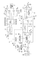
- the block diagram which shows the structure of the hydraulic drive mechanism mounted in the wheel loader.
- the figure which shows the output torque line of an engine.
- the figure which shows an example of a pump displacement-driving circuit pressure characteristic.
- the figure which shows an example of a motor capacity-driving circuit pressure characteristic.
- the figure which shows an example of the vehicle speed-traction force diagram of a wheel loader.
- the block diagram which shows the structure of a vehicle body controller.
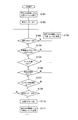
- the flowchart which shows the determination processing for reducing automatically the maximum tractive force during tractive force control.
- the side view of the working machine for showing the definition of a boom angle.
- FIG. 1 is a side view of the wheel loader 50.
- the wheel loader 50 includes a vehicle body 51, a work machine 52, a plurality of tires 55, and a cab 56.
- the work machine 52 is attached to the front portion of the vehicle body 51.
- the work machine 52 includes a boom 53, a bucket 54, a lift cylinder 19, and a bucket cylinder 26.
- the boom 53 is a member for lifting the bucket 54.
- the boom 53 is driven by the lift cylinder 19.
- the bucket 54 is attached to the tip of the boom 53.
- the bucket 54 is dumped and tilted by the bucket cylinder 26.
- the lift cylinder 26 raises and lowers the bucket 54 by operating the boom 53.
- the cab 56 is placed on the vehicle body 51.
- FIG. 2 is a block diagram showing a configuration of the hydraulic drive mechanism 30 mounted on the wheel loader 50.
- the hydraulic drive mechanism 30 mainly includes an engine 1, a first hydraulic pump 4, a second hydraulic pump 2, a charge pump 3, a traveling hydraulic motor 10, an engine controller 12 a, a vehicle body controller 12, and a drive hydraulic circuit 20.
- the first hydraulic pump 4 is driven by the engine 1 to discharge hydraulic oil.
- the traveling hydraulic motor 10 is driven by the hydraulic oil discharged from the first hydraulic pump 4.
- the wheel loader 50 travels when the traveling hydraulic motor 10 rotationally drives the tire 55 described above. That is, the hydraulic drive mechanism 30 employs a so-called 1-pump 1-motor HST system.
- the engine 1 is a diesel engine, and output torque generated by the engine 1 is transmitted to the second hydraulic pump 2, the charge pump 3, the first hydraulic pump 4, and the like.
- the hydraulic drive mechanism 30 is provided with an engine rotation speed sensor 1 a that detects the actual rotation speed of the engine 1.
- the engine rotation speed sensor 1a corresponds to the engine rotation speed detector of the present invention.
- the engine 1 is connected to a fuel injection device 1b.
- the engine controller 12a described later controls the output torque of the engine 1 (hereinafter referred to as “engine torque”) and the rotation speed by controlling the fuel injection device 1b.
- the first hydraulic pump 4 is driven by the engine 1 to discharge hydraulic oil.
- the first hydraulic pump 4 is a variable displacement hydraulic pump.
- the hydraulic oil discharged from the first hydraulic pump 4 is sent to the traveling hydraulic motor 10 through the drive hydraulic circuit 20.
- the drive hydraulic circuit 20 includes a first drive circuit 20a and a second drive circuit 20b.
- the traveling hydraulic motor 10 is driven in one direction (for example, forward direction).
- the traveling hydraulic motor 10 is driven in the other direction (for example, the reverse direction).
- the drive hydraulic circuit 20 is provided with a drive circuit pressure detector 17.
- the drive circuit pressure detector 17 detects the pressure of hydraulic oil (hereinafter referred to as “drive circuit pressure”) supplied to the traveling hydraulic motor 10 via the first drive circuit 20a or the second drive circuit 20b.
- the drive circuit pressure detection unit 17 includes a first drive circuit pressure sensor 17a and a second drive circuit pressure sensor 17b.
- the first drive circuit pressure sensor 17a detects the hydraulic pressure of the first drive circuit 20a.
- the second drive circuit pressure sensor 17b detects the hydraulic pressure of the second drive circuit 20b.
- the first drive circuit pressure sensor 17 a and the second drive circuit pressure sensor 17 b send detection signals to the vehicle body controller 12.
- the first hydraulic pump 4 is connected to an FR switching unit 5 and a pump capacity control cylinder 6 for controlling the discharge direction of the first hydraulic pump 4.
- the FR switching unit 5 is an electromagnetic control valve that switches the supply direction of hydraulic oil to the pump displacement control cylinder 6 based on a control signal from the vehicle body controller 12.
- the FR switching unit 5 switches the discharge direction of the first hydraulic pump 4 by switching the supply direction of the hydraulic oil to the pump displacement control cylinder 6.
- the FR switching unit 5 switches the discharge direction of the first hydraulic pump 4 between discharge to the first drive circuit 20a and discharge to the second drive circuit 20b.
- the pump displacement control cylinder 6 is driven by being supplied with hydraulic oil via the pump pilot circuit 32, and changes the tilt angle of the first hydraulic pump 4.
- the pump capacity control unit 7 is disposed in the pump pilot circuit 32.
- the pump displacement control unit 7 connects the pump displacement control cylinder 6 to either the pump pilot circuit 32 or the hydraulic oil tank.
- the pump displacement control unit 7 is an electromagnetic control valve that is controlled based on a control signal from the vehicle body controller 12.
- the pump displacement control unit 7 adjusts the tilt angle of the first hydraulic pump 4 by controlling the pressure of the hydraulic oil in the pump displacement control cylinder 6.
- the pump pilot circuit 32 is connected to the charge circuit 33 and the hydraulic oil tank via a cut-off valve 47.
- the pilot port of the cutoff valve 47 is connected to the first drive circuit 20a and the second drive circuit 20b via the shuttle valve 46.
- the shuttle valve 46 introduces the larger one of the hydraulic pressure of the first drive circuit 20 a and the hydraulic pressure of the second drive circuit 20 b to the pilot port of the cutoff valve 47. That is, the drive circuit pressure is applied to the pilot port of the cutoff valve 47.
- the cut-off valve 47 causes the charge circuit 33 and the pump pilot circuit 32 to communicate with each other when the drive circuit pressure is lower than a predetermined cut-off pressure. As a result, hydraulic oil is supplied from the charge circuit 33 to the pump pilot circuit 32.
- the cut-off valve 47 causes the pump pilot circuit 32 to communicate with the hydraulic oil tank and allows the hydraulic oil in the pump pilot circuit 32 to escape to the hydraulic oil tank. Thereby, when the hydraulic pressure of the pump pilot circuit 32 decreases, the capacity of the first hydraulic pump 4 is reduced, and an increase in the drive circuit pressure is suppressed.
- the charge pump 3 is a pump that is driven by the engine 1 and supplies hydraulic oil to the drive hydraulic circuit 20.
- the charge pump 3 is connected to the charge circuit 33.
- the charge pump 3 supplies hydraulic oil to the pump pilot circuit 32 via the charge circuit 33.
- the charge circuit 33 is connected to the first drive circuit 20a via the first check valve 41.
- the first check valve 41 allows the flow of hydraulic oil from the charge circuit 33 to the first drive circuit 20a, but restricts the flow of hydraulic oil from the first drive circuit 20a to the charge circuit 33.
- the charge circuit 33 is connected to the second drive circuit 20b via the second check valve 42.
- the second check valve 42 allows the flow of hydraulic oil from the charge circuit 33 to the second drive circuit 20b, but restricts the flow of hydraulic oil from the second drive circuit 20b to the charge circuit 33.
- the charge circuit 33 is connected to the first drive circuit 20a via the first relief valve 43.
- the first relief valve 43 is opened when the hydraulic pressure of the first drive circuit 20a becomes greater than a predetermined pressure.
- the charge circuit 33 is connected to the second drive circuit 20b via the second relief valve 44.
- the second relief valve 44 is opened when the hydraulic pressure of the second drive circuit 20b becomes greater than a predetermined pressure.
- the charge circuit 33 is connected to the hydraulic oil tank via the low pressure relief valve 45.
- the low pressure relief valve 45 is opened when the hydraulic pressure of the charge circuit 33 becomes higher than a predetermined relief pressure. Thereby, the drive circuit pressure is adjusted so as not to exceed a predetermined relief pressure.
- the predetermined relief pressure of the low pressure relief valve 45 is considerably lower than the relief pressure of the first relief valve 43 and the relief pressure of the second relief valve 44. Therefore, when the drive circuit pressure becomes lower than the hydraulic pressure of the charge circuit 33, hydraulic oil is supplied from the charge circuit 33 to the drive hydraulic circuit 20 via the first check valve 41 or the second check valve 42.
- the second hydraulic pump 2 is driven by the engine 1.
- the second hydraulic pump 2 discharges hydraulic oil for driving the lift cylinder 19.
- the hydraulic oil discharged from the second hydraulic pump 2 is supplied to the lift cylinder 19 via the working machine hydraulic circuit 31.
- the work machine 52 is driven.
- the discharge pressure of the second hydraulic pump 2 is detected by a discharge pressure sensor 39.
- the discharge pressure sensor 39 sends a detection signal to the vehicle body controller 12.
- the work machine hydraulic circuit 31 is provided with a work machine control valve 18.
- the work implement control valve 18 is driven according to the operation amount of the work implement operation member 23.
- the work machine operation member 23 is a member for operating the work machine 52.
- the work machine control valve 18 controls the flow rate of the hydraulic oil supplied to the lift cylinder 19 according to the pilot pressure applied to the pilot port.
- the pilot pressure applied to the pilot port of the work implement control valve 18 is controlled by the pilot valve 23 a of the work implement operating member 23.
- the pilot valve 23 a applies a pilot pressure corresponding to the operation amount of the work implement operating member 23 to the pilot port of the work implement control valve 18.
- the lift cylinder 19 is controlled according to the operation amount of the work implement operation member 23.
- the pilot pressure applied to the pilot port of the work implement control valve 18 is detected by the PPC pressure sensor 21.
- the pressure of the hydraulic oil supplied to the lift cylinder 19 is detected by the boom pressure sensor 22.
- the boom pressure sensor 22 corresponds to a boom pressure detection unit of the present invention.
- the PPC pressure sensor 21 and the boom pressure sensor 22 send detection signals to the vehicle body controller 12.
- the lift cylinder 19 is provided with a boom angle detector 38.
- the boom angle detection unit 38 detects a boom angle described later.
- the boom angle detection unit 38 is a sensor that detects the rotation angle of the boom 53.
- the boom angle detection unit 38 may detect the stroke amount of the lift cylinder 19 and calculate the rotation angle of the boom 53 from the stroke amount.
- the boom angle detection unit 38 sends a detection signal to the vehicle body controller 12.
- the bucket cylinder 26 is also controlled by a control valve in the same manner as the lift cylinder 19, but is not shown in FIG.
- the traveling hydraulic motor 10 is a variable displacement hydraulic motor.
- the traveling hydraulic motor 10 is driven by the hydraulic oil discharged from the first hydraulic pump 4 to generate a driving force for traveling.
- the traveling hydraulic motor 10 is provided with a motor cylinder 11a and a motor capacity controller 11b.
- the motor cylinder 11 a changes the tilt angle of the traveling hydraulic motor 10.
- the motor capacity control unit 11 b is an electromagnetic control valve that is controlled based on a control signal from the vehicle body controller 12.
- the motor capacity control unit 11 b controls the motor cylinder 11 a based on a control signal from the vehicle body controller 12.
- the motor cylinder 11 a and the motor capacity control unit 11 b are connected to a motor pilot circuit 34.
- the motor pilot circuit 34 is connected to the first drive circuit 20a via a check valve 48.
- the check valve 48 allows the flow of hydraulic oil from the first drive circuit 20a to the motor pilot circuit 34, but restricts the flow of hydraulic oil from the motor pilot circuit 34 to the first drive circuit 20a.
- the motor pilot circuit 34 is connected to the second drive circuit 20b via the check valve 49.
- the check valve 49 allows the flow of hydraulic oil from the second drive circuit 20b to the motor pilot circuit 34, but restricts the flow of hydraulic oil from the motor pilot circuit 34 to the second drive circuit 20b.
- the check valves 48 and 49 supply the larger hydraulic pressure of the first drive circuit 20 a and the second drive circuit 20 b, that is, hydraulic fluid having a drive circuit pressure, to the motor pilot circuit 34.
- the motor capacity control unit 11b switches the supply direction and supply flow rate of the hydraulic oil from the motor pilot circuit 34 to the motor cylinder 11a based on the control signal from the vehicle body controller 12.
- the vehicle body controller 12 can arbitrarily change the capacity of the traveling hydraulic motor 10.
- the upper limit capacity and the lower limit capacity of the traveling hydraulic motor 10 can be arbitrarily set.
- the hydraulic drive mechanism 30 is provided with a vehicle speed sensor 16.
- the vehicle speed sensor 16 detects the vehicle speed.
- the vehicle speed sensor 16 sends a detection signal to the vehicle body controller 12.
- the vehicle speed sensor 16 detects the vehicle speed, for example, by detecting the rotational speed of the tire drive shaft.
- the wheel loader 50 includes an accelerator operation member 13a, a forward / reverse switching operation member 14, a traction force control operation member 15, an inching operation unit 27, and a setting operation device 24.
- the accelerator operation member 13a is a member for the operator to set the target rotation speed of the engine 1.
- the accelerator operation member 13a is an accelerator pedal, for example, and is operated by an operator.
- the accelerator operation member 13 a is connected to the accelerator operation amount sensor 13.
- the accelerator operation amount sensor 13 is composed of a potentiometer or the like.
- the accelerator operation amount sensor 13 sends a detection signal indicating the operation amount of the accelerator operation member 13a (hereinafter referred to as “accelerator operation amount”) to the engine controller 12a.
- the operator can control the rotational speed of the engine 1 by adjusting the accelerator operation amount.
- the forward / reverse switching operation member 14 is operated to switch the traveling direction of the vehicle.
- the forward / reverse switching operation member 14 is operated by an operator to be switched between a forward position, a reverse position, and a neutral position.
- the forward / reverse switching operation member 14 sends a detection signal indicating the position of the forward / reverse switching operation member 14 to the vehicle body controller 12. The operator can switch between forward and backward movement of the wheel loader 50 by operating the forward / reverse switching operation member 14.
- the tractive force control operation member 15 is, for example, a switch.
- the traction force control operation member 15 is operated by an operator and is operated to switch traction force control on and off.
- the traction force control is control for reducing the maximum traction force of the wheel loader 50.
- the tractive force control being in the off state means a state where the tractive force control is not being executed.
- the traction force control being in the on state means a state in which the traction force control is being executed. The traction force control will be described in detail later.
- the tractive force control operation member 15 sends a detection signal indicating the selected position of the tractive force control operation member 15 to the vehicle body controller 12.
- the inching operation unit 27 includes an inching operation member 27a and an inching operation sensor 27b.
- the inching operation member 27a is operated by an operator.
- the inching operation member 27a is a pedal, for example.
- the inching operation member 27a has both an inching operation function and a brake operation function.
- the inching operation sensor 27 b detects an operation amount of the inching operation member 27 a (hereinafter referred to as “inching operation amount”) and transmits a detection signal to the vehicle body controller 12.
- inching operation amount an operation amount of the inching operation member 27 a
- the vehicle body controller 12 reduces the hydraulic pressure of the pump pilot circuit 32 according to the operation amount of the inching operation member 27a. As a result, the drive circuit pressure decreases, and the rotational speed of the traveling hydraulic motor 10 decreases.
- the inching operation unit 27 is used, for example, when it is desired to increase the rotational speed of the engine 1 but suppress increase in traveling speed. That is, when the rotational speed of the engine 1 is increased by operating the accelerator operation member 13a, the hydraulic pressure of the pump pilot circuit 32 also increases. At this time, the increase in the hydraulic pressure of the pump pilot circuit 32 can be controlled by operating the inching operation member 27a.
- the inching operation member 27a is operated to reduce the vehicle speed and traction force without reducing the engine rotation speed.
- a brake valve 28 is connected to the inching operation member 27a.
- the brake valve 28 controls the supply of hydraulic oil to the hydraulic brake device 29.
- the inching operation member 27 a also serves as an operation member for the hydraulic brake device 29. Until the operation amount of the inching operation member 27a reaches a predetermined amount, only the inching operation described above is performed based on the detection signal from the inching operation sensor 27b. Then, when the operation amount of the inching operation member 27a reaches a predetermined amount, the operation of the brake valve 28 is started, whereby a braking force is generated in the hydraulic brake device 29.
- the braking force of the hydraulic brake device 29 is controlled according to the operation amount of the inching operation member 27a.
- the setting operation device 24 is a device for performing various settings of the wheel loader 50.
- the setting operation device 24 is a display device with a touch panel function, for example.
- the control level of the traction force is set to the first level.
- the maximum traction force of the first level is smaller than the maximum traction force when the traction force control is in the off state.
- the operator can select and set the magnitude of the maximum traction force of the first level in traction force control from a plurality of levels by operating the setting operation device 24.
- the setting operation device 24 corresponds to a tractive force level changing unit for changing the magnitude of the maximum tractive force of the first level.
- the engine controller 12a is an electronic control unit having an arithmetic device such as a CPU and various memories.
- the engine controller 12a controls the engine 1 so that the set target rotational speed can be obtained.
- FIG. 3 shows an output torque line of the engine 1.
- the output torque line of the engine 1 indicates the relationship between the rotational speed of the engine 1 and the upper limit of the engine torque that can be output by the engine 1 at each rotational speed.
- a solid line L100 indicates an engine output torque line when the accelerator operation amount is 100%.
- This engine output torque line corresponds to, for example, the rating of the engine 1 or the maximum power output.
- the accelerator operation amount of 100% means that the accelerator operation member 13a is operated to the maximum.
- a broken line L75 indicates an engine output torque line when the accelerator operation amount is 75%.
- the engine controller 12a controls the output of the engine 1 so that the engine torque is equal to or less than the engine output torque line.
- the control of the output of the engine 1 is performed, for example, by controlling the upper limit value
- the vehicle body controller 12 is an electronic control unit having an arithmetic device such as a CPU and various memories.
- the vehicle body controller 12 controls the capacity of the first hydraulic pump 4 and the capacity of the traveling hydraulic motor 10 by electronically controlling the control valves based on detection signals from the detection units.
- the vehicle body controller 12 outputs a command signal to the pump displacement control unit 7 based on the engine speed detected by the engine speed sensor 1a.
- FIG. 4 shows an example of pump capacity-drive circuit pressure characteristics.
- the pump capacity-drive circuit pressure characteristic indicates the relationship between the pump capacity and the drive circuit pressure.
- L11 to L16 in the figure are lines showing the pump displacement-drive circuit pressure characteristics that are changed according to the engine speed.
- the body displacement controller 12 controls the flow rate of the pump displacement control unit 7 based on the engine rotation speed, whereby the pump displacement / drive circuit pressure characteristic is changed to L11 to L16. Thereby, the pump capacity is controlled to a magnitude corresponding to the engine rotation speed and the drive circuit pressure.
- the vehicle body controller 12 processes detection signals from the engine rotation speed sensor 1a and the drive circuit pressure detection unit 17, and outputs a motor capacity command signal to the motor capacity control unit 11b.
- the vehicle body controller 12 sets the motor capacity from the value of the engine speed and the value of the drive circuit pressure with reference to the motor capacity-drive circuit pressure characteristics stored in the vehicle body controller 12.
- the vehicle body controller 12 outputs a tilt angle change command corresponding to the set motor capacity to the motor capacity controller 11b.
- FIG. 5 shows an example of motor capacity-drive circuit pressure characteristics.
- a solid line L21 in the figure is a line that defines the motor capacity with respect to the drive circuit pressure in a state where the engine speed is a certain value.
- the motor capacity here corresponds to the tilt angle of the traveling hydraulic motor 10.
- the tilt angle is minimum (Min). Thereafter, as the drive circuit pressure increases, the tilt angle gradually increases (inclined portion L22 indicated by a solid line). After the tilt angle reaches the maximum (Max), the tilt angle maintains the maximum tilt angle (Max) even if the drive circuit pressure increases.
- the inclined portion L22 defines the target pressure of the drive circuit pressure. That is, the vehicle body controller 12 increases the capacity of the traveling hydraulic motor when the drive circuit pressure becomes larger than the target pressure. Further, when the drive circuit pressure becomes smaller than the target pressure, the capacity of the traveling hydraulic motor is reduced. The target pressure is determined according to the engine speed. That is, the inclined portion L22 shown in FIG.
- the inclined portion L22 is controlled so that the tilt angle increases from a state where the drive circuit pressure is lower, and reaches the maximum tilt angle when the drive circuit pressure is lower. (Refer to the inclined portion L23 of the lower broken line in FIG. 5).
- the minimum tilt angle (Min) is maintained until the drive circuit pressure becomes higher, and the maximum tilt angle (Max) is reached with the drive circuit pressure being higher.
- the wheel loader 50 can change the traction force and the vehicle speed steplessly, and can automatically shift the vehicle speed from zero to the maximum speed without shifting operation.
- FIG. 6 the wheel loader 50 can change the traction force and the vehicle speed steplessly, and can automatically shift the vehicle speed from zero to the maximum speed without shifting operation.
- the inclined portion L22 is shown with the inclination emphasized for easy understanding, but is actually substantially horizontal. Therefore, when the drive circuit pressure reaches the target pressure, the motor capacity is switched between the minimum value (or minimum limit value) and the maximum value (or maximum limit value). However, when the drive circuit pressure reaches the target pressure, the command value is not changed immediately, but a time delay occurs. This time delay is the reason why the inclined portion L22 exists.
- the vehicle body controller 12 executes traction force control when the traction force control operation member 15 is operated.
- the vehicle body controller 12 changes the maximum traction force of the vehicle by changing the upper limit capacity of the traveling hydraulic motor 10. For example, as shown in FIG. 5, the vehicle body controller 12 outputs a command signal to the motor capacity control unit 11b so that the upper limit capacity is changed from Max to any one of Ma, Mb, and Mc.
- the vehicle speed-traction force characteristic changes as shown by a line La in FIG.
- the maximum traction force is reduced as compared with the line L1 indicating the vehicle speed-traction force characteristic in a state where the traction force control is not performed.
- the maximum traction force of the vehicle is reduced to a preset maximum traction force of the first level.
- the setting operation device 24 described above can select and set the magnitude of the first level maximum traction force in the traction force control from a plurality of levels. Specifically, the setting operation device 24 can select a level to be set as the first level from three levels of level A, level B, and level C.
- Level A is a level of traction force corresponding to the above-described upper limit capacity Ma.
- Level B is a level of traction force corresponding to the above-described upper limit capacity Mb.
- Level C is a level of traction force corresponding to the above-described upper limit capacity Mc.
- FIG. 7 shows traction force ratio information that defines the relationship between the traction force ratio and the accelerator operation amount.
- the tractive force ratio indicates the ratio of the maximum tractive force in the tractive force control when the maximum tractive force is 100% when the tractive force control is in the off state.
- Lv1 is first level tractive force ratio information (hereinafter referred to as “first tractive force ratio information”).
- first tractive force ratio information when the accelerator operation amount is equal to or less than a predetermined threshold A, the tractive force ratio is constant at R1.
- the traction force ratio increases according to the accelerator operation amount.
- the vehicle body controller 12 increases the upper limit capacity of the traveling hydraulic motor 10 so that the maximum traction force as indicated by the first traction force ratio information Lv1 is obtained. Control.
- Lv2 is second level tractive force ratio information (hereinafter referred to as “second tractive force ratio information”).
- the tractive force ratio of the second level Lv2 is smaller than the tractive force ratio of the first level Lv1.
- the tractive force ratio of the second level Lv2 is smaller than the tractive force ratio of the first level Lv1 by a predetermined change amount dR.
- the change amount dR is preferably 5% or more and 15% or less.
- the change amount dR is, for example, 10%.
- the vehicle body controller 12 controls the upper limit capacity of the traveling hydraulic motor 10 so that the maximum traction force as indicated by the second traction force ratio information Lv2 is obtained when the determination condition is satisfied during the traction force control.
- a determination process for automatically reducing the maximum traction force in the traction force control will be described in detail.
- the vehicle body controller 12 includes a traction force control unit 61, a work situation determination unit 62, a work implement raising stall determination unit 63, a boom angle determination unit 64, a drive circuit pressure determination unit 65, an engine.
- a rotation speed determination unit 66 and a change flag determination unit 67 are included.
- FIG. 9 is a flowchart showing a determination process for changing the control level of the traction force from the first level to the second level during the traction force control.
- step S101 the tractive force control unit 61 sets the tractive force control level to the first level.
- step S102 the tractive force control unit 61 sets the change flag to OFF.
- the change flag is set to ON when the tractive force control level is lowered from the first level to the second level.
- the change flag is set to OFF when the tractive force control level is not lowered from the first level to the second level. That is, when the change flag is off, the tractive force control unit 61 maintains the tractive force control level at the first level.
- the work situation determination section 62 determines whether or not the excavation flag is on.
- the excavation flag is on, it means that the work phase is excavation.
- the work situation determination unit 62 determines whether the work situation is excavation based on the traveling state of the vehicle and the operating state of the work implement 52.
- the work situation determination unit 62 sets the excavation flag to ON when it is determined that the work situation is excavation.
- the work situation determination unit 62 sets the excavation flag to OFF. Specific work situation determination processing will be described later.
- step S104 the work implement raising stall determination unit 63 determines whether or not the work implement raising stall flag is on.
- the fact that the work machine raising stall flag is on means that the work machine 52 is in the raised stall state.
- the raised stall state is a state in which the boom 53 does not operate despite the boom raising operation by the work implement operating member 23.
- the work implement raising stall determining unit 63 determines whether or not the work implement 52 is in the raised stall state based on the operation amount of the work implement operating member 23 and a boom pressure described later.
- the work machine raising stall determination unit 63 sets the work machine raising stall flag to ON.
- the work implement raised stall determination unit 63 sets the work implement raised stall flag to OFF. Specific determination processing for determining whether or not the work machine is in the raised stall state will be described later.
- the boom angle determination unit 64 determines whether or not the boom angle is equal to or less than a predetermined angle threshold value B1.
- the boom angle determination unit 64 performs the above determination based on the detection signal from the boom angle detection unit 38.
- the boom angle is an angle ⁇ formed between a line connecting the boom pin 57 and the bucket pin 58 and the horizontal direction with the horizontal direction set to 0 degree in a side view.
- the angle below the horizontal direction is a negative value
- the angle above the horizontal direction is a positive value.
- the boom angle is defined to increase upward.
- the angle threshold B1 corresponds to a boom angle in a state where the bucket 54 is placed on the ground.
- the angle threshold B1 is ⁇ 10 degrees or less.
- the angle threshold B1 is ⁇ 20 degrees or less.
- the boom angle being equal to or less than the predetermined angle threshold value B1 means that the bucket 54 cannot be raised while the bucket 54 is pushed into an object such as earth and sand.
- step S106 the drive circuit pressure determination unit 65 determines whether or not the drive circuit pressure is equal to or higher than a predetermined hydraulic pressure threshold C1.
- the drive circuit pressure determination unit 65 performs the above determination based on the detection signal from the drive circuit pressure detection unit 17.
- the hydraulic pressure threshold C1 is a value that can be regarded as a traction force that is large enough to perform the scooping operation.
- step S107 the engine rotation speed determination unit 66 determines whether or not the engine rotation speed is greater than or equal to a predetermined rotation speed threshold value D1.
- the engine rotation speed determination unit 66 performs the above determination based on the detection signal from the engine rotation speed sensor 1a.
- the rotation speed threshold D1 is a value that can prevent the engine rotation speed from rapidly decreasing when the control level of the traction force is lowered from level 1 to level 2. As shown in FIG. 3, the rotation speed threshold D1 is the engine rotation speed when the upper limit of the engine torque reaches the maximum value Tmax on the output torque line, that is, the maximum torque rotation speed.
- step S108 the tractive force control unit 61 sets the tractive force control level to the first level. That is, when at least one of the conditions from step S103 to step S107 is not satisfied in a state where the control level of the tractive force is the first level, the control level of the tractive force is maintained at the first level.
- the tractive force control level is returned from the second level to the first level. Therefore, the tractive force control unit 61 does not reduce the maximum tractive force when the work phase is not excavation.
- the tractive force control unit 61 does not reduce the maximum tractive force when the work implement 52 is not in the raised stall state.
- the tractive force control unit 61 does not reduce the maximum tractive force when the drive circuit pressure is not equal to or greater than the predetermined hydraulic pressure threshold C1.
- the traction force control unit 61 does not reduce the maximum traction force when the boom angle is not equal to or less than the predetermined angle threshold value B1.
- the tractive force control unit 61 does not reduce the maximum tractive force when the engine rotational speed is not equal to or greater than the predetermined rotational speed threshold D1.
- step S109 the change flag determination unit 67 determines whether or not the change flag is off. That is, the change flag determination unit 67 determines whether or not the traction force control level is the first level. If the change flag is off, that is, if the control level of the traction force is the first level, the process proceeds to step S110.
- step S110 the tractive force control unit 61 sets the change flag to ON.
- step S111 the tractive force control unit 61 changes the tractive force control level from the first level to the second level. Thereby, the tractive force control part 61 controls the maximum tractive force based on the 2nd tractive force ratio information Lv2 shown in FIG. Thereby, the maximum traction force is reduced.
- step S109 if the change flag is not off, the control level of the traction force is maintained at the second level, and the determinations from step S103 to step S109 are repeated. Then, when any of the conditions from step S103 to step S107 is not satisfied, the control level of the traction force is returned from the second level to the first level.
- the tractive force control unit 61 changes the tractive force more slowly when returning the tractive force control level from the second level to the first level than when reducing the tractive force from the first level to the second level. In other words, the traction force control unit 61 changes the maximum traction force more slowly when increasing the maximum traction force in the traction force control than when reducing the maximum traction force.
- FIG. 11A shows the change speed of the command value of the motor capacity when the motor capacity is increased. That is, FIG. 11A shows the change speed of the command value of the motor capacity when the maximum traction force is increased.
- FIG. 11B shows the change speed of the command value of the motor capacity when the motor capacity is decreased. That is, FIG.
- 11B shows the change speed of the command value of the motor capacity when the maximum traction force is reduced. As shown in FIG. 11, time T1 is greater than time T2. Therefore, the traction force control unit 61 changes the command value of the motor capacity more slowly when increasing the maximum traction force than when decreasing the maximum traction force.
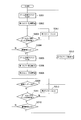
- FIG. 12 is a flowchart showing a process for determining whether or not the work phase is excavation.
- the work situation determination section 62 sets the excavation flag to off.
- the work situation determination section 62 determines whether or not the boom pressure reduction flag is on.
- the boom pressure reduction flag being on means that the bucket is in an empty state. The boom pressure reduction flag determination process will be described later.
- step S203 it is determined whether or not the boom angle is smaller than a predetermined angle threshold B2.
- the angle threshold B2 corresponds to a boom angle when the bucket is placed on the ground.
- the angle threshold B2 may be the same as the angle threshold B1 described above.
- the work situation determination section 62 determines whether or not the boom pressure is equal to or higher than the first boom pressure determination value.
- the boom pressure is a hydraulic pressure supplied to the lift cylinder 19 when the lift cylinder 19 is extended.
- the boom pressure is detected by the boom pressure sensor 22 described above.
- the first boom pressure determination value is a boom pressure value that can be taken during excavation.
- the first boom pressure determination value is obtained and set in advance by experiment or simulation.
- the first boom pressure determination value is a value corresponding to the boom angle.
- the vehicle body controller 12 stores boom pressure determination value information (hereinafter referred to as “first boom pressure determination value information”) indicating the relationship between the first boom pressure determination value and the boom angle.
- the first boom pressure determination value information is, for example, a table or map showing the relationship between the first boom pressure determination value and the boom angle.
- the work situation determination section 62 determines the first boom pressure determination value according to the boom angle by referring to the first boom pressure determination value information.
- step S205 the work situation determination section 62 sets the excavation flag to ON. That is, the work situation determination unit 62 determines that the work situation is excavation when all the conditions from step S202 to step S204 are satisfied. This is because when all the conditions from step S202 to step S204 are satisfied, it can be considered that the wheel loader 50 has entered the preparatory stage for excavation. When at least one of the conditions of steps S202, S203, and S204 is not satisfied, the determinations from step S202 to step S204 are repeated.
- step S206 the work situation determination section 62 sets the boom pressure reduction flag to OFF.
- step S207 the work situation determination section 62 determines whether or not the FNR recognition value is F.
- the FNR recognition value is information indicating whether the vehicle is in a forward drive state, a reverse drive state, or a neutral state.
- An FNR recognition value of F means that the vehicle is in a forward traveling state.
- An FNR recognition value of R means that the vehicle is in a reverse drive state.
- An FNR recognition value of N means that the vehicle is in a neutral state.
- the work situation determination unit 62 determines whether or not the FNR recognition value is F based on the detection signal from the forward / reverse switching operation member 14. When the FNR recognition value is not F, the process proceeds to step S209.
- step S209 the work situation determination section 62 sets the excavation flag to OFF. That is, the excavation flag is set to OFF when the vehicle is in a reverse state or a neutral state.
- step S207 when the FNR recognition value is F, the process proceeds to step S208.
- step S208 the work situation determination section 62 determines whether or not the boom pressure reduction flag is on.
- the process proceeds to step S209.
- the boom pressure reduction flag is not on, the process returns to step S207. Therefore, once it is determined that the work phase is excavation, the forward / reverse switching operation member 14 is thereafter switched from the forward movement position to the reverse movement position, or the forward / backward switching operation member 14 is changed from the forward movement position to the neutral position. Until switching, the excavation flag is kept on even if the conditions from step S202 to step S204 are not satisfied. Even if the forward / reverse switching operation member 14 is maintained at the forward position, the excavation flag is changed to off when the boom pressure reduction flag is set to on.
- FIG. 13 is a flowchart showing a process for determining whether or not the boom pressure reduction flag is ON. As shown in FIG. 13, in step S301, the work situation determination section 62 sets the boom pressure reduction flag to OFF.
- step S302 the work situation determination section 62 starts measuring the first timer.
- the first timer measures the duration for which the condition for setting the boom pressure reduction flag to ON is satisfied.
- the work situation determination section 62 determines whether or not the boom pressure is smaller than the second boom pressure determination value.
- the second boom pressure determination value is a boom pressure value that can be taken when the bucket is in an empty state.
- the vehicle body controller 12 stores boom pressure determination value information (hereinafter referred to as “second boom pressure determination value information”) indicating the relationship between the second boom pressure determination value and the boom angle.
- the second boom pressure determination value information is, for example, a table or map showing the relationship between the second boom pressure determination value and the boom angle.
- the work situation determination unit 62 determines the second boom pressure determination value according to the boom angle by referring to the second boom pressure determination value information.
- the second boom pressure determination value information when the boom angle is greater than 0 degrees, the second boom pressure determination value is constant at a value when the boom angle is 0 degrees.
- the boom pressure increase rate when the boom angle is greater than or equal to 0 degrees is smaller than the boom pressure increase rate when the boom angle is less than 0 degrees, so the second boom pressure determination when the boom angle is greater than 0 degrees This is because the value can be approximated by the second boom pressure determination value when the boom angle is 0 degree.
- step S304 the work situation determination section 62 determines whether or not the time measured by the first timer is equal to or greater than a predetermined time threshold E1. That is, the duration determination unit 67 determines whether or not the duration of the state in which the condition of step S303 is satisfied is equal to or greater than a predetermined time threshold E1.
- the time threshold E1 is set to a time that can be considered that the condition of step S303 is not temporarily satisfied.
- the determination in step S303 is repeated.
- step S304 when the time measured by the first timer is equal to or greater than the predetermined time threshold E1, the process proceeds to step S305.
- step S305 the work situation determination section 62 sets the boom pressure reduction flag to ON.
- step S306 the work situation determination section 62 ends the measurement of the first timer.
- step S303 when the boom pressure is not smaller than the second boom pressure determination value, the process proceeds to step S307.
- step S307 the work situation determination section 62 resets the first timer.
- step S308 the work situation determination section 62 starts measuring the second timer.
- step S309 the work situation determination section 62 determines whether or not the excavation flag is on. When the excavation flag is on, the process proceeds to step S310.
- step S310 the work situation determination section 62 ends the measurement of the second timer. And it returns to step S301 and the work situation determination part 62 sets a boom pressure fall flag to OFF.
- step S309 when the excavation flag is not on, the process proceeds to step S311.
- step S311 the work situation determination section 62 determines whether or not the boom pressure is smaller than the second boom pressure determination value. When the boom pressure is smaller than the second boom pressure determination value, the process proceeds to step S312.
- step S312 the work situation determination section 62 determines whether the time measured by the second timer is equal to or greater than a predetermined time threshold E2. When the time measured by the second timer is equal to or greater than the predetermined time threshold E2, the process proceeds to step S310. Similarly to the above, in step S310, the work situation determination section 62 ends the measurement of the second timer, and in step S301, sets the boom pressure reduction flag to OFF. In step S312, when the time measured by the second timer is not equal to or greater than the predetermined time threshold E2, the process returns to step S309.
- step S311 when the boom pressure is not smaller than the second boom pressure determination value, the process proceeds to step S313.
- step S313 the work situation determination section 62 resets the second timer and returns to step S309.
- FIG. 14 is a flowchart showing a process for determining whether or not the work implement raising stall flag is ON. As shown in FIG. 14, in step S401, work implement raising stall determination unit 63 sets the work implement raising stall flag to OFF.
- step S402 the work implement lifting stall determination unit 63 determines whether or not the discharge pressure of the second hydraulic pump 2 (hereinafter referred to as “second pump pressure”) is smaller than the boom pressure.
- the work implement raising stall determination unit 63 determines whether or not the second pump pressure is smaller than the boom pressure based on detection signals from the boom pressure sensor 22 and the discharge pressure sensor 39. That the second pump pressure is smaller than the boom pressure means that the driving force by the second hydraulic pump 2 is defeated by the load applied to the lift cylinder 19.
- step S403 the work implement raising stall determination unit 63 determines whether or not the second pump pressure is equal to or lower than a predetermined pump pressure threshold H1. Based on the detection signals from the work implement raising stall determination unit 63 and the discharge pressure sensor 39, it is determined whether or not the second pump pressure is equal to or less than the pump pressure threshold value H1.
- the pump pressure threshold value H1 corresponds to the magnitude of the traction force that is large enough to perform the scooping operation.
- the work implement raising stall determining unit 63 determines whether or not the boom raising PPC pressure is equal to or higher than the first PPC pressure threshold G1.
- the boom raising PPC pressure is a pilot pressure generated by a boom raising operation by the work implement operation unit 23. That is, the boom raising PPC pressure corresponds to the operation amount of the work implement operation unit 23 for operating the boom 53 in the direction in which the bucket 54 is raised.
- the boom raising PPC pressure is detected by the PPC pressure sensor 21 described above.
- the first PPC pressure threshold G1 is a value at which it can be considered that the operator is performing a boom raising operation.
- step S405 the work implement lifting stall determination unit 63 determines whether the FNR recognition value is F or R.
- step S406 work implement raising stall determination unit 63 determines whether or not the work implement raising stall flag is off. When the work machine raising stall flag is OFF, the process proceeds to step S407.
- step S407 the work implement raising stall determination unit 63 sets the work implement raising stall flag to ON.
- step S408 work implement raising stall determination unit 63 starts measuring the change amount of the boom angle. That is, the work implement raising stall determination unit 63 measures the amount of change in the boom angle from the time when the work implement raising stall flag is set to ON. Then, the process returns to step S404.
- step S409 the work implement raising stall determining unit 63 determines whether or not the boom raising PPC pressure is equal to or less than the second PPC pressure threshold G2.
- the second PPC pressure threshold G2 is an operation amount of the work machine operation unit 23 that can be considered that the operator is not performing the boom raising operation.
- step S409 when the boom raising PPC pressure is equal to or lower than the second PPC pressure threshold G2, the process proceeds to step S410.
- step S410 the work implement raising stall determination unit 63 sets the work implement raising stall flag to OFF. Therefore, when the work implement raising stall flag is on, in step S410, the work implement raising stall determination unit 63 returns the work implement raising stall flag to off.
- the work implement raising stall determination unit 63 maintains the work implement raising stall flag off. That is, the work implement raising stall determining unit 63 determines that the work implement 52 is not in the raised stall state when the boom raising operation is no longer performed by the work implement operating unit 23.
- step S411 work implement raising stall determination unit 63 resets the measurement of the change amount of the boom angle. That is, the work implement raising stall determination unit 63 measures the change amount of the boom angle while the work implement raising stall is on.
- step S409 when the boom raising PPC pressure is not less than or equal to the second PPC pressure threshold G2, the process proceeds to step S405. That is, when the boom raising PPC pressure is a value between the first PPC pressure threshold value G1 and the second PPC pressure threshold value G2, the work implement raising stall flag is not changed and the current state is maintained.
- step S405 Even when the condition of step S405 is not satisfied, the work implement raising stall determination unit 63 sets the work implement raising stall flag to OFF in step S410. That is, the work implement raising stall determining unit 63 determines that the work implement 52 is not in the raised stall state when the forward / reverse switching operation member 14 is in the neutral position.
- step S412 the work implement raising stall determination unit 63 determines whether or not the boom angle change amount is equal to or greater than a predetermined angle change amount threshold B3.
- the angle change amount threshold B3 is a change amount of the boom angle that can be considered that the operation of the boom 53 is not stopped.
- the angle change amount threshold B3 is preferably 3 degrees or less.
- the angle change amount threshold B3 is, for example, 1 degree.
- step S402 When the condition of step S402 or step S403 is not satisfied, the determination after step S402 is repeated. When the condition of step S412 is not satisfied, the process returns to step S404.
- the wheel loader 50 lowers the control level of the traction force from the first level to the second level when the above-described determination condition is satisfied during the traction force control. Thereby, the maximum traction force is reduced.
- the determination condition is satisfied, the operator is trying to raise the bucket 54 in a state where a sufficiently large traction force is generated during excavation work, but the bucket 54 is not raised.
- the maximum traction force is automatically reduced in such a state, whereby the work machine 52 can be raised and returned from the stalled state. Further, since it is not necessary for the operator to perform an operation for changing the maximum traction force level, it is possible to suppress a decrease in operability.
- the work implement raising stall determination unit 63 detects a state in which the boom 53 is lowered by determining whether or not the boom angle is equal to or less than a predetermined angle threshold. Thereby, it is possible to accurately determine a state in which the boom 53 cannot be raised while the boom 53 is lowered.
- the operator can change the magnitude of the maximum traction force of the first level by operating the setting operation device 24.
- the tractive force control unit 61 reduces the maximum tractive force to a value smaller than the first level maximum tractive force. Thereby, the operator can set the required maximum traction force more finely according to the work situation.
- the traction force control unit 61 When the determination condition is not satisfied during the traction force control, the traction force control unit 61 returns the control level of the traction force to the first level. Thereby, an appropriate maximum traction force according to the work situation can be obtained.
- the tractive force control unit 61 changes the pump capacity more slowly when returning the tractive force control level from the second level to the first level than when reducing the tractive force control level from the first level to the second level. For this reason, the rapid increase of tractive force can be suppressed. Thereby, generation
- the traction force control unit 61 changes the pump capacity more quickly when the traction force control level is lowered from the first level to the second level than when the traction force control level is returned from the second level to the first level. Thereby, in the wheel loader 50 which concerns on this embodiment, when the working machine 52 raises and falls into a stalled state, it can come out from such a state rapidly.
- the wheel loader 50 equipped with an HST system of one pump and one motor including one hydraulic pump and the traveling hydraulic motor 10 has been described as an example.
- the present invention is not limited to this.
- the present invention may be applied to a wheel loader equipped with a 1-pump 2-motor HST system including one first hydraulic pump and two traveling hydraulic motors.
- the setting operation device 24 can change the maximum tractive force of the first level in three stages.
- the setting operation device 24 may be capable of changing the first level maximum traction force to a plurality of stages other than the three stages.
- the setting operation device 24 may be capable of continuously changing the maximum traction force of the first level to an arbitrary magnitude.
- the setting operation device 24 may be omitted. That is, the maximum tractive force of the first level may not be changeable.
- the determination condition is not limited to the above, and other conditions may be added. Alternatively, some of the determination conditions described above may be changed.
- the tractive force control unit 61 reduces the maximum tractive force by changing the upper limit capacity of the motor capacity, but may reduce the maximum tractive force by other methods.
- the traction force control unit 61 may reduce the maximum traction force by controlling the drive circuit pressure.
- the drive circuit pressure is controlled, for example, by controlling the capacity of the first hydraulic pump 4.
- the traction force ratio information is set so that the traction force ratio increases as the accelerator operation amount increases, but the traction force ratio information is set so that the traction force ratio is constant regardless of the accelerator operation amount. It may be set.
- a wheel loader and a wheel loader control method capable of raising a work machine during excavation and returning it from a stalled state and suppressing deterioration in operability.
Landscapes
- Engineering & Computer Science (AREA)
- General Engineering & Computer Science (AREA)
- Mechanical Engineering (AREA)
- Mining & Mineral Resources (AREA)
- Civil Engineering (AREA)
- Structural Engineering (AREA)
- Automation & Control Theory (AREA)
- Transportation (AREA)
- Operation Control Of Excavators (AREA)
- Control Of Fluid Gearings (AREA)
Description
1a エンジン回転速度センサ
2 第2油圧ポンプ
4 第1油圧ポンプ
10 走行用油圧モータ
14 前後進切換操作部材
15 牽引力制御操作部材
17 駆動回路圧検出部
22 ブーム圧センサ
23 作業機操作部材
24 設定操作装置
50 ホイールローダ
52 作業機
61 牽引力制御部
62 作業局面判定部
63 作業機上げストール判定部
64 ブーム角度判定部
65 駆動回路圧判定部
66 エンジン回転速度判定部
Claims (18)
- ブームと、バケットと、前記ブームを動作させることによって前記バケットを昇降させるリフトシリンダとを有する作業機と、
エンジンと、
前記エンジンによって駆動される第1油圧ポンプと、
前記第1油圧ポンプから吐出された作動油によって駆動される走行用油圧モータと、
前記エンジンによって駆動され、前記リフトシリンダを駆動するための作動油を吐出する第2油圧ポンプと、
前記作業機を操作するための作業機操作部材と、
最大牽引力を低減させる牽引力制御のオンオフを切り換えるために操作される牽引力制御操作部材と、
前記走行用油圧モータを駆動する作動油の圧力である駆動回路圧を検出する駆動回路圧検出部と、
作業局面が掘削であるか否かを判定する作業局面判定部と、
前記作業機操作部材の操作にも関わらず前記バケットが上昇しない上げストール状態に前記作業機がなっているか否かを判定する作業機上げストール判定部と、
前記駆動回路圧が所定の油圧閾値以上であるか否かを判定する駆動回路圧判定部と、
前記牽引力制御がオン状態であるときには、前記牽引力制御がオフ状態での最大牽引力よりも最大牽引力を低減させる牽引力制御部と、
を備え、
前記牽引力制御部は、前記作業局面が掘削であることと、前記作業機が上げストール状態であることと、前記駆動回路圧が前記所定の油圧閾値以上であることとを含む判定条件が前記牽引力制御中に満たされたときに、最大牽引力をさらに低減させる、
ホイールローダ。 - エンジン回転速度を検出するエンジン回転速度検出部と、
前記エンジン回転速度が所定の回転速度閾値以上であるか否かを判定するエンジン回転速度判定部と、
をさらに備え、
前記判定条件は、前記エンジン回転速度が、前記所定の回転速度閾値以上であることをさらに含む、
請求項1に記載のホイールローダ。 - 前記ブームの水平方向に対する角度であるブーム角度が所定の角度閾値以下であるか否かを判定するブーム角度判定部をさらに備え、
前記判定条件は、前記ブーム角度が所定の角度閾値以下であることをさらに含む、
請求項1に記載のホイールローダ。 - 前記牽引力制御部は、前記牽引力制御において、牽引力の制御レベルを、前記牽引力制御がオフ状態での最大牽引力よりも最大牽引力が小さくなる第1レベルに設定し、
前記牽引力制御部は、前記判定条件が前記牽引力制御中に満たされたときには、最大牽引力の制御レベルを、前記第1レベルよりも最大牽引力が小さくなる第2レベルに変更する、
請求項1から3のいずれかに記載のホイールローダ。 - 前記第1レベルの最大牽引力の大きさを変更するための牽引力レベル変更部をさらに備える、
請求項4に記載のホイールローダ。 - 前記牽引力制御部は、前記牽引力制御中に前記判定条件が満たされなくなったときは、牽引力の制御レベルを前記第1レベルに戻す、
請求項4に記載のホイールローダ。 - 前記牽引力制御部は、牽引力の制御レベルを前記第1レベルに戻すときには、牽引力の制御レベルを前記第2レベルに変更するときよりも、牽引力をゆっくりと変化させる、
請求項6に記載のホイールローダ。 - 前記作業局面判定部は、車両の走行状態と前記作業機の作動状態とに基づいて、前記作業局面が掘削であるか否かを判定する、
請求項1に記載のホイールローダ。 - 前記リフトシリンダに供給される作動油の圧力を検出するブーム圧検出部をさらに備え、
前記作業機上げストール判定部は、前記作業機操作部材の操作量と、前記リフトシリンダに供給される作動油の圧力とに基づいて、前記作業機が前記上げストール状態になっているか否かを判定する、
請求項1に記載のホイールローダ。 - 車両の進行方向を切り換えるために操作され、前進位置と後進位置と中立位置とに切り換えられる前後進切換操作部材をさらに備え、
前記作業機上げストール判定部は、前記前後進切換操作部材が中立位置であるときには、前記作業機が前記上げストール状態になっていないと判定する、
請求項1に記載のホイールローダ。 - 前記所定の回転速度閾値は、エンジン回転速度と、各エンジン回転速度において前記エンジンが出力できるエンジントルクの上限との関係を示す出力トルク線において、前記エンジントルクの上限が最大となるときのエンジン回転速度である、
請求項2に記載のホイールローダ。 - 牽引力制御部は、前記走行用油圧モータの傾転角を制御することで前記走行用油圧モータの容量を制御し、前記走行用油圧モータの容量の上限容量を制御することにより、前記最大牽引力の制御を行う、
請求項1に記載のホイールローダ。 - 前記牽引力制御部は、前記作業局面が掘削ではないときには、前記最大牽引力の低減を行わない、
請求項1に記載のホイールローダ。 - 前記牽引力制御部は、前記作業機が前記上げストール状態ではないときには、前記最大牽引力の低減を行わない、
請求項1に記載のホイールローダ。 - 前記牽引力制御部は、前記駆動回路圧が前記所定の油圧閾値以上ではないときには、前記最大牽引力の低減を行わない、
請求項1に記載のホイールローダ。 - 前記牽引力制御部は、前記エンジン回転速度が前記所定の回転速度閾値以上ではないときには、前記最大牽引力の低減を行わない、
請求項2に記載のホイールローダ。 - 前記牽引力制御部は、前記ブーム角度が前記所定の角度閾値以下ではないときには、前記最大牽引力の増大を行わない、
請求項3に記載のホイールローダ。 - ブームと、バケットと、前記ブームを動作させることによって前記バケットを昇降させるリフトシリンダとを有する作業機と、
エンジンと、
前記エンジンによって駆動される第1油圧ポンプと、
前記第1油圧ポンプから吐出された作動油によって駆動される走行用油圧モータと、
前記エンジンによって駆動され、前記リフトシリンダを駆動するための作動油を吐出する第2油圧ポンプと、
前記作業機を操作するための作業機操作部材と、
最大牽引力を低減させる牽引力制御のオンオフを切り換えるために操作される牽引力制御操作部材と、
前記走行用油圧モータを駆動する作動油の圧力である駆動回路圧を検出する駆動回路圧検出部と、
を備えるホイールローダの制御方法であって、
作業局面が掘削であるか否かを判定するステップと、
前記作業機操作部材の操作にも関わらず前記バケットが上昇しない上げストール状態に前記作業機がなっているか否かを判定するステップと、
前記駆動回路圧が所定の油圧閾値以上であるか否かを判定するステップと、
前記牽引力制御がオン状態であるときには、前記牽引力制御がオフ状態での最大牽引力よりも最大牽引力を低減させるステップと、
前記作業局面が掘削であることと、前記作業機が上げストール状態であることと、前記駆動回路圧が前記所定の油圧閾値以上であることとを含む判定条件が前記牽引力制御中に満たされたときに、最大牽引力をさらに低減させるステップと、
を備えるホイールローダの制御方法。
Priority Applications (5)
| Application Number | Priority Date | Filing Date | Title |
|---|---|---|---|
| EP12791680.7A EP2667059B1 (en) | 2012-03-30 | 2012-05-15 | Wheel loader and method for controlling wheel loader |
| CN201280001365.5A CN103597256B (zh) | 2012-03-30 | 2012-05-15 | 轮式装载机及轮式装载机的控制方法 |
| JP2012524797A JP5092070B1 (ja) | 2012-03-30 | 2012-05-15 | ホイールローダ及びホイールローダの制御方法 |
| US13/700,412 US8639429B2 (en) | 2012-03-30 | 2012-05-15 | Wheel loader and method for controlling a wheel loader |
| US14/133,742 US9031760B2 (en) | 2012-03-30 | 2013-12-19 | Wheel loader and method for controlling a wheel loader |
Applications Claiming Priority (2)
| Application Number | Priority Date | Filing Date | Title |
|---|---|---|---|
| JP2012-078942 | 2012-03-30 | ||
| JP2012078942 | 2012-03-30 |
Related Child Applications (2)
| Application Number | Title | Priority Date | Filing Date |
|---|---|---|---|
| US13/700,412 A-371-Of-International US8639429B2 (en) | 2012-03-30 | 2012-05-15 | Wheel loader and method for controlling a wheel loader |
| US14/133,742 Continuation US9031760B2 (en) | 2012-03-30 | 2013-12-19 | Wheel loader and method for controlling a wheel loader |
Publications (1)
| Publication Number | Publication Date |
|---|---|
| WO2013145341A1 true WO2013145341A1 (ja) | 2013-10-03 |
Family
ID=49258696
Family Applications (1)
| Application Number | Title | Priority Date | Filing Date |
|---|---|---|---|
| PCT/JP2012/062350 Ceased WO2013145341A1 (ja) | 2012-03-30 | 2012-05-15 | ホイールローダ及びホイールローダの制御方法 |
Country Status (5)
| Country | Link |
|---|---|
| US (2) | US8639429B2 (ja) |
| EP (1) | EP2667059B1 (ja) |
| JP (1) | JP5092070B1 (ja) |
| CN (1) | CN103597256B (ja) |
| WO (1) | WO2013145341A1 (ja) |
Cited By (3)
| Publication number | Priority date | Publication date | Assignee | Title |
|---|---|---|---|---|
| WO2020003638A1 (ja) * | 2018-06-29 | 2020-01-02 | 株式会社小松製作所 | 作業機械、および作業機械を含むシステム |
| WO2020003636A1 (ja) * | 2018-06-29 | 2020-01-02 | 株式会社小松製作所 | 作業機械、および作業機械を含むシステム |
| WO2020003637A1 (ja) * | 2018-06-29 | 2020-01-02 | 株式会社小松製作所 | 作業機械、および作業機械を含むシステム |
Families Citing this family (28)
| Publication number | Priority date | Publication date | Assignee | Title |
|---|---|---|---|---|
| WO2013145341A1 (ja) * | 2012-03-30 | 2013-10-03 | 株式会社小松製作所 | ホイールローダ及びホイールローダの制御方法 |
| JP5192601B1 (ja) * | 2012-08-20 | 2013-05-08 | 株式会社小松製作所 | 作業車両及び作業車両の制御方法 |
| KR102218354B1 (ko) * | 2014-02-24 | 2021-02-23 | 스미토모 겐키 가부시키가이샤 | 쇼벨 및 쇼벨의 제어방법 |
| DE102014221594B4 (de) * | 2014-10-23 | 2020-03-19 | Danfoss Power Solutions Gmbh & Co. Ohg | Hydrostatisches Bremskonzept |
| KR102452805B1 (ko) * | 2015-05-12 | 2022-10-11 | 현대두산인프라코어 주식회사 | 휠 로더의 제어 방법 및 시스템 |
| JP6552916B2 (ja) | 2015-08-24 | 2019-07-31 | 株式会社小松製作所 | ホイールローダ |
| US9994104B2 (en) * | 2015-09-03 | 2018-06-12 | Deere & Company | System and method of reacting to wheel slip in a traction vehicle |
| JP6569181B2 (ja) * | 2016-03-16 | 2019-09-04 | 日立建機株式会社 | 作業車両 |
| US11242672B2 (en) * | 2017-09-29 | 2022-02-08 | Hitachi Construction Machinery Co., Ltd. | Wheel loader |
| US10544565B2 (en) | 2017-10-17 | 2020-01-28 | Caterpillar Inc. | On demand machine rimpull adjustment to prevent tire slip |
| JP6749885B2 (ja) * | 2017-12-28 | 2020-09-02 | 日立建機株式会社 | ホイールローダ |
| JP6736597B2 (ja) * | 2018-03-28 | 2020-08-05 | 日立建機株式会社 | ホイールローダ |
| CN108533541B (zh) * | 2018-06-26 | 2019-08-20 | 广西柳工机械股份有限公司 | 装载机闭式静液压驱动系统 |
| WO2020065915A1 (ja) * | 2018-09-28 | 2020-04-02 | 日立建機株式会社 | ホイールローダ |
| US10913435B2 (en) * | 2018-09-28 | 2021-02-09 | Goodrich Corporation | Hydraulic braking system and method |
| US11286646B2 (en) * | 2019-03-13 | 2022-03-29 | Hitachi Construction Machinery Co., Ltd. | Loading vehicle |
| FR3096698B1 (fr) * | 2019-06-03 | 2021-04-30 | Manitou Bf | Engin de manutention de charge |
| JP7368130B2 (ja) | 2019-07-19 | 2023-10-24 | 株式会社小松製作所 | 作業機械および作業機械の制御方法 |
| WO2021055917A1 (en) * | 2019-09-19 | 2021-03-25 | Clark Equipment Company | Drive motor displacement control |
| US11872885B2 (en) * | 2019-10-31 | 2024-01-16 | Deere & Company | Trailing vehicle traction control system with force increase control |
| DE102019220357A1 (de) * | 2019-12-20 | 2021-06-24 | Zf Friedrichshafen Ag | Verfahren und Steuereinrichtung zum Betreiben von einer selbstfahrenden Arbeitsmaschine |
| US12146301B2 (en) | 2021-04-29 | 2024-11-19 | Caterpillar Inc. | Automatic torque control system |
| JP2023111667A (ja) * | 2022-01-31 | 2023-08-10 | 株式会社小松製作所 | 作業車両及び作業車両を制御するための方法 |
| CN118489041A (zh) * | 2022-03-18 | 2024-08-13 | 日立建机株式会社 | 变速装置 |
| EP4286708A4 (en) * | 2022-03-18 | 2025-01-08 | Hitachi Construction Machinery Co., Ltd. | POWER TRANSMISSION DEVICE FOR A VEHICLE |
| US11898326B2 (en) * | 2022-04-27 | 2024-02-13 | Cnh Industrial America Llc | System and method for load control of a lift arm |
| CN115142491B (zh) * | 2022-06-21 | 2023-07-07 | 江苏电子信息职业学院 | 一种电驱动装载机辅助铲掘控制系统及方法 |
| CN117755837B (zh) * | 2024-01-12 | 2026-04-28 | 中铁工程装备集团有限公司 | 行星轮式刮板输送机及其控制方法 |
Citations (4)
| Publication number | Priority date | Publication date | Assignee | Title |
|---|---|---|---|---|
| JPH07229560A (ja) * | 1994-02-18 | 1995-08-29 | Komatsu Ltd | 静油圧−機械式変速機の制御装置 |
| JP2004024172A (ja) * | 2002-06-27 | 2004-01-29 | Iseki & Co Ltd | ロータリの耕耘ピッチ制御装置 |
| JP2008144942A (ja) | 2006-12-13 | 2008-06-26 | Komatsu Ltd | 建設車両の牽引力制御装置 |
| JP2011063945A (ja) * | 2009-09-15 | 2011-03-31 | Kcm:Kk | 産業用車両 |
Family Cites Families (12)
| Publication number | Priority date | Publication date | Assignee | Title |
|---|---|---|---|---|
| US4017739A (en) * | 1975-02-27 | 1977-04-12 | General Electric Company | Lifting force responsive load control for electrically propelled earthmoving vehicles |
| US4776751A (en) * | 1987-08-19 | 1988-10-11 | Deere & Company | Crowd control system for a loader |
| US6321535B2 (en) * | 1997-11-21 | 2001-11-27 | Komatsu Ltd. | Hydraulic circuit for working vehicle |
| US6234254B1 (en) * | 1999-03-29 | 2001-05-22 | Caterpillar Inc. | Apparatus and method for controlling the efficiency of the work cycle associated with an earthworking machine |
| JP5129493B2 (ja) * | 2007-03-12 | 2013-01-30 | 日立建機株式会社 | 作業車両の走行制御装置 |
| JP5074086B2 (ja) * | 2007-04-26 | 2012-11-14 | 株式会社小松製作所 | 建設車両 |
| WO2008143568A1 (en) * | 2007-05-18 | 2008-11-27 | Volvo Construction Equipment Ab | A method for recuperating potential energy during a lowering operation of a load |
| US7853389B2 (en) * | 2007-10-29 | 2010-12-14 | Ford Global Technologies, Llc | Traction control for performance and demonstration spin |
| JP5072926B2 (ja) * | 2009-09-03 | 2012-11-14 | 株式会社小松製作所 | 作業車両 |
| JP5261419B2 (ja) * | 2010-03-05 | 2013-08-14 | 株式会社小松製作所 | 作業車両及び作業車両の制御方法 |
| JP5113946B1 (ja) * | 2012-03-27 | 2013-01-09 | 株式会社小松製作所 | 作業車両及び作業車両の制御方法 |
| WO2013145341A1 (ja) * | 2012-03-30 | 2013-10-03 | 株式会社小松製作所 | ホイールローダ及びホイールローダの制御方法 |
-
2012
- 2012-05-15 WO PCT/JP2012/062350 patent/WO2013145341A1/ja not_active Ceased
- 2012-05-15 JP JP2012524797A patent/JP5092070B1/ja active Active
- 2012-05-15 EP EP12791680.7A patent/EP2667059B1/en active Active
- 2012-05-15 CN CN201280001365.5A patent/CN103597256B/zh active Active
- 2012-05-15 US US13/700,412 patent/US8639429B2/en active Active
-
2013
- 2013-12-19 US US14/133,742 patent/US9031760B2/en active Active
Patent Citations (4)
| Publication number | Priority date | Publication date | Assignee | Title |
|---|---|---|---|---|
| JPH07229560A (ja) * | 1994-02-18 | 1995-08-29 | Komatsu Ltd | 静油圧−機械式変速機の制御装置 |
| JP2004024172A (ja) * | 2002-06-27 | 2004-01-29 | Iseki & Co Ltd | ロータリの耕耘ピッチ制御装置 |
| JP2008144942A (ja) | 2006-12-13 | 2008-06-26 | Komatsu Ltd | 建設車両の牽引力制御装置 |
| JP2011063945A (ja) * | 2009-09-15 | 2011-03-31 | Kcm:Kk | 産業用車両 |
Non-Patent Citations (1)
| Title |
|---|
| See also references of EP2667059A4 |
Cited By (12)
| Publication number | Priority date | Publication date | Assignee | Title |
|---|---|---|---|---|
| WO2020003638A1 (ja) * | 2018-06-29 | 2020-01-02 | 株式会社小松製作所 | 作業機械、および作業機械を含むシステム |
| WO2020003636A1 (ja) * | 2018-06-29 | 2020-01-02 | 株式会社小松製作所 | 作業機械、および作業機械を含むシステム |
| WO2020003637A1 (ja) * | 2018-06-29 | 2020-01-02 | 株式会社小松製作所 | 作業機械、および作業機械を含むシステム |
| JP2020002694A (ja) * | 2018-06-29 | 2020-01-09 | 株式会社小松製作所 | 作業機械、および作業機械を含むシステム |
| JP2020002696A (ja) * | 2018-06-29 | 2020-01-09 | 株式会社小松製作所 | 作業機械、および作業機械を含むシステム |
| JP2020002695A (ja) * | 2018-06-29 | 2020-01-09 | 株式会社小松製作所 | 作業機械、および作業機械を含むシステム |
| JP7107771B2 (ja) | 2018-06-29 | 2022-07-27 | 株式会社小松製作所 | 作業機械、および作業機械を含むシステム |
| JP7266372B2 (ja) | 2018-06-29 | 2023-04-28 | 株式会社小松製作所 | 作業機械、および作業機械を含むシステム |
| JP7266371B2 (ja) | 2018-06-29 | 2023-04-28 | 株式会社小松製作所 | 作業機械、および作業機械を含むシステム |
| US11753802B2 (en) | 2018-06-29 | 2023-09-12 | Komatsu Ltd. | Work machine and system including work machine |
| US11881061B2 (en) | 2018-06-29 | 2024-01-23 | Komatsu Ltd. | Work machine and system including work machine |
| US12098527B2 (en) | 2018-06-29 | 2024-09-24 | Komatsu Ltd. | Work machine and system including work machine |
Also Published As
| Publication number | Publication date |
|---|---|
| CN103597256A (zh) | 2014-02-19 |
| EP2667059A4 (en) | 2014-04-02 |
| JP5092070B1 (ja) | 2012-12-05 |
| US20140180551A1 (en) | 2014-06-26 |
| US8639429B2 (en) | 2014-01-28 |
| EP2667059B1 (en) | 2016-06-01 |
| CN103597256B (zh) | 2014-12-10 |
| US20130259620A1 (en) | 2013-10-03 |
| EP2667059A1 (en) | 2013-11-27 |
| US9031760B2 (en) | 2015-05-12 |
| JPWO2013145341A1 (ja) | 2015-12-10 |
Similar Documents
| Publication | Publication Date | Title |
|---|---|---|
| JP5092070B1 (ja) | ホイールローダ及びホイールローダの制御方法 | |
| JP5092069B1 (ja) | ホイールローダ及びホイールローダの制御方法 | |
| JP5092071B1 (ja) | ホイールローダ及びホイールローダの制御方法 | |
| JP5161380B1 (ja) | 作業車両及び作業車両の制御方法 | |
| JP5106694B1 (ja) | 作業車両及び作業車両の制御方法 | |
| JP5228132B1 (ja) | ホイールローダ | |
| JP5192605B1 (ja) | ホイールローダ | |
| JP5192601B1 (ja) | 作業車両及び作業車両の制御方法 | |
| JP5113946B1 (ja) | 作業車両及び作業車両の制御方法 | |
| CN104603430A (zh) | 轮式装载机及轮式装载机的发动机控制方法 | |
| CN106133409A (zh) | 轮式装载机及其控制方法 | |
| KR102452805B1 (ko) | 휠 로더의 제어 방법 및 시스템 |
Legal Events
| Date | Code | Title | Description |
|---|---|---|---|
| ENP | Entry into the national phase |
Ref document number: 2012524797 Country of ref document: JP Kind code of ref document: A |
|
| WWE | Wipo information: entry into national phase |
Ref document number: 13700412 Country of ref document: US |
|
| WWE | Wipo information: entry into national phase |
Ref document number: 2012791680 Country of ref document: EP |
|
| 121 | Ep: the epo has been informed by wipo that ep was designated in this application |
Ref document number: 12791680 Country of ref document: EP Kind code of ref document: A1 |
|
| NENP | Non-entry into the national phase |
Ref country code: DE |