WO2013145388A1 - 階調補正方法、イプシロンフィルタの閾値決定装置またはその方法 - Google Patents
階調補正方法、イプシロンフィルタの閾値決定装置またはその方法 Download PDFInfo
- Publication number
- WO2013145388A1 WO2013145388A1 PCT/JP2012/076108 JP2012076108W WO2013145388A1 WO 2013145388 A1 WO2013145388 A1 WO 2013145388A1 JP 2012076108 W JP2012076108 W JP 2012076108W WO 2013145388 A1 WO2013145388 A1 WO 2013145388A1
- Authority
- WO
- WIPO (PCT)
- Prior art keywords
- value
- threshold value
- gradation
- luminance
- epsilon filter
- Prior art date
- Legal status (The legal status is an assumption and is not a legal conclusion. Google has not performed a legal analysis and makes no representation as to the accuracy of the status listed.)
- Ceased
Links
Images



Classifications
-
- G—PHYSICS
- G06—COMPUTING OR CALCULATING; COUNTING
- G06T—IMAGE DATA PROCESSING OR GENERATION, IN GENERAL
- G06T5/00—Image enhancement or restoration
- G06T5/10—Image enhancement or restoration using non-spatial domain filtering
-
- G—PHYSICS
- G09—EDUCATION; CRYPTOGRAPHY; DISPLAY; ADVERTISING; SEALS
- G09G—ARRANGEMENTS OR CIRCUITS FOR CONTROL OF INDICATING DEVICES USING STATIC MEANS TO PRESENT VARIABLE INFORMATION
- G09G5/00—Control arrangements or circuits for visual indicators common to cathode-ray tube indicators and other visual indicators
- G09G5/02—Control arrangements or circuits for visual indicators common to cathode-ray tube indicators and other visual indicators characterised by the way in which colour is displayed
-
- G—PHYSICS
- G06—COMPUTING OR CALCULATING; COUNTING
- G06T—IMAGE DATA PROCESSING OR GENERATION, IN GENERAL
- G06T5/00—Image enhancement or restoration
- G06T5/20—Image enhancement or restoration using local operators
-
- G—PHYSICS
- G06—COMPUTING OR CALCULATING; COUNTING
- G06T—IMAGE DATA PROCESSING OR GENERATION, IN GENERAL
- G06T5/00—Image enhancement or restoration
- G06T5/90—Dynamic range modification of images or parts thereof
- G06T5/94—Dynamic range modification of images or parts thereof based on local image properties, e.g. for local contrast enhancement
-
- H—ELECTRICITY
- H04—ELECTRIC COMMUNICATION TECHNIQUE
- H04N—PICTORIAL COMMUNICATION, e.g. TELEVISION
- H04N1/00—Scanning, transmission or reproduction of documents or the like, e.g. facsimile transmission; Details thereof
- H04N1/40—Picture signal circuits
- H04N1/407—Control or modification of tonal gradation or of extreme levels, e.g. background level
-
- H—ELECTRICITY
- H04—ELECTRIC COMMUNICATION TECHNIQUE
- H04N—PICTORIAL COMMUNICATION, e.g. TELEVISION
- H04N9/00—Details of colour television systems
- H04N9/64—Circuits for processing colour signals
- H04N9/68—Circuits for processing colour signals for controlling the amplitude of colour signals, e.g. automatic chroma control circuits
- H04N9/69—Circuits for processing colour signals for controlling the amplitude of colour signals, e.g. automatic chroma control circuits for modifying the colour signals by gamma correction
-
- G—PHYSICS
- G09—EDUCATION; CRYPTOGRAPHY; DISPLAY; ADVERTISING; SEALS
- G09G—ARRANGEMENTS OR CIRCUITS FOR CONTROL OF INDICATING DEVICES USING STATIC MEANS TO PRESENT VARIABLE INFORMATION
- G09G2360/00—Aspects of the architecture of display systems
- G09G2360/14—Detecting light within display terminals, e.g. using a single or a plurality of photosensors
- G09G2360/144—Detecting light within display terminals, e.g. using a single or a plurality of photosensors the light being ambient light
-
- G—PHYSICS
- G09—EDUCATION; CRYPTOGRAPHY; DISPLAY; ADVERTISING; SEALS
- G09G—ARRANGEMENTS OR CIRCUITS FOR CONTROL OF INDICATING DEVICES USING STATIC MEANS TO PRESENT VARIABLE INFORMATION
- G09G2360/00—Aspects of the architecture of display systems
- G09G2360/16—Calculation or use of calculated indices related to luminance levels in display data
Definitions
- the present invention relates to Retinex processing, and more particularly, to gradation correction capable of achieving a balance between halo artifacts and Retinex processing.
- Retinex processing is known as a technique for compressing the dynamic range by image processing.
- the original image is divided into a reflected light component and an illumination light component using a low-pass filter, the illumination light component is corrected, and the corrected illumination light component and reflected light component are combined. Is output.
- the edge reproduction is improved.
- the filter size of the low-pass filter is increased, a halo artifact may occur at the boundary with the edge portion.
- an edge-preserving low-pass filter has been proposed, and an ⁇ filter is known as one of them.
- the ⁇ filter is provided with a threshold value ⁇ in advance, and among all the pixels in the fixed region, only a pixel whose pixel value is within the threshold value ⁇ with respect to the central pixel in the fixed region is adopted as a calculation target.
- the threshold value ⁇ is reduced, halo artifacts can be reduced.
- the stereoscopic effect that is the effect of the Retinex processing is also impaired.
- Patent Document 1 discloses a technique for changing the threshold value ⁇ according to the edge strength in the target region. This is because the threshold value ⁇ is determined by focusing on the edge portion where the halo artifact occurs. Only.
- An object of the present invention is to provide an epsilon filter threshold value determining apparatus or method based on the visibility characteristics and / or taking into account the influence of ambient light, and a gradation correction method, which solve the above problems. .
- a gradation correction method is a gradation correction method for performing gradation correction based on Retinex theory in a display device, and each processing based on the maximum luminance and the minimum luminance for each display device.
- An assigned luminance value assigned to a unit gradation is obtained, a threshold value in the epsilon filter is determined based on a luminance difference that can be distinguished in each processing unit gradation so as to have a monotonically increasing relationship with each assigned luminance value, and the epsilon
- gradation correction is performed using the threshold value of the epsilon filter corresponding to the central representative value of the input image data.
- gradation correction can be performed for each region.
- the distinguishable luminance difference is determined based on the luminance difference correspondence data that can be distinguished for each luminance. Therefore, gradation correction according to human identification ability is possible.
- the assigned luminance value of each processing unit gradation is obtained based on ambient light in addition to the maximum luminance and the minimum luminance. Therefore, it is possible to perform gradation correction in consideration of ambient light.
- the relational expression of the threshold value in the epsilon filter in each processing unit gradation is dynamically changed based on the environmental light detected by the environmental light detection means. Therefore, even if the ambient light fluctuates, it is possible to perform gradation correction according to this.
- a gradation correction apparatus is a gradation correction apparatus that performs gradation correction based on Retinex theory in a display device, and is provided with input image data of a predetermined region input to the epsilon filter.
- An extraction unit that extracts a central representative value located in the vicinity of the center of the peripheral pixel region used in the epsilon filter calculation, stores a correspondence relationship between the central representative candidate value and the threshold value of the epsilon filter, and stores the central representative value Is given, a threshold value determination unit that determines a corresponding threshold value based on the correspondence relationship, and smoothing calculation is performed on the input image data of the input predetermined region using the threshold value determined by the threshold value determination unit.
- An epsilon filter, and a gradation correction unit that performs gradation correction that performs gradation correction using an output value of the epsilon filter as an illumination light component.
- gradation correction As described above, by varying the threshold value in the epsilon filter in each processing unit gradation according to the central representative value, appropriate gradation correction can be performed for each region.
- the distinguishable luminance difference is determined based on the luminance difference correspondence data that can be distinguished for each luminance. Therefore, gradation correction according to human identification ability is possible.
- An epsilon filter threshold value determination device is an extraction unit that extracts a central representative value located in the vicinity of the center of a peripheral pixel region used in an epsilon filter calculation, the central representative candidate value and the threshold value of the epsilon filter.
- a correspondence relationship is stored, and when the central representative value is given, a threshold value determination unit that outputs a corresponding threshold value based on the correspondence relationship, and a correspondence relationship between the central representative candidate value and the threshold value of the epsilon filter Is a simple increase relationship determined based on a luminance difference that can be distinguished at a specific luminance value.
- the central representative value is the luminance of the central pixel in the peripheral pixel region used in the epsilon filter calculation. Therefore, the peripheral pixels used for the epsilon filtering calculation can be dynamically changed based on the central representative luminance.
- ⁇ (central representative value * ⁇ ) + ⁇ ⁇ and ⁇ are decimal numbers from 0 to 1, and the central representative value is normalized to 0 to 1.
- peripheral pixels used for the epsilon filtering calculation can be dynamically changed according to the pixel characteristics of the region.
- An epsilon filter threshold value variation apparatus includes an ambient light detection unit that detects ambient light, and the threshold determination unit includes the central representative candidate value and the epsilon according to the value of the ambient light.
- a plurality of correspondence relationships with the threshold values of the filter are stored, and one of the plurality of correspondence relationships is selected based on the detected ambient light, and the corresponding threshold value is output. Therefore, the threshold value can be changed in accordance with changes in ambient light.
- the epsilon filter threshold value determining method is configured to discriminate each processing unit gradation for each assigned luminance value of each processing unit gradation based on luminance difference correspondence data that can be distinguished for each luminance. A possible luminance difference is obtained, and based on the luminance difference that can be distinguished for each processing unit gradation, the relationship with the central representative value given to the epsilon filter is simply increased, so that each processing unit gradation is The assigned luminance and the threshold value of the epsilon filter are determined.
- the threshold value can be varied from a high-luminance region in which halo artifacts are likely to be felt to a large value, and to a low-luminance region in which halo artifacts are likely to be felt if the threshold value is not small.
- a gradation correction method is a gradation correction method for performing gradation correction based on Retinex theory in a display device, and each processing based on the maximum luminance and the minimum luminance for each display device.
- An assigned luminance value assigned to a unit gradation is obtained, and a luminance difference that can be discriminated for each assigned luminance value in each processing unit gradation is obtained based on luminance difference correspondence data that can be distinguished for each luminance.
- the luminance difference that can be distinguished in unit gradation is normalized by the difference between the maximum luminance and the minimum luminance of the display device to obtain a normalized distinguishable luminance difference, and thereby the normalized distinguishable luminance in each processing unit gradation A difference is obtained, and a threshold in the epsilon filter in each processing unit gradation is determined based on the normalized distinguishable luminance difference in each processing unit gradation, and the epsilon
- gradation correction is performed using the threshold value of the epsilon filter corresponding to the central representative value of the input image data.
- the distinguishable luminance difference is determined based on the luminance difference correspondence data that can be distinguished for each luminance. Therefore, gradation correction according to human identification ability is possible.
- the “brightness value” uses the V value in the HSV color space, but it may take into account not only the V value itself but also a change in luminance due to the backlight and / or ambient illumination light. .
- Center representative value refers to the brightness value of the pixel obtained in the vicinity of the center of the peripheral pixel region in the epsilon filter.
- luminance is adopted as a value indicating brightness, but the present invention is not limited to this.
- the luminance value of the central pixel is adopted, but the present invention is not limited to this, and includes the case of further considering the luminance of the peripheral pixels in addition to the central pixel. Furthermore, it includes a case where the weighted average is used instead of the simple average.
- the luminance difference that can be distinguished for each luminance refers to a luminance difference that is just (minimum) identifiable by the average observer, and is a concept that includes JND (Just-Noticeable Difference).
- JND index (hereinafter referred to as“ JNDI ”)” refers to a perceptual index determined so that one step in JNDI results in a luminance difference of JND. That is, it is an index that the average observer recognizes as “brightness” at regular intervals.
- DICOM Digital Imaging and Communications in Medicine
- GSDF grayscale standard display function
- Determine permissible value based on JND indicates how far the JND value, which is a luminance difference that can be discriminated, is permissible, and is 10 JND in the following embodiment, but is not limited thereto. .
- “Unit gradation” means one unit constituting each gradation. For example, it means one gradation in 256 gradations.
- “Processing unit gradation” means a gradation for obtaining correspondence between the ⁇ value and unit gradation. In this embodiment, one unit gradation is adopted as the processing unit gradation. May be adopted.
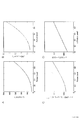
- the relationship of monotonous increase is a concept including not only a linear shape as in the embodiment but also non-linearity as shown in FIG. 3B.
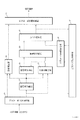
- FIG. 5 is a detailed block diagram of an illumination light separating unit 23.
- FIG. 1 shows a schematic diagram of an image gradation adjusting apparatus including a gradation correcting apparatus according to the present invention.
- the illumination light separation unit 23 corresponds to a gradation correction device.
- HSV color space conversion unit 21 performs conversion from RGB color space to HSV color space.
- the conversion from the HSV color space to the RGB color space is performed using a normal conversion formula.
- HSV color space it is possible to eliminate the saturation reduction effect caused by the brightness adjustment in the YUV color space and to achieve a visually favorable brightness correction.
- the illumination light separation unit 23 is an edge preserving LPF, and calculates a weighted average value of local brightness, that is, an illumination light component.
- the histogram analysis unit 37 generates a 32-part gradation histogram based on the V component of the input image and the output image in the HSV space, and calculates the feature amount of the entire image.
- the parameter automatic adjustment unit 39 determines the illumination light correction amount parameter based on the image feature amount obtained as a result of the histogram analysis.
- the illumination light correction unit 25 corrects the low gradation region of the illumination light component from the parameter value of the illumination light correction amount given from the parameter automatic adjustment unit 39 and the illumination light component L given from the illumination light separation unit 23. .
- the reflectance calculating unit 27 calculates and outputs the reflectance from the logarithmic difference between the illumination light component and the reflected light component (input V value) obtained by the illumination light separating unit 23.
- the image re-synthesis unit 29 calculates a corrected image from the corrected illumination light component calculated by the illumination light correction unit 25 and the reflectance component calculated by the reflectance calculation unit 27.
- the range correction unit 31 performs range correction of the V component of the pixel based on the parameter value of the range correction amount.
- the illumination light correction unit 25 corrects local brightness, and the range correction unit 31 corrects brightness for the entire image. Thereby, the contrast in the whole image can be optimized.
- the histogram analysis unit 37 generates a gradation histogram of 32 divisions from the V value corrected by the range correction unit 31, calculates the feature amount of the entire image, and gives it to the parameter automatic control unit 39.
- the parameter automatic adjustment unit 39 determines a range correction amount parameter based on the given feature amount.
- the saturation correction unit 35 corrects the saturation in the low gradation region. In this embodiment, either enhancement or reduction is selected as the saturation correction in the low gradation region.
- the RGB color space conversion unit 33 performs conversion from the HSV color space to the RGB color space.
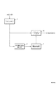
- the line memory 3 stores the HSV input value and outputs the HSV value of the extraction range M * M pixel centered on the target pixel.
- the target pixel luminance calculator 5 extracts the central representative value in the extraction range and gives it to the threshold value determiner 7.
- the V value of the central pixel in the extraction range is used as it is as the central representative value.
- the threshold value determiner 7 receives the central representative value and determines the threshold value ⁇ according to the following equation (1).
- Threshold value ⁇ (central representative value * ⁇ ) + ⁇ (1)
- the central representative value is 0 to 1 because it is the V value of the HSV color space.
- the epsilon filter 12 uses the V value of the M * M pixel given from the line memory 3 and the threshold value ⁇ given from the threshold value determiner 7 to obtain only pixels whose pixel difference value from the target center pixel is less than ⁇ . Extract and perform filtering.
- JND is known as a threshold value that allows a person to recognize the difference in brightness.
- the JND value the luminance difference between the plurality of pixels.
- Such a JND value is small at low luminance and large at high luminance. This is due to the human visual characteristic that it is sensitive to low luminance at low luminance and insensitive to high luminance.
- the present inventor obtains a JND value with respect to pixel luminance for each unit gradation determined from the optical characteristics of each device, and determines the relationship between the central representative value and the threshold value ⁇ from the JND value, so that halo artifacts are obtained. We thought that correction by Retinex processing could be balanced.
- FIG. 3A shows the relationship of the luminance L corresponding to each unit gradation (X) (0 to 1) of the obtained panel.
- the corresponding JND value (identifiable luminance difference) is obtained for the luminance value in the unit gradation (X) (0 to 1) of the obtained panel.
- the unit gradation (X) (0 to For each 1), a corresponding identifiable brightness is obtained.
- the JNDI corresponding to the luminance is obtained from the equation (3), and the luminance corresponding to the JNDI is obtained from the equation (4).
- the difference between the luminance corresponding to the target JNDI and the luminance corresponding to the next JNDI, that is, the JND value at the target luminance is obtained by the following equation (5).
- JND value j2v (JND_INDEX + 1)? J2v (JND_INDEX) ...
- JND or JNDI models include Barten model, Weber model (applicable in medium brightness region), DeVries-Rose model (applicable in low brightness region), or T.
- Various mathematical models such as the Ji model have been proposed.
- the Barten model is a physiological model of the visual system constructed by mathematical description. The conversion formula from luminance to Barten-JNDI can be approximated by Blume et al.
- the JNDI may be a mathematical model or a numerical value found experimentally or empirically by sensory evaluation or the like.
- a model more suitable for visual characteristics may be used.
- the JND value (luminance difference) for each unit gradation is shown in FIG. 3B.
- a pixel value corresponding to the JND value is obtained for each unit gradation of the panel, and this is set as a threshold ⁇ for each unit gradation.
- the unit gradation of the panel corresponding to the JND value is obtained by the following formulas (6) and (7).
- ⁇ _luminance JND / (Lmax-Lmin) (6)
- ⁇ ⁇ _luminance ⁇ (1 / 2.2) (7)
- the threshold ⁇ is obtained by performing inverse gamma correction on the JND value that can be identified for each unit gradation (X) (0 to 1) of the panel to the ratio of the maximum output value of the panel. As a result, the relationship shown in FIG. 3C is obtained.
- FIG. 3D shows an approximation result obtained from a linear function using the least square method.
- the smoothing process in the epsilon filter 12 shown in FIG. 2 is the same as the conventional one, but in the present embodiment, the weighted average is obtained by the following equation (8).
- Equation 1 ⁇ means an operation on a pixel of the size of a low-pass filter (for example, an M * M pixel block, and f (x) and k (x) are expressed by Equation (9) and Equation (10).
- f (xi, j) * Fi, j and k (xi, j) * Fi, j mean convolution operations.
- the Gaussian filter coefficient F (i, j) may be arbitrarily determined.
- the threshold value ⁇ is a variable value that varies based on the central representative value of the extraction range, as in the number (1). That is, the ⁇ Gaussian filter employed in the present embodiment can be said to be an adaptive ⁇ Gaussian filter with a central representative value.
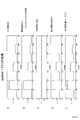
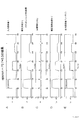
- the input pixel value I includes an AC component at pixel positions 0 to 350. In particular, large alternating current components are contained in the pixel positions 50 to 100, 150 to 200, and 250 to 300.
- the pixel positions 50 to 100, 150 to 200, and 250 to 300 have an alternating current component having a larger amplitude as the peripheral luminance value is higher. That is, the area around the pixel positions 50 to 100 has the largest amplitude. Even in such a case, it is possible to effectively separate the alternating current component (reflectance component) and the direct current component (illumination light component) by adopting a filter using a JND that varies the threshold value.
- the AC components are almost removed from the pixel positions 50 to 100, 150 to 200, and 250 to 300.
- the reflectance R as shown in FIG. 4C, no ripple occurs at the end portions of the pixel positions 50 to 100, but there is a ripple at the end portions of the pixel positions 150 to 200 and 250 to 300. Has occurred.
- FIG. 4E the halo artifact in the portion with the largest illuminance difference was reduced, but the halo artifact should occur in the portion with the small illuminance difference.
- the illumination light component L is almost free of alternating current components at pixel positions 50 to 100, 150 to 200, and 250 to 300.
- the reflectance R as shown in FIG. 5C, the pixel positions 50 to 100 and 150 to 200 have no ripple, but the pixel positions 250 to 300 have some ripples.
- the illuminance difference from which the halo is removed can be reduced.
- the illumination light component L has not been able to remove the AC component having a large amplitude at the pixel positions 50 to 100.
- output data is blurred at pixel positions 50 to 100 having a high luminance value and a large amplitude.
- ⁇ 0.7 * (center pixel value) +0.3 as a linear function of the center representative value.
- FIG. 8C some ripples are generated at the ends of the pixel positions 50 to 100, 150 to 200, and 250 to 300.
- FIG. 8E some halo is generated. This is because at this level, the three-dimensional effect can be emphasized and, as already explained, humans hardly feel it.
- the threshold value ⁇ is a simple increase function with respect to the central pixel value. Accordingly, even if the halo artifact is present to some extent, the high-luminance region where it is difficult for humans to feel it may increase the threshold value, and the low-luminance region where the halo artifact is likely to be felt unless the threshold value is small may decrease the threshold value. it can.
- the threshold ⁇ based on the V value of the center pixel of the low-pass filter
- a different threshold ⁇ can be adopted for each region.
- the threshold value ⁇ is linearly varied so that the V value of the center pixel of the low-pass filter increases as the value increases and decreases as the value decreases.
- a value obtained by multiplying the corrected identifiable luminance difference by a predetermined coefficient in accordance with the allowable number of JND steps may be used as the threshold value of the epsilon filter in each unit gradation.
- the brightness in the HSV color space is adopted as the pixel value, but the luminance in the HLS color space may be adopted. Moreover, you may employ
- the threshold value is changed by the luminance of the central pixel of the low-pass filter.
- the luminance of the central pixel not only the luminance of the central pixel but also the luminance of the surrounding pixels may be further considered.
- an average value of 3 * 3 pixels including the central pixel may be adopted as the central representative value.
- the weighted average may be obtained by increasing the weight as it is located in the center. Further, for example, it may be a weighted average of the entire area of the low-pass filter of 20 * 20 pixels.
- the correspondence between the assigned luminance value assigned to the pixel and each unit gradation is determined by assuming ambient light. That is, the threshold value ⁇ is determined by obtaining the above equation (1) with the ambient light as an assumed fixed value.
- the present invention is not limited to this, and an ambient light sensor 9 for measuring ambient light as shown in FIG. In this way, by using the detection value by the ambient light detection unit, the relational expression with the threshold ⁇ in unit gradation luminance can be dynamically changed.
- the calculation in FIG. 3 may be performed each time, and the ⁇ value when the ambient light fluctuates from the minimum assumed value to the maximum assumed value is calculated in advance, and this correspondence table is calculated. You may make it refer.
- the above units may be realized by either hardware or software.
- the assigned luminance value assigned to the pixel and each unit gradation when determining the correspondence between the assigned luminance value assigned to the pixel and each unit gradation, and further considering the ⁇ characteristics, the assigned luminance value assigned to the pixel and the correspondence between each unit gradation.
- correction for removing the ⁇ characteristic correction is performed on the identifiable luminance difference, and a correspondence between the identifiable luminance difference after the correction and each unit gradation is obtained. This is because the correspondence between the specific luminance and the JND in the luminance has already been obtained as a model in consideration of the ⁇ characteristics that JNDI requires. Therefore, after the ⁇ correction is performed once, the inverse ⁇ correction is performed. Yes. Therefore, such processing is optional.
Landscapes
- Engineering & Computer Science (AREA)
- Physics & Mathematics (AREA)
- General Physics & Mathematics (AREA)
- Theoretical Computer Science (AREA)
- Multimedia (AREA)
- Signal Processing (AREA)
- Computer Hardware Design (AREA)
- Image Processing (AREA)
- Picture Signal Circuits (AREA)
- Processing Of Color Television Signals (AREA)
- Facsimile Image Signal Circuits (AREA)
- Controls And Circuits For Display Device (AREA)
Description
αおよびβは、0から1の小数であり、前記中央代表値は0~1に正規化されている。
図1に、本発明にかかる階調補正装置を含む画像階調調整装置の概要図を示す。この実施形態においては、照明光分離部23が階調補正装置に該当する。
図2を用いて、照明光分離部23の詳細について説明する。
中央代表値は、HSV色空間のV値なので、0~1である。本実施形態においては、下記に説明するようにして、α=0.7、β=0.3とした。
得られたパネルの単位階調(X)(0~1)ごとに、対応する輝度Lの関係を、図3Aに示す。


なお、JNDあるいはJNDIに関するモデルとしては、Bartenモデル、Weberモデル(中輝度領域で適用可能)、DeVries-Roseモデル(低輝度領域で適用可能)、あるいはT.Jiモデル等、様々な数理モデルが提案されている。Bartenモデルは、数学的記述によって構築された視覚系の生理学モデルである。輝度からBarten-JNDIへの変換式はBlumeらによる近似式を用いることができる。また、JNDIは、数理モデルによるものでも、官能評価等によって実験的又は経験的に見出された数値でもよい。さらに、特定のJNDIのみを用いるのではなく、より視覚特性に適合したモデルを用いるようにしてもよい。
ε = ε_luminance ^ (1/2.2) ・・・式(7)
なお、パネルの光学特性がγ=2.2とした場合の変換であり、かかるγについてはこれに限定されない。



本実施形態においては、画素値として HSV色空間における明度を採用したが、HLS色空間における輝度を採用してもよい。また、RGB値、YUV値を採用してもよい。
5 注目画素輝度算出器
7 閾値決定器
9 環境光センサ
12 イプシロンフィルタ
Claims (10)
- 表示装置における、レティネックス理論に基づく階調補正をおこなう階調補正方法であって、
表示装置ごとの最大輝度および最小輝度に基づいて、各処理単位階調に割り当てられる割り当て輝度値を求め、
輝度毎の弁別可能な輝度差対応データに基づき、前記各処理単位階調における、前記各割り当て輝度値について弁別可能な輝度差を求め、
前記各処理単位階調における弁別可能な輝度差に基づき、前記各割り当て輝度値と単調増加の関係となるようイプシロンフィルタにおける閾値を求め、
前記イプシロンフィルタに所定領域の入力画像データが与えられると、この入力画像データの中央代表値に対応するイプシロンフィルタの閾値を用いて、階調補正を行うこと、
を特徴とする階調補正方法。 - 請求項1の階調補正方法において、
前記最大輝度および前記最小輝度に加えて環境光に基づいて、各処理単位階調の前記割り当て輝度値を求めること、
を特徴とする階調補正方法。 - 請求項2の階調補正方法において、
環境光検出手段によって検出された環境光に基づいて、前記各処理単位階調における前記イプシロンフィルタにおける閾値の関係式を動的に変動させること、
を特徴とする階調補正方法。 - 表示装置における、レティネックス理論に基づく階調補正をおこなう階調補正装置であって、
前記イプシロンフィルタに入力される所定領域の入力画像データが与えられると、イプシロンフィルタ演算で用いる周辺画素領域の中央近辺に位置する中央代表値を抽出する抽出部、
前記中央代表候補値とイプシロンフィルタの閾値との対応関係を記憶しており、前記中央代表値が与えられると、前記対応関係に基づき、対応する閾値を決定する閾値決定部、
入力された所定領域の入力画像データについて、前記閾値決定部で決定された閾値を用いて、平滑化演算を行うイプシロンフィルタ、
前記イプシロンフィルタの出力値を照明光成分として、階調補正を行う階調補正を行う階調補正部、
を備えた特徴とする階調補正装置。 - レティネックス処理におけるイプシロンフィルタの閾値決定装置であって、
イプシロンフィルタ演算で用いる周辺画素領域の中央近辺に位置する中央代表値を抽出する抽出部、
前記中央代表候補値とイプシロンフィルタの閾値との対応関係を記憶しており、前記中央代表値が与えられると、前記対応関係に基づき、対応する閾値を出力する閾値決定部、
を備え、
前記中央代表候補値とイプシロンフィルタの閾値との対応関係は、特定の輝度値において弁別可能な輝度差に基づいて決定された単調増加関係であること、
を特徴とするイプシロンフィルタの閾値決定装置。 - 請求項5のイプシロンフィルタの閾値変動装置において、
前記中央代表値は、イプシロンフィルタ演算で用いる周辺画素領域における中央画素の輝度であること、
を特徴とするイプシロンフィルタの閾値変動装置。 - 請求項5または請求項6のイプシロンフィルタの閾値変動装置において、
前記中央代表候補値とイプシロンフィルタの閾値との対応関係は、下記式で表されること、
ε=(中央代表値*α)+β
αおよびβは、0から1の小数であり、前記中央代表値は0~1に正規化されている、
を特徴とするイプシロンフィルタの閾値変動装置。 - 請求項5~7のいずれかのイプシロンフィルタの閾値変動装置において、
環境光を検出する環境光検出部を備え、
前記閾値決定部は、前記環境光の値に応じた、前記中央代表候補値とイプシロンフィルタの閾値との対応関係を複数記憶しており、前記検出された環境光に基づいて、いずれかの複数の対応関係のうちのいずれかを選択して、対応する閾値を出力すること、
を特徴とするイプシロンフィルタの閾値変動装置。 - レティネックス処理におけるイプシロンフィルタの閾値決定方法であって、
割り当てられた各処理単位階調の割り当て輝度値について、輝度毎の弁別可能な輝度差対応データに基づき、前記処理単位階調毎の弁別可能な輝度差を求め、
前記処理単位階調毎の弁別可能な輝度差に基づいて、前記イプシロンフィルタに与えられる中央代表値との関係が単純増加関係となるように、処理単位階調毎の割り当て輝度と前記イプシロンフィルタの閾値を決定すること、
を特徴とするイプシロンフィルタの閾値決定装置。 - 表示装置における、レティネックス理論に基づく階調補正をおこなう階調補正方法であって、
表示装置ごとの最大輝度および最小輝度に基づいて、各処理単位階調に割り当てられる割り当て輝度値を求め、
輝度毎の弁別可能な輝度差対応データに基づき、前記各処理単位階調における、前記各割り当て輝度値について弁別可能な輝度差を求め、
前記各処理単位階調における弁別可能な輝度差を、前記表示装置の最大輝度と最小輝度の差で正規化して正規化弁別可能輝度差を求め、これにより、前記各処理単位階調における正規化弁別可能輝度差を求め、
前記各処理単位階調における前記正規化弁別可能輝度差に基づき、前記各処理単位階調におけるイプシロンフィルタにおける閾値を決定し、
前記イプシロンフィルタに所定領域の入力画像データが与えられると、この入力画像データの中央代表値に対応するイプシロンフィルタの閾値を用いて、階調補正を行うこと、
を特徴とする階調補正方法。
Priority Applications (6)
| Application Number | Priority Date | Filing Date | Title |
|---|---|---|---|
| RU2014137567A RU2611005C2 (ru) | 2012-03-30 | 2012-10-09 | Способ коррекции градаций и устройство или способ определения порогового значения для эпсилон-фильтра |
| CN201280072052.9A CN104246865B (zh) | 2012-03-30 | 2012-10-09 | 灰阶校正方法、ε滤波器的阈值决定装置和其方法 |
| US14/389,611 US9336581B2 (en) | 2012-03-30 | 2012-10-09 | Method for correcting gradations and device or method for determining threshold of epsilon filter |
| AU2012374716A AU2012374716B2 (en) | 2012-03-30 | 2012-10-09 | Method for correcting gradations and device or method for determining threshold of epsilon filter |
| EP12872830.0A EP2833355B1 (en) | 2012-03-30 | 2012-10-09 | Gray-level correction method, threshold determination device for epsilon-filter, and method therefor |
| IN8974DEN2014 IN2014DN08974A (ja) | 2012-03-30 | 2012-10-09 |
Applications Claiming Priority (2)
| Application Number | Priority Date | Filing Date | Title |
|---|---|---|---|
| JP2012079738A JP5470415B2 (ja) | 2012-03-30 | 2012-03-30 | イプシロンフィルタの閾値決定方法およびローパスフィルタの係数決定方法 |
| JP2012-079738 | 2012-03-30 |
Publications (1)
| Publication Number | Publication Date |
|---|---|
| WO2013145388A1 true WO2013145388A1 (ja) | 2013-10-03 |
Family
ID=49258729
Family Applications (1)
| Application Number | Title | Priority Date | Filing Date |
|---|---|---|---|
| PCT/JP2012/076108 Ceased WO2013145388A1 (ja) | 2012-03-30 | 2012-10-09 | 階調補正方法、イプシロンフィルタの閾値決定装置またはその方法 |
Country Status (8)
| Country | Link |
|---|---|
| US (1) | US9336581B2 (ja) |
| EP (1) | EP2833355B1 (ja) |
| JP (1) | JP5470415B2 (ja) |
| CN (1) | CN104246865B (ja) |
| AU (1) | AU2012374716B2 (ja) |
| IN (1) | IN2014DN08974A (ja) |
| RU (1) | RU2611005C2 (ja) |
| WO (1) | WO2013145388A1 (ja) |
Cited By (2)
| Publication number | Priority date | Publication date | Assignee | Title |
|---|---|---|---|---|
| JP2013211662A (ja) * | 2012-03-30 | 2013-10-10 | Eizo Corp | 階調補正装置またはその方法 |
| WO2017085786A1 (ja) * | 2015-11-17 | 2017-05-26 | Eizo株式会社 | 画像変換方法及び装置 |
Families Citing this family (19)
| Publication number | Priority date | Publication date | Assignee | Title |
|---|---|---|---|---|
| AU2014397095B2 (en) * | 2014-06-12 | 2018-07-05 | Eizo Corporation | Haze removal device and image generation method |
| WO2016013125A1 (ja) * | 2014-07-25 | 2016-01-28 | Eizo株式会社 | 映像変換方法、映像変換装置、映像変換用コンピュータプログラム、映像表示システム |
| US20160117993A1 (en) * | 2014-10-22 | 2016-04-28 | Pixtronix, Inc. | Image formation in a segmented display |
| JP2016086347A (ja) * | 2014-10-28 | 2016-05-19 | 三星ディスプレイ株式會社Samsung Display Co.,Ltd. | 画像処理装置、画像処理方法、及びプログラム |
| CN106157904B (zh) * | 2015-04-22 | 2018-07-03 | 深圳市巨烽显示科技有限公司 | 液晶显示器及其显示器自动校正方法和装置 |
| CN104992419A (zh) * | 2015-07-08 | 2015-10-21 | 北京大学深圳研究生院 | 基于jnd因子的超像素高斯滤波预处理方法 |
| US10755673B2 (en) | 2016-05-20 | 2020-08-25 | Schepens Eye Research Institute | Methods and systems for adjusting contrast in devices |
| CN107992182B (zh) | 2017-12-05 | 2021-06-29 | 北京小米移动软件有限公司 | 显示界面图像的方法和装置 |
| JP6970763B2 (ja) * | 2018-02-14 | 2021-11-24 | Eizo株式会社 | 表示システム及びプログラム |
| CN108428436B (zh) * | 2018-05-08 | 2019-12-10 | 京东方科技集团股份有限公司 | 亮度补偿方法、亮度补偿装置、显示装置及存储介质 |
| KR102453070B1 (ko) * | 2018-06-05 | 2022-10-07 | 에이조 가부시키가이샤 | 화상 처리 장치 및 화상 처리 프로그램 |
| CN109525847B (zh) * | 2018-11-13 | 2021-04-30 | 华侨大学 | 一种恰可察觉失真模型阈值计算方法 |
| US11800056B2 (en) | 2021-02-11 | 2023-10-24 | Logitech Europe S.A. | Smart webcam system |
| US11800048B2 (en) | 2021-02-24 | 2023-10-24 | Logitech Europe S.A. | Image generating system with background replacement or modification capabilities |
| WO2022193102A1 (zh) * | 2021-03-15 | 2022-09-22 | 京东方科技集团股份有限公司 | 显示面板的漏光程度的确定方法、装置、系统及测试治具 |
| CN116188282A (zh) * | 2021-11-29 | 2023-05-30 | 中国移动通信有限公司研究院 | 图像增强方法、装置、电子设备及可读存储介质 |
| CN116977939B (zh) * | 2023-08-16 | 2025-12-05 | 江苏中农物联网科技有限公司 | 一种水产养殖智能监控系统 |
| CN117405363B (zh) * | 2023-12-14 | 2024-03-01 | 东南大学 | Mini-LED分区背光显示器的光晕表征方法及系统 |
| CN118762673B (zh) * | 2024-09-05 | 2024-12-17 | 长春希达电子技术有限公司 | Jnd系数取值范围方法及系统 |
Citations (4)
| Publication number | Priority date | Publication date | Assignee | Title |
|---|---|---|---|---|
| JPH0951532A (ja) * | 1995-05-29 | 1997-02-18 | Matsushita Electric Ind Co Ltd | 歪み除去装置 |
| JP2003008935A (ja) | 2001-06-20 | 2003-01-10 | Sony Corp | 画像処理方法および装置 |
| JP2006060792A (ja) * | 2004-07-13 | 2006-03-02 | Microsoft Corp | 3dサブバンド符号化のための組み込み基本レイヤコーデック |
| JP2007281767A (ja) * | 2006-04-05 | 2007-10-25 | Fujitsu Ltd | 画像処理装置、画像処理プログラムおよび画像処理方法 |
Family Cites Families (16)
| Publication number | Priority date | Publication date | Assignee | Title |
|---|---|---|---|---|
| DE69635101T2 (de) * | 1995-11-01 | 2006-06-01 | Canon K.K. | Verfahren zur Extraktion von Gegenständen und dieses Verfahren verwendendes Bildaufnahmegerät |
| WO2001039495A1 (en) * | 1999-11-25 | 2001-05-31 | Matsushita Electric Industrial Co., Ltd. | Method and apparatus for gradation correction, and video display |
| JP4208909B2 (ja) | 2006-08-24 | 2009-01-14 | 株式会社東芝 | 画像処理装置と撮影装置 |
| US8154628B2 (en) | 2006-09-14 | 2012-04-10 | Mitsubishi Electric Corporation | Image processing apparatus and imaging apparatus and method |
| KR100879536B1 (ko) | 2006-10-30 | 2009-01-22 | 삼성전자주식회사 | 영상의 화질 개선을 위한 방법 및 시스템 |
| JP4281786B2 (ja) * | 2006-11-20 | 2009-06-17 | ブラザー工業株式会社 | 画像処理プログラムおよび画像処理装置 |
| JP4746575B2 (ja) * | 2007-03-16 | 2011-08-10 | 株式会社東芝 | 画像処理装置及びその方法 |
| CN101102398B (zh) * | 2007-07-26 | 2010-05-19 | 上海交通大学 | 全自动的实时数字图像处理增强系统 |
| JP5012333B2 (ja) * | 2007-08-30 | 2012-08-29 | コニカミノルタアドバンストレイヤー株式会社 | 画像処理装置および画像処理方法ならびに撮像装置 |
| JP4375464B2 (ja) * | 2007-09-11 | 2009-12-02 | 三菱電機株式会社 | ノイズ低減装置 |
| KR20100099686A (ko) | 2007-12-04 | 2010-09-13 | 소니 주식회사 | 화상 처리 장치 및 방법, 프로그램, 및 기록 매체 |
| JP2009238009A (ja) * | 2008-03-27 | 2009-10-15 | Toshiba Corp | 画像処理装置、及び方法 |
| JP4585602B1 (ja) * | 2009-09-18 | 2010-11-24 | 株式会社東芝 | 画像処理装置、表示装置及び画像処理方法 |
| RU2412554C1 (ru) * | 2010-01-25 | 2011-02-20 | Учреждение Российской академии наук Институт физики полупроводников им. А.В. Ржанова Сибирского отделения РАН (ИФП СО РАН) | Способ компенсации дефектных фоточувствительных элементов многоэлементного фотоприемника |
| CN101916431B (zh) * | 2010-07-23 | 2012-06-27 | 北京工业大学 | 一种低照度图像数据处理方法及系统 |
| CN102044070A (zh) * | 2011-01-10 | 2011-05-04 | 北京师范大学 | 一种基于Retinex的非线性彩色图像增强方法 |
-
2012
- 2012-03-30 JP JP2012079738A patent/JP5470415B2/ja active Active
- 2012-10-09 CN CN201280072052.9A patent/CN104246865B/zh active Active
- 2012-10-09 RU RU2014137567A patent/RU2611005C2/ru not_active IP Right Cessation
- 2012-10-09 WO PCT/JP2012/076108 patent/WO2013145388A1/ja not_active Ceased
- 2012-10-09 IN IN8974DEN2014 patent/IN2014DN08974A/en unknown
- 2012-10-09 US US14/389,611 patent/US9336581B2/en active Active
- 2012-10-09 AU AU2012374716A patent/AU2012374716B2/en not_active Ceased
- 2012-10-09 EP EP12872830.0A patent/EP2833355B1/en active Active
Patent Citations (4)
| Publication number | Priority date | Publication date | Assignee | Title |
|---|---|---|---|---|
| JPH0951532A (ja) * | 1995-05-29 | 1997-02-18 | Matsushita Electric Ind Co Ltd | 歪み除去装置 |
| JP2003008935A (ja) | 2001-06-20 | 2003-01-10 | Sony Corp | 画像処理方法および装置 |
| JP2006060792A (ja) * | 2004-07-13 | 2006-03-02 | Microsoft Corp | 3dサブバンド符号化のための組み込み基本レイヤコーデック |
| JP2007281767A (ja) * | 2006-04-05 | 2007-10-25 | Fujitsu Ltd | 画像処理装置、画像処理プログラムおよび画像処理方法 |
Non-Patent Citations (2)
| Title |
|---|
| "Image Processing for Increasing Contrast of Wide-Dynamic-Rage Image", KONICA MINOLTA TECHNOLOGY REPORT, vol. 4, Retrieved from the Internet <URL:http://www.konicaminolta.jp/about/research/technology_report/2007/pdf/introduce_011.p df> |
| See also references of EP2833355A4 |
Cited By (4)
| Publication number | Priority date | Publication date | Assignee | Title |
|---|---|---|---|---|
| JP2013211662A (ja) * | 2012-03-30 | 2013-10-10 | Eizo Corp | 階調補正装置またはその方法 |
| WO2017085786A1 (ja) * | 2015-11-17 | 2017-05-26 | Eizo株式会社 | 画像変換方法及び装置 |
| JPWO2017085786A1 (ja) * | 2015-11-17 | 2018-08-09 | Eizo株式会社 | 画像変換方法及び装置 |
| US10332485B2 (en) | 2015-11-17 | 2019-06-25 | Eizo Corporation | Image converting method and device |
Also Published As
| Publication number | Publication date |
|---|---|
| AU2012374716A1 (en) | 2014-11-20 |
| EP2833355A1 (en) | 2015-02-04 |
| CN104246865A (zh) | 2014-12-24 |
| RU2611005C2 (ru) | 2017-02-17 |
| AU2012374716B2 (en) | 2016-07-14 |
| US20150117775A1 (en) | 2015-04-30 |
| JP2013210773A (ja) | 2013-10-10 |
| EP2833355A4 (en) | 2015-12-16 |
| US9336581B2 (en) | 2016-05-10 |
| RU2014137567A (ru) | 2016-05-27 |
| JP5470415B2 (ja) | 2014-04-16 |
| EP2833355B1 (en) | 2020-08-19 |
| CN104246865B (zh) | 2017-01-04 |
| IN2014DN08974A (ja) | 2015-05-29 |
Similar Documents
| Publication | Publication Date | Title |
|---|---|---|
| JP5470415B2 (ja) | イプシロンフィルタの閾値決定方法およびローパスフィルタの係数決定方法 | |
| RU2617328C2 (ru) | Устройство и/или способ вывода изображения на экран | |
| US20140092307A1 (en) | Image processing apparatus | |
| WO2014168587A1 (en) | Method and system for processing an input image | |
| CN105191277B (zh) | 基于引导式滤波器的细节增强 | |
| US20140348428A1 (en) | Dynamic range-adjustment apparatuses and methods | |
| JP5596075B2 (ja) | 階調補正装置またはその方法 | |
| KR20150003582A (ko) | 디스플레이의 곡률을 참조하는 영상 처리장치 및 방법 | |
| WO2016065053A2 (en) | Automatic display image enhancement based on user's visual perception model | |
| US9299003B2 (en) | Image processing apparatus, non-transitory computer readable medium, and image processing method | |
| CN118446940A (zh) | 清晰图像的获取方法、设备、介质及移动终端 | |
| KR20160068627A (ko) | 영상 처리 장치, 영상 처리 방법, 및 표시 장치 | |
| KR101987764B1 (ko) | 선명도 향상 장치 및 방법 | |
| KR101389932B1 (ko) | 이미지 톤 매핑 장치 및 방법 | |
| US20220237755A1 (en) | Image enhancement method and image processing device | |
| WO2017085786A1 (ja) | 画像変換方法及び装置 | |
| KR102086756B1 (ko) | 하이 다이내믹 레인지 이미지 생성 장치 및 방법 | |
| CN105282419A (zh) | 去噪声方法以及影像系统 | |
| US9721492B2 (en) | Image display apparatus and method of controlling image display apparatus | |
| JP6627530B2 (ja) | 画像処理装置及びプログラム | |
| Daly et al. | Use of a local cone model to predict essential CSF light adaptation behavior used in the design of luminance quantization nonlinearities | |
| KR101872015B1 (ko) | 적외선 영상 생성장치 및 방법 | |
| CN112631539A (zh) | 显示图像的像素灰度值的映射方法 | |
| WO2020227759A1 (en) | Single image contrast | |
| KR101952394B1 (ko) | 레티넥스 모델 기반 엘이디영상 색 보정 방법 |
Legal Events
| Date | Code | Title | Description |
|---|---|---|---|
| 121 | Ep: the epo has been informed by wipo that ep was designated in this application |
Ref document number: 12872830 Country of ref document: EP Kind code of ref document: A1 |
|
| REEP | Request for entry into the european phase |
Ref document number: 2012872830 Country of ref document: EP |
|
| WWE | Wipo information: entry into national phase |
Ref document number: 2012872830 Country of ref document: EP |
|
| ENP | Entry into the national phase |
Ref document number: 2014137567 Country of ref document: RU Kind code of ref document: A |
|
| ENP | Entry into the national phase |
Ref document number: 2012374716 Country of ref document: AU Date of ref document: 20121009 Kind code of ref document: A |
|
| WWE | Wipo information: entry into national phase |
Ref document number: 14389611 Country of ref document: US |
|
| NENP | Non-entry into the national phase |
Ref country code: DE |