WO2013145479A1 - カテーテル用バルーンおよびバルーンカテーテル - Google Patents
カテーテル用バルーンおよびバルーンカテーテル Download PDFInfo
- Publication number
- WO2013145479A1 WO2013145479A1 PCT/JP2012/083333 JP2012083333W WO2013145479A1 WO 2013145479 A1 WO2013145479 A1 WO 2013145479A1 JP 2012083333 W JP2012083333 W JP 2012083333W WO 2013145479 A1 WO2013145479 A1 WO 2013145479A1
- Authority
- WO
- WIPO (PCT)
- Prior art keywords
- balloon
- catheter
- layer
- intermediate layer
- elastomer
- Prior art date
- Legal status (The legal status is an assumption and is not a legal conclusion. Google has not performed a legal analysis and makes no representation as to the accuracy of the status listed.)
- Ceased
Links
Images

Classifications
-
- A—HUMAN NECESSITIES
- A61—MEDICAL OR VETERINARY SCIENCE; HYGIENE
- A61M—DEVICES FOR INTRODUCING MEDIA INTO, OR ONTO, THE BODY; DEVICES FOR TRANSDUCING BODY MEDIA OR FOR TAKING MEDIA FROM THE BODY; DEVICES FOR PRODUCING OR ENDING SLEEP OR STUPOR
- A61M25/00—Catheters; Hollow probes
- A61M25/10—Balloon catheters
-
- A—HUMAN NECESSITIES
- A61—MEDICAL OR VETERINARY SCIENCE; HYGIENE
- A61L—METHODS OR APPARATUS FOR STERILISING MATERIALS OR OBJECTS IN GENERAL; DISINFECTION, STERILISATION OR DEODORISATION OF AIR; CHEMICAL ASPECTS OF BANDAGES, DRESSINGS, ABSORBENT PADS OR SURGICAL ARTICLES; MATERIALS FOR BANDAGES, DRESSINGS, ABSORBENT PADS OR SURGICAL ARTICLES
- A61L29/00—Materials for catheters, medical tubing, cannulae, or endoscopes or for coating catheters
- A61L29/04—Macromolecular materials
- A61L29/06—Macromolecular materials obtained otherwise than by reactions only involving carbon-to-carbon unsaturated bonds
-
- A—HUMAN NECESSITIES
- A61—MEDICAL OR VETERINARY SCIENCE; HYGIENE
- A61M—DEVICES FOR INTRODUCING MEDIA INTO, OR ONTO, THE BODY; DEVICES FOR TRANSDUCING BODY MEDIA OR FOR TAKING MEDIA FROM THE BODY; DEVICES FOR PRODUCING OR ENDING SLEEP OR STUPOR
- A61M25/00—Catheters; Hollow probes
- A61M25/10—Balloon catheters
- A61M25/1027—Making of balloon catheters
- A61M25/1029—Production methods of the balloon members, e.g. blow-moulding, extruding, deposition or by wrapping a plurality of layers of balloon material around a mandril
-
- B—PERFORMING OPERATIONS; TRANSPORTING
- B29—WORKING OF PLASTICS; WORKING OF SUBSTANCES IN A PLASTIC STATE IN GENERAL
- B29C—SHAPING OR JOINING OF PLASTICS; SHAPING OF MATERIAL IN A PLASTIC STATE, NOT OTHERWISE PROVIDED FOR; AFTER-TREATMENT OF THE SHAPED PRODUCTS, e.g. REPAIRING
- B29C49/00—Blow-moulding, i.e. blowing a preform or parison to a desired shape within a mould; Apparatus therefor
- B29C49/02—Combined blow-moulding and manufacture of the preform or the parison
- B29C49/04—Extrusion blow-moulding
-
- A—HUMAN NECESSITIES
- A61—MEDICAL OR VETERINARY SCIENCE; HYGIENE
- A61M—DEVICES FOR INTRODUCING MEDIA INTO, OR ONTO, THE BODY; DEVICES FOR TRANSDUCING BODY MEDIA OR FOR TAKING MEDIA FROM THE BODY; DEVICES FOR PRODUCING OR ENDING SLEEP OR STUPOR
- A61M25/00—Catheters; Hollow probes
- A61M25/10—Balloon catheters
- A61M2025/1043—Balloon catheters with special features or adapted for special applications
- A61M2025/1075—Balloon catheters with special features or adapted for special applications having a balloon composed of several layers, e.g. by coating or embedding
-
- B—PERFORMING OPERATIONS; TRANSPORTING
- B29—WORKING OF PLASTICS; WORKING OF SUBSTANCES IN A PLASTIC STATE IN GENERAL
- B29C—SHAPING OR JOINING OF PLASTICS; SHAPING OF MATERIAL IN A PLASTIC STATE, NOT OTHERWISE PROVIDED FOR; AFTER-TREATMENT OF THE SHAPED PRODUCTS, e.g. REPAIRING
- B29C49/00—Blow-moulding, i.e. blowing a preform or parison to a desired shape within a mould; Apparatus therefor
- B29C49/08—Biaxial stretching during blow-moulding
- B29C49/10—Biaxial stretching during blow-moulding using mechanical means for prestretching
- B29C49/14—Clamps
-
- B—PERFORMING OPERATIONS; TRANSPORTING
- B29—WORKING OF PLASTICS; WORKING OF SUBSTANCES IN A PLASTIC STATE IN GENERAL
- B29L—INDEXING SCHEME ASSOCIATED WITH SUBCLASS B29C, RELATING TO PARTICULAR ARTICLES
- B29L2031/00—Other particular articles
- B29L2031/753—Medical equipment; Accessories therefor
- B29L2031/7542—Catheters
- B29L2031/7543—Balloon catheters
Definitions
- the present invention relates to a balloon and a balloon catheter.
- the present invention relates to a balloon and a balloon catheter that are inserted into a body cavity or the like.
- a catheter with a balloon is used as a urine for a patient who is difficult to treat a disease or urinate.
- the catheter balloon includes (1) trackability (followability of the balloon to meandering blood vessels and body cavities), (2) permeability to stenotic sites such as blood vessels, and (3) stenotic sites such as calcified blood vessels. (4) Low compliance (appropriate non-extensibility that does not cause a large change in balloon diameter due to a small change in pressure), (5) Sufficient strength to withstand internal pressure and impact during balloon expansion, pressure resistance, etc. Such characteristics are required.
- Balloons used in catheters are particularly important in terms of pressure resistance and compliance characteristics from the viewpoint of safety that minimizes the possibility of causing damage to blood tumors and blood vessels as much as possible.
- the balloon itself becomes hard, so that there is a problem that the flexibility of the balloon is impaired and the passage of the balloon to a stenosis site such as a blood vessel is lowered.
- JP-A-2003-144553 can be cited.
- both ends of a straight pipe portion are tapered, and the thickness of the taper portion everywhere on the tapered portion is determined by the outer diameter of the straight pipe portion and the membrane of the straight pipe portion.
- the balloon which satisfies the relational expression (1) of the thickness, the taper angle, and the distance from the boundary between the straight tube portion and the taper portion is disclosed. Further, according to Patent Document 1, by changing the film thickness of the entire balloon depending on the position, it is possible to simultaneously realize high pressure strength, thinning and flexibility of the balloon portion.
- Japanese Unexamined Patent Application Publication No. 2006-110392 is a technology that focuses on compliance that solves this problem.
- 2006-110392 discloses a semi-compliant balloon formed from a polyurethane block copolymer exhibiting a flexibility of 0.025 to 0.045 mm / atm in an expansion pressure range of 6 atm to 19 atm, and 6 atm to An axially non-compliant balloon formed from a polyurethane block copolymer exhibiting a compliance of 0.01 to 0.25 mm / atm in an inflation pressure range of 14 atm is disclosed.
- a balloon formed of a non-compliant material such as nylon needs to have a sufficiently large diameter even in a deflated state due to its compliance characteristics, a stent is deployed and a folded balloon is introduced into the patient's body.
- a folded balloon has the problem of causing non-uniform expansion of the stent.
- the invention described in Japanese Patent Laid-Open No. 2006-110392 can solve this problem.
- the balloon described in FIG. 1 of the above Japanese Patent Application Laid-Open No. 2003-144553 and the example is such that the film thickness of the balloon in the tapered portion gradually decreases from the opening side toward the straight tube side. Is formed.
- the straight tube portion of the balloon disclosed in Japanese Patent Application Laid-Open No. 2003-144553 is relatively thin, it can be expected to some extent in the passage to a stenosis site such as a blood vessel.
- the balloon material actually used in the examples is only a polyamide-based elastomer, the pressure resistance is inferior to that of PET or the like (in the examples, the average breaking pressure is 21.3 atm), and the straight pipe portion is thin. As a result, there is a problem of pinholes.
- the film thickness of Japanese Patent Application Laid-Open No. 2003-144553 is not uniform, there is a possibility that a large change in balloon diameter may occur due to a small change in pressure, and there is a problem that the compliance characteristics remain uneasy.
- the invention of Japanese Patent Application Laid-Open No. 2006-110392 which focuses on compliance characteristics, was created from the viewpoint of suppressing / preventing the folded balloon from causing uneven expansion of the stent.
- a balloon is formed using a monolayer film made of a semi-compliant polyurethane copolymer.
- the outer wall in contact with the living body is a polyurethane copolymer, instead of suppressing uneven expansion, the film thickness of the balloon is increased and the trackability is impaired.
- a semi-compliant material is used, non-extensibility is not ensured at the time of balloon expansion in a living body, and anxiety remains in safety.
- an object of the present invention is to provide a balloon and a balloon catheter in which compliance is improved and a balance between pressure resistance performance and passage performance is achieved.
- the present inventors when capturing the entire balloon membrane, have the pressure resistance performance and the passage performance when the properties and film thickness of each layer constituting the balloon membrane are within a predetermined condition.
- the present inventors have completed the present invention by finding the knowledge that shows excellent compliance characteristics without impairing the balance.
- the balloon of the present invention can dramatically suppress the elongation of the balloon portion due to pressurization while maintaining the pressure resistance performance and the passage performance.
- the balloon of the present invention is excellent in trackability and permeability to stenosis sites such as blood vessels because the outer wall in contact with the living body is an elastomer.
- a first aspect of the present invention is a catheter balloon having a membranous body that can be expanded and contracted by a fluid supplied from a catheter, the membranous body comprising a non-elastomer-containing intermediate layer, and an outer layer of the intermediate layer.
- An outer layer containing an elastomer arranged on the surface and an inner layer containing an elastomer arranged on the inner surface of the intermediate layer, and the average film thickness of the intermediate layer is 30 of the average film thickness of the whole balloon It is a balloon for catheters characterized by being in a range of from% to 70%.
- a tube is unavoidable.
- the inner side and the outer side of the shaped balloon there is a deviation of the expansion ratio of the stretching in the course of the manufacturing process. More specifically, since a large stretch is applied to the inside of the balloon, the allowance for the inner portion is reduced. However, since the stretch is relatively difficult to be applied to the outside of the balloon, the stretch ratio between the outside and the inside of the balloon membrane is small. There is a difference.
- the outer side of the balloon does not contribute to pressure resistance because the shape of the balloon is substantially supported by the inner portion. It was also confirmed that when a large stretch was applied to the inside of the balloon membrane, the pressure resistance of the balloon itself varied and it was not possible to provide a balloon exhibiting stable pressure resistance.
- the outer layer which is a region that does not contribute to the pressure resistance outside the balloon, contains an elastomer
- the inner layer which is a region where the pressure resistance inside the balloon is likely to vary, contains an elastomer, and between the outer layer and the inner layer
- the average film thickness of the intermediate layer according to the present invention is 30% to 70% of the entire average film thickness of the balloon, and preferably 35% to 60% of the average film thickness.
- the term “compliance” indicating the ease of expansion of the diameter refers to the slope of the compliance curve indicating the relationship between the increase in diameter and the increase in pressure when internal pressure is applied.
- the rate of increase in diameter when a specific internal pressure is applied from the nominal pressure is defined as “compliance under a specific pressure”.
- nominal pressure refers to the pressure required to inflate the balloon to a predetermined diameter.
- the balloon according to the present invention preferably has a radial expansion rate of not less than about 6% and not more than about 16% within an inflation pressure range of not less than nominal pressure and not more than nominal pressure + about 13 atm. More preferably, it has a radial expansion rate of about 6% to about 12% within an expansion pressure range of 13 atm or less.
- the expansion rate is ⁇ (nominal pressure + balloon straight tube diameter of about 13 atm) ⁇ (nominal pressure balloon straight tube diameter) ⁇ / (nominal pressure balloon straight tube diameter) ⁇ 100 (%) Calculate as
- the balloon according to the present invention can be molded by expanding a tube formed by three-layer coextrusion molding for balloon molding in the radial direction to 6 to 9 times the initial inner diameter and 2 to 4 times in the axial direction.
- the tube formed by three-layer coextrusion molding for balloon molding is molded by expanding in the radial direction to 7 to 8 times the initial inner diameter and 2.5 to 3.5 times in the axial direction. preferable.
- a tubular three-layer membrane (so-called three-layer parison) is expanded 6 to 9 times outward (or radially outward) in the direction perpendicular to the axis (or radially outward).
- a balloon having a radial draw ratio of 6 to 9) is preferable from the viewpoint of reducing the vascular load during treatment because the compliance can be reduced.
- the circumferential orientation and the axial orientation This is preferable from the viewpoint of improvement in burst resistance and stability.
- the balloon according to the present invention preferably has burst resistance at the nominal pressure + expansion pressure of about 13 atm from the viewpoint of application to expansion of a calcified lesion or post-expansion of a stent. More preferably, it has burst resistance in the expansion pressure range.
- the bursting performance measurement method includes a step of immersing a measurement sample in 37 ° C. warm water and reducing the desired internal pressure from 1 minute to 1 atm as one cycle, and the desired pressure is 1, 6, 8, as follows. Repeat the above cycle as 10, ... 20, 21, ... atm, apply high pressure until the balloon bursts, and measure burst resistance.
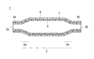
- FIG. 1 is a cross-sectional view of an example of a structure formed of a three-layered film body in which a balloon according to the present invention is sequentially laminated in the order of an outer layer 8, an intermediate layer 7, and an inner layer 6, and is merely an example of a balloon.
- the scope of the present invention is not limited to this.
- the balloon 1 according to the present invention is preferably used for a catheter.
- the balloon 1 is a tubular membrane body 2 that can be expanded and contracted by a fluid supplied from the catheter, and the axial direction of the membrane body. It is preferable that it is comprised from the connection parts 4a and 4b extended from both ends and connecting with the said catheter. In addition, openings 3a and 3b that are inserted from the catheter are formed in the connecting portions 4a and 4b at both ends. It is preferable that the opening part 3b of one connection part is formed larger diameter than the opening part 3a of the other connection part.
- the balloon 1 has a cylindrical portion having a substantially uniform outer diameter for expanding a narrowed portion of a body lumen such as a blood vessel, a ureter, and a bile duct.
- both ends of the cylindrical film-shaped main body may be tapered (tapered) as shown in FIG. Therefore, the balloon according to the present invention is connected to each of the cylindrical membrane-like main body having the tapered portions 5a and 5b having both ends tapered, and the tapered portions 5a and 5b, and the axial direction. It is preferable to have the connection parts 4a and 4b with the catheter extended outward. Furthermore, openings 3a and 3b that are inserted from the catheters are formed in the connecting portions at both ends.
- the central portion of the cylindrical membrane-shaped body is a portion where the maximum diameter portion of the balloon continues, and the tapered portions 5a and 5b are It is a portion that is continuous with the central portion of the cylindrical membrane-like main body and has a diameter that continuously changes toward the end.
- the connecting portions 4a and 4b to the catheter are portions that are continuous with the tapered portions 5a and 5b, respectively, and are small diameter portions having substantially the same inner diameter, and are portions that serve as attachment portions of the balloon to the catheter. Openings 3a and 3b are respectively formed.
- the taper portions 5a and 5b and the catheter connection portions 4a and 4b are provided on both sides of the tubular membrane body of the balloon, and the shapes of the respective taper portions and the respective connection portions may be different.
- the size of the balloon according to the present invention is such that the outer diameter of the tubular membrane body when expanded by nominal pressure is 1 to 6 mm, preferably 1.25 to 5.0 mm.
- the length of the membranous body in the major axis direction is 5 to 40 mm, preferably 5 to 35 mm.
- the entire length of the balloon (the total length in the major axis direction of the tubular membranous body and the connecting portion) ) Is 8 to 50 mm, preferably 10 to 45 mm.
- the cross-sectional shape perpendicular to the axis of the balloon according to the present invention is not particularly limited, and may be a circle, an ellipse, a substantially ellipse, or a polygonal column.
- the average film thickness when the balloon according to the present invention is deflated is preferably 10 to 50 ⁇ m, and more preferably 10 to 40 ⁇ m.
- the average film thickness when the balloon is deflated is preferably in the range of 10 to 50 ⁇ m from the viewpoint of trackability and permeability to stenotic sites such as blood vessels and body cavities.
- the balloon of the present invention is formed from a film in which three layers are laminated, the connection portions with the catheters formed at both ends of the membrane-like body 2 as shown in FIG. Even if it is integrated with the membrane-shaped main body 2 (integrated molding), it may be obtained by joining a substantially cylindrical membrane having a smaller diameter than the cylindrical membrane-shaped main body 2 separately. Therefore, the normal average film thickness of the connection part according to the present invention is preferably 20 to 200 ⁇ m, more preferably 20 to 180 ⁇ m.
- the balloon according to the present invention has a membrane-like main body that can be expanded and contracted by a fluid supplied from the catheter, the balloon is foldable. In the contracted state, the balloon is folded on the outer periphery of the main body tube of the catheter. What can be preferred.
- the surface of the outer layer and / or inner layer according to the present invention may be coated with a biocompatible material or an antithrombotic material as necessary.
- a biocompatible material or antithrombotic material various known polymers can be used alone or in combination.
- natural polymers collagen, gelatin, chitin, chitosan, cellulose, polyaspartic acid , Polyglutamic acid, polylysine, casein, etc.
- synthetic polymer phospholipid polymer, MPC (methacryloyloxyethyl phosphorylcholine) block polymer having a phosphate group in the side chain, polyhydroxyethyl methacrylate, hydroxyethyl methacrylate and styrene Copolymers (for example, HEMA-St-HEMA block copolymer), polymethyl methacrylate, polylactic acid, polyglycolic acid, lactic acid-glycolic acid copolymer, polyethylene, polypropylene, etc. can be preferably used
- the catheter balloon is made to exhibit lubricity when it comes into contact with blood or the like on the outer surface of the balloon or membranous body. It is preferable to perform the process for this.
- examples of such treatment include poly (2-hydroxyethyl methacrylate), polyhydroxyethyl acrylate, hydroxypropyl cellulose, methyl vinyl ether maleic anhydride copolymer, polyethylene glycol, polyacrylamide, polyvinyl pyrrolidone, dimethylacrylamide-glycidyl methacrylate.
- examples thereof include surface coating with a hydrophilic resin such as a random or block copolymer of acrylate, or a method of fixing to a surface.
- the outer layer and the inner layer are preferably formed in close contact with the surface of the intermediate layer, and the outer layer and the inner layer are preferably formed in close contact over the entire surface of the intermediate layer.
- the inner layer, the outer layer, and the intermediate layer which are components of the balloon according to the present invention, will be described.
- the intermediate layer according to the present invention is made of a non-elastomer and is 30% to 70% of the average film thickness of the entire balloon. That is, the region between the outer layer and the inner layer is an intermediate layer made of a non-elastomer that contributes to pressure resistance, and in the cross section obtained by cutting the central portion of the balloon according to the present invention in the direction perpendicular to the axis, Assuming an axis where the position (inner surface of the inner layer) is 0 and the position of the outer surface of the balloon (outer surface of the outer layer) is 1 outward in the radial direction, 0.1 or 0.
- the stretching pressure is easily applied, and in the region 0.5 or 0.8 from the outer surface (1), the stretching pressure is difficult to be applied. Therefore, the inner layer is a region from the inner surface (0) to 0.1 or 0.2, the outer layer is from 0.5 or 0.8 to the outer surface (1), and the remaining region (preferably 0.1 to 0). .8, more preferably 0.2 to 0.5) is preferred as the intermediate layer.
- the region occupied by the intermediate layer may be changed according to the required burst resistance and passage performance.
- the average thickness of the intermediate layer in the membranous body constituting the balloon according to the present invention is preferably 5 to 20 ⁇ m.
- the thickness of the intermediate layer may be set to an appropriate thickness from the balloon diameter, necessary burst resistance, and passability.
- the method for measuring the average thickness of the intermediate layer in the membranous body constituting the balloon according to the present invention is calculated by converting from the design dimensions of the original tube and the film thickness of the balloon.
- the intermediate layer according to the present invention is made of a non-elastomer
- the intermediate layer according to the present invention does not contain an elastomer
- the intermediate layer is preferably made of polyamide. That is, the intermediate layer according to the present invention preferably has a polyamide, and may contain a known additive or a contrast agent such as X-rays if necessary, or may be composed of only a polyamide. If the layer contains 1 to 100% by weight of polyamide, the pressure strength and compliance required for the catheter balloon can be ensured.
- the polyamide that can be suitably used in the intermediate layer according to the present invention is not particularly limited as long as it has an acid amide bond (—CO—NH—) in the main chain, and is usually a lactam or amino acid having a ring structure. It is produced by polymerization (homopolymerization) or condensation polymerization of dicarboxylic acid and diamine. Therefore, it is preferable to use homopolyamide as this polyamide.
- Monomers that can be polymerized alone include ⁇ -caprolactam, aminocaproic acid, enanthractam, 7-aminoheptanoic acid, 11-aminoundecanoic acid, 12-aminododecanoic acid, 9-aminononanoic acid, piperidone, and the like.
- examples of the dicarboxylic acid in the case of polycondensation of dicarboxylic acid and diamine include adipic acid, sebacic acid, dodecanedicarboxylic acid, glutaric acid, terephthalic acid, 2-methylterephthalic acid, isophthalic acid, naphthalenedicarboxylic acid and the like.
- examples of the diamine include tetramethylene diamine, hexamethylene diamine, nonamethylene diamine, decamethylene diamine, undecamethylene diamine, dodecamethylene diamine, paraphenylene diamine, and metaphenylene diamine.
- nylon 4 6, 7, 8, 11, 12, 6.6, 6.9, 6.10, 6.11, 6.12, 6T, 6 / 6.6, 6 / 12, 6 / 6T, 6T / 6I and the like.
- the terminal of polyamide may be sealed with a carboxyl group, an amino group, or the like.
- the said polyamide resin can be used individually by 1 type or in combination of 2 or more types.
- the polyamide according to the present invention is particularly preferably nylon 11 or nylon 12 among the above.
- the weight average molecular weight of the polyamide according to the present invention is preferably 2.0 ⁇ 10 4 to 5.0 ⁇ 10 4 , more preferably 3.0 ⁇ 10 4 to 5.0 ⁇ 10 4 , More preferably, it is 4.0 ⁇ 10 4 to 5.0 ⁇ 10 4 .
- the weight average molecular weight of the polyamide according to the present invention can be measured by a known method such as mass spectrometry, light scattering, liquid chromatography, gas chromatography, etc.
- gel permeation chromatography Is the molecular weight measured by
- additives contained in the intermediate layer as necessary include higher alcohols, hydroxybenzoic acid esters, and aromatic sulfonamides, but are not necessarily limited thereto.
- the additive contained in the intermediate layer as necessary is not particularly limited as long as it is opaque to radiation, and a known radiopaque substance can be used.
- a known radiopaque substance can be used.
- iodine, barium, bismuth, boron, bromine, calcium, gold, platinum, silver, iron, manganese, nickel, gadolinium, dysprosium, tungsten, tantalum, and these compounds such as barium sulfate, and solutions thereof / Dispersion (eg, saline); amidotrizoic acid (3,5-diacetamino-2,4,6-triiodobenzoic acid), sodium amidotrizoate meglumine, amidotrizoic acid meglumine, sodium iotaramate, meglumine iotaramate, Meglumine iotroxate, iotrolan, ioxagric acid, ioxirane, iopamidol, iopromide,
- the cross-sectional area ratio of the intermediate layer is preferably 30 to 70%, more preferably 35 to 60%.
- the outer layer according to the present invention includes an elastomer. Further, the outer layer containing the elastomer only needs to contain 1 to 100% by weight of the elastomer, and may contain a known additive or a contrast agent such as X-rays if necessary, or may be composed only of the elastomer. .
- the outer layer When an outer layer containing an elastomer is formed on the outermost layer, when the balloon is attached to the catheter and inserted into the body, the outer layer is flexible and thus has excellent permeability in blood vessels or body cavities.
- the average thickness of the outer layer in the membranous body constituting the balloon according to the present invention is preferably 5 to 15 ⁇ m, more preferably 5 to 10 ⁇ m.
- the average thickness is in the range of 5 to 15 ⁇ m, scratch resistance with hard components such as calcified lesions can be improved, and the procedure can be applied more safely.
- the material of the outer layer according to the present invention may be the same as the material of the inner layer according to the present invention, and the elastomer of the outer layer according to the present invention and the elastomer of the inner layer according to the present invention may be the same.
- the elastomer contained in the outer layer according to the present invention is preferably a polyamide elastomer having sufficient adhesiveness with the polyamide of the intermediate layer so as not to cause delamination.
- the polyamide elastomer is preferably a polyamide block copolymer, more preferably a binary block copolymer having a hard segment and a soft segment.
- a binary block copolymer for example, a block polymer of polyamide (hard segment) and polyether (soft segment), specifically, a block copolymer of nylon 11 and polytetramethylene glycol, nylon 12 and poly Examples include block copolymers of tetramethylene glycol.
- the Shore D hardness of the polyamide elastomer according to the present invention is preferably 40 to 75, more preferably 55 to 65.
- the tensile elastic modulus of the polyamide elastomer according to the present invention is preferably 100 to 500 MPa, more preferably 100 to 250 MPa. By using a more flexible polyamide elastomer, improvement in passability can be expected.
- the polyamide elastomer according to the present invention preferably has a block copolymer represented by the following chemical formula (1) or chemical formula (2) in the polymer chain.
- a is an integer of 4 to 12
- b is an integer of 4 to 10
- c is an integer of 0 to 100
- d is an integer of 0 to 100
- p is an integer of 2 to 4
- Ln is a linker moiety, —C (O) —R—O—C (O) —, and R is an alkylene group having a methylene number of 2 to 12 is there.
- n is an integer of 5 to 11
- l is an integer of 0 to 100
- m is an integer of 1 to 100
- p is an integer of 2 to 4
- q is an integer of 1 to 100.
- Ln is a linker moiety and is —C (O) —R—O—C (O) —, wherein R is an alkylene group having a methylene number of 2 to 12. That is, the polyamide elastomer according to the present invention may be the polyamide block copolymer of the above chemical formula (1) or the chemical formula (2), or the polyamide block copolymer of the above chemical formula (1) or the chemical formula (2).
- the polyamide elastomer according to the present invention may be further polymerized by melt polymerization of the polyamide block copolymer represented by the chemical formula (1) or (2). Is preferred. Therefore, when the polymer is further polymerized by melt polymerization, the polyamide block copolymer represented by the chemical formula (1) or (2) becomes a “repeating unit”.
- the R may be linear, branched or cyclic as an alkylene group having a methylene number of 2 to 12.
- specific examples include tetramethylene group, 2-methylpropylene group, 1,1-dimethylethylene group, n-pentylene group, n-hexylene group, n-nonylene group, 1-methyloctylene group, 6-methyloctylene group, 1-ethylheptylene group, 1- (n-butyl) pentylene group, 4-methyl-1- (n-propyl) pentylene group, 1,5,5-trimethylhexylene group, 1,1 , 5-trimethylhexylene group, n-decylene group, 1-methylnonylene group, 1-ethyloctylene group, 1- (n-butyl) hexylene group, 1,1-dimethyloctylene group, 3,7-dimethyl group
- examples thereof include a tiloctylene group, an
- the polymer when the polymer is further polymerized, it can be obtained by melt polymerization of the polyamide elastomer whose both ends are not sealed.
- the melt polymerization is performed using a vacuum dryer (VEL301SD manufactured by EYELA) equipped with a cooling function (cooler: UTELA manufactured by EYELA) for a certain period of time (12 to 72 hours) with a vacuum pump (GCD136XN manufactured by ULVAC). It can be carried out by heating at 220 to 250 ° C.
- the polyamide block copolymer represented by the chemical formula (1) or the chemical formula (2) is used for the outer layer according to the present invention
- the polyamide block copolymer represented by the chemical formula (1) or the chemical formula (2) is used. You may use individually by 1 type or in combination of 2 types.
- the polyamide elastomer according to the present invention may be synthesized or purchased commercially, and as the polyamide elastomer that can be used in the present invention, ELG5660 (manufactured by EMS, trade name: Grilflex ELG5660), ELG6260 (manufactured by EMS, Product name: Grilflex ELG6260), high molecular weight polymer obtained by melt polymerization of ELG5660 (melt viscosity 1260-3289 Pa ⁇ s), high molecular weight polymer obtained by melt polymerization of ELG6260 (melt viscosity 5282-7391 Pa ⁇ s), and the like.
- ELG5660 manufactured by EMS, trade name: Grilflex ELG5660
- ELG6260 manufactured by EMS, Product name: Grilflex ELG6260
- high molecular weight polymer obtained by melt polymerization of ELG5660 melt viscosity 1260-3289 Pa ⁇ s
- end of the polyamide elastomer according to the present invention may be sealed with a carboxyl group, an amino group, or the like.
- the melt viscosity of the polyamide elastomer according to the present invention is preferably 500 or more, more preferably 500 to 20000 Pa ⁇ s. This is because elongation due to pressurization is further suppressed, and the entire balloon exhibits lower compliance.
- the melt viscosity was measured using a flotester “Shimadzu CFT-500D”.
- the cross-sectional area ratio of the outer layer is preferably 20 to 50%, more preferably 25 to 50%.
- the inner layer according to the present invention contains an elastomer.
- the inner layer containing the elastomer may contain 1 to 100% by weight of the elastomer, and may contain a known additive or a contrast agent such as X-rays if necessary, or may be composed only of the elastomer. .
- a catheter balloon exhibiting stable pressure resistance can be provided, and flexibility can be imparted to the entire balloon, so that it is excellent in passage through blood vessels or body cavities.
- the average thickness of the inner layer in the membranous body constituting the balloon according to the present invention is preferably 0.1 to 10 ⁇ m, more preferably 0.1 to 7 ⁇ m.
- An average thickness in the range of 0.1 to 10 ⁇ m is preferable because the balance between flexibility of the entire balloon and low compliance characteristics can be achieved.
- the elastomer contained in the inner layer according to the present invention is preferably a polyamide elastomer that has good adhesion to the intermediate layer and does not cause delamination.
- the polyamide elastomer contained in the inner layer according to the present invention can use the same material as the polyamide elastomer in the outer layer, description of the polyamide elastomer is omitted here.
- a preferred embodiment of the balloon according to the present invention is such that an inner layer made of polyamide elastomer is provided on the innermost side, an intermediate layer made of polyamide is laminated on the surface of the inner layer, and outside the intermediate layer Further, it is preferably formed from a film-like main body provided with an outer layer made of polyamide elastomer.
- the method for producing a balloon of the present invention comprises a step of forming a three-layer polymer tube (parison) in which an intermediate layer is made of a non-elastomer and an inner layer and an outer layer are made of an elastomer by co-extrusion by a conventional wire coating method (1) ), And the parison is stretched in the axial direction at a temperature ranging from the secondary transition temperature to the primary transition temperature of both polymers, and the stretched parison is radially expanded to be biaxially stretched (2) ), And the expanded parison is cooled below the second transition temperature of both polymers, and the cooled parison is contracted to form a cylindrical film-like body having a substantially uniform inner diameter, respectively, before and after the film-like body.
- Step (3) of forming a biaxially stretched balloon having a tapered portion provided, and a connecting portion with a catheter provided before and after the tapered portion, and if necessary, biaxially stretched After re-stretching the taper portion of the rune to reduce the thickness of the taper portion, inflating the re-stretched balloon and maintaining the inflated state, the balloon is heated above the secondary transition temperature of the polymer, and then the balloon It is preferable to include a step (4) of cooling to a temperature not higher than the second order transition temperature of the polymer.
- each layer constituting the balloon membrane attention is paid to the thickness of each layer constituting the balloon membrane.
- the pressure the radial direction and the axial direction of the balloon
- Due to the deviation the pressure resistance of the balloon itself as a product and the variation in pressure resistance among products were confirmed.
- the compliance characteristics of the balloon, the bursting pressure of the balloon, or the flexibility of the balloon may be impaired. It has been confirmed.
- the blowing temperature is 70 to 100 ° C.
- the annealing temperature is 100 to 130 ° C.
- the blowing and annealing pressure is 3.0 to 4.5 MPa
- the radial draw ratio. 6 to 9 times, and the axial draw ratio to 2 to 4 times a balloon having a film-like body in which each layer has a film thickness in a desired range can be manufactured, resulting in compliance characteristics, A balloon excellent in flexibility or bursting pressure can be provided.
- the inner layer, the outer layer and the intermediate layer are preferably made of the same material.
- all are polyamide-based materials, but all may be polyurethane-based materials such as an intermediate layer made of polyurethane non-elastomer and inner and outer layers made of polyurethane-based elastomer.
- polyurethane-based materials such as an intermediate layer made of polyurethane non-elastomer and inner and outer layers made of polyurethane-based elastomer.
- the step (1) of forming a tubular parison (hereinafter also referred to as a tube or a parison) from a stretchable polymer can be performed by a general-purpose extruder equipped with a die.
- An elastomer is used as the material for the outer layer and the inner layer, and a non-elastomer is used as the material for the intermediate layer.
- Each of the molding polymers was heated and melted at 150 to 270 ° C. in an extruder so that the elastomer would be 40 to 240 parts by weight with respect to 100 parts by weight of the non-elastomer, and the polymer was coextruded from a die, and the parison 27 is formed.
- the film thickness of the final intermediate layer of the balloon molded product is determined.
- the extrusion temperature at this time is not particularly limited as long as the polymer can be melted, but is preferably 160 to 260 ° C, more preferably 170 to 260 ° C, and the extrusion pressure is 0.5 to 10 ° C. 0.0 MPa.
- the step (2) of biaxial stretching by expanding the parison in the radial direction can be performed using a balloon molding die.
- this tubular parison 27 is inserted into the mold 20 shown in FIG. 2 as an example, and one end of the tube 27 is closed.
- the blockage is performed using heat melting, high frequency sealing, forceps and the like.
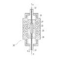
- FIG. 2 is a cross-sectional view of the balloon mold 20.
- the mold 20 includes a heater 22 that is a heating means and a cooling pipe 23 that is a cooling means.
- die 20 becomes the separation molds 25 and 26, and the inner surface shape formed when the separation molds 25 and 26 are combined is the basic outer surface shape of the balloon to be formed.
- the heater 22 is operated, and the tube 27 in the portion forming the balloon 1 is in the range of the glass transition temperature of 30 to 60 ° C. of the polymer (non-elastomeric and elastomer forming the tube 27).
- a temperature slightly above 70 to 100 ° C.
- a portion that is heated in the mold 20 by maintaining the tube 27 in a heated state, extending the tube 27 in the directions of the arrows X and Y, and further sending gas from the arrow Z direction while pressurizing the gas into the tube 27.
- the tube 27 is brought into close contact with the inner wall surfaces of the separation molds 25 and 26.
- the draw ratio is preferably 6 to 9 times in the direction perpendicular to the axis of the balloon (balloon radial direction) and 2 to 4 times in the axial direction (longitudinal direction of the balloon axis).
- the degree of the stretching distance in the XY direction is determined by the pressure applied from the Z direction at this time. If the internal pressure is too low, the balloon cannot be formed unless the stretching distance is extended. If the internal pressure is too high, the balloon is formed before the axial stretching. It is desirable to apply pressure to the inside of the tube so that the stretching distance in the axial direction is within the above-described stretching ratio.
- Step (3) Step (3) of forming a balloon having a tubular membrane, a tapered portion provided before and after the membrane, and a connecting portion connected to a catheter provided before and after the tapered portion.
- the cooling liquid is circulated in the cooling pipe 23 to cool the tube 27 to the second transition temperature or lower.
- this cooling may be performed by simply leaving it alone without circulating the coolant.
- the inside of the tube 27 is brought to normal pressure, and the tube 27 is removed from the mold 20.
- the basic shape of the balloon as shown in FIG. 1 is formed by cutting the tube 27 at the front end portion and the rear end portion of the tube 27.
- the taper portions 5a and 5b of the biaxially stretched balloon are re-stretched to reduce the thickness of the tapered portion, the re-stretched balloon is inflated, and while maintaining the inflated state, the above Similarly to step (2), after the balloon is heated to a temperature equal to or higher than the second transition temperature of the polymer, the balloon may be cooled to a temperature equal to or lower than the second transition temperature of the polymer.
- the balloon catheter according to the present invention has an inner tube having a first lumen that is open at the tip, and is provided coaxially with the inner tube and has a tip at a position retracted by a predetermined length from the tip of the inner tube.
- An outer tube forming a second lumen with the outer surface of the inner tube; a distal end portion is fixed to the inner tube; a proximal end portion is fixed to the outer tube; and an inner portion is connected to the second lumen
- a balloon catheter for vasodilation comprising a collapsible foldable balloon, which is preferably the balloon according to the present invention.
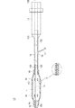
- FIG. 3 is a schematic view showing an example of a balloon catheter according to the present invention.
- the balloon catheter 10 is coaxially provided with the inner tube 14 having a first lumen 150 having an open distal end and a position retracted from the distal end of the inner tube 14 to a proximal end side by a predetermined length.
- the outer tube 12 that forms the second lumen 120 between the outer surface of the inner tube 14 and the catheter connection portion (the balloon distal end side) 4a, and the catheter connection portion (the balloon proximal end portion).
- Side) 4b the connecting portion 4b is attached to the outer tube 12, the connecting portion 4a is attached to the inner tube 14, and the foldable balloon 1 communicating with the second lumen 120 in the vicinity of the proximal end portion; It has.
- the balloon catheter 10 preferably also includes a hub 13 having an opening communicating with the second lumen. Further, the balloon 1 covers the vicinity of the proximal end portion of the outer tube 12, and the interior 112 of the balloon 1 communicates with the second lumen 120.
- FIG. 3 which is one form of the balloon catheter 10 of the present invention, a catheter body 101 having a long outer tube 12 capable of transferring a fluid, a balloon 1 connected to the distal end of the catheter body 101, and a catheter body And a hub 13 attached to the proximal end of 101.
- the balloon catheter 10 includes an inner tube 14 that passes through the second lumen 120 formed in the outer tube 12, and a distal end member 15 that is provided at the distal end of the inner tube 14.
- the distal end is an end portion (proximal end) located on the side to be inserted into the blood vessel in use, and the proximal end is an end portion located on the side of the operator who operates the balloon catheter 10 in use ( Distal end).
- FIG. 3 shows a rapid exchange type catheter having a single lumen on the proximal end side of the catheter and a wire port into which a guide wire can be inserted between the distal end and the proximal end.
- An over-the-wire type in which the end side is a coaxial double lumen and the inner tube extends to the hub may be used.
- This balloon catheter 10 is an example applied to a vasodilator catheter, and the balloon and balloon catheter of the present invention can also be applied to other catheters such as a urinary catheter.
- Examples of the fluid supplied from the catheter to the balloon include known ones such as a contrast medium, helium gas, physiological saline, CO 2 gas, O 2 gas, N 2 gas, and air.
- the balloon catheter 10 of the present invention includes a catheter main body 101 having an inner tube 14 and an outer tube 12, a hub 13, and a balloon 1.
- the inner tube 14 has a first lumen 150 (inner outer lumen) whose tip is open.
- the first lumen 150 is a lumen for inserting a guide wire, and communicates with the wire port 18 that is an opening that forms a guide wire port.
- the guide wire 17 can be inserted through the wire port 18.
- the inner tube 14 has an outer diameter of 0.30 to 2.50 mm, preferably 0.40 to 2.00 mm, and an inner diameter of 0.20 to 2.35 mm, preferably 0.25 to 1.70 mm. .
- a material for forming the inner tube 24 a material having a certain degree of flexibility is preferable.
- polyolefin such as polyethylene, polypropylene, ethylene-propylene copolymer, ethylene-vinyl acetate copolymer, polyvinyl chloride, polyurethane, Thermoplastic resins such as polyamide, polyamide elastomer, and polyester elastomer can be used.
- the outer tube 12 is inserted in the inner tube 14 and provided at a position where the tip is slightly retracted from the tip of the inner tube.
- the second lumen 120 is formed by the inner surface of the outer tube 12 and the outer surface of the inner tube 14. Is formed. Therefore, the second lumen 120 can be a lumen having a sufficient volume.
- the second lumen 120 communicates at the tip thereof with the inside of the balloon 1 and the rear end thereof, and the rear end of the second lumen 120 is a fluid for inflating the balloon (for example, contrast medium, helium gas). , Physiological saline, CO 2 gas, O 2 gas, etc.) are communicated with the opening 130 of the hub 13 that forms an injection port for injecting.
- the outer tube 12 has an outer diameter of 0.50 to 4.30 mm, preferably 0.60 to 4.00 mm, and an inner diameter of 0.40 to 3.80 mm, preferably 0.50 to 3.00 mm. .
- the above radiopaque material may be injected into the balloon when the balloon is expanded.
- a material having a certain degree of flexibility is preferable.
- polyolefin such as polyethylene, polypropylene, ethylene-propylene copolymer, ethylene-vinyl acetate copolymer, polyvinyl chloride, polyurethane, Thermoplastic resins such as polyamide, polyamide elastomer, and polyester elastomer can be used.
- the tip of the balloon catheter 10 of the present invention has a spherical tip member 15 in order to help follow the blood vessel and prevent damage to the blood vessel wall. Is preferred.
- the balloon 1 is foldable and can be folded on the outer periphery of the inner tube 14 when not expanded.
- the balloon 1 is foldable and has a substantially cylindrical body having the same diameter, at least part of which is cylindrical so that a stenosis of a blood vessel or body cavity can be easily expanded.
- the balloon 11 has its connecting portion 4b fixed to the distal end portion of the outer tube 12 in a liquid-tight manner by an adhesive or heat fusion.
- the connecting portion 4a is fixed to the distal end portion of the inner tube 14 in a liquid-tight manner.
- the balloon 1 forms a space 112 between the inner surface of the balloon 1 and the outer surface of the inner tube 14 when expanded.
- the second lumen 120 communicates with the entire circumference thereof.
- the balloon 1 is comprised from the film
- the X-ray marker 44 is positioned near the rear end side of the balloon 1 to the inner tube 14, and near the front end side of the balloon 1 and the outer tube 12. It is preferable to provide it in the part located in the both ends of the cylindrical membranous main body 2 of the balloon 1.
- the X-ray marker 44 is preferably formed of an X-ray opaque material (for example, gold, platinum, iridium, tungsten, or an alloy thereof).
- the hub 13 has an opening 130 that communicates with the second lumen 120 and forms an injection port that is an inlet of a passage for injecting and discharging fluid. Therefore, the opening part 130 also plays a role as a flow path and communicates with a fluid supply / discharge part (not shown) such as an indeflator, a syringe, or a pump. As a result, the fluid is supplied to the balloon 1 through the opening 130 and the second lumen 120 or discharged from the balloon 1. That is, the opening 130 and the lumen 120 function as a supply and discharge path for the driving fluid that expands and contracts the balloon 1.
- a fluid supply / discharge part such as an indeflator, a syringe, or a pump.
- thermoplastic resins such as polycarbonate, polyamide, polysulfone, polyarylate, and methacrylate-butylene-styrene copolymer can be suitably used.
- Example 1 As an elastomer used for the inner layer and the outer layer, a polyamide elastomer (manufactured by EMS, trade name: Grilflex ELG5660) resin and a nylon 12 (trade name: MILAMIDL L25, manufactured by EMS) as an intermediate layer (inner diameter expansion ratio: 8 times, axial expansion ratio: 3 times, ⁇ 0.360 ⁇ 0.485 ⁇ 0.825 ⁇ 0.875 mm, each diameter ⁇ 0.03 mm) was co-extruded at 170-260 ° C.
- EMS polyamide elastomer
- MILAMIDL L25 manufactured by EMS
- blow molding is performed by blowing dry nitrogen into the obtained tube at a pressure of 3.8 MPa for a certain time at 90 ° C., and a balloon having an outer diameter (nominal diameter) of 3.00 mm, an average film thickness of 21 ⁇ m, and a length of 15 mm.
- the average film thickness of the intermediate layer was 14.5 ⁇ m, and the ratio of the intermediate layer was 70%.
- the average film thickness here means an arithmetic average at an arbitrary position (six points) of the balloon, and is measured using a Mitutoyo Digimatic Indicator.
- Example 2 Three-layer tube (inner diameter expansion ratio) using polyamide elastomer (trade name: Griflex ELG5660, manufactured by EMS) as an elastomer used for the inner layer and outer layer, and nylon 12 (trade name: Grilamid L25, manufactured by EMS) as an intermediate layer. 8 ⁇ , axial expansion ratio: 3 ⁇ , ⁇ 0.360 ⁇ 0.485 ⁇ 0.805 ⁇ 0.875 mm, each diameter ⁇ 0.03 mm) was coextruded at 170 to 260 ° C.
- polyamide elastomer trade name: Griflex ELG5660, manufactured by EMS
- nylon 12 trade name: Grilamid L25, manufactured by EMS
- blow molding is performed by blowing dry nitrogen into the obtained tube at a pressure of 3.8 MPa for a certain time at 90 ° C., and a balloon having an outer diameter (nominal diameter) of 3.00 mm, an average film thickness of 21 ⁇ m, and a length of 15 mm.
- the average film thickness of the intermediate layer measured by the same method as in Example 1 was 13.5 ⁇ m, and the ratio of the intermediate layer was 65%.
- Example 3 Three-layer tube (inner diameter expansion ratio) using polyamide elastomer (trade name: Griflex ELG5660, manufactured by EMS) as an elastomer used for the inner layer and outer layer, and nylon 12 (trade name: Grilamid L25, manufactured by EMS) as an intermediate layer. 8 ⁇ , axial expansion ratio: 3 ⁇ , ⁇ 0.360 ⁇ 0.485 ⁇ 0.785 ⁇ 0.875 mm, each diameter ⁇ 0.03 mm) was co-extruded at 170 to 260 ° C.
- polyamide elastomer trade name: Griflex ELG5660, manufactured by EMS
- nylon 12 trade name: Grilamid L25, manufactured by EMS
- blow molding is performed by blowing dry nitrogen into the obtained tube at a pressure of 3.8 MPa for a certain time at 90 ° C., and a balloon having an outer diameter (nominal diameter) of 3.00 mm, an average film thickness of 21 ⁇ m, and a length of 15 mm.
- the average film thickness of the intermediate layer measured by the same method as in Example 1 was 12.5 ⁇ m, and the ratio of the intermediate layer was 60%.
- Example 4 As an elastomer used for the inner layer and the outer layer, a polyamide elastomer (trade name: Griflex ELG5660, manufactured by EMS) resin, and nylon 12 (trade name: grilamid L25, manufactured by EMS) as an intermediate layer (inner diameter expansion ratio: 8 times, axial expansion magnification: 3 times, ⁇ 0.360 ⁇ 0.485 ⁇ 0.765 ⁇ 0.875 mm, each diameter ⁇ 0.03 mm) was molded at 170 to 260 ° C.
- a polyamide elastomer trade name: Griflex ELG5660, manufactured by EMS
- nylon 12 trade name: grilamid L25, manufactured by EMS
- blow molding is performed by blowing dry nitrogen into the obtained tube at a pressure of 3.8 MPa for a certain time at 90 ° C., and a balloon having an outer diameter (nominal diameter) of 3.00 mm, an average film thickness of 21 ⁇ m, and a length of 15 mm.
- the average film thickness of the intermediate layer measured by the same method as in Example 1 was 11.5 ⁇ m, and the ratio of the intermediate layer was 55%.
- Example 5 A three-layer tube (inner diameter expansion ratio: 8 times) using a polyamide elastomer (trade name: Griflex ELG5660 manufactured by EMS) as an elastomer used for the inner layer and the outer layer, and nylon 12 (trade name: Grilamid L25 manufactured by EMS) as an intermediate layer.
- blow molding is performed by blowing dry nitrogen into the obtained tube at a pressure of 3.8 MPa for a certain time at 90 ° C., and a balloon having an outer diameter (nominal diameter) of 3.00 mm, an average film thickness of 21 ⁇ m, and a length of 15 mm.
- the average film thickness of the intermediate layer measured by the same method as in Example 1 was 10.5 ⁇ m, and the ratio of the intermediate layer was 50%.
- Example 6 A three-layer tube (inner diameter expansion ratio: 8 times) using a polyamide elastomer (trade name: Griflex ELG5660 manufactured by EMS) as an elastomer used for the inner layer and the outer layer, and nylon 12 (trade name: Grilamid L25 manufactured by EMS) as an intermediate layer. , Axial expansion ratio: 3 times, ⁇ 0.360 ⁇ 0.485 ⁇ 0.675 ⁇ 0.875 mm, each diameter ⁇ 0.03 mm) was molded at 170 to 260 ° C.
- a polyamide elastomer trade name: Griflex ELG5660 manufactured by EMS
- nylon 12 trade name: Grilamid L25 manufactured by EMS
- blow molding is performed by blowing dry nitrogen into the obtained tube at a pressure of 3.8 MPa for a certain time at 90 ° C., and a balloon having an outer diameter (nominal diameter) of 3.00 mm, an average film thickness of 21 ⁇ m, and a length of 15 mm.
- the average film thickness of the intermediate layer measured by the same method as in Example 1 was 7.5 ⁇ m, and the ratio of the intermediate layer was 35%.
- Comparative Example 1 As a comparative example, a conventional two-layer balloon was used. The inner layer is made of polyamide and the outer layer is made of polyamide elastomer. The ratio of the film thickness of the inner layer made of polyamide to the total film thickness of the balloon is 84%.
- Comparative Example 2 As a comparative example, a conventional single-layer balloon was used. The material is a mixed material of polyamide elastomer.
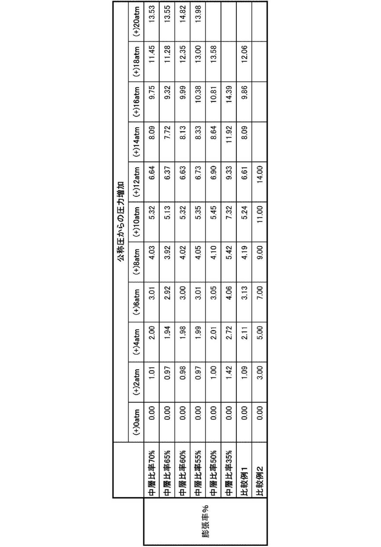
- the method of measuring the amount of change in diameter with respect to the pressurization includes a step of immersing a measurement sample in 37 ° C. warm water and reducing the desired internal pressure from 1 minute to 1 atm, as in the burst resistance measurement. The above cycle is repeated with the desired pressure being 1, 6, 8, 10,..., 20, 21,... Atm as follows, and the diameter under a specific pressure is measured.
- the expansion rate (%) under a specific pressure means a value obtained by subtracting the diameter at each nominal pressure from the diameter at each specific pressure of each balloon and then multiplying by 100 by the value divided by the diameter at the nominal pressure.
- Fig. 4 is a graph of Table 1.
- the balloons of Examples 1 to 6 and the balloon of Comparative Example 1 exhibited low compliance performance and burst resistance performance even at a high inflation pressure.
- the expansion ratio at nominal pressure + about 13 atm is 8% or less while the middle layer ratio is reduced.
- the nominal pressure + about 13 atm is also obtained.
- the expansion rate at 11 is 11% or less, realizing low compliance. As a result, it can be seen that there is expansion performance suitable for post-expansion of the stent.
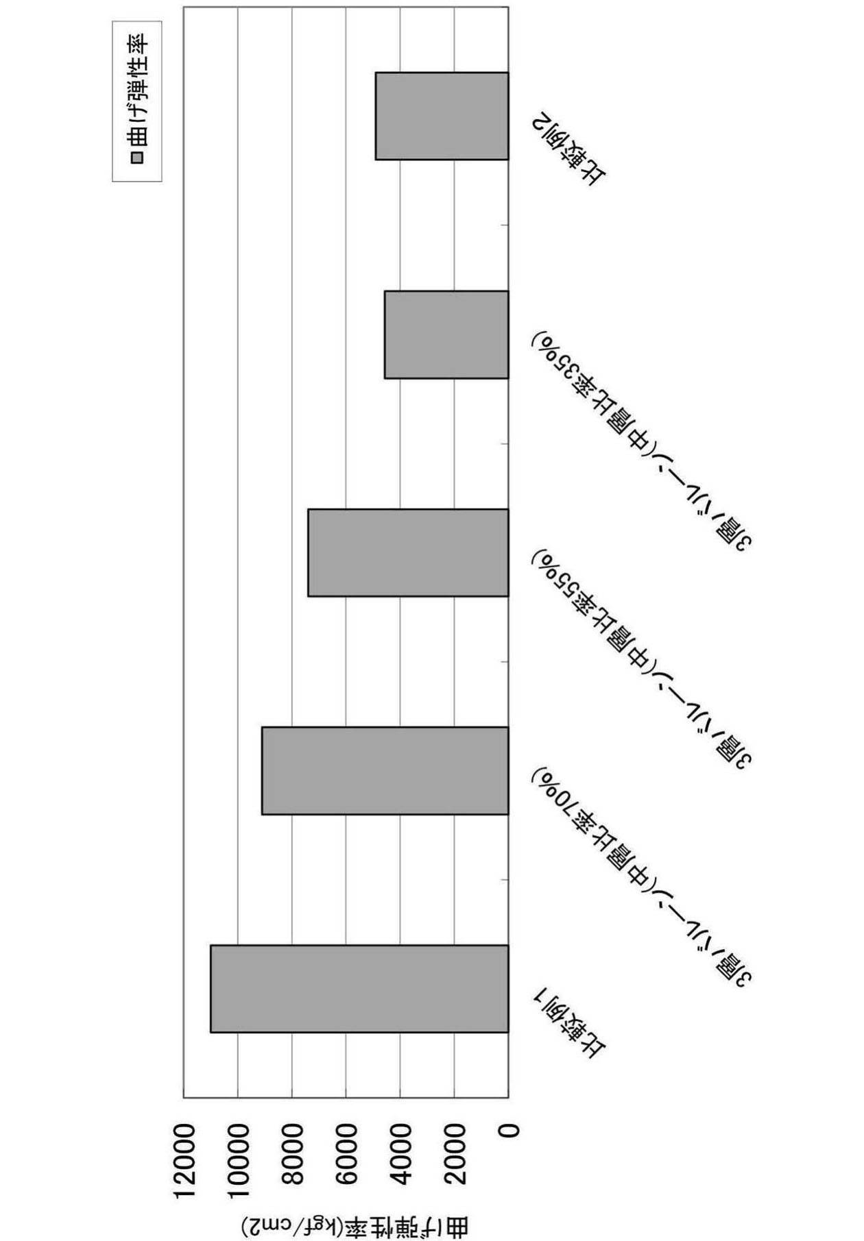
- the balloon obtained in the above example was subjected to a three-point bending flexural modulus measurement using a small desktop load tester (MODEL1305N) manufactured by Aiko Engineering.
- the sample holding interval was 25.4 mm
- the indentation length was 2 mm
- the indentation speed was 5 mm / min
- the flexural modulus (kgf / cm 2 ) of each of the balloons of Examples 1 to 6 and the balloon of the comparative example was calculated.
- the results are shown in Tables 2 and 3.
- Example 6 when the ratio of the average thickness of the intermediate layer according to the present invention is 35% to 70%, it belongs to the range of flexibility of the conventional balloon, and the permeability is good. It is believed that there is. In particular, it was confirmed that Example 6 in which the average thickness of the intermediate layer was 35% with respect to the entire thickness of the balloon of the present invention was particularly excellent in passage.
Landscapes
- Health & Medical Sciences (AREA)
- Life Sciences & Earth Sciences (AREA)
- Engineering & Computer Science (AREA)
- Heart & Thoracic Surgery (AREA)
- Public Health (AREA)
- Animal Behavior & Ethology (AREA)
- Veterinary Medicine (AREA)
- General Health & Medical Sciences (AREA)
- Manufacturing & Machinery (AREA)
- Child & Adolescent Psychology (AREA)
- Biophysics (AREA)
- Pulmonology (AREA)
- Anesthesiology (AREA)
- Biomedical Technology (AREA)
- Hematology (AREA)
- Chemical & Material Sciences (AREA)
- Epidemiology (AREA)
- Chemical Kinetics & Catalysis (AREA)
- Mechanical Engineering (AREA)
- Media Introduction/Drainage Providing Device (AREA)
- Materials For Medical Uses (AREA)
Description
本発明のバルーンは、耐圧性能と通過性能とを維持したまま加圧によるバルーン部の伸びを劇的に抑えることが可能となる。
図1は、本発明に係るバルーンが外層8、中間層7、および内層6の順で順次積層された3層の膜状本体から形成された構造の一例の断面図であり、あくまでもバルーンの一例であり本発明の範囲はこれに限定されることはない。
本発明に係る中間層は非エラストマーからなり、かつバルーンの全体の平均膜厚の30%~70%である。すなわち、外層と内層との間の領域を耐圧性に寄与する非エラストマーからなる中間層にするものであり、本発明に係るバルーンの中心部分を軸直角方向に切断した断面において、バルーン内表面の位置(内層の内表面)を0とし放射方向外方に向かってバルーン外表面の位置(外層の外表面)を1とする軸を想定した場合、内表面(0)から0.1または0.2の領域においては延伸圧がかかりやすい領域であり、外表面(1)から0.5または0.8の領域においては延伸圧がかかりにくい領域である。そのため、内層は内表面(0)から0.1または0.2の領域とし、外層は0.5又は0.8から外表面(1)までとし、残りの領域(好ましくは0.1~0.8、より好ましくは0.2~0.5)を中間層とすることが好ましい。この中間層が占める領域は、必要とする耐破裂性能と通過性能に合わせて変更してもよい。
本発明に係る外層はエラストマーを含む。また、エラストマーを含有する外層とは、エラストマーが1~100重量%含んでいればよく、必要により公知の添加剤やX線等の造影剤を含んでもよく、またはエラストマーのみから構成されてもよい。


すなわち、本発明に係るポリアミドエラストマーは、上記の化学式(1)もしくは化学式(2)のポリアミドブロック共重合体自体であっても、上記の化学式(1)もしくは化学式(2)のポリアミドブロック共重合体を溶融重合によりさらに高分子化したものであってもよいが、本発明に係るポリアミドエラストマーは、上記の化学式(1)もしくは化学式(2)のポリアミドブロック共重合体を溶融重合によりさらに高分子化したものが好ましい。したがって溶融重合によりさらに高分子化した場合、上記の化学式(1)もしくは化学式(2)のポリアミドブロック共重合体がいわば“繰り返し単位”となる。
本発明に係る内層はエラストマーを含む。また、エラストマーを含有する内層とは、エラストマーが1~100重量%含んでいればよく、必要により公知の添加剤やX線等の造影剤を含んでもよく、またはエラストマーのみから構成されてもよい。
以下、本発明に係るバルーンの製造方法の好ましい実施形態について説明する。本発明のバルーンの製造方法は、常法の電線被覆法による共押出を行い、中間層が非エラストマーからなり、内層および外層がエラストマーからなる三層のポリマーチューブ(パリソン)を形成する工程(1)と、当該パリソンを両ポリマーの二次転移温度から一次転移温度までの範囲の温度下にて軸方向に延伸し、さらに延伸されたパリソンを半径方向に膨張させて二軸延伸する工程(2)と、膨張されたパリソンを両ポリマーの二次転移温度以下に冷却し、さらに冷却されたパリソンを収縮させて、内径がほぼ均一な筒状の膜状体、該膜状体の前後にそれぞれ設けられたテーパー部、および前記テーパー部の前後に設けられたカテーテルとの接続部を有する二軸延伸されたバルーンを形成する工程(3)と、必要により、二軸延伸されたバルーンのテーパー部を再延伸してテーパー部の肉厚を薄肉化し、当該再延伸されたバルーンを膨張させ、膨張状態を維持しながら、バルーンをポリマーの二次転移温度以上に加熱した後、バルーンをポリマーの二次転移温度以下の温度にまで冷却させる工程(4)と、を含むことが好ましい。
延伸可能なポリマーによりチューブ状パリソン(以下、チューブまたはパリソンとも称する)を形成する工程(1)は、ダイスを取り付けた汎用の押出成形機によって行うことができる。外層および内層の材料としてエラストマー、ならびに中間層の材料として非エラストマーを成形用ポリマーとする。当該成形用のポリマーをそれぞれ、非エラストマー100重量部に対してエラストマーを40~240重量部となるよう押出成形機内にて150~270℃で加熱溶融し、ダイスより前記ポリマーを共押出して、パリソン27を成形する。この非エラストマー層にあたる中間層と、エラストマー層にあたる内層、外層の比率を制御することで最終的なバルーン成形物の中間層の膜厚が決定される。このときの押出成形温度は、前記ポリマーが溶融可能な温度であれば、特に制限はないが、好ましくは160~260℃、より好ましくは170~260℃であり、押出圧力が0.5~10.0MPaである。
パリソンを半径方向に膨張させて二軸延伸する工程(2)は、バルーン成形金型を用いて行うことができる。具体的には、このチューブ状パリソン27を、一例である図2に示す金型20内に挿入し、チューブ27の一端を閉塞する。閉塞は、加熱溶融、高周波によるシール、鉗子などを用いて行う。図2は、バルーン成形金型20の断面図である。この金型20は、加温手段であるヒーター22と冷却手段である冷却管23とを有している。そして、金型20は分離型25,26となっており、分離型25,26を組み合わせた際に形成される内面形状が、形成するバルーンの基本外面形状となっている。
筒状の膜状体と、該膜状体の前後にそれぞれ設けられたテーパー部と、前記テーパー部の前後に設けられたカテーテルと接続する接続部と、を有するバルーンを形成する工程(3)は、延伸処理により形成される。具体的には、冷却管23内に冷却液を循環して、チューブ27を二次転移温度以下に冷却する。また、この冷却は、冷却液を循環することなく、単に放置して自然冷却してもよい。その後チューブ27内部を常圧にし、金型20内より、チューブ27を抜去する。そして、チューブ27の先端部および後端部にてチューブ27を切断することにより、図1に示すようなバルーンの基本形状が形成される。また、上記延伸処理を2回以上行うことによって、目的とする肉厚のバルーンを形成してもよい。
バルーンを再延伸して肉厚を薄肉化し、バルーンをポリマーの二次転移温度以上に加熱した後、バルーンをポリマーの二次転移温度以下の温度にまで冷却させる工程(4)を必要により上記工程(3)の後に設けてもよい。
本発明に係るバルーンカテーテルは、先端が開口している第1のルーメンを有する内管と、前記内管に同軸的に設けられ、前記内管の先端より所定長後退した位置に先端を有し、前記内管の外面との間に第2のルーメンを形成する外管と、先端部が前記内管に固定され、基端部が前記外管に固定され、内部が前記第2のルーメンと連通する折り畳み可能なバルーンと、を備える血管拡張用バルーンカテーテルであって、当該バルーンは本発明に係るバルーンであることが好ましい。
「バルーンの作製」
(実施例1)
内層および外層に使用するエラストマーとして、ポリアミドエラストマー(EMS社製、商品名:GrilflexELG5660、)樹脂、および中間層としてナイロン12(EMS社製 商品名:GrilamidL25)を用いた3層チューブ(内径拡張倍率:8倍、軸方向拡張倍率:3倍、φ0.360×0.485×0.825×0.875mm、各径±0.03mm)を170~260℃で共押出成形した。その後、得られたチューブ内に90℃で乾燥窒素を3.8MPaの圧力で一定時間吹き込むことによりブロー成形を行い、外径(公称径)3.00mm,平均膜厚21μm、長さ15mmのバルーンを作製した。中間層の平均膜厚は、14.5μmであり中間層の割合は70%であった。ここでいう平均膜厚とは、バルーンの任意の位置(6点)における相加平均をいい、その測定方法としてはミツトヨ製デジマチックインジケータを用いて測定している。
内層および外層に使用するエラストマーとして、ポリアミドエラストマー(EMS社製、商品名:GrilflexELG5660、)樹脂、および中間層としてナイロン12(EMS社製 商品名:GrilamidL25、)を用いた3層チューブ(内径拡張倍率:8倍、軸方向拡張倍率:3倍、φ0.360×0.485×0.805×0.875mm、各径±0.03mm)を170~260℃で共押出成形した。その後、得られたチューブ内に90℃で乾燥窒素を3.8MPaの圧力で一定時間吹き込むことによりブロー成形を行い、外径(公称径)3.00mm,平均膜厚21μm、長さ15mmのバルーンを作製した。(実施例1)と同様の方法により測定した中間層の平均膜厚は、13.5μmであり中間層の割合は65%であった。
内層および外層に使用するエラストマーとして、ポリアミドエラストマー(EMS社製、商品名:GrilflexELG5660、)樹脂、および中間層としてナイロン12(EMS社製 商品名:GrilamidL25、)を用いた3層チューブ(内径拡張倍率:8倍、軸方向拡張倍率:3倍、φ0.360×0.485×0.785×0.875mm、各径±0.03mm)を170~260℃で共押出成形した。その後、得られたチューブ内に90℃で乾燥窒素を3.8MPaの圧力で一定時間吹き込むことによりブロー成形を行い、外径(公称径)3.00mm,平均膜厚21μm、長さ15mmのバルーンを作製した。(実施例1)と同様の方法により測定した中間層の平均膜厚は、12.5μmであり中間層の割合は60%であった。
内層および外層に使用するエラストマーとして、ポリアミドエラストマー(EMS社製 商品名:GrilflexELG5660、)樹脂、および中間層としてナイロン12(EMS社製 商品名:GrilamidL25、)を用いた3層チューブ(内径拡張倍率:8倍、軸方向拡張倍率:3倍、φ0.360×0.485×0.765×0.875mm、各径±0.03mm)を170~260℃で成形した。その後、得られたチューブ内に90℃で乾燥窒素を3.8MPaの圧力で一定時間吹き込むことによりブロー成形を行い、外径(公称径)3.00mm,平均膜厚21μm、長さ15mmのバルーンを作製した。(実施例1)と同様の方法により測定した中間層の平均膜厚は、11.5μmであり中間層の割合は55%であった。
内層および外層に使用するエラストマーとして、ポリアミドエラストマー(EMS社製 商品名:GrilflexELG5660)樹脂、および中間層としてナイロン12(EMS社製 商品名:GrilamidL25)を用いた3層チューブ(内径拡張倍率:8倍、軸方向拡張倍率:3倍、φ0.360×0.485×0.745×0.875mm、各径±0.03mm)を170~260℃で共押出成形した。その後、得られたチューブ内に90℃で乾燥窒素を3.8MPaの圧力で一定時間吹き込むことによりブロー成形を行い、外径(公称径)3.00mm,平均膜厚21μm、長さ15mmのバルーンを作製した。(実施例1)と同様の方法により測定した中間層の平均膜厚は、10.5μmであり中間層の割合は50%であった。
内層および外層に使用するエラストマーとして、ポリアミドエラストマー(EMS社製 商品名:GrilflexELG5660)樹脂、および中間層としてナイロン12(EMS社製 商品名:GrilamidL25)を用いた3層チューブ(内径拡張倍率:8倍、軸方向拡張倍率:3倍、φ0.360×0.485×0.675×0.875mm、各径±0.03mm)を170~260℃で成形した。その後、得られたチューブ内に90℃で乾燥窒素を3.8MPaの圧力で一定時間吹き込むことによりブロー成形を行い、外径(公称径)3.00mm,平均膜厚21μm、長さ15mmのバルーンを作製した。(実施例1)と同様の方法により測定した中間層の平均膜厚は、7.5μmであり中間層の割合は35%であった。
比較例として、従来の2層のバルーンを使用した。内層はポリアミド、外層はポリアミドエラストマーから形成されている。バルーンの全膜厚に対するポリアミドからなる内層の膜厚の割合は84%である。
比較例として、従来の単層のバルーンを使用した。材料は、ポリアミドエラストマーの混合材料からなる。
(耐圧性評価およびコンプライアンス特性評価)
上記実施例で得られたバルーンを、テルモ社製耐圧試験機を用いて加圧に対する直径変化量の測定を行い、各実施例1~6のバルーンおよび比較例1および2のバルーンそれぞれの各圧力下におけるバルーンの直径を算出した。
上記実施例で得られたバルーンを、アイコーエンジニアリング社製小型卓上荷重試験器(MODEL1305N)を用いて3点曲げの曲げ弾性率測定を行った。サンプル把持間隔を25.4mm、押込み長を2mm、押込み速度を5mm/minで行い、各実施例1~6のバルーンおよび比較例のバルーンそれぞれの曲げ弾性率(kgf/cm2)を算出した。その結果を表2および表3に示す。

(符号の説明)
1 バルーン
2 筒状の膜状体
3a,3b 開口部
4a,4b カテーテルとの接続部
5a,5b テーパー部
6 エラストマーを含む内層
7 非エラストマーを含む中間層
8 エラストマーを含む外層
101 カテーテル本体
12 外管
13 ハブ
14 内管
18 第1の開口部(ガイドワイヤーポート)
130 第2の開口部(インジェクションポート)
120 第2のルーメン
150 第1のルーメン
Claims (8)
- カテーテルから供給される流体により拡張収縮可能な膜状本体を有するカテーテル用バルーンであって、
前記膜状本体は、非エラストマーを含有する中間層と、前記中間層の外表面に配置されるエラストマーを含有する外層と、前記中間層の内表面に配置されるエラストマーを含有する内層とを備え、
前記中間層の平均膜厚が、前記バルーンの全体の平均膜厚の30%~70%であることを特徴とする、カテーテル用バルーン。 - 前記バルーンは、公称圧力以上当該公称圧力+約13atm以下の膨張圧力範囲内で、約6%~約16%の半径方向の膨張率を有する、請求項1に記載のカテーテル用バルーン。
- 前記バルーンは、バルーン成形のための3層共押出成形によるチューブを径方向に初期内径の6~9倍、かつ軸方向の延伸倍率は2~4倍にまで膨張されることにより成形される、請求項1または2のいずれか1項に記載のカテーテル用バルーン。
- 公称圧力+約13atmの膨張圧力において、耐破裂性能を有する、請求項1~3のいずれか1項に記載のカテーテル用バルーン。
- 前記中間層の外表面に配置される外層の材料と、前記中間層の内面に配置される内層の材料とは同じである、請求項1~4のいずれか1項に記載のカテーテル用バルーン。
- 前記中間層は、ポリアミドから形成される、請求項1~5のいずれか1項に記載のカテーテル用バルーン。
- 前記内層および前記外層は、ポリアミドエラストマーから形成される、請求項1~6のいずれか1項に記載のカテーテル用バルーン。
- 先端が開口している第1のルーメンを有する内管と、
前記内管に同軸的に設けられ、前記内管の先端より所定長後退した位置に先端を有し、前記内管の外面との間に第2のルーメンを形成する外管と、
先端部が前記内管に固定され、基端部が前記外管に固定され、内部が前記第2のルーメンと連通する折り畳み可能なバルーンと、を備える血管拡張用バルーンカテーテルであって、
前記バルーンが、前記請求項1ないし7のいずれかに記載のカテーテル用バルーンであることを特徴とする血管拡張用バルーンカテーテル。
Priority Applications (4)
| Application Number | Priority Date | Filing Date | Title |
|---|---|---|---|
| CN201280069974.4A CN104114222B (zh) | 2012-03-28 | 2012-12-21 | 导管用球囊和球囊导管 |
| EP12872536.3A EP2832396A4 (en) | 2012-03-28 | 2012-12-21 | BALLOON FOR A CATHETER AND BALLOON CATHETER |
| AU2012374641A AU2012374641B2 (en) | 2012-03-28 | 2012-12-21 | Balloon for catheter, and balloon catheter |
| US14/488,008 US20150094658A1 (en) | 2012-03-28 | 2014-09-16 | Catheter balloon and balloon catheter |
Applications Claiming Priority (2)
| Application Number | Priority Date | Filing Date | Title |
|---|---|---|---|
| JP2012073841 | 2012-03-28 | ||
| JP2012-073841 | 2012-03-28 |
Related Child Applications (1)
| Application Number | Title | Priority Date | Filing Date |
|---|---|---|---|
| US14/488,008 Continuation US20150094658A1 (en) | 2012-03-28 | 2014-09-16 | Catheter balloon and balloon catheter |
Publications (1)
| Publication Number | Publication Date |
|---|---|
| WO2013145479A1 true WO2013145479A1 (ja) | 2013-10-03 |
Family
ID=49258809
Family Applications (1)
| Application Number | Title | Priority Date | Filing Date |
|---|---|---|---|
| PCT/JP2012/083333 Ceased WO2013145479A1 (ja) | 2012-03-28 | 2012-12-21 | カテーテル用バルーンおよびバルーンカテーテル |
Country Status (6)
| Country | Link |
|---|---|
| US (1) | US20150094658A1 (ja) |
| EP (1) | EP2832396A4 (ja) |
| JP (1) | JPWO2013145479A1 (ja) |
| CN (1) | CN104114222B (ja) |
| AU (1) | AU2012374641B2 (ja) |
| WO (1) | WO2013145479A1 (ja) |
Cited By (8)
| Publication number | Priority date | Publication date | Assignee | Title |
|---|---|---|---|---|
| WO2016031071A1 (ja) * | 2014-08-29 | 2016-03-03 | Usciジャパン株式会社 | 医療用カテーテル |
| CN106573130A (zh) * | 2014-09-04 | 2017-04-19 | 泰尔茂株式会社 | 导管 |
| JP2017518092A (ja) * | 2014-04-11 | 2017-07-06 | アルケマ フランス | カテーテルのすべて又は一部を製造するための、長いブロックを有するpebaの使用 |
| JP2017537678A (ja) * | 2014-10-27 | 2017-12-21 | インターフェイス・アソシエイツ・インコーポレーテッド | 加圧拘束アニーリングを利用する入れ子式バルーンを製造する方法 |
| JP2019063138A (ja) * | 2017-09-29 | 2019-04-25 | フクダ電子株式会社 | バルーンカテーテル |
| US10835720B2 (en) | 2005-12-16 | 2020-11-17 | Confluent Medical Technologies, Inc. | Methods for manufacturing multi-layer balloons for medical applications |
| JP2023551477A (ja) * | 2020-11-28 | 2023-12-08 | ブロックワイズ エンジニアリング エルエルシー | 誘導加熱金型システム |
| WO2025070223A1 (ja) * | 2023-09-26 | 2025-04-03 | テルモ株式会社 | 情報処理方法、プログラム、情報処理装置、モデル生成方法、及びバルーンカテーテル製造方法 |
Families Citing this family (6)
| Publication number | Priority date | Publication date | Assignee | Title |
|---|---|---|---|---|
| JP6315707B2 (ja) * | 2015-04-30 | 2018-04-25 | 日本ライフライン株式会社 | バルーンカテーテル |
| CN106042349B (zh) * | 2016-08-03 | 2018-06-19 | 武汉福脉医疗科技有限公司 | 一种球囊的成型方法 |
| CN111686311B (zh) * | 2020-06-16 | 2021-05-11 | 四川大学 | 一种介入瓣膜输送系统的超润滑涂层及其制备方法 |
| CN112971915B (zh) * | 2021-05-08 | 2021-08-20 | 上海百心安生物技术股份有限公司 | 一种脉冲球囊及其应用 |
| EP4570296A4 (en) * | 2022-09-29 | 2025-07-30 | Terumo Corp | BALLOON CATHETER |
| US20240299723A1 (en) * | 2023-03-07 | 2024-09-12 | Carefusion 303, Inc. | Male luer connector |
Citations (4)
| Publication number | Priority date | Publication date | Assignee | Title |
|---|---|---|---|---|
| JPH09506008A (ja) * | 1993-10-01 | 1997-06-17 | ボストン・サイエンティフィック・コーポレーション | 熱可塑性エラストマーから成る医療装置用バルーン |
| JP2003144553A (ja) | 2001-11-12 | 2003-05-20 | Kanegafuchi Chem Ind Co Ltd | バルーンおよびバルーンカテーテル |
| JP2005246097A (ja) * | 1995-10-11 | 2005-09-15 | Terumo Corp | カテーテル用バルーンおよびバルーンカテーテルならびに血管拡張用カテーテル |
| JP2006110392A (ja) | 1998-04-21 | 2006-04-27 | Advanced Cardeovascular Syst Inc | ステント配備カテーテルシステムおよびバルーンカテーテル |
Family Cites Families (8)
| Publication number | Priority date | Publication date | Assignee | Title |
|---|---|---|---|---|
| AU7524391A (en) * | 1990-05-15 | 1991-11-21 | C.R. Bard Inc. | Multiple layer high strength balloon for dilatation catheter |
| US6896842B1 (en) * | 1993-10-01 | 2005-05-24 | Boston Scientific Corporation | Medical device balloons containing thermoplastic elastomers |
| JP3742696B2 (ja) * | 1995-10-11 | 2006-02-08 | テルモ株式会社 | カテーテル用バルーンおよびバルーンカテーテルならびに血管拡張用カテーテル |
| DE69636829T3 (de) * | 1995-10-11 | 2016-07-21 | Terumo K.K. | Ballon für Katheter und Ballonkatheter |
| US9265918B2 (en) * | 2008-09-03 | 2016-02-23 | Boston Scientific Scimed, Inc. | Multilayer medical balloon |
| JP2012010846A (ja) * | 2010-06-30 | 2012-01-19 | Terumo Corp | 医療用チューブ |
| IN2014DN01972A (ja) * | 2011-09-29 | 2015-05-15 | Terumo Corp | |
| JP5891046B2 (ja) * | 2012-01-23 | 2016-03-22 | テルモ株式会社 | バルーンおよびバルーンカテーテル |
-
2012
- 2012-12-21 CN CN201280069974.4A patent/CN104114222B/zh active Active
- 2012-12-21 AU AU2012374641A patent/AU2012374641B2/en active Active
- 2012-12-21 EP EP12872536.3A patent/EP2832396A4/en not_active Withdrawn
- 2012-12-21 WO PCT/JP2012/083333 patent/WO2013145479A1/ja not_active Ceased
- 2012-12-21 JP JP2014507333A patent/JPWO2013145479A1/ja active Pending
-
2014
- 2014-09-16 US US14/488,008 patent/US20150094658A1/en not_active Abandoned
Patent Citations (4)
| Publication number | Priority date | Publication date | Assignee | Title |
|---|---|---|---|---|
| JPH09506008A (ja) * | 1993-10-01 | 1997-06-17 | ボストン・サイエンティフィック・コーポレーション | 熱可塑性エラストマーから成る医療装置用バルーン |
| JP2005246097A (ja) * | 1995-10-11 | 2005-09-15 | Terumo Corp | カテーテル用バルーンおよびバルーンカテーテルならびに血管拡張用カテーテル |
| JP2006110392A (ja) | 1998-04-21 | 2006-04-27 | Advanced Cardeovascular Syst Inc | ステント配備カテーテルシステムおよびバルーンカテーテル |
| JP2003144553A (ja) | 2001-11-12 | 2003-05-20 | Kanegafuchi Chem Ind Co Ltd | バルーンおよびバルーンカテーテル |
Non-Patent Citations (1)
| Title |
|---|
| See also references of EP2832396A4 |
Cited By (13)
| Publication number | Priority date | Publication date | Assignee | Title |
|---|---|---|---|---|
| US11311702B2 (en) | 2005-12-16 | 2022-04-26 | Confluent Medical Technologies, Inc. | Methods for manufacturing multi-layer balloons for medical applications |
| US10835720B2 (en) | 2005-12-16 | 2020-11-17 | Confluent Medical Technologies, Inc. | Methods for manufacturing multi-layer balloons for medical applications |
| JP2017518092A (ja) * | 2014-04-11 | 2017-07-06 | アルケマ フランス | カテーテルのすべて又は一部を製造するための、長いブロックを有するpebaの使用 |
| WO2016031071A1 (ja) * | 2014-08-29 | 2016-03-03 | Usciジャパン株式会社 | 医療用カテーテル |
| JPWO2016031071A1 (ja) * | 2014-08-29 | 2017-05-25 | Usciジャパン株式会社 | 医療用カテーテル |
| CN106573130B (zh) * | 2014-09-04 | 2020-01-24 | 泰尔茂株式会社 | 导管 |
| CN106573130A (zh) * | 2014-09-04 | 2017-04-19 | 泰尔茂株式会社 | 导管 |
| JP2017537678A (ja) * | 2014-10-27 | 2017-12-21 | インターフェイス・アソシエイツ・インコーポレーテッド | 加圧拘束アニーリングを利用する入れ子式バルーンを製造する方法 |
| US12465731B2 (en) | 2014-10-27 | 2025-11-11 | Confluent Medical Technologies, Inc. | Methods of manufacturing nested balloons utilizing pressurized constrained annealing |
| JP2019063138A (ja) * | 2017-09-29 | 2019-04-25 | フクダ電子株式会社 | バルーンカテーテル |
| JP2023551477A (ja) * | 2020-11-28 | 2023-12-08 | ブロックワイズ エンジニアリング エルエルシー | 誘導加熱金型システム |
| JP7801338B2 (ja) | 2020-11-28 | 2026-01-16 | ブロックワイズ エンジニアリング エルエルシー | 誘導加熱金型システム |
| WO2025070223A1 (ja) * | 2023-09-26 | 2025-04-03 | テルモ株式会社 | 情報処理方法、プログラム、情報処理装置、モデル生成方法、及びバルーンカテーテル製造方法 |
Also Published As
| Publication number | Publication date |
|---|---|
| AU2012374641A1 (en) | 2014-08-21 |
| US20150094658A1 (en) | 2015-04-02 |
| AU2012374641B2 (en) | 2016-12-22 |
| EP2832396A4 (en) | 2015-11-04 |
| JPWO2013145479A1 (ja) | 2015-12-10 |
| CN104114222B (zh) | 2017-03-29 |
| EP2832396A1 (en) | 2015-02-04 |
| CN104114222A (zh) | 2014-10-22 |
Similar Documents
| Publication | Publication Date | Title |
|---|---|---|
| JP5891046B2 (ja) | バルーンおよびバルーンカテーテル | |
| AU2012374641B2 (en) | Balloon for catheter, and balloon catheter | |
| JP5873674B2 (ja) | カテーテル用バルーンおよびバルーンカテーテル | |
| JP5886862B2 (ja) | カテーテル用バルーンおよびバルーンカテーテル | |
| JP5736312B2 (ja) | 拡張型医療バルーンを製造する方法 | |
| US9669196B2 (en) | Robust multi-layer balloon | |
| JP3742696B2 (ja) | カテーテル用バルーンおよびバルーンカテーテルならびに血管拡張用カテーテル | |
| JP2001516621A (ja) | ポリエーテルブロックアミドカテーテルバルーン | |
| JP2016502436A (ja) | カテーテル用多層バルーン | |
| JP4815657B2 (ja) | 医療用ポリマーブレンド材料およびこの材料を用いた医療用バルーン | |
| JP2009519778A (ja) | 2層式の医療用バルーン | |
| JP2012066008A (ja) | 多重構造バルーンおよびその製造方法 | |
| JP4190513B2 (ja) | カテーテル用バルーンおよびバルーンカテーテルならびに血管拡張用カテーテル | |
| WO2024070305A1 (ja) | バルーンカテーテル |
Legal Events
| Date | Code | Title | Description |
|---|---|---|---|
| 121 | Ep: the epo has been informed by wipo that ep was designated in this application |
Ref document number: 12872536 Country of ref document: EP Kind code of ref document: A1 |
|
| ENP | Entry into the national phase |
Ref document number: 2014507333 Country of ref document: JP Kind code of ref document: A |
|
| ENP | Entry into the national phase |
Ref document number: 2012374641 Country of ref document: AU Date of ref document: 20121221 Kind code of ref document: A |
|
| REEP | Request for entry into the european phase |
Ref document number: 2012872536 Country of ref document: EP |
|
| WWE | Wipo information: entry into national phase |
Ref document number: 2012872536 Country of ref document: EP |
|
| NENP | Non-entry into the national phase |
Ref country code: DE |