WO2013145637A1 - プローブ - Google Patents
プローブ Download PDFInfo
- Publication number
- WO2013145637A1 WO2013145637A1 PCT/JP2013/001865 JP2013001865W WO2013145637A1 WO 2013145637 A1 WO2013145637 A1 WO 2013145637A1 JP 2013001865 W JP2013001865 W JP 2013001865W WO 2013145637 A1 WO2013145637 A1 WO 2013145637A1
- Authority
- WO
- WIPO (PCT)
- Prior art keywords
- reception unit
- housing
- transmission
- optical
- ultrasonic
- Prior art date
- Legal status (The legal status is an assumption and is not a legal conclusion. Google has not performed a legal analysis and makes no representation as to the accuracy of the status listed.)
- Ceased
Links
Images

Classifications
-
- A—HUMAN NECESSITIES
- A61—MEDICAL OR VETERINARY SCIENCE; HYGIENE
- A61B—DIAGNOSIS; SURGERY; IDENTIFICATION
- A61B5/00—Measuring for diagnostic purposes; Identification of persons
- A61B5/0033—Features or image-related aspects of imaging apparatus, e.g. for MRI, optical tomography or impedance tomography apparatus; Arrangements of imaging apparatus in a room
- A61B5/0035—Features or image-related aspects of imaging apparatus, e.g. for MRI, optical tomography or impedance tomography apparatus; Arrangements of imaging apparatus in a room adapted for acquisition of images from more than one imaging mode, e.g. combining MRI and optical tomography
-
- A—HUMAN NECESSITIES
- A61—MEDICAL OR VETERINARY SCIENCE; HYGIENE
- A61B—DIAGNOSIS; SURGERY; IDENTIFICATION
- A61B5/00—Measuring for diagnostic purposes; Identification of persons
- A61B5/0059—Measuring for diagnostic purposes; Identification of persons using light, e.g. diagnosis by transillumination, diascopy, fluorescence
- A61B5/0062—Arrangements for scanning
- A61B5/0066—Optical coherence imaging
-
- A—HUMAN NECESSITIES
- A61—MEDICAL OR VETERINARY SCIENCE; HYGIENE
- A61B—DIAGNOSIS; SURGERY; IDENTIFICATION
- A61B5/00—Measuring for diagnostic purposes; Identification of persons
- A61B5/0059—Measuring for diagnostic purposes; Identification of persons using light, e.g. diagnosis by transillumination, diascopy, fluorescence
- A61B5/0082—Measuring for diagnostic purposes; Identification of persons using light, e.g. diagnosis by transillumination, diascopy, fluorescence adapted for particular medical purposes
- A61B5/0084—Measuring for diagnostic purposes; Identification of persons using light, e.g. diagnosis by transillumination, diascopy, fluorescence adapted for particular medical purposes for introduction into the body, e.g. by catheters
-
- A—HUMAN NECESSITIES
- A61—MEDICAL OR VETERINARY SCIENCE; HYGIENE
- A61B—DIAGNOSIS; SURGERY; IDENTIFICATION
- A61B8/00—Diagnosis using ultrasonic, sonic or infrasonic waves
- A61B8/12—Diagnosis using ultrasonic, sonic or infrasonic waves in body cavities or body tracts, e.g. by using catheters
-
- A—HUMAN NECESSITIES
- A61—MEDICAL OR VETERINARY SCIENCE; HYGIENE
- A61B—DIAGNOSIS; SURGERY; IDENTIFICATION
- A61B8/00—Diagnosis using ultrasonic, sonic or infrasonic waves
- A61B8/44—Constructional features of the ultrasonic, sonic or infrasonic diagnostic device
- A61B8/4416—Constructional features of the ultrasonic, sonic or infrasonic diagnostic device related to combined acquisition of different diagnostic modalities, e.g. combination of ultrasound and X-ray acquisitions
-
- A—HUMAN NECESSITIES
- A61—MEDICAL OR VETERINARY SCIENCE; HYGIENE
- A61B—DIAGNOSIS; SURGERY; IDENTIFICATION
- A61B8/00—Diagnosis using ultrasonic, sonic or infrasonic waves
- A61B8/44—Constructional features of the ultrasonic, sonic or infrasonic diagnostic device
- A61B8/4444—Constructional features of the ultrasonic, sonic or infrasonic diagnostic device related to the probe
- A61B8/445—Details of catheter construction
-
- A—HUMAN NECESSITIES
- A61—MEDICAL OR VETERINARY SCIENCE; HYGIENE
- A61B—DIAGNOSIS; SURGERY; IDENTIFICATION
- A61B8/00—Diagnosis using ultrasonic, sonic or infrasonic waves
- A61B8/44—Constructional features of the ultrasonic, sonic or infrasonic diagnostic device
- A61B8/4444—Constructional features of the ultrasonic, sonic or infrasonic diagnostic device related to the probe
- A61B8/4461—Features of the scanning mechanism, e.g. for moving the transducer within the housing of the probe
Definitions
- the present invention relates to a probe that is inserted into a living body lumen when a tomographic image is generated by an image diagnostic apparatus.
- diagnostic imaging devices have been widely used for diagnosis of arteriosclerosis, preoperative diagnosis at the time of endovascular treatment with a high-function catheter such as a balloon catheter or a stent, or confirmation of postoperative results.
- the diagnostic imaging apparatus includes an intravascular ultrasound diagnostic apparatus (IVUS: Intra Vascular Ultra Sound), an optical coherence tomography diagnostic apparatus (OCT: Optical Coherence Tomography), and the like, each having different characteristics.
- IVUS Intra Vascular Ultra Sound
- OCT optical coherence tomography diagnostic apparatus
- an image diagnostic apparatus combining an IVUS function and an OCT function has also been proposed (see, for example, Patent Documents 1 and 2).
- an IVUS transmission / reception unit and an OCT transmission / reception unit are arranged at the distal end of an imaging core inserted into the probe, and ultrasonic waves and light transmitted / received by the respective transmission / reception units are used.
- two types of tomographic images can be generated.
- the diagnostic imaging apparatus it is possible to generate a tomographic image taking advantage of IVUS characteristics that can be measured up to a high depth region and OCT characteristics that can be measured with high resolution.
- the present invention has been made in view of the above problems, and an object of the present invention is to provide a configuration for fixing the IVUS transceiver and the OCT transceiver in a space-saving manner in the probe of the diagnostic imaging apparatus. To do.
- a probe according to the present invention has the following configuration. That is, It has a cylindrical housing in which an ultrasonic transmission / reception unit that transmits / receives ultrasonic waves and an optical transmission / reception unit that transmits / receives light are arranged, and is moved in the axial direction while rotating the housing in a living body lumen.
- the ultrasonic transmission / reception unit is disposed on the distal end side in the axial direction
- the optical transmission / reception unit is disposed on the proximal end side in the axial direction.
- Two signal lines that are connected at one end to the ultrasonic transmission / reception unit and extend substantially in parallel to the outside of the housing toward the proximal end side in the axial direction are located below the optical transmission / reception unit.
- the distance between the two signal lines is arranged to be smaller than the width of the optical element constituting the optical transceiver.
- the IVUS transmission / reception unit and the OCT transmission / reception unit can be fixed in a space-saving manner.
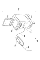
- FIG. 1 is a diagram showing an external configuration of a diagnostic imaging apparatus 100 according to an embodiment of the present invention.
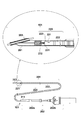
- FIG. 2 is a diagram showing an overall configuration of the probe portion and a cross-sectional configuration of the tip portion.
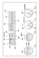
- FIG. 3A is a diagram illustrating an arrangement of ultrasonic transmission / reception units and optical transmission / reception units and an arrangement of cables in an imaging core.
- FIG. 3B is a diagram illustrating an arrangement of ultrasonic transmission / reception units and optical transmission / reception units and an arrangement of cables in an imaging core.
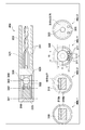
- FIG. 4 is a diagram illustrating the arrangement of the ultrasonic transmission / reception unit and the optical transmission / reception unit and the arrangement of the cables in the imaging core.
- FIG. 1 is a diagram showing an external configuration of an image diagnostic apparatus (an image diagnostic apparatus having an IVUS function and an OCT function) 100 according to an embodiment of the present invention.
- the diagnostic imaging apparatus 100 includes a probe unit 101, a scanner and pullback unit 102, and an operation control device 103.
- the scanner and pullback unit 102 and the operation control device 103 transmit various signals. Connected through a signal line 104.
- the probe unit 101 is directly inserted into a living body lumen such as a blood vessel, and transmits and receives an ultrasonic wave based on a pulse signal into the living body lumen and receives a reflected wave from a living tissue in the living body lumen. And an optical transmission / reception unit that continuously transmits the transmitted light (measurement light) into the living body lumen and continuously receives reflected light from living tissue in the living body lumen Is interpolated.
- the state in the living body lumen is measured by using the imaging core.
- the scanner and the pullback unit 102 are detachably attached to the probe unit 101, and operate in the axial direction and rotation direction in the living body lumen of the imaging core inserted in the probe unit 101 by driving a built-in motor. Specifies the operation. Further, the reflected wave received by the ultrasonic transmission / reception unit and the reflected light received by the optical transmission / reception unit are acquired and transmitted to the operation control apparatus 103.
- the operation control device 103 has a function for inputting various set values and a function for processing data obtained by the measurement and displaying it as a tomographic image in the living body lumen.
- 111 is a main body control unit, which generates ultrasonic data based on the reflected wave obtained by measurement, and processes the line data generated based on the ultrasonic data, An ultrasonic tomographic image is generated. Further, interference light data is generated by causing interference between the reflected light obtained by measurement and the reference light obtained by separating the light from the light source, and line data generated based on the interference light data. To generate an optical tomographic image.
- Reference numeral 111-1 is a printer and a DVD recorder, which prints the processing results in the main body control unit 111 or stores them as data.
- Reference numeral 112 denotes an operation panel, and the user inputs various setting values and instructions via the operation panel 112.
- Reference numeral 113 denotes an LCD monitor as a display device, which displays a tomographic image (ultrasonic tomographic image, optical tomographic image) generated by the main body control unit 111.
- the probe unit 101 is inserted into a living body lumen such as a blood vessel and a long catheter sheath 201 that is directly inserted into a living body lumen such as a blood vessel. And a connector unit 202 disposed on the user's hand side.
- a guide wire lumen tube 203 constituting a guide wire lumen is provided at the distal end of the catheter sheath 201.
- the catheter sheath 201 forms a continuous lumen from a connection portion with the guide wire lumen tube 203 to a connection portion with the connector portion 202.
- a transmission / reception unit 221 including an ultrasonic transmission / reception unit that transmits / receives an ultrasonic wave and an optical transmission / reception unit that transmits / receives light, an electric signal cable, and an optical fiber cable are provided.
- An imaging core 220 including a coil-shaped drive shaft 222 that transmits a rotational drive force for rotating the catheter sheath 201 is inserted over almost the entire length of the catheter sheath 201.
- the connector portion 202 includes a sheath connector 202a configured integrally with the proximal end of the catheter sheath 201, and a drive shaft connector 202b configured by rotatably fixing the drive shaft 222 to the proximal end of the drive shaft 222.
- a kink protector 211 is provided at the boundary between the sheath connector 202a and the catheter sheath 201. Thereby, predetermined rigidity is maintained, and bending (kink) due to a sudden change in physical properties can be prevented.
- the base end of the drive shaft connector 202b is detachably attached to the scanner and the pullback unit 102.
- the imaging core 220 including the transmission / reception unit 221 and the drive shaft 222 that transmits the rotational driving force for rotating the transmission / reception unit 221 at a high speed is inserted into the lumen of the catheter sheath 201 over almost the entire length.
- the probe unit 101 is formed.
- the transmission / reception unit 221 transmits ultrasonic waves and light toward the living tissue in the living body lumen, and receives reflected waves and reflected light from the living tissue in the living body lumen.
- the drive shaft 222 is formed in a coil shape, and an electric signal cable and an optical fiber cable (single-mode optical fiber cable) are arranged therein.
- the drive shaft 222 can move the transmission / reception unit 221 in the rotation direction and the axial direction with respect to the catheter sheath 201, is flexible, and has a characteristic capable of transmitting rotation well, for example, from a metal wire such as stainless steel. It is comprised by the multilayer multilayer coil which becomes.
- the housing 223 in which the transmission / reception unit 221 is arranged has a shape in which an opening is provided in a part of a short cylindrical metal pipe (on the upper side of the cylindrical surface). Powder injection molding) or the like.
- the housing 223 includes an ultrasonic transmission / reception unit and an optical transmission / reception unit as a transmission / reception unit 221 inside, and a proximal end side is connected to the drive shaft 222.
- a short coil-shaped elastic member 231 is provided on the tip side.
- the elastic member 231 is a stainless steel wire formed in a coil shape, and the elastic member 231 is disposed on the distal end side, thereby preventing the imaging core 220 from being caught in the catheter sheath 201 when moving the imaging core 220 back and forth.
- the reinforcing coil 232 is provided for the purpose of preventing a sudden bending of the distal end portion of the catheter sheath 201.
- the guide wire lumen tube 203 has a guide wire lumen into which a guide wire can be inserted.
- the guide wire lumen tube 203 is used to receive a guide wire inserted directly into a living body lumen such as a blood vessel, and to guide the catheter sheath 201 to an affected part by the guide wire.
- FIG. 3A is a diagram for explaining in detail the arrangement of the ultrasonic transmission / reception unit and the optical transmission / reception unit and the arrangement of the cables in the imaging core 220.
- FIG. 3A is a cross-sectional configuration when the imaging core 220 is viewed from the side, and 30b and 30c of FIG. 3A are ultrasonic emission positions or light output positions when the imaging core 220 is viewed from the front (front end side).
- the cross-sectional structure in each is shown.
- tip part of the imaging core 220 is provided with the ultrasonic transmission / reception part 310 and the optical transmission / reception part 320, and each transmission / reception part is a housing. It is arranged along the axial direction in 223.
- the ultrasonic transmission / reception unit 310 is disposed on the distal end side of the imaging core 220
- the optical transmission / reception unit 320 is disposed on the proximal end side of the imaging core 220.
- the cylindrical housing 223 is filled with an adhesive inside the cylindrical surface (in the example of 30b and 30c, inside the lower cylindrical surface), As a result, an adhesive upper surface is formed in the housing 223 along the axial direction.
- the ultrasonic transmission / reception unit 310 includes a vibrator 310a and a back material 310b, and the entire bottom surface of the back material 310b is positioned below the adhesive top surface (that is, embedded in the adhesive).
- the ultrasonic transmission / reception unit 310 is firmly fixed to the housing 223.
- the optical transmission / reception unit 320 is provided at the tip of the optical fiber cable 321, and includes a lower part of a ball lens part (optical element) 322 having a lens function for condensing light and a reflection function for reflection, and a lower part of the spacer straight part 323. However, it is located below the upper surface of the adhesive (that is, the lower part is embedded in the adhesive), and thereby the optical transmission / reception unit 320 is firmly fixed to the housing 223. .
- the reflective surface of the ball lens portion 322 is formed by coating a reflective material on the inclined surface.
- two electric signal cables for transmitting the reflected wave received in the ultrasonic transmission / reception part 310 to the operation control apparatus 103 311 is connected to the ultrasonic transmission / reception unit 310 at one end, and the drive shaft 222 (outside the housing 223) is routed in the housing 223 so as not to interfere with the light emission position of the optical transmission / reception unit 320. It is extended substantially in parallel.
- the electric signal cable 311 is wound around the optical fiber cable 321, one end of which is connected to the spacer straight portion 323 of the optical transmission / reception unit 320, while being wound so as to be twisted wiring.
- the electric signal cable 311 is wound around the optical fiber cable 321, one end of which is connected to the spacer straight portion 323 of the optical transmission / reception unit 320, while being wound so as to be twisted wiring.
- it is arranged in 222.
- FIG. 3B is a diagram for explaining in detail the arrangement of the ultrasonic transmission / reception unit 310 and the optical transmission / reception unit 320 and the arrangement of the cables in the housing 223.
- 3B shows a planar configuration when the imaging core 220 is viewed from above, and 31b-1, 31b-2, 31c-1, and 31c-2 in FIG. 3B are plural numbers shown in 31a in FIG. 3B.
- the cross-sectional configuration when viewed from the front end side of the housing 223 with the positions of the alternate long and short dash lines 341 to 344 as cutting positions is shown.
- the two electric signal cables 311 connected to the ultrasonic transmission / reception unit 310 are at the light emission position of the optical transmission / reception unit 320 (the position indicated by the alternate long and short dash line 343). It extends to the drive shaft 222 through the lower side of the upper surface of the adhesive (that is, once embedded in the adhesive at the light emission position).
- the electrical signal cable 311 connected to the ultrasonic transmission / reception unit 310 is between the connection terminal (refer to 31b-2) provided on the upper surface of the transducer 310a and the adhesive side surface (refer to 31c-2). If the imaging core 220 is rotated at a high speed, the electric signal cable 311 may generate vibrations if the imaging core 220 is rotated at a high speed.
- the electrical signal cable 311 is not passed above the upper surface of the adhesive, but below the upper surface of the adhesive at the light emission position.
- the electric signal cable 311 is prevented from being suspended in the housing 223, and is firmly fixed to the housing 223.
- the electric signal cable 311 does not generate vibration, and the influence on the measurement by the optical transceiver 320 can be avoided.
- the two electric signal cables 311 connected to the ultrasonic transmission / reception unit 310 have a space D below the ball lens unit 322 constituting the optical transmission / reception unit 320.
- the lens portion 322 is disposed so as to be smaller than the width W. 3B, when the imaging core 220 is viewed from the upper surface, a part of each of the two electric signal cables 311 overlaps the ball lens portion 322.
- the space is saved. Can be arranged.
- the probe unit 101 includes the ultrasonic transmission / reception unit 310 at the distal end side and the optical transmission / reception unit at the proximal end side in the housing 223 provided at the distal end portion of the imaging core 220.
- placing 320 Of the cylindrical surfaces forming the cylindrical housing 223, the inside of the lower cylindrical surface is filled with an adhesive, and then the entire bottom surface of the back material 310 b of the ultrasonic transmission / reception unit 310 is moved from the upper surface of the adhesive. Also, it is configured to be disposed on the lower side (that is, embedded in the adhesive). As a result, the ultrasonic transmission / reception unit 310 can be firmly fixed to the housing 223.
- the lower part of the ball lens part 322 and the lower part of the spacer straight part 323 of the optical transceiver 320 are embedded in the adhesive.
- the optical transceiver 320 can be firmly fixed to the housing 223.
- the electric signal cable 311 connected to the ultrasonic transmission / reception unit 310 is embedded in the adhesive at the light emission position of the optical transmission / reception unit 320.
- the electric signal cable 311 connected to the ultrasonic transmission / reception unit 310 is arranged below the ball lens unit 322 constituting the optical transmission / reception unit 320 at a distance D narrower than the width W of the ball lens unit 322. .
- the electric signal cable 311 can be arranged in a space-saving manner in the housing 223.
- the IVUS transceiver and the OCT transceiver can be firmly fixed to the housing 223, and can be arranged in a space-saving manner. explained. However, the effect that can be arranged in a space-saving manner becomes more prominent when the diameter of the ball lens portion 322 is increased.
- FIG. 4 is a diagram for explaining the arrangement of the ultrasonic transmission / reception unit 310 and the optical transmission / reception unit 320 and the cable arrangement in the housing 223 in detail. The difference from FIG. 3 is that the diameters of the ball lens portion 322 and the spacer straight portion 323 are large.
- the housing The diameter of the inner wall of 223 must be larger than the sum of the diameters of the ball lens portion 322 and the two electric signal cables 311.
- the electric signal cable 311 connected to the ultrasonic transmission / reception unit 310 is connected to the lower surface of the ball lens unit 322 at the light emission position of the optical transmission / reception unit 320. Accordingly, the electric signal cable 311 can be accommodated within the range of the width W of the ball lens portion 322.
- the downward protrusion amount ⁇ H of the electric signal cable 311 with respect to the height H of the ball lens portion 322 can be minimized (ball lens portion).
- the electrical signal cable 311 can be accommodated in the housing 223 in a smaller space.
- the diameter of the probe can be maintained even when the diameter of the ball lens portion 322 is increased.
- a ball lens is used as an optical element.
- the present invention is not limited to this, and a ball lens, a distributed refractive index type (GRIN) is used.
- GRIN distributed refractive index type
- You may comprise using optical elements, such as a lens, a reflection type prism, and an aspherical lens.
Landscapes
- Health & Medical Sciences (AREA)
- Life Sciences & Earth Sciences (AREA)
- Nuclear Medicine, Radiotherapy & Molecular Imaging (AREA)
- Biomedical Technology (AREA)
- Medical Informatics (AREA)
- Pathology (AREA)
- Veterinary Medicine (AREA)
- Engineering & Computer Science (AREA)
- Physics & Mathematics (AREA)
- Heart & Thoracic Surgery (AREA)
- Biophysics (AREA)
- Molecular Biology (AREA)
- Surgery (AREA)
- Animal Behavior & Ethology (AREA)
- General Health & Medical Sciences (AREA)
- Public Health (AREA)
- Radiology & Medical Imaging (AREA)
- Ultra Sonic Daignosis Equipment (AREA)
- Endoscopes (AREA)
Priority Applications (4)
| Application Number | Priority Date | Filing Date | Title |
|---|---|---|---|
| EP13768950.1A EP2832302B1 (de) | 2012-03-28 | 2013-03-19 | Sonde |
| JP2014507401A JP6030634B2 (ja) | 2012-03-28 | 2013-03-19 | プローブ |
| US14/491,289 US10213109B2 (en) | 2012-03-28 | 2014-09-19 | Probe |
| US16/282,460 US11298022B2 (en) | 2012-03-28 | 2019-02-22 | Probe |
Applications Claiming Priority (2)
| Application Number | Priority Date | Filing Date | Title |
|---|---|---|---|
| JP2012-072863 | 2012-03-28 | ||
| JP2012072863 | 2012-03-28 |
Related Child Applications (1)
| Application Number | Title | Priority Date | Filing Date |
|---|---|---|---|
| US14/491,289 Continuation US10213109B2 (en) | 2012-03-28 | 2014-09-19 | Probe |
Publications (1)
| Publication Number | Publication Date |
|---|---|
| WO2013145637A1 true WO2013145637A1 (ja) | 2013-10-03 |
Family
ID=49258951
Family Applications (1)
| Application Number | Title | Priority Date | Filing Date |
|---|---|---|---|
| PCT/JP2013/001865 Ceased WO2013145637A1 (ja) | 2012-03-28 | 2013-03-19 | プローブ |
Country Status (4)
| Country | Link |
|---|---|
| US (2) | US10213109B2 (de) |
| EP (1) | EP2832302B1 (de) |
| JP (1) | JP6030634B2 (de) |
| WO (1) | WO2013145637A1 (de) |
Cited By (2)
| Publication number | Priority date | Publication date | Assignee | Title |
|---|---|---|---|---|
| WO2019004355A1 (ja) * | 2017-06-29 | 2019-01-03 | テルモ株式会社 | 画像診断用カテーテル |
| JP2022009133A (ja) * | 2018-03-30 | 2022-01-14 | テルモ株式会社 | 画像診断用カテーテル |
Families Citing this family (12)
| Publication number | Priority date | Publication date | Assignee | Title |
|---|---|---|---|---|
| WO2013145637A1 (ja) * | 2012-03-28 | 2013-10-03 | テルモ株式会社 | プローブ |
| JP6869951B2 (ja) | 2015-04-16 | 2021-05-12 | ジェンテュイティ・リミテッド・ライアビリティ・カンパニーGentuity, LLC | 撮像システム |
| WO2017040484A1 (en) | 2015-08-31 | 2017-03-09 | Gentuity, Llc | Imaging system includes imaging probe and delivery devices |
| JP6599702B2 (ja) * | 2015-09-10 | 2019-10-30 | テルモ株式会社 | 画像診断用カテーテル |
| EP3700406A4 (de) | 2017-11-28 | 2021-12-29 | Gentuity LLC | Bildgebungssystem |
| JP6962850B2 (ja) * | 2018-03-30 | 2021-11-05 | テルモ株式会社 | 画像診断用カテーテル |
| EP3801282A1 (de) * | 2018-06-06 | 2021-04-14 | The General Hospital Corporation | Miniaturisierter intravaskulärer fluoreszenzultraschall-abbildungskatheter |
| JP7183616B2 (ja) * | 2018-08-02 | 2022-12-06 | ソニーグループ株式会社 | 撮像装置、信号処理装置、信号処理方法およびプログラム |
| US12144649B2 (en) * | 2018-08-14 | 2024-11-19 | Biosense Webster (Israel) Ltd. | Guidewire with an integrated optical fiber |
| US12262872B2 (en) | 2018-09-17 | 2025-04-01 | Gentuity, Llc | Imaging system with optical pathway |
| US12364385B2 (en) | 2019-04-30 | 2025-07-22 | Gentuity, Llc | Imaging probe with fluid pressurization element |
| JP2022533212A (ja) | 2019-05-21 | 2022-07-21 | ジェンテュイティ・リミテッド・ライアビリティ・カンパニー | 患者のoctガイド処置システム及び方法 |
Citations (6)
| Publication number | Priority date | Publication date | Assignee | Title |
|---|---|---|---|---|
| JPH1156752A (ja) | 1997-08-28 | 1999-03-02 | Olympus Optical Co Ltd | 被検体内断層イメージング装置 |
| JP2005095624A (ja) * | 2003-09-22 | 2005-04-14 | Siemens Ag | 医療検査および/または治療システム |
| JP2006280449A (ja) * | 2005-03-31 | 2006-10-19 | Fujinon Corp | 画像診断装置 |
| JP2009183416A (ja) * | 2008-02-05 | 2009-08-20 | Yamaguchi Univ | 診断用カテーテル |
| JP2010508973A (ja) | 2006-11-08 | 2010-03-25 | ライトラブ イメージング, インコーポレイテッド | 光−音響イメージングデバイスおよび方法 |
| JP2011519689A (ja) * | 2008-05-07 | 2011-07-14 | インフラレデックス, インコーポレイテッド | 脈管内分析のためのマルチモーダルカテーテルシステム |
Family Cites Families (6)
| Publication number | Priority date | Publication date | Assignee | Title |
|---|---|---|---|---|
| US5876344A (en) * | 1997-12-09 | 1999-03-02 | Endosonics Corporation | Modular imaging/treatment catheter assembly and method |
| CN1322839C (zh) * | 2004-06-28 | 2007-06-27 | 天津大学 | 医用经内窥镜微型超声-oct探头 |
| US7599588B2 (en) * | 2005-11-22 | 2009-10-06 | Vascular Imaging Corporation | Optical imaging probe connector |
| DE102006002898A1 (de) * | 2006-01-20 | 2007-07-26 | Siemens Ag | Vorrrichtung zur Durchführung einer Cutting-Balloon-Intervention |
| US10219780B2 (en) * | 2007-07-12 | 2019-03-05 | Volcano Corporation | OCT-IVUS catheter for concurrent luminal imaging |
| WO2013145637A1 (ja) * | 2012-03-28 | 2013-10-03 | テルモ株式会社 | プローブ |
-
2013
- 2013-03-19 WO PCT/JP2013/001865 patent/WO2013145637A1/ja not_active Ceased
- 2013-03-19 JP JP2014507401A patent/JP6030634B2/ja active Active
- 2013-03-19 EP EP13768950.1A patent/EP2832302B1/de active Active
-
2014
- 2014-09-19 US US14/491,289 patent/US10213109B2/en active Active
-
2019
- 2019-02-22 US US16/282,460 patent/US11298022B2/en active Active
Patent Citations (6)
| Publication number | Priority date | Publication date | Assignee | Title |
|---|---|---|---|---|
| JPH1156752A (ja) | 1997-08-28 | 1999-03-02 | Olympus Optical Co Ltd | 被検体内断層イメージング装置 |
| JP2005095624A (ja) * | 2003-09-22 | 2005-04-14 | Siemens Ag | 医療検査および/または治療システム |
| JP2006280449A (ja) * | 2005-03-31 | 2006-10-19 | Fujinon Corp | 画像診断装置 |
| JP2010508973A (ja) | 2006-11-08 | 2010-03-25 | ライトラブ イメージング, インコーポレイテッド | 光−音響イメージングデバイスおよび方法 |
| JP2009183416A (ja) * | 2008-02-05 | 2009-08-20 | Yamaguchi Univ | 診断用カテーテル |
| JP2011519689A (ja) * | 2008-05-07 | 2011-07-14 | インフラレデックス, インコーポレイテッド | 脈管内分析のためのマルチモーダルカテーテルシステム |
Non-Patent Citations (1)
| Title |
|---|
| See also references of EP2832302A4 |
Cited By (6)
| Publication number | Priority date | Publication date | Assignee | Title |
|---|---|---|---|---|
| WO2019004355A1 (ja) * | 2017-06-29 | 2019-01-03 | テルモ株式会社 | 画像診断用カテーテル |
| JPWO2019004355A1 (ja) * | 2017-06-29 | 2020-04-30 | テルモ株式会社 | 画像診断用カテーテル |
| JP7173968B2 (ja) | 2017-06-29 | 2022-11-16 | テルモ株式会社 | 画像診断用カテーテル |
| US11596310B2 (en) | 2017-06-29 | 2023-03-07 | Terumo Kabushiki Kaisha | Image diagnosis catheter |
| JP2022009133A (ja) * | 2018-03-30 | 2022-01-14 | テルモ株式会社 | 画像診断用カテーテル |
| JP7179943B2 (ja) | 2018-03-30 | 2022-11-29 | テルモ株式会社 | 画像診断用カテーテル |
Also Published As
| Publication number | Publication date |
|---|---|
| JP6030634B2 (ja) | 2016-11-24 |
| EP2832302A4 (de) | 2015-12-02 |
| US20150005628A1 (en) | 2015-01-01 |
| EP2832302B1 (de) | 2022-08-24 |
| JPWO2013145637A1 (ja) | 2015-12-10 |
| US11298022B2 (en) | 2022-04-12 |
| EP2832302A1 (de) | 2015-02-04 |
| US10213109B2 (en) | 2019-02-26 |
| US20190183341A1 (en) | 2019-06-20 |
Similar Documents
| Publication | Publication Date | Title |
|---|---|---|
| JP6030634B2 (ja) | プローブ | |
| JP6584467B2 (ja) | 光−音響イメージングデバイス | |
| JP6117772B2 (ja) | プローブ及び画像診断装置 | |
| EP2832303B1 (de) | Sonde und diagnostische bildgebungsvorrichtung | |
| JP5188242B2 (ja) | 生体内挿入用プローブ | |
| JP5563582B2 (ja) | 画像診断装置 | |
| JP5628895B2 (ja) | プローブ及び光画像診断装置 | |
| JPWO2014162367A1 (ja) | 画像診断装置及びプログラム | |
| WO2015141136A1 (ja) | 変換コネクタ、及び、カテーテルセット | |
| JP6829124B2 (ja) | 画像診断装置 | |
| JP2023144742A (ja) | 画像診断用カテーテル | |
| JP6559985B2 (ja) | 画像診断プローブ | |
| WO2024176636A1 (ja) | 画像診断用カテーテルの製造方法、及び、画像診断用カテーテル | |
| JP2021065725A (ja) | 画像診断装置 |
Legal Events
| Date | Code | Title | Description |
|---|---|---|---|
| 121 | Ep: the epo has been informed by wipo that ep was designated in this application |
Ref document number: 13768950 Country of ref document: EP Kind code of ref document: A1 |
|
| WWE | Wipo information: entry into national phase |
Ref document number: 2013768950 Country of ref document: EP |
|
| ENP | Entry into the national phase |
Ref document number: 2014507401 Country of ref document: JP Kind code of ref document: A |
|
| NENP | Non-entry into the national phase |
Ref country code: DE |