WO2013145663A1 - 角度ダイバーシチ受信装置及び角度ダイバーシチ受信方法 - Google Patents
角度ダイバーシチ受信装置及び角度ダイバーシチ受信方法 Download PDFInfo
- Publication number
- WO2013145663A1 WO2013145663A1 PCT/JP2013/001941 JP2013001941W WO2013145663A1 WO 2013145663 A1 WO2013145663 A1 WO 2013145663A1 JP 2013001941 W JP2013001941 W JP 2013001941W WO 2013145663 A1 WO2013145663 A1 WO 2013145663A1
- Authority
- WO
- WIPO (PCT)
- Prior art keywords
- phased array
- diversity
- angle
- combining
- angle diversity
- Prior art date
- Legal status (The legal status is an assumption and is not a legal conclusion. Google has not performed a legal analysis and makes no representation as to the accuracy of the status listed.)
- Ceased
Links
Images




Classifications
-
- H—ELECTRICITY
- H04—ELECTRIC COMMUNICATION TECHNIQUE
- H04B—TRANSMISSION
- H04B7/00—Radio transmission systems, i.e. using radiation field
- H04B7/02—Diversity systems; Multi-antenna system, i.e. transmission or reception using multiple antennas
- H04B7/04—Diversity systems; Multi-antenna system, i.e. transmission or reception using multiple antennas using two or more spaced independent antennas
- H04B7/08—Diversity systems; Multi-antenna system, i.e. transmission or reception using multiple antennas using two or more spaced independent antennas at the receiving station
- H04B7/0837—Diversity systems; Multi-antenna system, i.e. transmission or reception using multiple antennas using two or more spaced independent antennas at the receiving station using pre-detection combining
- H04B7/0842—Weighted combining
- H04B7/0865—Independent weighting, i.e. weights based on own antenna reception parameters
-
- H—ELECTRICITY
- H04—ELECTRIC COMMUNICATION TECHNIQUE
- H04B—TRANSMISSION
- H04B1/00—Details of transmission systems, not covered by a single one of groups H04B3/00 - H04B13/00; Details of transmission systems not characterised by the medium used for transmission
- H04B1/06—Receivers
- H04B1/10—Means associated with receiver for limiting or suppressing noise or interference
- H04B1/1081—Reduction of multipath noise
-
- H—ELECTRICITY
- H01—ELECTRIC ELEMENTS
- H01Q—ANTENNAS, i.e. RADIO AERIALS
- H01Q25/00—Antennas or antenna systems providing at least two radiating patterns
-
- H—ELECTRICITY
- H01—ELECTRIC ELEMENTS
- H01Q—ANTENNAS, i.e. RADIO AERIALS
- H01Q3/00—Arrangements for changing or varying the orientation or the shape of the directional pattern of the waves radiated from an antenna or antenna system
- H01Q3/26—Arrangements for changing or varying the orientation or the shape of the directional pattern of the waves radiated from an antenna or antenna system varying the relative phase or relative amplitude of energisation between two or more active radiating elements; varying the distribution of energy across a radiating aperture
- H01Q3/2605—Array of radiating elements provided with a feedback control over the element weights, e.g. adaptive arrays
-
- H—ELECTRICITY
- H04—ELECTRIC COMMUNICATION TECHNIQUE
- H04B—TRANSMISSION
- H04B7/00—Radio transmission systems, i.e. using radiation field
- H04B7/02—Diversity systems; Multi-antenna system, i.e. transmission or reception using multiple antennas
- H04B7/04—Diversity systems; Multi-antenna system, i.e. transmission or reception using multiple antennas using two or more spaced independent antennas
- H04B7/08—Diversity systems; Multi-antenna system, i.e. transmission or reception using multiple antennas using two or more spaced independent antennas at the receiving station
- H04B7/0882—Diversity systems; Multi-antenna system, i.e. transmission or reception using multiple antennas using two or more spaced independent antennas at the receiving station using post-detection diversity
- H04B7/0885—Diversity systems; Multi-antenna system, i.e. transmission or reception using multiple antennas using two or more spaced independent antennas at the receiving station using post-detection diversity with combination
Definitions
- the present invention relates to an angle diversity receiving apparatus and an angle diversity receiving method.
- FIG. 7 is a block diagram showing a configuration of an angle diversity receiving device 600 related to the present invention.
- the angle diversity receiver 600 includes an antenna group 611 including two horn antennas 61A and 61B.
- This angle diversity receiver 600 converts a received signal from the horn antenna 61A into a band-pass filter (BPF) 221, a low noise amplifier (low noise amplifier, LNA) 231, a reception frequency converter (down converter).
- BPF band-pass filter
- LNA low noise amplifier
- D / C 241, automatic gain controller (AGC) 251
- AMF adaptive matched filter
- the angle diversity receiving device 600 receives the received signal from the horn antenna 61B via the band-pass filter 222, the low noise amplifier 232, the reception frequency converter 242, the automatic gain controller 252 and the adaptive matched filter 132. . In this way, the angle diversity receiving device 600 receives the reception signals from the horn antennas 61A and 61B as two branches (reception systems) where angle diversity is performed.
- Band-pass filters (BPF) 221 and 222 pass only signals in a frequency band necessary for reception.
- Low noise amplifiers (LNA) 231 and 232 amplify the received signal.
- Reception frequency converters (down converters, D / C) 241 and 242 perform frequency conversion of reception signals.
- Automatic gain controllers (AGC) 251 and 252 amplify the reception signal so as to suppress the amplitude change of the reception signal output to the subsequent stage.
- the adaptive matched filters 131 and 132 reduce unnecessary signals included in the received signals of each branch.
- the diversity combining circuit 140 diversity combines the signals input from the adaptive matched filters 131 and 132.
- An automatic equalization circuit (decision feedback equalizer, decision feedback equalizer, DFE) 150 performs automatic equalization on the diversity combined signal and reproduces the received signal.
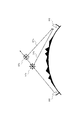
- FIG. 8 is a diagram for explaining tropospheric scattering propagation.
- the reception antenna 812 corresponds to, for example, the antenna group 611 of the angle diversity reception device 600 illustrated in FIG.
- the radio wave radiated from the transmitting station 811 is scattered at the first scattering point STa and the second scattering point STb, and is received by the antenna group 812 as signals in the directivity directions DTa and DTb, respectively.
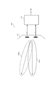
- FIG. 9 is a diagram for explaining the operation of the angle diversity receiver 600 according to the related art.
- the angle diversity receiver 600 shown in FIGS. 7 and 9 operates as follows. As shown in FIG. 9, the two directivity directions DR6a and DR6b are each fixed at a predetermined angle. Then, the antenna group 611 performs angle diversity processing on the received signals coming from the directivity directions DR6a and DR6b.
- the angle diversity receiving device 600 receives an incoming radio wave in the transport direction DTa in FIG. 8 by the directivity direction DR6a in FIG. 9, and receives an incoming radio wave in the transport direction DTb in FIG. 8 by the directivity direction DR6b.
- the transport direction DTa or DTb changes.
- the strength of the received signal in the angle diversity receiving apparatus 600 may be significantly reduced.
- the reception level may decrease as a result of the radio wave arrival azimuth changing as the propagation condition changes.
- the situation of scatter propagation in the troposphere changes greatly due to weather changes and the like.
- the azimuth of the antenna is fixed, there is a problem that long-period fading of 10 to 20 and several dB occurs in propagation loss throughout the year, and the reception level of radio waves may be lowered.
- the angles between the plurality of receiving horns are set in advance so that the correlation value between the branches does not increase.
- the angle diversity receiver has a problem that the correlation value between branches increases with a change in the tropospheric scattering state, and the diversity effect may decrease.
- the angle diversity receiver can avoid a decrease in reception level even if the angle of arrival of radio waves changes, and maintains the diversity effect even if the tropospheric scatter propagation situation changes It is requested to do.
- An object of the present invention is to provide an angle diversity receiving apparatus and an angle diversity receiving method capable of avoiding a decrease in reception level even when a radio wave arrival angle changes, and maintaining a diversity effect even when there is a change in tropospheric scatter propagation. Is to provide.
- An angle diversity receiving apparatus is an angle diversity receiving apparatus that performs angle diversity reception by forming an angle diversity branch from a reception signal of an array antenna, and receives reception signals of a plurality of antenna elements included in the array antenna.
- a plurality of phased array combining means for generating a reception signal of the branch by performing phased array combining; and a correlation control means for outputting a correlation value between the reception signals of the two branches, the phased array combining means Is characterized in that the angle difference in the directivity direction between the branches for which the correlation value is calculated is controlled so that the correlation value becomes small.
- An angle diversity reception method is an angle diversity reception method for performing angle diversity reception by forming a diversity branch by a reception signal of an array antenna, wherein the reception signals of a plurality of antenna elements included in the array antenna are phased.
- a reception signal of the branch is generated, a correlation value between the reception signals of the two branches is output, and an angle difference in a directivity direction between the branches where the correlation value is calculated is calculated as the correlation Control is made so that the value becomes smaller.
- the angle diversity receiving apparatus and angle diversity receiving method of the present invention can avoid a decrease in reception level even if the angle of arrival of radio waves changes, and maintain the diversity effect even if the tropospheric scatter propagation situation changes. Can do.
- FIG. 6 is a block diagram illustrating an example of a specific configuration of the angle diversity receiving device illustrated in FIG. 5. It is a block diagram which shows the structure of the angle diversity receiver relevant to this invention. It is a figure for demonstrating tropospheric scattering propagation. It is a figure for demonstrating operation
- FIG. 1 is a schematic block diagram showing a configuration of an angle diversity receiving apparatus 100 according to the first embodiment of the present invention.
- the angle diversity receiver 100 of the first embodiment includes an array antenna 10, M number of phased array combining circuits 121-12M, M number of adaptive matched filters 131-13M, and a diversity combining circuit 140.
- the automatic equalization circuit 150 and the correlation control circuit 160 are included.
- the array antenna 10 includes N antenna elements 111, 112,.
- M and N are integers of 2 or more, and M is N or less.
- the received signal from the antenna element 111-11N is input to the phased array combining circuit 121-12M.
- Each of the phased array combining circuits 121-12M selects two or more received signals from the received signals received from the antenna elements 111-11N and performs phased array combining.
- the phased array synthesis circuit 121-12M constitutes M branches.
- the outputs of the phased array combining circuit 121-12M are input to M adaptive matched filters 131-13M, respectively, and combined by the diversity combining circuit 140. In this manner, angle diversity is combined for M branches.
- the output of the diversity combining circuit 140 is automatically equalized by the automatic equalization circuit 150, and a received data signal is obtained.
- the angle diversity receiving apparatus 100 controls the directivity direction of the branch following the change of the arrival direction of the radio wave by the phased array combining circuit 121-12M to which a plurality of antenna elements are connected. In addition, the angle diversity receiving apparatus 100 forms a plurality of subarrays from a plurality of branches, and uses the outputs of the subarrays as reception signals of the branches of the angle diversity. The angle diversity receiving apparatus 100 performs adaptive matching filtering between the branches of the angle diversity, performs maximum ratio combining including time-distributed multipaths, and performs optimal angle diversity reception.
- the correlation control circuit 160 calculates a correlation value between two outputs selected from the outputs of the phased array synthesis circuit 121-12M.
- the calculated correlation value is input to the phased array synthesis circuit that outputs the two selected signals.
- the correlation control circuit 160 may sequentially calculate correlation values of two outputs among the M outputs of the phased array synthesis circuit 121-12M.
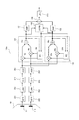
- FIG. 2 is a block diagram showing an example of a specific configuration of the angle diversity receiving apparatus 100 shown in FIG.
- the angle diversity receiver 100a includes an array antenna 10, phased array combining circuits 121 and 122, adaptive matched filters (AMF) 131 and 132, a diversity combining circuit 140, a correlation control circuit (CORR) 160, and automatic equalization. Circuit (decision feedback equalizer, DFE) 150.
- the array antenna 10 includes antenna elements 11a and 11b.
- the angle diversity receiving apparatus 100a further includes band pass filters (BPF) 221 and 222 and low noise amplifiers (LNA) 231 and 232 between the array antenna 10 and the phased array combining circuits 121 and 122. And reception frequency converters (down converters, D / C) 241 and 242 and automatic gain controllers (AGC) 251 and 252.
- BPF band pass filters
- LNA low noise amplifiers
- AGC automatic gain controllers
- bandpass filters 221 and 222 The functions of the bandpass filters 221 and 222, the low noise amplifiers 231 and 232, the reception frequency converters 241 and 242, and the automatic gain controllers 251 and 252 are the same as the blocks having the same name shown in FIG. .
- the array antenna 10 includes antenna elements 111 and 112.
- Each of the antenna elements 111 and 112 may be a horn antenna type provided with an antenna reflector.
- the angle diversity receiving apparatus 100a linearly combines the received signals received by the antenna elements 111 and 112 by the phased array combining circuit 121 or 122, respectively. As such, the angle diversity receiving apparatus 100a controls the phased array.
- the correlation control circuit 160 calculates the correlation between the output signal of the phased array synthesis circuit 121 and the output signal of the phased array synthesis circuit 122 and outputs the correlation to the phased array synthesis circuits 121 and 122.
- the complex coefficient multiplied by each subarray in the phased array synthesis circuit 121 is W1
- the complex coefficient multiplied by each subarray in the phased array synthesis circuit 122 is W2.
- W1 is multiplied by the signal of each subarray by the complex multiplier 19a or 19b.
- the outputs of the complex multipliers 19a and 19b are added by the adder 19c and output from the phased array synthesis circuit 121.
- W2 is multiplied by the signal of each subarray by the complex multiplier 20a or 20b.
- the outputs of the complex multipliers 20 a and 20 b are added by the adder 20 c and output from the phased array combining circuit 122.
- the complex coefficient W1 is corrected based on the output of the phased array combining circuit 121 and the correlation value input from the correlation control circuit 160 so that the output of the phased array combining circuit 121 is maximized.
- the complex coefficient W2 is corrected based on the output of the phased array combining circuit 122 and the correlation value input from the correlation control circuit 160 so that the output of the phased array combining circuit 122 is maximized.
- weighting factors W1 and W2 are calculated by the following adaptive algorithm.
- W1 (n + 1) W1 (n) + (1- ⁇ ) ⁇ r1 * (n) ⁇ y1 (n) ⁇ (Formula 1)
- W2 (n + 1) W2 (n) + (1- ⁇ ) ⁇ r2 * (n) ⁇ y2 (n) ⁇ (Expression 2)
- r1 and r2 are input signal vectors (two-dimensional vectors in FIG. 2) of the phased array synthesis circuits 121 and 122, respectively.
- Y1 and y2 indicate output signal vectors of the phased array combining circuits 121 and 122, respectively.
- the symbol * indicates a complex conjugate
- n in parentheses is the nth sample
- ⁇ is a correction coefficient.
- the reason for multiplying by (1 ⁇ ) is that the algorithm is a positive feedback type, so that the calculation result is prevented from being diverged and multiplied by a multiplier for adaptive convergence. It is.
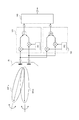
- phased array combining circuits 121 and 122 independently control the direction of diversity branch so that the reception level is maximized.
- An explanatory diagram of the operation is shown in FIG. DR1a is the directivity direction of the first diversity branch by the phased array combining circuit 121.
- DR1b is the direction of the second diversity branch directed by the phased array combining circuit 122.
- the angle in the directivity direction is variable.
- angle diversity receiving devices 100 and 100a of the first embodiment are applied to tropospheric scatter propagation.
- the array antenna of the receiving station corresponds to the receiving antenna 812.
- the transmission beam transmitted from the transmission station 811 is scattered in the troposphere.
- the scattering region is called a scattering volume and has a spatial spread. Therefore, the signal of the directivity direction DTa from the first scattering point STa and the signal of the directivity direction DTb from the second scattering point STb are respectively received by the receiving antennas of the non-line-of-sight receiving stations (angle diversity receiving devices 100 and 100a). Arrives at 812.
- the scattering points STa and STb are spatially separated, and each scattering phenomenon varies randomly. For this reason, the scattering phenomenon at the scattering points STa and STb is uncorrelated with each other. Therefore, the received signals between the directivity directions DTa and DTb are also uncorrelated fading signals.
- Patent Document 2 shows that if the correlation value between branches of angle diversity is 0.6 or less, it is effective as angle diversity.
- the correlation value decreases and the angle formed by the directivity directions DTa and DTb increases. Therefore, in the present invention, by controlling the directivity direction by the phased array, the directivity directions DR1a and DR1b that increase the angle between the branches of the angle diversity are formed, the mutual correlation value is reduced, and the diversity effect is maintained. .
- FIG. 4 is a diagram showing the relationship between the correlation value between the branches of angle diversity and the spacing in the directing direction (angle difference between beams).
- the vertical axis represents the inter-branch correlation value ⁇ of the angle diversity
- the horizontal axis represents the angular difference ⁇ between the beams of the branches.
- the inter-branch correlation value ⁇ of the angle diversity decreases as the angular difference ⁇ between the beams of the branch increases.
- the directivity direction vectors (directivity) G1 and G2 of DR1a and DR1b shown in FIG. 3 are defined as follows.
- G1 g1 ⁇ exp (j ⁇ 1) (Formula 3)
- G2 g2 ⁇ exp (j ⁇ 2) (Formula 4)
- g1 represents the amplitude of the directivity vector in the directivity direction DR1a
- ⁇ 1 represents the elevation angle of the directivity vector
- g2 represents the amplitude of the directivity vector in the directivity direction DR1b
- ⁇ 2 represents the elevation angle of the directivity vector.
- the above vectors G1 and G2 are directivity vectors indicated by the respective branches when the outputs of the phased array combining circuits 121 and 122 are maximized. For this reason, when the scattering points STa and STb shown in FIG. 8 are close to each other, the directivities G1 and G2 may approach each other depending on the situation. In this case, the correlation value between the branches increases, and the diversity effect decreases.
- a correlation value between branches is obtained, and exp (+ j ⁇ ) is added to the vector G1 so that the correlation value decreases, that is, the angle difference ⁇ increases, based on the relationship shown in FIG. / 2).
- the vector G2 is multiplied by exp ( ⁇ j ⁇ / 2). That is, the vectors G1 and G2 perform perturbation correction on ⁇ as follows.
- the angle diversity receiver of the first embodiment can avoid a decrease in reception level even if the angle at which the radio wave arrives changes, and maintains the diversity effect even if the tropospheric scatter propagation situation changes. be able to.
- angle diversity receiver 100 shown in FIG. 1 can also be configured as follows.
- the angle diversity receiving apparatus 100 is an angle diversity receiving apparatus that forms an angle diversity branch by receiving signals from an array antenna and performs angle diversity reception.
- Angle diversity receiving apparatus 100 includes an array antenna, phased array combining circuits 20-1 to 20-N, and correlation control circuit 160.
- the phased array combining circuit 201-20N generates a branch reception signal by performing phased array combining of reception signals of a plurality of antenna elements included in the array antenna. Then, the correlation control means outputs a correlation value between the reception signals of the branches. Further, the phased array synthesis circuit 201-20N controls the angle difference in the directivity direction between the branches so that the correlation value output from the correlation control means 160 becomes small.
- the angle diversity receiving apparatus 100 can avoid a decrease in reception level even if the angle at which the radio wave arrives changes by performing phased array synthesis. And the angle diversity receiver 100 maintains the diversity effect even if there is a change in the situation of tropospheric scatter propagation by controlling the angle difference in the directivity direction between the branches so that the correlation value between the branches becomes small. Can do.
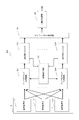
- FIG. 5 is a schematic block diagram showing a configuration of an angle diversity receiver 200 according to the second embodiment of the present invention.
- the angle diversity receiving apparatus 200 is different from the first embodiment in that a cross-correlation between outputs of a plurality of phased array combining circuits is obtained from a complex tap multiplication coefficient of an adaptive matched filter.
- the correlation control circuit 160 receives the complex tap multiplication coefficient of the adaptive matched filter 131-13M, and the correlation control circuit 160 selects the selected 2 of the adaptive matched filters 131-13M.
- the correlation value is calculated based on the complex tap multiplication coefficients of the two adaptive matched filters. Note that the configuration and basic operation of the angle diversity receiving apparatus 200 other than the input to the correlation control circuit 160 are the same as those of the angle diversity receiving apparatus 100 described in FIG. .
- FIG. 6 is a block diagram showing an example of a specific configuration of the angle diversity receiving apparatus 200 shown in FIG.
- the angle diversity receiver 200a is similar to the angle diversity receiver 100a of FIG. 2 in that the array antenna 10, phased array combining circuits 121 and 122, adaptive matched filters (AMF) 131 and 132, A diversity combining circuit 140, a correlation control circuit (CORR) 160, and an automatic equalization circuit (determination feedback equalizer, DFE) 150 are provided.
- the array antenna 10 includes antenna elements 11a and 11b.
- the angle diversity receiving apparatus 200a further includes band pass filters (BPF) 221 and 222 and low noise amplifiers (LNA) 231 and 232 between the array antenna 10 and the phased array combining circuits 121 and 122. And reception frequency converters (down converters, D / C) 241 and 242 and automatic gain controllers (AGC) 251 and 252.
- BPF band pass filters
- LNA low noise amplifiers
- AGC automatic gain controllers
- bandpass filters 221 and 222 The functions of the bandpass filters 221 and 222, the low noise amplifiers 231 and 232, the reception frequency converters 241 and 242, and the automatic gain controllers 251 and 252 are the same as the blocks having the same name shown in FIG. .
- Each of the antenna elements 111 and 112 may be a horn antenna type provided with an antenna reflector.
- the angle diversity receiving apparatus 200a linearly synthesizes the reception signals of the antenna elements 111 and 112 by the phased array synthesis circuits 121 and 122. Thereby, the phased array is controlled.
- the cross-correlation between the output of the phased array combining circuit 121 and the output of the phased array combining circuit 122 is obtained from the complex tap multiplication coefficients of the adaptive matched filters 131 and 132.
- the correlation control circuit 160 calculates a correlation value between the complex tap multiplication coefficient of the adaptive matched filter 131 and the complex tap multiplication coefficient of the adaptive matched filter 132, and outputs the correlation value to the phased array synthesis circuits 121 and 122.
- the complex coefficient multiplied by each subarray in the phased array synthesis circuit 121 is W1
- the complex coefficient multiplied by each subarray in the second phased array synthesis circuit 122 is W2.
- the complex coefficient W1 is adaptively corrected so that the output of the phased array synthesis circuit 121 is maximized based on the output of the phased array synthesis circuit 121 and the correlation value input from the correlation control circuit 160.
- the complex coefficient W2 is adaptively corrected so that the output of the phased array synthesis circuit 122 is maximized based on the output of the phased array synthesis circuit 122 and the correlation value input from the correlation control circuit 160.
- W1 and W2 are calculated by Expression (1) and Expression (2), as in the first embodiment. Further, the directivity direction vectors (directivity) G1 and G2 of the branch of the angle diversity are obtained by the equations (3) to (6).
- the outputs of the phased array combining circuits 121 and 122 are maximized using the equations (1) to (6) described in the first embodiment, and the directional vectors G1 and G2 are obtained.
- the angle diversity effect can be maintained while maintaining a low correlation between the angle diversity.
- the angle diversity receiver of the second embodiment can avoid a decrease in reception level even when the angle of arrival of radio waves changes, as well as the tropospheric scattering, similarly to the angle diversity receiver of the second embodiment.
- the diversity effect can be maintained even when the propagation situation changes.
- the angle diversity receiving apparatus includes, as branches, a plurality of phased array combining circuits for performing phased array combining by multiplying and adding reception signals of a plurality of antenna elements by complex coefficients, and a plurality of phased array combining circuits. Based on the outputs of each of the array synthesis circuits, the correlation control circuit for controlling the angle difference between the directivity directions of the branches so that the correlation value between the branches is minimized, and the outputs of the plurality of phased array synthesis circuits are respectively input.
- An angle diversity receiving apparatus includes, as branches, a plurality of phased array combining circuits for performing phased array combining by multiplying and adding reception coefficients of a plurality of antenna elements by complex coefficients, and a plurality of phased array combining circuits.
- a plurality of adaptive matched filters to which the outputs of the array combining circuit are respectively input, a diversity combining circuit that performs angle diversity combining by combining the outputs of the plurality of adaptive matching filters, and an automatic that automatically equalizes the output of the diversity combining circuit Based on complex tap multiplication coefficients of a plurality of adaptive matched filters, an equalization circuit and a correlation control circuit that controls the angle difference in the directivity direction between the branches so that the correlation value between the branches is minimized.
- the plurality of antenna elements of the third and fourth embodiments of the present invention may be horn antenna types.
- the angle diversity receivers of the first to fourth embodiments can be used for communication using angle diversity in propagation in which multipath fading occurs. Further, as an application example of the present invention, it can be used for tropospheric scatter propagation communication or land mobile communication.
Landscapes
- Engineering & Computer Science (AREA)
- Computer Networks & Wireless Communication (AREA)
- Signal Processing (AREA)
- Radio Transmission System (AREA)
- Variable-Direction Aerials And Aerial Arrays (AREA)
Description
図1は、本発明の第1の実施形態による角度ダイバーシチ受信装置100の構成を示す概略的なブロック図である。図1において、第1の実施形態の角度ダイバーシチ受信装置100は、アレイアンテナ10と、M個のフェーズドアレイ合成回路121-12Mと、M個の適応整合フィルタ131~13Mと、ダイバーシチ合成回路140と、自動等化回路150と、相関制御回路160とを有している。アレイアンテナ10は、N個のアンテナ素子111、112、・・・、11Nを備える。ここで、M及びNは2以上の整数であり、MはN以下である。
W2(n+1)=W2(n)+(1-μ){r2*(n)・y2(n)} ・・・(式2)
ここで、r1及びr2は、フェーズドアレイ合成回路121及び122それぞれの入力信号ベクトル(図2では2次元ベクトル)である。また、y1及びy2は、フェーズドアレイ合成回路121及び122それぞれの出力信号ベクトルを示す。記号*は複素共役を示し、括弧内のnはn番目のサンプル、μは修正係数を示す。式1及び式2において、(1-μ)を乗算している理由は、上記アルゴリズムが正帰還型であることから、計算結果の発散を防止し、適応収束させるための乗数を逐次乗算するためである。
G2=g2・exp(jθ2) ・・・(式4)
上記の式3、4において、g1は指向方向DR1aの指向ベクトルの振幅、θ1は当該指向ベクトルの仰角、g2は指向方向DR1bの指向ベクトルの振幅、θ2は当該指向ベクトルの仰角を示す。
G2=g2・exp(jθ2)・exp(-jΔθ/2) ・・・(式6)
以上の指向方向ベクトルG1とG2を摂動補正することにより、角度ダイバーシチ間の相関を低い状態に保ちつつ、角度ダイバーシチ効果を維持できる。
図5は、本発明の第2の実施形態による角度ダイバーシチ受信装置200の構成を示す概略的なブロック図である。角度ダイバーシチ受信装置200は、複数のフェーズドアレイ合成回路の出力間の相互相関を適応整合フィルタの複素タップ乗算係数から求める点が、第1の実施形態と異なっている。
本発明の第3の実施形態の角度ダイバーシチ受信装置は、ブランチとして、複数のアンテナ素子の受信信号を複素係数の乗算及び加算を行ってフェーズドアレイ合成する複数のフェーズドアレイ合成回路と、複数のフェーズドアレイ合成回路それぞれの出力に基づいて、ブランチ間の相関値が最小となるようにブランチ相互の指向方向の角度差を制御する相関制御回路と、複数のフェーズドアレイ合成回路の出力がそれぞれ入力される複数の適応整合フィルタと、複数の適応整合フィルタの出力を合成することで角度ダイバーシチ合成を行うダイバーシチ合成回路と、ダイバーシチ合成回路の出力を自動等化する自動等化回路とを有する。
本発明の第4の実施形態の角度ダイバーシチ受信装置は、ブランチとして、複数のアンテナ素子の受信信号を複素係数の乗算及び加算を行ってフェーズドアレイ合成する複数のフェーズドアレイ合成回路と、複数のフェーズドアレイ合成回路の出力がそれぞれ入力される複数の適応整合フィルタと、複数の適応整合フィルタの出力を合成することで角度ダイバーシチ合成を行うダイバーシチ合成回路と、ダイバーシチ合成回路の出力を自動等化する自動等化回路と、複数の適応整合フィルタの複素タップ乗算係数に基づいて、ブランチ間の相関値が最小となるようにブランチ相互の指向方向の角度差を制御する相関制御回路とを有する。
111-11N、61A、61B アンテナ素子
100、100a、200、200a 角度ダイバーシチ受信装置
121-12M フェーズドアレイ合成回路
131-13M 適応整合フィルタ
140 ダイバーシチ合成回路
150 自動等化回路
160 相関制御回路
19a、19b、20a、20b 複素乗算器
19c、20c 加算器
160 相関制御回路(CORR)
221、222 帯域通過ろ波器(BPF)
231、232 低雑音増幅器(LNA)
241、242 受信周波数変換器(ダウンコンバータ、D/C)
251、252 自動利得制御器(AGC)
811 送信局
812 受信アンテナ
Claims (5)
- アレイアンテナの受信信号によって角度ダイバーシチのブランチを構成して角度ダイバーシチ受信を行う角度ダイバーシチ受信装置であって、
前記アレイアンテナに含まれる複数のアンテナ素子の受信信号をフェーズドアレイ合成することにより、前記ブランチの受信信号を生成する複数のフェーズドアレイ合成手段と、
2つの前記ブランチの受信信号間の相関値を計算して出力する相関制御手段と、を備え、
前記フェーズドアレイ合成手段は、前記相関値が計算された前記ブランチ間の指向方向の角度差を、前記相関値が小さくなるように制御する、ことを特徴とする角度ダイバーシチ受信装置。 - 前記フェーズドアレイ合成手段の出力がそれぞれ入力される複数の適応整合フィルタと、
前記適応整合フィルタの出力を合成することで角度ダイバーシチ合成を行うダイバーシチ合成手段と、
前記ダイバーシチ合成手段の出力を自動等化する自動等化手段と、をさらに備え、
前記相関制御手段は、2つの前記フェーズドアレイ合成手段の出力に基づいて前記相関値を出力し、
前記フェーズドアレイ合成手段は、前記ブランチの受信信号に、前記相関値に基づく複素係数を乗算し、前記乗算した結果を加算することでフェーズドアレイ合成する、
ことを特徴とする請求項1に記載の角度ダイバーシチ受信装置。 - 前記フェーズドアレイ合成手段の出力がそれぞれ入力される複数の適応整合フィルタと、
前記適応整合フィルタの出力を合成することで角度ダイバーシチ合成を行うダイバーシチ合成手段と、
前記ダイバーシチ合成手段の出力を自動等化する自動等化手段と、をさらに備え、
前記相関制御回路は、2つの前記適応整合フィルタの複素タップ乗算係数に基づいて前記相関値を出力し、
前記フェーズドアレイ合成手段は、前記ブランチの受信信号に、前記相関値に基づく複素係数の乗算し、前記乗算した結果を加算することでフェーズドアレイ合成する、
ことを特徴とする請求項1に記載の角度ダイバーシチ受信装置。 - 前記複数のアンテナ素子は、ホーンアンテナ型である請求項1乃至3のいずれかに記載の角度ダイバーシチ受信装置。
- アレイアンテナの受信信号によってダイバーシチのブランチを構成して角度ダイバーシチ受信を行う角度ダイバーシチ受信方法であって、
前記アレイアンテナに含まれる複数のアンテナ素子の受信信号をフェーズドアレイ合成することにより、前記ブランチの受信信号を生成し、
2つの前記ブランチの受信信号間の相関値を出力し、
前記相関値が計算された前記ブランチ間の指向方向の角度差を、前記相関値が小さくなるように制御する、ことを特徴とする角度ダイバーシチ受信方法。
Priority Applications (3)
| Application Number | Priority Date | Filing Date | Title |
|---|---|---|---|
| JP2014507410A JP5871059B2 (ja) | 2012-03-29 | 2013-03-22 | 角度ダイバーシチ受信装置及び角度ダイバーシチ受信方法 |
| US14/389,094 US9407301B2 (en) | 2012-03-29 | 2013-03-22 | Angle diversity receiving device and angle diversity receiving method |
| EP13768203.5A EP2833560A4 (en) | 2012-03-29 | 2013-03-22 | ANGULAR DIVERSITY RECEIVING DEVICE AND ANGULAR DIVERSITY RECEIVING METHOD |
Applications Claiming Priority (2)
| Application Number | Priority Date | Filing Date | Title |
|---|---|---|---|
| JP2012-076489 | 2012-03-29 | ||
| JP2012076489 | 2012-03-29 |
Publications (1)
| Publication Number | Publication Date |
|---|---|
| WO2013145663A1 true WO2013145663A1 (ja) | 2013-10-03 |
Family
ID=49258972
Family Applications (1)
| Application Number | Title | Priority Date | Filing Date |
|---|---|---|---|
| PCT/JP2013/001941 Ceased WO2013145663A1 (ja) | 2012-03-29 | 2013-03-22 | 角度ダイバーシチ受信装置及び角度ダイバーシチ受信方法 |
Country Status (4)
| Country | Link |
|---|---|
| US (1) | US9407301B2 (ja) |
| EP (1) | EP2833560A4 (ja) |
| JP (1) | JP5871059B2 (ja) |
| WO (1) | WO2013145663A1 (ja) |
Cited By (3)
| Publication number | Priority date | Publication date | Assignee | Title |
|---|---|---|---|---|
| JP2016171362A (ja) * | 2015-03-11 | 2016-09-23 | 日本電気株式会社 | 受信装置、及び受信方法 |
| CN110571512A (zh) * | 2019-09-02 | 2019-12-13 | 中国电子科技集团公司第五十四研究所 | 一种用于超视距无线通信的平面角分集天线 |
| WO2023032575A1 (ja) * | 2021-08-30 | 2023-03-09 | 日本電気株式会社 | アンテナ方向算出装置、処理方法、記録媒体 |
Families Citing this family (3)
| Publication number | Priority date | Publication date | Assignee | Title |
|---|---|---|---|---|
| EP3046277B1 (en) * | 2015-01-19 | 2023-09-13 | Harman Becker Automotive Systems GmbH | Method and system for reception improvement of an FM tuner in a common channel interference situation |
| US10158436B2 (en) * | 2015-02-17 | 2018-12-18 | Mitsubishi Electric Corporation | Receiver apparatus and reception method |
| EP3618304B1 (en) * | 2017-04-27 | 2025-06-18 | Nec Corporation | Radio communication device, radio reception device, and radio communication system |
Citations (8)
| Publication number | Priority date | Publication date | Assignee | Title |
|---|---|---|---|---|
| JPH04227132A (ja) | 1990-09-07 | 1992-08-17 | Alcatel Nv | フェイズドアレイフィードを備えた角度ダイバーシティアンテナ |
| JPH05344029A (ja) | 1992-06-09 | 1993-12-24 | Nec Corp | 干渉波除去装置 |
| JPH0629890A (ja) | 1992-07-08 | 1994-02-04 | Nec Corp | 干渉波除去装置 |
| JPH0750868B2 (ja) | 1989-03-03 | 1995-05-31 | 日本電気株式会社 | 角度ダイバーシチ受信装置 |
| JP2982504B2 (ja) | 1992-07-31 | 1999-11-22 | 日本電気株式会社 | 適応受信機 |
| JP2003338804A (ja) * | 2002-05-22 | 2003-11-28 | Nec Corp | パスサーチ装置及び方法並びにそれを用いたアレイアンテナ受信装置 |
| WO2006070478A1 (ja) * | 2004-12-28 | 2006-07-06 | Fujitsu Limited | 無線通信システム |
| US7623084B2 (en) | 2006-09-12 | 2009-11-24 | General Dynamics C4 Systems, Inc. | Angular diversity antenna system and feed assembly for same |
Family Cites Families (7)
| Publication number | Priority date | Publication date | Assignee | Title |
|---|---|---|---|---|
| US5379046A (en) | 1992-06-09 | 1995-01-03 | Nec Corporation | Interference wave canceller |
| JP2909356B2 (ja) | 1993-08-06 | 1999-06-23 | 株式会社東芝 | コードレス電話システム |
| JP2561031B2 (ja) | 1994-06-07 | 1996-12-04 | 日本電気株式会社 | 送受信装置 |
| US5608409A (en) * | 1995-03-28 | 1997-03-04 | Rilling; Kenneth F. | Adaptive array with automatic loop gain control |
| US5929811A (en) * | 1995-03-28 | 1999-07-27 | Rilling; Kenneth F. | Adaptive array with automatic loop gain control |
| JP2980053B2 (ja) * | 1997-03-28 | 1999-11-22 | 日本電気株式会社 | 干渉波除去装置 |
| EP1843485B1 (en) | 2006-03-30 | 2016-06-08 | Sony Deutschland Gmbh | Multiple-input multiple-output (MIMO) spatial multiplexing system with dynamic antenna beam combination selection capability |
-
2013
- 2013-03-22 US US14/389,094 patent/US9407301B2/en active Active
- 2013-03-22 JP JP2014507410A patent/JP5871059B2/ja not_active Expired - Fee Related
- 2013-03-22 EP EP13768203.5A patent/EP2833560A4/en not_active Withdrawn
- 2013-03-22 WO PCT/JP2013/001941 patent/WO2013145663A1/ja not_active Ceased
Patent Citations (8)
| Publication number | Priority date | Publication date | Assignee | Title |
|---|---|---|---|---|
| JPH0750868B2 (ja) | 1989-03-03 | 1995-05-31 | 日本電気株式会社 | 角度ダイバーシチ受信装置 |
| JPH04227132A (ja) | 1990-09-07 | 1992-08-17 | Alcatel Nv | フェイズドアレイフィードを備えた角度ダイバーシティアンテナ |
| JPH05344029A (ja) | 1992-06-09 | 1993-12-24 | Nec Corp | 干渉波除去装置 |
| JPH0629890A (ja) | 1992-07-08 | 1994-02-04 | Nec Corp | 干渉波除去装置 |
| JP2982504B2 (ja) | 1992-07-31 | 1999-11-22 | 日本電気株式会社 | 適応受信機 |
| JP2003338804A (ja) * | 2002-05-22 | 2003-11-28 | Nec Corp | パスサーチ装置及び方法並びにそれを用いたアレイアンテナ受信装置 |
| WO2006070478A1 (ja) * | 2004-12-28 | 2006-07-06 | Fujitsu Limited | 無線通信システム |
| US7623084B2 (en) | 2006-09-12 | 2009-11-24 | General Dynamics C4 Systems, Inc. | Angular diversity antenna system and feed assembly for same |
Non-Patent Citations (2)
| Title |
|---|
| P. MONSEN: "Performance of an Experimental Angle-Diversity Troposcatter System", IEEE TRANSACTIONS ON COMMUNICATIONS, April 1972 (1972-04-01), pages 242 - 247 |
| See also references of EP2833560A4 |
Cited By (3)
| Publication number | Priority date | Publication date | Assignee | Title |
|---|---|---|---|---|
| JP2016171362A (ja) * | 2015-03-11 | 2016-09-23 | 日本電気株式会社 | 受信装置、及び受信方法 |
| CN110571512A (zh) * | 2019-09-02 | 2019-12-13 | 中国电子科技集团公司第五十四研究所 | 一种用于超视距无线通信的平面角分集天线 |
| WO2023032575A1 (ja) * | 2021-08-30 | 2023-03-09 | 日本電気株式会社 | アンテナ方向算出装置、処理方法、記録媒体 |
Also Published As
| Publication number | Publication date |
|---|---|
| US9407301B2 (en) | 2016-08-02 |
| US20150072634A1 (en) | 2015-03-12 |
| EP2833560A4 (en) | 2015-12-16 |
| EP2833560A1 (en) | 2015-02-04 |
| JPWO2013145663A1 (ja) | 2015-12-10 |
| JP5871059B2 (ja) | 2016-03-01 |
Similar Documents
| Publication | Publication Date | Title |
|---|---|---|
| JP5871059B2 (ja) | 角度ダイバーシチ受信装置及び角度ダイバーシチ受信方法 | |
| JP2561031B2 (ja) | 送受信装置 | |
| JP5073809B2 (ja) | チャネル情報予測システム及びチャネル情報予測方法 | |
| JP4481336B2 (ja) | チャネル情報予測システム及びチャネル情報予測方法 | |
| JP2004533186A (ja) | 周波数選択性ビームの形成方法およびその装置 | |
| US8588828B2 (en) | Mobile communication system, base station and interference cancellation method | |
| CN104639220B (zh) | 一种采用智能天线的信号收发装置和方法 | |
| JP6679830B2 (ja) | 受信装置、及び受信方法 | |
| US8532685B2 (en) | Mobile communication system, base station and interference removal method | |
| CN111478723A (zh) | 一种自适应计算赋形因子的方法及装置 | |
| KR101748814B1 (ko) | 하이브리드 빔포밍을 위한 송신기, 수신기 및 신호 송수신 방법 | |
| JP2014183327A (ja) | 角度ダイバーシチ受信装置 | |
| Shaikh et al. | Linear, non-linear adaptive beamforming algorithm for smart antenna system | |
| Alias Jeyanthi et al. | A simple adaptive beamforming algorithm with interference suppression | |
| Kamaraju et al. | A novel adaptive beam forming RLMS algorithm for smart antenna system | |
| JP4778982B2 (ja) | 受信装置及び干渉抑圧方法 | |
| JP6613802B2 (ja) | アンテナ装置、アンテナ装置の制御方法、およびアンテナ装置の制御プログラム | |
| Fedosov et al. | Investigation of the Influence of Spatial Correlation on the Performance of the MIMO System When Using the Adaptation Algorithm | |
| JP4810625B2 (ja) | 受信装置及び受信方法 | |
| JP2013093658A (ja) | 無線通信装置および無線通信システム | |
| JP4938149B2 (ja) | 送信装置及び送信方法 | |
| JP5340428B2 (ja) | 送信装置及び送信方法 | |
| JP4846701B2 (ja) | 到来信号の受信方法及びアダプティブアレーアンテナ装置 | |
| Kabilan | A Simple Adaptive Beamforming Algorithm with Interference Supression. | |
| Kolyadenko et al. | WiMAX-Technology for Broadband Wireless Access. Beamforming or AAS Technogies |
Legal Events
| Date | Code | Title | Description |
|---|---|---|---|
| 121 | Ep: the epo has been informed by wipo that ep was designated in this application |
Ref document number: 13768203 Country of ref document: EP Kind code of ref document: A1 |
|
| REEP | Request for entry into the european phase |
Ref document number: 2013768203 Country of ref document: EP |
|
| WWE | Wipo information: entry into national phase |
Ref document number: 2013768203 Country of ref document: EP |
|
| ENP | Entry into the national phase |
Ref document number: 2014507410 Country of ref document: JP Kind code of ref document: A |
|
| WWE | Wipo information: entry into national phase |
Ref document number: 14389094 Country of ref document: US |
|
| NENP | Non-entry into the national phase |
Ref country code: DE |