WO2013145720A1 - 流量計測装置 - Google Patents
流量計測装置 Download PDFInfo
- Publication number
- WO2013145720A1 WO2013145720A1 PCT/JP2013/002051 JP2013002051W WO2013145720A1 WO 2013145720 A1 WO2013145720 A1 WO 2013145720A1 JP 2013002051 W JP2013002051 W JP 2013002051W WO 2013145720 A1 WO2013145720 A1 WO 2013145720A1
- Authority
- WO
- WIPO (PCT)
- Prior art keywords
- housing
- radiation conductor
- circuit
- circuit board
- flow rate
- Prior art date
- Legal status (The legal status is an assumption and is not a legal conclusion. Google has not performed a legal analysis and makes no representation as to the accuracy of the status listed.)
- Ceased
Links
Images



Classifications
-
- G—PHYSICS
- G01—MEASURING; TESTING
- G01D—MEASURING NOT SPECIALLY ADAPTED FOR A SPECIFIC VARIABLE; ARRANGEMENTS FOR MEASURING TWO OR MORE VARIABLES NOT COVERED IN A SINGLE OTHER SUBCLASS; TARIFF METERING APPARATUS; MEASURING OR TESTING NOT OTHERWISE PROVIDED FOR
- G01D4/00—Tariff metering apparatus
- G01D4/002—Remote reading of utility meters
- G01D4/006—Remote reading of utility meters to a non-fixed location, i.e. mobile location
-
- G—PHYSICS
- G01—MEASURING; TESTING
- G01F—MEASURING VOLUME, VOLUME FLOW, MASS FLOW OR LIQUID LEVEL; METERING BY VOLUME
- G01F15/00—Details of, or accessories for, apparatus of groups G01F1/00 - G01F13/00 insofar as such details or appliances are not adapted to particular types of such apparatus
- G01F15/06—Indicating or recording devices
- G01F15/061—Indicating or recording devices for remote indication
- G01F15/063—Indicating or recording devices for remote indication using electrical means
-
- H—ELECTRICITY
- H01—ELECTRIC ELEMENTS
- H01Q—ANTENNAS, i.e. RADIO AERIALS
- H01Q1/00—Details of, or arrangements associated with, antennas
- H01Q1/12—Supports; Mounting means
- H01Q1/22—Supports; Mounting means by structural association with other equipment or articles
- H01Q1/2208—Supports; Mounting means by structural association with other equipment or articles associated with components used in interrogation type services, i.e. in systems for information exchange between an interrogator/reader and a tag/transponder, e.g. in Radio Frequency Identification [RFID] systems
- H01Q1/2233—Supports; Mounting means by structural association with other equipment or articles associated with components used in interrogation type services, i.e. in systems for information exchange between an interrogator/reader and a tag/transponder, e.g. in Radio Frequency Identification [RFID] systems used in consumption-meter devices, e.g. electricity, gas or water meters
-
- H—ELECTRICITY
- H01—ELECTRIC ELEMENTS
- H01Q—ANTENNAS, i.e. RADIO AERIALS
- H01Q1/00—Details of, or arrangements associated with, antennas
- H01Q1/12—Supports; Mounting means
- H01Q1/22—Supports; Mounting means by structural association with other equipment or articles
- H01Q1/225—Supports; Mounting means by structural association with other equipment or articles used in level-measurement devices, e.g. for level gauge measurement
-
- H—ELECTRICITY
- H01—ELECTRIC ELEMENTS
- H01Q—ANTENNAS, i.e. RADIO AERIALS
- H01Q1/00—Details of, or arrangements associated with, antennas
- H01Q1/48—Earthing means; Earth screens; Counterpoises
-
- H—ELECTRICITY
- H01—ELECTRIC ELEMENTS
- H01Q—ANTENNAS, i.e. RADIO AERIALS
- H01Q9/00—Electrically-short antennas having dimensions not more than twice the operating wavelength and consisting of conductive active radiating elements
- H01Q9/04—Resonant antennas
- H01Q9/30—Resonant antennas with feed to end of elongated active element, e.g. unipole
- H01Q9/32—Vertical arrangement of element
- H01Q9/36—Vertical arrangement of element with top loading
-
- H—ELECTRICITY
- H01—ELECTRIC ELEMENTS
- H01Q—ANTENNAS, i.e. RADIO AERIALS
- H01Q9/00—Electrically-short antennas having dimensions not more than twice the operating wavelength and consisting of conductive active radiating elements
- H01Q9/04—Resonant antennas
- H01Q9/30—Resonant antennas with feed to end of elongated active element, e.g. unipole
- H01Q9/42—Resonant antennas with feed to end of elongated active element, e.g. unipole with folded element, the folded parts being spaced apart a small fraction of the operating wavelength
-
- G—PHYSICS
- G01—MEASURING; TESTING
- G01D—MEASURING NOT SPECIALLY ADAPTED FOR A SPECIFIC VARIABLE; ARRANGEMENTS FOR MEASURING TWO OR MORE VARIABLES NOT COVERED IN A SINGLE OTHER SUBCLASS; TARIFF METERING APPARATUS; MEASURING OR TESTING NOT OTHERWISE PROVIDED FOR
- G01D11/00—Component parts of measuring arrangements not specially adapted for a specific variable
- G01D11/24—Housings ; Casings for instruments
- G01D11/245—Housings for sensors
-
- Y—GENERAL TAGGING OF NEW TECHNOLOGICAL DEVELOPMENTS; GENERAL TAGGING OF CROSS-SECTIONAL TECHNOLOGIES SPANNING OVER SEVERAL SECTIONS OF THE IPC; TECHNICAL SUBJECTS COVERED BY FORMER USPC CROSS-REFERENCE ART COLLECTIONS [XRACs] AND DIGESTS
- Y02—TECHNOLOGIES OR APPLICATIONS FOR MITIGATION OR ADAPTATION AGAINST CLIMATE CHANGE
- Y02B—CLIMATE CHANGE MITIGATION TECHNOLOGIES RELATED TO BUILDINGS, e.g. HOUSING, HOUSE APPLIANCES OR RELATED END-USER APPLICATIONS
- Y02B90/00—Enabling technologies or technologies with a potential or indirect contribution to GHG emissions mitigation
- Y02B90/20—Smart grids as enabling technology in buildings sector
-
- Y—GENERAL TAGGING OF NEW TECHNOLOGICAL DEVELOPMENTS; GENERAL TAGGING OF CROSS-SECTIONAL TECHNOLOGIES SPANNING OVER SEVERAL SECTIONS OF THE IPC; TECHNICAL SUBJECTS COVERED BY FORMER USPC CROSS-REFERENCE ART COLLECTIONS [XRACs] AND DIGESTS
- Y04—INFORMATION OR COMMUNICATION TECHNOLOGIES HAVING AN IMPACT ON OTHER TECHNOLOGY AREAS
- Y04S—SYSTEMS INTEGRATING TECHNOLOGIES RELATED TO POWER NETWORK OPERATION, COMMUNICATION OR INFORMATION TECHNOLOGIES FOR IMPROVING THE ELECTRICAL POWER GENERATION, TRANSMISSION, DISTRIBUTION, MANAGEMENT OR USAGE, i.e. SMART GRIDS
- Y04S20/00—Management or operation of end-user stationary applications or the last stages of power distribution; Controlling, monitoring or operating thereof
- Y04S20/30—Smart metering, e.g. specially adapted for remote reading
Definitions
- the present invention relates to a flow rate measuring device, and more particularly to a flow rate measuring device that measures the flow rate of an object to be weighed.
- an automatic meter reading system that measures the amount of gas, electricity, water, etc. used by a flow rate measuring device installed in a building such as a house and collects the measured data by wireless communication.
- a small flow rate measuring device is required from the viewpoint of easy installation.
- a device in which a wireless adapter slave unit is attached to the surface of a gas meter has been proposed (see Patent Document 1).
- the wireless adapter slave described in Patent Document 1 incorporates a board-mounted plate antenna.
- the ground conductor plate and the short-circuit conductor of the radiating conductor are connected via the wiring pattern of the printed circuit board. This ground conductor plate is used as the ground of the radiation conductor portion.
- the size of the ground conductor portion is not necessarily sufficiently large with respect to the wavelength of the high-frequency signal used for wireless communication, and the ground conductor portion is affected by the surrounding metal. As a result, antenna characteristics such as gain and radiation efficiency are degraded.
- the size of the wireless adapter slave unit is increased.
- the ground conductor plate is provided as a configuration dedicated to the ground of the radiating conductor, the size of the wireless adapter slave unit becomes large.
- the present invention has been made to solve the above-described problems, and an object of the present invention is to provide a small flow rate measuring device that improves antenna characteristics as compared with the prior art.
- a flow rate measuring device includes a housing that is formed of a conductive material and that houses a sensor that detects the flow rate of an object to be weighed, a radiation conductor that radiates radio waves forming a high-frequency signal, A circuit board mounted with a power supply circuit that is electrically connected to the radiation conductor and supplies the radiation conductor with high-frequency power that forms the high-frequency signal; and a non-conductive material, and is disposed on the housing. And a housing that houses the radiation conductor and the circuit board, and a connection portion that is formed of a conductive material and that electrically connects the housing and the ground of the circuit board.
- the present invention has the above-described configuration, and has an effect that it is possible to provide a small flow rate measuring device with improved antenna characteristics as compared with the prior art.
- a flow rate measuring device includes a housing for containing a sensor that is made of a conductive material and detects a flow rate of an object to be weighed, and a radiation conductor that radiates radio waves forming a high-frequency signal. And a circuit board mounted with a power supply circuit that is electrically connected to the radiation conductor and supplies the radiation conductor with high-frequency power that forms the high-frequency signal, and a non-conductive material, and is formed on the housing.
- a housing that accommodates the radiation conductor and the circuit board; and a connection portion that is formed of a conductive material and electrically connects the housing and the ground of the power feeding circuit.
- the flow rate measuring device includes a conductive member housed in the housing and electrically connected to the power supply circuit, and is interposed between the power supply circuit and the conductive member, and the power supply circuit is connected to the high-frequency signal. And a high-frequency isolation circuit that electrically isolates the conductive member.
- the high frequency isolation circuit may include a parallel resonant circuit that resonates with the high frequency signal and increases impedance.
- the high-frequency isolation circuit may include a photocoupler that electrically insulates the power feeding circuit from the conductive member.
- the circuit board has a feeding point that electrically connects the feeding circuit and the radiation conductor, and the connection portion is in the vicinity of the feeding point, and with respect to the feeding point. You may arrange
- the flow rate measuring device includes a conductive pipe formed of a conductive material and electrically connected to the housing, a non-conductive pipe formed of a non-conductive material and connected to the conductive pipe, The length of the conductive pipe may be set based on an antenna gain of the radiation conductor.
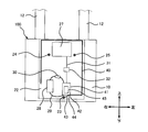
- FIG. 1 is a front view showing a flow rate measuring apparatus 100 according to the first embodiment.
- FIG. 2 is a side view showing the flow rate measuring device 100.
- FIG. 3 is a schematic diagram showing a configuration when the inside of the flow measuring device 100 is viewed from the front.
- FIG. 4 is a schematic diagram showing a configuration when the inside of the flow measuring device 100 is viewed from the side.
- the flow measuring device 100 is a device that transmits data detected by the sensor 11 to a computer of a supplier such as gas, electricity and tap water by wireless communication.
- the flow rate measuring device 100 houses a housing 10 that houses a sensor 11 that measures the flow rate of a fluid, and a configuration for controlling the operation of the sensor 11 and transmitting data detected by the sensor 11 to the outside.
- a housing 20 is provided.
- the housing 10 is made of a conductive material.
- the conductive material include metals such as aluminum and stainless steel, conductive resins, and the like.
- the housing 10 has a substantially rectangular parallelepiped shape, and two pipes 12 for inflow and outflow of an object to be weighed are connected to the upper surface of the housing 10.
- a sensor 11 is accommodated in the housing 10.
- An object to be weighed that flows into the housing 10 from the inflow pipe 12 flows out to the outside through the outflow pipe 12 after the flow rate is detected by the sensor 11.
- Examples of the objects to be weighed include gas, tap water, and electricity.
- the sum of the vertical length: c of the housing 10 and the horizontal length d of the housing 10 is preferably ⁇ / 4.
- ⁇ represents the wavelength of the radio wave radiated from the radiation conductor 40 described later.
- the housing 20 is disposed on the wall surface on the front side of the housing 10 and is formed of a non-conductive material.
- the non-conductive material include resins having electrical insulation properties such as polypropylene and ABS.
- casing 20 has comprised the rectangular parallelepiped shape whose thickness dimension of the front-back direction is small compared with an up-down dimension and a left-right dimension.
- the housing 20 is formed in a front / rear split having a front first housing 21 and a rear second housing 22.
- the rear second housing 22 is attached to the front surface of the housing 10 by, for example, three first to third screws 23 to 25 and first to third nuts.
- the first screw 23 is attached near the center in the left-right direction at the lower part of the second housing 22, and the second screw 24 and the third screw 25 are attached to the left part and the right part of the upper part of the second housing 22. Attached.
- the first to third screws 23 to 25 and the first to third nuts are made of a conductive material. Examples of the conductive material include metals such as aluminum and stainless steel, conductive resins, and the like.
- the screws 23 to 25 penetrate the second housing 22 from the housing 10 side.
- the heads of the screws 23 to 25 appear inside the housing 10, and the legs of the screws 23 to 25 protrude from the surface of the second housing 22.
- Each nut is attached to a leg portion of each screw 23 to 25, and the second housing 22 is fixed to the housing 10.
- the first casing 21 is connected to the second casing 22 so as to cover the second casing 22.
- a display unit 26 is provided on the front surface of the first housing 21. The display unit 26 displays the flow rate of the object to be measured detected by the sensor 11.
- the second casing 22 and the first casing 21 are bonded (bonded) by adhesion, welding, or screws. Thereby, the housing
- casing 20 is sealed and the space which has watertightness is formed in an inside.
- the housing 20 accommodates the radiation conductor 40, the radio communication circuit board 41, the measurement circuit board 27, and the battery 28 in this internal space.
- the housing 10, the second casing 22, the radio communication circuit board 41, the radiation conductor 40, and the first casing 21 are arranged in this order in the thickness direction of the circuit board (that is, the front-rear direction).
- the measurement circuit board 27 includes an integrated circuit (not shown) on which a program is mounted.
- the integrated circuit includes a signal generation circuit that generates a signal to be transmitted based on a detection signal from the sensor 11.
- the flow rate of the measured object such as gas or tap water is acquired based on the detection value from the sensor 11.
- the method for acquiring the measurement value is not particularly limited. For example, if the object to be measured is gas, any known method such as a membrane method or an ultrasonic method may be employed. It is sufficient that a program necessary for calculating the measurement value based on the adopted measurement method is mounted on the integrated circuit.
- the circuit board 41 for wireless communication includes a transmission circuit for transmitting data by wireless communication, a reception circuit for processing data received by non-new communication, and a matching circuit for matching the radiation conductor 40 with these transmission / reception circuits Etc. are mounted on the substrate.
- the wireless communication circuit board 41 is mounted with an integrated circuit 45 that is electrically connected to the radiation conductor 40 and includes a power supply circuit that supplies a high-frequency signal to the radiation conductor 40.
- the integrated circuit 45 for wireless communication is electrically connected to the integrated circuit of the measurement circuit board 27 by the wiring 31 and is electrically connected to the radiation conductor 40. Then, the wireless communication integrated circuit 45 applies a potential to the radiation conductor 40 in accordance with the measurement data from the integrated circuit on the measurement circuit board 27, thereby transmitting a high-frequency signal indicating the measurement data.
- One end of a conducting wire 43 is connected to the ground of the circuit board 41 for wireless communication.
- the other end of the conducting wire 43 is a screw located closest to the radio communication circuit board 41 among the screws 23 to 25 (in this embodiment, the first screw 23 located at the lower portion of the housing 20). Electrically connected.
- the conductive wire 43 is formed of a conductive material such as copper, aluminum, or iron.
- the other end of the conducting wire 43 is wound around the leg portion of the first screw 23 and fixed by the first bolt. Thereby, the conducting wire 43 electrically connects the ground of the circuit board 41 for wireless communication and the first screw 23.
- the first screw 23 is electrically connected to the housing 10.
- wireless communication and the housing 10 are electrically connected through the conducting wire 43 and the screw. Further, the ground of the integrated circuit 45 including the power feeding circuit is connected to the ground of the circuit board 41 for wireless communication. Therefore, the conducting wire 43 and the first screw 23 function as a connecting portion that electrically connects the housing 10 and the ground of the integrated circuit 45 (power feeding circuit) of the circuit board 41 for wireless communication. As a result, the housing 10 has substantially the same potential as the ground of the integrated circuit 45 of the circuit board 41 for wireless communication, and the housing 10 itself having a large area functions as the ground.
- the joint position 44 of the conducting wire 43 and the ground of the circuit board 41 for wireless communication, the conducting wire 43 and the first screw 23 are in the vicinity of a feeding point 42 which will be described later, and to the feeding point 42.
- it is preferably arranged in the direction opposite to the radiation conductor 40. Since the joining position 44 and the first screw 23 are located in the vicinity of the feeding point 42, the distance from the feeding point 42 to the housing 10 is shortened. Further, by arranging the conducting wire 43 on the side opposite to the radiation conductor 40 with respect to the feeding point 42, it is possible to prevent the conducting wire 43 from functioning as a ground when viewed from the radiation conductor 40.
- the battery 28 is a power source that supplies power to electronic components and the like mounted on the circuit board 41 for wireless communication.
- the power supplied from the battery 28 is converted into high-frequency power through the power feeding circuit 45 and supplied to the radiation conductor 40.
- the battery 28 is electrically connected to the power supply circuit of the circuit board 41 by wiring 29 or the like.
- the radiation conductor 40 radiates a high frequency signal modulated by the transmission circuit as a radio wave, or receives an external radio wave (high frequency signal) and passes it to a reception circuit that demodulates the radio wave.
- the radiating conductor 40 according to the present embodiment constitutes an inverted L-type antenna, has a thin rod shape, and is formed of a conductive material such as copper.
- the length of the radiation conductor 40 is set to ⁇ / 4 where ⁇ is the wavelength of the high-frequency signal forming the radio signal.
- the proximal end of the radiating conductor 40 is connected to the output part (feeding terminal) of the circuit board 41 for wireless communication at the feeding point 42.
- the radiating conductor 40 is bent so as to spread in the internal space of the housing 20 so as to be located as far as possible from the housing 10 and so that each part of the radiating conductor 40 is not as close as possible. In this embodiment, for example, it is bent at four places.
- the radiating conductor 40 extends from the feeding point 42 in a direction opposite to the housing 10 (front direction) and is parallel to the housing 10 at a first corner near the front wall portion of the housing 20.
- the radiating conductor 40 extends from the first corner to the left side along the lower surface of the housing 20, and bends upward at a right angle at a second corner near the lower left corner of the housing 20.
- the radiation conductor 40 extends from the second corner upward along the left side surface of the housing 20 and bends to the right at a third corner in the vicinity of the upper left corner of the housing 20.
- the radiation conductor 40 extends along the upper side surface of the housing 20 from the third corner to the right, and bends downward at a right angle at the fourth corner near the upper right corner of the housing 20. And the radiation
- the length from the front surface of the housing 10 to the first corner; a (see FIG. 2) is set as large as possible.
- Length: a is preferably longer than ⁇ / 32, for example.
- the length: a is smaller than ⁇ / 32, the potential difference between the radiation conductor 40 and the housing 10 is small, and it is difficult to radiate radio waves from the radiation conductor 40.
- the radiation conductor 40 from the first corner to the tip is provided in parallel to the front surface of the housing 10. For this reason, the radiation conductor 40 from the first corner to the tip is opposed to the housing 10 with an interval of length: a.
- the object to be weighed flows through the pipe 12 and the sensor 11 detects the flow rate of the non-weighing object.
- the integrated circuit on the weighing circuit board 27 measures the flow rate of the object to be weighed based on the detection value from the sensor 11.
- the integrated circuit 45 of the wireless communication circuit board 41 creates a high-frequency signal according to the measurement value from the integrated circuit of the measurement circuit board 27, and gives this to the radiation conductor 40.
- An electric field is formed between the radiation conductor 40 and the housing 10 (and the pipe line 12) forming the ground, and this electric field changes in accordance with a given high-frequency signal. This change in the electric field becomes a radio wave radiated from the radiation conductor 40.
- the ground of the integrated circuit 45 of the wireless communication circuit board 41 and the housing 10 are electrically connected by the connecting portion constituted by the conductive wire 43 and the first screw 23.
- the housing 10 functions as a ground for the radiation conductor 40. Thereby, it is not necessary to separately provide the ground of the radiation conductor 40 as a dedicated configuration, and the cost of parts can be reduced and the flow measuring device 100 can be downsized.
- the housing 10 has the largest surface area among the components made of the conductive material included in the flow rate measuring device 100. Therefore, if the frequency of the radio wave transmitted and received by the radiation conductor 40 is high, a sufficiently large ground can be secured even for the wavelength. Therefore, the strength of the electric field generated between the radiation conductor 40 and the ground (housing 10) can be improved, and the gain can be improved.
- the sum of the vertical length and the horizontal length of the housing 10: c + d is the same as or close to ⁇ / 4. For this reason, an antenna effective area spreads and an antenna characteristic improves.
- the joint position 44 between the lead wire 43 and the ground of the circuit board 41 for wireless communication, the lead wire 43 and the first screw 23 are located in the vicinity of the feeding point 42. Therefore, since the distance from the feeding point 42 to the housing 10 is shortened, the impedance of the antenna is suppressed to be small, and the antenna characteristics are improved.
- conductive members such as the conductive wires 43 and the first screws 23 that are electrically connected between the radio communication circuit board 41 and the housing 10 forming the ground serve as ground elements with respect to the radiation conductor 40. obtain. When this ground element is close to the radiation conductor 40, the gain of the radiation conductor 40 is reduced.
- the joining position 44 of the conducting wire 43 and the ground of the circuit board 41 for wireless communication, the conducting wire 43 and the first screw 23 are located in the direction opposite to the radiation conductor 40 with respect to the feeding point 42. .
- the ground elements such as the conductive wire 43 and the first screw 23 are provided as far as possible from the radiation conductor 40, it is possible to suppress a decrease in gain.
- the circuit board 41 for wireless communication can also be a small-capacity ground element, but its area is extremely small compared to the housing 10 and is located relatively far from the radiation conductor 40 (particularly from the second corner to the tip). Until the part). Therefore, from the radiation conductor 40, almost all of the ground appears to be constituted by the housing 10, and the radio communication circuit board 41 hardly functions as the ground. That is, many areas of the wireless communication circuit board 41 do not appear as a ground, and the housing 10 functions as a ground. Therefore, since the space
- the radiation conductor 40, the circuit board, and the housing 10 are arranged in this order in the thickness direction of the circuit board. Therefore, since the space
- the thickness of the flow rate measuring device 100 can be reduced by providing the radiation conductor 40, the circuit board, and the housing 10 in parallel with each other.
- the casing 20 is hermetically sealed, the radiation conductor 40, the radio communication circuit board 41, and the like are prevented from being oxidized by air, water, or the like. Therefore, since the change of the impedance of the radiation conductor 40 is prevented, stable antenna characteristics can be maintained.
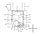
- FIG. 5 is a schematic diagram illustrating a configuration when the inside of the flow rate measuring device 100 according to the second embodiment is viewed from the front.
- the flow measuring device 100 includes a conductive member and a high frequency isolation circuit.
- the conductive member is a member housed in the housing 20 and electrically connected to the wireless communication circuit board 41. Examples of the conductive member include a battery 28, a circuit other than the power feeding circuit, and a circuit board such as the measurement circuit board 27.
- the high frequency isolation circuit is a circuit that electrically insulates (isolates) the integrated circuit 45 (feeding circuit) from the conductive member with respect to the high frequency signal supplied from the radio communication circuit board 41 to the radiation conductor 40.
- the high frequency isolation circuit parallel resonant circuits 30 and 32 that resonate with a high frequency signal and increase impedance are used.
- the parallel resonant circuits 30 and 32 are interposed between the radio communication circuit board 41 and the conductive member described above.
- the resonant frequencies of the parallel resonant circuits 30 and 32 are matched with the frequency of a signal used in wireless communication, that is, the high-frequency signal supplied from the wireless communication circuit board 41 to the radiation conductor 40.
- the inductance and capacitance of the parallel resonant circuits 30 and 32 are set so that the frequency of the high-frequency signal becomes the resonant frequency. For this reason, the parallel resonant circuits 30 and 32 increase the impedance with respect to the high-frequency signal to be used.
- the parallel resonance circuit 30 is connected to the wiring 29 between the battery 28 and the circuit board 41 for wireless communication.
- a direct current flows from the battery 28 to the circuit board 41 for wireless communication, but the battery 28 is cut off from the high frequency signal.
- the parallel resonant circuit 32 is connected to the wiring 31 between the measurement circuit board 27 and the wireless communication circuit board 41.
- a signal is output from the measurement circuit board 27 to the wireless communication circuit board 41, but the measurement circuit board 27 is blocked from high-frequency signals.
- the battery 28 and the measuring circuit board 27 do not appear as the ground of the radiation conductor 40 and do not become a resistance component against the electric field generated between the radiation conductor 40 and the housing 10. For this reason, this electric field is not attenuated by the battery 28 and the measuring circuit board 27, and the deterioration of the antenna characteristics due to the battery 28 and the measuring circuit board 27 is suppressed. That is, an ideal circuit is configured by the radiation conductor 40, the wireless communication circuit 41, and the housing 10 that functions as the ground of the radiation conductor 40.
- the parallel resonant circuits 30 and 32 are used as the high frequency isolation circuit.
- a photocoupler 51 is used as a high-frequency isolation circuit.
- a parallel resonant circuit may be used as a high-frequency isolation circuit for a conductive member that cannot use the photocoupler 51 such as a battery.
- FIG. 6 is a schematic diagram illustrating a configuration when the inside of the flow rate measuring device 100 according to Embodiment 3 is viewed from the front.
- a photocoupler 51 is used as a high-frequency isolation circuit related to the measurement circuit board 27.
- the photocoupler 51 is mounted on the wireless communication circuit board 41 and connected to the wiring 31.
- the photocoupler 51 is interposed between the integrated circuit 45 (power feeding circuit) and a conductive member such as the measurement circuit board 27.
- the photocoupler 51 includes a light emitting element and a light receiving element, and transmits an electrical signal by light.
- the photocoupler 51 converts an electrical signal from the integrated circuit on the measuring circuit board 27 into light, and emits the light with a light emitting element.
- the photocoupler 51 receives this light with the light receiving element, converts the light into an electric signal, and outputs the electric signal to the integrated circuit 45.
- the photocoupler 51 does not directly exchange electrical signals between the integrated circuit 45 of the wireless communication circuit board 41 and the integrated circuit of the measurement circuit board 27. As a result, the photocoupler 51 electrically isolates the integrated circuit 45 from the measurement circuit board 27 with respect to the high-frequency signal supplied from the radio communication circuit board 41.
- the measurement circuit board 27 is not seen as the ground of the radiation conductor 40, but is ideally formed by the radiation conductor 40, the wireless communication circuit 41, and the housing 10 that functions as the ground of the radiation conductor 40. Circuit is constructed.
- a pipe (conductive pipe) 14 and a pipe part (non-conductive pipe) 13 are further provided in the flow rate measuring apparatus 100 according to the first embodiment.
- FIG. 7 is a front view showing the flow rate measuring apparatus 100 according to the fourth embodiment.
- the flow rate measuring device 100 includes a pipe 14 and a pipe part 13.
- the pipe 14 is made of a conductive material.
- the conductive material is formed of a metal such as aluminum or a conductive resin.
- One end of the pipe 14 is connected to an inlet or an outlet formed on the upper surface of the housing 10.
- the other end of the pipe 14 is connected to the pipe part 13.
- the length of the pipe 14: e is set based on the antenna gain. That is, one of the factors that change the gain of the radiation conductor 40 is the ground size.
- the ground size is determined according to the dimensions of the ground element including the housing 10 and the pipe 14 made of a conductive member. Therefore, the gain of the radiation conductor 40 can be improved by setting the dimension of the pipe 14 to an appropriate length.
- the pipe 14 since the pipe 14 is electrically connected to the housing 10, the pipe 14 functions as a ground for the radiation conductor 40 together with the housing 10.
- the high-frequency signal from the radio communication circuit board 41 is transmitted in the axial direction of the pipe 14 through the housing 10. Therefore, there is a length 14e of the pipe 14 suitable for the wavelength of the high-frequency signal that increases the antenna gain.
- the pipe part 13 is connected to the pipe 14 so that the length of the pipe 14 is e.
- the pipe portion 13 is connected to the pipe 14 and is formed of a nonconductive material.
- the non-conductive material include resins having electrical insulation properties such as polypropylene and ABS.
- the pipe portion 13 is interposed between the pipe 14 and the pipe line 12 to prevent a high frequency signal from being transmitted from the pipe 14 to the pipe line 12.
- the pipe 14 is connected to the housing 10, and the pipe portion 13 electrically insulates the pipe 14 and the pipe line 12.
- the housing 10 and the piping 14 function as the ground of the radiation conductor 40, and the ground can be increased with respect to the wavelength of the high-frequency signal.
- the antenna gain can be further improved by adjusting the length of the pipe 14: e so that the antenna gain is increased.
- the size of the ground formed by the conductive member housing 10 and the pipe 14 can be defined (defined) by the tube portion 13 of the nonconductive member so that the radiation conductor 40 has a high gain.
- the radiating conductor 40 of the inverted L antenna is used.
- the radiating conductor 40 may be composed of other linear conductor elements. Examples of the linear conductor element include a loop antenna or a meander line antenna.
- a linear conductor element is used for the radiation conductor 40, but the radiation conductor 40 may be composed of other conductor elements.
- a planar conductor element such as a plate-like inverted F antenna, a linear inverted L antenna, or a plate-like dipole antenna may be used as the radiation conductor 40.
- the metal foil wiring 29 on the circuit board may be used for the radiation conductor 40.
- the conductive wire 43 and the first screw 23 are used as a connection portion for electrically connecting the radio communication circuit board 41 and the housing 10.
- a connection part is not limited to these.
- a hole is formed in the second housing 22, and the wireless communication circuit board 41 is fitted into the hole.
- wireless communication is arrange
- the conductive adhesive functions as a connection portion, and the radio communication circuit board 41 is electrically connected to the housing 10. At this time, the periphery of the hole is sealed so that the inside of the housing 20 is sealed.
- the joining of the radiation conductor 40 and the output portion of the wireless communication circuit board 41 and the joining of the ground of the wireless communication circuit board 41 and the conductive wire 43 were performed by solder.
- the joining method is not limited to this as long as they are electrically joined. For example, these may be joined via screws or connectors.
- an ultrasonic gas meter may be used for the flow rate measuring device 100.
- the housing 10 since the housing 10 is small, the effective length of the antenna can be increased by changing the shape of the housing 10. Thereby, the antenna gain can be improved.
- the housing 10 since the housing 10 is small, it is possible to secure a large distance between the radiation conductor 40 and the housing 10 (ground), and an improvement in gain can be expected.
- the flow rate measuring device according to the present invention is useful as a small flow rate measuring device with improved antenna characteristics as compared with the prior art.
Landscapes
- Physics & Mathematics (AREA)
- General Physics & Mathematics (AREA)
- Fluid Mechanics (AREA)
- Measuring Volume Flow (AREA)
- Details Of Flowmeters (AREA)
Abstract
流量計測装置(100)は、導電性材料で形成され、かつ被計量物の流量を検出するセンサ(11)を収容するためのハウジング(10)と、高周波信号を成す電波を放射する放射導体(40)と、前記放射導体と電気的に接続され、かつ前記高周波信号を形成する高周波電力を前記放射導体に供給する給電回路(45)が搭載された回路基板(41)と、非導電性材料で形成され、前記ハウジング上に配され、かつ前記放射導体および前記回路基板を収容する筐体(20)と、導電性材料で形成され、かつ前記ハウジングと前記給電回路のグランドとを電気的に接続する接続部(23,43)と、を備える。
Description
本発明は、流量計測装置に関し、特に、被計量物の流量を計測する流量計測装置に関する。
近年、家屋などの建造物に設置された流量計測装置でガス、電気、水道などの使用量を計測し、この計測データを無線通信によって収集する自動検針システムが導入されている。このような自動検針システムでは、設置しやすさなどの観点から小型の流量計測装置が求められている。
このような流量計測装置として、たとえば、ガスメータの表面に無線アダプタ子機が取り付けられたものが提案されている(特許文献1参照)。この特許文献1に記載の無線アダプタ子機には、基板実装形板状アンテナが内蔵されている。基板実装形板状アンテナでは、接地導体板と放射導体部の短絡導体とがプリント回路基板の配線パターンを介して接続されている。この接地導体板が、放射導体部のグラウンドとして利用されている。
しかし、従来技術では、接地導体部のサイズが無線通信に用いる高周波信号の波長に対して必ずしも十分に大きいとはいえず、周囲に存在する金属の影響を接地導体部が受ける。これにより、利得や放射効率などのアンテナ特性が低下してしまう。
これに対して、接地導体部のサイズを大きくしようとすると、無線アダプタ子機のサイズが大型化してしまう。
また、接地導体板が放射導体部のグランド専用の構成として設けられているため、無線アダプタ子機のサイズが大きくなってしまう。
本発明は、上述した問題を解決するためになされたものであり、従来技術に比べ、アンテナ特性の向上を図った、小型の流量計測装置を提供することを目的とする。
本発明のある態様に係る、流量計測装置は、導電性材料で形成され、かつ被計量物の流量を検出するセンサを収容するためのハウジングと、高周波信号を成す電波を放射する放射導体と、前記放射導体と電気的に接続され、かつ前記高周波信号を形成する高周波電力を前記放射導体に供給する給電回路が搭載された回路基板と、非導電性材料で形成され、前記ハウジング上に配され、かつ前記放射導体および前記回路基板を収容する筐体と、導電性材料で形成され、かつ前記ハウジングと前記回路基板のグランドとを電気的に接続する接続部と、を備える。
本発明は、以上に説明した構成を有し、従来技術に比べ、アンテナ特性の向上を図った、小型の流量計測装置を提供することができるという効果を奏する。
本発明の上記目的、他の目的、特徴、及び利点は、添付図面参照の下、以下の好適な実施態様の詳細な説明から明らかにされる。
本発明のある実施の態様に係る、流量計測装置は、導電性材料で形成され、かつ被計量物の流量を検出するセンサを収容するためのハウジングと、高周波信号を成す電波を放射する放射導体と、前記放射導体と電気的に接続され、かつ前記高周波信号を形成する高周波電力を前記放射導体に供給する給電回路が搭載された回路基板と、非導電性材料で形成され、前記ハウジング上に配され、かつ前記放射導体および前記回路基板を収容する筐体と、導電性材料で形成され、かつ前記ハウジングと前記給電回路のグランドとを電気的に接続する接続部と、を備える。
流量計測装置は、前記筐体に収容され、かつ前記給電回路と電気的に接続される導電部材と、前記給電回路と前記導電部材との間に介在し、かつ前記高周波信号に関して前記給電回路を前記導電部材から電気的に隔離する高周波隔離回路と、をさらに備えていてもよい。
流量計測装置では、前記高周波隔離回路は、前記高周波信号に共振してインピーダンスが増大する並列共振回路を含んでいてもよい。
流量計測装置では、前記高周波隔離回路は、前記給電回路を前記導電部材から電気的に絶縁するフォトカプラを含んでいてもよい。
流量計測装置では、前記回路基板は、前記給電回路と前記放射導体とを電気的に接続する給電点を有し、前記接続部は、前記給電点の近傍であり、かつ前記給電点に対して前記放射導体とは反対側の位置に配置されてもよい。
流量計測装置は、導電性材料で形成され、かつ前記ハウジングに電気的に接続される導電性配管と、非導電性材料で形成され、かつ前記導電性配管に連結される非導電性配管と、をさらに備え、前記導電性配管の長さが、前記放射導体が有するアンテナ利得に基づいて設定されてもよい。
以下、本発明の実施の形態を、図面を参照しながら具体的に説明する。
なお、以下では全ての図面を通じて同一又は相当する要素には同一の参照符号を付して、その重複する説明を省略する。
また、説明の便宜上、各図に示すように、「前」、「後」、「上」、「下」、「右」、「左」とする。即ち、ハウジング10に対して筐体20が位置する方向を「前」とし、そのた反対を「後」とする。そして、前方を向いた状態を基準として、「右」および「左」を規定する。更に、鉛直方向の上下を夫々「上」および「下」と規定する。
(実施の形態1)
図1は、実施の形態1に係る流量計測装置100を示す正面図である。図2は、流量計測装置100を示す側面図である。図3は、流量計測装置100の内部を正面から見たときの構成を示す模式図である。図4は、流量計測装置100の内部を側方から見たときの構成を示す模式図である。
図1は、実施の形態1に係る流量計測装置100を示す正面図である。図2は、流量計測装置100を示す側面図である。図3は、流量計測装置100の内部を正面から見たときの構成を示す模式図である。図4は、流量計測装置100の内部を側方から見たときの構成を示す模式図である。
流量計測装置100は、たとえば、センサ11により検出されたデータを無線通信でガス、電気および水道水などの供給業者のコンピュータに送信する装置である。
流量計測装置100は、流体の流量を計測するセンサ11を収容するハウジング10、および、該センサ11の動作を制御したり該センサ11が検出したデータを外部へ送信したりするための構成を収容する筐体20を備える。
ハウジング10は、導電性材料で形成される。導電性材料としては、たとえば、アルミニウムやステンレスなどの金属、導電性樹脂などが挙げられる。
ハウジング10は、略直方体形状を成しており、その上面に、被計量物の流入用と流出用の2本の管路12が接続されている。ハウジング10内にはセンサ11が収容されている。流入用の管路12からハウジング10内に流入した被計量物は、当該センサ11によってその流量が検出された後、流出用の管路12を通じて外部へ流出する。被計量物としては、たとえば、ガス、水道水および電気などが挙げられる。
ハウジング10は、その上下方向の長さ:cと、ハウジング10の左右方向の長さ:dとの和が、λ/4であることが好ましい。λは、後述する放射導体40から放射される電波の波長を表す。
筐体20は、ハウジング10の正面側の壁面上に配され、非導電性材料で形成される。非導電性材料としては、たとえば、ポリプロピレンやABSなど電気絶縁性を有する樹脂が挙げられる。筐体20は、上下寸法や左右寸法に比べて前後方向の厚み寸法が小さい直方体形状を成している。また、筐体20は、前側の第1筐体21および後ろ側の第2筐体22を有する前後割りに形成されている。
後ろ側の第2筐体22は、たとえば3つの第1~第3ビス23~25および第1~第3ナットによりハウジング10の前面に取り付けられる。例えば、第1ビス23は、第2筐体22の下部の左右方向中央付近にて取り付けられ、第2ビス24および第3ビス25は、第2筐体22の上部の左部分および右部分にて取り付けられる。第1~第3ビス23~25および第1~第3ナットは、導電性材料で形成される。導電性材料としては、たとえば、アルミニウムやステンレスなどの金属、導電性樹脂などが挙げられる。各ビス23~25は、ハウジング10側から第2筐体22を貫通する。各ビス23~25の頭部はハウジング10の内部に現れ、各ビス23~25の脚部は第2筐体22の表面から突き出る。各ビス23~25の脚部に各ナットが取り付けられ、第2筐体22がハウジング10に固定される。
第1筐体21は、第2筐体22を覆うようにして該第2筐体22に接続される。第1筐体21の前面に表示部26が設けられる。表示部26には、センサ11が検出した被計量物の流量などが表示される。
第2筐体22と第1筐体21とが接着、溶着またはビスなどで結合(接合)される。これにより、筐体20は密閉されて水密性を有する空間が内部に形成される。筐体20は、この内部空間に、放射導体40、無線通信用回路基板41、計量用回路基板27およびバッテリ28を収容する。ハウジング10、第2筐体22、無線通信用回路基板41、放射導体40および第1筐体21は、回路基板の厚み方向(即ち、前後方向)にこの順で配置される。
計量用回路基板27はプログラムが実装された集積回路(図示せず)を備える。集積回路は、センサ11からの検知信号に基づいて、伝送すべき信号を生成する信号生成回路を含む。この集積回路がプログラムに基づいて動作することにより、センサ11からの検出値に基づいて、ガスや水道水などの被計測物の流量が取得される。計測値の取得方法は、特に限定されない。たとえば、計量対象がガスであれば、膜式や超音波式など公知の何れの方法を採用してもよい。この採用した計量方法に基づいて計量値を算出するのに必要なプログラムが集積回路に実装されていればよい。
無線通信用回路基板41は、無線通信によりデータを送信するための送信回路、無新通信により受信したデータを処理するための受信回路、および、放射導体40とこれら送受信回路とを整合させる整合回路等が基板に搭載された構成となっている。無線通信用回路基板41は、放射導体40と電気的に接続され、かつ高周波信号を放射導体40に供給する給電回路を含む集積回路45が搭載される。無線通信用の集積回路45は、計量用回路基板27の集積回路と配線31により電気的に接続され、放射導体40と電気的に接続される。そして、無線通信用の集積回路45は、計量用回路基板27の集積回路からの計量データに応じて放射導体40に電位を付与することにより、該計量データを示す高周波信号を発信する。
無線通信用回路基板41のグランドには、導線43の一端が接続される。また、導線43の他端は、ビス23~25のうち、無線通信用回路基板41の最も近くに位置するビス(本実施の形態では、筐体20の下部に位置する第1ビス23)に電気的に接続されている。この導線43は、例えば銅、アルミニウム、鉄などの導電性材料で形成される。なお、この実施例では、導線43の他端は第1ビス23の脚部に巻き付けられて、第1ボルトにより固定される。これにより、導線43は、無線通信用回路基板41のグランドと第1ビス23とを電気的に接続する。この第1ビス23はハウジング10と電気的に接続されている。このため、無線通信用回路基板41のグランドとハウジング10とは導線43およびビスを介して電気的に接続される。また、給電回路を含む集積回路45のグランドが無線通信用回路基板41のグランドと接続する。よって、導線43および第1ビス23は、ハウジング10と無線通信用回路基板41の集積回路45(給電回路)のグランドとを電気的に接続する接続部として機能する。これにより、ハウジング10は、無線通信用回路基板41の集積回路45のグランドとほぼ同電位となり、広い面積を有するハウジング10自体がグランドとして機能する。
なお、図3に示すように、導線43と無線通信用回路基板41のグランドとの接合位置44、導線43および第1ビス23は、後述する給電点42の近傍であり、かつ給電点42に対して、放射導体40とは反対の方向に配置されるのが好ましい。この接合位置44および第1ビス23が給電点42の近傍に位置することにより、給電点42からハウジング10までの距離が短くなる。また、導線43を給電点42に対して放射導体40とは反対側に配設することにより、導線43が放射導体40から見てグランドとして機能するのを防止できる。
バッテリ28は、無線通信用回路基板41に実装される電子部品などに電力を供給する電源である。特に、バッテリ28から供給された電力は、給電回路45を通じて高周波電力に変換され、放射導体40へ供給される。このバッテリ28は、配線29などにより回路基板41の給電回路と電気的に接続される。
放射導体40は、送信回路にて変調された高周波信号を、電波として放射したり、外部からの電波(高周波信号)を受信して、これを復調する受信回路に受け渡す。本実施の形態に係る放射導体40は、逆L型アンテナを構成するものであり、細い棒形状を有し、銅などの導電性材料で形成される。放射導体40の長さは、無線信号を成す高周波信号の波長をλとした場合に、λ/4に設定される。
放射導体40の基端は給電点42において無線通信用回路基板41の出力部(給電端子)と接続される。放射導体40は、ハウジング10からなるべく離れて位置するように、かつ、放射導体40の各部がなるべく近接しないように、筐体20の内部空間において広がるように折り曲げられる。この実施例では、たとえば、4箇所で折り曲げられる。
具体的に説明すると、放射導体40は、給電点42から、ハウジング10と反対の方向(前の方向)に延び、筐体20の前壁部近傍の第1角で、ハウジング10と平行な方向に曲がる。放射導体40は、第1角から左の方向へ、筐体20の下側面に沿って延び、筐体20の左下の角部近傍の第2角で、直角に上方へ曲がる。放射導体40は、第2角から上の方向へ、筐体20の左側面に沿って延び、筐体20の左上の角部近傍の第3角で直角に右へ曲がる。放射導体40は、第3角から右の方向へ、筐体20の上側面に沿って延び、筐体20の右上の角部近傍の第4角で直角に下方へ曲がる。そして、放射導体40は、第4角から下方へは、筐体20の右側面に沿って延びて先端へと至る。
ハウジング10の前面から第1角までの長さ;a(図2参照)は、できる限り大きく設定される。長さ:aは、たとえば、λ/32より長いことが好ましい。長さ:aがλ/32より小さいと、放射導体40とハウジング10との間で電位差が小さく、放射導体40から電波を放射しにくい。第1角から先端までの放射導体40は、ハウジング10の前面に対して平行に設けられる。このため、第1角から先端までの放射導体40は、長さ:aの間隔を隔ててハウジング10に対向する。
上記構成の流量計測装置100では、被計量物が管路12を流れ、センサ11が非計量物の流量を検出する。計量用回路基板27の集積回路がセンサ11からの検出値に基づいて被計量物の流量を計測する。無線通信用回路基板41の集積回路45は、計量用回路基板27の集積回路からの計測値に応じて高周波信号を作成して、これを放射導体40に与える。放射導体40とそのグランドを成すハウジング10(及び管路12)との間には電界が形成され、この電界は、与えられた高周波信号に応じて変化する。この電界の変化が、放射導体40から放射される電波となる。
上記構成の流量計測装置100によれば、導線43および第1ビス23から構成される接続部により、無線通信用回路基板41の集積回路45のグランドとハウジング10とが電気的に接続される。このため、ハウジング10は、放射導体40のグランドとして機能する。これにより、放射導体40のグランドを別途専用の構成として設ける必要がなく、部品のコストの削減および流量計測装置100の小型化が図られる。
また、ハウジング10は、流量計測装置100が備える導電性材料から成る構成物の中でも最も表面積が大きい。従って、放射導体40により送受信される電波の周波数が高ければ、その波長に対しても十分な大きさのグランドを確保することができる。よって、放射導体40とグランド(ハウジング10)との間で生成される電界の強度を向上することができ、利得の向上を図ることができる。
さらに、ハウジング10の上下方向の長さと左右方向の長さとの和:c+dがλ/4と同じまたは近い。このため、アンテナ実効面積が広がり、アンテナ特性が向上する。
また、導線43と無線通信用回路基板41のグランドとの接合位置44、導線43および第1ビス23は、給電点42の近傍に位置する。これにより、給電点42からハウジング10までの距離が短くなるため、アンテナのインピーダンスが小さく抑えられ、アンテナ特性が向上する。
また、導線43や第1ビス23など、無線通信用回路基板41とグランドを成すハウジング10との間に介在して電気的に接続された導電性部材は、放射導体40に対してグランド要素となり得る。このグランド要素が放射導体40に近接すると、放射導体40の利得は低下してしまう。しかしながら、本実施の形態では、導線43と無線通信用回路基板41のグランドとの接合位置44、導線43および第1ビス23は、給電点42に対し、放射導体40と反対の方向に位置する。このように、導線43や第1ビス23等のグランド要素は、放射導体40から極力離して設けられているため、利得の低下を抑制することができる。
また、無線通信用回路基板41も小容量のグランド要素となり得るが、その面積はハウジング10に比べて極めて小さく、しかも放射導体40から比較的離れて位置している(特に、第2角から先端までの部分)。そのため、放射導体40からは、グランドのほぼ全てはハウジング10から構成されているように見え、無線通信用回路基板41はグランドとしてほとんど機能しない。即ち、無線通信用回路基板41の多くの範囲はグランドとしてみえず、ハウジング10がグランドとして機能する。よって、放射導体40と、広い面積を有するグランド(ハウジング10)との間隔が大きくなるため、アンテナ特性が優れる。
さらに、放射導体40、回路基板およびハウジング10が回路基板の厚み方向にこの順で配される。これにより、放射導体40とハウジング10との間隔が大きくなるため、アンテナの周波数帯域幅が広くなり、アンテナ特性が優れる。
また、放射導体40、回路基板およびハウジング10を互いに平行に設けることにより、流量計測装置100の厚みを小さくすることができる。
さらに、筐体20が密閉されているため、空気や水などにより放射導体40や無線通信用回路基板41などが酸化されることが抑制される。よって、放射導体40のインピーダンスの変化が防がれるため、安定したアンテナの特性を維持することができる。
(実施の形態2)
実施の形態2の流量計測装置100は、実施の形態1の流量計測装置100に並列共振回路30、32がさらに設けられている。
実施の形態2の流量計測装置100は、実施の形態1の流量計測装置100に並列共振回路30、32がさらに設けられている。
図5は、実施の形態2に係る流量計測装置100の内部を正面から見たときの構成を示す模式図である。
流量計測装置100は、導電部材および高周波隔離回路を備える。導電部材は、筐体20に収容され、かつ無線通信用回路基板41と電気的に接続される部材である。導電部材としては、たとえば、バッテリ28、給電回路以外の回路、および計量用回路基板27などの回路基板などが挙げられる。
高周波隔離回路は、無線通信用回路基板41から放射導体40に供給される高周波信号に関し集積回路45(給電回路)を導電部材から電気的に絶縁(隔離)する回路である。高周波隔離回路として、高周波信号に共振してインピーダンスが増大する並列共振回路30、32が用いられる。並列共振回路30、32は、無線通信用回路基板41と上述した導電部材との間に介在する。並列共振回路30、32の共振周波数は、無線通信で用いる信号の周波数、即ち、無線通信用回路基板41から放射導体40に供給される高周波信号に合わせられる。換言すれば、並列共振回路30、32のインダクタンス及びキャパシタンスは、高周波信号の周波数が共振周波数となるように設定される。このため、並列共振回路30、32は、使用する高周波信号に対してインピーダンスを大きくする。
上記構成の流量計測装置100によれば、たとえば、並列共振回路30は、バッテリ28と無線通信用回路基板41との間の配線29に接続される。これにより、バッテリ28から無線通信用回路基板41に直流電流が流れるが、バッテリ28は、高周波信号に対して遮断される。また、並列共振回路32は、計量用回路基板27と無線通信用回路基板41との間の配線31に接続される。これにより、計量用回路基板27から無線通信用回路基板41に信号が出力されるが、計量用回路基板27は高周波信号に対して遮断される。
その結果、バッテリ28および計量用回路基板27は、放射導体40のグランドとみえず、放射導体40とハウジング10との間に発生する電界に対して抵抗成分とならない。このため、この電界がバッテリ28および計量用回路基板27により減衰されず、バッテリ28および計量用回路基板27に起因するアンテナ特性の劣化が抑えられる。つまり、放射導体40と、無線通信回路41と、放射導体40のグランドとして機能するハウジング10とにより、理想的な回路が構成される。
なお、バッテリ28および計量用回路基板27以外にも、放射導体40に対してグランド要素となり得る導電部材であって、かつグランドとして機能するのが好ましくない導電部材が存在する場合には、上記のような並列共振回路30、32を介在させればよい。
(実施の形態3)
実施の形態2では高周波隔離回路として並列共振回路30、32が用いられた。これに対し、実施の形態3では高周波隔離回路としてフォトカプラ51が用いられる。なお、バッテリなどフォトカプラ51を用いることができない導電部材に対しては、並列共振回路が高周波隔離回路として用いられてもよい。
実施の形態2では高周波隔離回路として並列共振回路30、32が用いられた。これに対し、実施の形態3では高周波隔離回路としてフォトカプラ51が用いられる。なお、バッテリなどフォトカプラ51を用いることができない導電部材に対しては、並列共振回路が高周波隔離回路として用いられてもよい。
図6は、実施の形態3に係る流量計測装置100の内部を正面から見たときの構成を示す模式図である。
計量用回路基板27に関する高周波隔離回路として、フォトカプラ51が用いられる。フォトカプラ51は、無線通信用回路基板41上に搭載され、配線31に接続される。フォトカプラ51は、集積回路45(給電回路)と計量用回路基板27などの導電部材との間に介在する。フォトカプラ51は、発光素子および受光素子を含み、光により電気信号を伝達する。フォトカプラ51は、計量用回路基板27の集積回路からの電気信号を光に変換し、この光を発光素子で放つ。そして、フォトカプラ51は、この光を受光素子で受け、光を電気信号に変換し、電気信号を集積回路45へ出力する。このように、フォトカプラ51によって無線通信用回路基板41の集積回路45と計量用回路基板27の集積回路との間で電気信号のやり取りが直接行われていない。これにより、フォトカプラ51は、無線通信用回路基板41から供給される高周波信号に関し集積回路45を計量用回路基板27から電気的に隔離する。
上記構成の流量計測装置100によれば、計量用回路基板27は放射導体40のグランドとみえず、放射導体40と、無線通信回路41と、放射導体40のグランドとして機能するハウジング10とにより、理想的な回路が構成される。
(実施の形態4)
実施の形態4の流量計測装置100は、実施の形態1の流量計測装置100に配管(導電性配管)14および管部(非導電性配管)13がさらに設けられている。
実施の形態4の流量計測装置100は、実施の形態1の流量計測装置100に配管(導電性配管)14および管部(非導電性配管)13がさらに設けられている。
図7は、実施の形態4に係る流量計測装置100を示す正面図である。
流量計測装置100は、配管14および管部13を備える。
ハウジング10に、たとえば、2本の配管14が接続される。配管14は導電性材料で形成される。導電性材料としては、アルミニウムなどの金属、導電性樹脂などで形成される。配管14の一端は、ハウジング10上面に形成された流入口または流出口に接続される。配管14の他端は、管部13に接続される。
配管14の長さ:eは、アンテナ利得に基づいて設定される。すなわち、放射導体40の利得を変動させる要因の一つにはグランドサイズがある。グランドサイズは、導電部材から成るハウジング10及び配管14を含むグランド要素の寸法に応じて決定される。従って、配管14の寸法を適宜の長さとすることにより、放射導体40の利得を向上することができる。換言すれば、配管14はハウジング10と電気的に接続されるため、配管14はハウジング10と共に放射導体40のグランドとして機能する。このとき、無線通信用回路基板41からの高周波信号はハウジング10を介して配管14の軸方向に伝わる。よって、アンテナ利得が大きくなるような、高周波信号の波長に対して適した配管14の長さ:eがある。この配管14の長さ:eになるように、管部13が配管14に接続される。
管部13は、配管14に連結され、かつ非導電性材料で形成される。非導電性材料としては、ポリプロピレンやABSなど電気絶縁性を有する樹脂が挙げられる。管部13は、配管14と管路12との間に介在して、配管14から管路12に高周波信号が伝わることを防ぐ。
上記構成の流量計測装置100によれば、配管14がハウジング10に接続され、管部13が配管14と管路12とを電気的に絶縁する。これにより、ハウジング10および配管14が放射導体40のグランドとして機能し、高周波信号の波長に対してグランドを大きくすることができる。
さらに、配管14の長さ:eをアンテナ利得が大きくなるように調整することにより、アンテナ利得のさらなる向上が図れる。換言すれば、非導電部材の管部13により、導電部材のハウジング10及び配管14から成るグランドのサイズを、放射導体40が高利得となるように規定(画定)することができる。
なお、上記全ての実施の形態では、逆L型アンテナの放射導体40が用いられたが、放射導体40はこれ以外の線状の導体素子で構成され得る。線状の導体素子としては、たとえば、ループアンテナまたはメアンダラインアンテナなどが挙げられる。
さらに、上記全ての実施の形態では、放射導体40に線状の導体素子が用いられたが、放射導体40はこれ以外の導体素子で構成され得る。たとえば、板状逆Fアンテナ、線状逆Lアンテナ、板状のダイポールアンテナなどの平面状の導体素子が放射導体40として用いられてもよい。また、回路基板上の金属箔の配線29が放射導体40に用いられてもよい。
また、上記全ての実施の形態では、無線通信用回路基板41とハウジング10とを電気的に接続する接続部として、導線43および第1ビス23が用いられた。接続部はこれらに限定されない。たとえば、第2筐体22に孔が開けられており、この孔の中に無線通信用回路基板41が嵌められる。これにより、無線通信用回路基板41がハウジング10上に直接配置され、無線通信用回路基板41は導電性接着剤でハウジング10に取り付けられる。この導電性接着剤が接続部として機能し、無線通信用回路基板41はハウジング10と電気的に接続される。このとき、筐体20の内部が密閉されるように、孔の周囲がシールされる。
さらに、上記全ての実施の形態では、放射導体40と無線通信用回路基板41の出力部との接合、および無線通信用回路基板41のグランドと導線43との接合は、半田により行われた。ただし、接合方法は、これらが電気的に接合されていれば、これに限定されない。たとえば、これらがビスやコネクタなどを介して接合されてもよい。
また、上記全ての実施の形態において、超音波式ガスメータ(USM)が流量計測装置100に用いられてもよい。この場合、ハウジング10が小さいため、ハウジング10の形状を変化させることにより、アンテナの実効長を長くすることができる。これにより、アンテナ利得の向上が図れる。あるいは、ハウジング10が小さいため、その分、放射導体40とハウジング10(グランド)との間の距離を大きく確保することができ、利得の向上を期待することができる。
上記説明は、例示としてのみ解釈されるべきであり、本発明は実行する最良の態様を当業者に教示する目的で提供されたものである。本発明の精神を逸脱することなくその構造及び/又は機能の詳細を実質的に変更できる。
以上のように、本発明にかかる流量計測装置は、従来技術に比べ、アンテナ特性の向上を図った、小型の流量計測装置として有用である。
10 ハウジング
11 センサ
13 管部(非導電性配管)
14 配管(導電性配管)
20 筐体
23 第1ビス(接続部)
28 バッテリ(導電部材)
27 計量用回路基板(導電部材)
30 並列共振回路(高周波隔離回路)
32 並列共振回路(高周波隔離回路)
40 放射導体
41 無線通信用回路基板(回路基板)
43 導線(接続部)
42 給電点
45 集積回路(給電回路)
51 フォトカプラ(高周波隔離回路)
11 センサ
13 管部(非導電性配管)
14 配管(導電性配管)
20 筐体
23 第1ビス(接続部)
28 バッテリ(導電部材)
27 計量用回路基板(導電部材)
30 並列共振回路(高周波隔離回路)
32 並列共振回路(高周波隔離回路)
40 放射導体
41 無線通信用回路基板(回路基板)
43 導線(接続部)
42 給電点
45 集積回路(給電回路)
51 フォトカプラ(高周波隔離回路)
Claims (6)
- 導電性材料で形成され、かつ被計量物の流量を検出するセンサを収容するためのハウジングと、
高周波信号を成す電波を放射する放射導体と、
前記放射導体と電気的に接続され、かつ前記高周波信号を形成する高周波電力を前記放射導体に供給する給電回路が搭載された回路基板と、
非導電性材料で形成され、前記ハウジング上に配され、かつ前記放射導体および前記回路基板を収容する筐体と、
導電性材料で形成され、かつ前記ハウジングと前記給電回路のグランドとを電気的に接続する接続部と、を備える、流量計測装置。 - 前記筐体に収容され、かつ前記給電回路と電気的に接続される導電部材と、
前記給電回路と前記導電部材との間に介在し、かつ前記高周波信号に関して前記給電回路を前記導電部材から電気的に隔離する高周波隔離回路と、をさらに備える、請求項1に記載の流量計測装置。 - 前記高周波隔離回路は、前記高周波信号に共振してインピーダンスが増大する並列共振回路を含む、請求項2に記載の流量計測装置。
- 前記高周波隔離回路は、前記給電回路を前記導電部材から電気的に絶縁するフォトカプラを含む、請求項2に記載の流量計測装置。
- 前記回路基板は、前記給電回路と前記放射導体とを電気的に接続する給電点を有し、
前記接続部は、前記給電点の近傍であり、かつ前記給電点に対して前記放射導体とは反対側の位置に配置される、請求項1~4のいずれか一項に記載の流量計測装置。 - 導電性材料で形成され、かつ前記ハウジングに電気的に接続される導電性配管と、
非導電性材料で形成され、かつ前記導電性配管に連結される非導電性配管と、をさらに備え、
前記導電性配管の長さが、前記放射導体が有するアンテナ利得に基づいて設定される、請求項1~5のいずれか一項に記載の流量計測装置。
Priority Applications (2)
| Application Number | Priority Date | Filing Date | Title |
|---|---|---|---|
| ES13767755T ES2758924T3 (es) | 2012-03-29 | 2013-03-26 | Aparato de medición de volumen de flujo |
| EP13767755.5A EP2833476B1 (en) | 2012-03-29 | 2013-03-26 | Flow volume measuring apparatus |
Applications Claiming Priority (2)
| Application Number | Priority Date | Filing Date | Title |
|---|---|---|---|
| JP2012-076600 | 2012-03-29 | ||
| JP2012076600 | 2012-03-29 |
Publications (1)
| Publication Number | Publication Date |
|---|---|
| WO2013145720A1 true WO2013145720A1 (ja) | 2013-10-03 |
Family
ID=49259019
Family Applications (1)
| Application Number | Title | Priority Date | Filing Date |
|---|---|---|---|
| PCT/JP2013/002051 Ceased WO2013145720A1 (ja) | 2012-03-29 | 2013-03-26 | 流量計測装置 |
Country Status (3)
| Country | Link |
|---|---|
| EP (1) | EP2833476B1 (ja) |
| ES (1) | ES2758924T3 (ja) |
| WO (1) | WO2013145720A1 (ja) |
Cited By (2)
| Publication number | Priority date | Publication date | Assignee | Title |
|---|---|---|---|---|
| WO2015122157A1 (ja) * | 2014-02-14 | 2015-08-20 | パナソニックIpマネジメント株式会社 | 流量計測装置および無線通信装置 |
| JP2017509245A (ja) * | 2014-03-07 | 2017-03-30 | ゼネラル・エレクトリック・カンパニイ | 絶縁された外部アンテナを有するユーティリティメータ |
Families Citing this family (4)
| Publication number | Priority date | Publication date | Assignee | Title |
|---|---|---|---|---|
| WO2013187013A1 (ja) * | 2012-06-15 | 2013-12-19 | パナソニック株式会社 | 無線装置 |
| JP6322870B2 (ja) * | 2013-05-07 | 2018-05-16 | パナソニックIpマネジメント株式会社 | 流量計測装置および流量計測装置に利用される無線装置 |
| JP6890217B2 (ja) * | 2016-10-13 | 2021-06-18 | パナソニックIpマネジメント株式会社 | 無線装置 |
| DE102017216043A1 (de) * | 2017-09-12 | 2019-03-14 | Robert Bosch Gmbh | System, umfassend einen metallischen Körper und eine Sensorvorrichtung mit einer optimierten Antenneneinheit |
Citations (10)
| Publication number | Priority date | Publication date | Assignee | Title |
|---|---|---|---|---|
| JPS63142219A (ja) * | 1986-11-25 | 1988-06-14 | ポンプテック、ナームローゼ、ベノートスハップ | 流量計 |
| JPH0927092A (ja) * | 1995-07-13 | 1997-01-28 | Matsushita Electric Ind Co Ltd | 自動検針用無線装置 |
| JPH10313212A (ja) | 1997-05-12 | 1998-11-24 | Matsushita Electric Ind Co Ltd | 基板実装形板状アンテナ |
| JPH1186174A (ja) * | 1997-09-03 | 1999-03-30 | Tokyo Gas Co Ltd | 自動検針用無線装置 |
| JP2000269817A (ja) * | 1999-03-16 | 2000-09-29 | Yokogawa Electric Corp | Σδad変換器及びこれを用いた流量流速測定装置 |
| JP2003338722A (ja) * | 2002-05-20 | 2003-11-28 | Tdk Corp | ノイズ抑制回路 |
| JP2005214764A (ja) * | 2004-01-29 | 2005-08-11 | Matsushita Electric Ind Co Ltd | 上下水道用計装盤 |
| JP2010016917A (ja) * | 2008-07-01 | 2010-01-21 | Fuji Electric Holdings Co Ltd | スイッチング電源 |
| JP2010088098A (ja) * | 2008-09-02 | 2010-04-15 | Panasonic Corp | 計測装置及び計測装置から出力される計測値を送受信する無線装置 |
| JP2011086221A (ja) * | 2009-10-19 | 2011-04-28 | Panasonic Corp | 無線装置 |
Family Cites Families (3)
| Publication number | Priority date | Publication date | Assignee | Title |
|---|---|---|---|---|
| GB9410557D0 (en) * | 1994-05-26 | 1994-07-13 | Schlumberger Ind Ltd | Radio antennae |
| DE69428904T2 (de) * | 1994-12-22 | 2002-06-20 | Texas Instruments Deutschland Gmbh | Schaltungsanordnung für die Übertragung eines Hochfrequenzsignals |
| CA2229638C (en) * | 1995-09-20 | 2000-10-10 | Fraunhofer-Gesellschaft Zur Foerderung Der Angewandten Forschung E.V. | Consumption recording system for remote reading |
-
2013
- 2013-03-26 WO PCT/JP2013/002051 patent/WO2013145720A1/ja not_active Ceased
- 2013-03-26 EP EP13767755.5A patent/EP2833476B1/en active Active
- 2013-03-26 ES ES13767755T patent/ES2758924T3/es active Active
Patent Citations (10)
| Publication number | Priority date | Publication date | Assignee | Title |
|---|---|---|---|---|
| JPS63142219A (ja) * | 1986-11-25 | 1988-06-14 | ポンプテック、ナームローゼ、ベノートスハップ | 流量計 |
| JPH0927092A (ja) * | 1995-07-13 | 1997-01-28 | Matsushita Electric Ind Co Ltd | 自動検針用無線装置 |
| JPH10313212A (ja) | 1997-05-12 | 1998-11-24 | Matsushita Electric Ind Co Ltd | 基板実装形板状アンテナ |
| JPH1186174A (ja) * | 1997-09-03 | 1999-03-30 | Tokyo Gas Co Ltd | 自動検針用無線装置 |
| JP2000269817A (ja) * | 1999-03-16 | 2000-09-29 | Yokogawa Electric Corp | Σδad変換器及びこれを用いた流量流速測定装置 |
| JP2003338722A (ja) * | 2002-05-20 | 2003-11-28 | Tdk Corp | ノイズ抑制回路 |
| JP2005214764A (ja) * | 2004-01-29 | 2005-08-11 | Matsushita Electric Ind Co Ltd | 上下水道用計装盤 |
| JP2010016917A (ja) * | 2008-07-01 | 2010-01-21 | Fuji Electric Holdings Co Ltd | スイッチング電源 |
| JP2010088098A (ja) * | 2008-09-02 | 2010-04-15 | Panasonic Corp | 計測装置及び計測装置から出力される計測値を送受信する無線装置 |
| JP2011086221A (ja) * | 2009-10-19 | 2011-04-28 | Panasonic Corp | 無線装置 |
Cited By (3)
| Publication number | Priority date | Publication date | Assignee | Title |
|---|---|---|---|---|
| WO2015122157A1 (ja) * | 2014-02-14 | 2015-08-20 | パナソニックIpマネジメント株式会社 | 流量計測装置および無線通信装置 |
| JPWO2015122157A1 (ja) * | 2014-02-14 | 2017-03-30 | パナソニックIpマネジメント株式会社 | 流量計測装置および無線通信装置 |
| JP2017509245A (ja) * | 2014-03-07 | 2017-03-30 | ゼネラル・エレクトリック・カンパニイ | 絶縁された外部アンテナを有するユーティリティメータ |
Also Published As
| Publication number | Publication date |
|---|---|
| ES2758924T3 (es) | 2020-05-07 |
| EP2833476B1 (en) | 2019-09-11 |
| EP2833476A4 (en) | 2015-03-18 |
| EP2833476A1 (en) | 2015-02-04 |
Similar Documents
| Publication | Publication Date | Title |
|---|---|---|
| CN102742078B (zh) | 无线机 | |
| EP2833476B1 (en) | Flow volume measuring apparatus | |
| JP6731578B2 (ja) | 無線通信装置 | |
| JP6311993B2 (ja) | 無線装置 | |
| TWI557533B (zh) | 電子裝置 | |
| JP6439147B2 (ja) | 流量計測装置および無線通信装置 | |
| JP6322870B2 (ja) | 流量計測装置および流量計測装置に利用される無線装置 | |
| US10243264B2 (en) | Pit lid trident antenna arrangement | |
| WO2013187013A1 (ja) | 無線装置 | |
| JP5304790B2 (ja) | 無線装置とそれを備えた計測装置 | |
| JPH10313212A (ja) | 基板実装形板状アンテナ | |
| JP2010088098A (ja) | 計測装置及び計測装置から出力される計測値を送受信する無線装置 | |
| JP2015026367A (ja) | 流量計測装置および流量計測装置に利用される無線装置 | |
| JP2009253788A (ja) | 無線通信ユニット及びそれを備えた流量計 | |
| JPWO2018142995A1 (ja) | 無線通信装置 | |
| CN222705812U (zh) | 一种天线组件和通讯终端 | |
| CN118659109A (zh) | 一种天线组件和通讯终端 | |
| EP2704251A1 (en) | Assembly comprising a device with a planar antenna |
Legal Events
| Date | Code | Title | Description |
|---|---|---|---|
| 121 | Ep: the epo has been informed by wipo that ep was designated in this application |
Ref document number: 13767755 Country of ref document: EP Kind code of ref document: A1 |
|
| WWE | Wipo information: entry into national phase |
Ref document number: 2013767755 Country of ref document: EP |
|
| NENP | Non-entry into the national phase |
Ref country code: DE |
|
| NENP | Non-entry into the national phase |
Ref country code: JP |