WO2013146206A1 - 物体検出装置およびプログラム - Google Patents
物体検出装置およびプログラム Download PDFInfo
- Publication number
- WO2013146206A1 WO2013146206A1 PCT/JP2013/056587 JP2013056587W WO2013146206A1 WO 2013146206 A1 WO2013146206 A1 WO 2013146206A1 JP 2013056587 W JP2013056587 W JP 2013056587W WO 2013146206 A1 WO2013146206 A1 WO 2013146206A1
- Authority
- WO
- WIPO (PCT)
- Prior art keywords
- symmetry
- pixel
- image
- value
- width
- Prior art date
- Legal status (The legal status is an assumption and is not a legal conclusion. Google has not performed a legal analysis and makes no representation as to the accuracy of the status listed.)
- Ceased
Links
Images











Classifications
-
- H—ELECTRICITY
- H04—ELECTRIC COMMUNICATION TECHNIQUE
- H04N—PICTORIAL COMMUNICATION, e.g. TELEVISION
- H04N7/00—Television systems
- H04N7/18—Closed-circuit television [CCTV] systems, i.e. systems in which the video signal is not broadcast
-
- G—PHYSICS
- G06—COMPUTING OR CALCULATING; COUNTING
- G06T—IMAGE DATA PROCESSING OR GENERATION, IN GENERAL
- G06T7/00—Image analysis
- G06T7/60—Analysis of geometric attributes
- G06T7/68—Analysis of geometric attributes of symmetry
-
- G—PHYSICS
- G06—COMPUTING OR CALCULATING; COUNTING
- G06T—IMAGE DATA PROCESSING OR GENERATION, IN GENERAL
- G06T7/00—Image analysis
- G06T7/70—Determining position or orientation of objects or cameras
- G06T7/73—Determining position or orientation of objects or cameras using feature-based methods
-
- G—PHYSICS
- G06—COMPUTING OR CALCULATING; COUNTING
- G06V—IMAGE OR VIDEO RECOGNITION OR UNDERSTANDING
- G06V10/00—Arrangements for image or video recognition or understanding
- G06V10/20—Image preprocessing
- G06V10/255—Detecting or recognising potential candidate objects based on visual cues, e.g. shapes
-
- G—PHYSICS
- G06—COMPUTING OR CALCULATING; COUNTING
- G06V—IMAGE OR VIDEO RECOGNITION OR UNDERSTANDING
- G06V20/00—Scenes; Scene-specific elements
- G06V20/50—Context or environment of the image
- G06V20/56—Context or environment of the image exterior to a vehicle by using sensors mounted on the vehicle
- G06V20/58—Recognition of moving objects or obstacles, e.g. vehicles or pedestrians; Recognition of traffic objects, e.g. traffic signs, traffic lights or roads
-
- G—PHYSICS
- G06—COMPUTING OR CALCULATING; COUNTING
- G06V—IMAGE OR VIDEO RECOGNITION OR UNDERSTANDING
- G06V20/00—Scenes; Scene-specific elements
- G06V20/50—Context or environment of the image
- G06V20/56—Context or environment of the image exterior to a vehicle by using sensors mounted on the vehicle
- G06V20/58—Recognition of moving objects or obstacles, e.g. vehicles or pedestrians; Recognition of traffic objects, e.g. traffic signs, traffic lights or roads
- G06V20/584—Recognition of moving objects or obstacles, e.g. vehicles or pedestrians; Recognition of traffic objects, e.g. traffic signs, traffic lights or roads of vehicle lights or traffic lights
-
- G—PHYSICS
- G06—COMPUTING OR CALCULATING; COUNTING
- G06T—IMAGE DATA PROCESSING OR GENERATION, IN GENERAL
- G06T2207/00—Indexing scheme for image analysis or image enhancement
- G06T2207/10—Image acquisition modality
- G06T2207/10016—Video; Image sequence
-
- G—PHYSICS
- G06—COMPUTING OR CALCULATING; COUNTING
- G06T—IMAGE DATA PROCESSING OR GENERATION, IN GENERAL
- G06T2207/00—Indexing scheme for image analysis or image enhancement
- G06T2207/30—Subject of image; Context of image processing
- G06T2207/30248—Vehicle exterior or interior
- G06T2207/30252—Vehicle exterior; Vicinity of vehicle
Definitions
- the present invention relates to a detection apparatus and a detection method for a symmetrical object included in an image.
- Patent Document 1 There is an image processing technology that uses the symmetry of objects.
- the correlation between the left and right image regions of the target pixel is evaluated by calculating the left and right correlation of the target pixel. Then, the pixel of interest having the highest correlation is detected as the center position of the symmetrical object.
- Object detection technology is used in various fields and has a wide range of applications.
- object detection information not only the position of the object but also the size of the object is important information.
- an object of the present invention is to provide a technique for detecting important information of an object (for example, information on the position and size of the object) with a small amount of calculation.
- an object detection apparatus includes an image input unit that inputs an image, and image feature amount extraction that extracts a predetermined image feature amount from the image and generates a feature amount extracted image And a symmetry with respect to the first direction of the image region around the target pixel based on the image feature amount of the peripheral pixel of the target pixel for each target pixel to be processed with respect to the feature amount extracted image And a center detecting unit that calculates a symmetry width with respect to the first direction, and a center detecting unit that detects the target pixel as a symmetrical center pixel when the symmetry evaluated for the target pixel exceeds a predetermined reference And an object width related to the first direction of the object having symmetry included in the image based on the symmetry width of the symmetry center pixel, and a second orthogonal to the first direction of the symmetry center pixel.
- a object area detection unit for detecting an object width in the second direction of the object based on the distribution relates direction
- the symmetry evaluation unit evaluates, for each target pixel, the symmetry of the image region around the target pixel (this target region may include the target pixel) in the first direction.
- the symmetry width with respect to the first direction is calculated, and the center detection unit detects the symmetry center pixel.
- the object width detection unit detects the object width related to the first direction of the symmetric object included in the image based on the symmetric width of the symmetric center pixel, and the first direction of the symmetric center pixel.
- the object width in the second direction of the object is detected based on the distribution in the second direction orthogonal to the.
- this object detection device uses the symmetry of the object on the input image and detects the position and size of the object, thereby detecting important information about the object with a small amount of computation (for example, the position and size of the object). Information) can be detected.
- the center detection unit detects, as the symmetrical central pixel, a point that gives a maximum to a change in symmetry with respect to the first direction.
- this object detection apparatus can detect a symmetrical central pixel with higher accuracy.
- important object information for example, an object is detected with higher accuracy by detecting the object width in the first direction and the object width in the second direction using the detected symmetrical center pixel. Can be detected).
- the third invention is the first or second invention, wherein the symmetry evaluation unit evaluates symmetry based on the closeness of the image feature quantity of pixels around each pixel of interest.
- the symmetry is evaluated for each target pixel based on the closeness of the image feature amount of the pixels around the target pixel.
- the symmetry of the object can be evaluated.
- the object width in the first direction and the object width in the second direction are detected, so that important information about the object (for example, the object Information about position and size) can be detected.
- the fourth invention is the invention according to any one of the first to third inventions, wherein the symmetry evaluation unit detects, as the symmetry width, a width having the highest symmetry for each pixel of interest.
- the width with the highest symmetry in the image area around the target pixel is detected as the symmetry width.
- the object width in the first direction and the object width in the second direction are detected based on the detected symmetry width, so that important information about the object (for example, the object width) Information about position and size) can be detected.
- a fifth invention is the invention according to any one of the first to fourth inventions, wherein the object region detection unit uses the maximum value or the average value of the symmetry width of the symmetry center pixel as the object width in the first direction. To detect.
- the width (object width) of the object on the image is appropriately detected. can do.
- the sixth invention is any one of the first to fourth inventions, wherein the object region detection unit detects each symmetry width of the symmetry center pixel as an object width in the first direction.
- each symmetry width of the symmetry center pixel is detected as the object width in the first direction, so that any shape of the object on the image having symmetry can be appropriately and accurately obtained.
- the object width can be detected.
- a seventh invention is any one of the first to sixth inventions, wherein the object region detection unit is configured to connect one end and the other end of the symmetrical central pixel arranged continuously with respect to the second direction. It detects as one end and the other end of the object width in the second direction.
- one end and the other end of the symmetrical central pixel arranged continuously with respect to the second direction are detected as one end and the other end of the object width with respect to the second direction.
- the object width in the second direction can be detected.
- the eighth invention is the invention of any one of the first to seventh inventions, wherein the symmetry evaluation unit uses the edge strength of the pixel as the feature amount of the pixel.
- the ninth invention is any one of the first to seventh inventions, wherein the symmetry evaluation unit uses the intensity of a predetermined color component of a pixel as a feature amount of the pixel.
- An eighth invention is the invention according to any one of the first to seventh inventions, wherein the symmetry evaluation unit has a symmetry in which the first direction is a horizontal direction and a symmetry in which the first direction is a vertical direction.
- the center detection unit identifies a pixel having symmetry only in the horizontal direction, and the center detection unit has a symmetry evaluated for the target pixel exceeding a predetermined reference and has symmetry only in the horizontal direction. Then, the determined target pixel is detected as a symmetrical central pixel.
- this object detection apparatus an object on an image having symmetry only in the horizontal direction can be detected appropriately and with high accuracy.
- the ninth invention is any one of the first to eighth inventions, and detects a vehicle included in the image as the object having symmetry.
- a tenth aspect of the invention is the first aspect of the invention, in which the symmetry evaluation unit is a processing target for a feature amount extraction image generated by extracting a predetermined image feature amount from an input image.
- a symmetry evaluation area which is an area for evaluating symmetry in the first direction on the image, is set to be symmetric about the central axis in the second direction orthogonal to the first direction.
- the image feature amount of the pixel group is compared with the correlation value of the image feature amount of the pixel group that is included in the symmetry evaluation region and is symmetric about the central axis while changing the size of the symmetry evaluation region. Deriving the weighted value by means of obtaining a symmetry evaluation value indicating the degree of symmetry in the first direction.
- the symmetry is calculated based on the value obtained by weighting the correlation value of the image feature amount of the pixel group existing at the position symmetric with respect to the central axis by the image feature amount of the pixel group. Since the evaluation value is acquired, the symmetry in the first direction can be evaluated with high accuracy.
- the width of the “symmetry evaluation area” in the second direction may be a width for one pixel or a width for a plurality of pixels.
- the “pixel group existing at a position symmetric with respect to the central axis” means that on the image, (1) Two pixels that are equidistant from the central axis in the opposite directions (for example, if the first direction is a horizontal direction, the pixel P1 that is separated by a distance k to the left in the horizontal direction from the central axis and the horizontal from the central axis) A total of two pixels P2 separated by a distance k to the right in the direction), (2) A plurality of pixels equidistant from the central axis in the opposite directions to each other (for example, when the first direction is a horizontal direction, a group of n pixels and a center separated by a distance k from the central axis to the left in the horizontal direction) A group of n pixels separated by a distance k to
- the “correlation value of the image feature amount” is a value indicating the degree of correlation between the image feature amounts. For example, when the correlation between the pixel values of two pixels on the feature amount extracted image is high (for example, the 2 When the difference between the two pixel values is small or the ratio between the two pixel values is close to “1”, a value indicating a high correlation is taken.
- a symmetry evaluation part is a magnitude
- the size of the symmetry evaluation area (for example, the width in the first direction) is set. Evaluate symmetry while changing. Therefore, in this object detection device, when it is determined that the symmetry of the predetermined image region is high, the size of the image region determined to have high symmetry (for example, the width in the first direction) can be acquired at the same time. . That is, in this object detection device, it is possible to extract the position and size of an object at the same time using the symmetry of the object included in the image.
- this object detection apparatus can detect an object with high symmetry and high accuracy with a small amount of calculation.
- a twelfth aspect of the invention is the tenth or eleventh aspect of the invention, in which the symmetry evaluation unit takes 0 or a positive value on the feature quantity extracted image, and the larger the image feature quantity, the larger the value.
- the pixel value of the pixel of interest at the coordinate (i, j) on the feature amount extraction image is set to Pmax, a predetermined value that is greater than or equal to the maximum possible pixel value on the feature amount extraction image, and Pi Pixels separated by k pixels (k is a natural number) from a first search direction that is one direction of the first direction (for example, when the first direction is a horizontal direction, the first search direction is the left direction in the horizontal direction).
- the (Equation 1) the correlation value of the image feature amount of the pixel group existing in a symmetrical position about the central axis relative to the (Pmax-
- the value of Pmax may be a maximum value that can be taken by the pixel value on the feature amount extraction image, or may be a predetermined value that is equal to or greater than the maximum value.
- a thirteenth aspect of the invention is the tenth or eleventh aspect of the invention, in which the symmetry evaluation unit takes 0 or a positive value on the feature amount extracted image, and the larger the image feature amount, the larger the value.
- Pmax is a predetermined value that is greater than or equal to the maximum possible pixel value on the feature quantity extraction image
- P i, j is the pixel value of the pixel at coordinates (i, j) on the feature quantity extraction image
- P i ⁇ k ⁇ P i + k ) of the image feature amount of the pixel group existing at a position symmetric with respect to the central axis is obtained by (Expression 2) or (Expression 3).
- the symmetry evaluation value is obtained based on the average value obtained by integrating the values obtained by weighting the pixel group with the image feature amount (P i ⁇ k ⁇ P i + k ) in the second direction. Therefore, the evaluation of the symmetry in the first direction can be performed with high accuracy. Therefore, by using the symmetry evaluation value acquired by this object detection device, it is possible to detect an object with high symmetry with high accuracy and with a small amount of calculation.
- the value of Pmax may be a maximum value that can be taken by a pixel value on the feature amount extraction image, or may be a predetermined value that is equal to or greater than the maximum value.
- , and (3) d (m) c1 ⁇ exp ( ⁇ c2 ⁇ (m ⁇ j) ⁇ 2) (C1 and c2 are predetermined positive coefficients) Any one of them.
- the weighting when integrating in the second direction can be set to a desired one.
- a fifteenth aspect of the present invention is the twelfth a fourteenth any one of the symmetry evaluation unit, SYM w (i, j) to acquire the maximum value maxSYM of, SYM w (i, j) is
- the symmetry width is determined based on the width 2w + 1 in the first direction of the symmetry evaluation region at the maximum value.
- this object detection device when it is determined that the symmetry of the predetermined image area is high, the size (for example, the width in the first direction) of the image area determined to be high can be acquired at the same time. it can. That is, in this object detection device, it is possible to extract the position and size of an object at the same time using the symmetry of the object included in the image.
- this object detection apparatus can detect an object with high symmetry and high accuracy with a small amount of calculation.
- a sixteenth aspect of the invention is any one of the tenth to fifteenth aspects of the invention, wherein the symmetry evaluation unit assumes that the number of pixels in the first direction of the image is H (H is a natural number).
- H is a natural number.
- the symmetry evaluation region is guaranteed to be a bilaterally symmetric region centered on the target pixel, and the largest region among the symmetric regions centered on the target pixel is determined.
- the symmetry evaluation value can be calculated by using this.
- the seventeenth invention is the first invention, wherein the symmetry evaluation unit evaluates the symmetry in the first direction on the image for each target pixel to be processed with respect to the feature amount extracted image.
- the symmetry evaluation region which is a region for the above, is set to be symmetric about a central axis that is a predetermined axis in the second direction orthogonal to the first direction, and while changing the size of the symmetry evaluation region, Deriving a weighted value based on the distance from the central axis of the pixel group to the correlation value of the image feature amount of the pixel group that is included in the symmetry evaluation area and is symmetric with respect to the central axis Thus, a symmetry evaluation value indicating the degree of symmetry in the first direction is acquired.
- this object detection device based on a value obtained by weighting the correlation value of the image feature amount of the pixel group existing at a position symmetric with respect to the central axis based on the distance from the central axis of the pixel group. Since the symmetry evaluation value is acquired, the symmetry evaluation in the first direction can be performed with high accuracy.
- the width of the “symmetry evaluation area” in the second direction may be a width for one pixel or a width for a plurality of pixels.
- the “pixel group existing at a position symmetric with respect to the central axis” means that on the image, (1) Two pixels that are equidistant from the central axis in the opposite directions (for example, if the first direction is a horizontal direction, the pixel P1 that is separated by a distance k to the left in the horizontal direction from the central axis and the horizontal from the central axis) A total of two pixels P2 separated by a distance k to the right in the direction), (2) A plurality of pixels equidistant from the central axis in the opposite directions to each other (for example, when the first direction is a horizontal direction, a group of n pixels and a center separated by a distance k from the central axis to the left in the horizontal direction) A group of n pixels separated by a distance k to
- the “correlation value of the image feature amount” is a value indicating the degree of correlation between the image feature amounts. For example, when the correlation between the pixel values of two pixels on the feature amount extracted image is high (for example, the 2 When the difference between the two pixel values is small or the ratio between the two pixel values is close to “1”, a value indicating a high correlation is taken.
- the eighteenth aspect of the invention is the seventeenth aspect of the invention, wherein the symmetry evaluation unit is a size of the symmetry evaluation region when the symmetry evaluation value is a value indicating that the symmetry in the first direction is maximum. Based on this, the symmetry width in the first direction is determined.
- the size of the symmetry evaluation area (for example, the width in the first direction) is set. Evaluate symmetry while changing. Therefore, in this object detection device, when it is determined that the symmetry of the predetermined image region is high, the size of the image region determined to have high symmetry (for example, the width in the first direction) can be acquired at the same time. . That is, in this object detection device, it is possible to extract the position and size of an object at the same time using the symmetry of the object included in the image.
- this object detection apparatus can detect an object with high symmetry and high accuracy with a small amount of calculation.
- the nineteenth invention is the seventeenth invention, wherein the symmetry evaluation section takes 0 or a positive value on the feature quantity extracted image, and takes a larger value as the image feature quantity is larger.
- a predetermined value greater than or equal to the maximum value that the pixel value on the feature quantity extraction image can take is Pmax, and the pixel value of the target pixel at the coordinates (i, j) on the feature quantity extraction image is Pi.
- the pixel value of the pixel separated by k pixels is Pi + k, and the first direction of the symmetry evaluation area
- the width is 2w + 1
- the predetermined threshold is Th
- the weighting function for the distance k from the target pixel is c (k)
- the width 2w + 1 (w is a natural number) in the first direction of the symmetry evaluation region is changed.
- the symmetry evaluation value of the target pixel is calculated based on the following (Formula 4).
- the center of the pixel group is calculated with respect to the correlation value (Pmax ⁇ fi (k)) of the image feature amount of the pixel group existing at a position symmetric with respect to the central axis by (Equation 4). Since the symmetry evaluation value is acquired based on the value obtained by weighting based on the distance from the axis (weighting by c (k)), the symmetry evaluation in the first direction can be performed with high accuracy.
- the value of Pmax may be a maximum value that can be taken by the pixel value on the feature amount extraction image, or may be a predetermined value that is equal to or greater than the maximum value.
- a twentieth aspect of the present invention is the invention of the nineteenth, symmetry evaluation unit, SYM w (i, j) to acquire the maximum value maxSYM of, SYM w (i, j) is the time that the maximum value
- the symmetry width is determined based on the width 2w + 1 in the first direction of the symmetry evaluation region.
- this object detection device when it is determined that the symmetry of the predetermined image area is high, the size (for example, the width in the first direction) of the image area determined to be high can be acquired at the same time. it can. That is, in this object detection device, it is possible to extract the position and size of an object at the same time using the symmetry of the object included in the image.
- this object detection apparatus can detect an object with high symmetry and high accuracy with a small amount of calculation.
- the twenty-first invention is the seventeenth or eighteenth invention, wherein the symmetry evaluation unit is included in the symmetry evaluation region, and the correlation value of the image feature amount of the pixel group existing at a position symmetric about the central axis To obtain a symmetry evaluation value indicating the degree of symmetry in the first direction by deriving a weighted value based on the distance from the central axis of the pixel group and the image feature amount of the pixel group Thus, a symmetry evaluation value indicating the degree of symmetry in the first direction is acquired.
- the symmetry evaluation value indicating the degree of symmetry in the first direction is acquired based on both the image feature amount of the pixel included in the symmetry evaluation region and the position on the image. Can do.
- the twenty-second invention is the twenty-first invention, wherein the symmetry evaluation unit takes 0 or a positive value on the feature quantity extracted image, and takes a larger value as the image feature quantity is larger.
- a predetermined value equal to or larger than the maximum possible pixel value on the feature quantity extraction image is set as Pmax, and a pixel value of the target pixel at the coordinates (i, j) on the feature quantity extraction image is set as P i .
- the pixel value of a pixel separated by k pixels in the search direction is P i + k
- the width in the first direction of the symmetry evaluation region is 2w + 1
- the predetermined threshold is Th
- the weighting function for the distance k from the target pixel is c ( k)
- the width 2w + 1 in the first direction of the symmetry evaluation region (w is a natural number) While changing, based on the following (Equation 5), calculates the symmetry evaluation value of the pixel of interest.
- ) of the image feature amount of the pixel group existing at a position symmetric with respect to the central axis is calculated according to (Equation 5).
- the symmetry evaluation value is acquired based on the image feature value (P i ⁇ k ⁇ P i + k ) of the pixel group and the value weighted by the distance (c (k)) from the central axis of the pixel group. Therefore, the symmetry in the first direction can be evaluated with high accuracy.
- the value of Pmax may be a maximum value that can be taken by a pixel value on the feature amount extraction image, or may be a predetermined value that is equal to or greater than the maximum value.
- Twenty-third invention is the invention of the first 22, the symmetry evaluation unit, SYM w (i, j) to acquire the maximum value maxSYM of, SYM w (i, j) is the time that the maximum value
- the symmetry width is determined based on the width 2w + 1 in the first direction of the symmetry evaluation region.
- this object detection device when it is determined that the symmetry of the predetermined image area is high, the size (for example, the width in the first direction) of the image area determined to be high can be acquired at the same time. it can. That is, in this object detection device, it is possible to extract the position and size of an object at the same time using the symmetry of the object included in the image.
- this object detection apparatus can detect an object with high symmetry and high accuracy with a small amount of calculation.
- the twenty-fourth invention is the seventeenth or eighteenth invention, wherein the symmetry evaluation unit takes 0 or a positive value on the feature quantity extracted image, and the larger the image feature quantity, the larger the value.
- a predetermined value that is greater than or equal to the maximum value that can be taken by the pixel value on the feature quantity extraction image is Pmax, and the pixel value of the target pixel at the coordinates (i, j) on the feature quantity extraction image is P i.
- a pixel value of a pixel separated by k pixels in a second search direction is set to Pi + k
- a width in the first direction of the symmetry evaluation region is set to 2w + 1
- a width in the second direction of the symmetry evaluation region is set to 2n + 1
- a predetermined threshold value Is Th and the weighting function for the distance k from the pixel of interest is c (k) Can
- the w is a natural number
- the first direction of the width 2w + 1 symmetry evaluation area is changed, and based on the following (Formula 6) or (Equation 7), calculates the symmetry evaluation value of the pixel of interest.
- the value of Pmax may be a maximum value that can be taken by a pixel value on the feature amount extraction image, or may be a predetermined value that is equal to or greater than the maximum value.
- Twenty-fifth aspect of the present invention is the invention of the 24th, symmetry evaluation unit, SYM w (i, j) to acquire the maximum value maxSYM of, SYM w (i, j) is the time that the maximum value
- the symmetry width is determined based on the width 2w + 1 in the first direction of the symmetry evaluation region.
- this object detection device when it is determined that the symmetry of the predetermined image area is high, the size (for example, the width in the first direction) of the image area determined to be high can be acquired at the same time. it can. That is, in this object detection device, it is possible to extract the position and size of an object at the same time using the symmetry of the object included in the image.
- this object detection apparatus can detect an object with high symmetry and high accuracy with a small amount of calculation.
- a twenty-sixth aspect of the invention is the seventeenth or eighteenth aspect of the invention, in which the symmetry evaluation unit takes 0 or a positive value on the feature quantity extracted image, and the larger the image feature quantity, the larger the value.
- a predetermined value that is greater than or equal to the maximum value that can be taken by the pixel value on the feature quantity extraction image is Pmax, and the pixel value of the target pixel at the coordinates (i, j) on the feature quantity extraction image is P i.
- a pixel value of a pixel separated by k pixels in a second search direction is set to Pi + k
- a width in the first direction of the symmetry evaluation region is set to 2w + 1
- a width in the second direction of the symmetry evaluation region is set to 2n + 1
- a predetermined threshold value Is Th and the weighting function for the distance k from the pixel of interest is c (k) It can, while (the w is a natural number) the first direction of the width 2w + 1 symmetry evaluation area is changed, and based on the following (Equation 8) or (Equation 9), calculates the symmetry evaluation value of the pixel of interest.
- the value of Pmax may be a maximum value that can be taken by a pixel value on the feature amount extraction image, or may be a predetermined value equal to or greater than the maximum value.
- Invention of the 27 is the invention of the first 26, the symmetry evaluation unit, SYM w (i, j) to acquire the maximum value maxSYM of, SYM w (i, j) is the time that the maximum value
- the symmetry width is determined based on the width 2w + 1 in the first direction of the symmetry evaluation region.
- this object detection device when it is determined that the symmetry of the predetermined image area is high, the size (for example, the width in the first direction) of the image area determined to be high can be acquired at the same time. it can. That is, in this object detection device, it is possible to extract the position and size of an object at the same time using the symmetry of the object included in the image.
- this object detection apparatus can detect an object with high symmetry and high accuracy with a small amount of calculation.
- the twenty-eighth aspect of the invention is any one of the nineteenth, twentieth, twenty-second to twenty-sixth aspects, and the weighting function c (k) is a monotonically increasing function with respect to k.
- this object detection device the greater the distance from the target pixel, the greater the weighting, and the symmetry evaluation value is calculated. Therefore, in this object detection device, it is possible to accurately detect a highly symmetric region (object) existing at a position away from the symmetry axis.
- the “monotonically increasing function” is not limited to a strict monotonically increasing function, and may be constant for a section k that is not partly monotonous (for example, partly invariant section (having a constant value). It is a concept including a function that increases when viewed globally (for example, a function that becomes a monotonically increasing function when smoothing processing (LPF processing or the like) is performed).
- the twenty-ninth aspect of the invention is any one of the nineteenth, twentieth, twenty-second to twenty-sixth aspects, wherein c (k) is a monotonically decreasing function with respect to k.
- this object detection device the smaller the distance from the target pixel, the greater the weighting is performed and the symmetry evaluation value is calculated. Therefore, in this object detection apparatus, a highly symmetric region (object) existing in the vicinity of the symmetry axis can be detected with high accuracy.
- the “monotone decreasing function” is not limited to a strict monotone decreasing function, and may be constant for a section k that is not partly monotonous (for example, partly invariant section (takes a constant value). It is a concept including a function that decreases when viewed globally (for example, a function that becomes a monotonically decreasing function when smoothing processing (LPF processing or the like) is performed).
- the thirtieth aspect of the invention is any one of the seventeenth to twenty-ninth aspects of the invention, in which the symmetry evaluation unit assumes that the number of pixels in the first direction of the image is H (H is a natural number).
- H is a natural number.
- the symmetry evaluation region is guaranteed to be a bilaterally symmetric region centered on the target pixel, and the largest region among the symmetric regions centered on the target pixel is determined.
- the symmetry evaluation value can be calculated by using this.
- the thirty-first invention is the first to thirtieth invention, wherein the image feature amount is an edge strength of the image.
- an object with high symmetry can be detected in consideration of the edge component of the image, and therefore, an object with high symmetry about the contour (outer frame) of the object can be detected with high accuracy.
- the thirty-second invention is the first to thirtieth invention, wherein the image feature amount is an intensity of a specific color component of the image.
- an object with high symmetry can be detected in consideration of a specific color component (for example, red component) of an image, and therefore, an object with high symmetry is detected with high accuracy for a specific color. be able to.
- a specific color component for example, red component
- a thirty-third invention is a program for causing a computer to execute an object detection method comprising an image input step, an image feature amount extraction step, a symmetry evaluation step, a center detection step, and an object region detection step. .
- an image is input.
- a predetermined image feature amount is extracted from the image to generate a feature amount extracted image.
- the symmetry evaluation step evaluates the symmetry with respect to the first direction on the image and calculates the symmetry width with respect to the first direction for each target pixel to be processed with respect to the feature quantity extraction image.
- a pixel whose symmetry exceeds a predetermined standard among a plurality of evaluation pixels is detected as a symmetry center pixel.
- the object region detecting step detects an object width related to a first direction of an object having symmetry included in the image based on a symmetrical width of a symmetrical central pixel, and relates to a second direction orthogonal to the first direction of the symmetrical central pixel.
- the object width in the second direction of the object is detected based on the distribution.
- a symmetry evaluation step evaluates the symmetry about the 1st direction on an image for every attention pixel which is a candidate for processing to a feature-quantity extraction picture.
- the symmetry evaluation region which is a region for the above, is set to be symmetric about the central axis in the second direction orthogonal to the first direction, and the symmetry evaluation region is changed while changing the size of the symmetry evaluation region.
- the symmetry in the first direction is derived by deriving a value obtained by weighting the image feature quantity of the pixel group that is included and symmetric with respect to the central axis by the image feature quantity of the pixel group.
- a symmetry evaluation value indicating the degree of the is acquired.
- a thirty-fifth aspect is the thirty-third aspect, wherein the symmetry evaluation step evaluates the symmetry in the first direction on the image for each target pixel to be processed with respect to the feature amount extracted image.
- the symmetry evaluation region which is a region for the above, is set to be symmetric about a central axis that is a predetermined axis in the second direction orthogonal to the first direction, and while changing the size of the symmetry evaluation region, Deriving a weighted value based on the distance from the central axis of the pixel group to the correlation value of the image feature amount of the pixel group that is included in the symmetry evaluation area and is symmetric with respect to the central axis Thus, a symmetry evaluation value indicating the degree of symmetry in the first direction is acquired.
- the present invention by using the symmetry of an object on an input image and detecting the position and size of the object, important information about the object (for example, the position and size of the object is detected with a small amount of calculation). Information) can be realized.
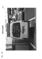
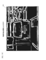
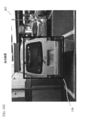
- FIG. 1 is a block diagram of an object detection system 10 according to a first embodiment. It is a figure which shows the color image 100A containing the object which has a symmetry. It is a figure which shows the luminance image 100B produced
- the figure which shows the input image 101 containing the object which has a symmetry The figure which shows the luminance image 102 produced
- FIG. The figure which shows the change (an example) of the horizontal direction of the symmetry evaluation map image 104.
- FIG. The figure for demonstrating the method to acquire symmetrical width wa.
- FIG. The figure which shows the feature-value extraction image (R component image (Cr component emphasis image)) 203.
- FIG. 1 The figure which shows the symmetrical width map image 205.
- FIG. The figure which shows the synthesized image (output image) 207 with which the area
- R component Feature quantity extraction image
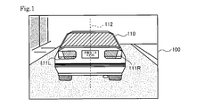
- FIG. 1 is a diagram illustrating a captured image 100 including a vehicle 110 as a subject.
- the vehicle 110 includes left and right tail lamps 111L and 111R.
- the left and right tail lamps 111L and 111R are arranged symmetrically with respect to the central axis 112 in the vehicle width direction of the vehicle 110.
- an object such as the vehicle 110 can be detected using the left-right symmetry included in the image.
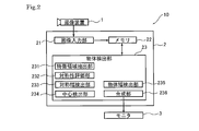
- FIG. 2 is a block diagram showing the object detection system 10 according to the first embodiment.
- the object detection system 10 includes an imaging device 1, an object detection device 2, and a monitor 3.
- the imaging device 1 includes an imaging element such as a CCD. An image captured by the imaging device 1 is input to the object detection device 2.
- the object detection device 2 is mounted on a vehicle.
- the imaging device 1 When the imaging device 1 is installed in the front part of the vehicle, the imaging device 1 captures an image in front of the vehicle.
- the imaging device 1 is equipped in the rear part of a vehicle, and images the back of a vehicle.
- the monitor 3 is installed in the driver's seat.
- the monitor 3 is also used as a monitor for a navigation system.
- the object detection device 2 includes an image input unit 21, a memory 22, and an object detection unit 23.
- the image input unit 21 inputs an image output from the imaging device 1. For example, when the imaging apparatus 1 is a CCD having RGB Bayer array color filters, the image input unit 21 inputs a pixel signal string including an R signal, a G signal, or a B signal. The image input unit 21 stores the input image in the memory 22.
- the object detection unit 23 performs image processing on the image stored in the memory 22 and detects an object having symmetry included in the image.
- the object detection unit 23 includes a feature region extraction unit 231, a symmetry evaluation unit 232, a symmetry width detection unit 233, a center detection unit 234, an object width detection unit 235, and a synthesis unit 236.
- the feature region extraction unit 231, the symmetry evaluation unit 232, the symmetry width detection unit 233, the center detection unit 234, the object width detection unit 235, and the synthesis unit 236 are configured by hardware circuits. However, all or part of these processing units may be realized by software processing. That is, each of these processing units may be configured by software and hardware such as a CPU and a memory that can execute the software.
- the image output from the object detection unit 23 is displayed on the monitor 3.
- a region frame indicating the region of the object is combined with the image displayed on the monitor 3. Thereby, the driver can easily recognize the object.
- FIG. 3A is a diagram illustrating a color image 100 ⁇ / b> A captured by the imaging apparatus 1.
- the color image 100A includes a vehicle 110.
- the vehicle 110 has tail lamps 111L and 111R attached to the rear of the vehicle.
- the image input unit 21 inputs the color image 100A and stores it in the memory 22. For example, if the imaging device 1 captures an image at 15 fps, the memory 22 stores a color image 100A of 15 fps.
- the color image 100A is, for example, an image in the RGB color space.
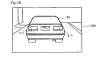
- the feature region extraction unit 231 acquires the color image 100A from the memory 22 and generates a luminance image 100B from the color image 100A.
- FIG. 3B is a diagram showing a luminance image 100B.
- the feature region extraction unit 231 performs YCbCr conversion on the color image 100A, extracts a Y signal image from the YCbCr color space image, and generates a luminance image 100B. .
- the luminance image 100B may be generated using a G signal in the RGB color space.
- a G signal may be generated by interpolation processing.
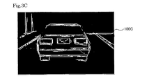
- the feature region extraction unit 231 performs edge detection processing on the luminance image 100B and generates an edge image 100C.
- FIG. 3C is a diagram showing an edge image 100C.
- the feature area extraction unit 231 generates an edge image 100C by performing a differentiation process on the luminance image 100B.
- the symmetry evaluation unit 232 evaluates the symmetry of the edge image 100C.
- a method for evaluating symmetry will be described.
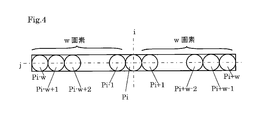
- Symmetry evaluation unit 232 evaluates the symmetry with respect to the target pixel P i shown in FIG.
- Target pixel P i is the pixel contained in the edge image 100C.
- the target pixel P i indicates a pixel at coordinates (i, j) in the edge image 100C.
- the notation of pixel P x indicates a pixel at coordinates (x, j) in the edge image 100C. That is, the notation of pixel P x indicates the pixel in the xth column in the horizontal direction and the pixel in the jth row in the vertical direction.
- P x denote the pixel value of the pixel P x. In the present embodiment, P x takes a value in the range of 0 to 255.
- SYM w (i, j) represents an evaluation value of symmetry.
- k is an integer that takes values from 1 to w.
- the pixel P i ⁇ k and the pixel P i + k are pixels that are located symmetrically about the target pixel P i .
- has a minimum value of 0.
- ) is the maximum value 255. That is, in (Expression 10), SYM w (i, j) takes a larger value as the symmetry is higher.
- SYM w (i, j) takes the maximum value 255.
- Symmetry evaluation unit 232 calculates the SYM w (i, j) for all w. Then, as shown in (Formula 11), the symmetry evaluation unit 232 calculates the maximum value maxSYM of SYM w (i, j) for the pixel of interest P i .
- N is the maximum value of w. Assuming that the number of pixels in the horizontal direction of the edge image 100C is H, N is (i ⁇ 1) when the column i indicating the horizontal position of the pixel of interest is (H / 2) or less. If the column i indicating the horizontal position of the pixel of interest is larger than (H / 2), N is (Hi).
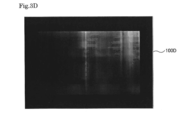
- the symmetry evaluation unit 232 performs the calculations of (Equation 10) and (Equation 11) for all the evaluation pixels to be evaluated for symmetry, and generates a symmetry map 100D shown in FIG. 3D.
- all the pixels of the edge image 100C are used as the evaluation pixels. That is, for all the pixels included in the edge image 100C, SYM w (i, j) is calculated and maxSYM is calculated.
- some pixels included in the edge image 100C may be used as evaluation pixels. For example, only odd lines or only even lines in the horizontal (or vertical) direction may be used as evaluation pixels. Alternatively, the number of evaluation pixels may be reduced by selecting evaluation pixels at intervals of three lines.
- the symmetry map 100D is a map having, as components, the value of maxSYM calculated for each evaluation pixel. Each evaluation pixel may be considered as an image having a pixel value of maxSYM calculated for the evaluation pixel.
- FIG. 3D depicts the symmetry map 100D as an image.
- the symmetry map 100D is a grayscale image in which the pixel values of all the pixels of the edge image 100C are replaced with maxSYM. .
- SYM w (i, j) can take a value of 0 to 255. Accordingly, each component of the symmetry map 100D can take a value of 0 to 255.
- a color close to white indicates that the value of SYM w (i, j) is large (close to 255). That is, in FIG. 3D, the whitish region is a region highly evaluated for symmetry, and indicates the vicinity of the center of the symmetric object.
- a dark area is an area where the symmetry is not high.
- the symmetry width detection unit 233 generates a symmetry width map 100E shown in FIG. 3E for all evaluation pixels for which symmetry is to be evaluated.
- the symmetrical width map 100E is a map having a symmetrical width wa that gives maxSYM for each evaluation pixel as a component. Each evaluation pixel may be considered as an image having a symmetric width wa as a pixel value.
- FIG. 3E depicts the symmetrical width map 100E as an image.
- the symmetry width map 100E is a grayscale image in which all the pixels of the edge image 100C are replaced with the symmetry width wa.
- the symmetry width wa can take a value from 1 to N. Therefore, each component of the symmetry width map 100E can take a value of 1 to N.
- the value of N varies depending on the pixel position. In FIG. 3E, a region where the color is close to white indicates a region where the symmetry width wa is large. In FIG. 3E, a region where the color is close to black indicates a region where the symmetry width wa is small.
- the center detection unit 234 refers to the symmetry map 100D and generates a symmetry center map 100F.
- the center detection unit 234 selects, as the symmetry center pixel, a pixel that gives a maximum point of maxSYM for each horizontal line of the symmetry map 100D.
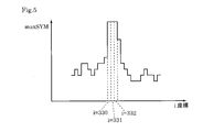
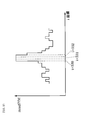
- FIG. 5 is a diagram showing a change in the horizontal direction of the symmetry map 100D.
- FIG. 5 is a diagram showing a change in maxSYM for one horizontal line of the symmetry map 100D.
- This figure shows an example in which the symmetry map 100D is a local maximum point in three coordinates 330, 331, and 332 in the column (i coordinate) indicating the horizontal position.
- the center detection unit 234 specifies coordinates that give maximum points for all the horizontal lines.
- FIG. 3F is a symmetry center map 100F in which the symmetry center pixels specified by the center detection unit 234 are plotted.
- the symmetry center map 100F it can be seen that the component “1” is given to the coordinates specified for the symmetry center pixel and the component “0” is given to the coordinates not specified for the symmetry center pixel.
- the white part shows the pixel specified as the symmetrical central pixel.
- the pixel value serving as the maximum point may be compared with a preset threshold value and specified as a symmetrical central pixel only when the threshold value is exceeded. As a result, it is possible to eliminate local maximum points caused by fine fluctuations.
- the object width detection unit 235 detects the horizontal width and the vertical width of the symmetrical object included in the edge image 100C.
- the object width detection unit 235 uses the symmetry center map 100F and the symmetry width map 100E as the horizontal width of the object.
- the pixel value “1” is given to the pixels constituting the center axis of the object having symmetry.
- the object width detection unit 235 extracts a pixel having a pixel value “1” in the symmetry center map 100F, and acquires the symmetry width of the extracted pixel from the symmetry width map 100E.
- the symmetry width is acquired for all the symmetry center pixels.
- the average value is set as the symmetrical width with respect to the horizontal line.
- the symmetric width is acquired for all horizontal lines, and the maximum width is detected as the object width.
- the maximum value may be the symmetrical width in the horizontal direction.
- the object width detection unit 235 may determine the symmetrical width for each horizontal line and then set the average value as the object width.
- the maximum value or average value of the symmetric width is set as the horizontal width of the object, the width of the object is represented by one value.
- the object width may be determined for each horizontal line.
- the object width detection unit 235 uses the vertical width of the symmetrical central pixel as the vertical width of the object. In other words, the object width detection unit 235 identifies the upper end of the symmetrical central pixels arranged continuously in the vertical direction as the upper end of the object, and uses the lower end of the symmetrical central pixels arranged continuously in the vertical direction as the lower end of the object. Identify.
- the synthesizing unit 236 generates a rectangular image indicating the horizontal width and the vertical width of the object specified by the object width detecting unit 235, and synthesizes the color image 100A.
- FIG. 3G shows a composite image 100G in which a region frame 130 indicating a region of the vehicle 110 that is an object having symmetry is combined with the color image 100A.
- the area frame is not a rectangle, but has a shape that follows the outer shape of the object.
- the feature region extraction unit 231 uses an edge component as a feature amount of an object. Then, the symmetry was evaluated based on the edge component extracted as the feature amount.
- the feature region extraction unit 231 uses a specific color component as the feature amount of the object. For example, the feature region extraction unit 231 extracts a red component as a feature amount. For example, the feature region extraction unit 231 converts an image in the RGB color space stored in the memory 22 into an image in the YCbCr color space. The feature region extraction unit 231 extracts a Cr component from the image in the YCbCr color space, and generates a Cr image. The feature region extraction unit 231 further performs a red component enhancement process on the Cr image to generate an R component image.
- the subsequent processing is the same as in the first embodiment. After replacing the edge image in the first embodiment with the R component image, the same processing is executed to detect a symmetrical object.
- the same processing is executed to detect the position and size of an object at the same time by using a specific color component of the image and using the symmetry of the object included in the image.
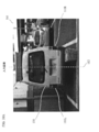
- FIG. 6 is a diagram showing a composite image 100G displayed on the monitor 3 in the second embodiment.
- the entire vehicle is extracted as the size of the object.
- the second embodiment since the symmetry of the object is evaluated around the red color of the tail lamp, it can be seen that a region including the tail lamp is extracted.
- Both the first embodiment and the second embodiment may be combined.
- the vertical and horizontal widths and positions of the object are specified with respect to the edge image. Further, the vertical and horizontal widths and positions of the object are specified using a specific color component image.
- the position and size of the object can be specified by taking the average value. Alternatively, the position and size of the object may be specified by weighting either the value obtained based on the edge image or the value obtained based on the color component.
- an object having symmetry with respect to the horizontal direction is detected.
- an object having symmetry with respect to the vertical direction may be detected. That is, an object having symmetry with respect to the vertical direction may be detected by reversing the horizontal processing and the vertical processing in the first embodiment.
- an object having symmetry with respect to the horizontal direction is detected.
- an object having symmetry in both the horizontal direction and the vertical direction may be excluded from the detection target, and an object having symmetry only in the horizontal direction may be detected.
- the symmetry evaluation value shown in (Formula 10) is calculated in both the horizontal direction and the vertical direction.
- the calculated evaluation value in the horizontal direction is SYM w H (i, j)
- the evaluation value in the vertical direction is SYM w V (i, j).
- FIG. 7 is a block diagram showing an object detection system 1000 according to the fifth embodiment.
- the object detection system 1000 includes an imaging device 1, an object detection device 2 ⁇ / b> A, and a display device 3.
- An imaging apparatus 1 includes an optical system (not shown) that collects light from a subject, and an imaging element (for example, a CCD image) that acquires subject light collected by the optical system as an image signal (electrical signal) by photoelectric conversion. Sensor or CMOS image sensor) (not shown).
- the imaging device 1 outputs an image (image signal) captured by the imaging device to the object detection device 2A.
- the object detection device 2A receives an image signal output from the imaging device 1, detects a symmetric object included in an image formed by the input image signal, and displays an image (image) indicating the detection result. Signal) to the display device 3.
- the object detection device 2A is mounted on a vehicle.
- the imaging device 1 When the imaging device 1 is installed in the front part of the vehicle, the imaging device 1 captures an image (scene) in front of the vehicle.
- the imaging device 1 is equipped in the rear part of a vehicle, and images the image (scene) of the back of a vehicle.
- the display device (monitor) 3 is equipped, for example, in the driver's seat of the vehicle.
- the display device 3 may also be used as a monitor for the navigation system.
- the object detection device 2A includes an image input unit 21A, an object detection unit 22A, and a synthesis unit 23A.
- the image input unit 21A inputs an image (image signal) output from the imaging device 1.
- the image input unit 21A includes, for example, a pixel signal including an R component signal, a G component signal, and a B component signal.
- a column is entered.
- the image input unit 21A converts the input image signal into a predetermined format as necessary, and outputs the converted image signal (an unconverted image signal if not converted) to the object detection unit 22A.
- the image input unit 21A outputs the input image signal to the synthesis unit 23A.
- the “conversion to a predetermined format” is, for example, color space conversion (for example, conversion from the RGB color space to the YCbCr color space).
- the image input unit 21A converts the input RGB color space image signals (R component signal, G component signal, and B component signal), for example, as required, for example, in a YCbCr color space signal (Y component signal, Cb component signal). And Cr component signal).
- an input RGB color space image signal (R component signal, G component signal and B component signal) is converted into a YCbCr color space signal (Y component signal, A case where the signals are converted into (Cb component signal and Cr component signal) will be described as an example.
- the object detection unit 22A receives an image (image signal) output from the image input unit 21A, performs predetermined image processing on the input image, and executes an image (an image (for example, an image formed by the image signal (for example, Frame image)) is detected (the image area corresponding to the object having symmetry is specified). Then, the object detection unit 22A outputs a detection result (for example, information for specifying an image region corresponding to an object having symmetry) to the synthesis unit 23A.
- an image for example, an image formed by the image signal (for example, Frame image)
- a detection result for example, information for specifying an image region corresponding to an object having symmetry
- the object detection unit 22A includes an image feature amount extraction unit 221, a symmetry evaluation unit 222, a center detection unit 223, and an object region detection unit 224, as shown in FIG.
- the image feature quantity extraction unit 221 calculates (extracts) an image feature quantity from the image output from the image input unit 21A. Specifically, the image feature quantity extraction unit 221 uses, for example, a Sobel filter from a Y component image (luminance component image) formed by a Y component signal (luminance component signal) output from the image input unit 21A. The edge component is extracted as an image feature amount by the differential operation processing. Then, the image feature quantity extraction unit 221 outputs an image (feature quantity extraction image) having the extracted edge component as the pixel value of each pixel as an image feature quantity extraction image to the symmetry evaluation unit 222 and the object region detection unit 224. To do.
- a Sobel filter from a Y component image (luminance component image) formed by a Y component signal (luminance component signal) output from the image input unit 21A.
- the edge component is extracted as an image feature amount by the differential operation processing.
- the image feature quantity extraction unit 221 outputs an image (feature quantity extraction image) having the extracted edge component as
- the symmetry evaluation unit 222 receives the image (feature amount extraction image) extracted by the image feature amount extraction unit 221 as an input. Then, the symmetry evaluation unit 222 evaluates (determines) symmetry in a predetermined direction (for example, the horizontal direction) on the image for each pixel from the feature amount extraction image and the width of the image region having high symmetry. (Width of the predetermined direction (for example, horizontal direction)) is determined (estimated). Then, for each pixel, the symmetry evaluating unit 222 specifies information (for example, pixel coordinates) for specifying the pixel (processing target pixel) and a value indicating the degree of symmetry evaluated (determined) (or the value). Symmetry evaluation map data in which a correlation value is associated with each other is acquired.
- a predetermined direction for example, the horizontal direction
- the symmetry evaluation unit 222 specifies information (for example, pixel coordinates) for specifying the pixel (processing target pixel) and a value indicating the degree of symmetry evaluated
- the symmetry evaluation unit 222 specifies information (for example, pixel coordinates) for specifying the pixel (processing target pixel), and the width of the determined (estimated) image area with high symmetry (the predetermined predetermined value). Symmetric width map data in which a value indicating a direction (for example, a width in the horizontal direction) (or a value correlated with the value) is associated is acquired.
- the symmetry evaluation unit 222 outputs the acquired symmetry evaluation map data to the center detection unit 223. Further, the symmetry evaluation unit 222 outputs the acquired symmetry width map data to the object region detection unit 224.
- the center detection unit 223 receives the symmetry evaluation map data acquired by the symmetry evaluation unit 222 as an input.
- the center detection unit 223 uses the symmetry evaluation map data as a two-dimensional image (an image generated by mapping the symmetry evaluation value as the pixel value of each pixel), a predetermined direction (for example, a horizontal direction) on the image.
- a pixel or a pixel region that takes a local maximum value (or a value near the local maximum value) is identified, and the position of the central axis of the highly symmetric object is determined (estimated) based on the identified pixel or pixel region.
- the center detection unit 223 outputs information related to the position (on the image) of the center axis of the determined (estimated) highly symmetric object to the object region detection unit 224.
- the object region detection unit 224 includes the symmetry width map data acquired by the symmetry evaluation unit 222 and information regarding the position (on the image) of the center axis of the highly symmetric object output from the center detection unit 223. As input.
- the object region detection unit 224 detects a highly symmetric object based on the symmetry width map data and information on the position (on the image) of the center axis of the highly symmetric object, and detects the detected symmetry. Identify areas on high object images. Then, the object area detection unit 224 outputs information about the area on the image of the specified object with high symmetry to the synthesis unit 23A.
- the synthesizing unit 23A inputs the image output from the image input unit 21A and the information specifying the region on the image of the detected highly symmetric object output from the object region detection unit 224 of the object detection unit 22A. And
- the combining unit 23A has a high symmetry on the image output from the image input unit 21A based on the information specifying the region on the image of the detected highly symmetrical object output from the object region detection unit 224.
- An image that clearly shows an image area corresponding to the object is generated (synthesized).
- the combining unit 23A generates (synthesizes) an image such that a square frame that clearly indicates an image region corresponding to an object with high symmetry is displayed on the image output from the image input unit 21A. Then, the combining unit 23A outputs the combined image to the display device 3.
- the display device 3 receives an image output from the synthesis unit 23A of the object detection device 2 and displays the image.
- FIG. 9 is a diagram illustrating an example of an image acquired at each stage of the object detection process executed in the object detection system 1000.
- FIG. 10A is a diagram illustrating a captured image 101 captured by the imaging device 1 and input to the object detection device 2.
- the captured image 101 includes a vehicle 110 as a subject, as shown in FIG. 10A.
- the vehicle 110 includes left and right tail lamps 111L and 111R.
- the left and right tail lamps 111L and 111R are arranged symmetrically with respect to the central axis 112 in the vehicle width direction of the vehicle 110.
- the captured image 101 illustrated in FIG. 10A is acquired in the imaging device 1 and the captured image 101 is processed by the object detection device 2 will be described as an example.
- the captured image 101 acquired by the imaging device 1 (image signal forming the captured image 101) is input to the image input unit 21A of the object detection device 2.
- the captured image 101 is an image formed by an R component signal, a G component signal, and a B component signal.
- the image input unit 21A performs a color space conversion process on the input captured image. Specifically, the image input unit 21A performs a process of converting the RGB color space into, for example, a YCbCr color space, and forms the captured image 101 with the R component signal, the G component signal, and the B component signal as the Y component. Signal, Cb component signal, and Cr component signal are converted.
- the image input unit 21A outputs a Y image (luminance image) formed by the Y component signal (luminance signal) to the image feature amount extraction unit 221 of the object detection unit 22A.
- the image input unit 21 outputs the input captured image to the synthesis unit 23A.
- FIG. 10B shows a Y image (luminance image) 102 acquired by the image input unit 21A.
- the color space conversion process in the image input unit 21A is not limited to the above.
- the RGB color space is converted into another color space such as a Lab color space or a YPbPr color space. May be.
- the luminance image 102 may be generated using a G signal in the RGB color space.
- a G signal may be generated by interpolation processing.
- the color space processing may be executed using a memory (not shown) that can store an image signal such as a frame memory.
- the image feature amount extraction unit 221 executes processing for calculating (extracting) an image feature amount with respect to the Y image (luminance image) 102 acquired by the image input unit 21A.
- a physical quantity correlated with the edge component of luminance is used as the image feature quantity.
- the image feature quantity extraction unit 221 performs edge detection processing on the luminance image 102 and generates a feature quantity extraction image (edge image) 103.
- FIG. 10C is a diagram illustrating a feature amount extraction image (edge image) 103 acquired by the image feature amount extraction unit 221.
- the image feature amount extraction unit 221 generates a feature amount extraction image (edge image) 103 by performing, for example, differentiation processing (for example, filter processing using a Sobel filter) on the luminance image 102.
- differentiation processing for example, filter processing using a Sobel filter
- the symmetry evaluation unit 222 evaluates the symmetry of the edge image 103 acquired by the image feature amount extraction unit 221.
- a method for evaluating symmetry will be described.
- Symmetry evaluation unit 222 evaluates the symmetry with respect to the target pixel P i shown in FIG. 11.
- the pixel of interest P i is a pixel included in the edge image 103.
- a target pixel P i indicates a pixel at coordinates (i, j) in the edge image 103.
- the notation of pixel P x indicates a pixel at coordinates (x, j) in the edge image 103. That is, the notation of pixel P x indicates the pixel in the xth column in the horizontal direction and the pixel in the jth row in the vertical direction.
- P x denote the pixel value of the pixel P x.
- P x takes a value in the range of 0 to 255. Note that P x takes a larger value as the image feature amount (edge component amount in the present embodiment) is larger (as the degree of the image feature amount of interest is stronger).
- FIG. 11 shows w pixels (P i-w to P i-1 ) located on the left side of the pixel of interest P i of the pixel, and w pixels (w is a natural number) located on the right side of the pixel of interest P i.
- Pixels (P i + 1 to P i + w ) are drawn.
- An arithmetic expression for evaluating the symmetry of the 2w + 1 pixels (P i ⁇ w to P i + w ) is shown below (Formula 14).
- SYM w (i, j) represents a symmetry evaluation value (symmetry evaluation value).
- k is an integer taking a value from 1 to w.
- Th is a predetermined threshold value.
- the function f i (k) is (1) When P i ⁇ k > Th or P i + k > Th,
- (2) In other cases (that is, when P i ⁇ k ⁇ Th and P i + k ⁇ Th), “255” (the maximum value that P x can take). Therefore, SYM w (i, j) is “0” when P i ⁇ k and P i + k are both equal to or less than the threshold Th (since 255 ⁇ f i (k) 0).
- a pixel having a small image feature amount (a pixel having a small pixel value (corresponding to an image feature amount) in the feature amount extracted image (edge image) 103) is excluded from the symmetry evaluation target. Will be.
- the pixel P i ⁇ k and the pixel P i + k are pixels that are located symmetrically about the target pixel P i .
- becomes the minimum value 0.
- f i (k) 0. Therefore, (255 ⁇ f i (k)) is the maximum value 255.
- (255 ⁇ f i (k)) is a distance k from the target pixel (i, j) (from the target pixel (i, j) to the pixel (i, j + k) (or pixel (i, j ⁇ k)).
- weighting is performed with horizontal position information (distance information from the target pixel). That is, as the distance from the target pixel in the horizontal direction is increased, the weighting for the symmetry evaluation is increased. Therefore, there is a region having high (left / right) symmetry (symmetry with respect to the image feature amount of interest (edge component amount in this embodiment)) in a region left and right from the pixel of interest with the pixel of interest at the center.
- the symmetry evaluation value SYM w (i, j) is a large value.
- Symmetry evaluation unit 222 with respect to the pixel of interest P i, by changing the w, w to calculate the SYM w (i, j) for. Then, the symmetry evaluation unit 222 calculates the maximum value maxSYM of SYM w (i, j) for the pixel of interest P i as shown in the following (Formula 15).
- N is the maximum value of w. Assuming that the number of pixels in the horizontal direction of the edge image 103 is H, N is (i ⁇ 1) when the column i indicating the horizontal position of the pixel of interest is (H / 2) or less. If the column i indicating the horizontal position of the pixel of interest is larger than (H / 2), N is (Hi).
- max () is a function for obtaining the maximum value of the element. That is, according to (Equation 15), maxSYM contains the maximum value of SYM 1 (i, j) to SYM N (i, j).
- FIGS. 12A to 12F show examples of feature amount extraction images, and are diagrams schematically showing feature amount extraction images of images obtained by imaging a bilaterally symmetric object with the axis C1 as a symmetry axis. is there.
- FIGS. 12A to 12F show examples of feature amount extraction images, and are diagrams schematically showing feature amount extraction images of images obtained by imaging a bilaterally symmetric object with the axis C1 as a symmetry axis. is there. In FIGS.
- a region R1 indicates a region that is calculated symmetrically according to (Equation 14).
- the image feature amount (pixel value) P x of the pixel included in the white portion is “255”, and the image of the pixel included in the other black portion is displayed. It is assumed that the feature amount P x is “0”.
- w the value of w is as follows.
- w (w in FIG. 12D) is wa.
- the symmetry evaluation unit 222 performs processing corresponding to (Equation 14) and (Equation 15) for all the pixels for which symmetry is to be evaluated, (1) Symmetry evaluation map data associating a processing target pixel with a value of maxSYM corresponding to the pixel (or a value correlated with the value of maxSYM); (2) Symmetric width map data in which a processing target pixel is associated with a value of wa (a value of w when taking the maximum value maxSYM) (or a value correlated with the value of wa); Is generated (obtained).
- FIG. 10D is a symmetry evaluation map image 104 derived from the symmetry evaluation map data.
- the symmetry evaluation map image 104 is an image in which the pixel value of each pixel is a corresponding value of maxSYM (or a value correlated with the value of maxSYM).
- FIG. 10E shows a symmetric width map image 105 derived from the symmetric width map data.
- the symmetrical width map image 105 is an image in which the pixel value of each pixel is the corresponding wa value (the value of w when taking the maximum value maxSYM) (or a value correlated with the value of wa).
- the symmetry evaluation unit 222 uses all the pixels of the edge image 103 as target pixels (evaluation pixels) for evaluating symmetry. That is, for all the pixels included in the edge image 103, the symmetry evaluation unit 222 calculates SYM w (i, j) and calculates maxSYM.
- the symmetry evaluation unit 222 uses a part of pixels included in the edge image 103 (thinning out pixels) and performs the same processing as described above.
- symmetry evaluation map data and symmetry width map data may be acquired.
- the symmetry evaluation unit 222 may use only odd lines or only even lines in the horizontal (or vertical) direction as pixels (evaluation pixels) to be evaluated for symmetry.
- the number of evaluation pixels may be reduced by selecting evaluation pixels at intervals of three lines.
- the symmetry evaluation map data is map data having, as components, the value of maxSYM (or a value correlated with the value of maxSYM) calculated for each evaluation pixel.
- Each evaluation pixel may be considered as an image having a pixel value of the value of maxSYM (or a value correlated with the value of maxSYM) calculated for the evaluation pixel.
- FIG. 10D depicts the symmetry evaluation map data as an image (symmetry evaluation map image 104). Note that the symmetry evaluation unit 222 only needs to acquire the value of maxSYM (or a value correlated with the value of maxSYM) calculated for each evaluation pixel, and the image (symmetry evaluation) shown in FIG. The map image 104) may not be acquired. That is, the symmetry evaluation unit 222 only needs to acquire data in which each evaluation pixel is associated with the value of maxSYM.
- the symmetry evaluation map image 104 sets the pixel values of all the pixels of the edge image 103 to the value of maxSYM (or the value of maxSYM). Is a grayscale image replaced with a value correlated with
- the symmetry evaluation value SYM w (i, j) is data in which the range that can be taken varies depending on the value of w when calculated by the above (Formula 14), and the symmetry having the value of maxSYM as it is as the pixel value.
- the evaluation map image 104 may be acquired, for example, dynamic range conversion may be performed and the symmetry evaluation map image 104 may be acquired. That is, for example, the range determined by the minimum value to the maximum value of maxSYM calculated for an input image for one frame is, for example, a range of 0 to 255 (8-bit range). Dynamic range adjustment may be performed (or normalization processing, processing corresponding to clip processing at a predetermined value, gain adjustment processing, or the like may be performed).
- each component of the symmetry evaluation map image 104 can take a value of 0 to 255, respectively.
- a color close to white indicates that the value of SYM w (i, j) is large (close to 255). That is, in FIG. 10D, the whitish region is a region highly evaluated for symmetry, and shows the vicinity of the center of the symmetric object. On the other hand, in FIG. 10D, a dark area is an area where the symmetry is not high. Note that the dynamic range conversion is an example, and SYM w (i, j) may be converted into a range other than the range of 0 to 255.
- the symmetry evaluation unit 222 generates (acquires) symmetry width map data for all evaluation pixels for which symmetry is to be evaluated.
- Symmetric width map data is map data having a symmetrical width wa giving maxSYM for each evaluation pixel as a component. Each evaluation pixel may be considered as an image having a symmetric width wa as a pixel value.
- the symmetrical width map data is drawn as an image (symmetric width map image 105).
- the symmetrical width map image 105 is a grayscale image in which all the pixels of the edge image 103 are replaced with the symmetrical width wa.
- the symmetry width wa can take a value from 1 to N. Therefore, each component of the symmetrical width map image 105 can take a value of 1 to N.
- the value of N varies depending on the pixel position.
- a region where the color is close to white indicates a region where the symmetry width wa is large.
- an area where the color is close to black indicates an area where the symmetry width wa is small.
- the center detection unit 223 refers to the symmetry evaluation map data (symmetry evaluation map image 104) generated by the symmetry evaluation unit 222, and generates symmetry center map data (symmetry center map image 106).
- the center detection unit 223 determines (estimates) a pixel (or a pixel group near the maximum point) that provides a maximum point of maxSYM for each horizontal line of the symmetry evaluation map image 104.
- FIG. 13 is a diagram showing a change in the horizontal direction of the symmetry evaluation map image 104. Specifically, FIG. 13 is a diagram illustrating a change in maxSYM for one horizontal line of the symmetry evaluation map image 104.
- the center detection unit 223 specifies (estimates) a region (pixel or pixel group) that gives a maximum point (region near the maximum point) for all the horizontal lines.
- the area specified (estimated) by the center detection unit 223 is referred to as a “symmetric center pixel area”.
- FIG. 10F is a symmetric center map image 106 that clearly shows the symmetric center pixel area specified (estimated) by the center detection unit 223.
- a component (pixel value) “1” is set to a pixel determined to be included in the symmetric center pixel area, and a pixel determined not to be included in the symmetric center pixel area is set to It can be seen as an image acquired by setting the component (pixel value) “0”.
- the white portion indicates the pixel specified as the symmetrical central pixel region.
- the determination as to whether or not the processing target pixel (target pixel) is included in the symmetric central pixel region may be performed together with the following processing, for example.
- smoothing process smoothing process on the horizontal line to be processed
- the object region detection unit 224 detects the horizontal width and the vertical width of the symmetrical object included in the input image.
- the object region detection unit 224 detects the horizontal width of the object using the symmetric center map data (symmetric center map image 106) and the symmetric width map data (symmetric width map image 105).
- the object region detection unit 224 detects the horizontal width of the object by, for example, the following processes (1) to (5).
- the horizontal line including the pixel having the pixel value “1” is first assumed to be the j-th line.
- the pixel value “1” is given to the pixels constituting the center axis of the object having symmetry. Therefore, the object region detection unit 224 extracts a pixel having a pixel value “1” in the symmetric center map image 106 and acquires the symmetric width of the extracted pixel from the symmetric width map image 105.
- AVRG () is a function that takes an average value of elements
- MAX () is a function that takes a maximum value of elements.
- W (i, j) calculated by the above (1A) or (1B) in the j-th horizontal line is denoted as W (i0, j).
- A is a predetermined threshold (a value for determining whether or not the horizontal direction is substantially equal)), and if there is a pixel whose pixel value is “1”, Similar to 1), the symmetric width of the pixel is extracted from the symmetric width map data.
- the object region detection unit 224 calculates the symmetric width W (i1, j) of the pixel (i 1 , j + 1) in the same manner as the processing (1).
- the same processing as above is repeated for the horizontal lines after the j + 2th row.
- the pixel extracted in the above (1) is substantially equal in position in the horizontal direction (for example, a pixel included in the range of the coordinate position (ia, j + 1) to the coordinate position (i + a, j + 1), where The above process is repeated until no pixel having the pixel value “1” appears in the threshold value (value for determining whether or not the horizontal directions are substantially equal).
- the object region detection unit 224 obtains the maximum value maxW of the symmetry width calculated by the processes (1) to (3). That is, the object region detection unit 224 obtains the maximum value maxW of the symmetry width by executing a process corresponding to the following (Equation 16).
- the pixel extracted in the above (1) and the position in the horizontal direction are substantially equal (for example, pixels included in the range of the coordinate position (i ⁇ a, j + 1) to the coordinate position (i + a, j + 1)).
- A is a horizontal line in which a pixel having a pixel value “1” appears within a predetermined threshold value (a value for determining whether or not the horizontal directions are substantially equal) from the j-th line to the j + m ⁇ 1-th line. It is going to be.
- the object region detection unit 224 detects the calculated maximum value maxW of the symmetric width as the object width (the distance from the center of the object in the horizontal direction to one end).
- the object area detection unit 224 detects the vertical width of the object using the vertical width (length) of the symmetric central pixel area. That is, the object region detection unit 224 specifies the upper end of the symmetrical central pixel arranged continuously in the vertical direction as the upper end of the object, and uses the lower end of the symmetrical central pixel arranged continuously in the vertical direction as the lower end of the object. Identify.
- the object region detection unit 224 has the upper ends of the symmetrical central pixels arranged continuously in the vertical direction at the horizontal line position of the j-th row and arranged continuously in the vertical direction.
- the object area detection unit 224 synthesizes information indicating the image area of the specified object (object having high symmetry) (for example, information for specifying the area R1 (for example, coordinate information of the rectangular area)). To the unit 23A.
- the object region detection unit 224 has described a case in which an image region of a highly symmetric object is specified by a rectangular region, but is not limited thereto.
- the object region detection unit 224 may specify an image region of a highly symmetric object for each horizontal line based on the symmetry width extracted from the symmetry width map data.
- a region having a length corresponding to the symmetric width from the symmetric central pixel (the pixel included in the symmetric central pixel region) to the left and right is specified as the image region of the highly symmetric object.
- the image area of the object with high symmetry finally detected has a shape that substantially matches the shape of the object with high symmetry (for example, substantially matches the shape of the outer frame of the vehicle 110 in FIG. 10A). Will be in the form).
- the combining unit 23A Based on the information specifying the region on the image of the detected object with high symmetry that is output from the object region detection unit 224, the combining unit 23A is placed on the image (input image 101) output from the image input unit 21A. Then, an image that clearly shows an image area corresponding to an object with high symmetry is generated (synthesized). For example, the combining unit 23A generates (synthesizes) an image such that a square frame that clearly indicates an image region corresponding to an object with high symmetry is displayed on the image output from the image input unit 21A. Then, the combining unit 23A outputs the combined image to the display device 3.
- the display device 3 displays an image in which an image region corresponding to a highly symmetric object is output, which is output from the combining unit 23A of the object detection device 2.
- FIG. 9G shows a composite image 107 in which an area frame 130 indicating an area of the vehicle 110 that is an object having symmetry is combined with the input image 101.
- the area frame is not rectangular but has a shape that conforms to the outer shape of the object (a shape that substantially matches the shape of the outer frame of the vehicle 110).
- the object detection system 1000 in order to evaluate symmetry in a predetermined direction (horizontal direction) with respect to an image obtained by extracting image feature amounts of an input image (captured image), The symmetry is evaluated while changing the width (the width in the predetermined direction (horizontal direction)). Therefore, in the object detection system 1000 according to the present embodiment, when it is determined that the predetermined image area has high symmetry, the width in the predetermined direction (horizontal direction) of the image area determined to have high symmetry can be acquired at the same time. it can. That is, in the object detection system 1000 of the present embodiment, it is possible to simultaneously extract the position and size of an object using the symmetry of the object included in the image.
- the object detection system 1000 can detect the central axis of an object with high symmetry using the evaluation data for symmetry in a predetermined direction (horizontal direction). Therefore, the object detection system 1000 of the present embodiment can detect an object with high symmetry and high accuracy with a small amount of calculation.
- a symmetry evaluation value that is weighted according to the distance from the pixel of interest (center axis (symmetric axis) of the object) is acquired, and processing using the symmetry evaluation value is performed. Since this is performed, it is possible to accurately detect a highly symmetric object existing at a position away from the central axis (symmetric axis).
- the object detection system and the object detection device of this modification have the same configurations as the object detection system 1000 and the object detection device 2 of the first embodiment.
- the symmetry evaluation unit 222 performs processing according to the following (Equation 17) or (Equation 18) instead of the above (Equation 14). Other than that, this modification is the same as the fifth embodiment.
- the symmetry evaluation unit 222 performs the processing according to the above (Equation 17) on the feature amount extracted image (edge image) 103.
- weighting is performed by (w ⁇ k). That is, on the feature amount extraction image (edge image) 103, the region that is located closer to the target pixel is weighted more strongly.
- the symmetry evaluation value SYM w (i, j) is a large value in a region close to the target pixel and having high left-right symmetry.
- the symmetry evaluation unit 222 may perform processing according to the following (Equation 18) on the feature amount extraction image (edge image) 103.
- Weighting is performed by a function c (k) that monotonously decreases in a section of k ⁇ a0 (a0 is a predetermined value that satisfies a0 ⁇ w). That is, on the feature amount extraction image (edge image) 103, the region that is located closer to the target pixel is weighted more strongly.
- the symmetry evaluation value SYM w (i, j) is a large value in a region close to the target pixel and having high left-right symmetry.
- FIG. 14 is a diagram schematically illustrating an example of a feature amount extraction image. Pixels included in a white part region have maximum values (for example, “255” (8 Bit data)), and a pixel included in a black portion is a minimum value (for example, “0” (8-bit data)) that the pixel value (image feature amount) can take. Further, the value a0 in (Equation 18) is slightly larger than w1 (shown in FIG. 14) as shown in FIG.
- the symmetry evaluation value SYM w (i, j) is obtained when the horizontal width w1 of the region R2 is set.
- the evaluation value SYM w (i, j) is the symmetric width w) when the maximum value is obtained.
- the weighting c (k) for the region where w is greater than a0 is monotonously decreased with respect to w.
- the value of the weighting c (k) for BR is a small value. Therefore, when the horizontal width of the region R2 is w2, the symmetry evaluation value SYM w (i, j) is smaller than the symmetry evaluation value SYM w (i, j) when the horizontal width w1. It becomes.
- the symmetry evaluation unit 222 of the object detection system performs processing corresponding to (Expression 18) to acquire the symmetry evaluation value SYM w (i, j) and the symmetry evaluation value.
- the symmetry width wa when SYM w (i, j) is maximized is acquired.
- the maximum w is assumed to be wa. It may be.
- the symmetry width when the value of w is the maximum is the symmetry axis. It is highly possible that the value is close to the width of a highly symmetric object existing in the vicinity.
- the center detection unit 223 and the object region detection unit 224 perform processing similar to that of the fifth embodiment, so that an object (region) having high left-right symmetry can be appropriately detected in the vicinity of the symmetry axis.
- the object detection system of this modification example appropriately detects an object (region) BC with high left-right symmetry in the vicinity of the symmetry axis as the detection region DA1. be able to.
- weighting function c (k) based on the distance on the image is not limited to the function shown in (Formula 18), and may be set to an arbitrary function.
- the weighting function c (k) according to the distance on the image is changed to a monotone decreasing function (when there is a section where c (k) has a constant value for some k, as shown in FIGS. 16A and 16B, etc. May be included).
- a monotone decreasing function when the weighting function c (k) is set to a monotone decreasing function, an object having high symmetry near the symmetry axis can be detected.
- FIG. 16A corresponds to the processing of (Formula 18) of this modification.
- the weighting function c (k) according to the distance on the image is a monotonically increasing function (when there is a section where c (k) has a constant value for some k, etc. May be included).
- the weighting function c (k) is set to a monotonically increasing function, an object having high symmetry can be detected in a region away from the symmetry axis.
- the weighting function c (k) based on the distance on the image is not limited to the above.
- the weighting function c (k) based on the distance on the image by a function using an exponential function, a sigmoid function, or the like A function c (k) may be set.
- the weighting function c (k) according to the distance on the image is set to a monotone decreasing function (which may include a part that is not monotonous), so that the vicinity of the symmetry axis It is possible to appropriately detect an object having high symmetry.
- the configuration of the object detection system of this embodiment is the same as that of the fifth embodiment.
- differences of the present embodiment from the fifth embodiment will be described.
- symbol is attached
- the image feature amount extraction unit 221 uses an edge component as an image feature amount of an object. Then, the symmetry was evaluated based on the edge component extracted as the image feature amount.
- the image feature amount extraction unit 221 uses a specific color component as the image feature amount of the object. For example, the image feature amount extraction unit 221 extracts a red component as the image feature amount.
- FIG. 17A is a diagram illustrating an example of an image acquired at each stage of the object detection process executed in the object detection system of the present embodiment.
- the image input unit 21A converts an RGB color space image signal (R component signal, G component signal, and B component signal) input from the imaging apparatus 1 into a YCbCr color space signal (Y component signal, Cb component signal, and Cr component). Signal). Then, the image input unit 21 ⁇ / b> A outputs a Cr component signal (Cr component image 202) to the image feature amount extraction unit 221.
- the image feature amount extraction unit 221 executes a process of extracting an image feature amount with respect to the Cr component image (color difference red component image) 202 acquired by the image input unit 21A.
- a physical quantity having a correlation with the Cr component is used as the image feature quantity.
- the image feature quantity extraction unit 221 performs Cr component enhancement processing (enhancement processing) on the Cr component image 202, and a feature quantity extraction image (R component image (Cr component enhancement image)) 203. Is generated.
- the subsequent processing is the same as in the fifth embodiment. After replacing the edge image in the fifth embodiment with the R component image, the same processing is executed to detect a symmetrical object.
- the symmetry evaluation unit 222 performs the same processing as that of the fifth embodiment on the feature amount extraction image (R component image (Cr component enhanced image)) 203 illustrated in FIG. (Corresponding to the symmetry evaluation map image 204 shown in FIG. 17D) and symmetry width map data (corresponding to the symmetry width map image 205 shown in FIG. 17E) are acquired.
- the center detection unit 223 performs the same processing as that of the fifth embodiment on the symmetry evaluation map data (corresponding to the symmetry evaluation map image 204 shown in FIG. 17D), and the symmetry center map data (FIG. Corresponding to the symmetrical center map image 206 shown in FIG. 17F).
- the object region detection unit 224 performs the same processing as that of the fifth embodiment by using the symmetry center map data (corresponding to the symmetry center map image 206 shown in FIG. 17F) and the symmetry width map data (symmetric width map image 205). Then, the horizontal width of the object is detected, and further the vertical width of the object is detected.
- the synthesizing unit 23A is output from the image input unit 21A based on the information that is output from the object region detection unit 224 and that specifies the region on the image of the detected object with high symmetry. On the image (input image 101), an image that clearly shows an image region corresponding to an object with high symmetry is generated (synthesized).
- FIG. 17G shows an example of an image (output image 207) acquired by the synthesis unit 23A. As shown in FIG. 17G, a region having a red image region (image region 230) at a symmetrical position is appropriately detected.
- FIG. 17G is a diagram showing the composite image 207 displayed on the display device 3 in the sixth embodiment.
- the entire vehicle is extracted as the size of the object.
- the sixth embodiment since the symmetry of the object is evaluated around the red color of the tail lamp of the vehicle, it can be seen that the area (image area 230) including the tail lamp is extracted.
- a predetermined direction (horizontal direction) with respect to an image an image obtained by extracting a specific color component
- the symmetry is evaluated while changing the width (the width in the predetermined direction (horizontal direction)). Therefore, in the object detection system of the present embodiment, when it is determined that the predetermined image area has high symmetry, the width in the predetermined direction (horizontal direction) of the image area determined to have high symmetry can be acquired at the same time. . That is, in the object detection system of the present embodiment, it is possible to extract the position and size of an object at the same time using the symmetry of the object included in the image.
- the object detection system of the present embodiment it is possible to detect the central axis of a highly symmetric object using the symmetry evaluation data in a predetermined direction (horizontal direction). Therefore, the object detection system of the present embodiment can detect an object with high symmetry and high accuracy with a small amount of calculation. Furthermore, in the object detection system of the present embodiment, processing is performed using an image extracted for a specific color component, so that a highly symmetric object including a large amount of the specific color component can be detected with high accuracy.
- a symmetry evaluation value weighted by a distance from the pixel of interest (center axis (symmetric axis) of the object) is acquired, and processing using the symmetry evaluation value is performed. Therefore, it is possible to accurately detect an object having high symmetry with respect to a specific color component that exists at a position away from the central axis (symmetry axis).
- the vertical and horizontal widths and positions of the object are specified with respect to the edge image. Further, the vertical and horizontal widths and positions of the object are specified using a specific color component image.
- the position and size of the object can be specified by taking the average value. Alternatively, the position and size of the object may be specified by weighting either the value obtained based on the edge image or the value obtained based on the color component.
- processing is performed while paying attention to the red component.
- the present invention is not limited to this, and processing is performed while paying attention to other color components (for example, the green component and the blue component). You may make it detect the object with high symmetry about a predetermined color.
- the color space conversion for extracting the image feature amount is not limited to that described in the present embodiment, and other color space conversion is performed in order to extract a signal of a specific color component, A desired color component signal (color component image) may be extracted.
- the object detection system and the object detection device of this modification have the same configuration as the object detection system and the object detection device of the fifth embodiment, respectively.
- the symmetry evaluation unit 222 performs processing according to (Expression 17) or (Expression 18) instead of (Expression 14), as in the modification of the fifth embodiment.
- the image feature quantity extraction unit 221 uses a specific color component as the image feature quantity of the object, as in the sixth embodiment. For example, the image feature amount extraction unit 221 extracts a red component as the image feature amount.
- FIG. 18A shows an image 301 obtained by imaging a motorcycle from behind.
- the motorcycle tail lamp 311 is assumed to be red.
- the image feature quantity extraction unit 221 of the object detection unit 22A performs the feature quantity extraction image (R component (R component (2)) shown in FIG. Cr component) extracted image) 302 is acquired.
- the feature amount extraction image (R component (Cr component) extraction image) 302 shown in FIG. 18B a region corresponding to the motorcycle tail lamp 311 exists in the vicinity of the axis C3, and the motorcycle tail lamp 311 exists.
- the pixel value (image feature amount (red component amount)) of the region corresponding to is large.
- the symmetry evaluation value SYM w (i, j) calculated by the symmetry evaluation unit 222 takes the maximum value when the horizontal position (i coordinate) of the target pixel is near the symmetry axis. It becomes.
- the symmetrical width at that time is w3 shown in FIG. That is, wa (symmetry width w when the symmetry evaluation value SYM w (i, j) takes the maximum value) is w3.
- the output image shown in FIG. 18C is acquired by executing the process in the same manner as in the above-described embodiment.
- a region (object) a motorcycle tail lamp portion
- a region (object) a motorcycle tail lamp portion
- the symmetry evaluation unit 222 executes the processing according to (Equation 17) or (Equation 18), so that a specific color component (a red component in the present modification) is obtained.
- the region (object) having high symmetry in the vicinity of the symmetry axis () can be appropriately detected.
- the weighting function c (k) based on the distance on the image is limited to the function shown in (Expression 18). Instead, it may be set to an arbitrary function (for example, a function corresponding to the graph shown in FIG. 16).
- the configuration of the object detection system of this embodiment is the same as that of the fifth embodiment.
- differences of the present embodiment from the fifth embodiment will be described.
- symbol is attached
- the symmetry evaluation unit 222 of the present embodiment executes a process corresponding to the following (Equation 19) instead of (Equation 14).
- SYM w (i, j) represents a symmetry evaluation value.
- k is an integer taking a value from 1 to w.
- the pixel P i ⁇ k and the pixel P i + k are pixels that are located symmetrically about the target pixel P i .
- has a minimum value of 0.
- ) is the maximum value 255.
- SYM w (i, j) increases as the symmetry with respect to the image feature amount of interest (for example, the edge component amount or the specific color component amount (eg, red component amount)) increases. Takes a large value.
- the symmetry evaluation unit 222 of the present embodiment performs a process corresponding to (Equation 15), and acquires w giving the maximum value maxSYM as the symmetry width wa, as in the previous embodiment.
- combination part 23A of this embodiment perform the process similar to the above-mentioned.
- the width in order to evaluate the symmetry in the predetermined direction (horizontal direction) with respect to the image obtained by extracting the image feature amount of the input image (captured image).
- the symmetry is evaluated while changing the width in a predetermined direction (horizontal direction). Therefore, in the object detection system of the present embodiment, when it is determined that the predetermined image area has high symmetry, the width in the predetermined direction (horizontal direction) of the image area determined to have high symmetry can be acquired at the same time. . That is, in the object detection system of the present embodiment, it is possible to extract the position and size of an object at the same time using the symmetry of the object included in the image.
- the object detection system of the present embodiment it is possible to detect the central axis of a highly symmetric object using the symmetry evaluation data in a predetermined direction (horizontal direction). Therefore, the object detection system of the present embodiment can detect an object with high symmetry and high accuracy with a small amount of calculation.
- the image feature amount extraction unit 221 may acquire an edge image obtained by extracting the edge component of the input image using the image feature amount as an edge component, for example.
- the object detection system of the present embodiment can acquire the same processing result (similar processing result) as that in FIG.
- the image feature quantity extraction unit 221 uses, for example, an image feature quantity as a specific color component (for example, a red component (such as an R component or a Cr component)) to specify a specific input image. You may acquire the image (For example, red component image (R component image, Cr component image, etc.)) which extracted the color component. In this case, the object detection system of the present embodiment can acquire the same processing result (similar processing result) as in FIG. 17A.
- a specific color component for example, a red component (such as an R component or a Cr component)
- the object detection system of the present embodiment can acquire the same processing result (similar processing result) as in FIG. 17A.
- the symmetry evaluation unit 222 of the present embodiment executes a process corresponding to the following (Expression 20) instead of (Expression 14).
- SYM w (i, j) represents an evaluation value of symmetry.
- k is an integer taking a value from 1 to w.
- the pixel P i ⁇ k and the pixel P i + k are pixels that are located symmetrically about the target pixel P i .
- has a minimum value of 0.
- ) is the maximum value 255.
- ) is weighted by an image feature amount of a pixel that is k pixels left and right away from the target pixel P i by multiplying by P i ⁇ k and P i + k.
- a pixel with a small image feature amount can be excluded from symmetry evaluation. That is, for example, when the feature amount extraction image is the edge image 103, the non-edge portions P i ⁇ k and P i + k in the edge image 103 have values close to “0”. (255-
- SYM w (i, j) increases as the symmetry with respect to the image feature amount of interest (for example, the edge component amount or the specific color component amount (eg, red component amount)) increases. Takes a large value.
- the number of pixels from the distance k from the target pixel (i, j) (the target pixel (i, j) to the pixel (i, j + k) (or pixel (i, j ⁇ k)) ( By multiplying by the distance on the image)), weighting is performed by horizontal position information (distance information from the target pixel). That is, as the distance from the target pixel in the horizontal direction is increased, the weighting for the symmetry evaluation is increased. Therefore, there is a region having high (left / right) symmetry (symmetry with respect to the image feature amount of interest (edge component amount in this embodiment)) in a region left and right from the pixel of interest with the pixel of interest at the center. In this case, the symmetry evaluation value SYM w (i, j) is a large value.
- the symmetry evaluation unit 222 performs processing according to (Equation 20), thereby performing weighting based on the image feature amounts (P i ⁇ k and P i + k ) and horizontal position information (distance information from the target pixel).
- the performed symmetry evaluation value SYM w (i, j) can be acquired.
- the symmetry evaluation unit 222 of the present embodiment performs a process corresponding to (Equation 20) and acquires w giving the maximum value maxSYM as the symmetry width wa, as in the previous embodiment.
- combination part 23 of this embodiment perform the process similar to the above-mentioned.
- the width in order to evaluate the symmetry in the predetermined direction (horizontal direction) with respect to the image obtained by extracting the image feature amount of the input image (captured image).
- the symmetry is evaluated while changing the width in a predetermined direction (horizontal direction). Therefore, in the object detection system of the present embodiment, when it is determined that the predetermined image area has high symmetry, the width in the predetermined direction (horizontal direction) of the image area determined to have high symmetry can be acquired at the same time. . That is, in the object detection system of the present embodiment, it is possible to extract the position and size of an object at the same time using the symmetry of the object included in the image.
- the object detection system of the present embodiment it is possible to detect the central axis of a highly symmetric object using the symmetry evaluation data in a predetermined direction (horizontal direction). Therefore, the object detection system of the present embodiment can detect an object with high symmetry and high accuracy with a small amount of calculation.
- a symmetry evaluation value weighted by a distance from the pixel of interest (center axis (symmetric axis) of the object) is acquired, and processing using the symmetry evaluation value is performed. Therefore, an object with high symmetry existing at a position away from the central axis (symmetric axis) can be detected with high accuracy.
- the image feature amount extraction unit 221 may acquire an edge image obtained by extracting the edge component of the input image using the image feature amount as an edge component, for example.
- the object detection system of the present embodiment can acquire the same processing result (similar processing result) as that in FIG.
- the image feature quantity extraction unit 221 uses, for example, an image feature quantity as a specific color component (for example, a red component (such as an R component or a Cr component)) to specify a specific input image. You may acquire the image (For example, red component image (R component image, Cr component image, etc.)) which extracted the color component. In this case, the object detection system of the present embodiment can acquire the same processing result (similar processing result) as in FIG. 17A.
- a specific color component for example, a red component (such as an R component or a Cr component)
- the object detection system of the present embodiment can acquire the same processing result (similar processing result) as in FIG. 17A.
- the symmetry evaluation unit 222 of the present modification executes processing corresponding to the following (Expression 21) instead of (Expression 20). That is, in (Formula 20), the weight for the pixel position (distance) is k, but in (Formula 21), the weight for the pixel position (distance) is an arbitrary function c (k) for k. It has become.
- the weight of the symmetry evaluation value in a region separated from the axis of symmetry by a predetermined distance can be set as desired. Can change things.
- the symmetry evaluation unit 222 executes the process according to (Equation 21), so that in a predetermined region (region away from the symmetry axis by a predetermined distance). Thus, it is possible to appropriately detect a region (object) having high symmetry.
- the weighting function c (k) based on the distance on the image is not limited to the function described above, and is arbitrary. (For example, a function corresponding to the graph shown in FIG. 16).
- the symmetry evaluation unit 222 of the present embodiment executes processing corresponding to the following (Expression 23) instead of (Expression 21). That is, in (Formula 21), the area on the image for calculating the symmetry evaluation value is an area composed of one horizontal line. On the other hand, in (Equation 23), the area on the image for calculating the symmetry evaluation value is the horizontal line (2n + 1) lines ((2n + 1) horizontal lines centering on the horizontal line where the target pixel exists). ) (N is a natural number).
- the symmetry evaluation unit 222 of this embodiment calculates a symmetry evaluation value for each of (2n + 1) horizontal lines according to (Equation 23), and integrates the calculated symmetry evaluation values for each horizontal line. Then, the average value is obtained by dividing the integrated value by the number of horizontal lines. Then, the symmetry evaluation unit 222 sets the acquired average value as the symmetry evaluation value SYM w (i, j) of the target pixel (i, j).
- c (k) k Should be set.
- the function c (k) may be set to a function as shown in FIG.
- c (k) w ⁇ k Should be set.
- the function c (k) may be set to a function as shown in FIGS. 16 (a) and 16 (b).
- the symmetry evaluation unit 222 sets the vertical width of the target region for calculating the symmetry evaluation value to the horizontal line including the target pixel and the horizontal line including the target pixel.
- the symmetry evaluation value is calculated as the width corresponding to the total (2n + 1) lines of the n lines positioned above and the n lines positioned below, but the target pixel is near the upper end or lower end of the image, and When n lines cannot be secured above and below the horizontal line including the pixels, the vertical width of the target area for calculating the symmetry evaluation value may be changed.
- a region for a total of (n1 + n + 1) lines up to (j + n) lines may be a target region for calculating a symmetry evaluation value.
- the symmetry evaluation unit 222 of the present embodiment performs a process corresponding to (Equation 23) as in the above-described embodiment, and acquires w giving the maximum value maxSYM as the symmetry width wa.
- combination part 23 of this embodiment perform the process similar to the above-mentioned.
- the symmetry evaluation unit 222 of the present embodiment calculates the symmetry evaluation value for each of (2n + 1) horizontal lines according to (Equation 23).
- the symmetry evaluation values SYM w (i, j) of the target pixel (i, j) are obtained by adding the symmetry evaluation values of the horizontal lines and dividing the integrated value by the number of horizontal lines. Is calculated. That is, in the object detection system of the present embodiment, an image area having a predetermined width in the vertical direction is a target for symmetry evaluation, and thus a symmetric area having high correlation in the vertical direction (for example, a symmetry axis (center axis)) Can be detected with high accuracy.
- the symmetry evaluation unit 222 may calculate the symmetry evaluation value SYM w (i, j) using (Expression 24) instead of (Expression 23). Note that c (k) is the same as (Formula 23).
- the symmetry evaluation unit 222 first performs symmetry evaluation in the horizontal direction, and then integrates in the vertical direction to obtain an average value, thereby obtaining the target pixel (i, The symmetry evaluation value SYM w (i, j) of j) is calculated.
- the symmetry evaluation unit 222 first performs vertical integration processing (average value calculation processing) of each term, and then performs symmetry evaluation in the horizontal direction.
- a symmetry evaluation value SYM w (i, j) of the pixel of interest (i, j) is calculated.
- the symmetry evaluation unit 222 of the present modification executes processing corresponding to the following (Equation 25) instead of (Equation 23).
- the vertical weighting is “1” (no weighting) in all horizontal lines, but in (Equation 25), the horizontal weighting is performed by the vertical weighting function d (m).
- a weighting process determined by the function d (m) is performed for each line.
- c (k) is the same as (Formula 23).
- d (m) n + 1 ⁇
- And d (m) c1 ⁇ exp ( ⁇ c2 ⁇ (m ⁇ j) ⁇ 2)
- C1 is a coefficient for determining the maximum value of d (m).
- C2 is a coefficient for range adjustment in the vertical direction.
- the symmetry evaluation unit 222 may calculate the symmetry evaluation value SYM w (i, j) using (Expression 26) instead of (Expression 21). Note that c (k) is the same as (Formula 21).
- the symmetry evaluation unit 222 first performs symmetry evaluation in the horizontal direction, and then integrates in the vertical direction to obtain an average value, thereby obtaining the target pixel (i, The symmetry evaluation value SYM w (i, j) of j) is calculated.
- the symmetry evaluation unit 222 first performs vertical integration processing (average value calculation processing) of each term, and then performs symmetry evaluation in the horizontal direction.
- a symmetry evaluation value SYM w (i, j) of the pixel of interest (i, j) is calculated.
- an object having symmetry with respect to the horizontal direction is detected.
- an object having symmetry with respect to the vertical direction may be detected. That is, an object having symmetry with respect to the vertical direction may be detected by executing the processing of the above-described embodiment by reversing the horizontal processing and the vertical processing in the above-described embodiment.
- each functional unit may perform processing using a shared memory (for example, a frame memory).
- a shared memory for example, a frame memory
- the shared memory is stored in the predetermined frame by the object detection device.
- a memory having a memory capacity sufficient to process a color image at a rate is preferable.
- each block is individually one chip by a semiconductor device such as an LSI (including an integrated circuit, a programmable FPGA (Field Programmable Gate Array), etc.). It may be formed into one chip so as to include a part or all of it. Further, in the object detection system or the object detection apparatus described in the above embodiment, each block may be realized by a plurality of chips (semiconductor devices such as LSIs).
- part or all of the processing of each functional block in each of the above embodiments may be realized by a program.
- a part or all of the processing of each functional block in each of the above embodiments is performed by a central processing unit (CPU) in the computer.
- a program for performing each processing is stored in a storage device such as a hard disk or a ROM, and is read out and executed in the ROM or the RAM.
- each process of the above embodiment may be realized by hardware, or may be realized by software (including a case where it is realized together with an OS (operating system), middleware, or a predetermined library). Further, it may be realized by mixed processing of software and hardware. Needless to say, when the object detection system or the object detection apparatus according to the above embodiment is realized by hardware, it is necessary to adjust the timing for performing each process. In the above embodiment, for convenience of explanation, details of timing adjustment of various signals generated in actual hardware design are omitted.
- execution order of the processing methods in the above embodiment is not necessarily limited to the description of the above embodiment, and the execution order can be changed without departing from the gist of the invention.
- a computer program that causes a computer to execute the above-described method and a computer-readable recording medium that records the program are included in the scope of the present invention.
- the computer-readable recording medium include a flexible disk, a hard disk, a CD-ROM, an MO, a DVD, a DVD-ROM, a DVD-RAM, a BD (Blu-ray Disc (registered trademark)), and a semiconductor memory.
- a flexible disk a hard disk
- a CD-ROM an MO
- DVD DVD-ROM
- DVD-RAM DVD-RAM
- BD Blu-ray Disc
- the computer program is not limited to the one recorded on the recording medium, but may be transmitted via a telecommunication line, a wireless or wired communication line, a network represented by the Internet, or the like.
- the present invention can also be expressed as follows.
- (Appendix 1) An image input unit for inputting an image;
- a symmetry width detector that calculates a symmetry width with respect to the first direction for the plurality of evaluation pixels;
- a center detection unit that detects, as a symmetric central pixel, a pixel having symmetry exceeding a predetermined standard among the plurality of evaluation pixels; Based on the symmetry width of the symmetric center pixel, an object width related to the first direction of the symmetric object included in the image is detected, and a second orthogonal to the first direction of the symmetric center pixel is detected.
- An object width detector that detects an object width of the object in the second direction based on
- the center detection unit is an object detection device that detects, as the symmetry center pixel, a point that gives a maximum to a change in symmetry with respect to the first direction.
- the object detection apparatus according to appendix 1 or appendix 2,
- the symmetry evaluation unit is an object detection device that evaluates symmetry based on the closeness of the feature amount of pixels around each evaluation pixel.
- the object detection device according to any one of appendix 1 to appendix 3,
- the symmetry width detection unit is an object detection device that detects, for each evaluation pixel, a width having the highest symmetry as the symmetry width.
- the object detection device according to any one of appendix 1 to appendix 4,
- the object width detector An object detection apparatus that detects a maximum value or an average value of the symmetry width of the symmetry center pixel as an object width in the first direction.
- the object detection device is an object detection device that detects each symmetry width of the symmetry center pixel as an object width with respect to the first direction.
- the object detection device is an object detection device that detects one end and the other end of the symmetrical central pixel arranged continuously with respect to the second direction as one end and the other end of the object width with respect to the second direction.
- the object detection device according to any one of appendix 1 to appendix 7,
- the symmetry evaluation unit is an object detection device that uses the edge strength of a pixel as a feature amount of the pixel.
- the object detection device according to any one of appendix 1 to appendix 7,
- the symmetry evaluation unit is an object detection device that uses the intensity of a predetermined color component of a pixel as a feature amount of the pixel.
- the object detection device according to any one of appendices 1 to 9,
- the symmetry evaluation unit identifies a pixel having symmetry only in the horizontal direction by evaluating symmetry with the first direction as a horizontal direction and symmetry with the first direction as a vertical direction.
- the center detection unit is an object detection device that detects a pixel having symmetry exceeding a predetermined reference among the plurality of evaluation pixels and having symmetry only in a horizontal direction as a symmetry center pixel.
- Appendix 11 The object detection device according to any one of appendices 1 to 10, An object detection apparatus for detecting a vehicle included in the image as the object having symmetry.
Landscapes
- Engineering & Computer Science (AREA)
- Physics & Mathematics (AREA)
- General Physics & Mathematics (AREA)
- Theoretical Computer Science (AREA)
- Multimedia (AREA)
- Computer Vision & Pattern Recognition (AREA)
- Signal Processing (AREA)
- Geometry (AREA)
- Image Analysis (AREA)
- Image Processing (AREA)
- Traffic Control Systems (AREA)
- Medicines Containing Antibodies Or Antigens For Use As Internal Diagnostic Agents (AREA)
Description
本発明は、画像に含まれる対称性のある物体の検出装置および検出方法に関する。
物体の対称性を利用した画像処理技術が存在する。下記特許文献1では、注目画素の左右の相関を計算することにより、注目画素の左右の画像領域の相関を評価する。そして、相関の最も高くなる注目画素を対称性のある物体の中央位置として検出している。
物体の検出技術は様々な分野で利用され、その用途が広い。物体の検出情報を利用するアプリケーションにとって、物体の位置のみならず、物体の大きさも重要な情報となる。
しかしながら、画像中に含まれる物体の位置と大きさの両方の情報を、処理負荷を大きくすることなく、精度良く取得することは困難であった。
そこで、本発明は上記課題に鑑み、少ない演算量で物体の重要な情報(例えば、物体の位置と大きさについての情報)を検出する技術を提供することを目的とする。
上記課題を解決するため、第1の発明である物体検出装置は、画像を入力する画像入力部と、前記画像から所定の画像特徴量を抽出して特徴量抽出画像を生成する画像特徴量抽出部と、前記特徴量抽出画像に対して、処理対象である注目画素ごとに、前記注目画素の周辺画素の画像特徴量に基づいて、前記注目画素の周辺の画像領域の第1方向に関する対称性を評価するとともに、前記第1方向に関する対称幅を算出する対称性評価部と、前記注目画素について評価した対称性が所定の基準を上回る場合、当該注目画素を対称中心画素として検出する中心検出部と、前記対称中心画素の前記対称幅に基づいて前記画像に含まれる対称性を有する物体の前記第1方向に関する物体幅を検出し、前記対称中心画素の前記第1方向と直交する第2方向に関する分布に基づいて前記物体の前記第2方向に関する物体幅を検出する物体領域検出部と、を備える。
この物体検出装置では、対称性評価部により、注目画素ごとに、注目画素の周辺の画像領域(この画像領域に注目画素が含まれてもよい。)の第1方向に関する対称性を評価するとともに、前記第1方向に関する対称幅が算出され、中心検出部により、対称中心画素が検出される。そして、この物体検出装置では、物体領域検出部により、対称中心画素の対称幅に基づいて画像に含まれる対称性を有する物体の第1方向に関する物体幅が検出され、対称中心画素の第1方向と直交する第2方向に関する分布に基づいて物体の第2方向に関する物体幅が検出される。つまり、この物体検出装置では、入力画像上の物体の対称性を利用し、物体の位置と大きさを検出することで、少ない演算量で物体に関する重要な情報(例えば、物体の位置と大きさについての情報)を検出することができる。
第2の発明は、第1の発明において、前記中心検出部は、前記第1方向に関する対称性の変化に極大を与える点を前記対称中心画素として検出する。
これにより、この物体検出装置では、第1方向において対称性が高い画像領域の中心付近に位置する点を対称中心画素として検出することができる。したがって、この物体検出装置では、より高精度に対称中心画素を検出することができる。そして、この物体検出装置では、検出された対称中心画素を用いて第1方向の物体幅および第2方向の物体幅を検出することで、より高精度に、物体に関する重要な情報(例えば、物体の位置と大きさについての情報)を検出することができる。
第3の発明は、第1または第2に発明であって、前記対称性評価部は、各注目画素の周辺の画素の画像特徴量の近似性に基づき対称性を評価する。
この物体検出装置では、注目画素ごとに、当該注目画素の周辺の画素の画像特徴量の近似性に基づき対称性が評価されるので、注目画素の周辺画素の画像特徴量を考慮して画像上の物体の対称性を評価することができる。そして、この物体検出装置では、評価した対称性に基づいて、第1方向の物体幅および第2方向の物体幅を検出することで、より高精度に、物体に関する重要な情報(例えば、物体の位置と大きさについての情報)を検出することができる。
第4の発明は、第1ないし第3のいずれかの発明であって、前記対称性評価部は、各注目画素について、対称性が最も高くなる幅を、前記対称幅として検出する。
この物体検出装置では、注目画素ごとに、当該注目画素の周辺の画像領域における対称性が最も高くなる幅が、対称幅として検出される。そして、この物体検出装置では、検出した対称幅に基づいて、第1方向の物体幅および第2方向の物体幅を検出することで、より高精度に、物体に関する重要な情報(例えば、物体の位置と大きさについての情報)を検出することができる。
第5の発明は、第1ないし第4のいずれかの発明であって、前記物体領域検出部は、前記対称中心画素の前記対称幅の最大値あるいは平均値を前記第1方向に関する物体幅として検出する。
この物体検出装置では、対称中心画素の前記対称幅の最大値あるいは平均値により、第1方向の物体幅を検出するので、適切に画像上の物体の第1方向の幅(物体幅)を検出することができる。
第6の発明は、第1ないし第4のいずれかの発明であって、前記物体領域検出部は、前記対称中心画素の各対称幅を前記第1方向に関する物体幅として検出する。
この物体検出装置では、対称中心画素の各対称幅を、第1方向の物体幅として検出するので、対称性を有する画像上の物体がどのような形状であっても、適切かつ高精度に、物体幅を検出することができる。
第7の発明は、第1ないし第6のいずれかの発明であって、前記物体領域検出部は、前記第2方向に関して連続して配置された前記対称中心画素の一端および他端を、前記第2方向に関する物体幅の一端および他端として検出する。
この物体検出装置では、第2方向に関して連続して配置された対称中心画素の一端および他端を、第2方向に関する物体幅の一端および他端として検出するので、適切に、画像上の物体の第2方向の物体幅を検出することができる。
第8の発明は、第1ないし第7のいずれかの発明であって、前記対称性評価部は、画素の特徴量として画素のエッジ強度を用いる。
第9の発明は、第1ないし第7のいずれかの発明であって、前記対称性評価部は、画素の特徴量として画素の所定の色成分の強度を用いる。
第8の発明は、第1ないし第7のいずれかの発明であって、前記対称性評価部は、前記第1方向を水平方向とする対称性および前記第1方向を垂直方向とする対称性を評価することにより、水平方向にのみ対称性を有する画素を特定し、前記中心検出部は、前記注目画素について評価した対称性が所定の基準を上回り、かつ、水平方向にのみ対称性を有すると判定された注目画素を対称中心画素として検出する。
これにより、この物体検出装置では、水平方向にのみ対称性を有する画像上の物体を、適切かつ高精度に、検出することができる。
第9の発明は、第1ないし第8のいずれかの発明であって、前記対称性を有する物体として前記画像に含まれる車両を検出する。
第10の発明は、第1の発明であって、対称性評価部は、入力された画像から所定の画像特徴量を抽出して生成された特徴量抽出画像に対して、処理対象である注目画素ごとに、画像上の第1方向についての対称性を評価するための領域である対称性評価領域を、第1方向と直交する第2方向の中心軸を中心として対称となるように設定し、対称性評価領域の大きさを変化させながら、対称性評価領域に含まれ、中心軸について対称となる位置に存在する画素群の画像特徴量の相関値に対して、画素群の画像特徴量による重み付けを行った値を導出することで、第1方向の対称性の度合いを示す対称性評価値を取得する。
これにより、この物体検出装置では、中心軸について対称となる位置に存在する画素群の画像特徴量の相関値に対して、画素群の画像特徴量による重み付けを行った値に基づいて、対称性評価値を取得するので、第1方向の対称性の評価を高い精度で行うことができる。
したがって、この物体検出装置により取得された対称性評価値を用いることで、少ない演算量で、精度良く、対称性の高い物体の検出を行うことができる。
なお、「対称性評価領域」の第2方向(第1方向と直交する方向)の幅は、1画素分の幅であってもよいし、また、複数画素分の幅であってもよい。
また、「中心軸について対称となる位置に存在する画素群」とは、画像上において、
(1)中心軸から、互いに逆方向に、等距離離れた2つ画素(例えば、第1方向を水平方向とすると、中心軸から水平方向左に距離kだけ離れた画素P1および中心軸から水平方向右に距離kだけ離れた画素P2の合計2つの画素)や、
(2)中心軸から、互いに逆方向に、等距離離れた複数の画素(例えば、第1方向を水平方向とすると、中心軸から水平方向左に距離kだけ離れたn個の画素群および中心軸から水平方向右に距離kだけ離れたn個の画素群)を含む概念である。
また、「画像特徴量の相関値」とは、画像特徴量の相関の程度を示す値であり、例えば、特徴量抽出画像上の2つの画素の画素値の相関が高い場合(例えば、当該2つの画素値の差が小さい場合や当該2つの画素値の比が「1」に近い場合)に、相関が高いことを示す値をとるものである。
また、「中心軸について対称となる位置に存在する画素群」とは、画像上において、
(1)中心軸から、互いに逆方向に、等距離離れた2つ画素(例えば、第1方向を水平方向とすると、中心軸から水平方向左に距離kだけ離れた画素P1および中心軸から水平方向右に距離kだけ離れた画素P2の合計2つの画素)や、
(2)中心軸から、互いに逆方向に、等距離離れた複数の画素(例えば、第1方向を水平方向とすると、中心軸から水平方向左に距離kだけ離れたn個の画素群および中心軸から水平方向右に距離kだけ離れたn個の画素群)を含む概念である。
また、「画像特徴量の相関値」とは、画像特徴量の相関の程度を示す値であり、例えば、特徴量抽出画像上の2つの画素の画素値の相関が高い場合(例えば、当該2つの画素値の差が小さい場合や当該2つの画素値の比が「1」に近い場合)に、相関が高いことを示す値をとるものである。
第11の発明は、第10の発明であって、対称性評価部は、対称性評価値が第1方向についての対称性が最大であることを示す値である場合の対称性評価領域の大きさに基づいて、第1方向に関する対称幅を決定する。
この物体検出装置では、入力画像の画像特徴量を抽出した画像に対して、第1方向についての対称性を評価するために、対称性評価領域の大きさ(例えば、第1方向の幅)を変化させながら対称性の評価を行う。したがって、この物体検出装置では、所定の画像領域の対称性が高いと判定した場合、対称性が高いと判定した画像領域の大きさ(例えば、第1方向の幅)も同時に取得することができる。つまり、この物体検出装置では、画像に含まれる物体の対称性を利用して、物体の位置と大きさを同時に抽出することが可能である。
したがって、この物体検出装置では、少ない演算量で、精度良く、対称性の高い物体の検出を行うことができる。
第12の発明は、第10または第11の発明であって、対称性評価部は、特徴量抽出画像上の画素値が0または正の値をとり、画像特徴量が大きい程、大きな値をとるものとし、特徴量抽出画像上の画素値の取り得る最大値以上の所定の値をPmaxとし、特徴量抽出画像上の座標(i,j)の注目画素の画素値をPiとし、注目画素から第1方向の一方向である第1探索方向(例えば、第1方向を水平方向としたとき、第1探索方向は水平方向左方向である。)にk画素(kは自然数)離れた画素の画素値をPi-kとし、注目画素から第1方向の第1探索方向と逆方向である第2検索方向(例えば、第1方向を水平方向としたとき、第2探索方向は水平方向右方向である。)にk画素離れた画素の画素値をPi+kとし、対称性評価領域の第1方向の幅を2w+1とするとき、対称性評価領域の第1方向の幅2w+1(wは自然数)を変化させながら、下記(数式1)に基づいて、注目画素の対称性評価値を算出する。

したがって、この物体検出装置により取得された対称性評価値を用いることで、少ない演算量で、精度良く、対称性の高い物体の検出を行うことができる。
なお、上記(数式1)に相当する処理において、SYMw(i、j)が取り得る範囲を調整するために、ゲイン調整(係数調整)や、正規化処理や、所定の値でのクリップ処理等を行うようにしてもよい(上記(数式1)を修正した処理を行ってもよい)。
また、Pmaxの値は、特徴量抽出画像上の画素値の取り得る最大値であってもよいし、当該最大値以上の所定の値であってもよい。
第13の発明は、第10または第11の発明であって、対称性評価部は、特徴量抽出画像上の画素値が0または正の値をとり、画像特徴量が大きい程、大きな値をとるものとし、特徴量抽出画像上の画素値の取り得る最大値以上の所定の値をPmaxとし、特徴量抽出画像上の座標(i,j)の画素の画素値をPi,jとし、対称性評価領域の第1方向の幅を2w+1とし、対称性評価領域の第2方向の幅を2n+1とし、所定の重み付け関数をd(m)とするとき、対称性評価領域の第1方向の幅w(wは自然数)を変化させながら、下記(数式2)に基づいて、注目画素の対称性評価値を算出する。
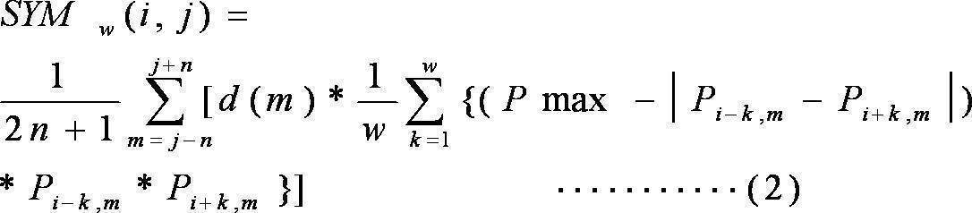

したがって、この物体検出装置により取得された対称性評価値を用いることで、少ない演算量で、精度良く、対称性の高い物体の検出を行うことができる。
なお、Pmaxの値は、特徴量抽出画像上の画素値の取り得る最大値であってもよいし、当該最大値以上の所定の値であってもよい。
第14の発明は、第13の発明であって、重み付け関数d(m)は、
(1)d(m)=1、
(2)d(m)=n+1-|m-j|、および
(3)d(m)=c1×exp(-c2×(m-j)^2)
(c1およびc2は、所定の正の係数)
のいずれか一つである。
(1)d(m)=1、
(2)d(m)=n+1-|m-j|、および
(3)d(m)=c1×exp(-c2×(m-j)^2)
(c1およびc2は、所定の正の係数)
のいずれか一つである。
これにより、この物体検出装置では、第2方向に積算する場合の重み付けを所望のものに設定することができる。例えば、(1)d(m)=1の場合、第2方向に積算する場合の重み付けは均等であり、(2)d(m)=n+1-|m-j|の場合、第2方向に積算する場合の重み付けは、対称性評価領域の第2方向における中央付近のときに、強くなされ(m=jのとき、最も強く重み付けされる。)、(3)d(m)=c1×exp(-c2×(m-j)^2)の場合、第2方向に積算する場合の重み付けは、対称性評価領域の第2方向における中央付近のときに、強くなされる(m=jのとき、最も強く重み付けされる。)。
第15の発明は、第12から第14のいずれかの発明であって、対称性評価部は、SYMw(i、j)の最大値maxSYMを取得するとともに、SYMw(i、j)が最大値となるときの対称性評価領域の第1方向の幅2w+1に基づいて、対称幅を決定する。
これにより、この物体検出装置では、所定の画像領域の対称性が高いと判定した場合、対称性が高いと判定した画像領域の大きさ(例えば、第1方向の幅)も同時に取得することができる。つまり、この物体検出装置では、画像に含まれる物体の対称性を利用して、物体の位置と大きさを同時に抽出することが可能である。
したがって、この物体検出装置では、少ない演算量で、精度良く、対称性の高い物体の検出を行うことができる。
第16の発明は、第10から第15のいずれかの発明であって、対称性評価部は、画像の第1方向の画素数をH(Hは自然数)とすると、
(1)注目画素の第1方向の位置を示す列iが(H/2)以下の場合、対称性評価領域の第1方向の幅の半分であるwを、1≦w≦(i-1)の範囲で変化させて、対称性評価値を算出し、
(2)注目画素の第1方向の位置を示す列iが(H/2)より大きい場合、対称性評価領域の第1方向の幅の半分であるwを、1≦w≦(H-i)の範囲で変化させて、対称性評価値を算出する。
(1)注目画素の第1方向の位置を示す列iが(H/2)以下の場合、対称性評価領域の第1方向の幅の半分であるwを、1≦w≦(i-1)の範囲で変化させて、対称性評価値を算出し、
(2)注目画素の第1方向の位置を示す列iが(H/2)より大きい場合、対称性評価領域の第1方向の幅の半分であるwを、1≦w≦(H-i)の範囲で変化させて、対称性評価値を算出する。
これにより、この物体検出装置では、対称性評価領域が、注目画素を中心にした左右対称な領域であることが保証されるとともに、注目画素を中心にした左右対称な領域のうち最大の領域を用いて対称性評価値を算出することができる。
第17の発明は、第1の発明であって、対称性評価部は、特徴量抽出画像に対して、処理対象である注目画素ごとに、画像上の第1方向についての対称性を評価するための領域である対称性評価領域を第1方向と直交する第2方向の所定の軸である中心軸を中心として対称となるように設定し、対称性評価領域の大きさを変化させながら、対称性評価領域に含まれ、中心軸について対称となる位置に存在する画素群の画像特徴量の相関値に対して、画素群の中心軸からの距離に基づく重み付けを行った値を導出することで、第1方向の対称性の度合いを示す対称性評価値を取得する。
これにより、この物体検出装置では、中心軸について対称となる位置に存在する画素群の画像特徴量の相関値に対して、画素群の中心軸からの距離に基づく重み付けを行った値に基づいて、対称性評価値を取得するので、第1方向の対称性の評価を高い精度で行うことができる。
したがって、この物体検出装置により取得された対称性評価値を用いることで、少ない演算量で、精度良く、対称性の高い物体の検出を行うことができる。
なお、「対称性評価領域」の第2方向(第1方向と直交する方向)の幅は、1画素分の幅であってもよいし、また、複数画素分の幅であってもよい。
また、「中心軸について対称となる位置に存在する画素群」とは、画像上において、
(1)中心軸から、互いに逆方向に、等距離離れた2つ画素(例えば、第1方向を水平方向とすると、中心軸から水平方向左に距離kだけ離れた画素P1および中心軸から水平方向右に距離kだけ離れた画素P2の合計2つの画素)や、
(2)中心軸から、互いに逆方向に、等距離離れた複数の画素(例えば、第1方向を水平方向とすると、中心軸から水平方向左に距離kだけ離れたn個の画素群および中心軸から水平方向右に距離kだけ離れたn個の画素群)を含む概念である。
また、「画像特徴量の相関値」とは、画像特徴量の相関の程度を示す値であり、例えば、特徴量抽出画像上の2つの画素の画素値の相関が高い場合(例えば、当該2つの画素値の差が小さい場合や当該2つの画素値の比が「1」に近い場合)に、相関が高いことを示す値をとるものである。
また、「中心軸について対称となる位置に存在する画素群」とは、画像上において、
(1)中心軸から、互いに逆方向に、等距離離れた2つ画素(例えば、第1方向を水平方向とすると、中心軸から水平方向左に距離kだけ離れた画素P1および中心軸から水平方向右に距離kだけ離れた画素P2の合計2つの画素)や、
(2)中心軸から、互いに逆方向に、等距離離れた複数の画素(例えば、第1方向を水平方向とすると、中心軸から水平方向左に距離kだけ離れたn個の画素群および中心軸から水平方向右に距離kだけ離れたn個の画素群)を含む概念である。
また、「画像特徴量の相関値」とは、画像特徴量の相関の程度を示す値であり、例えば、特徴量抽出画像上の2つの画素の画素値の相関が高い場合(例えば、当該2つの画素値の差が小さい場合や当該2つの画素値の比が「1」に近い場合)に、相関が高いことを示す値をとるものである。
第18の発明は、第17の発明であって、対称性評価部は、対称性評価値が第1方向についての対称性が最大であることを示す値である場合の対称性評価領域の大きさに基づいて、第1方向に関する対称幅を決定する。
この物体検出装置では、入力画像の画像特徴量を抽出した画像に対して、第1方向についての対称性を評価するために、対称性評価領域の大きさ(例えば、第1方向の幅)を変化させながら対称性の評価を行う。したがって、この物体検出装置では、所定の画像領域の対称性が高いと判定した場合、対称性が高いと判定した画像領域の大きさ(例えば、第1方向の幅)も同時に取得することができる。つまり、この物体検出装置では、画像に含まれる物体の対称性を利用して、物体の位置と大きさを同時に抽出することが可能である。
したがって、この物体検出装置では、少ない演算量で、精度良く、対称性の高い物体の検出を行うことができる。
第19の発明は、第17の発明であって、対称性評価部は、特徴量抽出画像上の画素値が0または正の値をとり、画像特徴量が大きい程、大きな値をとるものとし、特徴量抽出画像上の画素値の取り得る最大値以上の所定の値をPmaxとし、特徴量抽出画像上の座標(i,j)の注目画素の画素値をPiとし、注目画素から第1方向の一方向である第1探索方向(例えば、第1方向を水平方向としたとき、第1探索方向は水平方向左方向である。)にk画素(kは自然数)離れた画素の画素値をPi-kとし、注目画素から第1方向の第1探索方向と逆方向である第2検索方向(例えば、第1方向を水平方向としたとき、第2探索方向は水平方向右方向である。)にk画素離れた画素の画素値をPi+kとし、対称性評価領域の第1方向の幅を2w+1とし、所定の閾値をThとし、注目画素からの距離kについての重み付け関数をc(k)とするとき、対称性評価領域の第1方向の幅2w+1(wは自然数)を変化させながら、下記(数式4)に基づいて、注目画素の対称性評価値を算出する。

これにより、この物体検出装置では、(数式4)により、中心軸について対称となる位置に存在する画素群の画像特徴量の相関値(Pmax-fi(k))に対して、画素群の中心軸からの距離に基づく重み付け(c(k)による重み付け)を行った値に基づいて、対称性評価値を取得するので、第1方向の対称性の評価を高い精度で行うことができる。
したがって、この物体検出装置により取得された対称性評価値を用いることで、少ない演算量で、精度良く、対称性の高い物体の検出を行うことができる。
なお、上記(数式4)に相当する処理において、SYMw(i、j)が取り得る範囲を調整するために、ゲイン調整(係数調整)や、正規化処理や、所定の値でのクリップ処理等を行うようにしてもよい(上記(数式4)を修正した処理を行ってもよい)。
また、Pmaxの値は、特徴量抽出画像上の画素値の取り得る最大値であってもよいし、当該最大値以上の所定の値であってもよい。
第20の発明は、第19の発明であって、対称性評価部は、SYMw(i、j)の最大値maxSYMを取得するとともに、SYMw(i、j)が最大値となるときの対称性評価領域の第1方向の幅2w+1に基づいて、対称幅を決定する。
これにより、この物体検出装置では、所定の画像領域の対称性が高いと判定した場合、対称性が高いと判定した画像領域の大きさ(例えば、第1方向の幅)も同時に取得することができる。つまり、この物体検出装置では、画像に含まれる物体の対称性を利用して、物体の位置と大きさを同時に抽出することが可能である。
したがって、この物体検出装置では、少ない演算量で、精度良く、対称性の高い物体の検出を行うことができる。
第21の発明は、第17または第18の発明であって、対称性評価部は、対称性評価領域に含まれ、中心軸について対称となる位置に存在する画素群の画像特徴量の相関値に対して、画素群の中心軸からの距離および画素群の画像特徴量に基づく重み付けを行った値を導出することで、第1方向の対称性の度合いを示す対称性評価値を取得することで、第1方向の対称性の度合いを示す対称性評価値を取得する。
これにより、この物体検出装置では、対称性評価領域に含まれる画素の画像特徴量および画像上の位置の両方に基づいて、第1方向の対称性の度合いを示す対称性評価値を取得することができる。
第22の発明は、第21の発明であって、対称性評価部は、特徴量抽出画像上の画素値が0または正の値をとり、画像特徴量が大きい程、大きな値をとるものとし、特徴量抽出画像上の画素値の取り得る最大値以上の所定の値をPmaxとし、特徴量抽出画像上の座標(i,j)の注目画素の画素値をPiとし、注目画素から第1方向の一方向である第1探索方向にk画素(kは自然数)離れた画素の画素値をPi-kとし、注目画素から第1方向の第1探索方向と逆方向である第2検索方向にk画素離れた画素の画素値をPi+kとし、対称性評価領域の第1方向の幅を2w+1とし、所定の閾値をThとし、注目画素からの距離kについての重み付け関数をc(k)とするとき、対称性評価領域の第1方向の幅2w+1(wは自然数)を変化させながら、下記(数式5)に基づいて、注目画素の対称性評価値を算出する。

したがって、この物体検出装置により取得された対称性評価値を用いることで、少ない演算量で、精度良く、対称性の高い物体の検出を行うことができる。
なお、Pmaxの値は、特徴量抽出画像上の画素値の取り得る最大値であってもよいし、当該最大値以上の所定の値であってもよい。
第23の発明は、第22の発明であって、対称性評価部は、SYMw(i、j)の最大値maxSYMを取得するとともに、SYMw(i、j)が最大値となるときの対称性評価領域の第1方向の幅2w+1に基づいて、対称幅を決定する。
これにより、この物体検出装置では、所定の画像領域の対称性が高いと判定した場合、対称性が高いと判定した画像領域の大きさ(例えば、第1方向の幅)も同時に取得することができる。つまり、この物体検出装置では、画像に含まれる物体の対称性を利用して、物体の位置と大きさを同時に抽出することが可能である。
したがって、この物体検出装置では、少ない演算量で、精度良く、対称性の高い物体の検出を行うことができる。
第24の発明は、第17または第18の発明であって、対称性評価部は、特徴量抽出画像上の画素値が0または正の値をとり、画像特徴量が大きい程、大きな値をとるものとし、特徴量抽出画像上の画素値の取り得る最大値以上の所定の値をPmaxとし、特徴量抽出画像上の座標(i,j)の注目画素の画素値をPiとし、注目画素から第1方向の一方向である第1探索方向にk画素(kは自然数)離れた画素の画素値をPi-kとし、注目画素から第1方向の第1探索方向と逆方向である第2検索方向にk画素離れた画素の画素値をPi+kとし、対称性評価領域の第1方向の幅を2w+1とし、対称性評価領域の第2方向の幅を2n+1とし、所定の閾値をThとし、注目画素からの距離kについての重み付け関数をc(k)とするとき、対称性評価領域の第1方向の幅2w+1(wは自然数)を変化させながら、下記(数式6)または(数式7)に基づいて、注目画素の対称性評価値を算出する。


なお、Pmaxの値は、特徴量抽出画像上の画素値の取り得る最大値であってもよいし、当該最大値以上の所定の値であってもよい。
第25の発明は、第24の発明であって、対称性評価部は、SYMw(i、j)の最大値maxSYMを取得するとともに、SYMw(i、j)が最大値となるときの対称性評価領域の第1方向の幅2w+1に基づいて、対称幅を決定する。
これにより、この物体検出装置では、所定の画像領域の対称性が高いと判定した場合、対称性が高いと判定した画像領域の大きさ(例えば、第1方向の幅)も同時に取得することができる。つまり、この物体検出装置では、画像に含まれる物体の対称性を利用して、物体の位置と大きさを同時に抽出することが可能である。
したがって、この物体検出装置では、少ない演算量で、精度良く、対称性の高い物体の検出を行うことができる。
第26の発明は、第17または第18の発明であって、対称性評価部は、特徴量抽出画像上の画素値が0または正の値をとり、画像特徴量が大きい程、大きな値をとるものとし、特徴量抽出画像上の画素値の取り得る最大値以上の所定の値をPmaxとし、特徴量抽出画像上の座標(i,j)の注目画素の画素値をPiとし、注目画素から第1方向の一方向である第1探索方向にk画素(kは自然数)離れた画素の画素値をPi-kとし、注目画素から第1方向の第1探索方向と逆方向である第2検索方向にk画素離れた画素の画素値をPi+kとし、対称性評価領域の第1方向の幅を2w+1とし、対称性評価領域の第2方向の幅を2n+1とし、所定の閾値をThとし、注目画素からの距離kについての重み付け関数をc(k)とするとき、対称性評価領域の第1方向の幅2w+1(wは自然数)を変化させながら、下記(数式8)または(数式9)に基づいて、注目画素の対称性評価値を算出する。


第27の発明は、第26の発明であって、対称性評価部は、SYMw(i、j)の最大値maxSYMを取得するとともに、SYMw(i、j)が最大値となるときの対称性評価領域の第1方向の幅2w+1に基づいて、対称幅を決定する。
これにより、この物体検出装置では、所定の画像領域の対称性が高いと判定した場合、対称性が高いと判定した画像領域の大きさ(例えば、第1方向の幅)も同時に取得することができる。つまり、この物体検出装置では、画像に含まれる物体の対称性を利用して、物体の位置と大きさを同時に抽出することが可能である。
したがって、この物体検出装置では、少ない演算量で、精度良く、対称性の高い物体の検出を行うことができる。
第28の発明は、第19、第20、第22から第26のいずれかの発明であって、重み付け関数c(k)は、kについての単調増加関数である。
これにより、この物体検出装置では、注目画素からの距離が大きい程、大きな重み付けを行い、対称性評価値を算出する。したがって、この物体検出装置では、対称軸から離れた位置に存在する対称性の高い領域(物体)を精度良く、検出することができる。
なお、「単調増加関数」とは、厳密な単調増加関数に限定されず、例えば、一部単調でない区間kについて一定となるがあってもよく(例えば、一部に不変区間(一定値をとる区間)があってよい)、大局的にみたときに増加する関数(例えば、平滑化処理(LPF処理等)を行ったときに単調増加関数になる関数)を含む概念である。
第29の発明は、第19、第20、第22から第26のいずれかの発明であって、重み付け関数をc(k)は、kについての単調減少関数である。
これにより、この物体検出装置では、注目画素からの距離が小さい程、大きな重み付けを行い、対称性評価値を算出する。したがって、この物体検出装置では、対称軸近傍に存在する対称性の高い領域(物体)を精度良く、検出することができる。
なお、「単調減少関数」とは、厳密な単調減少関数に限定されず、例えば、一部単調でない区間kについて一定となるがあってもよく(例えば、一部に不変区間(一定値をとる区間)があってよい)、大局的にみたときに減少する関数(例えば、平滑化処理(LPF処理等)を行ったときに単調減少関数になる関数)を含む概念である。
第30の発明は、第17から第29までのいずれかの発明であって、対称性評価部は、画像の第1方向の画素数をH(Hは自然数)とすると、
(1)注目画素の第1方向の位置を示す列iが(H/2)以下の場合、対称性評価領域の第1方向の幅の半分であるwを、1≦w≦(i-1)の範囲で変化させて、対称性評価値を算出し、
(2)注目画素の第1方向の位置を示す列iが(H/2)より大きい場合、対称性評価領域の第1方向の幅の半分であるwを、1≦w≦(H-i)の範囲で変化させて、対称性評価値を算出する。
(1)注目画素の第1方向の位置を示す列iが(H/2)以下の場合、対称性評価領域の第1方向の幅の半分であるwを、1≦w≦(i-1)の範囲で変化させて、対称性評価値を算出し、
(2)注目画素の第1方向の位置を示す列iが(H/2)より大きい場合、対称性評価領域の第1方向の幅の半分であるwを、1≦w≦(H-i)の範囲で変化させて、対称性評価値を算出する。
これにより、この物体検出装置では、対称性評価領域が、注目画素を中心にした左右対称な領域であることが保証されるとともに、注目画素を中心にした左右対称な領域のうち最大の領域を用いて対称性評価値を算出することができる。
第31の発明は、第1から第30の発明であって、画像特徴量は、画像のエッジ強度である。
この物体検出装置では、画像のエッジ成分を考慮して対称性の高い物体を検出することができるので、物体の輪郭(外枠)についての対称性の高い物体を、精度良く検出することができる。
第32の発明は、第1から第30の発明であって、画像特徴量は、画像の特定の色成分の強度である。
この物体検出装置では、画像の特定色成分(例えば、赤色成分)を考慮して対称性の高い物体を検出することができるので、特定の色について、対称性の高い物体を、精度良く検出することができる。
第33の発明は、画像入力ステップと、画像特徴量抽出ステップと、対称性評価ステップと、中心検出ステップと、物体領域検出ステップと、を備える物体検出方法をコンピュータに実行させるためのプログラムである。
画像入力ステップは、画像を入力する。
画像特徴量抽出ステップは、画像から所定の画像特徴量を抽出して特徴量抽出画像を生成する。
対称性評価ステップは、特徴量抽出画像に対して、処理対象である注目画素ごとに、画像上の第1方向に関する対称性を評価するとともに、第1方向に関する対称幅を算出する。
中心検出ステップは、複数の評価画素の中で対称性が所定の基準を上回る画素を対称中心画素として検出する。
物体領域検出ステップは、対称中心画素の対称幅に基づいて前記画像に含まれる対称性を有する物体の第1方向に関する物体幅を検出し、対称中心画素の第1方向と直交する第2方向に関する分布に基づいて物体の第2方向に関する物体幅を検出する。
これにより、第1の発明と同様の効果を奏する物体検出方法をコンピュータに実行させるためのプログラムを実現することができる。
第34の発明は、第33の発明であって、対称性評価ステップは、特徴量抽出画像に対して、処理対象である注目画素ごとに、画像上の第1方向についての対称性を評価するための領域である対称性評価領域を第1方向と直交する第2方向の中心軸を中心として対称となるように設定し、対称性評価領域の大きさを変化させながら、対称性評価領域に含まれ、中心軸について対称となる位置に存在する画素群の画像特徴量の相関値に対して、画素群の画像特徴量による重み付けを行った値を導出することで、第1方向の対称性の度合いを示す対称性評価値を取得する。
これにより、第10の発明と同様の効果を奏する物体検出方法をコンピュータに実行させるためのプログラムを実現することができる。
第35の発明は、第33の発明であって、対称性評価ステップは、特徴量抽出画像に対して、処理対象である注目画素ごとに、画像上の第1方向についての対称性を評価するための領域である対称性評価領域を第1方向と直交する第2方向の所定の軸である中心軸を中心として対称となるように設定し、対称性評価領域の大きさを変化させながら、対称性評価領域に含まれ、中心軸について対称となる位置に存在する画素群の画像特徴量の相関値に対して、画素群の中心軸からの距離に基づく重み付けを行った値を導出することで、第1方向の対称性の度合いを示す対称性評価値を取得する。
これにより、第17の発明と同様の効果を奏する物体検出方法をコンピュータに実行させるためのプログラムを実現することができる。
本発明によれば、入力画像上の物体の対称性を利用し、物体の位置と大きさを検出することで、少ない演算量で物体に関する重要な情報(例えば、物体の位置と大きさについての情報)を検出する技術を実現することができる。
[第1実施形態]
<1.1:物体検出システム>
以下、図面を参照しつつ本発明の第1実施形態について説明する。図1は、被写体として車両110を含む撮影画像100を示す図である。車両110は、左右のテールランプ111L・111Rを備えている。左右のテールランプ111L・111Rは、車両110の車幅方向に関する中心軸112に対して左右対称に配置されている。本実施の形態において、画像に含まれる左右対称性を利用して、車両110などの物体が検出可能となっている。
<1.1:物体検出システム>
以下、図面を参照しつつ本発明の第1実施形態について説明する。図1は、被写体として車両110を含む撮影画像100を示す図である。車両110は、左右のテールランプ111L・111Rを備えている。左右のテールランプ111L・111Rは、車両110の車幅方向に関する中心軸112に対して左右対称に配置されている。本実施の形態において、画像に含まれる左右対称性を利用して、車両110などの物体が検出可能となっている。
図2は、第1実施形態に係る物体検出システム10を示すブロック図である。物体検出システム10は、撮像装置1、物体検出装置2およびモニタ3を備えている。
撮像装置1は、たとえばCCDなどの撮像素子を備えている。撮像装置1により撮像された画像は、物体検出装置2に入力される。
たとえば、物体検出装置2は車両に搭載される。撮像装置1が車両の前部に装備される場合には、撮像装置1は、車両の前方の画像を撮像する。あるいは、撮像装置1は車両の後部に装備され、車両の後方の画像を撮像する。モニタ3は、運転席に装備される。たとえば、モニタ3は、ナビゲーションシステム用のモニタと兼用される。
図2に示すように、物体検出装置2は、画像入力部21、メモリ22および物体検出部23を備えている。
画像入力部21は、撮像装置1から出力された画像を入力する。たとえば、撮像装置1がRGBベイヤ配列の色フィルタを備えたCCDである場合、画像入力部21は、R信号、G信号あるいはB信号を含む画素信号列を入力する。画像入力部21は、入力した画像をメモリ22に格納する。
物体検出部23は、メモリ22に格納された画像に対して画像処理を実行し、画像に含まれる対称性を有する物体を検出する。物体検出部23は、特徴領域抽出部231、対称性評価部232、対称幅検出部233、中心検出部234、物体幅検出部235および合成部236を備えている。
特徴領域抽出部231、対称性評価部232、対称幅検出部233、中心検出部234、物体幅検出部235および合成部236は、ハードウェア回路により構成されている。しかし、これら各処理部の全部あるいは一部がソフトウェア処理により実現されていてもよい。つまり、これら各処理部が、ソフトウェアと、ソフトウェアを実行可能なCPUおよびメモリ等のハードウェアとで構成されていてもよい。
物体検出部23より出力された画像は、モニタ3に表示される。モニタ3に表示される画像には、物体の領域を示す領域枠が合成される。これにより、運転者は、物体を容易に認識することができる。
<1.2:物体検出処理>
次に、図2および図3A~図3Gを参照しながら、物体検出処理の流れを説明する。図3Aは、撮像装置1において撮像されたカラー画像100Aを示す図である。カラー画像100Aには、車両110が含まれている。車両110は、車両後部にテールランプ111L・111Rが取り付けられている。
次に、図2および図3A~図3Gを参照しながら、物体検出処理の流れを説明する。図3Aは、撮像装置1において撮像されたカラー画像100Aを示す図である。カラー画像100Aには、車両110が含まれている。車両110は、車両後部にテールランプ111L・111Rが取り付けられている。
画像入力部21は、カラー画像100Aを入力し、メモリ22に格納する。たとえば、撮像装置1が15fpsで画像を撮像する場合であれば、メモリ22には15fpsのカラー画像100Aが格納される。カラー画像100Aは、たとえば、RGB色空間の画像である。
特徴領域抽出部231は、メモリ22からカラー画像100Aを取得し、カラー画像100Aから輝度画像100Bを生成する。
図3Bは、輝度画像100Bを示す図である。たとえば、カラー画像100AがRGB色空間の画像であれば、特徴領域抽出部231は、カラー画像100AをYCbCr変換し、YCbCr色空間の画像からY信号の画像を抽出し、輝度画像100Bを生成する。
あるいは、RGB色空間のG信号を利用して輝度画像100Bを生成してもよい。R・B成分を有する画素については補間処理によりG信号を生成すればよい。
続いて、特徴領域抽出部231は、輝度画像100Bに対してエッジ検出処理を実行し、エッジ画像100Cを生成する。
図3Cは、エッジ画像100Cを示す図である。特徴領域抽出部231は、輝度画像100Bに微分処理を施すことでエッジ画像100Cを生成する。
次に、対称性評価部232は、エッジ画像100Cの対称性を評価する。以下、対称性の評価方法について説明する。
対称性評価部232は、図4に示す注目画素Piに関して対称性を評価する。注目画素Piは、エッジ画像100Cに含まれる画素である。注目画素Piは、エッジ画像100Cにおける座標(i、j)の画素を示している。以下の説明において、画素Pxという表記は、エッジ画像100Cにおける座標(x、j)の画素を示す。つまり、画素Pxという表記は、水平方向にx列目で、垂直方向にj行目の画素を示している。また、数式においては、Pxは、画素Pxにおける画素値を示すものとする。本実施の形態においては、Pxは0~255の範囲の値をとる。
図4には、画素の注目画素Piの左側に位置するw個の画素(Pi-w~Pi-1)、および、注目画素Piの右側に位置するw個の画素(Pi+1~Pi+w)が描かれている。この2w+1個の画素(Pi-w~Pi+w)の対称性を評価する演算式を(数式10)に示す。

(数式10)において、SYMw(i、j)は、対称性の評価値を示す。(数式10)において、kは、1~wまでの値をとる整数である。
画素Pi-kと画素Pi+kは、注目画素Piを中心として左右対称の位置にある画素である。画素Pi-kと画素Pi+kの画素値が等しいとき、その差分|Pi-k-Pi+k|は最小値0となる。このとき、(255-|Pi-k-Pi+k|)は、最大値255となる。つまり、(数式10)においては、対称性が高いほどSYMw(i、j)は、大きな値をとる。注目画素Piの左側w個の画素値と右側w個の画素値が完全に等しいとき、SYMw(i、j)は、最大値255をとる。
対称性評価部232は、注目画素Piに関して、wを変化させて、全てのwについてSYMw(i、j)を算出する。そして、対称性評価部232は、(数式11)に示すように、注目画素PiについてSYMw(i、j)の最大値maxSYMを算出する。

(数式11)において、Nはwの最大値である。エッジ画像100Cの水平方向の画素数をHとすると、注目画素の水平方向の位置を示す列iが(H/2)以下の場合には、Nは(i-1)である。注目画素の水平方向の位置を示す列iが(H/2)より大きい場合には、Nは(H-i)である。
また、対称幅検出部233は、最大値maxSYMを与えるwを、対称幅waとして取得する。つまり、SYMw(i、j)は、w=waのとき、最大値maxSYMをとる。対称幅waを用いて、maxSYMは、(数式12)のように表すことができる。

対称性評価部232は、対称性を評価する対象となる全ての評価画素について、(数式10)および(数式11)の演算を行い、図3Dに示す対称性マップ100Dを生成する。本実施の形態においては、評価画素としてエッジ画像100Cの全ての画素を利用している。つまり、エッジ画像100Cに含まれる全ての画素について、SYMw(i、j)を算出するとともに、maxSYMを算出している。
しかし、演算量を減らすために、あるいは、処理速度を向上させるために、エッジ画像100Cに含まれる一部の画素を評価画素として利用してもよい。たとえば、評価画素として水平(あるいは垂直)方向の奇数ラインのみ、あるいは偶数ラインのみを利用してもよい。あるいは、3ライン間隔で評価画素を選択するなど、評価画素の数を少なくしてもよい。
対称性マップ100Dは、各評価画素について、その評価画素について算出されたmaxSYMの値を成分とするマップである。各評価画素について、その評価画素について算出されたmaxSYMの値を画素値とする画像と考えてもよい。図3Dは、対称性マップ100Dを画像として描画している。
本実施の形態においては、評価画素としてエッジ画像100Cの全ての画素が利用されているので、対称性マップ100Dは、エッジ画像100Cの全画素の画素値をmaxSYMに置き換えたグレースケールの画像である。
上述したように、本実施の形態においては、SYMw(i、j)は、0~255の値を取り得る。したがって、対称性マップ100Dの各成分は、それぞれ0~255の値を取り得る。図3Dにおいて、白に近い色はSYMw(i、j)の値が大きい(255に近い)ことを示している。つまり、図3Dにおいて、白っぽい領域は対称性が高く評価された領域であり、対称となる物体の中心付近を示している。一方、図3Dにおいて、黒っぽい領域は対称性が高くない領域である。
対称幅検出部233は、対称性を評価する対象となる全ての評価画素について、図3Eに示す対称幅マップ100Eを生成する。
対称幅マップ100Eは、各評価画素についてmaxSYMを与える対称幅waを成分とするマップである。各評価画素について、対称幅waを画素値とする画像と考えてもよい。図3Eは、対称幅マップ100Eを画像として描画している。本実施の形態においては、評価画素としてエッジ画像100Cの全ての画素が利用されているので、対称幅マップ100Eは、エッジ画像100Cの全画素を対称幅waに置き換えたグレースケールの画像である。
上述したように、本実施の形態においては、対称幅waは1からNまでの値を取り得る。したがって、対称幅マップ100Eの各成分は、それぞれ1~Nの値を取り得る。Nの値は画素位置によって異なる。図3Eにおいて、色が白に近い領域は、対称幅waが大きい領域を示している。図3Eにおいて、色が黒に近い領域は、対称幅waが小さい領域を示している。
続いて中心検出部234は、対称性マップ100Dを参照し、対称中心マップ100Fを生成する。中心検出部234は、対称性マップ100Dの水平方向の各ラインについて、maxSYMの極大点を与える画素を対称中心画素として選択する。
図5は、対称性マップ100Dの水平方向の変化を示す図である。図5は、対称性マップ100Dの水平方向の1ラインについてmaxSYMの変化を表わす図である。この図では、水平方向位置を示す列(i座標)が、330、331、および332の3つの座標において、対称性マップ100Dが極大点となっている例を示す。中心検出部234は、水平方向の全てのラインについて極大点を与える座標を特定する。
図3Fは、中心検出部234に特定された対称中心画素をプロットした対称中心マップ100Fである。対称中心マップ100Fでは、対称中心画素に特定された座標に成分「1」を、対称中心画素に特定されなかった座標に成分「0」を与えた画像と見ることができる。図3Fにおいて、白色の部分が対称中心画素として特定された画素を示している。なお、極大点となる画素値を予め設定された閾値と比較し、閾値を上回る場合にのみ対称中心画素として特定するようにすればよい。これにより、細かな変動により生まれる極大点を排除することができる。
続いて物体幅検出部235は、エッジ画像100Cに含まれる対称性を有する物体の水平方向の幅および垂直方向の幅を検出する。
物体幅検出部235は、物体の水平方向の幅として、対称中心マップ100Fおよび対称幅マップ100Eを利用する。対称中心マップ100Fは、対称性を有する物体の中心軸を構成する画素に画素値「1」が与えられている。物体幅検出部235は、対称中心マップ100Fにおいて画素値「1」を有する画素を抽出し、その抽出された画素の対称幅を対称幅マップ100Eから取得する。本実施の形態においては、全ての対称中心画素について対称幅を取得する。同一の水平方向のラインに対称中心画素が複数存在する場合には、その平均値をその水平方向ラインに関する対称幅とする。そして、全ての水平方向のラインについて対称幅を取得し、その最大幅を、物体幅として検出する。同一の水平方向のラインに対称中心画素が複数存在する場合には、その最大値をその水平方向に関する対称幅としてもよい。
別の方法として、物体幅検出部235は、各水平方向のラインについて対称幅を決定した後、その平均値を物体幅としてもよい。対称幅の最大値あるいは平均値を物体の水平方向の幅とする場合、物体の幅を1つの値で示すことになる。これに対して、物体幅を水平方向のラインごとに決定してもよい。
物体幅検出部235は、物体の垂直方向の幅として、対称中心画素の垂直方向の幅を利用する。つまり、物体幅検出部235は、垂直方向に連続して配列された対称中心画素の上端を物体の上端として特定し、垂直方向に連続して配列された対称中心画素の下端を物体の下端として特定する。
合成部236は、物体幅検出部235において特定された物体の水平方向の幅と垂直方向の幅を示す矩形画像を生成し、カラー画像100Aに合成する。図3Gは、対称性を有する物体である車両110の領域を示す領域枠130がカラー画像100Aに合成された合成画像100Gを示している。なお、水平方向ラインごとに物体幅が決定された場合には、領域枠は矩形ではなく、物体の外形に沿うような形状となる。
このように、本実施の形態によれば、画像に含まれる物体の対称性を利用して、物体の位置と大きさを同時に抽出することが可能である。
[第2実施形態]
第1実施形態においては、特徴領域抽出部231は、物体の特徴量としてエッジ成分を利用した。そして、特徴量として抽出したエッジ成分に基づき、対称性の評価を行った。
[第2実施形態]
第1実施形態においては、特徴領域抽出部231は、物体の特徴量としてエッジ成分を利用した。そして、特徴量として抽出したエッジ成分に基づき、対称性の評価を行った。
第2実施形態においては、特徴領域抽出部231は、物体の特徴量として特定の色成分を利用する。たとえば、特徴領域抽出部231は、特徴量として赤色成分を抽出する。特徴領域抽出部231は、たとえば、メモリ22に格納されているRGB色空間の画像をYCbCr色空間の画像に変換する。特徴領域抽出部231は、YCbCr色空間の画像からCr成分を抽出し、Cr画像を生成する。特徴領域抽出部231は、Cr画像に対してさらに赤色成分の強調処理を行い、R成分画像を生成する。
この後の処理は第1実施形態と同様である。第1実施形態におけるエッジ画像をR成分画像に置き換えた上で、同様の処理を実行し、対称性のある物体を検出する。このように、本実施の形態においても、画像の特定の色成分を利用し、画像に含まれる物体の対称性を利用し、物体の位置と大きさを同時に検出することができる。
図6は、第2実施形態においてモニタ3に表示された合成画像100Gを示す図である。第1実施形態においては、エッジ成分により物体の対称性を評価したので、車両の全体が物体の大きさとして抽出されている。これに対して第2実施形態においては、テールランプの赤色を中心に物体の対称性が評価されたので、テールランプを含む領域が抽出されていることが分かる。
第1実施形態と第2実施形態の両方を組み合わせてもよい。エッジ画像に対して物体の垂直方向および水平方向の幅および位置を特定する。さらに、特定の色成分画像を利用して物体の垂直方向および水平方向の幅および位置を特定する。そして、それらの平均値をとることで物体の位置および大きさを特定することができる。あるいは、エッジ画像に基づいて求められた値と色成分に基づいて求められた値のいずれかに重みづけを行って物体の位置および大きさを特定してもよい。
[第3実施形態]
第1実施形態においては、水平方向に関して対称性を有する物体を検出した。同様に、垂直方向に関して対称性を有する物体を検出してもよい。つまり、第1実施形態における水平方向の処理と垂直方向の処理を逆にすることで垂直方向に関して対称性を有する物体を検出してもよい。
第1実施形態においては、水平方向に関して対称性を有する物体を検出した。同様に、垂直方向に関して対称性を有する物体を検出してもよい。つまり、第1実施形態における水平方向の処理と垂直方向の処理を逆にすることで垂直方向に関して対称性を有する物体を検出してもよい。
[第4実施形態]
第1実施形態においては、水平方向に関して対称性を有する物体を検出した。これに対して、水平方向および垂直方向の両方に関して対称性を有する物体を検出対象から除外し、水平方向にのみ対称性を有する物体を検出してもよい。
第1実施形態においては、水平方向に関して対称性を有する物体を検出した。これに対して、水平方向および垂直方向の両方に関して対称性を有する物体を検出対象から除外し、水平方向にのみ対称性を有する物体を検出してもよい。
(数式10)に示した対称性の評価値を水平方向および垂直方向の両方について演算する。そして、算出された水平方向の評価値をSYMwH(i、j)とし、垂直方向の評価値をSYMwV(i、j)とする。
そして、(数式13)に示す演算を行い、水平方向と垂直方向の両方の対称性を加味した比較値SYMwC(i、j)を算出する。

[第5実施形態]
第5実施形態について、図面を参照しながら、以下、説明する。
<5.1:物体検出システムの構成>
図7は、第5実施形態に係る物体検出システム1000を示すブロック図である。物体検出システム1000は、撮像装置1と、物体検出装置2Aと、表示装置3とを備えている。
第5実施形態について、図面を参照しながら、以下、説明する。
<5.1:物体検出システムの構成>
図7は、第5実施形態に係る物体検出システム1000を示すブロック図である。物体検出システム1000は、撮像装置1と、物体検出装置2Aと、表示装置3とを備えている。
撮像装置1は、被写体からの光を集光する光学系(不図示)と、当該光学系により集光された被写体光を光電変換により画像信号(電気信号)として取得する撮像素子(たとえばCCDイメージセンサやCMOSイメージセンサ)(不図示)とを備えている。撮像装置1は、撮像素子により撮像した画像(画像信号)を、物体検出装置2Aに出力する。
物体検出装置2Aは、撮像装置1から出力される画像信号を入力とし、入力された画像信号により形成される画像中に含まれる対称性を有する物体を検出し、検出した結果を示す画像(画像信号)を表示装置3に出力する。
たとえば、物体検出装置2Aは車両に搭載される。撮像装置1が車両の前部に装備される場合には、撮像装置1は、車両の前方の画像(シーン)を撮像する。あるいは、撮像装置1は車両の後部に装備され、車両の後方の画像(シーン)を撮像する。
表示装置(モニタ)3は、例えば、車両の運転席に装備される。表示装置3は、ナビゲーションシステム用のモニタと兼用してもよい。
図7に示すように、物体検出装置2Aは、画像入力部21Aと、物体検出部22Aと、合成部23Aとを備えている。
画像入力部21Aは、撮像装置1から出力される画像(画像信号)を入力する。たとえば、撮像装置1がRGBベイヤ配列の色フィルタを備えたCCDイメージセンサを用いる撮像装置である場合、画像入力部21Aには、例えば、R成分信号、G成分信号およびB成分信号を含む画素信号列が入力される。画像入力部21Aは、入力された画像信号を、必要に応じて、所定の形式に変換し、変換した画像信号(変換されない場合は、無変換の画像信号)を物体検出部22Aに出力する。また、画像入力部21Aは、入力された画像信号を、合成部23Aに出力する。
なお、「所定の形式への変換」とは、例えば、色空間の変換(例えば、RGB色空間からYCbCr色空間への変換)である。画像入力部21Aは、入力されたRGB色空間の画像信号(R成分信号、G成分信号およびB成分信号)を、必要に応じて、例えば、YCbCr色空間の信号(Y成分信号、Cb成分信号およびCr成分信号)に変換する。
なお、以下では、説明便宜のため、画像入力部21Aにおいて、入力されたRGB色空間の画像信号(R成分信号、G成分信号およびB成分信号)が、YCbCr色空間の信号(Y成分信号、Cb成分信号およびCr成分信号)に変換される場合を例に説明する。
物体検出部22Aは、画像入力部21Aから出力される画像(画像信号)を入力とし、入力された画像に対して所定の画像処理を実行し、画像(画像信号により形成される画像(例えば、フレーム画像))に含まれる対称性を有する物体を検出する(対称性を有する物体に相当する画像領域を特定する)。そして、物体検出部22Aは、検出結果(例えば、対称性を有する物体に相当する画像領域を特定するための情報)を合成部23Aに出力する。
物体検出部22Aは、図8に示すように、画像特徴量抽出部221と、対称性評価部222と、中心検出部223と、物体領域検出部224と、を備える。
画像特徴量抽出部221は、画像入力部21Aから出力される画像から画像特徴量を算出(抽出)する。具体的には、画像特徴量抽出部221は、例えば、画像入力部21Aから出力されるY成分信号(輝度成分信号)により形成されるY成分画像(輝度成分画像)から、Sobelフィルタ等を用いた微分演算処理により、エッジ成分を画像特徴量として抽出する。そして、画像特徴量抽出部221は、抽出したエッジ成分を各画素の画素値とする画像(特徴量抽出画像)を画像特徴量抽出画像として、対称性評価部222および物体領域検出部224に出力する。
なお、以下では、説明便宜のため、特徴量抽出画像の各画素の画素値は、抽出対象の画像特徴量の程度が大きい程、大きな値をとるものとして、説明する。
対称性評価部222は、画像特徴量抽出部221が抽出した画像(特徴量抽出画像)を入力とする。そして、対称性評価部222は、当該特徴量抽出画像から、各画素において、画像上の所定の方向(例えば、水平方向)の対称性を評価(判定)するとともに対称性の高い画像領域の幅(上記所定の方向(例えば、水平方向)の幅)を決定(推定)する。そして、対称性評価部222は、画素ごとに、当該画素(処理対象画素)を特定する情報(例えば、画素の座標)と、評価(判定)した対称性の度合いを示す値(または当該値と相関のある値)と、を対応付けた対称性評価マップデータを取得する。
さらに、対称性評価部222は、画素ごとに、当該画素(処理対象画素)を特定する情報(例えば、画素の座標)と、決定(推定)した対称性の高い画像領域の幅(上記所定の方向(例えば、水平方向)の幅)を示す値(または当該値と相関のある値)と、を対応づけた対称幅マップデータを取得する。
そして、対称性評価部222は、取得した対称性評価マップデータを中心検出部223に出力する。また、対称性評価部222は、取得した対称幅マップデータを物体領域検出部224に出力する。
中心検出部223は、対称性評価部222により取得された対称性評価マップデータを入力とする。中心検出部223は、対称性評価マップデータを2次元画像(対称性評価値を各画素の画素値としてマッピングし生成した画像)としたとき、当該画像上の所定の方向(例えば、水平方向)において極大値(または極大値付近の値)をとる画素または画素領域を特定し、特定した画素または画素領域に基づいて、対称性の高い物体の中心軸の位置を決定(推定)する。そして、中心検出部223は、決定(推定)した対称性の高い物体の中心軸の(画像上の)位置に関する情報を物体領域検出部224に出力する。
物体領域検出部224は、対称性評価部222により取得された対称幅マップデータと、中心検出部223から出力される対称性の高い物体の中心軸の(画像上の)位置に関する情報と、を入力とする。物体領域検出部224は、対称幅マップデータと、対称性の高い物体の中心軸の(画像上の)位置に関する情報と、に基づいて、対称性の高い物体を検出し、検出した対称性の高い物体の画像上の領域を特定する。そして、物体領域検出部224は、特定した対称性の高い物体の画像上の領域についての情報を合成部23Aに出力する。
合成部23Aは、画像入力部21Aから出力される画像と、物体検出部22Aの物体領域検出部224から出力される検出した対称性の高い物体の画像上の領域を特定する情報と、を入力とする。合成部23Aは、物体領域検出部224から出力される検出した対称性の高い物体の画像上の領域を特定する情報に基づいて、画像入力部21Aから出力される画像上に、対称性の高い物体に相当する画像領域を明示する画像を生成(合成)する。合成部23Aは、例えば、画像入力部21Aから出力される画像上に、対称性の高い物体に相当する画像領域を明示する四角い枠が表示されるように画像を生成(合成)する。そして、合成部23Aは、合成した画像を表示装置3に出力する。
表示装置3は、物体検出装置2の合成部23Aから出力される画像を入力とし、当該画像を表示する。
<5.2:物体検出システムの動作>
以上のように構成された物体検出システム1000の動作について、図面を用いながら、以下、説明する。
以上のように構成された物体検出システム1000の動作について、図面を用いながら、以下、説明する。
図9は、物体検出システム1000において実行される物体検出処理の各段階において取得される画像の一例を示した図である。
図10Aは、撮像装置1により撮像され、物体検出装置2に入力される撮像画像101を示す図である。
撮像画像101は、図10Aに示すように、被写体として車両110を含む。車両110は、左右のテールランプ111L・111Rを備えている。左右のテールランプ111L・111Rは、車両110の車幅方向に関する中心軸112に対して左右対称に配置されている。
以下では、撮像装置1において、図10Aに示した撮像画像101が取得され、撮像画像101が物体検出装置2で処理される場合を例に説明する。
撮像装置1で取得された撮像画像101(撮像画像101を形成する画像信号)は、物体検出装置2の画像入力部21Aに入力される。なお、撮像画像101は、R成分信号、G成分信号およびB成分信号により形成される画像であるものとする。
画像入力部21Aは、入力された撮像画像に対して、色空間変換処理を行う。具体的には、画像入力部21Aは、RGB色空間を、例えば、YCbCr色空間に変換する処理を行い、撮像画像101を形成する、R成分信号、G成分信号およびB成分信号を、Y成分信号、Cb成分信号、および、Cr成分信号に変換する。
そして、画像入力部21Aは、Y成分信号(輝度信号)により形成されるY画像(輝度画像)を、物体検出部22Aの画像特徴量抽出部221に出力する。また、画像入力部21は、入力された撮像画像を合成部23Aに出力する。
図10Bに、画像入力部21Aにより取得されたY画像(輝度画像)102を示す。
なお、画像入力部21Aでの色空間の変換処理は、上記に限定されることはなく、例えば、RGB色空間を、Lab色空間やYPbPr色空間等の他の色空間に変換するものであってもよい。
あるいは、RGB色空間のG信号を利用して輝度画像102を生成してもよい。R・B成分を有する画素については補間処理によりG信号を生成すればよい。
なお、色空間処理は、フレームメモリ等の画像信号を記憶することができるメモリ(不図示)を用いて実行してもよい。
画像特徴量抽出部221は、画像入力部21Aにより取得されたY画像(輝度画像)102に対して、画像特徴量を算出(抽出)する処理を実行する。なお、本実施形態では、画像特徴量として、輝度のエッジ成分に相関のある物理量を利用する。
つまり、本実施形態では、画像特徴量抽出部221は、輝度画像102に対してエッジ検出処理を実行し、特徴量抽出画像(エッジ画像)103を生成する。
図10Cは、画像特徴量抽出部221により取得された特徴量抽出画像(エッジ画像)103を示す図である。画像特徴量抽出部221は、輝度画像102に、例えば、微分演算処理(例えば、Sobelフィルタを用いたフィルタ処理)を施すことで特徴量抽出画像(エッジ画像)103を生成する。
次に、対称性評価部222は、画像特徴量抽出部221により取得されたエッジ画像103の対称性を評価する。以下、対称性の評価方法について説明する。
(5.2.1:対称性の評価方法)
対称性評価部222は、図11に示す注目画素Piに関して対称性を評価する。注目画素Piは、エッジ画像103に含まれる画素である。注目画素Piは、エッジ画像103における座標(i、j)の画素を示している。以下の説明において、画素Pxという表記は、エッジ画像103における座標(x、j)の画素を示す。つまり、画素Pxという表記は、水平方向にx列目で、垂直方向にj行目の画素を示している。また、数式においては、Pxは、画素Pxにおける画素値を示すものとする。本実施形態においては、Pxは0~255の範囲の値をとる。なお、Pxは、画像特徴量(本実施形態ではエッジ成分量)が大きい程(注目している画像特徴量の度合いが強い程)、大きな値をとるものとする。
対称性評価部222は、図11に示す注目画素Piに関して対称性を評価する。注目画素Piは、エッジ画像103に含まれる画素である。注目画素Piは、エッジ画像103における座標(i、j)の画素を示している。以下の説明において、画素Pxという表記は、エッジ画像103における座標(x、j)の画素を示す。つまり、画素Pxという表記は、水平方向にx列目で、垂直方向にj行目の画素を示している。また、数式においては、Pxは、画素Pxにおける画素値を示すものとする。本実施形態においては、Pxは0~255の範囲の値をとる。なお、Pxは、画像特徴量(本実施形態ではエッジ成分量)が大きい程(注目している画像特徴量の度合いが強い程)、大きな値をとるものとする。
図11には、画素の注目画素Piの左側に位置するw個の画素(Pi-w~Pi-1)、および、注目画素Piの右側に位置するw個(wは自然数)の画素(Pi+1~Pi+w)が描かれている。この2w+1個の画素(Pi-w~Pi+w)の対称性を評価する演算式を下記(数式14)に示す。

(数式14)において、SYMw(i、j)は、対称性の評価値(対称性評価値)を示す。(数式14)において、kは、1~wまでの値をとる整数である。また、(数式14)において、上記Thは、所定の閾値である。
関数fi(k)は、
(1)Pi-k>ThまたはPi+k>Thの場合、|Pi-k-Pi+k|であり、
(2)それ以外の場合(すなわち、Pi-k≦ThかつPi+k≦Thの場合)、「255」(Pxの取り得る最大値)である。
したがって、SYMw(i、j)は、Pi-kおよびPi+kが両方とも閾値Th以下の場合、(255-fi(k)=0なので)「0」となる。つまり、上記(数式14)により、画像特徴量の小さい画素(特徴量抽出画像(エッジ画像)103において、画素値(画像特徴量に相当)が小さい画素)については、対称性評価の対象から除外されることになる。
(1)Pi-k>ThまたはPi+k>Thの場合、|Pi-k-Pi+k|であり、
(2)それ以外の場合(すなわち、Pi-k≦ThかつPi+k≦Thの場合)、「255」(Pxの取り得る最大値)である。
したがって、SYMw(i、j)は、Pi-kおよびPi+kが両方とも閾値Th以下の場合、(255-fi(k)=0なので)「0」となる。つまり、上記(数式14)により、画像特徴量の小さい画素(特徴量抽出画像(エッジ画像)103において、画素値(画像特徴量に相当)が小さい画素)については、対称性評価の対象から除外されることになる。
画素Pi-kと画素Pi+kは、注目画素Piを中心として左右対称の位置にある画素である。画素Pi-kと画素Pi+kの画素値が等しく、かつ、Pi-k>ThまたはPi+k>Thのとき、その差分|Pi-k-Pi+k|は最小値0となるので、fi(k)=0となる。したがって、(255-fi(k))は、最大値255となる。
そして、(255-fi(k))は、注目画素(i,j)からの距離k(注目画素(i,j)から画素(i,j+k)(または画素(i,j-k))までの画素数(画像上の距離に相当))を乗算されることで、水平方向の位置情報(注目画素からの距離情報)で重み付けされる。つまり、注目画素から水平方向に離れる程、対称性の評価についての重み付けが大きくなる。したがって、注目画素を中心として、注目画素から左右に離れた領域に高い(左右)対称性(注目している画像特徴量(本実施形態ではエッジ成分量)についての対称性)を有する領域がある場合、対称性評価値SYMw(i、j)が大きな値となる。
対称性評価部222は、注目画素Piに関して、wを変化させて、wについてSYMw(i、j)を算出する。そして、対称性評価部222は、下記(数式15)に示すように、注目画素PiについてSYMw(i、j)の最大値maxSYMを算出する。

(数式15)において、Nはwの最大値である。エッジ画像103の水平方向の画素数をHとすると、注目画素の水平方向の位置を示す列iが(H/2)以下の場合には、Nは(i-1)である。注目画素の水平方向の位置を示す列iが(H/2)より大きい場合には、Nは(H-i)である。
また、(数式15)においてmax()は、要素の最大値を取得する関数である。つまり、(数式15)により、maxSYMには、SYM1(i,j)~SYMN(i,j)のうちの最大値が入る。
また、対称性評価部222は、最大値maxSYMを与えるwを、対称幅waとして取得する。つまり、SYMw(i、j)は、w=waのとき、最大値maxSYMをとる。対称幅waを用いて、maxSYMは、下式のように表すことができる。
maxSYM=SYMwa(i,j)
ここで、図12を用いて、上記(数式14)および(数式15)に相当する処理について、説明する。図12(a)~(f)は、特徴量抽出画像の一例を示しており、軸C1を対称軸とする左右対称な物体を撮像した画像の特徴量抽出画像を模式的に示した図である。また、図12(a)~(f)において、領域R1は、(数式14)の算出対称となる領域を示している。なお、説明便宜上、図12(a)~(f)において、白い部分に含まれる画素の画像特徴量(画素値)Pxは「255」であり、それ以外の黒い部分に含まれる画素の画像特徴量Pxは「0」であるものとする。
maxSYM=SYMwa(i,j)
ここで、図12を用いて、上記(数式14)および(数式15)に相当する処理について、説明する。図12(a)~(f)は、特徴量抽出画像の一例を示しており、軸C1を対称軸とする左右対称な物体を撮像した画像の特徴量抽出画像を模式的に示した図である。また、図12(a)~(f)において、領域R1は、(数式14)の算出対称となる領域を示している。なお、説明便宜上、図12(a)~(f)において、白い部分に含まれる画素の画像特徴量(画素値)Pxは「255」であり、それ以外の黒い部分に含まれる画素の画像特徴量Pxは「0」であるものとする。
また、図12(a)~(f)において、領域R1に含まれる画像特徴量(画素値)Pxが「255」である画素の割合rwは、以下であるものとする。
また、(1)領域R1の中で、画像特徴量(画素値)Pxが「255」である画素群の領域と、注目画素位置(図12の軸C1の位置)との間の領域に含まれる画像特徴量(画素値)Pxが「0」である画素の割合をrb0とし、(2)領域R1の中で、画像特徴量(画素値)Pxが「255」である画素群の領域より外側の領域に含まれる画像特徴量(画素値)Pxが「0」である画素の割合をrb1とする。なお、rw+rb0+rb1=1である。
また、図12(a)~(f)において、wの値は、以下のものとする。
図12(a)の場合:rw=0.0、rb0=1.0、rb1=0.0、w=10
図12(b)の場合:rw=0.2、rb0=0.8、rb1=0.0、w=20
図12(c)の場合:rw=0.4、rb0=0.6、rb1=0.0、w=30
図12(d)の場合:rw=0.6、rb0=0.4、rb1=0.0、w=40
図12(e)の場合:rw=0.4、rb0=0.3、rb1=0.3、w=50
図12(f)の場合:rw=0.3、rb0=0.2、rb1=0.5、w=60
図12(a)の場合、算出対称領域R1に含まれる画素の画像特徴量(画素値)は、すべて「0」であるので、(数式14)より、SYMw(i、j)=0となる。
図12(a)の場合:rw=0.0、rb0=1.0、rb1=0.0、w=10
図12(b)の場合:rw=0.2、rb0=0.8、rb1=0.0、w=20
図12(c)の場合:rw=0.4、rb0=0.6、rb1=0.0、w=30
図12(d)の場合:rw=0.6、rb0=0.4、rb1=0.0、w=40
図12(e)の場合:rw=0.4、rb0=0.3、rb1=0.3、w=50
図12(f)の場合:rw=0.3、rb0=0.2、rb1=0.5、w=60
図12(a)の場合、算出対称領域R1に含まれる画素の画像特徴量(画素値)は、すべて「0」であるので、(数式14)より、SYMw(i、j)=0となる。
図12(b)の場合、算出対称領域R1において、画像特徴量(画素値)が「255」である画素の割合は、「0.2」であるので、(数式14)より、
SYMw(i、j)
=[0.5×w^2―0.5×{(1-rw)×w}^2]×255/w
=72×255/20
=918
となる。
SYMw(i、j)
=[0.5×w^2―0.5×{(1-rw)×w}^2]×255/w
=72×255/20
=918
となる。
図12(c)の場合、算出対称領域R1において、画像特徴量(画素値)が「255」である画素の割合は、「0.4」であるので、(数式14)より、
SYMw(i、j)
=[0.5×w^2―0.5×{(1-rw)×w}^2]×255/w
=288×255/30
=2448
となる。
SYMw(i、j)
=[0.5×w^2―0.5×{(1-rw)×w}^2]×255/w
=288×255/30
=2448
となる。
図12(d)の場合、算出対称領域R1において、画像特徴量(画素値)が「255」である画素の割合は、「0.6」であるので、(数式14)より、
SYMw(i、j)
=[0.5×w^2―0.5×{(1-rw)×w}^2]×255/w
=672×255/40
=4284
となる。
SYMw(i、j)
=[0.5×w^2―0.5×{(1-rw)×w}^2]×255/w
=672×255/40
=4284
となる。
図12(e)の場合、算出対称領域R1において、画像特徴量(画素値)が「255」である画素の割合は、「0.4」であるので、(数式14)より、
SYMw(i、j)
=[0.5×rw×w×{rb0×w+(rb0+rw)×w}]×255/w
=500×255/50
=2550
となる。
SYMw(i、j)
=[0.5×rw×w×{rb0×w+(rb0+rw)×w}]×255/w
=500×255/50
=2550
となる。
図12(f)の場合、算出対称領域R1において、画像特徴量(画素値)が「255」である画素の割合は、「0.3」であるので、(数式14)より、
SYMw(i、j)
=[0.5×rw×w×{rb0×w+(rb0+rw)×w}]×255/w
=378×255/60
=1606.5
となる。
SYMw(i、j)
=[0.5×rw×w×{rb0×w+(rb0+rw)×w}]×255/w
=378×255/60
=1606.5
となる。
このように、図12に示す特徴量抽出画像では、領域R1を、図12(a)から(d)に示すように拡大させていくと、位置による重み付け係数kが増加し、かつ、画素値が「255」である画素の割合が増加するため、対称性評価値であるSYMw(i、j)単調増加する。
さらに、領域R1を、図12(d)から(f)に示すように拡大させていくと、画素値が「255」である画素の割合が減少するため、対称性評価値であるSYMw(i、j)の値は、単調減少する。
つまり、対称性評価値SYMw(i、j)は、図12(d)のときに、最大値をとる。すなわち、図12(d)の場合に、SYMw(i、j)が最大値をとるので、図12(d)の場合のSYMw(i、j)(=672×255)がmaxSYMとなり、このときのw(図12(d)の場合のw)がwaとなる。したがって、対称性評価部222は、図12に示した特徴量抽出画像を処理対象とする場合、図12(d)の場合のSYMw(i、j)(=672×255)をmaxSYMとして取得し、このときのw(図12(d)の場合のw)をwaとして取得する。
対称性評価部222は、対称性を評価する対象となる全ての画素について、(数式14)および(数式15)に相当する処理を行い、
(1)処理対象画素と、当該画素に対応するmaxSYMの値(または、maxSYMの値と相関のある値)と、を対応づけた対称性評価マップデータと、
(2)処理対象画素と、waの値(最大値maxSYMをとるときのwの値)(または、waの値と相関のある値)と、を対応づけた対称幅マップデータと、
を生成(取得)する。
図10Dは、対称性評価マップデータから導出した対称性評価マップ画像104である。対称性評価マップ画像104は、各画素の画素値を、対応するmaxSYMの値(または、maxSYMの値と相関のある値)とする画像である。
対称性評価部222は、対称性を評価する対象となる全ての画素について、(数式14)および(数式15)に相当する処理を行い、
(1)処理対象画素と、当該画素に対応するmaxSYMの値(または、maxSYMの値と相関のある値)と、を対応づけた対称性評価マップデータと、
(2)処理対象画素と、waの値(最大値maxSYMをとるときのwの値)(または、waの値と相関のある値)と、を対応づけた対称幅マップデータと、
を生成(取得)する。
図10Dは、対称性評価マップデータから導出した対称性評価マップ画像104である。対称性評価マップ画像104は、各画素の画素値を、対応するmaxSYMの値(または、maxSYMの値と相関のある値)とする画像である。
また、図10Eは、対称幅マップデータから導出した対称幅マップ画像105である。対称幅マップ画像105は、各画素の画素値を、対応するwaの値(最大値maxSYMをとるときのwの値)(または、waの値と相関のある値)とする画像である。
なお、本実施形態において、対称性評価部222は、対称性を評価する対象画素(評価画素)としてエッジ画像103の全ての画素を利用している。つまり、エッジ画像103に含まれる全ての画素について、対称性評価部222は、SYMw(i、j)を算出するとともに、maxSYMを算出している。
しかし、演算量を減らすために、あるいは、処理速度を向上させるために、対称性評価部222は、エッジ画像103に含まれる一部の画素を用いて(画素を間引いて)、上記同様の処理を行うことで、対称性評価マップデータおよび対称幅マップデータを取得するようにしてもよい。対称性評価部222は、たとえば、対称性の評価対象とする画素(評価画素)として水平(あるいは垂直)方向の奇数ラインのみ、あるいは偶数ラインのみを利用してもよい。あるいは、3ライン間隔で評価画素を選択するなど、評価画素の数を少なくしてもよい。
対称性評価マップデータは、各評価画素について、その評価画素について算出されたmaxSYMの値(または、maxSYMの値と相関のある値)を成分とするマップデータである。各評価画素について、その評価画素について算出されたmaxSYMの値(または、maxSYMの値と相関のある値)を画素値とする画像と考えてもよい。図10Dは、対称性評価マップデータを画像(対称性評価マップ画像104)として描画している。なお、対称性評価部222は、各評価画素について算出されたmaxSYMの値(または、maxSYMの値と相関のある値)を取得すればよく、必ずしも、図10Dに示すような画像(対称性評価マップ画像104)として取得しなくてもよい。つまり、対称性評価部222は、各評価画素と、そのmaxSYMの値とを関連づけたデータを取得すればよい。
本実施形態においては、評価画素としてエッジ画像103の全ての画素が利用されているので、対称性評価マップ画像104は、エッジ画像103の全画素の画素値をmaxSYMの値(または、maxSYMの値と相関のある値)に置き換えたグレースケールの画像である。
なお、対称性評価値SYMw(i、j)は、上記(数式14)により算出する場合、wの値により取り得る範囲が変化するデータであり、maxSYMの値をそのまま画素値とする対称性評価マップ画像104を取得するようにしてもよいが、例えば、ダイナミックレンジ変換を行い、対称性評価マップ画像104を取得するようにしてもよい。つまり、例えば、1フレーム分の入力画像に対して算出されたmaxSYMの値の最小値から最大値で決定される範囲が、例えば、0~255の範囲(8ビットの範囲)となるように、ダイナミックレンジ調整を行っても良い(あるいは、正規化処理や所定の値でのクリップ処理やゲイン調整処理に相当する処理等を行ってもよい。)。
このように、SYMw(i、j)が0~255の値をとるように調整した場合、対称性評価マップ画像104の各成分は、それぞれ0~255の値を取り得る。図10Dにおいて、白に近い色はSYMw(i、j)の値が大きい(255に近い)ことを示している。つまり、図10Dにおいて、白っぽい領域は対称性が高く評価された領域であり、対称となる物体の中心付近を示している。一方、図10Dにおいて、黒っぽい領域は対称性が高くない領域である。なお、上記ダイナミックレンジ変換は一例であり、SYMw(i、j)を、0~255の範囲以外の範囲にダイナミックレンジ変換するようにしてもよい。
また、対称性評価部222は、対称性を評価する対象となる全ての評価画素について、対称幅マップデータを生成(取得)する。
対称幅マップデータは、各評価画素についてmaxSYMを与える対称幅waを成分とするマップデータである。各評価画素について、対称幅waを画素値とする画像と考えてもよい。図10Eは、対称幅マップデータを画像(対称幅マップ画像105)として描画している。本実施形態においては、評価画素としてエッジ画像103の全ての画素が利用されているので、対称幅マップ画像105は、エッジ画像103の全画素を対称幅waに置き換えたグレースケールの画像である。
上述したように、本実施形態においては、対称幅waは1からNまでの値を取り得る。したがって、対称幅マップ画像105の各成分は、それぞれ1~Nの値を取り得る。Nの値は画素位置によって異なる。図9Eにおいて、色が白に近い領域は、対称幅waが大きい領域を示している。図9Eにおいて、色が黒に近い領域は、対称幅waが小さい領域を示している。
続いて、中心検出部223は、対称性評価部222が生成した対称性評価マップデータ(対称性評価マップ画像104)を参照し、対称中心マップデータ(対称中心マップ画像106)を生成する。中心検出部223は、対称性評価マップ画像104の水平方向の各ラインについて、maxSYMの極大点を与える画素(または、極大点付近の画素群)を決定(推定)する。
図13は、対称性評価マップ画像104の水平方向の変化を示す図である。具体的には、図13は、対称性評価マップ画像104の水平方向の1ラインについてmaxSYMの変化を表す図である。
図13では、水平方向位置を示す列(i座標)が、330~332である3つの画素(i=330の画素、i=331の画素、および、i=332の画素)において、画素値、すなわち、対称性の評価値(maxSYMの値)が極大となっている。したがって、中心検出部223は、図13に示す水平方向の1ラインについて、i=330の画素、i=331の画素、および、i=332の画素の3つの画素が対称性の評価値(maxSYMの値)の極大点(極大点付近領域)であると判定する。
同様にして、中心検出部223は、水平方向の全てのラインについて極大点(極大点付近領域)を与える領域(画素または画素群)を特定(推定)する。なお、中心検出部223により特定(推定)された領域を「対称中心画素領域」という。
図10Fは、中心検出部223により特定(推定)された対称中心画素領域を明示した対称中心マップ画像106である。対称中心マップ画像106は、例えば、対称中心画素領域に含まれると判定された画素に、成分(画素値)「1」を設定し、対称中心画素領域に含まれないと判定された画素に、成分(画素値)「0」を設定することで取得された画像と見ることができる。図10Fにおいて、白色の部分が対称中心画素領域として特定された画素を示している。
なお、処理対象画素(注目画素)が対称中心画素領域に含まれる否かの判定は、例えば、以下の処理とともに行うようにしてもよい。
(1)対称性評価マップ画像104の各画素において、画素値を予め設定された閾値と比較し、閾値を上回る場合にのみ、極大点の候補とする。
(2)対称性評価マップ画像104の水平方向に平滑化処理(処理対象の水平ラインに対して平滑化処理)を行ってから、極大点の位置(水平方向の位置)を特定する。
これにより、細かな変動により生まれる極大点を排除することができる。その結果、精度の良い対称中心マップ画像を取得することができる。
(1)対称性評価マップ画像104の各画素において、画素値を予め設定された閾値と比較し、閾値を上回る場合にのみ、極大点の候補とする。
(2)対称性評価マップ画像104の水平方向に平滑化処理(処理対象の水平ラインに対して平滑化処理)を行ってから、極大点の位置(水平方向の位置)を特定する。
これにより、細かな変動により生まれる極大点を排除することができる。その結果、精度の良い対称中心マップ画像を取得することができる。
続いて、物体領域検出部224は、入力画像に含まれる対称性を有する物体の水平方向の幅および垂直方向の幅を検出する。
物体領域検出部224は、対称中心マップデータ(対称中心マップ画像106)および対称幅マップデータ(対称幅マップ画像105)を利用して、物体の水平方向の幅を検出する。
具体的には、物体領域検出部224は、例えば、以下の(1)~(5)の処理により、物体の水平方向の幅を検出する。なお、説明便宜上、対称中心マップ画像106において、最初に、画素値「1」の画素を含む水平ラインがj行目のラインであるものとして、説明する。
(1)対称中心マップ画像106は、対称性を有する物体の中心軸を構成する画素に画素値「1」が与えられている。したがって、物体領域検出部224は、対称中心マップ画像106において画素値「1」を有する画素を抽出し、その抽出された画素の対称幅を対称幅マップ画像105から取得する。
(1A):
画素値「1」の画素が水平方向に単独で(水平方向に連続せずに)検出された場合、物体領域検出部224は、抽出された画素値「1」の画素(当該画素の座標を(i,j)とする。)の対称幅W(i,j)を、対称幅マップデータから抽出する。
(1B):
画素値「1」の画素が水平方向に連続して検出された場合、当該複数の画素(水平方向に連続して存在する画素)の対称幅の平均値を対称幅とする。例えば、画素(i-1,j)、画素(i,j)および画素(i+1,j)の3つの画素の画素値が「1」である場合において、それぞれの対称幅を、W(i-1,j)、W(i,j)およびW(i+1,j)とすると、
W(i,j)=AVRG(W(i-1,j),W(i,j),W(i+1,j))
あるいは、
W(i,j)=MAX(W(i-1,j),W(i,j),W(i+1,j))
としてもよい。なお、AVRG()は、要素の平均値をとる関数であり、MAX()は、要素の最大値をとる関数である。
また、j行目の水平ラインにおいて、上記(1A)または(1B)により算出された対称幅W(i,j)をW(i0、j)と表記する。
(2)次に、j+1行目の水平ラインにおいて、上記(1)で抽出した画素と水平方向の位置がほぼ等しく(例えば、座標位置(i-a,j+1)~座標位置(i+a,j+1)の範囲に含まれる画素。aは、所定の閾値(水平方向がほぼ等しいか否かの判断を行うための値))、かつ、その画素値が「1」である画素がある場合、処理(1)と同様に、当該画素の対称幅を、対称幅マップデータから抽出する。
j+1行目の水平ラインにおいて、画素値が「1」である画素位置(水平方向の画素値「1」の画素が連続して複数ある場合は、当該画素群の中心位置の画素)を(i1,j+1)とすると、物体領域検出部224は、処理(1)と同様にして、画素(i1、j+1)の対称幅W(i1,j)を算出する。
(3)j+2行目以降の水平ラインについても、上記と同様の処理を繰り返す。
なお、上記(1)で抽出した画素と水平方向の位置がほぼ等しい(例えば、座標位置(i-a,j+1)~座標位置(i+a,j+1)の範囲に含まれる画素。aは、所定の閾値(水平方向がほぼ等しいか否かの判断を行うための値))範囲に、画素値「1」の画素が出現しなくなるまで、上記処理を繰り返す。
(4)物体領域検出部224は、上記(1)~(3)の処理で算出した対称幅の最大値maxWを求める。つまり、物体領域検出部224は、下記(数式16)に相当する処理を実行することで、対称幅の最大値maxWを求める。
(1)対称中心マップ画像106は、対称性を有する物体の中心軸を構成する画素に画素値「1」が与えられている。したがって、物体領域検出部224は、対称中心マップ画像106において画素値「1」を有する画素を抽出し、その抽出された画素の対称幅を対称幅マップ画像105から取得する。
(1A):
画素値「1」の画素が水平方向に単独で(水平方向に連続せずに)検出された場合、物体領域検出部224は、抽出された画素値「1」の画素(当該画素の座標を(i,j)とする。)の対称幅W(i,j)を、対称幅マップデータから抽出する。
(1B):
画素値「1」の画素が水平方向に連続して検出された場合、当該複数の画素(水平方向に連続して存在する画素)の対称幅の平均値を対称幅とする。例えば、画素(i-1,j)、画素(i,j)および画素(i+1,j)の3つの画素の画素値が「1」である場合において、それぞれの対称幅を、W(i-1,j)、W(i,j)およびW(i+1,j)とすると、
W(i,j)=AVRG(W(i-1,j),W(i,j),W(i+1,j))
あるいは、
W(i,j)=MAX(W(i-1,j),W(i,j),W(i+1,j))
としてもよい。なお、AVRG()は、要素の平均値をとる関数であり、MAX()は、要素の最大値をとる関数である。
また、j行目の水平ラインにおいて、上記(1A)または(1B)により算出された対称幅W(i,j)をW(i0、j)と表記する。
(2)次に、j+1行目の水平ラインにおいて、上記(1)で抽出した画素と水平方向の位置がほぼ等しく(例えば、座標位置(i-a,j+1)~座標位置(i+a,j+1)の範囲に含まれる画素。aは、所定の閾値(水平方向がほぼ等しいか否かの判断を行うための値))、かつ、その画素値が「1」である画素がある場合、処理(1)と同様に、当該画素の対称幅を、対称幅マップデータから抽出する。
j+1行目の水平ラインにおいて、画素値が「1」である画素位置(水平方向の画素値「1」の画素が連続して複数ある場合は、当該画素群の中心位置の画素)を(i1,j+1)とすると、物体領域検出部224は、処理(1)と同様にして、画素(i1、j+1)の対称幅W(i1,j)を算出する。
(3)j+2行目以降の水平ラインについても、上記と同様の処理を繰り返す。
なお、上記(1)で抽出した画素と水平方向の位置がほぼ等しい(例えば、座標位置(i-a,j+1)~座標位置(i+a,j+1)の範囲に含まれる画素。aは、所定の閾値(水平方向がほぼ等しいか否かの判断を行うための値))範囲に、画素値「1」の画素が出現しなくなるまで、上記処理を繰り返す。
(4)物体領域検出部224は、上記(1)~(3)の処理で算出した対称幅の最大値maxWを求める。つまり、物体領域検出部224は、下記(数式16)に相当する処理を実行することで、対称幅の最大値maxWを求める。
なお、(数式16)では、上記(1)で抽出した画素と水平方向の位置がほぼ等しい(例えば、座標位置(i-a,j+1)~座標位置(i+a,j+1)の範囲に含まれる画素。aは、所定の閾値(水平方向がほぼ等しいか否かの判断を行うための値))範囲に、画素値「1」の画素が出現する水平ラインがj行目からj+m-1行目までであるとしている。

物体領域検出部224は、対称中心画素領域の垂直方向の幅(長さ)を利用して、物体の垂直方向の幅を検出する。つまり、物体領域検出部224は、垂直方向に連続して配列された対称中心画素の上端を物体の上端として特定し、垂直方向に連続して配列された対称中心画素の下端を物体の下端として特定する。
図10Fに示すように、物体領域検出部224は、例えば、垂直方向に連続して配列された対称中心画素の上端が、j行目の水平ライン位置に存在し、垂直方向に連続して配列された対称中心画素の下端が、j+m-1行目の水平ライン位置に存在し、maxW(=W(ik1,j+k1))をとる水平ラインの画素の中心位置が(ik1,j+k1)であるとき、左上の頂点の座標が(ik1-maxW,j)であり、右下の頂点の座標が(ik1+maxW,j+m-1)である四角形で囲まれる領域R1を、対称性が高い物体に相当する画像領域であると判定(特定)する。
そして、物体領域検出部224は、特定した物体(対称性の高い物体)の画像領域を示す情報(例えば、上記領域R1を特定するための情報(例えば、矩形領域の座標情報等))を合成部23Aに出力する。
なお、上記において、物体領域検出部224は、対称性の高い物体の画像領域を矩形領域により特定する場合について説明しているが、これに限定されることはない。例えば、物体領域検出部224は、水平ラインごとに、対称幅マップデータから抽出される対称幅に基づいて、対称性の高い物体の画像領域を特定するようにしてもよい。つまり、この場合、水平ラインごとに、対称中心画素(対称中心画素領域に含まれる画素)から左右に対称幅に相当する長さの領域が、対称性の高い物体の画像領域として特定される。このため、最終的に検出される対称性の高い物体の画像領域は、当該対称性の高い物体の形状と略一致する形となる(例えば、図10Aの車両110の外枠の形状と略一致する形となる)。
合成部23Aは、物体領域検出部224から出力される検出した対称性の高い物体の画像上の領域を特定する情報に基づいて、画像入力部21Aから出力される画像(入力画像101)上に、対称性の高い物体に相当する画像領域を明示する画像を生成(合成)する。合成部23Aは、例えば、画像入力部21Aから出力される画像上に、対称性の高い物体に相当する画像領域を明示する四角い枠が表示されるように画像を生成(合成)する。そして、合成部23Aは、合成した画像を表示装置3に出力する。
表示装置3は、物体検出装置2の合成部23Aから出力された、対称性の高い物体に相当する画像領域が明示された画像を表示する。図9Gは、対称性を有する物体である車両110の領域を示す領域枠130が入力画像101に合成された合成画像107を示している。なお、水平方向ラインごとに物体幅が決定された場合には、領域枠は矩形ではなく、物体の外形に沿うような形状(車両110の外枠の形状と略一致する形状)となる。
以上のように、本実施形態の物体検出システム1000では、入力画像(撮像画像)の画像特徴量を抽出した画像に対して、所定の方向(水平方向)についての対称性を評価するために、幅(所定方向(水平方向)の幅)を変化させながら対称性の評価を行う。したがって、本実施形態の物体検出システム1000では、所定の画像領域の対称性が高いと判定した場合、対称性が高いと判定した画像領域の所定方向(水平方向)の幅も同時に取得することができる。つまり、本実施形態の物体検出システム1000では、画像に含まれる物体の対称性を利用して、物体の位置と大きさを同時に抽出することが可能である。
また、本実施形態の物体検出システム1000では、所定の方向(水平方向)についての対称性の評価データを用いて、対称性の高い物体の中心軸を検出することができる。したがって、本実施形態の物体検出システム1000では、少ない演算量で、精度良く、対称性の高い物体の検出を行うことができる。
さらに、本実施形態の物体検出システム1000では、注目画素(物体の中心軸(対称軸))からの距離による重み付けを行った対称性評価値を取得し、当該対称性評価値を用いた処理を行うので、中心軸(対称軸)から離れた位置に存在する対称性の高い物体を精度よく検出することができる。
≪第1変形例≫
次に、本実施形態の第1変形例について説明する。
次に、本実施形態の第1変形例について説明する。
本変形例の物体検出システムおよび物体検出装置は、第1実施形態の物体検出システム1000および物体検出装置2と、それぞれ、同様の構成を有している。
本変形例の物体検出装置では、対称性評価部222は、上記(数式14)の代わりに、下記(数式17)または(数式18)による処理を行う。それ以外については、本変形例は、第5実施形態と同様である。
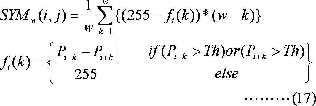
対称性評価部222は、特徴量抽出画像(エッジ画像)103に対して、上記(数式17)による処理を行う。(数式17)では、(w-k)により重み付けを行っている。つまり、特徴量抽出画像(エッジ画像)103上において、注目画素に近い位置に存在する領域ほど、強い重み付けがなされる。その結果、注目画素に近い領域であって、かつ、左右対称性の高い領域において、対称性評価値SYMw(i、j)は、大きな値となる。
また、対称性評価部222は、特徴量抽出画像(エッジ画像)103に対して、下記(数式18)による処理を行ってもよい。(数式18)では、k≧a0(a0は、a0≦wを満たす所定の値)の区間において単調減少となる関数c(k)により重み付けを行っている。つまり、特徴量抽出画像(エッジ画像)103上において、注目画素に近い位置に存在する領域ほど、強い重み付けがなされる。その結果、注目画素に近い領域であって、かつ、左右対称性の高い領域において、対称性評価値SYMw(i、j)は、大きな値となる。

ここで、図14を用いて、(数式18)に相当する処理について、説明する。図14は、特徴量抽出画像の一例を模式的に示す図であり、白い部分の領域に含まれる画素は、その画素値(画像特徴量)が取り得る最大値(例えば、「255」(8ビットデータ))であり、黒い部分に含まれる画素は、その画素値(画像特徴量)が取り得る最小値(例えば、「0」(8ビットデータ))であるものとする。また、(数式18)の値a0は、図14に示すように(図14に示した)w1より若干大きな値をとるものとする。
注目画素の水平方向の位置(i座標)が軸C2上である場合、図14(a)に示すように、領域R2の水平方向の幅w1のとき、対称性評価値SYMw(i、j)は最大値をとる。つまり、領域BCが軸C2付近において左右対称性が高いため、領域BCでのc(k)による重み付けが大きいため、図14(a)に示す領域R2の水平方向の幅w1がwa(対称性評価値SYMw(i、j)が最大値をとるときの対称幅w)となる。
一方、図14(b)に示すように、領域R2の水平方向の幅がw2のとき、wがa0より大きい領域についての重み付けc(k)は、wについて単調減少となるため、領域BLおよびBRについての重み付けc(k)の値は、小さな値となる。したがって、領域R2の水平方向の幅がw2のとき、対称性評価値SYMw(i、j)は、水平方向の幅w1のときの対称性評価値SYMw(i、j)よりも小さな値となる。
このように、本変形例の物体検出システムの対称性評価部222は、(数式18)に相当する処理を行い、対称性評価値SYMw(i、j)を取得するとともに、対称性評価値SYMw(i、j)が最大となるときの対称幅waを取得する。
なお、対称軸(中心軸)近傍において、左右対称領域を検出する場合、対称性評価値SYMw(i、j)の最大値をとるwが複数存在する場合、最大のwをwaとするようにしてもよい。例えば、対称軸(中心軸)近傍において、対称性評価値SYMw(i、j)の最大値をとるwが連続している場合、wの値が最大であるときの対称幅が、対称軸近傍に存在する対称性の高い物体の幅と近い値である可能性が高いと考えられる。したがって、対称軸(中心軸)近傍において、左右対称領域を検出する場合、対称性評価値SYMw(i、j)の最大値をとるwが複数存在する場合、最大のwをwaとすればよい。
そして、中心検出部223および物体領域検出部224において、第5実施形態と同様の処理を行うことで、対称軸近傍において左右対称性の高い物体(領域)を、適切に検出することができる。例えば、特徴量抽出画像が図15に示す画像である場合、本変形例の物体検出システムにより、対称軸近傍において左右対称性の高い物体(領域)BCを、検出領域DA1として、適切に検出することができる。
なお、画像上の距離による重み付け関数c(k)は、上記(数式18)で示した関数に限定されることはなく、任意の関数に設定してもよい。
例えば、画像上の距離による重み付け関数c(k)を、図16(a)、(b)に示すように単調減少関数(一部kについてc(k)が一定値をとる区間がある場合等を含む。)としてもよい。重み付け関数c(k)を単調減少関数に設定した場合、対称軸付近に高い対称性を有する物体を検出することができる。なお、図16(a)は、本変形例の(数式18)の処理に対応する。
一方、画像上の距離による重み付け関数c(k)を、図16(c)、(d)に示すように単調増加関数(一部kについてc(k)が一定値をとる区間がある場合等を含む。)としてもよい。重み付け関数c(k)を単調増加関数に設定した場合、対称軸から離れた領域に高い対称性を有する物体を検出することができる。なお、図16(a)は、第5実施形態の(数式14)の処理(c(k)=kとした場合の処理)に対応する。
なお、画像上の距離による重み付け関数c(k)は、上記に限定されるものではなく、例えば、指数関数、シグモイド関数等を用いた関数や、折れ線による関数等により、画像上の距離による重み付け関数c(k)を設定してもよい。
以上のように、本変形例の物体検出システムでは、画像上の距離による重み付け関数c(k)を、単調減少関数(一部単調でない部分を含んでもよい)に設定することで、対称軸付近の対称性の高い物体を適切に検出することができる。
[第6実施形態]
次に、第6実施形態について、説明する。
次に、第6実施形態について、説明する。
本実施形態の物体検出システムの構成は、第5実施形態と同様である。以下では、本実施形態において、第5実施形態と相違する点について、説明する。なお、上記実施形態と同様の部分については、上記実施形態と同様の部分については、同一符号を付し、詳細な説明を省略する。
第5実施形態では、画像特徴量抽出部221は、物体の画像特徴量としてエッジ成分を利用した。そして、画像特徴量として抽出したエッジ成分に基づき、対称性の評価を行った。
第6実施形態では、画像特徴量抽出部221は、物体の画像特徴量として特定の色成分を利用する。たとえば、画像特徴量抽出部221は、画像特徴量として赤色成分を抽出する。
以下、本実施形態の物体検出システムの動作について、説明する。
図17Aは、本実施形態の物体検出システムにおいて実行される物体検出処理の各段階において取得される画像の一例を示した図である。
なお、本実施形態においても、撮像装置1において、図10Aに示した撮像画像101が取得され、撮像画像101が物体検出装置2で処理される場合を例に説明する。
画像入力部21Aは、撮像装置1から入力されたRGB色空間の画像信号(R成分信号、G成分信号およびB成分信号)を、YCbCr色空間の信号(Y成分信号、Cb成分信号およびCr成分信号)に変換する。そして、画像入力部21Aは、Cr成分信号(Cr成分画像202)を画像特徴量抽出部221に出力する。
画像特徴量抽出部221は、画像入力部21Aにより取得されたCr成分画像(色差赤色成分画像)202に対して、画像特徴量を抽出する処理を実行する。なお、本実施形態では、画像特徴量として、Cr成分に相関のある物理量を利用する。
つまり、本実施形態では、画像特徴量抽出部221は、Cr成分画像202に対してCr成分強調処理(エンハンス処理)を実行し、特徴量抽出画像(R成分画像(Cr成分強調画像))203を生成する。
この後の処理は第5実施形態と同様である。第5実施形態におけるエッジ画像をR成分画像に置き換えた上で、同様の処理を実行し、対称性のある物体を検出する。
つまり、対称性評価部222は、第5実施形態と同様の処理を、図17Cに示す特徴量抽出画像(R成分画像(Cr成分強調画像))203に対して実行し、対称性評価マップデータ(図17Dに示す対称性評価マップ画像204に対応。)および対称幅マップデータ(図17Eに示す対称幅マップ画像205に対応。)を取得する。
そして、中心検出部223は、第5実施形態と同様の処理を、対称性評価マップデータ(図17Dに示す対称性評価マップ画像204に対応。)に対して実行し、対称中心マップデータ(図17Fに示す対称中心マップ画像206に対応。)を取得する。
物体領域検出部224は、第5実施形態と同様の処理を、対称中心マップデータ(図17Fに示す対称中心マップ画像206に対応。)および対称幅マップデータ(対称幅マップ画像205)を利用して、物体の水平方向の幅を検出し、さらに、物体の垂直方向の幅を検出する。
合成部23Aは、第5実施形態と同様に、物体領域検出部224から出力される検出した対称性の高い物体の画像上の領域を特定する情報に基づいて、画像入力部21Aから出力される画像(入力画像101)上に、対称性の高い物体に相当する画像領域を明示する画像を生成(合成)する。
そして、合成部23Aにより生成(合成)された画像は、表示装置3により表示される。図17Gに合成部23Aにより取得された画像(出力画像207)の一例を示す。図17Gに示すように、左右対称の位置に赤色の画像領域(画像領域230)を有する領域が適切に検出されている。
図17Gは、第6実施形態において表示装置3に表示された合成画像207を示す図である。第5実施形態においては、エッジ成分により物体の対称性を評価したので、車両の全体が物体の大きさとして抽出されている。これに対して、第6実施形態においては、車両のテールランプの赤色を中心に物体の対称性が評価されたので、テールランプを含む領域(画像領域230)が抽出されていることが分かる。
以上のように、本実施形態の物体検出システムでは、入力画像(撮像画像)の画像特徴量を抽出した画像(特定の色成分を抽出した画像)に対して、所定の方向(水平方向)についての対称性を評価するために、幅(所定方向(水平方向)の幅)を変化させながら対称性の評価を行う。したがって、本実施形態の物体検出システムでは、所定の画像領域の対称性が高いと判定した場合、対称性が高いと判定した画像領域の所定方向(水平方向)の幅も同時に取得することができる。つまり、本実施形態の物体検出システムでは、画像に含まれる物体の対称性を利用して、物体の位置と大きさを同時に抽出することが可能である。
また、本実施形態の物体検出システムでは、所定の方向(水平方向)についての対称性の評価データを用いて、対称性の高い物体の中心軸を検出することができる。したがって、本実施形態の物体検出システムでは、少ない演算量で、精度良く、対称性の高い物体の検出を行うことができる。さらに、本実施形態の物体検出システムでは、特定の色成分について抽出した画像を用いて処理を行うので、特定の色成分を多く含む対称性の高い物体を精度良く検出することができる。
さらに、本実施形態の物体検出システムでは、注目画素(物体の中心軸(対称軸))からの距離による重み付けを行った対称性評価値を取得し、当該対称性評価値を用いた処理を行うので、中心軸(対称軸)から離れた位置に存在する、特定の色成分についての対称性の高い物体を精度よく検出することができる。
なお、第5実施形態と第6実施形態の両方を組み合わせてもよい。エッジ画像に対して物体の垂直方向および水平方向の幅および位置を特定する。さらに、特定の色成分画像を利用して物体の垂直方向および水平方向の幅および位置を特定する。そして、それらの平均値をとることで物体の位置および大きさを特定することができる。あるいは、エッジ画像に基づいて求められた値と色成分に基づいて求められた値のいずれかに重みづけを行って物体の位置および大きさを特定してもよい。
また、上記では、赤色成分に注目して処理を行う場合について説明したが、これに限定されることはなく、他の色成分(例えば、緑色成分や青色成分)に注目して処理を行い、所定の色についての対称性の高い物体を検出するようにしてもよい。
また、画像特徴量を抽出するための色空間変換は、本実施形態で説明したものに限定されることはなく、特定の色成分の信号を抽出するために、他の色空間変換を行い、所望の色成分信号(色成分画像)を抽出するようにしてもよい。
≪第1変形例≫
次に、本実施形態の第1変形例について説明する。
次に、本実施形態の第1変形例について説明する。
本変形例の物体検出システムおよび物体検出装置は、第5実施形態の物体検出システムおよび物体検出装置と、それぞれ、同様の構成を有している。
本変形例の物体検出装置では、第5実施形態の変形例と同様に、対称性評価部222は、(数式14)の代わりに、(数式17)または(数式18)による処理を行う。本変形例の物体検出装置では、第6実施形態と同様に、画像特徴量抽出部221は、物体の画像特徴量として特定の色成分を利用する。たとえば、画像特徴量抽出部221は、画像特徴量として赤色成分を抽出する。
ここで、本変形例の物体検出システムにおいて、図18に示す画像が入力された場合について、説明する。
図18(a)は、オートバイを背後から撮像した画像301である。撮像画像(入力画像)301において、オートバイのテールランプ311は、赤色であるものとする。
図18(a)に示す画像が本変形例の物体検出装置に入力された場合、物体検出部22Aの画像特徴量抽出部221は、図18(b)に示す特徴量抽出画像(R成分(Cr成分)抽出画像)302を取得する。図18(b)に示した特徴量抽出画像(R成分(Cr成分)抽出画像)302において、オートバイのテールランプ311に相当する領域は、軸C3近傍に存在しており、かつ、オートバイのテールランプ311に相当する領域の画素の画素値(画像特徴量(赤色成分量))が大きい。このため、対称性評価部222により算出される対称性評価値SYMw(i、j)は、注目画素の水平方向の位置(i座標)が対称軸付近である場合に、最大値をとることとなる。そして、そのときの対称幅が図18(b)に示したw3となる。つまり、wa(対称性評価値SYMw(i、j)が最大値をとるときの対称幅w)がw3となる。
そして、本変形例の中心検出部223および物体領域検出部224において、前述の実施形態と同様に、処理が実行されることで、図18(c)に示す出力画像が取得される。図18(c)の出力画像では、赤色で、かつ、対称軸近傍における左右対称性が高い領域(物体)(オートバイのテールランプ部分)が、適切に検出されている。
以上のように、本変形例の物体検出システムでは、対称性評価部222により、(数式17)または(数式18)による処理が実行されることで、特定の色成分(本変形例では赤色成分)の対称軸近傍において対称性が高い領域(物体)を適切に検出することができる。
なお、第5実施形態の変形例で説明したのと同様に、本変形例においても、画像上の距離による重み付け関数c(k)は、(数式18)で示した関数に限定されることはなく、任意の関数(例えば、図16に示したグラフに相当する関数)に設定されるものであってもよい。
[第7実施形態]
次に、第7実施形態について、説明する。
次に、第7実施形態について、説明する。
本実施形態の物体検出システムの構成は、第5実施形態と同様である。以下では、本実施形態において、第5実施形態と相違する点について、説明する。なお、上記実施形態と同様の部分については、上記実施形態と同様の部分については、同一符号を付し、詳細な説明を省略する。
本実施形態の対称性評価部222は、(数式14)の代わりに、下記(数式19)に相当する処理を実行する。

前述の実施形態と同様に、(数式19)において、SYMw(i、j)は、対称性の評価値を示す。(数式19)において、kは、1~wまでの値をとる整数である。
画素Pi-kと画素Pi+kは、注目画素Piを中心として左右対称の位置にある画素である。画素Pi-kと画素Pi+kの画素値が等しいとき、その差分|Pi-k-Pi+k|は最小値0となる。このとき、(255-|Pi-k-Pi+k|)は、最大値255となる。
そして、(255-|Pi-k-Pi+k|)は、Pi-kおよびPi+kを乗算されることで、注目画素Piから左右にk画素離れた画素の画像特徴量で重み付けされる。これにより、画像特徴量が小さい画素を対称性の評価から除外することができる。つまり、例えば、特徴量抽出画像をエッジ画像103としたとき、エッジ画像103において、エッジではない部分のPi-kおよびPi+kは、「0」に近い値をとるので、エッジでない部分では、(255-|Pi-k-Pi+k|)×Pi-k×Pi+kは、「0」に近い値をとることになる。
つまり、(数式19)においては、注目している画像特徴量(例えば、エッジ成分量や特定の色成分量(例えば、赤色成分量))についての対称性が高いほどSYMw(i、j)は、大きな値をとる。
本実施形態の対称性評価部222は、前述の実施形態と同様に、(数式15)に相当する処理を行い、最大値maxSYMを与えるwを、対称幅waとして取得する。
そして、本実施形態の中心検出部223、物体領域検出部224、および、合成部23Aは、前述と同様の処理を行う。
このように、本実施形態の物体検出システムでは、入力画像(撮像画像)の画像特徴量を抽出した画像に対して、所定の方向(水平方向)についての対称性を評価するために、幅(所定方向(水平方向)の幅)を変化させながら対称性の評価を行う。したがって、本実施形態の物体検出システムでは、所定の画像領域の対称性が高いと判定した場合、対称性が高いと判定した画像領域の所定方向(水平方向)の幅も同時に取得することができる。つまり、本実施形態の物体検出システムでは、画像に含まれる物体の対称性を利用して、物体の位置と大きさを同時に抽出することが可能である。
また、本実施形態の物体検出システムでは、所定の方向(水平方向)についての対称性の評価データを用いて、対称性の高い物体の中心軸を検出することができる。したがって、本実施形態の物体検出システムでは、少ない演算量で、精度良く、対称性の高い物体の検出を行うことができる。
なお、本実施形態の物体検出システムにおいて、画像特徴量抽出部221は、例えば、画像特徴量をエッジ成分として、入力画像のエッジ成分を抽出したエッジ画像を取得するものであってもよい。この場合、本実施形態の物体検出システムでは、図9と同様の処理結果(類似の処理結果)を取得することができる。
また、本実施形態の物体検出システムにおいて、画像特徴量抽出部221は、例えば、画像特徴量を特定の色成分(例えば、赤色成分(R成分やCr成分等))として、入力画像の特定の色成分を抽出した画像(例えば、赤色成分画像(R成分画像やCr成分画像等))を取得するものであってもよい。この場合、本実施形態の物体検出システムでは、図17Aと同様の処理結果(類似の処理結果)を取得することができる。
[第8実施形態]
次に、第8実施形態について、説明する。
次に、第8実施形態について、説明する。
本実施形態の物体検出システムの構成は、前述の実施形態と同様である。以下では、本実施形態において、前述の実施形態と相違する点について、説明する。なお、前述の実施形態と同様の部分については、同一符号を付し、詳細な説明を省略する。
本実施形態の対称性評価部222は、(数式14)の代わりに、下記(数式20)に相当する処理を実行する。

画素Pi-kと画素Pi+kは、注目画素Piを中心として左右対称の位置にある画素である。画素Pi-kと画素Pi+kの画素値が等しいとき、その差分|Pi-k-Pi+k|は最小値0となる。このとき、(255-|Pi-k-Pi+k|)は、最大値255となる。
そして、(255-|Pi-k-Pi+k|)は、Pi-kおよびPi+kを乗算されることで、注目画素Piから左右にk画素離れた画素の画像特徴量で重み付けされる。これにより、画像特徴量が小さい画素を対称性の評価から除外することができる。つまり、例えば、特徴量抽出画像をエッジ画像103としたとき、エッジ画像103において、エッジではない部分のPi-kおよびPi+kは、「0」に近い値をとるので、エッジでない部分では、(255-|Pi-k-Pi+k|)×Pi-k×Pi+kは、「0」に近い値をとることになる。
つまり、(数式20)においては、注目している画像特徴量(例えば、エッジ成分量や特定の色成分量(例えば、赤色成分量))についての対称性が高いほどSYMw(i、j)は、大きな値をとる。
さらに、(数式20)では、注目画素(i,j)からの距離k(注目画素(i,j)から画素(i,j+k)(または画素(i,j-k))までの画素数(画像上の距離に相当))を乗ずることで、水平方向の位置情報(注目画素からの距離情報)による重み付けを行う。つまり、注目画素から水平方向に離れる程、対称性の評価についての重み付けが大きくなる。したがって、注目画素を中心として、注目画素から左右に離れた領域に高い(左右)対称性(注目している画像特徴量(本実施形態ではエッジ成分量)についての対称性)を有する領域がある場合、対称性評価値SYMw(i、j)が大きな値となる。
つまり、対称性評価部222は、(数式20)による処理を実行することで、画像特徴量(Pi-kおよびPi+k)および水平方向の位置情報(注目画素からの距離情報)による重み付けを行った対称性評価値SYMw(i、j)を取得することができる。
本実施形態の対称性評価部222は、前述の実施形態と同様に、(数式20)に相当する処理を行い、最大値maxSYMを与えるwを、対称幅waとして取得する。
そして、本実施形態の中心検出部223、物体領域検出部224、および、合成部23は、前述と同様の処理を行う。
このように、本実施形態の物体検出システムでは、入力画像(撮像画像)の画像特徴量を抽出した画像に対して、所定の方向(水平方向)についての対称性を評価するために、幅(所定方向(水平方向)の幅)を変化させながら対称性の評価を行う。したがって、本実施形態の物体検出システムでは、所定の画像領域の対称性が高いと判定した場合、対称性が高いと判定した画像領域の所定方向(水平方向)の幅も同時に取得することができる。つまり、本実施形態の物体検出システムでは、画像に含まれる物体の対称性を利用して、物体の位置と大きさを同時に抽出することが可能である。
また、本実施形態の物体検出システムでは、所定の方向(水平方向)についての対称性の評価データを用いて、対称性の高い物体の中心軸を検出することができる。したがって、本実施形態の物体検出システムでは、少ない演算量で、精度良く、対称性の高い物体の検出を行うことができる。
さらに、本実施形態の物体検出システムでは、注目画素(物体の中心軸(対称軸))からの距離による重み付けを行った対称性評価値を取得し、当該対称性評価値を用いた処理を行うので、中心軸(対称軸)から離れた位置に存在する対称性の高い物体を精度よく検出することができる。
なお、本実施形態の物体検出システムにおいて、画像特徴量抽出部221は、例えば、画像特徴量をエッジ成分として、入力画像のエッジ成分を抽出したエッジ画像を取得するものであってもよい。この場合、本実施形態の物体検出システムでは、図9と同様の処理結果(類似の処理結果)を取得することができる。
また、本実施形態の物体検出システムにおいて、画像特徴量抽出部221は、例えば、画像特徴量を特定の色成分(例えば、赤色成分(R成分やCr成分等))として、入力画像の特定の色成分を抽出した画像(例えば、赤色成分画像(R成分画像やCr成分画像等))を取得するものであってもよい。この場合、本実施形態の物体検出システムでは、図17Aと同様の処理結果(類似の処理結果)を取得することができる。
≪第1変形例≫
次に、第8実施形態の第1変形例について、説明する。
次に、第8実施形態の第1変形例について、説明する。
本変形の物体検出システムの構成は、前述の実施形態と同様である。以下では、本実施形態において、前述の実施形態と相違する点について、説明する。なお、前述の実施形態と同様の部分については、同一符号を付し、詳細な説明を省略する。
本変形例の対称性評価部222は、(数式20)の代わりに、下記(数式21)に相当する処理を実行する。つまり、(数式20)では、画素位置(距離)についての重み付けがkであったが、(数式21)では、画素位置(距離)についての重み付けが、kについての任意の関数c(k)となっている。

例えば、中心軸(対称軸)付近に高い対称性を有する領域を検出したい場合、
c(k)=w-k
または、下記(数式22)に設定すればよい。
c(k)=w-k
または、下記(数式22)に設定すればよい。

以上のように、本変形例の物体検出システムでは、対称性評価部222により、(数式21)による処理が実行されることで、所定の領域(対称軸から所定の距離だけ離れた領域)において、対称性が高い領域(物体)を適切に検出することができる。
なお、第5実施形態の変形例で説明したのと同様に、本変形例においても、画像上の距離による重み付け関数c(k)は、上記で示した関数に限定されることはなく、任意の関数(例えば、図16に示したグラフに相当する関数)に設定されるものであってもよい。
[第9実施形態]
次に、第9実施形態について、説明する。
次に、第9実施形態について、説明する。
本実施形態の物体検出システムの構成は、前述の実施形態と同様である。以下では、本実施形態において、前述の実施形態と相違する点について、説明する。なお、前述の実施形態と同様の部分については、同一符号を付し、詳細な説明を省略する。
本実施形態の対称性評価部222は、(数式21)の代わりに、下記(数式23)に相当する処理を実行する。つまり、(数式21)では、対称性評価値を算出するための画像上の領域が水平ライン1ライン分からなる領域であった。それに対して、(数式23)では、対称性評価値を算出するための画像上の領域が水平ライン(2n+1)ライン分(注目画素が存在する水平ラインを中心とした(2n+1)個の水平ライン)(nは自然数)からなる領域である。
つまり、本実施形態の対称性評価部222は、(数式23)により、(2n+1)個の水平ラインについて、それぞれ、対称性評価値を算出し、算出した各水平ラインの対称性評価値を積算し、積算した値を水平ライン数で除算することで、平均値を取得する。そして、対称性評価部222は、取得した平均値を、注目画素(i,j)の対称性評価値SYMw(i、j)とする。

例えば、画像上において、中心軸(対称軸)から離れた位置に存在する、対称性の高い領域を検出する場合、
c(k)=k
と設定すればよい。なお、関数c(k)を、図16(d)に示すような関数に設定してもよい。
c(k)=k
と設定すればよい。なお、関数c(k)を、図16(d)に示すような関数に設定してもよい。
また、例えば、画像上において、中心軸(対称軸)近傍に存在する、対称性の高い領域を検出する場合、
c(k)=w-k
と設定すればよい。なお、関数c(k)を、図16(a)、(b)に示すような関数に設定してもよい。
c(k)=w-k
と設定すればよい。なお、関数c(k)を、図16(a)、(b)に示すような関数に設定してもよい。
なお、対称性評価部222は、(数式23)に示すように、対称性評価値を算出する対象領域の垂直方向の幅を、注目画素が含まれる水平ライン、注目画素が含まれる水平ラインの上に位置するnラインおよび下に位置するnラインの合計(2n+1)ライン分に相当する幅として、対称性評価値を算出するが、注目画素が画像上端付近または下端付近であり、かつ、注目画素が含まれる水平ラインの上下にnライン分ずつ確保できない場合、対称性評価値を算出する対象領域の垂直方向の幅を変化させてもよい。例えば、注目画素が画像上端付近であり、注目画素が含まれる水平ラインの上に、(画像上端まで)n1ライン分(n1<nとする)存在している場合、(j-n1)ラインから(j+n)ラインまでの合計(n1+n+1)ライン分の領域を、対称性評価値を算出する対象領域としてもよい。
本実施形態の対称性評価部222は、前述の実施形態と同様に、(数式23)に相当する処理を行い、最大値maxSYMを与えるwを、対称幅waとして取得する。
そして、本実施形態の中心検出部223、物体領域検出部224、および、合成部23は、前述と同様の処理を行う。
このように、本実施形態の物体検出システムでは、本実施形態の対称性評価部222は、(数式23)により、(2n+1)個の水平ラインについて、それぞれ、対称性評価値を算出し、算出した各水平ラインの対称性評価値を積算し、積算した値を水平ライン数で除算することで取得した平均値により、注目画素(i,j)の対称性評価値SYMw(i、j)を算出する。つまり、本実施形態の物体検出システムでは、垂直方向に所定の幅を有する画像領域を対称性評価の対象とするので、垂直方向に高い相関性を有する対称領域(例えば、対称軸(中心軸)と平行な辺を有する四角形の物体等)を精度良く検出することができる。
なお、対称性評価部222は、(数式23)の代わりに、(数式24)を用いて、対称性評価値SYMw(i、j)を算出してもよい。なお、c(k)については、(数式23)と同様である。

一方、(数式24)の処理では、対称性評価部222は、まず、各項の垂直方向の積算処理(平均値算出処理)を行い、次に、水平方向において対称性評価を行うことで、注目画素(i,j)の対称性評価値SYMw(i、j)を算出する。
対称性評価部222が(数式24)による処理を行うことで、(数式23)の処理と同様の処理結果を取得することができる。
≪第1変形例≫
次に、第9実施形態の第1変形例について、説明する。
次に、第9実施形態の第1変形例について、説明する。
本変形の物体検出システムの構成は、前述の実施形態と同様である。以下では、本実施形態において、前述の実施形態と相違する点について、説明する。なお、前述の実施形態と同様の部分については、同一符号を付し、詳細な説明を省略する。
本変形例の対称性評価部222は、(数式23)の代わりに、下記(数式25)に相当する処理を実行する。つまり、(数式23)では、垂直方向の重み付けが、全ての水平ラインにおいて、「1」(重み付けなし)であったが、(数式25)では、垂直方向の重み付け関数d(m)により、水平ラインごとに、関数d(m)で決定される重み付け処理がなされる。なお、c(k)については、(数式23)と同様である。

例えば、
d(m)=n+1-|m-j|
や
d(m)=c1×exp(-c2×(m-j)^2)
(c1は、d(m)の最大値を決定するための係数。c2は垂直方向のレンジ調整用の係数。)
とすることで、注目画素(i,j)が存在する水平ラインでの重み付けを大きくし、注目画素(i,j)が存在する水平ラインから離れる程、重み付けを小さくすることができる。
これにより、注目画素(i,j)が存在する水平ライン付近において、左右対称性が高い領域が存在する場合に、対称性評価値が高くなるようにすることができる。
なお、対称性評価部222は、(数式21)の代わりに、(数式26)を用いて、対称性評価値SYMw(i、j)を算出してもよい。なお、c(k)については、(数式21)と同様である。

一方、(数式26)の処理では、対称性評価部222は、まず、各項の垂直方向の積算処理(平均値算出処理)を行い、次に、水平方向において対称性評価を行うことで、注目画素(i,j)の対称性評価値SYMw(i、j)を算出する。
対称性評価部222が(数式26)による処理を行うことで、(数式25)の処理と同様の処理結果を取得することができる。
[他の実施形態]
上述の実施形態および変形例の一部または全部を組み合わせてもよい。
上述の実施形態および変形例の一部または全部を組み合わせてもよい。
上述の実施形態においては、水平方向に関して対称性を有する物体を検出した。同様に、垂直方向に関して対称性を有する物体を検出してもよい。つまり、上述の実施形態における水平方向の処理と垂直方向の処理を逆にして、上述の実施形態の処理を実行することで、垂直方向に関して対称性を有する物体を検出してもよい。
また、上述の実施形態の物体検出装置2において、各機能部の全部または一部が、共有のメモリ(例えば、フレームメモリ)を用いて、処理を行うようにしてもよい。
また、上述の実施形態の物体検出システムにおいて、撮像装置が、所定のフレームレート(例えば、15fps)でカラー画像を撮像する場合であれば、上記共有のメモリは、物体検出装置が当該所定のフレームレート(例えば、15fps)のカラー画像を処理できるだけのメモリ容量を有するメモリとすることが好ましい。
また、上述の実施形態において、8ビットのデータ(0~255のデータ)を前提として処理(数式で示した処理等)を行っている部分があるが、ビット数が、上記で説明したビット数(データの取り得る範囲)に限定されないのは言うまでもない。また、上述の実施形態において、データを所定の範囲のデータとするために、レンジ変換処理や、正規化処理や、所定の閾値によるクリップ処理等を行うようにしてもよい。
また、上記実施形態で説明した物体検出システム又は物体検出装置において、各ブロックは、LSIなどの半導体装置(集積回路やプログラム可能なFPGA(Field Programmable Gate Array)等を含む。)により個別に1チップ化されても良いし、一部又は全部を含むように1チップ化されても良い。また、上記実施形態で説明した物体検出システム又は物体検出装置において、各ブロックは、複数のチップ(LSIなどの半導体装置)により実現されるものであってもよい。
また、上記各実施形態の各機能ブロックの処理の一部または全部は、プログラムにより実現されるものであってもよい。そして、上記各実施形態の各機能ブロックの処理の一部または全部は、コンピュータにおいて、中央演算装置(CPU)により行われる。また、それぞれの処理を行うためのプログラムは、ハードディスク、ROMなどの記憶装置に格納されており、ROMにおいて、あるいはRAMに読み出されて実行される。
また、上記実施形態の各処理をハードウェアにより実現してもよいし、ソフトウェア(OS(オペレーティングシステム)、ミドルウェア、あるいは、所定のライブラリとともに実現される場合を含む。)により実現してもよい。さらに、ソフトウェアおよびハードウェアの混在処理により実現しても良い。なお、上記実施形態に係る物体検出システム又は物体検出装置をハードウェアにより実現する場合、各処理を行うためのタイミング調整を行う必要があるのは言うまでもない。上記実施形態においては、説明便宜のため、実際のハードウェア設計で生じる各種信号のタイミング調整の詳細については省略している。
また、上記実施形態における処理方法の実行順序は、必ずしも、上記実施形態の記載に制限されるものではなく、発明の要旨を逸脱しない範囲で、実行順序を入れ替えることができるものである。
前述した方法をコンピュータに実行させるコンピュータプログラム及びそのプログラムを記録したコンピュータ読み取り可能な記録媒体は、本発明の範囲に含まれる。ここで、コンピュータ読み取り可能な記録媒体としては、例えば、フレキシブルディスク、ハードディスク、CD-ROM、MO、DVD、DVD-ROM、DVD-RAM、BD(Blu-ray Disc(登録商標))、半導体メモリを挙げることができる。
上記コンピュータプログラムは、上記記録媒体に記録されたものに限られず、電気通信回線、無線又は有線通信回線、インターネットを代表とするネットワーク等を経由して伝送されるものであってもよい。
なお、本発明の具体的な構成は、前述の実施形態に限られるものではなく、発明の要旨を逸脱しない範囲で種々の変更および修正が可能である。
[付記]
また、本発明は、以下のようにも表現することができる。
(付記1)
画像を入力する画像入力部と、
前記画像に含まれる複数の評価画素について、各評価画素周辺の画素の特徴量に基づき、各評価画素周辺の第1の方向に関する対称性を評価する対称性評価部と、
前記複数の評価画素について前記第1の方向に関する対称幅を算出する対称幅検出部と、
前記複数の評価画素の中で対称性が所定の基準を上回る画素を対称中心画素として検出する中心検出部と、
前記対称中心画素の前記対称幅に基づいて前記画像に含まれる対称性を有する物体の前記第1の方向に関する物体幅を検出し、前記対称中心画素の前記第1の方向と直交する第2の方向に関する分布に基づいて前記物体の前記第2の方向に関する物体幅を検出する物体幅検出部と、
を備える物体検出装置。
[付記]
また、本発明は、以下のようにも表現することができる。
(付記1)
画像を入力する画像入力部と、
前記画像に含まれる複数の評価画素について、各評価画素周辺の画素の特徴量に基づき、各評価画素周辺の第1の方向に関する対称性を評価する対称性評価部と、
前記複数の評価画素について前記第1の方向に関する対称幅を算出する対称幅検出部と、
前記複数の評価画素の中で対称性が所定の基準を上回る画素を対称中心画素として検出する中心検出部と、
前記対称中心画素の前記対称幅に基づいて前記画像に含まれる対称性を有する物体の前記第1の方向に関する物体幅を検出し、前記対称中心画素の前記第1の方向と直交する第2の方向に関する分布に基づいて前記物体の前記第2の方向に関する物体幅を検出する物体幅検出部と、
を備える物体検出装置。
(付記2)
付記1に記載の物体検出装置において、
前記中心検出部は、前記第1の方向に関する対称性の変化に極大を与える点を前記対称中心画素として検出する物体検出装置。
付記1に記載の物体検出装置において、
前記中心検出部は、前記第1の方向に関する対称性の変化に極大を与える点を前記対称中心画素として検出する物体検出装置。
(付記3)
付記1または付記2に記載の物体検出装置であって、
前記対称性評価部は、各評価画素周辺の画素の特徴量の近似性に基づき対称性を評価する物体検出装置。
付記1または付記2に記載の物体検出装置であって、
前記対称性評価部は、各評価画素周辺の画素の特徴量の近似性に基づき対称性を評価する物体検出装置。
(付記4)
付記1ないし付記3のいずれかに記載の物体検出装置であって、
前記対称幅検出部は、各評価画素について、対称性が最も高くなる幅を、前記対称幅として検出する物体検出装置。
付記1ないし付記3のいずれかに記載の物体検出装置であって、
前記対称幅検出部は、各評価画素について、対称性が最も高くなる幅を、前記対称幅として検出する物体検出装置。
(付記5)
付記1ないし付記4のいずれかに記載の物体検出装置であって、
前記物体幅検出部は、
前記対称中心画素の前記対称幅の最大値あるいは平均値を前記第1の方向に関する物体幅として検出する物体検出装置。
付記1ないし付記4のいずれかに記載の物体検出装置であって、
前記物体幅検出部は、
前記対称中心画素の前記対称幅の最大値あるいは平均値を前記第1の方向に関する物体幅として検出する物体検出装置。
(付記6)
付記1ないし付記4のいずれかに記載の物体検出装置であって、
前記物体幅検出部は、前記対称中心画素の各対称幅を前記第1の方向に関する物体幅として検出する物体検出装置。
付記1ないし付記4のいずれかに記載の物体検出装置であって、
前記物体幅検出部は、前記対称中心画素の各対称幅を前記第1の方向に関する物体幅として検出する物体検出装置。
(付記7)
付記1ないし付記6のいずれかに記載の物体検出装置であって、
前記物体幅検出部は、前記第2の方向に関して連続して配置された前記対称中心画素の一端および他端を、前記第2の方向に関する物体幅の一端および他端として検出する物体検出装置。
付記1ないし付記6のいずれかに記載の物体検出装置であって、
前記物体幅検出部は、前記第2の方向に関して連続して配置された前記対称中心画素の一端および他端を、前記第2の方向に関する物体幅の一端および他端として検出する物体検出装置。
(付記8)
付記1ないし付記7のいずれかに記載の物体検出装置であって、
前記対称性評価部は、画素の特徴量として画素のエッジ強度を用いる物体検出装置。
付記1ないし付記7のいずれかに記載の物体検出装置であって、
前記対称性評価部は、画素の特徴量として画素のエッジ強度を用いる物体検出装置。
(付記9)
付記1ないし付記7のいずれかに記載の物体検出装置であって、
前記対称性評価部は、画素の特徴量として画素の所定の色成分の強度を用いる物体検出装置。
付記1ないし付記7のいずれかに記載の物体検出装置であって、
前記対称性評価部は、画素の特徴量として画素の所定の色成分の強度を用いる物体検出装置。
(付記10)
付記1ないし付記9のいずれかに記載の物体検出装置であって、
前記対称性評価部は、前記第1の方向を水平方向とする対称性および前記第1の方向を垂直方向とする対称性を評価することにより、水平方向にのみ対称性を有する画素を特定し、
前記中心検出部は、前記複数の評価画素の中で対称性が所定の基準を上回る画素であって、水平方向にのみ対称性を有する画素を対称中心画素として検出する物体検出装置。
付記1ないし付記9のいずれかに記載の物体検出装置であって、
前記対称性評価部は、前記第1の方向を水平方向とする対称性および前記第1の方向を垂直方向とする対称性を評価することにより、水平方向にのみ対称性を有する画素を特定し、
前記中心検出部は、前記複数の評価画素の中で対称性が所定の基準を上回る画素であって、水平方向にのみ対称性を有する画素を対称中心画素として検出する物体検出装置。
(付記11)
付記1ないし付記10のいずれかに記載の物体検出装置であって、
前記対称性を有する物体として前記画像に含まれる車両を検出する物体検出装置。
付記1ないし付記10のいずれかに記載の物体検出装置であって、
前記対称性を有する物体として前記画像に含まれる車両を検出する物体検出装置。
1000 物体検出システム
1 撮像装置
2 物体検出装置
3 表示装置(モニタ)
21A 画像入力部
22A 物体検出部
23A 合成部
221 画像特徴量抽出部
222 対称性評価部
223 中心検出部
224 物体領域検出部
23A 合成部
1 撮像装置
2 物体検出装置
3 表示装置(モニタ)
21A 画像入力部
22A 物体検出部
23A 合成部
221 画像特徴量抽出部
222 対称性評価部
223 中心検出部
224 物体領域検出部
23A 合成部
Claims (35)
- 画像を入力する画像入力部と、
前記画像から所定の画像特徴量を抽出して特徴量抽出画像を生成する画像特徴量抽出部と、
前記特徴量抽出画像に対して、処理対象である注目画素ごとに、前記注目画素の周辺画素の画像特徴量に基づいて、前記注目画素の周辺の画像領域の第1方向に関する対称性を評価するとともに、前記第1方向に関する対称幅を算出する対称性評価部と、
前記注目画素について評価した対称性が所定の基準を上回る場合、当該注目画素を対称中心画素として検出する中心検出部と、
前記対称中心画素の前記対称幅に基づいて前記画像に含まれる対称性を有する物体の前記第1方向に関する物体幅を検出し、前記対称中心画素の前記第1方向と直交する第2方向に関する分布に基づいて前記物体の前記第2方向に関する物体幅を検出する物体領域検出部と、
を備える物体検出装置。 - 前記中心検出部は、前記第1方向に関する対称性の変化に極大を与える点を前記対称中心画素として検出する、
請求項1に記載の物体検出装置。 - 前記対称性評価部は、各注目画素の周辺の画素の画像特徴量の近似性に基づき対称性を評価する、
請求項1又は2に記載の物体検出装置。 - 前記対称性評価部は、各注目画素について、対称性が最も高くなる幅を、前記対称幅として検出する、
請求項1から3のいずれかに記載の物体検出装置。 - 前記物体領域検出部は、
前記対称中心画素の前記対称幅の最大値あるいは平均値を前記第1方向に関する物体幅として検出する、
請求項1から4のいずれかに記載の物体検出装置。 - 前記物体領域検出部は、前記対称中心画素の各対称幅を前記第1方向に関する物体幅として検出する、
請求項1から4のいずれかに記載の物体検出装置。 - 前記物体領域検出部は、前記第2方向に関して連続して配置された前記対称中心画素の一端および他端を、前記第2方向に関する物体幅の一端および他端として検出する、
請求項1から6のいずれかに記載の物体検出装置。 - 前記対称性評価部は、前記第1方向を水平方向とする対称性および前記第1方向を垂直方向とする対称性を評価することにより、水平方向にのみ対称性を有する画素を特定し、
前記中心検出部は、前記注目画素について評価した対称性が所定の基準を上回り、かつ、水平方向にのみ対称性を有すると判定された注目画素を対称中心画素として検出する、
請求項1から7のいずれかに記載の物体検出装置。 - 前記対称性を有する物体として前記画像に含まれる車両を検出する、
請求項1から8のいずれかに記載の物体検出装置。 - 対称性評価部は、
前記特徴量抽出画像に対して、処理対象である注目画素ごとに、前記画像上の第1方向についての対称性を評価するための領域である対称性評価領域を前記第1方向と直交する第2方向の中心軸を中心として対称となるように設定し、前記対称性評価領域の大きさを変化させながら、前記対称性評価領域に含まれ、前記中心軸について対称となる位置に存在する画素群の画像特徴量の相関値に対して、前記画素群の画像特徴量による重み付けを行った値を導出することで、前記第1方向の対称性の度合いを示す対称性評価値を取得する、
請求項1に記載の物体検出装置。 - 前記対称性評価部は、前記対称性評価値が第1方向についての対称性が最大であることを示す値である場合の前記対称性評価領域の大きさに基づいて、前記第1方向に関する対称幅を決定する、
請求項10に記載の物体検出装置。 - 前記対称性評価部は、
前記特徴量抽出画像上の画素値が0または正の値をとり、前記画像特徴量が大きい程、大きな値をとるものとし、前記特徴量抽出画像上の画素値の取り得る最大値以上の所定の値をPmaxとし、
前記特徴量抽出画像上の座標(i,j)の注目画素の画素値をPiとし、前記注目画素から前記第1方向の一方向である第1探索方向にk画素(kは自然数)離れた画素の画素値をPi-kとし、前記注目画素から前記第1方向の前記第1探索方向と逆方向である第2検索方向にk画素離れた画素の画素値をPi+kとし、
前記対称性評価領域の前記第1方向の幅を2w+1とするとき、
前記対称性評価領域の前記第1方向の幅2w+1(wは自然数)を変化させながら、
に基づいて、前記注目画素の前記対称性評価値を算出する、
請求項10または11に記載の物体検出装置。 - 前記対称性評価部は、
前記特徴量抽出画像上の画素値が0または正の値をとり、前記画像特徴量が大きい程、大きな値をとるものとし、前記特徴量抽出画像上の画素値の取り得る最大値以上の所定の値をPmaxとし、
前記特徴量抽出画像上の座標(i,j)の画素の画素値をPi,jとし、
前記対称性評価領域の前記第1方向の幅を2w+1とし、
前記対称性評価領域の前記第2方向の幅を2n+1とし、
所定の重み付け関数をd(m)とするとき、
前記対称性評価領域の前記第1方向の幅2w+1(wは自然数)を変化させながら、
または、
に基づいて、前記注目画素の前記対称性評価値を算出する、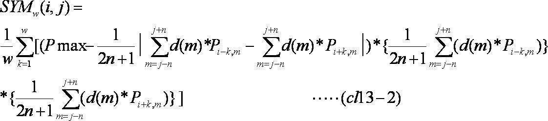
請求項10または11に記載の物体検出装置。 - 前記重み付け関数d(m)は、
(1)d(m)=1、
(2)d(m)=n+1-|m-j|、および
(3)d(m)=c1×exp(-c2×(m-j)^2)
(c1およびc2は、所定の正の係数)
のいずれか一つである、
請求項13に記載の物体検出装置。 - 前記対称性評価部は、
前記SYMw(i、j)の最大値maxSYMを取得するとともに、前記SYMw(i、j)が最大値となるときの前記対称性評価領域の前記第1方向の幅2w+1に基づいて、前記対称幅を決定する、
請求項12から14のいずれかに記載の物体検出装置。 - 前記対称性評価部は、
前記画像の前記第1方向の画素数をH(Hは自然数)とすると、
(1)前記注目画素の前記第1方向の位置を示す列iが(H/2)以下の場合、前記対称性評価領域の前記第1方向の幅の半分であるwを、1≦w≦(i-1)の範囲で変化させて、前記対称性評価値を算出し、
(2)前記注目画素の第1方向の位置を示す列iが(H/2)より大きい場合、前記対称性評価領域の前記第1方向の幅の半分であるwを、1≦w≦(H-i)の範囲で変化させて、前記対称性評価値を算出する、
請求項10から15のいずれかに記載の物体検出装置。 - 対称性評価部は、
前記特徴量抽出画像に対して、処理対象である注目画素ごとに、前記画像上の第1方向についての対称性を評価するための領域である対称性評価領域を前記第1方向と直交する第2方向の所定の軸である中心軸を中心として対称となるように設定し、前記対称性評価領域の大きさを変化させながら、前記対称性評価領域に含まれ、前記中心軸について対称となる位置に存在する画素群の画像特徴量の相関値に対して、前記画素群の前記中心軸からの距離に基づく重み付けを行った値を導出することで、前記第1方向の対称性の度合いを示す対称性評価値を取得する、
請求項1に記載の物体検出装置。 - 前記対称性評価部は、前記対称性評価値が第1方向についての対称性が最大であることを示す値である場合の前記対称性評価領域の大きさに基づいて、前記第1方向に関する対称幅を決定する、
請求項17に記載の物体検出装置。 - 前記対称性評価部は、
前記特徴量抽出画像上の画素値が0または正の値をとり、前記画像特徴量が大きい程、大きな値をとるものとし、前記特徴量抽出画像上の画素値の取り得る最大値以上の所定の値をPmaxとし、
前記特徴量抽出画像上の座標(i,j)の注目画素の画素値をPiとし、前記注目画素から前記第1方向の一方向である第1探索方向にk画素(kは自然数)離れた画素の画素値をPi-kとし、前記注目画素から前記第1方向の前記第1探索方向と逆方向である第2検索方向にk画素離れた画素の画素値をPi+kとし、
前記対称性評価領域の第1方向の幅を2w+1とし、
所定の閾値をThとし、前記注目画素からの距離kについての重み付け関数をc(k)とするとき、
前記対称性評価領域の第1方向の幅2w+1(wは自然数)を変化させながら、

に基づいて、前記注目画素の前記対称性評価値を算出する、
請求項17に記載の物体検出装置。 - 前記対称性評価部は、前記SYMw(i、j)の最大値maxSYMを取得するとともに、前記SYMw(i、j)が最大値となるときの前記対称性評価領域の第1方向の幅2w+1に基づいて、前記対称幅を決定する、
請求項19に記載の物体検出装置。 - 前記対称性評価部は、
前記対称性評価領域に含まれ、前記中心軸について対称となる位置に存在する画素群の画像特徴量の相関値に対して、前記画素群の前記中心軸からの距離および前記画素群の画像特徴量に基づく重み付けを行った値を導出することで、前記第1方向の対称性の度合いを示す対称性評価値を取得することで、前記第1方向の対称性の度合いを示す対称性評価値を取得する、
請求項17又は18に記載の物体検出装置。 - 前記対称性評価部は、
前記特徴量抽出画像上の画素値が0または正の値をとり、前記画像特徴量が大きい程、大きな値をとるものとし、前記特徴量抽出画像上の画素値の取り得る最大値以上の所定の値をPmaxとし、
前記特徴量抽出画像上の座標(i,j)の注目画素の画素値をPiとし、前記注目画素から前記第1方向の一方向である第1探索方向にk画素(kは自然数)離れた画素の画素値をPi-kとし、前記注目画素から前記第1方向の前記第1探索方向と逆方向である第2検索方向にk画素離れた画素の画素値をPi+kとし、
前記対称性評価領域の前記第1方向の幅を2w+1とし、
所定の閾値をThとし、注目画素からの距離kについての重み付け関数をc(k)とするとき、
前記対称性評価領域の前記第1方向の幅2w+1(wは自然数)を変化させながら、
に基づいて、前記注目画素の前記対称性評価値を算出する、
請求項21に記載の物体検出装置。 - 前記対称性評価部は、
前記SYMw(i、j)の最大値maxSYMを取得するとともに、前記SYMw(i、j)が最大値となるときの前記対称性評価領域の前記第1方向の幅2w+1に基づいて、前記対称幅を決定する、
請求項22に記載の物体検出装置。 - 前記対称性評価部は、
前記特徴量抽出画像上の画素値が0または正の値をとり、前記画像特徴量が大きい程、大きな値をとるものとし、前記特徴量抽出画像上の画素値の取り得る最大値以上の所定の値をPmaxとし、
前記特徴量抽出画像上の座標(i,j)の注目画素の画素値をPiとし、前記注目画素から前記第1方向の一方向である第1探索方向にk画素(kは自然数)離れた画素の画素値をPi-kとし、前記注目画素から前記第1方向の前記第1探索方向と逆方向である第2検索方向にk画素離れた画素の画素値をPi+kとし、
前記対称性評価領域の第1方向の幅を2w+1とし、
前記対称性評価領域の前記第2方向の幅を2n+1とし、
所定の閾値をThとし、前記注目画素からの距離kについての重み付け関数をc(k)とするとき、
前記対称性評価領域の第1方向の幅2w+1(wは自然数)を変化させながら、
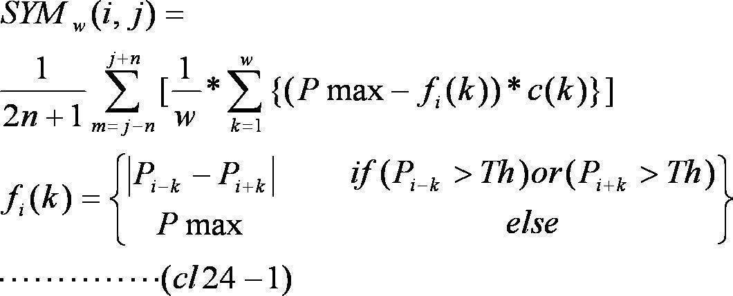
または、
に基づいて、前記注目画素の前記対称性評価値を算出する、
請求項17または18に記載の物体検出装置。 - 前記対称性評価部は、
前記SYMw(i、j)の最大値maxSYMを取得するとともに、前記SYMw(i、j)が最大値となるときの前記対称性評価領域の前記第1方向の幅2w+1に基づいて、前記対称幅を決定する、
請求項24に記載の物体検出装置。 - 前記対称性評価部は、
前記特徴量抽出画像上の画素値が0または正の値をとり、前記画像特徴量が大きい程、大きな値をとるものとし、前記特徴量抽出画像上の画素値の取り得る最大値以上の所定の値をPmaxとし、
前記特徴量抽出画像上の座標(i,j)の注目画素の画素値をPiとし、前記注目画素から前記第1方向の一方向である第1探索方向にk画素(kは自然数)離れた画素の画素値をPi-kとし、前記注目画素から前記第1方向の前記第1探索方向と逆方向である第2検索方向にk画素離れた画素の画素値をPi+kとし、
前記対称性評価領域の第1方向の幅を2w+1とし、
前記対称性評価領域の前記第2方向の幅を2n+1とし、
所定の閾値をThとし、前記注目画素からの距離kについての重み付け関数をc(k)とするとき、
前記対称性評価領域の第1方向の幅2w+1(wは自然数)を変化させながら、

または、
に基づいて、前記注目画素の前記対称性評価値を算出する、
請求項17または18に記載の物体検出装置。 - 前記対称性評価部は、
前記SYMw(i、j)の最大値maxSYMを取得するとともに、前記SYMw(i、j)が最大値となるときの前記対称性評価領域の前記第1方向の幅2w+1に基づいて、前記対称幅を決定する、
請求項26に記載の物体検出装置。 - 前記重み付け関数c(k)は、kについての単調増加関数である、
請求項19、20、22~26のいずれかに記載の物体検出装置。 - 前記重み付け関数c(k)は、kについての単調減少関数である、
請求項19、20、22~26のいずれかに記載の物体検出装置。 - 前記対称性評価部は、
前記画像の前記第1方向の画素数をH(Hは自然数)とすると、
(1)前記注目画素の前記第1方向の位置を示す列iが(H/2)以下の場合、前記対称性評価領域の前記第1方向の幅の半分であるwを、1≦w≦(i-1)の範囲で変化させて、前記対称性評価値を算出し、
(2)前記注目画素の前記第1方向の位置を示す列iが(H/2)より大きい場合、前記対称性評価領域の前記第1方向の幅の半分であるwを、1≦w≦(H-i)の範囲で変化させて、前記対称性評価値を算出する、
請求項17から29のいずれかに記載の物体検出装置。 - 画像特徴量は、前記画像のエッジ強度である、
請求項1から30のいずれかに記載の物体検出装置。 - 画像特徴量は、前記画像の特定の色成分の強度である、
請求項1から30のいずれかに記載の物体検出装置。 - 画像を入力する画像入力ステップと、
前記画像から所定の画像特徴量を抽出して特徴量抽出画像を生成する画像特徴量抽出ステップと、
前記特徴量抽出画像に対して、処理対象である注目画素ごとに、画像上の第1方向に関する対称性を評価するとともに、前記第1方向に関する対称幅を算出する対称性評価ステップと、
前記複数の評価画素の中で対称性が所定の基準を上回る画素を対称中心画素として検出する中心検出ステップと、
前記対称中心画素の前記対称幅に基づいて前記画像に含まれる対称性を有する物体の前記第1方向に関する物体幅を検出し、前記対称中心画素の前記第1方向と直交する第2方向に関する分布に基づいて前記物体の前記第2方向に関する物体幅を検出する物体領域検出ステップと、
を備える物体検出方法をコンピュータに実行させるためのプログラム。 - 対称性評価ステップは、
前記特徴量抽出画像に対して、処理対象である注目画素ごとに、前記画像上の第1方向についての対称性を評価するための領域である対称性評価領域を前記第1方向と直交する第2方向の中心軸を中心として対称となるように設定し、前記対称性評価領域の大きさを変化させながら、前記対称性評価領域に含まれ、前記中心軸について対称となる位置に存在する画素群の画像特徴量の相関値に対して、前記画素群の画像特徴量による重み付けを行った値を導出することで、前記第1方向の対称性の度合いを示す対称性評価値を取得する、
請求項33に記載の物体検出方法をコンピュータに実行させるためのプログラム。 - 対称性評価ステップは、
前記特徴量抽出画像に対して、処理対象である注目画素ごとに、前記画像上の第1方向についての対称性を評価するための領域である対称性評価領域を前記第1方向と直交する第2方向の所定の軸である中心軸を中心として対称となるように設定し、前記対称性評価領域の大きさを変化させながら、前記対称性評価領域に含まれ、前記中心軸について対称となる位置に存在する画素群の画像特徴量の相関値に対して、前記画素群の前記中心軸からの距離に基づく重み付けを行った値を導出することで、前記第1方向の対称性の度合いを示す対称性評価値を取得する、
請求項33に記載の物体検出方法をコンピュータに実行させるためのプログラム。
Priority Applications (3)
| Application Number | Priority Date | Filing Date | Title |
|---|---|---|---|
| US14/382,654 US9514545B2 (en) | 2012-03-28 | 2013-03-11 | Object detection apparatus and storage medium |
| CN201380014828.6A CN104205170B (zh) | 2012-03-28 | 2013-03-11 | 物体检测装置及物体检测方法 |
| EP13768099.7A EP2819094B1 (en) | 2012-03-28 | 2013-03-11 | Object detection apparatus and program |
Applications Claiming Priority (4)
| Application Number | Priority Date | Filing Date | Title |
|---|---|---|---|
| JP2012073854 | 2012-03-28 | ||
| JP2012-073854 | 2012-03-28 | ||
| JP2012229095A JP6008367B2 (ja) | 2012-03-28 | 2012-10-16 | 物体検出装置およびプログラム |
| JP2012-229095 | 2012-10-16 |
Publications (1)
| Publication Number | Publication Date |
|---|---|
| WO2013146206A1 true WO2013146206A1 (ja) | 2013-10-03 |
Family
ID=49259474
Family Applications (1)
| Application Number | Title | Priority Date | Filing Date |
|---|---|---|---|
| PCT/JP2013/056587 Ceased WO2013146206A1 (ja) | 2012-03-28 | 2013-03-11 | 物体検出装置およびプログラム |
Country Status (5)
| Country | Link |
|---|---|
| US (1) | US9514545B2 (ja) |
| EP (1) | EP2819094B1 (ja) |
| JP (1) | JP6008367B2 (ja) |
| CN (1) | CN104205170B (ja) |
| WO (1) | WO2013146206A1 (ja) |
Cited By (1)
| Publication number | Priority date | Publication date | Assignee | Title |
|---|---|---|---|---|
| WO2021132227A1 (ja) * | 2019-12-23 | 2021-07-01 | 京セラ株式会社 | 情報処理装置、センシング装置、移動体及び情報処理方法 |
Families Citing this family (7)
| Publication number | Priority date | Publication date | Assignee | Title |
|---|---|---|---|---|
| JP6393230B2 (ja) * | 2015-04-20 | 2018-09-19 | 株式会社日立製作所 | オブジェクト検出方法及び画像検索システム |
| CN110163221B (zh) * | 2019-05-28 | 2022-12-09 | 腾讯科技(深圳)有限公司 | 在图像中进行物体检测的方法、装置、车辆、机器人 |
| CN114938673B (zh) * | 2020-01-06 | 2025-10-03 | 发那科株式会社 | 物体检测装置以及模型图案评价装置 |
| JP7755427B2 (ja) * | 2021-09-24 | 2025-10-16 | 株式会社Subaru | 画像処理装置および車両 |
| KR102702961B1 (ko) * | 2021-12-29 | 2024-09-04 | 경일대학교산학협력단 | 이미지로부터 객체를 식별하기 위한 전자 장치 및 방법 |
| CN115249253B (zh) * | 2022-07-18 | 2026-01-27 | 北京城市网邻信息技术有限公司 | 图像裁剪方法、装置、电子设备及存储介质 |
| CN118485668B (zh) * | 2024-07-16 | 2024-09-17 | 领视科技成都有限公司 | 走行式接触网几何参数智能测量装置及方法 |
Citations (6)
| Publication number | Priority date | Publication date | Assignee | Title |
|---|---|---|---|---|
| JPH10162118A (ja) * | 1996-11-29 | 1998-06-19 | Canon Inc | 画像処理装置及び方法 |
| JP2000039306A (ja) * | 1998-07-22 | 2000-02-08 | Nec Corp | 車両領域検出装置及び車両領域検定方法 |
| JP2004110543A (ja) * | 2002-09-19 | 2004-04-08 | Toyota Central Res & Dev Lab Inc | 顔画像処理装置及びプログラム |
| JP2005157648A (ja) * | 2003-11-25 | 2005-06-16 | Toyota Motor Corp | 運転者認識装置 |
| JP2010176531A (ja) * | 2009-01-30 | 2010-08-12 | Secom Co Ltd | 画像監視装置 |
| JP2010267257A (ja) | 2009-04-16 | 2010-11-25 | Panasonic Corp | 画像処理装置、画像処理方法及び画像処理プログラム |
Family Cites Families (10)
| Publication number | Priority date | Publication date | Assignee | Title |
|---|---|---|---|---|
| EP0356727A3 (en) | 1988-08-09 | 1991-06-05 | Schlumberger Technologies Inc | Symmetrie-based target position measurement |
| DE60226505D1 (de) * | 2002-01-18 | 2008-06-19 | Star Agency For Science Techol | Verfahren und vorrichtung zur bestimmung von symmetrie in 2d- und 3d-bildern |
| CN101029824B (zh) * | 2006-02-28 | 2011-10-26 | 东软集团股份有限公司 | 基于车辆特征的车辆定位方法和装置 |
| EP1996959A4 (en) * | 2006-03-03 | 2012-02-29 | Medic Vision Brain Technologies Ltd | SYSTEM AND METHOD FOR PRIORITIZE PRIORITIZATION AND AUTOMATIC ANALYSIS OF MEDICAL IMAGES |
| US8204278B2 (en) * | 2006-11-28 | 2012-06-19 | Fujitsu Limited | Image recognition method |
| WO2008065717A1 (fr) | 2006-11-29 | 2008-06-05 | Fujitsu Limited | Système et procédé de détection de piéton |
| US8494297B2 (en) * | 2007-04-05 | 2013-07-23 | Adobe Systems Incorporated | Automatic detection and mapping of symmetries in an image |
| JP4917961B2 (ja) | 2007-05-22 | 2012-04-18 | 株式会社日本自動車部品総合研究所 | 車載用車両灯検出装置および車両用照明装置 |
| JP2010177780A (ja) | 2009-01-27 | 2010-08-12 | Toyota Motor Corp | 撮像装置 |
| JP5316337B2 (ja) | 2009-09-17 | 2013-10-16 | 日本電気株式会社 | 画像認識システム、方法、及び、プログラム |
-
2012
- 2012-10-16 JP JP2012229095A patent/JP6008367B2/ja not_active Expired - Fee Related
-
2013
- 2013-03-11 US US14/382,654 patent/US9514545B2/en not_active Expired - Fee Related
- 2013-03-11 WO PCT/JP2013/056587 patent/WO2013146206A1/ja not_active Ceased
- 2013-03-11 EP EP13768099.7A patent/EP2819094B1/en not_active Not-in-force
- 2013-03-11 CN CN201380014828.6A patent/CN104205170B/zh not_active Expired - Fee Related
Patent Citations (6)
| Publication number | Priority date | Publication date | Assignee | Title |
|---|---|---|---|---|
| JPH10162118A (ja) * | 1996-11-29 | 1998-06-19 | Canon Inc | 画像処理装置及び方法 |
| JP2000039306A (ja) * | 1998-07-22 | 2000-02-08 | Nec Corp | 車両領域検出装置及び車両領域検定方法 |
| JP2004110543A (ja) * | 2002-09-19 | 2004-04-08 | Toyota Central Res & Dev Lab Inc | 顔画像処理装置及びプログラム |
| JP2005157648A (ja) * | 2003-11-25 | 2005-06-16 | Toyota Motor Corp | 運転者認識装置 |
| JP2010176531A (ja) * | 2009-01-30 | 2010-08-12 | Secom Co Ltd | 画像監視装置 |
| JP2010267257A (ja) | 2009-04-16 | 2010-11-25 | Panasonic Corp | 画像処理装置、画像処理方法及び画像処理プログラム |
Non-Patent Citations (1)
| Title |
|---|
| See also references of EP2819094A4 |
Cited By (3)
| Publication number | Priority date | Publication date | Assignee | Title |
|---|---|---|---|---|
| WO2021132227A1 (ja) * | 2019-12-23 | 2021-07-01 | 京セラ株式会社 | 情報処理装置、センシング装置、移動体及び情報処理方法 |
| JPWO2021132227A1 (ja) * | 2019-12-23 | 2021-07-01 | ||
| JP7254967B2 (ja) | 2019-12-23 | 2023-04-10 | 京セラ株式会社 | 情報処理装置、センシング装置、移動体及び情報処理方法 |
Also Published As
| Publication number | Publication date |
|---|---|
| JP2013228995A (ja) | 2013-11-07 |
| US9514545B2 (en) | 2016-12-06 |
| EP2819094B1 (en) | 2018-04-18 |
| CN104205170A (zh) | 2014-12-10 |
| CN104205170B (zh) | 2018-03-09 |
| JP6008367B2 (ja) | 2016-10-19 |
| EP2819094A4 (en) | 2015-12-09 |
| US20150030251A1 (en) | 2015-01-29 |
| EP2819094A1 (en) | 2014-12-31 |
Similar Documents
| Publication | Publication Date | Title |
|---|---|---|
| JP6008367B2 (ja) | 物体検出装置およびプログラム | |
| Liu et al. | Single image dehazing via large sky region segmentation and multiscale opening dark channel model | |
| JP7159384B2 (ja) | 画像処理装置、画像処理方法、及びプログラム | |
| JP5779089B2 (ja) | エッジ検出装置、エッジ検出プログラム、およびエッジ検出方法 | |
| JP2011530880A (ja) | エッジ検出を使用して奥行きデータを生成するシステム及び方法 | |
| JP6818463B2 (ja) | 画像処理装置、画像処理方法及びプログラム | |
| JP5911063B2 (ja) | 物体検出装置およびプログラム | |
| JP5911062B2 (ja) | 物体検出装置およびプログラム | |
| US12380534B2 (en) | Training apparatus, training method, and medium | |
| US20160260199A1 (en) | Image processing apparatus, image processing method, and storage medium | |
| US11164286B2 (en) | Image processing apparatus, image processing method, and storage medium | |
| CN108985307A (zh) | 一种基于遥感影像的水体提取方法及系统 | |
| JP5446641B2 (ja) | 画像処理装置、画像処理方法及び画像処理プログラム | |
| JP6552248B2 (ja) | 画像処理装置及び方法、撮像装置、並びにプログラム | |
| KR101535196B1 (ko) | 질감 특성을 고려한 영상 분할 장치 및 그 방법 | |
| JP5704069B2 (ja) | 画像入力装置 | |
| JP6314281B1 (ja) | 画像処理方法及び前景領域取得方法 | |
| JP6405638B2 (ja) | 被写体検出装置、撮像装置及びプログラム | |
| CN114882436A (zh) | 一种目标检测方法、装置、电子设备及存储介质 | |
| JP5605492B2 (ja) | 画像処理装置、画像処理方法及び画像処理プログラム | |
| JP2019036972A (ja) | 被写体検出装置、撮像装置及びプログラム |
Legal Events
| Date | Code | Title | Description |
|---|---|---|---|
| 121 | Ep: the epo has been informed by wipo that ep was designated in this application |
Ref document number: 13768099 Country of ref document: EP Kind code of ref document: A1 |
|
| WWE | Wipo information: entry into national phase |
Ref document number: 14382654 Country of ref document: US |
|
| WWE | Wipo information: entry into national phase |
Ref document number: 2013768099 Country of ref document: EP |
|
| NENP | Non-entry into the national phase |
Ref country code: DE |