WO2013146409A1 - ブーム駆動装置 - Google Patents
ブーム駆動装置 Download PDFInfo
- Publication number
- WO2013146409A1 WO2013146409A1 PCT/JP2013/057632 JP2013057632W WO2013146409A1 WO 2013146409 A1 WO2013146409 A1 WO 2013146409A1 JP 2013057632 W JP2013057632 W JP 2013057632W WO 2013146409 A1 WO2013146409 A1 WO 2013146409A1
- Authority
- WO
- WIPO (PCT)
- Prior art keywords
- boom
- valve
- switching valve
- regenerative
- pilot
- Prior art date
- Legal status (The legal status is an assumption and is not a legal conclusion. Google has not performed a legal analysis and makes no representation as to the accuracy of the status listed.)
- Ceased
Links
Images


Classifications
-
- E—FIXED CONSTRUCTIONS
- E02—HYDRAULIC ENGINEERING; FOUNDATIONS; SOIL SHIFTING
- E02F—DREDGING; SOIL-SHIFTING
- E02F9/00—Component parts of dredgers or soil-shifting machines, not restricted to one of the kinds covered by groups E02F3/00 - E02F7/00
- E02F9/20—Drives; Control devices
- E02F9/22—Hydraulic or pneumatic drives
-
- F—MECHANICAL ENGINEERING; LIGHTING; HEATING; WEAPONS; BLASTING
- F15—FLUID-PRESSURE ACTUATORS; HYDRAULICS OR PNEUMATICS IN GENERAL
- F15B—SYSTEMS ACTING BY MEANS OF FLUIDS IN GENERAL; FLUID-PRESSURE ACTUATORS, e.g. SERVOMOTORS; DETAILS OF FLUID-PRESSURE SYSTEMS, NOT OTHERWISE PROVIDED FOR
- F15B15/00—Fluid-actuated devices for displacing a member from one position to another; Gearing associated therewith
- F15B15/20—Other details, e.g. assembly with regulating devices
-
- E—FIXED CONSTRUCTIONS
- E02—HYDRAULIC ENGINEERING; FOUNDATIONS; SOIL SHIFTING
- E02F—DREDGING; SOIL-SHIFTING
- E02F9/00—Component parts of dredgers or soil-shifting machines, not restricted to one of the kinds covered by groups E02F3/00 - E02F7/00
- E02F9/20—Drives; Control devices
- E02F9/2058—Electric or electro-mechanical or mechanical control devices of vehicle sub-units
- E02F9/2062—Control of propulsion units
- E02F9/2075—Control of propulsion units of the hybrid type
-
- E—FIXED CONSTRUCTIONS
- E02—HYDRAULIC ENGINEERING; FOUNDATIONS; SOIL SHIFTING
- E02F—DREDGING; SOIL-SHIFTING
- E02F9/00—Component parts of dredgers or soil-shifting machines, not restricted to one of the kinds covered by groups E02F3/00 - E02F7/00
- E02F9/20—Drives; Control devices
- E02F9/22—Hydraulic or pneumatic drives
- E02F9/2203—Arrangements for controlling the attitude of actuators, e.g. speed, floating function
- E02F9/2207—Arrangements for controlling the attitude of actuators, e.g. speed, floating function for reducing or compensating oscillations
-
- E—FIXED CONSTRUCTIONS
- E02—HYDRAULIC ENGINEERING; FOUNDATIONS; SOIL SHIFTING
- E02F—DREDGING; SOIL-SHIFTING
- E02F9/00—Component parts of dredgers or soil-shifting machines, not restricted to one of the kinds covered by groups E02F3/00 - E02F7/00
- E02F9/20—Drives; Control devices
- E02F9/22—Hydraulic or pneumatic drives
- E02F9/2217—Hydraulic or pneumatic drives with energy recovery arrangements, e.g. using accumulators, flywheels
-
- E—FIXED CONSTRUCTIONS
- E02—HYDRAULIC ENGINEERING; FOUNDATIONS; SOIL SHIFTING
- E02F—DREDGING; SOIL-SHIFTING
- E02F9/00—Component parts of dredgers or soil-shifting machines, not restricted to one of the kinds covered by groups E02F3/00 - E02F7/00
- E02F9/20—Drives; Control devices
- E02F9/22—Hydraulic or pneumatic drives
- E02F9/2278—Hydraulic circuits
- E02F9/2282—Systems using center bypass type changeover valves
-
- E—FIXED CONSTRUCTIONS
- E02—HYDRAULIC ENGINEERING; FOUNDATIONS; SOIL SHIFTING
- E02F—DREDGING; SOIL-SHIFTING
- E02F9/00—Component parts of dredgers or soil-shifting machines, not restricted to one of the kinds covered by groups E02F3/00 - E02F7/00
- E02F9/20—Drives; Control devices
- E02F9/22—Hydraulic or pneumatic drives
- E02F9/2278—Hydraulic circuits
- E02F9/2292—Systems with two or more pumps
-
- E—FIXED CONSTRUCTIONS
- E02—HYDRAULIC ENGINEERING; FOUNDATIONS; SOIL SHIFTING
- E02F—DREDGING; SOIL-SHIFTING
- E02F9/00—Component parts of dredgers or soil-shifting machines, not restricted to one of the kinds covered by groups E02F3/00 - E02F7/00
- E02F9/20—Drives; Control devices
- E02F9/22—Hydraulic or pneumatic drives
- E02F9/2278—Hydraulic circuits
- E02F9/2296—Systems with a variable displacement pump
-
- F—MECHANICAL ENGINEERING; LIGHTING; HEATING; WEAPONS; BLASTING
- F04—POSITIVE - DISPLACEMENT MACHINES FOR LIQUIDS; PUMPS FOR LIQUIDS OR ELASTIC FLUIDS
- F04B—POSITIVE-DISPLACEMENT MACHINES FOR LIQUIDS; PUMPS
- F04B7/00—Piston machines or pumps characterised by having positively-driven valving
- F04B7/02—Piston machines or pumps characterised by having positively-driven valving the valving being fluid-actuated
-
- F—MECHANICAL ENGINEERING; LIGHTING; HEATING; WEAPONS; BLASTING
- F15—FLUID-PRESSURE ACTUATORS; HYDRAULICS OR PNEUMATICS IN GENERAL
- F15B—SYSTEMS ACTING BY MEANS OF FLUIDS IN GENERAL; FLUID-PRESSURE ACTUATORS, e.g. SERVOMOTORS; DETAILS OF FLUID-PRESSURE SYSTEMS, NOT OTHERWISE PROVIDED FOR
- F15B21/00—Common features of fluid actuator systems; Fluid-pressure actuator systems or details thereof, not covered by any other group of this subclass
- F15B21/14—Energy-recuperation means
-
- F—MECHANICAL ENGINEERING; LIGHTING; HEATING; WEAPONS; BLASTING
- F15—FLUID-PRESSURE ACTUATORS; HYDRAULICS OR PNEUMATICS IN GENERAL
- F15B—SYSTEMS ACTING BY MEANS OF FLUIDS IN GENERAL; FLUID-PRESSURE ACTUATORS, e.g. SERVOMOTORS; DETAILS OF FLUID-PRESSURE SYSTEMS, NOT OTHERWISE PROVIDED FOR
- F15B2211/00—Circuits for servomotor systems
- F15B2211/30—Directional control
- F15B2211/305—Directional control characterised by the type of valves
- F15B2211/3056—Assemblies of multiple valves
- F15B2211/30565—Assemblies of multiple valves having multiple valves for a single output member, e.g. for creating higher valve function by use of multiple valves like two 2/2-valves replacing a 5/3-valve
- F15B2211/3058—Assemblies of multiple valves having multiple valves for a single output member, e.g. for creating higher valve function by use of multiple valves like two 2/2-valves replacing a 5/3-valve having additional valves for interconnecting the fluid chambers of a double-acting actuator, e.g. for regeneration mode or for floating mode
-
- F—MECHANICAL ENGINEERING; LIGHTING; HEATING; WEAPONS; BLASTING
- F15—FLUID-PRESSURE ACTUATORS; HYDRAULICS OR PNEUMATICS IN GENERAL
- F15B—SYSTEMS ACTING BY MEANS OF FLUIDS IN GENERAL; FLUID-PRESSURE ACTUATORS, e.g. SERVOMOTORS; DETAILS OF FLUID-PRESSURE SYSTEMS, NOT OTHERWISE PROVIDED FOR
- F15B2211/00—Circuits for servomotor systems
- F15B2211/30—Directional control
- F15B2211/315—Directional control characterised by the connections of the valve or valves in the circuit
- F15B2211/31552—Directional control characterised by the connections of the valve or valves in the circuit being connected to an output member and a return line
- F15B2211/31558—Directional control characterised by the connections of the valve or valves in the circuit being connected to an output member and a return line having a single output member
-
- F—MECHANICAL ENGINEERING; LIGHTING; HEATING; WEAPONS; BLASTING
- F15—FLUID-PRESSURE ACTUATORS; HYDRAULICS OR PNEUMATICS IN GENERAL
- F15B—SYSTEMS ACTING BY MEANS OF FLUIDS IN GENERAL; FLUID-PRESSURE ACTUATORS, e.g. SERVOMOTORS; DETAILS OF FLUID-PRESSURE SYSTEMS, NOT OTHERWISE PROVIDED FOR
- F15B2211/00—Circuits for servomotor systems
- F15B2211/60—Circuit components or control therefor
- F15B2211/63—Electronic controllers
- F15B2211/6303—Electronic controllers using input signals
- F15B2211/634—Electronic controllers using input signals representing a state of a valve
-
- F—MECHANICAL ENGINEERING; LIGHTING; HEATING; WEAPONS; BLASTING
- F15—FLUID-PRESSURE ACTUATORS; HYDRAULICS OR PNEUMATICS IN GENERAL
- F15B—SYSTEMS ACTING BY MEANS OF FLUIDS IN GENERAL; FLUID-PRESSURE ACTUATORS, e.g. SERVOMOTORS; DETAILS OF FLUID-PRESSURE SYSTEMS, NOT OTHERWISE PROVIDED FOR
- F15B2211/00—Circuits for servomotor systems
- F15B2211/60—Circuit components or control therefor
- F15B2211/665—Methods of control using electronic components
-
- F—MECHANICAL ENGINEERING; LIGHTING; HEATING; WEAPONS; BLASTING
- F15—FLUID-PRESSURE ACTUATORS; HYDRAULICS OR PNEUMATICS IN GENERAL
- F15B—SYSTEMS ACTING BY MEANS OF FLUIDS IN GENERAL; FLUID-PRESSURE ACTUATORS, e.g. SERVOMOTORS; DETAILS OF FLUID-PRESSURE SYSTEMS, NOT OTHERWISE PROVIDED FOR
- F15B2211/00—Circuits for servomotor systems
- F15B2211/70—Output members, e.g. hydraulic motors or cylinders or control therefor
- F15B2211/705—Output members, e.g. hydraulic motors or cylinders or control therefor characterised by the type of output members or actuators
- F15B2211/7051—Linear output members
- F15B2211/7053—Double-acting output members
-
- F—MECHANICAL ENGINEERING; LIGHTING; HEATING; WEAPONS; BLASTING
- F15—FLUID-PRESSURE ACTUATORS; HYDRAULICS OR PNEUMATICS IN GENERAL
- F15B—SYSTEMS ACTING BY MEANS OF FLUIDS IN GENERAL; FLUID-PRESSURE ACTUATORS, e.g. SERVOMOTORS; DETAILS OF FLUID-PRESSURE SYSTEMS, NOT OTHERWISE PROVIDED FOR
- F15B2211/00—Circuits for servomotor systems
- F15B2211/80—Other types of control related to particular problems or conditions
- F15B2211/86—Control during or prevention of abnormal conditions
- F15B2211/8606—Control during or prevention of abnormal conditions the abnormal condition being a shock
-
- F—MECHANICAL ENGINEERING; LIGHTING; HEATING; WEAPONS; BLASTING
- F15—FLUID-PRESSURE ACTUATORS; HYDRAULICS OR PNEUMATICS IN GENERAL
- F15B—SYSTEMS ACTING BY MEANS OF FLUIDS IN GENERAL; FLUID-PRESSURE ACTUATORS, e.g. SERVOMOTORS; DETAILS OF FLUID-PRESSURE SYSTEMS, NOT OTHERWISE PROVIDED FOR
- F15B2211/00—Circuits for servomotor systems
- F15B2211/80—Other types of control related to particular problems or conditions
- F15B2211/88—Control measures for saving energy
Definitions
- the present invention relates to control of a boom drive device that performs regenerative power generation using a return fluid from a boom cylinder that raises and lowers a boom.
- a construction machine having a boom generally includes a boom cylinder that rotates the boom up and down.
- JP2011-179541A issued by the Japan Patent Office uses a return fluid from a boom cylinder when the boom is rotated downward to rotate the fluid pressure motor and drives the generator with the rotational torque of the fluid pressure motor.
- a regenerative power generator is proposed.
- the boom cylinder has a rod side chamber defined by the piston and an opposite piston side chamber. Hydraulic oil is selectively supplied to one of the rod side chamber and the piston side chamber via a switching valve that switches according to the operation direction of the boom cylinder. The switching valve also connects the other of the rod side chamber and the piston side chamber to the tank.
- This regenerative power generation device is provided with a regenerative control spool valve in the passage connecting the switching valve and the piston side chamber that discharges hydraulic oil as the boom cylinder contracts, and a part of the return fluid is regenerated through the regenerative control spool valve. It is supplied to a fluid pressure motor for power generation.
- the regenerative control spool valve has an operation position for blocking communication between the piston side chamber and the regenerative fluid pressure motor, and an operation position for supplying a part of the return fluid to the regenerative fluid pressure motor. Furthermore, the regenerative control spool valve continuously changes the opening of the regenerative passage from the regenerative control spool valve to the regenerative fluid pressure motor during the position switching process, thereby changing the regenerative flow rate according to the displacement of the spool. I have control.
- the sum of the regenerative flow rate and the reflux flow rate constitutes the total flow rate of the return fluid from the boom cylinder.
- the lowering speed of the boom cylinder is determined depending on the total flow rate of the return fluid.
- the total amount of return fluid is determined according to the operation amount of the switching valve.
- the flow rate fluctuation of the return fluid at the start of the fluid pressure motor affects the boom lowering speed, which may make the operator feel uncomfortable.
- An object of the present invention is to reduce the uncomfortable feeling felt by the operator when using the return fluid of the boom cylinder as regenerative energy.
- the present invention includes a boom cylinder that extends by supplying hydraulic oil to a working chamber to raise the boom, and lowers the boom in response to the discharge of hydraulic oil from the working chamber.
- the displacement between the position where the chamber is connected to the pump and the position where the working chamber is connected to the tank, and when the working chamber is displaced to the position where the working chamber is connected to the tank, along with the displacement, the connection cross section of the hydraulic oil and the tank A boom switching valve configured to increase the pressure, a generator, a regenerative passage for rotating and driving the generator by diverting a part of the hydraulic oil discharged from the working chamber to the tank upstream of the boom switching valve, and a regenerative passage And a regenerative control valve that opens and closes the boom drive device.
- the boom drive device has a sensor that detects a displacement position of the boom switching valve, and the displacement amount of the boom switching valve exceeds a predetermined amount when the boom switching valve is displaced to a position that connects the working chamber to the tank. And a programmable controller programmed to open the regenerative control valve.
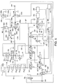
- FIG. 1 is a hydraulic circuit diagram of a boom drive apparatus according to a first embodiment of the present invention.
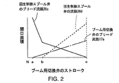
- FIG. 2 is a diagram showing the switching timing of the regeneration control spool valve according to the first embodiment of the present invention.
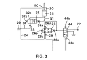
- FIG. 3 is a hydraulic circuit diagram of a boom drive apparatus according to a second embodiment of the present invention.
- FIG. 4 is a hydraulic circuit diagram of a boom drive apparatus according to a third embodiment of the present invention.
- FIG. 5 is a hydraulic circuit diagram of a boom drive apparatus according to a fourth embodiment of the present invention.
- the boom drive device includes a variable capacity first main pump MP1, a variable capacity second main pump MP2, and a variable capacity assist pump AP.
- the discharge port of the first main pump MP1 is connected to the first circuit system via the first switching valve V1.
- the discharge port of the second main pump MP2 is connected to the second circuit system via the second switching valve V2.
- the discharge port of the assist pump AP merges with the discharge port of the first main pump MP1 via the first switching valve V1.
- the first main pump MP1, the second main pump MP2, and the assist pump AP are all configured by pumps that supply hydraulic oil under pressure.
- the operation position of the valve when there is no external energy supply is indicated.
- the operating position of the valve that receives the energy supply from the off position and the outside is referred to as the on position.
- the on position When there are a plurality of on-positions, they are called a first on-position and a second on-position.
- the first switching valve V1 is a 4-port 2-position spool type switching valve.
- a pilot chamber is provided facing one end of the spool, and the other end of the spool is supported by a spring. When the pilot pressure is not supplied to the pilot chamber, the first switching valve V1 is held at the off position shown in the drawing by the biasing force of the spring.
- the first switching valve V1 in the off position supplies the discharge oil of the first main pump MP1 to the first circuit system, while the discharge oil of the variable displacement type assist pump AP passes through the check valve to the first main pump MP1. Merge into the discharge port.
- the second switching valve V2 is a 6-port, 3-position spool type switching valve, provided with pilot chambers facing both sides of the spool and supported by a centering spring.
- the second switching valve V2 is normally held in the off position shown in the drawing by the spring force of the centering spring.
- the second switching valve V2 supplies the discharge oil of the second main pump MP2 to the second circuit system, and joins the discharge oil of the assist pump AP to the discharge port of the second main pump MP2.
- the merging of the discharge oil of the assist pump AP to the discharge port of the second main pump MP2 also occurs.
- the supply of the oil discharged from the 2 main pump MP2 to the second circuit supply system is also cut off.
- the oil discharged from the second main pump MP2 is supplied to the hydraulic motor M that drives the assist pump AP.
- the supply of the discharge oil of the second main pump MP2 to the hydraulic motor M is interrupted.
- the pilot pressure of the first switching valve V1 is supplied from the pilot hydraulic power source PP through the solenoid valve 1.
- the solenoid valve 1 is switched to an on-position in which the pilot chamber is shut off from the pilot hydraulic power source PP in the illustrated off position where the solenoid is not excited, and the discharge oil of the pilot hydraulic power source PP is supplied to the pilot chamber when the solenoid is excited. .
- One pilot chamber of the second switching valve V2 is connected to the pilot hydraulic pressure source PP through the electromagnetic valve 2a.
- the other pilot chamber of the second switching valve V2 is connected to the pilot hydraulic pressure source PP via the electromagnetic valve 2b.
- the solenoid valves 2a and 2b both shut off the pilot chamber from the pilot hydraulic power source PP in the off position shown in the diagram where the solenoid is not excited, and the solenoid discharges the pilot oil from the pilot hydraulic power source PP to the pilot chamber. Switch to the supplied on-position.
- Solenoids of solenoid valves 1, 2a, 2b are connected to controller C.
- the controller C includes a microcomputer having a central processing unit (CPU), a read only memory (ROM), a random access memory (RAM), and an input / output interface (I / O interface). It is also possible to configure the controller with a plurality of microcomputers.
- CPU central processing unit
- ROM read only memory
- RAM random access memory
- I / O interface input / output interface
- Controller C excites or de-energizes solenoids of solenoid valves 1, 2a, 2b in response to an input signal from the construction machine operator.
- 1st main pump MP1 and 2nd main pump MP2 are rotationally driven by the engine E provided with the rotational speed sensor which is not shown in figure.
- the engine E is provided with a generator 3 that generates power using surplus torque.
- the first circuit system connected to the first main pump MP1 includes a switching valve 4 for controlling the turning motor, a switching valve 5 for controlling the arm cylinder, and a switching for the second speed of the boom for controlling the boom cylinder BC.
- a valve 6, a switching valve 7 for controlling the auxiliary attachment, and a switching valve 8 for controlling the left traveling motor are provided.
- the switching valve 4-8 is connected to the first main pump MP1 via the neutral flow path 9 and the parallel path 10, and the first switching valve V1.
- a pilot pressure control throttle 11 for generating a pilot pressure is provided downstream of the switching valve 8 for the left travel motor in the neutral flow path 9.
- the throttle 11 generates a high pilot pressure on the upstream side if the flow rate is high, and generates a low pilot pressure on the upstream side if the flow rate is low.
- the throttle 11 generates a pilot pressure corresponding to the operation amount of the switching valve 4-8 located on the upstream side.
- a pilot flow path 12 is connected between the switching valve 8 and the throttle 11 of the neutral flow path 9.
- the pilot flow path 12 is connected to a regulator 14 that controls the tilt angle of the first main pump MP1 via an electromagnetic switching valve 13.
- the electromagnetic switching valve 13 is a valve that supplies a pilot pressure to the regulator 14, and selects the pilot flow path 12 and the pilot hydraulic power source PP as a pilot pressure source according to its position and connects to the regulator 14. In the off position shown in the figure, the pressure in the pilot flow path 12 is supplied to the regulator 14 as the pilot pressure. The electromagnetic switching valve 13 is switched to the on position when supplied with an exciting current, and supplies the pressure of the pilot hydraulic power source PP to the regulator 14 as the pilot pressure.
- the solenoid of the electromagnetic switching valve 13 is connected to the controller C.
- the controller C supplies an excitation current to the electromagnetic switching valve 13 to switch to the on position.
- the controller C de-energizes the solenoid unless a signal is input from the operator.
- the electromagnetic switching valve 13 is held in the off position.
- the regulator 14 controls the tilt angle of the first main pump MP1 in inverse proportion to the pilot pressure of the pilot flow path 12, and sets the hydraulic oil discharge amount per rotation of the first main pump MP1.
- the electromagnetic switching valve 13 When all of the switching valves 4-8 are kept in the off position, that is, when the swing motor, arm cylinder, boom cylinder BC, spare attachment, and left travel motor are not operated, the electromagnetic switching valve 13 is connected to the first main pump MP1. It has a role to make the discharge amount smaller than in other cases. For example, this condition corresponds to a warm-up operation where energy loss is to be reduced.
- the second circuit system connected to the second main pump MP2 includes, in order from the upstream side, a switching valve 15 that controls the right traveling motor, a switching valve 16 that controls the bucket cylinder, and a boom switching that controls the boom cylinder BC. There is provided a valve 17 and a switching valve 18 for the second arm speed for controlling the arm cylinder.
- the switching valve 15-18 is connected to the second main pump MP2 via the neutral flow path 19 and the second switching valve V2.
- the switching valve 16 and the boom switching valve 17 are connected to the second main pump MP2 via the parallel passage 20 and the second switching valve V2.
- a throttle 21 for pilot pressure control is provided downstream of the switching valve 18 in the neutral flow path 19.
- the throttle 21 supplies the upstream pressure as a pilot pressure to the regulator 23 of the second main pump MP2 via the pilot flow path 22.
- the regulator 23 controls the tilt angle of the second main pump MP2 in inverse proportion to the pilot pressure, and sets the hydraulic oil discharge amount per rotation of the second main pump MP2.
- the boom switching valve 17 is a 6-port 3-position spool type switching valve.
- the boom switching valve 17 has a port connected to the neutral flow path 19 as an input port, a port connected to the parallel flow path 20, and a port connected to the tank.
- two actuator ports as output ports and a port connected to the neutral flow path 19 are provided.
- One of the two actuator ports is connected to the piston side chamber 25 of the boom cylinder BC via the passage 24.
- the other of the two actuator ports is connected to the rod side chamber 30 of the boom cylinder BC via a passage 29.
- the three positions of the boom switching valve 17 are a neutral position, a descending position, and an ascending position. These are selected by the operation of the operator of the construction machine.
- the boom switching valve 17 supplies the discharge oil of the second main pump MP2 supplied through the neutral flow path 19 to the downstream neutral flow path 19 while blocking the two actuator ports. And In this state, both the piston side chamber 25 and the rod side chamber 30 of the boom cylinder BC are in a sealed state, and the boom is held at the current angular position.
- the boom switching valve 17 supplies the discharge oil of the second main pump MP2 supplied via the neutral flow path 19 to the rod side chamber 30 and bleeds the hydraulic oil of the piston side chamber 25. Reflux to tank via path 17a. As a result, the boom cylinder BC overturns the boom.
- the boom switching valve 17 supplies the discharge oil of the second main pump MP2 supplied via the neutral flow path 19 to the piston side chamber 25 and the hydraulic oil of the rod side chamber 30 to the tank. Reflux. As a result, the boom cylinder BC raises the boom.
- a regenerative control spool valve 26 is provided in a passage 24 that communicates one actuator port of the boom switching valve 17 and the piston side chamber 25.
- the regeneration control spool valve 26 includes a pilot chamber 26a that faces one side of the spool, and a spring 26b that elastically supports the other side of the spool.
- the regenerative control spool valve 26 When the pilot pressure is not supplied to the pilot chamber 26a, the regenerative control spool valve 26 maintains the off position shown in the figure by the spring force of the spring 26b. When pilot pressure is supplied to the pilot chamber 26a, the regenerative control spool valve 26 is switched to the on position on the right side of the figure.
- the regeneration control spool valve 26 includes a bleed passage 26 c that connects the upstream and downstream passages 24, and a passage 26 d that connects the piston side chamber 25 of the boom cylinder BC to the hydraulic motor M via the regeneration passage 27. .
- the regenerative control spool valve 26 opens the bleed flow path 26c to connect the piston side chamber 25 and one actuator port of the boom switching valve 17, while closing the flow path 26d.
- the connection between the side chamber 25 and the regenerative flow path 27 is cut off.
- the regenerative control spool valve 26 shuts off the bleed flow path 26c and fully opens the flow path 26d in the on position on the right side of the figure. As a result, the connection between the piston side chamber 25 and one actuator port of the boom switching valve 17 is cut off, and the piston side chamber 25 and the regenerative flow path 27 are connected.
- the regenerative control spool valve 26 not only selectively applies two positions, but also holds both the passage 24 and the regenerative flow path 27 in a partial communication state in accordance with the pilot pressure in the pilot chamber 26a. At the same time, it has a function of controlling the opening degree according to the pilot pressure.
- the regenerative flow path 27 is provided with a check valve 28 that allows a flow of hydraulic oil from the flow path 26d toward the hydraulic motor M and prevents a reverse flow.
- the passage 24 communicating with the piston side chamber 25 of the boom cylinder BC and the passage 29 communicating with the rod side chamber 30 of the boom cylinder BC are connected via a regeneration passage 31 provided with a regeneration flow rate control valve 32.
- the regeneration flow rate control valve 32 is constituted by a spool valve.
- the regeneration flow rate control valve 32 includes a pilot chamber 32a that faces one end of the spool, and a spring 32b that elastically supports the other end of the spool.
- the regeneration flow rate control valve 32 includes a regeneration flow path 32 c that communicates with the regeneration passage 31.
- the regeneration flow rate control valve 32 closes the regeneration flow path 32c at the off position, and controls the flow rate of the regeneration passage 31 as a variable throttle that responds to the pilot pressure at the on position.
- the regeneration passage 31 is provided with a check valve 33 that allows the flow of hydraulic oil from the piston side chamber 25 to the passage 29 and prevents the reverse flow.
- a pilot hydraulic power source PP is connected to the pilot chamber 26 a of the regeneration control spool valve 26 and the pilot chamber 32 a of the regeneration flow rate control valve 32 via a proportional solenoid valve 34.
- the proportional solenoid valve 34 includes a spring 34b that elastically supports the valve body and a solenoid 34a. The solenoid 34a is excited by the current from the controller C and drives the valve body against the spring 34b.
- the proportional solenoid valve 34 maintains the off position shown in the figure by the spring force of the spring 34b when the solenoid 34a is not excited.
- the controller switches to the on position, and connects the pilot chambers 26a and 32a to the pilot hydraulic power source PP at an opening degree corresponding to the exciting current.
- the pilot pressure in the pilot chambers 26 a and 32 a is controlled to a pressure corresponding to the excitation current supplied from the controller C to the proportional solenoid valve 34.
- the spring force of the spring 32b of the regeneration flow control valve 32 is set larger than the spring force of the spring 26b of the regeneration control spool valve 26, and the regeneration flow control valve 32 opens the regeneration flow path 32c with respect to the same pilot pressure. Is set to be later than the timing at which the regenerative control spool valve 26 is turned on.
- the hydraulic motor M connected to the regenerative control spool valve 26 is coupled to a motor / generator 35 which is an electric motor / generator and rotates integrally with the assist pump AP.
- the motor / generator 35 exhibits a power generation function by being rotationally driven by the hydraulic motor M.
- the electric power generated by the motor / generator 35 is charged to the battery 37 via the inverter 36.
- the battery 37 is connected to the controller C, and a signal indicating the amount of electricity stored in the battery 37 is input to the controller C.
- a battery charger 38 is attached to the battery 37.
- the battery charger 38 charges the battery 37 using the power generated by the generator 3. It is also possible to connect another power source 39 such as a household power source to the battery charger 38.
- the hydraulic motor M is a variable capacity type and includes a regulator 40 for controlling the tilt angle.
- the regulator 40 changes the tilt angle of the hydraulic motor M in accordance with a signal from the controller C.
- the assist pump AP is also of a variable capacity type and includes a regulator 41 for controlling the tilt angle.
- the regulator 41 changes the tilt angle of the assist pump AP according to the signal from the controller C.
- the tilt angle of the assist pump AP is minimized and the driving load of the assist pump AP hardly acts on the hydraulic motor M.
- the motor / generator 35 is caused to function as an electric motor
- the assist pump AP can be driven to rotate with a part of the output torque, and the assist pump AP can be caused to function as a pump.
- the engine E is operated in a state where the solenoid valves 1, 2a, 2b are de-energized and the first switching valve V1 and the second switching valve V2 are maintained at the off positions shown in the drawing. Is operated, hydraulic oil is supplied from the first main pump MP1 to the first circuit system and from the second main pump MP2 to the second circuit system.
- the discharged oil merges with the discharged oil of the first main pump MP1 and the second main pump MP2, and is supplied to the first circuit system and the two circuit system.
- the assist pump AP In order to operate the assist pump AP, it is necessary to operate the motor / generator 35 as an electric motor with the electric power of the battery 37 and rotate the assist pump AP with the rotational torque. In this case, it is desirable that the hydraulic motor M has a minimum tilt angle to reduce the rotational resistance and minimize the output loss of the motor / generator 35 functioning as an electric motor. It is also possible to rotate the assist pump AP with the rotational force of the hydraulic motor M.
- the boom drive device includes a pressure sensor 42 that detects the pressure supplied to the regulator 14 of the first main pump MP1, and a pressure sensor 43 that detects the pressure supplied to the regulator 23 of the second main pump MP2.
- the detection data of the pressure sensors 42 and 43 is input to the controller C as a signal.
- the controller C controls the tilt angle of the assist pump AP according to the pressure signals input from the pressure sensors 42 and 43.
- the relationship between the pressure signals of the pressure sensors 42 and 43 and the tilt angle of the assist pump AP is set in advance so as to obtain the most efficient assist output.
- the oil discharged from the second main pump MP2 is supplied to the hydraulic motor M. Accordingly, when the actuator connected to the second circuit system is not operated, if the controller C switches the second switching valve V2 to the second on position via the electromagnetic valve 2b, the hydraulic motor M is rotated to rotate the motor. / The generator 35 can generate power. The electric power generated by the motor / generator 35 is charged to the battery 37 via the inverter 36.
- the controller C has a function of detecting the charged amount of the battery 37 and controlling the rotational speed of the hydraulic motor M according to the charged amount.
- the hydraulic motor M can be rotationally driven by the return oil discharged from the piston side chamber 25 when the boom cylinder BC is lowered.
- the boom switching valve 17 in the lowered position is in accordance with the operation amount of the operator, in other words, in accordance with the boom lowering speed intended by the operator, and the piston side chamber 25 of the boom cylinder BC is contracted.
- the opening degree of the bleed flow path 17a of the boom switching valve 17 is controlled so that the return oil returns to the tank.
- the controller C excites the solenoid 34a of the proportional solenoid valve 34 and switches the proportional solenoid valve 34 to the on position.
- the proportional solenoid valve 34 is opened, the pilot pressure from the pilot hydraulic pressure source PP is guided to the pilot chamber 26 a of the regeneration control spool valve 26 and the pilot chamber 32 a of the regeneration flow rate control valve 32.
- the timing at which the controller C switches the proportional solenoid valve 34 and opens the flow path 26d of the regenerative control spool valve 26 is controlled according to the spool stroke amount of the boom switching valve 17, as will be described below.
- the controller C starts switching the regenerative control spool valve 26 from the OFF position to the ON position after the stroke amount of the boom switching valve 17 reaches a predetermined amount and the bleed flow path 17a reaches a predetermined opening degree. To do.
- the boom switching valve 17 is provided with a stroke sensor 50 for electrically detecting the stroke position of the spool, and the detected stroke position is input to the controller C as a signal.
- the stroke sensor 50 may be a sensor that directly detects the specific stroke position of the spool, such as a limit switch, or may be a sensor that indirectly detects the stroke position from the operation amount or operation time of the operation lever.
- the controller C is operated by the operator to switch the boom switching valve 17 from the point N where the boom is in the neutral position, the stroke amount reaches the point b, and the opening degree of the bleed channel 17a is a predetermined value corresponding to the point b.
- the opening degree of the bleed flow path 26c of the regeneration control spool valve 26 is reduced to a predetermined opening degree, while the flow path 26d starts to open. That is, when the stroke amount of the boom switching valve 17 reaches the point b, the controller C controls the proportional solenoid valve 34 so that the flow path 26d of the regeneration control spool valve 26 starts to open.
- a section from the point N to the point b is a dead zone for controlling the spool of the regenerative control spool valve 26.
- the area after the point b is a controllable area. Therefore, the inclination of the opening area with respect to the stroke amount changes at the point b.
- the opening area of the bleed flow path 17a is the return flow rate of the passage 24 in a range where the stroke amount of the spool is small and the opening area of the bleed flow path 17a of the boom switching valve 17 is smaller than the opening area of the bleed flow path 26c. It functions dominantly. In the region where the stroke amount of the spool is increased and the bleed passage 26c of the regeneration control spool valve 26 is smaller than the opening area of the bleed passage 17a, the opening area of the bleed passage 26c is dominant over the return flow rate of the passage 24. To work.
- the controller C controls the loads of the hydraulic motor M and the assist pump AP by controlling the tilt angle of the hydraulic motor M and the assist pump AP so that the boom maintains the target lowering speed.
- the controller C detects that the opening degree of the bleed flow path 17a has reached a predetermined opening degree from the stroke position of the boom switching valve 17, and after the total amount of return oil from the boom cylinder BC has increased to some extent, Return to path 27 to guide oil. Accordingly, it is possible to reduce the influence of the shock accompanying the start of the hydraulic motor M on the lowering speed of the boom. As a result, when the hydraulic motor M is started, the uncomfortable feeling felt by the operator can be reduced.
- the timing at which the regeneration flow control valve 32 switches to the on position and the opening of the regeneration flow path 32c depend on the opening of the proportional solenoid valve 34 and the spring force of the spring 32b. These are preset according to characteristics required for the boom cylinder BC.
- the bleed passage 26c is shut off, and the passage 24 connected to the boom switching valve 17 is shut off from the piston side chamber 25.
- the hydraulic motor M can be used without wasting energy when the boom cylinder BC is lowered. It can be used for driving.
- the above-mentioned minimum opening means the smallest opening area that the flow path 26d experiences before the spool of the regenerative control spool valve 26 makes a full stroke from the off position.
- FIG. A second embodiment of the present invention will be described with reference to FIG.
- This embodiment is different from the first embodiment in that a proportional electromagnetic pressure reducing valve 44 is provided instead of the proportional solenoid valve 34. Since other configurations are the same as those of the first embodiment, the same components as those of the first embodiment are denoted by the same reference numerals, and description thereof is omitted.
- the proportional electromagnetic pressure reducing valve 44 includes a solenoid 44a and a spring 44b.
- the spring 44b exerts an elastic amount toward the off position on the valve body.
- the solenoid 44a drives the valve body to the on position against the spring 44b according to the exciting current from the controller C.
- the proportional electromagnetic pressure reducing valve 44 supplies the pilot pressure from the pilot hydraulic power source PP to the pilot chamber 26 a of the regenerative control spool valve 26 and the pilot chamber 32 a of the regeneration flow rate control valve 32 in the on-position, similarly to the proportional electromagnetic valve 34. On the other hand, in the off position, the pilot pressure in these pilot chambers 26a and 32a is released to the tank.
- the controller C detects from the stroke position of the boom switching valve 17 that the bleed flow path 17a connecting the passage 24 and the tank has reached a predetermined opening degree. Thereafter, the controller C switches the regeneration control spool valve 26 to guide the return oil from the piston side chamber 25 to the regeneration passage 27 through the bleed passage 26c.
- the proportional electromagnetic pressure reducing valve 44 is different from the regeneration flow rate control valve 32 for speeding up and shutting off from the pilot hydraulic power source PP, and by switching between the pilot hydraulic power source PP and the tank, the pilot pressure supplied to the pilot chambers 26a and 32a is wide. Control is possible. Therefore, proportional control of the regeneration control spool valve 26 in a wide range is possible.
- FIG. A third embodiment of the present invention will be described with reference to FIG.
- the switching valve attached to the boom switching valve 17 is provided instead of supplying the pilot pressure guided to the pilot chamber 32a of the regeneration flow control valve 32 from the pilot hydraulic pressure source PP via the proportional electromagnetic pressure reducing valve 44. Is supplied from.
- the switching valve is switched in accordance with the switching operation of the boom switching valve 17 to the lowered position, and the pilot pressure of the pilot hydraulic power source PP is supplied to the pilot chamber 32 a of the regeneration flow rate control valve 32.
- the controller C controls the regenerative control spool valve 26 to control the timing of returning the oil to the regenerative flow path 27 and guiding the oil.
- the controller C confirms from the stroke position of the boom switching valve 17 that the bleed passage 17a, which is a passage connecting the one passage 24 connected to the piston side chamber 25 and the tank, has reached a predetermined opening. After the detection, the regenerative control spool valve 26 is controlled to return the oil to the regenerative flow path 27 and guide the oil.
- the switching timing of the regeneration flow control valve 32 is determined according to the operation of the boom switching valve 17. That is, the controller C is not involved in the switching timing of the regeneration flow control valve 32. Therefore, switching of the regeneration flow rate control valve 32 and switching of the regeneration control spool valve 26 are not linked.
- FIG. 5 With reference to FIG. 5, a fourth embodiment of the present invention will be described.
- a proportional electromagnetic pressure reducing valve 46 different from the proportional electromagnetic pressure reducing valve 44 is provided between the pilot chamber 32a of the regeneration flow rate control valve 32 and the pilot hydraulic pressure source PP. Since other configurations are the same as those of the second embodiment, the same reference numerals are given and description thereof is omitted.
- the proportional electromagnetic pressure reducing valve 46 includes a solenoid 46a and a spring 46b connected to the controller C.
- the proportional electromagnetic pressure reducing valve 46 is held in the off position by the spring 46b when the solenoid 46a is not excited. In the off position, the proportional electromagnetic pressure reducing valve 46 releases the pilot chamber 32a to the tank. When the solenoid 46a is excited, the proportional electromagnetic pressure reducing valve 46 switches to the on position against the spring. In the on position, the proportional electromagnetic pressure reducing valve 46 connects the pilot chamber 32a to the pilot hydraulic pressure source PP.
- the controller C sets the bleed flow path 17a, which is a path connecting the one path 24 connected to the piston side chamber 25 and the tank, to a predetermined opening from the stroke position of the boom switching valve 17. First of all, it is detected. Thereafter, the regeneration control spool valve 26 is controlled to return the oil to the regeneration flow path 27 and guide the oil.
- the pilot pressure of the regeneration flow control valve 32 and the pilot pressure of the regeneration control spool valve 26 can be individually controlled. Therefore, there is an advantage that the regenerative control spool valve 26 can be controlled without being affected by the flow rate guided to the regeneration passage 31 and the lowering speed of the boom cylinder BC can be easily controlled. Furthermore, the degree of freedom in controlling the regeneration flow rate control valve 32 and the regeneration control spool valve 26 is also improved.
- This invention exhibits a favorable effect when applied to a boom drive device of a construction machine.
Landscapes
- Engineering & Computer Science (AREA)
- General Engineering & Computer Science (AREA)
- Mining & Mineral Resources (AREA)
- Civil Engineering (AREA)
- Structural Engineering (AREA)
- Mechanical Engineering (AREA)
- Physics & Mathematics (AREA)
- Fluid Mechanics (AREA)
- Chemical & Material Sciences (AREA)
- Analytical Chemistry (AREA)
- Fluid-Pressure Circuits (AREA)
- Operation Control Of Excavators (AREA)
Abstract
Description
Claims (4)
- 作動室への作動油の供給により伸長してブームを上昇させ、作動室からの作動油の排出に応じてブームを下降させるブームシリンダと;
作動室をポンプに接続するポジションと、作動室をタンクに接続するポジションとの間で変位するとともに、作動室をタンクに接続するポジションへ変位する際に、変位とともに作動油とタンクとの接続断面積を増大させるよう構成されたブーム用切換弁と;
ジェネレータと、
作動室からタンクに排出される作動油の一部をブーム切換弁の上流で分流してジェネレータを回転駆動する回生通路と;
回生通路を開閉する回生制御弁と;
ブーム用切換弁の変位位置を検出するセンサと;
ブーム用切換弁が作動室をタンクに接続するポジションへと変位する際に、ブーム用切換弁の変位量が所定量を超えた後に、回生制御弁を開くようにプログラムされたプログラマブルコントローラ、
とを備えるブーム駆動装置。 - 作動室とブーム切換弁を接続する作動通路をさらに備え、回生制御弁は、回生通路を開き、作動通路を閉鎖するオンポジションと、回生通路を閉鎖し、作動通路を開くオフポジションとの間で変異し、オフポジションからオンポジションに近づくにつれて、回生通路の流通断面積を増大させるバルフで構成され、コントローラはブーム用切換弁の変位量が所定量を超えた後に、回生制御弁にオフポジションからオンポジションへの変位を開始させるよう、さらにプログラムされる請求項1のブーム駆動装置。
- 回生制御弁は、オフポジションとオンポジションの間で変位するスプールと、スプールの一端にパイロット圧を及ぼすパイロット室と、パイロット室のパイロット圧と逆向きにスプールを付勢するスプリングと、を備え、ブーム駆動装置はパイロット室にパイロット圧を供給する電磁弁をさらに備え、コントローラは電磁弁を介して回生制御弁を制御するように、さらにプログラムされる請求項2のブーム駆動装置。
- 電磁弁は比例電磁減圧弁で構成される、請求項3のブーム駆動装置。
Priority Applications (4)
| Application Number | Priority Date | Filing Date | Title |
|---|---|---|---|
| CN201380004343.9A CN103998796B (zh) | 2012-03-26 | 2013-03-18 | 动臂驱动装置 |
| EP13767782.9A EP2833003B1 (en) | 2012-03-26 | 2013-03-18 | Boom drive device |
| KR1020147017368A KR101624064B1 (ko) | 2012-03-26 | 2013-03-18 | 붐 구동 장치 |
| US14/373,650 US9476437B2 (en) | 2012-03-26 | 2013-03-18 | Boom driving device |
Applications Claiming Priority (2)
| Application Number | Priority Date | Filing Date | Title |
|---|---|---|---|
| JP2012-070053 | 2012-03-26 | ||
| JP2012070053A JP5901381B2 (ja) | 2012-03-26 | 2012-03-26 | 建設機械の制御装置 |
Publications (1)
| Publication Number | Publication Date |
|---|---|
| WO2013146409A1 true WO2013146409A1 (ja) | 2013-10-03 |
Family
ID=49259670
Family Applications (1)
| Application Number | Title | Priority Date | Filing Date |
|---|---|---|---|
| PCT/JP2013/057632 Ceased WO2013146409A1 (ja) | 2012-03-26 | 2013-03-18 | ブーム駆動装置 |
Country Status (6)
| Country | Link |
|---|---|
| US (1) | US9476437B2 (ja) |
| EP (1) | EP2833003B1 (ja) |
| JP (1) | JP5901381B2 (ja) |
| KR (1) | KR101624064B1 (ja) |
| CN (1) | CN103998796B (ja) |
| WO (1) | WO2013146409A1 (ja) |
Families Citing this family (16)
| Publication number | Priority date | Publication date | Assignee | Title |
|---|---|---|---|---|
| JP6155159B2 (ja) * | 2013-10-11 | 2017-06-28 | Kyb株式会社 | ハイブリッド建設機械の制御システム |
| JP6220228B2 (ja) * | 2013-10-31 | 2017-10-25 | 川崎重工業株式会社 | 建設機械の油圧駆動システム |
| KR101778902B1 (ko) | 2014-01-28 | 2017-09-14 | 히다찌 겐끼 가부시키가이샤 | 작업 기계의 압유 에너지 회수 장치 |
| WO2015194601A1 (ja) * | 2014-06-20 | 2015-12-23 | 住友重機械工業株式会社 | ショベル及びその制御方法 |
| JP6291394B2 (ja) | 2014-10-02 | 2018-03-14 | 日立建機株式会社 | 作業機械の油圧駆動システム |
| KR101844170B1 (ko) * | 2014-12-16 | 2018-03-30 | 케이와이비 가부시키가이샤 | 건설 기계의 유체압 제어 장치 |
| DE112015006286T5 (de) * | 2015-03-11 | 2018-01-11 | Kyb Corporation | Fluiddrucksteuervorrichtung |
| DE102015208215B4 (de) * | 2015-05-04 | 2024-05-02 | Stabilus Gmbh | Elektromechanische Steuerungsanordnung für einen Stuhl |
| CN107208674B (zh) * | 2015-09-29 | 2018-10-30 | 日立建机株式会社 | 作业机械的液压油能量回收再生装置 |
| US10174770B2 (en) | 2015-11-09 | 2019-01-08 | Caterpillar Inc. | System and method of hydraulic energy recovery for machine start-stop and machine ride control |
| KR101597743B1 (ko) * | 2015-11-12 | 2016-02-25 | (주)경성하이테크 | 유압설비 제어 시스템 |
| KR102510852B1 (ko) * | 2015-12-04 | 2023-03-16 | 현대두산인프라코어 주식회사 | 건설기계의 유압 시스템 및 유압 제어 방법 |
| CN106703110B (zh) * | 2017-03-02 | 2019-07-30 | 柳州柳工挖掘机有限公司 | 挖掘机智能减震液压控制方法及控制系统 |
| KR20180114765A (ko) | 2017-04-11 | 2018-10-19 | 두산중공업 주식회사 | 가스터빈 블레이드의 리테이너, 이를 이용한 터빈유닛 및 가스터빈 |
| JP7648365B2 (ja) * | 2020-05-29 | 2025-03-18 | ナブテスコ株式会社 | 流体システム、建設機械及び制御方法 |
| JP7530312B2 (ja) * | 2021-02-12 | 2024-08-07 | 川崎重工業株式会社 | マルチ制御弁 |
Citations (4)
| Publication number | Priority date | Publication date | Assignee | Title |
|---|---|---|---|---|
| JP2006336306A (ja) * | 2005-06-02 | 2006-12-14 | Shin Caterpillar Mitsubishi Ltd | 作業機械 |
| JP2010084888A (ja) * | 2008-10-01 | 2010-04-15 | Caterpillar Japan Ltd | 油圧式作業機械の動力回生機構 |
| JP2011127727A (ja) * | 2009-12-21 | 2011-06-30 | Sumitomo (Shi) Construction Machinery Co Ltd | 建設機械の油圧回路 |
| JP2011179541A (ja) | 2010-02-26 | 2011-09-15 | Kyb Co Ltd | 建設機械の制御装置 |
Family Cites Families (12)
| Publication number | Priority date | Publication date | Assignee | Title |
|---|---|---|---|---|
| DE10009918A1 (de) * | 2000-03-01 | 2001-09-06 | Bayerische Motoren Werke Ag | Hydraulisches Stabilisierungssystem |
| US6502500B2 (en) * | 2001-04-30 | 2003-01-07 | Caterpillar Inc | Hydraulic system for a work machine |
| JP4410512B2 (ja) * | 2003-08-08 | 2010-02-03 | 日立建機株式会社 | 油圧駆動装置 |
| GB2420634A (en) * | 2004-11-24 | 2006-05-31 | Perry Slingsby Systems Ltd | Control system for articulated manipulator arm |
| WO2006129422A1 (ja) | 2005-06-02 | 2006-12-07 | Shin Caterpillar Mitsubishi Ltd. | 作業機械 |
| JP2006348978A (ja) * | 2005-06-13 | 2006-12-28 | Sumitomo (Shi) Construction Machinery Manufacturing Co Ltd | 作業機械の駆動装置 |
| US7634911B2 (en) * | 2007-06-29 | 2009-12-22 | Caterpillar Inc. | Energy recovery system |
| US20110017310A1 (en) * | 2007-07-02 | 2011-01-27 | Parker Hannifin Ab | Fluid valve arrangement |
| JP2012012821A (ja) * | 2010-06-30 | 2012-01-19 | Tadao Osuga | 油圧ショベルの油圧回路 |
| CN102094434B (zh) | 2011-01-11 | 2012-05-30 | 浙江大学 | 油液混合动力挖掘机动臂势能差动回收系统 |
| CN202073132U (zh) * | 2011-04-29 | 2011-12-14 | 中外合资沃得重工(中国)有限公司 | 挖掘机动臂下降加速装置 |
| CN102182730A (zh) * | 2011-05-05 | 2011-09-14 | 四川省成都普什机电技术研究有限公司 | 带势能回收装置的挖掘机动臂流量再生系统 |
-
2012
- 2012-03-26 JP JP2012070053A patent/JP5901381B2/ja active Active
-
2013
- 2013-03-18 KR KR1020147017368A patent/KR101624064B1/ko not_active Expired - Fee Related
- 2013-03-18 WO PCT/JP2013/057632 patent/WO2013146409A1/ja not_active Ceased
- 2013-03-18 CN CN201380004343.9A patent/CN103998796B/zh not_active Expired - Fee Related
- 2013-03-18 US US14/373,650 patent/US9476437B2/en not_active Expired - Fee Related
- 2013-03-18 EP EP13767782.9A patent/EP2833003B1/en not_active Not-in-force
Patent Citations (4)
| Publication number | Priority date | Publication date | Assignee | Title |
|---|---|---|---|---|
| JP2006336306A (ja) * | 2005-06-02 | 2006-12-14 | Shin Caterpillar Mitsubishi Ltd | 作業機械 |
| JP2010084888A (ja) * | 2008-10-01 | 2010-04-15 | Caterpillar Japan Ltd | 油圧式作業機械の動力回生機構 |
| JP2011127727A (ja) * | 2009-12-21 | 2011-06-30 | Sumitomo (Shi) Construction Machinery Co Ltd | 建設機械の油圧回路 |
| JP2011179541A (ja) | 2010-02-26 | 2011-09-15 | Kyb Co Ltd | 建設機械の制御装置 |
Non-Patent Citations (1)
| Title |
|---|
| See also references of EP2833003A4 |
Also Published As
| Publication number | Publication date |
|---|---|
| JP2013200023A (ja) | 2013-10-03 |
| US20150007557A1 (en) | 2015-01-08 |
| EP2833003B1 (en) | 2017-02-15 |
| CN103998796A (zh) | 2014-08-20 |
| EP2833003A1 (en) | 2015-02-04 |
| CN103998796B (zh) | 2016-03-09 |
| JP5901381B2 (ja) | 2016-04-06 |
| KR101624064B1 (ko) | 2016-05-24 |
| EP2833003A4 (en) | 2015-12-30 |
| KR20140103989A (ko) | 2014-08-27 |
| US9476437B2 (en) | 2016-10-25 |
Similar Documents
| Publication | Publication Date | Title |
|---|---|---|
| WO2013146409A1 (ja) | ブーム駆動装置 | |
| JP5378061B2 (ja) | ハイブリッド建設機械の制御装置 | |
| JP5461234B2 (ja) | 建設機械の制御装置 | |
| KR101652619B1 (ko) | 건설 기계의 제어 시스템 | |
| KR101782755B1 (ko) | 하이브리드 건설 기계의 제어 시스템 | |
| WO2009145054A1 (ja) | ハイブリッド建設機械の制御装置 | |
| CN107532627B (zh) | 建筑机械的控制系统 | |
| WO2015111305A1 (ja) | ハイブリッド建設機械の制御システム | |
| JP2017125537A (ja) | ハイブリッド作業機の制御システム | |
| WO2016043206A1 (ja) | ショベル | |
| US9651062B2 (en) | Construction machine and controller | |
| JP2015172428A (ja) | ハイブリッド建設機械の制御システム | |
| JP4854262B2 (ja) | 駆動機構兼用発電装置 | |
| JP6043157B2 (ja) | ハイブリッド建設機械の制御システム | |
| JP2007239894A (ja) | エネルギー変換装置 | |
| WO2016194935A1 (ja) | ハイブリッド建設機械の制御システム |
Legal Events
| Date | Code | Title | Description |
|---|---|---|---|
| WWE | Wipo information: entry into national phase |
Ref document number: 201380004343.9 Country of ref document: CN |
|
| 121 | Ep: the epo has been informed by wipo that ep was designated in this application |
Ref document number: 13767782 Country of ref document: EP Kind code of ref document: A1 |
|
| ENP | Entry into the national phase |
Ref document number: 20147017368 Country of ref document: KR Kind code of ref document: A |
|
| WWE | Wipo information: entry into national phase |
Ref document number: 14373650 Country of ref document: US |
|
| REEP | Request for entry into the european phase |
Ref document number: 2013767782 Country of ref document: EP |
|
| WWE | Wipo information: entry into national phase |
Ref document number: 2013767782 Country of ref document: EP |
|
| NENP | Non-entry into the national phase |
Ref country code: DE |