WO2013146434A1 - 無線通信システム、基地局装置、及び無線通信方法 - Google Patents
無線通信システム、基地局装置、及び無線通信方法 Download PDFInfo
- Publication number
- WO2013146434A1 WO2013146434A1 PCT/JP2013/057696 JP2013057696W WO2013146434A1 WO 2013146434 A1 WO2013146434 A1 WO 2013146434A1 JP 2013057696 W JP2013057696 W JP 2013057696W WO 2013146434 A1 WO2013146434 A1 WO 2013146434A1
- Authority
- WO
- WIPO (PCT)
- Prior art keywords
- base station
- wireless communication
- user terminal
- information
- reference signal
- Prior art date
- Legal status (The legal status is an assumption and is not a legal conclusion. Google has not performed a legal analysis and makes no representation as to the accuracy of the status listed.)
- Ceased
Links
Images


Classifications
-
- H—ELECTRICITY
- H04—ELECTRIC COMMUNICATION TECHNIQUE
- H04B—TRANSMISSION
- H04B7/00—Radio transmission systems, i.e. using radiation field
- H04B7/24—Radio transmission systems, i.e. using radiation field for communication between two or more posts
- H04B7/26—Radio transmission systems, i.e. using radiation field for communication between two or more posts at least one of which is mobile
- H04B7/2612—Arrangements for wireless medium access control, e.g. by allocating physical layer transmission capacity
-
- H—ELECTRICITY
- H04—ELECTRIC COMMUNICATION TECHNIQUE
- H04W—WIRELESS COMMUNICATION NETWORKS
- H04W28/00—Network traffic management; Network resource management
- H04W28/16—Central resource management; Negotiation of resources or communication parameters, e.g. negotiating bandwidth or QoS [Quality of Service]
- H04W28/18—Negotiating wireless communication parameters
-
- H—ELECTRICITY
- H04—ELECTRIC COMMUNICATION TECHNIQUE
- H04W—WIRELESS COMMUNICATION NETWORKS
- H04W72/00—Local resource management
- H04W72/20—Control channels or signalling for resource management
- H04W72/23—Control channels or signalling for resource management in the downlink direction of a wireless link, i.e. towards a terminal
-
- H—ELECTRICITY
- H04—ELECTRIC COMMUNICATION TECHNIQUE
- H04J—MULTIPLEX COMMUNICATION
- H04J11/00—Orthogonal multiplex systems, e.g. using WALSH codes
- H04J11/0023—Interference mitigation or co-ordination
-
- H—ELECTRICITY
- H04—ELECTRIC COMMUNICATION TECHNIQUE
- H04W—WIRELESS COMMUNICATION NETWORKS
- H04W48/00—Access restriction; Network selection; Access point selection
-
- H—ELECTRICITY
- H04—ELECTRIC COMMUNICATION TECHNIQUE
- H04W—WIRELESS COMMUNICATION NETWORKS
- H04W76/00—Connection management
- H04W76/20—Manipulation of established connections
- H04W76/27—Transitions between radio resource control [RRC] states
-
- H—ELECTRICITY
- H04—ELECTRIC COMMUNICATION TECHNIQUE
- H04W—WIRELESS COMMUNICATION NETWORKS
- H04W88/00—Devices specially adapted for wireless communication networks, e.g. terminals, base stations or access point devices
- H04W88/08—Access point devices
Definitions
- the present invention relates to a radio communication system, a base station apparatus, and a radio communication method in a next-generation mobile communication system.
- Non-patent Document 1 In the UMTS (Universal Mobile Telecommunications System) network, WSDPA (High Speed Downlink Packet Access) and HSUPA (High Speed Uplink Packet Access) are adopted for the purpose of improving frequency utilization efficiency and data rate.
- the system features based on CDMA (Wideband-Code Division Multiple Access) are being extracted to the maximum.
- LTE Long Term Evolution
- Non-patent Document 1 LTE (Long Term Evolution) has been studied for the purpose of further high data rate and low delay.
- the third generation system can achieve a maximum transmission rate of about 2 Mbps on the downlink using generally a fixed bandwidth of 5 MHz.
- a maximum transmission rate of about 300 Mbps on the downlink and about 75 Mbps on the uplink can be realized using a variable band of 1.4 MHz to 20 MHz.
- LTE-A LTE Advanced
- MU-MIMO multi-user MIMO
- PDCCH Physical Downlink Control Channel
- the extended PDCCH as described above is a technology defined in the LTE-A system, and parameters related to the new technology need to be notified to the user terminal at an appropriate timing. At present, it is not specified whether to notify the user terminal at the timing.
- the present invention has been made in view of the above points, and provides a radio communication system, a base station apparatus, and a radio communication method capable of notifying a user terminal of parameters related to the technology defined in the LTE-A system at an appropriate timing.
- the purpose is to provide.
- a radio communication system of the present invention includes a base station apparatus configured in conformity with the LTE-Advanced system standard, and a user terminal configured to be able to perform radio communication with the base station apparatus, and an extended physical downlink
- a base station device having a generation unit that generates downlink control channel information related to a control channel, a notification unit that notifies the user terminal of the downlink control channel information using an RRC Connection Reconfiguration signal, and the RRC Connection Reconfiguration signal are received
- a user terminal having a setting unit for setting the downlink control channel information.
- a base station apparatus includes a base station apparatus configured in conformity with an LTE-Advanced system standard, and a user terminal configured to be able to perform wireless communication with the base station apparatus.
- a station apparatus comprising: a generation unit that generates downlink control channel information related to an extended physical downlink control channel; and a notification unit that notifies the user terminal of the downlink control channel information using an RRC Connection Reconfiguration signal.
- a wireless communication method of the present invention is a wireless communication system including a base station device configured in conformity with the LTE-Advanced system standard and a user terminal configured to be able to perform wireless communication with the base station device.
- a communication method in the base station apparatus, generating downlink control channel information related to an extended physical downlink control channel, notifying the downlink control channel information to a user terminal using an RRC Connection Reconfiguration signal,
- the user terminal includes a step of receiving the RRC Connection Reconfiguration signal and a step of setting the downlink control channel information.
- a radio communication system including a base station apparatus configured in conformity with the LTE-A system standard and a user terminal configured to be able to perform radio communication with the base station apparatus.
- Information (parameters) related to the technology defined in the system is notified from the base station apparatus to the user terminal using the RRC Connection Reconfiguration signal, and the information (parameter) is set in the user terminal.
- Examples of information (parameters) related to the technology defined in the LTE-A system include the following. (1) Downlink control channel information regarding the extended physical downlink control channel (e-PDCCH) (2) Cell-specific reference signal information regarding the cell-specific reference signal (3) Sequence information regarding the initial pseudo-random sequence of the downlink reference signal (4) Uplink DM -Uplink reference signal information on RS (Demodulation-Reference Signal) (5) Radio resource information on radio resources for interference estimation used for channel quality measurement in user terminals
- Downlink control channel information related to e-PDCCH As described above, in MU-MIMO transmission of the LTE-A system, when data is transmitted to a plurality of user terminals UE, downlink control information is assigned to the PDCCH region. It is conceivable that the PDCCH region for transmitting downlink control information is insufficient, and the number of user terminals UE that can be multiplexed in the PDSCH region is limited. For this reason, it is conceivable to extend the PDCCH allocation area other than the control area of up to 3 OFDM symbols from the top of the subframe (e-PDCCH).
- a method of extending the PDCCH region As a method of extending the PDCCH region, as shown in FIG. 1A, a method (time division (TDM) approach) of extending an existing PDCCH region that is 3 OFDM symbols at the maximum from the top of the subframe to 4 OFDM symbols or more, As shown, a method (frequency division (FDM) approach) in which the PDSCH region is frequency-divided and newly used as the PDCCH region is conceivable. Therefore, the base station apparatus needs to notify the user terminal of the e-PDCCH multiplexing position as a parameter (multiplexing position information).
- TDM time division
- FDM frequency division
- the base station apparatus since multiple antenna transmission is performed, the base station apparatus needs to notify the user terminal of the e-PDCCH transmission mode (for example, transmission diversity and beamforming) as a parameter (transmission mode information). There is. Further, the base station apparatus needs to notify the user terminal of the e-PDCCH transmission method (for example, Distributed transmission, Localized transmission, and simultaneous transmission) as a parameter (transmission method information). Furthermore, when using e-PDCCH, the base station apparatus needs to notify the user terminal of information on the antenna port of a reference signal (DM-RS: Demodulation-Reference Signal) used for demodulation of the e-PDCCH signal as a parameter. .
- DM-RS Demodulation-Reference Signal
- each base station apparatus RRH transmits a CRS using a frequency resource shifted by a predetermined amount in the frequency domain with respect to the frequency resource of the reference signal transmitted from the macro base station apparatus eNB. That is, the CRS transmitted from each base station apparatus RRH is shifted in the frequency direction with respect to the CRS of the macro base station apparatus eNB.
- the base station apparatus needs to notify the user terminal UE of this information (information on the CRS multiple positions) as cell-specific reference signal information (parameters).
- CRS is transmitted in a subframe of all downlink signals in a cell transmitting a PDSCH (Physical Downlink Shard Channel) signal.
- the CRS is transmitted from one or a plurality of antenna ports.
- the base station apparatus needs to notify the user terminal UE of the number of CRS antenna ports as cell-specific reference signal information (parameters).
- the base station apparatus needs to notify the user terminal UE of information (for example, MBSFN configuration) on whether or not the CRS is a subframe as cell-specific reference signal information (parameter).
- DM-RS Demodulation-Reference Signal
- CSI-RS Channel State Information-Reference Signal
- the DM-RS sequence r (m) is defined by the following formula (1) (Release 10 LTE).
- the pseudo-random sequence c (i) included in the equation (1) is initialized as follows (C init ).
- the initialization As can be seen from the pseudo-random sequence C init, contains different terms N ID cell by cell ID in the initialized pseudo random sequence C init. Note that this pseudo-random sequence c (i) is generated using a 31-length gold sequence. Also, during initialization pseudo random sequence C init, it includes scrambling identity (SCID) is. This SCID takes values of 0 and 1 (the beginning of each subframe). Thus, the pseudo-random sequence used when generating the DM-RS sequence r (m) is set so as to differ depending on the cell ID.
- SCID scrambling identity
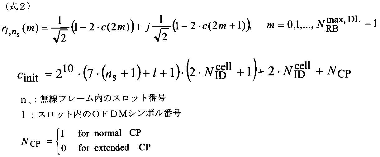
- the CSI-RS sequence r l, ns (m) is defined by the following equation (2) (Release 10 LTE).
- the pseudo-random sequence c (i) included in the equation (2) is initialized as follows (C init ).
- the initialization As can be seen from the pseudo-random sequence C init, contains different terms N ID cell by cell ID in the initialized pseudo random sequence C init.
- the pseudo-random sequence used when generating the CSI-RS sequence r l, ns (m) is also set to be different depending on the cell ID.
- the base station apparatus needs to notify the user terminal UE of the pseudo-random sequence and parameters related thereto, for example, parameters related to scrambling identification information (SCID) and cell ID as sequence information.
- SCID scrambling identification information
- Uplink reference signal information For DM-RSs for demodulating uplink PUSCH (Physical Uplink Shard Channel) signals and PUCCH (Physical Uplink Control Channel) signals, information on base sequences, offset amounts from PUCCH sequences ( Shift amount) information or cyclic shift hopping amount information is required on the user terminal side. For this reason, the base station apparatus needs to notify the user terminal UE of base sequence information, offset amount (shift amount) information from the PUCCH sequence, or cyclic shift hopping amount information as uplink reference signal information (parameter). There is.
- Radio Resource Information is information on radio resources for interference estimation used for channel quality (CQI: Channel Quality Indicator) measurement in the user terminal.
- CQI is measured at the user terminal using CSI-RS transmitted from the base station apparatus.
- CSI-RS non-zero power CSI-RS and zero power CSI-RS are defined. Non-zero power CSI-RS distributes transmission power to resources to which CSI-RS is allocated, and zero power CSI-RS does not distribute transmission power to allocated resources (CSI-RS is muted).
- CSI-RS which is a user-specific reference signal
- CSI-RS from a plurality of transmission points can be separated at the user terminal, so CSI-RS based interference measurement is promising.
- LTE Long Term Evolution
- interference from other transmission points (other cells) cannot be measured with high accuracy.
- the present applicant added a zero power CSI-RS used only for interference measurement (radio resource with a cross shown in FIG. 3).
- the interference signal can be estimated for the CQI calculation to the user terminal using the resource element (RE) in which the downlink shared data channel (PDSCH) is not transmitted.
- RE resource element
- PDSCH downlink shared data channel
- the base station apparatus needs to notify the user terminal UE of information on radio resources for interference estimation used for channel quality (CQI) measurement in the user terminal as radio resource information (parameters).
- CQI channel quality
- RRC signaling method of notifying the user terminal of information (parameters) related to the technology defined in the LTE-A system described above from the base station apparatus.
- the base station apparatus individually notifies the user terminal of information (parameters) related to the technology defined in the LTE-A system described above at the timing of the RRC Connection Reconfiguration signal. That is, the base station apparatus notifies the information using the RRC CONNECTION RECONFIGURATION signal in the processing procedure shown in FIG.
- the user terminal UE transmits a RACH preamble to the base station apparatus eNB.
- the base station apparatus eNB transmits a RACH response to the user terminal UE when receiving the RACH preamble.
- the user terminal UE transmits RRC CONNECTION REQUEST (Message 3) to the base station apparatus eNB.
- the base station apparatus eNB transmits an RRC CONNECTION SETUP (Message 4) to the user terminal UE.
- the user terminal UE When receiving the RRC CONNECTION SETUP (Message 4), the user terminal UE transmits RRC CONNECTION SETUP COMPLETE to the base station apparatus eNB.
- the base station apparatus eNB When receiving the RRC CONNECTION SETUP COMPLETE, the base station apparatus eNB transmits INITIAL UE MESSAGE to the mobility management node MME that is the upper station apparatus. Thereby, Authentication and NAS security procedure are performed between the user terminal UE and the mobility management node MME. Thereafter, the mobility management node MME transmits INITIAL CONTEXT SETUP REQUEST to the base station apparatus eNB.
- the base station apparatus eNB transmits UE CAPABILITY ENQUIRY to the user terminal UE.
- the user terminal UE transmits UE CAPABILITY INFORMATION to the base station apparatus eNB.
- the base station device eNB transmits UE CAPABILITY INFO INDICATION to the mobility management node MME.
- the base station apparatus eNB transmits SECURITY MODE COMMAND to the user terminal UE. Thereafter, the base station apparatus eNB transmits RRC CONNECTION RECONFIGURATION including information (parameters) related to the technology defined in the above-described LTE-A system to the user terminal UE. After that, as illustrated in FIG. 5, when the user terminal UE receives RRC CONNECTION RECONFIGURATION, the user terminal UE transmits RRC CONNECTION RECONFIGURATION COMP to the base station apparatus eNB. Then, the user terminal UE sets information (parameters) related to the technology defined in the LTE-A system described above.
- the base station apparatus eNB After receiving the RRC CONNECTION RECONFIGURATION COMP, the base station apparatus eNB has passed the Ambiguity period until it can be determined that the configuration of information (parameters) related to the technology defined in the LTE-A system described above has been recognized. Later, the configuration is applied.
- the base station apparatus eNB at the timing of RRC CONNECTION RECONFIGURATION, notifies the user terminal UE of information (parameters) related to the technology defined in the LTE-A system described above, and the user terminal UE These information (parameters) are set. By such a procedure, it is possible to notify the user terminal of the parameters related to the technology defined in the LTE-A system at an appropriate timing.
- FIG. 6 is an explanatory diagram of a system configuration of the wireless communication system according to the present embodiment.
- the radio communication system shown in FIG. 6 is a system including, for example, an LTE system or SUPER 3G.
- carrier aggregation in which a plurality of fundamental frequency blocks with the system band of the LTE system as a unit is integrated is used.
- this wireless communication system may be called IMT-Advanced or 4G.
- the radio communication system 1 includes radio base station devices 20A and 20B and a plurality of first and second user terminals 10A and 10B communicating with the radio base station devices 20A and 20B. It is configured.
- the radio base station devices 20 ⁇ / b> A and 20 ⁇ / b> B are connected to the higher station device 30, and the higher station device 30 is connected to the core network 40.
- the radio base station apparatuses 20A and 20B are connected to each other by wired connection or wireless connection.
- the first and second user terminals 10A and 10B can communicate with the radio base station apparatuses 20A and 20B in the cells C1 and C2.
- the upper station apparatus 30 includes, for example, an access gateway apparatus, a radio network controller (RNC), a mobility management node (MME), and the like, but is not limited thereto. Note that, between cells, control of CoMP transmission is performed by a plurality of base stations as necessary.
- RNC radio network controller
- MME mobility management node
- the first and second user terminals 10A and 10B include an LTE terminal and an LTE-A terminal. In the following, the description will proceed as the first and second user terminals unless otherwise specified. For convenience of explanation, it is assumed that the first and second user terminals 10A and 10B communicate wirelessly with the radio base station apparatuses 20A and 20B, but more generally, the mobile terminal apparatus and the fixed terminal apparatus are also used.
- the user equipment (UE) including
- OFDMA Orthogonal Frequency Division Multiple Access
- SC-FDMA Single Carrier-Frequency Division Multiple Access
- the wireless access method is not limited to this.
- OFDMA is a multi-carrier transmission scheme that performs communication by dividing a frequency band into a plurality of narrow frequency bands (subcarriers) and mapping data to each subcarrier.
- SC-FDMA is a single carrier transmission method that reduces interference between terminals by dividing a system band into bands each consisting of one or continuous resource blocks for each terminal, and a plurality of terminals using different bands. .
- the downlink communication channel includes PDSCH as a downlink data channel shared by the first and second user terminals 10A and 10B, and downlink L1 / L2 control channels (PDCCH, PCFICH, PHICH). Transmission data and higher control information are transmitted by the PDSCH. PDSCH and PUSCH scheduling information and the like are transmitted by the PDCCH. The number of OFDM symbols used for PDCCH is transmitted by PCFICH (Physical Control Format Indicator Channel). The HARQ ACK / NACK for PUSCH is transmitted by PHICH (Physical Hybrid-ARQ Indicator Channel).
- the uplink communication channel includes a PUSCH as an uplink data channel shared by each user terminal and a PUCCH that is an uplink control channel. Transmission data and higher control information are transmitted by this PUSCH. Also, downlink reception quality information (CQI), ACK / NACK, and the like are transmitted by PUCCH.
- CQI downlink reception quality information
- ACK / NACK and the like are transmitted by PUCCH.
- radio base station apparatuses 20A and 20B have the same configuration and will be described as the radio base station apparatus 20.
- first and second user terminals 10A and 10B which will be described later, have the same configuration and will be described as the user terminal 10.
- the radio base station apparatus 20 includes a transmission / reception antenna 201, an amplifier unit 202, a transmission / reception unit (notification unit) 203, a baseband signal processing unit 204, a call processing unit 205, and a transmission path interface 206.
- Transmission data transmitted from the radio base station apparatus 20 to the user terminal via the downlink is input from the higher station apparatus 30 to the baseband signal processing unit 204 via the transmission path interface 206.
- the downlink data channel signal is transmitted from the RCP layer, such as PDCP layer processing, transmission data division / combination, RLC (Radio Link Control) retransmission control transmission processing, and MAC (Medium Access).
- RCP layer such as PDCP layer processing, transmission data division / combination, RLC (Radio Link Control) retransmission control transmission processing, and MAC (Medium Access).
- Control Retransmission control, for example, HARQ transmission processing, scheduling, transmission format selection, channel coding, Inverse Fast Fourier Transform (IFFT) processing, and precoding processing are performed.
- transmission processing such as channel coding and inverse fast Fourier transform is performed on the signal of the physical downlink control channel that is the downlink control channel.
- the baseband signal processing unit 204 notifies the control information for each user terminal 10 to wirelessly communicate with the radio base station apparatus 20 to the user terminals 10 connected to the same cell through the broadcast channel.
- the information for communication in the cell includes, for example, system bandwidth in uplink or downlink, and root sequence identification information (Root Sequence) for generating a random access preamble signal in PRACH (Physical Random Access Channel). Index) etc. are included.
- the transmission / reception unit 203 converts the baseband signal output from the baseband signal processing unit 204 into a radio frequency band.
- the amplifier unit 202 amplifies the radio frequency signal subjected to frequency conversion and outputs the amplified signal to the transmission / reception antenna 201.
- the transmission / reception unit 203 constitutes reception means for receiving an uplink signal including information such as a phase difference between a plurality of cells and PMI, and transmission means for transmitting a transmission signal in coordinated multipoint.
- the transmission / reception part 203 functions also as a notification part when a radio base station apparatus notifies a CSI candidate value between cells with respect to a user terminal.
- a radio frequency signal received by the transmission / reception antenna 201 is amplified by the amplifier unit 202 and is frequency-converted by the transmission / reception unit 203 to be baseband.
- the signal is converted into a signal and input to the baseband signal processing unit 204.
- the baseband signal processing unit 204 performs FFT processing, IDFT processing, error correction decoding, MAC retransmission control reception processing, RLC layer, PDCP layer reception processing on transmission data included in the baseband signal received in the uplink I do.
- the decoded signal is transferred to the higher station apparatus 30 via the transmission path interface 206.
- the call processing unit 205 performs call processing such as communication channel setting and release, state management of the radio base station apparatus 20, and radio resource management.
- FIG. 8 is a block diagram showing a configuration of a baseband signal processing unit in the radio base station apparatus shown in FIG.
- the baseband signal processing unit 204 mainly includes a layer 1 processing unit 2041, a MAC processing unit 2042, an RLC processing unit 2043, and a generation unit 2044.
- the layer 1 processing unit 2041 mainly performs processing related to the physical layer. For example, the layer 1 processing unit 2041 performs processing such as channel decoding, discrete Fourier transform (DFT), frequency demapping, inverse fast Fourier transform, and data demodulation on a signal received on the uplink. . Further, the layer 1 processing unit 2041 performs processing such as channel coding, data modulation, frequency mapping, and inverse fast Fourier transform (IFFT) on a signal transmitted in the downlink.
- DFT discrete Fourier transform
- IFFT inverse fast Fourier transform
- the MAC processing unit 2042 performs processing such as retransmission control at the MAC layer for a signal received in the uplink, scheduling for the uplink / downlink, selection of a PUSCH / PDSCH transmission format, selection of a PUSCH / PDSCH resource block, and the like. .
- the RLC processing unit 2043 performs packet division, packet combination, retransmission control in the RLC layer, etc. on packets received on the uplink / packets transmitted on the downlink.
- the generation unit 2044 generates information (parameters) related to the technology defined in the LTE-A system. For example, the generation unit 2044 (1) downlink control channel information regarding e-PDCCH (e-PDCCH signal transmission method information, multiple position information, transmission mode information, or reference signal used for demodulation of the e-PDCCH signal) (Antenna port information), (2) cell-specific reference signal information regarding cell-specific reference signals (information on multiple positions of cell-specific reference signals, information on the number of antenna ports of cell-specific reference signals of neighboring cells, or cell-specific reference signals) (3) information on the initial pseudorandom sequence of the downlink reference signal (information on the initial pseudorandom sequence of DM-RS or CSI-RS), (4) uplink DM- Uplink reference signal information related to RS (base sequence information, offset amount information from PUCCH sequence, or cyclic shift Ing amount of information), it generates and radio resource information about the radio resources for interference estimation to be used for channel quality measurement in (5) the user terminal.
- the user terminal 10 includes a transmission / reception antenna 101, an amplifier unit 102, a transmission / reception unit (reception unit) 103, a baseband signal processing unit 104, and an application unit 105.
- a radio frequency signal received by the transmission / reception antenna 101 is amplified by the amplifier unit 102, frequency-converted by the transmission / reception unit 103, and converted into a baseband signal.
- the baseband signal is subjected to FFT processing, error correction decoding, retransmission control reception processing, and the like by the baseband signal processing unit 104.
- downlink transmission data is transferred to the application unit 105.
- the application unit 105 performs processing related to layers higher than the physical layer and the MAC layer. Also, the broadcast information in the downlink data is also transferred to the application unit 105.
- uplink transmission data is input from the application unit 105 to the baseband signal processing unit 104.
- the baseband signal processing unit 104 performs mapping processing, retransmission control (HARQ) transmission processing, channel coding, DFT processing, and IFFT processing.
- the transmission / reception unit 103 converts the baseband signal output from the baseband signal processing unit 104 into a radio frequency band. Thereafter, the amplifier unit 102 amplifies the frequency-converted radio frequency signal and transmits it from the transmission / reception antenna 101.
- the transmission / reception part 103 comprises the transmission means which transmits the information of a phase difference, the information of a connected cell, the selected PMI etc. to the radio base station apparatus eNB of multiple cells, and the receiving means which receives a downlink signal.
- FIG. 10 is a block diagram showing a configuration of a baseband signal processing unit in the user terminal shown in FIG.
- the baseband signal processing unit 104 mainly includes a layer 1 processing unit 1041, a MAC processing unit 1042, an RLC processing unit 1043, and a setting unit 1044.
- the layer 1 processing unit 1041 mainly performs processing related to the physical layer. For example, the layer 1 processing unit 1041 performs processing such as channel decoding, discrete Fourier transform (DFT), frequency demapping, inverse fast Fourier transform (IFFT), and data demodulation on a signal received on the downlink. Also, the layer 1 processing unit 1041 performs processing such as channel coding, data modulation, frequency mapping, and inverse fast Fourier transform (IFFT) on a signal transmitted on the uplink.
- DFT discrete Fourier transform
- IFFT inverse fast Fourier transform
- IFFT inverse fast Fourier transform
- the MAC processing unit 1042 performs retransmission control (HARQ) at the MAC layer on a signal received on the downlink, analysis of downlink scheduling information (specification of PDSCH transmission format, identification of PDSCH resource block), and the like. Further, the MAC processing unit 1042 performs processing such as MAC retransmission control for signals transmitted on the uplink, analysis of uplink scheduling information (specification of PUSCH transmission format, specification of PUSCH resource block), and the like.
- HARQ retransmission control
- the RLC processing unit 1043 performs packet division, packet combination, retransmission control at the RLC layer, etc. on packets received on the downlink / packets transmitted on the uplink.
- the setting unit 1044 sets information (parameters) related to the technology defined in the LTE-A system notified at the timing of RRC CONNECTION RECONFIGURATION (RRC signaling).
- This information includes (1) e-PDCCH downlink control channel information (e-PDCCH signal transmission method information, multiplexing position information, transmission mode information, or reference signal antenna port used for demodulation of the e-PDCCH signal).
- cell-specific reference signal information related to the cell-specific reference signal information on the multiplexing position of the cell-specific reference signal, information on the number of antenna ports of the cell-specific reference signal of the adjacent cell, or cell-specific reference signal
- information on the initial pseudorandom sequence of the downlink reference signal information on the initial pseudorandom sequence of DM-RS or CSI-RS
- uplink on the uplink DM-RS Reference signal information base sequence information, offset amount information from PUCCH sequence, or cyclic shift hopping amount information
- the generation unit 2044 of the base station apparatus generates information related to the technology defined in the LTE-A system.
- the base station apparatus notifies this information to the user terminal using the RRC Connection Reconfiguration signal.
- the RRC Connection Reconfiguration signal is received, and the setting unit 1044 sets information related to the technology defined in the LTE-A system.
- the base station apparatus receives the RRC CONNECTION RECONFIGURATION COMP, that is, after the Ambiguity period has elapsed until it can be determined that the configuration of the information related to the technology defined in the LTE-A system can be recognized. Apply.
Landscapes
- Engineering & Computer Science (AREA)
- Computer Networks & Wireless Communication (AREA)
- Signal Processing (AREA)
- Quality & Reliability (AREA)
- Computer Security & Cryptography (AREA)
- Mobile Radio Communication Systems (AREA)
- Radio Transmission System (AREA)
Abstract
Description
(1)拡張物理下り制御チャネル(e-PDCCH)に関する下り制御チャネル情報
(2)セル固有参照信号に関するセル固有参照信号情報
(3)下り参照信号の初期擬似ランダム系列に関する系列情報
(4)上りDM-RS(Demodulation-Reference Signal)に関する上り参照信号情報
(5)ユーザ端末におけるチャネル品質測定に用いる干渉推定用の無線リソースに関する無線リソース情報
上述したように、LTE-AシステムのMU-MIMO伝送において、複数のユーザ端末UEに対してデータ送信する際に下り制御情報をPDCCH領域に割当てる場合、下り制御情報を伝送するためのPDCCH領域が足りなくなり、PDSCH領域に多重できるユーザ端末UEの数が制限されてしまうことが考えられる。このため、サブフレームの先頭から最大3OFDMシンボルの制御領域以外にPDCCHの割当て領域を拡張することが考えられる(e-PDCCH)。
図2に示すマクロ基地局装置eNB(eNodeB)と複数の基地局装置RRH(Remote Radio Head)とにより階層的に構成されているシステムにおいては、セル固有参照信号(CRS)は、相互に干渉しないように異なる周波数リソースで送信されている。Rel-10のシステムにおいて、各基地局装置RRHは、マクロ基地局装置eNBから送信される参照信号の周波数リソースに対して、周波数領域で所定量シフトされた周波数リソースを用いてCRSを送信する。つまり、各基地局装置RRHから送信されるCRSは、マクロ基地局装置eNBのCRSに対して周波数方向にシフトされている。このシフト量Vshiftは、固有のセルID(cell ID)に基づいて決定される(Vshift=(cell ID mod 6))。基地局装置は、この情報(CRSの多重位置の情報)もセル固有参照信号情報(パラメータ)としてユーザ端末UEに通知する必要がある。
下り参照信号であるDM-RS(Demodulation-Reference Signal)又はCSI-RS(Channel State Information-Reference Signal)においては、スクランブル系列の擬似ランダム系列が以下のように定義されている。

上りリンクのPUSCH(Physical Uplink Shard Channel)信号やPUCCH(Physical Uplink Control Channel)信号を復調するためのDM-RSについては、ベースシーケンスの情報、PUCCH系列からのオフセット量(シフト量)の情報、又はサイクリックシフトホッピング量の情報がユーザ端末側で必要となる。このため、基地局装置は、ベースシーケンスの情報、PUCCH系列からのオフセット量(シフト量)の情報、又はサイクリックシフトホッピング量の情報を上り参照信号情報(パラメータ)としてユーザ端末UEに通知する必要がある。
この無線リソース情報は、ユーザ端末におけるチャネル品質(CQI:Channel Quality Indicator)測定に用いる干渉推定用の無線リソースに関する情報である。CQIは、基地局装置から送信されたCSI-RSを用いてユーザ端末で測定される。CSI-RSとしては、ノンゼロパワーCSI-RSとゼロパワーCSI-RSとが定義されている。ノンゼロパワーCSI-RSは、CSI-RSが割り当てられるリソースに送信パワーを分配し、ゼロパワーCSI-RSは、割り当てられるリソースに送信パワーが分配されない(CSI-RSがミュートされた)。
以下に、本発明の実施の形態に係る無線通信システムについて詳細に説明する。図6は、本実施の形態に係る無線通信システムのシステム構成の説明図である。なお、図6に示す無線通信システムは、例えば、LTEシステム或いは、SUPER 3Gが包含されるシステムである。この無線通信システムでは、LTEシステムのシステム帯域を一単位とする複数の基本周波数ブロックを一体としたキャリアアグリゲーションが用いられている。また、この無線通信システムは、IMT-Advancedと呼ばれても良く、4Gと呼ばれても良い。
Claims (19)
- LTE-Advancedシステムの規格に準拠して構成された基地局装置と、前記基地局装置と無線通信可能に構成されたユーザ端末と、を備えた無線通信システムであって、
拡張物理下り制御チャネルに関する下り制御チャネル情報を生成する生成部と、前記下り制御チャネル情報をRRC Connection Reconfiguration信号を用いてユーザ端末に通知する通知部と、を有する基地局装置と、
前記RRC Connection Reconfiguration信号を受信する受信部と、前記下り制御チャネル情報を設定する設定部と、を有するユーザ端末と、
を具備することを特徴とする無線通信システム。 - 前記下り制御チャネル情報は、拡張物理下り制御チャネル信号の送信方法の情報、多重位置の情報、送信モードの情報又は拡張物理下り制御チャネル信号の復調に用いる参照信号のアンテナポートの情報であることを特徴とする請求項1記載の無線通信システム。
- LTE-Advancedシステムの規格に準拠して構成された基地局装置と、前記基地局装置と無線通信可能に構成されたユーザ端末と、を備えた無線通信システムであって、
セル固有参照信号に関するセル固有参照信号情報を生成する生成部と、前記セル固有参照信号情報をRRC Connection Reconfiguration信号を用いてユーザ端末に通知する通知部と、を有する基地局装置と、
前記RRC Connection Reconfiguration信号を受信する受信部と、前記セル固有参照信号情報を設定する設定部と、を有するユーザ端末と、
を具備することを特徴とする無線通信システム。 - 前記セル固有参照信号情報は、セル固有参照信号の多重位置の情報、隣接セルのセル固有参照信号のアンテナポート数の情報、又はセル固有参照信号が存在しているサブフレームか否かの情報であることを特徴とする請求項3記載の無線通信システム。
- LTE-Advancedシステムの規格に準拠して構成された基地局装置と、前記基地局装置と無線通信可能に構成されたユーザ端末と、を備えた無線通信システムであって、
下り参照信号の初期擬似ランダム系列に関する系列情報を生成する生成部と、前記系列情報をRRC Connection Reconfiguration信号を用いてユーザ端末に通知する通知部と、を有する基地局装置と、
前記RRC Connection Reconfiguration信号を受信する受信部と、前記系列情報を設定する設定部と、を有するユーザ端末と、
を具備することを特徴とする無線通信システム。 - 前記系列情報は、DM-RS(Demodulation-Reference Signal)又はCSI-RS(Channel State Information-Reference Signal)の初期擬似ランダム系列の情報であることを特徴とする請求項5記載の無線通信システム。
- LTE-Advancedシステムの規格に準拠して構成された基地局装置と、前記基地局装置と無線通信可能に構成されたユーザ端末と、を備えた無線通信システムであって、
上りDM-RS(Demodulation-Reference Signal)に関する上り参照信号情報を生成する生成部と、前記上り参照信号情報をRRC Connection Reconfiguration信号を用いてユーザ端末に通知する通知部と、を有する基地局装置と、
前記RRC Connection Reconfiguration信号を受信する受信部と、前記上り参照信号情報を設定する設定部と、を有するユーザ端末と、
を具備することを特徴とする無線通信システム。 - 前記上り参照信号情報は、ベースシーケンスの情報、物理上り制御チャネル系列からのオフセット量の情報、又はサイクリックシフトホッピング量の情報であることを特徴とする請求項7記載の無線通信システム。
- LTE-Advancedシステムの規格に準拠して構成された基地局装置と、前記基地局装置と無線通信可能に構成されたユーザ端末と、を備えた無線通信システムであって、
前記ユーザ端末におけるチャネル品質測定に用いる干渉推定用の無線リソースに関する無線リソース情報を生成する生成部と、前記無線リソース情報をRRC Connection Reconfiguration信号を用いてユーザ端末に通知する通知部と、を有する基地局装置と、
前記RRC Connection Reconfiguration信号を受信する受信部と、前記無線リソース情報を設定する設定部と、を有するユーザ端末と、
を具備することを特徴とする無線通信システム。 - LTE-Advancedシステムの規格に準拠して構成された基地局装置と、前記基地局装置と無線通信可能に構成されたユーザ端末と、を備えた無線通信システムにおける基地局装置であって、
拡張物理下り制御チャネルに関する下り制御チャネル情報を生成する生成部と、前記下り制御チャネル情報をRRC Connection Reconfiguration信号を用いてユーザ端末に通知する通知部と、を有することを特徴とする基地局装置。 - LTE-Advancedシステムの規格に準拠して構成された基地局装置と、前記基地局装置と無線通信可能に構成されたユーザ端末と、を備えた無線通信システムにおける基地局装置であって、
セル固有参照信号に関するセル固有参照信号情報を生成する生成部と、前記セル固有参照信号情報をRRC Connection Reconfiguration信号を用いてユーザ端末に通知する通知部と、を有することを特徴とする基地局装置。 - LTE-Advancedシステムの規格に準拠して構成された基地局装置と、前記基地局装置と無線通信可能に構成されたユーザ端末と、を備えた無線通信システムにおける基地局装置であって、
下り参照信号の初期擬似ランダム系列に関する系列情報を生成する生成部と、前記系列情報をRRC Connection Reconfiguration信号を用いてユーザ端末に通知する通知部と、を有することを特徴とする基地局装置。 - LTE-Advancedシステムの規格に準拠して構成された基地局装置と、前記基地局装置と無線通信可能に構成されたユーザ端末と、を備えた無線通信システムにおける基地局装置であって、
上りDM-RS(Demodulation-Reference Signal)に関する上り参照信号情報を生成する生成部と、前記上り参照信号情報をRRC Connection Reconfiguration信号を用いてユーザ端末に通知する通知部と、を有することを特徴とする基地局装置。 - LTE-Advancedシステムの規格に準拠して構成された基地局装置と、前記基地局装置と無線通信可能に構成されたユーザ端末と、を備えた無線通信システムにおける基地局装置であって、
前記ユーザ端末におけるチャネル品質測定に用いる干渉推定用の無線リソースに関する無線リソース情報を生成する生成部と、前記無線リソース情報をRRC Connection Reconfiguration信号を用いてユーザ端末に通知する通知部と、を有することを特徴とする基地局装置。 - LTE-Advancedシステムの規格に準拠して構成された基地局装置と、前記基地局装置と無線通信可能に構成されたユーザ端末と、を備えた無線通信システムにおける無線通信方法であって、
前記基地局装置において、拡張物理下り制御チャネルに関する下り制御チャネル情報を生成するステップと、前記下り制御チャネル情報をRRC Connection Reconfiguration信号を用いてユーザ端末に通知するステップと、
前記ユーザ端末において、前記RRC Connection Reconfiguration信号を受信するステップと、前記下り制御チャネル情報設定するステップと、
を有することを特徴とする無線通信方法。 - LTE-Advancedシステムの規格に準拠して構成された基地局装置と、前記基地局装置と無線通信可能に構成されたユーザ端末と、を備えた無線通信システムにおける無線通信方法であって、
前記基地局装置において、セル固有参照信号に関するセル固有参照信号情報を生成するステップと、前記セル固有参照信号情報をRRC Connection Reconfiguration信号を用いてユーザ端末に通知するステップと、
前記ユーザ端末において、前記RRC Connection Reconfiguration信号を受信するステップと、前記セル固有参照信号情報を設定するステップと、
を有することを特徴とする無線通信方法。 - LTE-Advancedシステムの規格に準拠して構成された基地局装置と、前記基地局装置と無線通信可能に構成されたユーザ端末と、を備えた無線通信システムにおける無線通信方法であって、
前記基地局装置において、下り参照信号の初期擬似ランダム系列に関する系列情報を生成するステップと、前記系列情報をRRC Connection Reconfiguration信号を用いてユーザ端末に通知するステップと、
前記ユーザ端末において、前記RRC Connection Reconfiguration信号を受信するステップと、前記系列情報を設定するステップと、
を有することを特徴とする無線通信方法。 - LTE-Advancedシステムの規格に準拠して構成された基地局装置と、前記基地局装置と無線通信可能に構成されたユーザ端末と、を備えた無線通信システムにおける無線通信方法であって、
前記基地局装置において、上りDM-RS(Demodulation-Reference Signal)に関する上り参照信号情報を生成するステップと、前記上り参照信号情報をRRC Connection Reconfiguration信号を用いてユーザ端末に通知するステップと、
前記ユーザ端末において、前記RRC Connection Reconfiguration信号を受信するステップと、前記上り参照信号情報を設定するステップと、
を有することを特徴とする無線通信方法。 - LTE-Advancedシステムの規格に準拠して構成された基地局装置と、前記基地局装置と無線通信可能に構成されたユーザ端末と、を備えた無線通信システムにおける無線通信方法であって、
前記基地局装置において、前記ユーザ端末におけるチャネル品質測定に用いる干渉推定用の無線リソースに関する無線リソース情報を生成するステップと、前記無線リソース情報をRRC Connection Reconfiguration信号を用いてユーザ端末に通知するステップと、
前記ユーザ端末において、前記RRC Connection Reconfiguration信号を受信するステップと、前記無線リソース情報を設定するステップと、
を有することを特徴とする無線通信方法。
Priority Applications (6)
| Application Number | Priority Date | Filing Date | Title |
|---|---|---|---|
| EP13769098.8A EP2833687A4 (en) | 2012-03-30 | 2013-03-18 | WIRELESS COMMUNICATION SYSTEM, BASE STATION AND WIRELESS COMMUNICATION PROCESS |
| CA2866259A CA2866259A1 (en) | 2012-03-30 | 2013-03-18 | Radio communication system, base station apparatus and radio communication method |
| KR1020147024685A KR20140142238A (ko) | 2012-03-30 | 2013-03-18 | 무선통신시스템, 기지국장치, 및 무선통신방법 |
| CN201380018101.5A CN104247537B (zh) | 2012-03-30 | 2013-03-18 | 无线通信系统、基站装置以及无线通信方法 |
| US14/387,445 US9769809B2 (en) | 2012-03-30 | 2013-03-18 | Radio communication system, base station apparatus and radio communication method |
| RU2014142969A RU2628766C2 (ru) | 2012-03-30 | 2013-03-18 | Система радиосвязи, базовая станция и способ радиосвязи |
Applications Claiming Priority (2)
| Application Number | Priority Date | Filing Date | Title |
|---|---|---|---|
| JP2012-081303 | 2012-03-30 | ||
| JP2012081303A JP6081074B2 (ja) | 2012-03-30 | 2012-03-30 | 無線通信システム、基地局装置、及び無線通信方法 |
Publications (1)
| Publication Number | Publication Date |
|---|---|
| WO2013146434A1 true WO2013146434A1 (ja) | 2013-10-03 |
Family
ID=49259695
Family Applications (1)
| Application Number | Title | Priority Date | Filing Date |
|---|---|---|---|
| PCT/JP2013/057696 Ceased WO2013146434A1 (ja) | 2012-03-30 | 2013-03-18 | 無線通信システム、基地局装置、及び無線通信方法 |
Country Status (8)
| Country | Link |
|---|---|
| US (1) | US9769809B2 (ja) |
| EP (2) | EP3190849A1 (ja) |
| JP (1) | JP6081074B2 (ja) |
| KR (1) | KR20140142238A (ja) |
| CN (1) | CN104247537B (ja) |
| CA (1) | CA2866259A1 (ja) |
| RU (1) | RU2628766C2 (ja) |
| WO (1) | WO2013146434A1 (ja) |
Families Citing this family (10)
| Publication number | Priority date | Publication date | Assignee | Title |
|---|---|---|---|---|
| KR102210081B1 (ko) * | 2012-05-11 | 2021-02-01 | 팬텍 주식회사 | 무선통신 시스템에서의 참조신호 송수신 방법 및 장치 |
| US10958391B2 (en) | 2014-11-18 | 2021-03-23 | Qualcomm Incorporated | Tone plans for wireless communication networks |
| US10560935B2 (en) | 2015-04-03 | 2020-02-11 | Lg Electronics Inc. | Method and device for transmitting and receiving signal in wireless communication system |
| US10333680B2 (en) * | 2015-10-21 | 2019-06-25 | Lg Electronics Inc. | Method of reporting CSI in wireless communication system supporting unlicensed band and apparatus supporting the same |
| US20180254868A1 (en) * | 2015-11-27 | 2018-09-06 | Ntt Docomo, Inc. | User terminal, radio base station, and radio communication method |
| CN108886708B (zh) * | 2016-03-25 | 2022-07-05 | 株式会社Ntt都科摩 | 用户终端、无线基站以及无线通信方法 |
| EP3496482A4 (en) * | 2016-08-05 | 2020-03-25 | Mitsubishi Electric Corporation | Communication system |
| KR102659833B1 (ko) * | 2017-11-16 | 2024-04-24 | 가부시키가이샤 엔티티 도코모 | 유저단말 및 무선 통신 방법 |
| PE20201377A1 (es) * | 2017-11-16 | 2020-11-30 | Ntt Docomo Inc | Terminal de usuario y metodo de comunicacion por radio |
| CA3083145A1 (en) * | 2017-11-29 | 2019-06-06 | Guangdong Oppo Mobile Telecommunications Corp., Ltd. | Method for reestablishing rrc connection, terminal and storage medium |
Citations (1)
| Publication number | Priority date | Publication date | Assignee | Title |
|---|---|---|---|---|
| WO2011112036A2 (ko) * | 2010-03-11 | 2011-09-15 | 엘지전자 주식회사 | 제어 채널의 할당 방법 및 이를 위한 장치 |
Family Cites Families (19)
| Publication number | Priority date | Publication date | Assignee | Title |
|---|---|---|---|---|
| EP3432504B1 (en) | 2007-10-30 | 2021-06-23 | Nokia Technologies Oy | Methods, apparatuses, system and related computer program product for resource allocation |
| US20110142107A1 (en) * | 2009-06-16 | 2011-06-16 | Kyle Jung-Lin Pan | Rank Adaptive Cyclic Shift for Demodulation Reference Signal |
| KR101710204B1 (ko) * | 2009-07-28 | 2017-03-08 | 엘지전자 주식회사 | 다중 입출력 통신 시스템에서 채널측정을 위한 기준신호의 전송 방법 및 그 장치 |
| US8824384B2 (en) | 2009-12-14 | 2014-09-02 | Samsung Electronics Co., Ltd. | Systems and methods for transmitting channel quality information in wireless communication systems |
| KR101754970B1 (ko) * | 2010-01-12 | 2017-07-06 | 삼성전자주식회사 | 무선 통신 시스템의 채널 상태 측정 기준신호 처리 장치 및 방법 |
| KR101676013B1 (ko) * | 2010-05-03 | 2016-11-14 | 삼성전자주식회사 | 무선 통신 시스템에서 제어 채널을 재설정하는 방법 및 장치 |
| US9998944B2 (en) * | 2011-04-29 | 2018-06-12 | Intel Corporation | System and method of channel control in a wireless communication system |
| WO2013005986A2 (ko) * | 2011-07-04 | 2013-01-10 | 엘지전자 주식회사 | 무선 접속 시스템에서 참조 신호 송수신 방법 및 이를 위한 단말 |
| US8437303B2 (en) * | 2011-07-04 | 2013-05-07 | Ofinno Technologies, Llc | System frame number in multicarrier systems |
| US9794955B2 (en) * | 2011-08-15 | 2017-10-17 | Texas Instruments Incorporated | Configuration of CSI-RS for CoMP feedback |
| US9402264B2 (en) * | 2011-09-30 | 2016-07-26 | Intel Corporation | Methods to transport internet traffic over multiple wireless networks simultaneously |
| EP2789141A1 (en) * | 2011-12-09 | 2014-10-15 | Telefonaktiebolaget LM Ericsson (PUBL) | Initializing reference signal generation in wireless networks |
| JP2013123141A (ja) * | 2011-12-12 | 2013-06-20 | Sharp Corp | 基地局、端末、通信システムおよび通信方法 |
| US8982725B2 (en) * | 2012-02-03 | 2015-03-17 | Mediatek Inc. | Method and apparatus for collecting and providing diverse traffic information in cellular networks |
| WO2013140437A1 (ja) * | 2012-03-19 | 2013-09-26 | 富士通株式会社 | 無線通信方法、無線通信システム、無線局、及び無線端末 |
| US9258801B2 (en) * | 2012-03-19 | 2016-02-09 | Telefonaktiebolaget L M Ericsson (Publ) | Aggregation of resources in enhanced control channels |
| US20130250879A1 (en) * | 2012-03-22 | 2013-09-26 | Samsung Electronics Co., Ltd | Method and apparatus for transmission mode design for extension carrier of lte advanced |
| US9497756B2 (en) * | 2012-03-25 | 2016-11-15 | Comcast Cable Communications, Llc | Base station radio resource management |
| US8995375B2 (en) * | 2012-05-11 | 2015-03-31 | Telefonaktiebolaget L M Ericsson (Publ) | Method and apparatus for resource assignment during control channel ambiguity |
-
2012
- 2012-03-30 JP JP2012081303A patent/JP6081074B2/ja active Active
-
2013
- 2013-03-18 KR KR1020147024685A patent/KR20140142238A/ko not_active Ceased
- 2013-03-18 CN CN201380018101.5A patent/CN104247537B/zh active Active
- 2013-03-18 WO PCT/JP2013/057696 patent/WO2013146434A1/ja not_active Ceased
- 2013-03-18 US US14/387,445 patent/US9769809B2/en active Active
- 2013-03-18 EP EP17157593.9A patent/EP3190849A1/en not_active Withdrawn
- 2013-03-18 RU RU2014142969A patent/RU2628766C2/ru not_active IP Right Cessation
- 2013-03-18 CA CA2866259A patent/CA2866259A1/en not_active Abandoned
- 2013-03-18 EP EP13769098.8A patent/EP2833687A4/en not_active Withdrawn
Patent Citations (1)
| Publication number | Priority date | Publication date | Assignee | Title |
|---|---|---|---|---|
| WO2011112036A2 (ko) * | 2010-03-11 | 2011-09-15 | 엘지전자 주식회사 | 제어 채널의 할당 방법 및 이를 위한 장치 |
Non-Patent Citations (3)
| Title |
|---|
| "Feasibility Study for Evolved UTRA and UTRAN", 3GPP, TR25.912 (V7.1.0, September 2006 (2006-09-01) |
| SAMSUNG: "E-PDCCH multiplexing with PDSCH", 3GPP TSG RAN WG1 #68, R1-120189, February 2012 (2012-02-01), XP050562754 * |
| See also references of EP2833687A4 |
Also Published As
| Publication number | Publication date |
|---|---|
| KR20140142238A (ko) | 2014-12-11 |
| RU2014142969A (ru) | 2016-05-27 |
| CA2866259A1 (en) | 2013-10-03 |
| CN104247537A (zh) | 2014-12-24 |
| RU2628766C2 (ru) | 2017-08-22 |
| CN104247537B (zh) | 2018-11-06 |
| US20150029982A1 (en) | 2015-01-29 |
| US9769809B2 (en) | 2017-09-19 |
| JP2013211732A (ja) | 2013-10-10 |
| EP3190849A1 (en) | 2017-07-12 |
| EP2833687A1 (en) | 2015-02-04 |
| EP2833687A4 (en) | 2016-03-02 |
| JP6081074B2 (ja) | 2017-02-15 |
Similar Documents
| Publication | Publication Date | Title |
|---|---|---|
| US9609641B2 (en) | Radio communication method, radio communication system, radio base station and user terminal | |
| US9467271B2 (en) | Radio base station apparatus, mobile terminal apparatus and radio communication system | |
| JP5437310B2 (ja) | 無線基地局装置、移動端末装置、無線通信方法及び無線通信システム | |
| JP6081074B2 (ja) | 無線通信システム、基地局装置、及び無線通信方法 | |
| US9497650B2 (en) | Radio communication method, radio base station, user terminal, and radio communication system | |
| EP2950470A1 (en) | Wireless base station, user terminal and wireless communication method | |
| JP5959830B2 (ja) | 無線通信システム、無線基地局装置、ユーザ端末及び無線通信方法 | |
| WO2013069538A1 (ja) | 無線通信システム、無線基地局装置、ユーザ端末及び無線通信方法 | |
| JP2012080421A (ja) | 基地局装置、移動端末装置及び通信制御方法 | |
| EP2983431B1 (en) | User terminal, small base station, and communications method | |
| WO2014045755A1 (ja) | 無線通信システム、ユーザ端末、無線基地局及び無線通信方法 | |
| JP6989368B2 (ja) | 基地局、端末、及び無線通信方法 | |
| HK1190026A (en) | Wireless base station device, mobile terminal device, and wireless communication method | |
| JP2014187705A (ja) | 無線基地局装置、移動端末装置、及び無線通信システム |
Legal Events
| Date | Code | Title | Description |
|---|---|---|---|
| 121 | Ep: the epo has been informed by wipo that ep was designated in this application |
Ref document number: 13769098 Country of ref document: EP Kind code of ref document: A1 |
|
| ENP | Entry into the national phase |
Ref document number: 20147024685 Country of ref document: KR Kind code of ref document: A |
|
| ENP | Entry into the national phase |
Ref document number: 2866259 Country of ref document: CA |
|
| WWE | Wipo information: entry into national phase |
Ref document number: 14387445 Country of ref document: US |
|
| NENP | Non-entry into the national phase |
Ref country code: DE |
|
| REEP | Request for entry into the european phase |
Ref document number: 2013769098 Country of ref document: EP |
|
| WWE | Wipo information: entry into national phase |
Ref document number: 2013769098 Country of ref document: EP |
|
| ENP | Entry into the national phase |
Ref document number: 2014142969 Country of ref document: RU Kind code of ref document: A |