WO2013146450A1 - 流体圧ポンプモータ - Google Patents
流体圧ポンプモータ Download PDFInfo
- Publication number
- WO2013146450A1 WO2013146450A1 PCT/JP2013/057767 JP2013057767W WO2013146450A1 WO 2013146450 A1 WO2013146450 A1 WO 2013146450A1 JP 2013057767 W JP2013057767 W JP 2013057767W WO 2013146450 A1 WO2013146450 A1 WO 2013146450A1
- Authority
- WO
- WIPO (PCT)
- Prior art keywords
- fluid pressure
- supply
- discharge passage
- pressure pump
- motor
- Prior art date
- Legal status (The legal status is an assumption and is not a legal conclusion. Google has not performed a legal analysis and makes no representation as to the accuracy of the status listed.)
- Ceased
Links
Images






Classifications
-
- F—MECHANICAL ENGINEERING; LIGHTING; HEATING; WEAPONS; BLASTING
- F15—FLUID-PRESSURE ACTUATORS; HYDRAULICS OR PNEUMATICS IN GENERAL
- F15B—SYSTEMS ACTING BY MEANS OF FLUIDS IN GENERAL; FLUID-PRESSURE ACTUATORS, e.g. SERVOMOTORS; DETAILS OF FLUID-PRESSURE SYSTEMS, NOT OTHERWISE PROVIDED FOR
- F15B11/00—Servomotor systems without provision for follow-up action; Circuits therefor
- F15B11/02—Systems essentially incorporating special features for controlling the speed or actuating force of an output member
- F15B11/024—Systems essentially incorporating special features for controlling the speed or actuating force of an output member by means of differential connection of the servomotor lines, e.g. regenerative circuits
-
- F—MECHANICAL ENGINEERING; LIGHTING; HEATING; WEAPONS; BLASTING
- F04—POSITIVE - DISPLACEMENT MACHINES FOR LIQUIDS; PUMPS FOR LIQUIDS OR ELASTIC FLUIDS
- F04B—POSITIVE-DISPLACEMENT MACHINES FOR LIQUIDS; PUMPS
- F04B17/00—Pumps characterised by combination with, or adaptation to, specific driving engines or motors
- F04B17/03—Pumps characterised by combination with, or adaptation to, specific driving engines or motors driven by electric motors
-
- F—MECHANICAL ENGINEERING; LIGHTING; HEATING; WEAPONS; BLASTING
- F03—MACHINES OR ENGINES FOR LIQUIDS; WIND, SPRING, OR WEIGHT MOTORS; PRODUCING MECHANICAL POWER OR A REACTIVE PROPULSIVE THRUST, NOT OTHERWISE PROVIDED FOR
- F03C—POSITIVE-DISPLACEMENT ENGINES DRIVEN BY LIQUIDS
- F03C1/00—Reciprocating-piston liquid engines
- F03C1/02—Reciprocating-piston liquid engines with multiple-cylinders, characterised by the number or arrangement of cylinders
- F03C1/06—Reciprocating-piston liquid engines with multiple-cylinders, characterised by the number or arrangement of cylinders with cylinder axes generally coaxial with, or parallel or inclined to, main shaft axis
- F03C1/0636—Reciprocating-piston liquid engines with multiple-cylinders, characterised by the number or arrangement of cylinders with cylinder axes generally coaxial with, or parallel or inclined to, main shaft axis having rotary cylinder block
- F03C1/0639—Reciprocating-piston liquid engines with multiple-cylinders, characterised by the number or arrangement of cylinders with cylinder axes generally coaxial with, or parallel or inclined to, main shaft axis having rotary cylinder block having two or more sets of cylinders or pistons
-
- F—MECHANICAL ENGINEERING; LIGHTING; HEATING; WEAPONS; BLASTING
- F03—MACHINES OR ENGINES FOR LIQUIDS; WIND, SPRING, OR WEIGHT MOTORS; PRODUCING MECHANICAL POWER OR A REACTIVE PROPULSIVE THRUST, NOT OTHERWISE PROVIDED FOR
- F03C—POSITIVE-DISPLACEMENT ENGINES DRIVEN BY LIQUIDS
- F03C1/00—Reciprocating-piston liquid engines
- F03C1/02—Reciprocating-piston liquid engines with multiple-cylinders, characterised by the number or arrangement of cylinders
- F03C1/06—Reciprocating-piston liquid engines with multiple-cylinders, characterised by the number or arrangement of cylinders with cylinder axes generally coaxial with, or parallel or inclined to, main shaft axis
- F03C1/0636—Reciprocating-piston liquid engines with multiple-cylinders, characterised by the number or arrangement of cylinders with cylinder axes generally coaxial with, or parallel or inclined to, main shaft axis having rotary cylinder block
- F03C1/0644—Component parts
-
- F—MECHANICAL ENGINEERING; LIGHTING; HEATING; WEAPONS; BLASTING
- F03—MACHINES OR ENGINES FOR LIQUIDS; WIND, SPRING, OR WEIGHT MOTORS; PRODUCING MECHANICAL POWER OR A REACTIVE PROPULSIVE THRUST, NOT OTHERWISE PROVIDED FOR
- F03C—POSITIVE-DISPLACEMENT ENGINES DRIVEN BY LIQUIDS
- F03C1/00—Reciprocating-piston liquid engines
- F03C1/02—Reciprocating-piston liquid engines with multiple-cylinders, characterised by the number or arrangement of cylinders
- F03C1/06—Reciprocating-piston liquid engines with multiple-cylinders, characterised by the number or arrangement of cylinders with cylinder axes generally coaxial with, or parallel or inclined to, main shaft axis
- F03C1/0636—Reciprocating-piston liquid engines with multiple-cylinders, characterised by the number or arrangement of cylinders with cylinder axes generally coaxial with, or parallel or inclined to, main shaft axis having rotary cylinder block
- F03C1/0644—Component parts
- F03C1/0655—Valve means
-
- F—MECHANICAL ENGINEERING; LIGHTING; HEATING; WEAPONS; BLASTING
- F04—POSITIVE - DISPLACEMENT MACHINES FOR LIQUIDS; PUMPS FOR LIQUIDS OR ELASTIC FLUIDS
- F04B—POSITIVE-DISPLACEMENT MACHINES FOR LIQUIDS; PUMPS
- F04B49/00—Control, e.g. of pump delivery, or pump pressure of, or safety measures for, machines, pumps, or pumping installations, not otherwise provided for, or of interest apart from, groups F04B1/00 - F04B47/00
- F04B49/22—Control, e.g. of pump delivery, or pump pressure of, or safety measures for, machines, pumps, or pumping installations, not otherwise provided for, or of interest apart from, groups F04B1/00 - F04B47/00 by means of valves
- F04B49/225—Control, e.g. of pump delivery, or pump pressure of, or safety measures for, machines, pumps, or pumping installations, not otherwise provided for, or of interest apart from, groups F04B1/00 - F04B47/00 by means of valves with throttling valves or valves varying the pump inlet opening or the outlet opening
-
- F—MECHANICAL ENGINEERING; LIGHTING; HEATING; WEAPONS; BLASTING
- F15—FLUID-PRESSURE ACTUATORS; HYDRAULICS OR PNEUMATICS IN GENERAL
- F15B—SYSTEMS ACTING BY MEANS OF FLUIDS IN GENERAL; FLUID-PRESSURE ACTUATORS, e.g. SERVOMOTORS; DETAILS OF FLUID-PRESSURE SYSTEMS, NOT OTHERWISE PROVIDED FOR
- F15B13/00—Details of servomotor systems ; Valves for servomotor systems
- F15B13/02—Fluid distribution or supply devices characterised by their adaptation to the control of servomotors
- F15B13/04—Fluid distribution or supply devices characterised by their adaptation to the control of servomotors for use with a single servomotor
- F15B13/0401—Valve members; Fluid interconnections therefor
-
- F—MECHANICAL ENGINEERING; LIGHTING; HEATING; WEAPONS; BLASTING
- F15—FLUID-PRESSURE ACTUATORS; HYDRAULICS OR PNEUMATICS IN GENERAL
- F15B—SYSTEMS ACTING BY MEANS OF FLUIDS IN GENERAL; FLUID-PRESSURE ACTUATORS, e.g. SERVOMOTORS; DETAILS OF FLUID-PRESSURE SYSTEMS, NOT OTHERWISE PROVIDED FOR
- F15B2211/00—Circuits for servomotor systems
- F15B2211/20—Fluid pressure source, e.g. accumulator or variable axial piston pump
- F15B2211/205—Systems with pumps
- F15B2211/20507—Type of prime mover
- F15B2211/20515—Electric motor
-
- F—MECHANICAL ENGINEERING; LIGHTING; HEATING; WEAPONS; BLASTING
- F15—FLUID-PRESSURE ACTUATORS; HYDRAULICS OR PNEUMATICS IN GENERAL
- F15B—SYSTEMS ACTING BY MEANS OF FLUIDS IN GENERAL; FLUID-PRESSURE ACTUATORS, e.g. SERVOMOTORS; DETAILS OF FLUID-PRESSURE SYSTEMS, NOT OTHERWISE PROVIDED FOR
- F15B2211/00—Circuits for servomotor systems
- F15B2211/20—Fluid pressure source, e.g. accumulator or variable axial piston pump
- F15B2211/275—Control of the prime mover, e.g. hydraulic control
-
- F—MECHANICAL ENGINEERING; LIGHTING; HEATING; WEAPONS; BLASTING
- F15—FLUID-PRESSURE ACTUATORS; HYDRAULICS OR PNEUMATICS IN GENERAL
- F15B—SYSTEMS ACTING BY MEANS OF FLUIDS IN GENERAL; FLUID-PRESSURE ACTUATORS, e.g. SERVOMOTORS; DETAILS OF FLUID-PRESSURE SYSTEMS, NOT OTHERWISE PROVIDED FOR
- F15B2211/00—Circuits for servomotor systems
- F15B2211/30—Directional control
- F15B2211/315—Directional control characterised by the connections of the valve or valves in the circuit
- F15B2211/31523—Directional control characterised by the connections of the valve or valves in the circuit being connected to a pressure source and an output member
- F15B2211/31529—Directional control characterised by the connections of the valve or valves in the circuit being connected to a pressure source and an output member having a single pressure source and a single output member
Definitions
- the present invention relates to a fluid pressure pump motor including a fluid pressure pump that supplies a working fluid to a fluid pressure actuator and a fluid pressure motor that is rotationally driven by the working fluid that is recirculated from the fluid pressure actuator.
- the generator is rotated by the surplus output of the engine and the exhaust energy of the actuator, the electric power generated by the generator is stored, and the actuator is operated using the stored electric power.
- a hybrid structure that assists is used.
- an assist pump that is rotationally driven by an electric motor to discharge the working fluid and assist the operation of the actuator by the main pump, and a regenerative motor that is rotated by the working fluid returned from the actuator and rotationally drives the electric motor,
- a fluid pressure pump motor is used.
- JP2011-127569A includes an assist regenerative motor that includes a motor generator that rotates by electric energy, a regenerative motor that rotationally drives the motor generator by the energy of the working fluid, and an assist pump that is driven by the motor generator to discharge the working fluid.
- An apparatus is disclosed.
- a flow path for guiding the working fluid sucked into the assist pump from the tank, and the working fluid discharged from the regeneration motor is led to the tank.
- the flow path may be provided as a common supply / discharge passage.
- assist and regeneration are performed at the same time, such as regeneration from another actuator while assisting driving of one actuator, the working fluid is sucked into the assist pump from the supply / discharge passage, and at the same time, the regeneration motor The working fluid is discharged into the supply / discharge passage.
- the present invention has been made in view of the above problems, and even when the fluid pressure pump and the fluid pressure motor are operated simultaneously, the working fluid is stably supplied from the supply / discharge passage to the fluid pressure pump. With the goal.
- a fluid pressure pump motor comprising: a fluid pressure pump that supplies a working fluid to the fluid pressure actuator; and a fluid pressure motor that is rotationally driven by the working fluid returned from the fluid pressure actuator.
- the fluid pressure pump motor includes a supply / discharge passage through which a working fluid sucked into the fluid pressure pump flows and a working fluid discharged from the fluid pressure motor flows, and a flow path of the supply / discharge passage provided in the supply / discharge passage.
- a variable valve having an adjustable area. In the variable valve, the flow area of the supply / discharge passage when the fluid pressure pump and the fluid pressure motor are simultaneously operated is set so that only one of the fluid pressure pump and the fluid pressure motor operates. It is smaller than the channel area when it is.
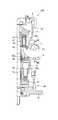
- FIG. 1 is a front sectional view of a fluid pressure pump motor according to a first embodiment of the present invention.
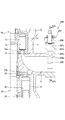
- FIG. 2A is a diagram illustrating the operation of the variable valve when the flow path area is maximum.
- 2B is a cross-sectional view taken along the line IIB-IIB in FIG. 2A.
- FIG. 3A is a diagram for explaining the operation of the variable valve when the flow path area is minimum.
- 3B is a cross-sectional view taken along the line IIIB-IIIB in FIG. 3A.
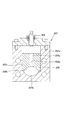
- FIG. 4A is a front sectional view of the vicinity of the variable valve of the fluid pressure pump motor according to the second embodiment of the present invention.
- 4B is a cross-sectional view taken along the line IVB-IVB in FIG. 4A.
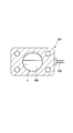
- 5A is a front sectional view of the vicinity of a variable valve of a fluid pressure pump motor according to a third embodiment of the present invention.
- 5B is a cross-sectional view taken along the line VB-VB in FIG. 5A.
- FIG. 6A is a front sectional view in the vicinity of a variable valve of a fluid pressure pump motor according to a fourth embodiment of the present invention.
- 6B is a cross-sectional view taken along the line VIB-VIB in FIG. 6A.
- a hydraulic pump motor 100 as a fluid pressure pump motor according to a first embodiment of the present invention will be described with reference to FIGS. 1 to 3B.
- hydraulic oil is used as the working fluid.
- other fluids such as working water may be used as the working fluid instead of the working oil.
- the hydraulic pump motor 100 is driven by supplying hydraulic oil to a hydraulic actuator (not shown) as a fluid pressure actuator.
- the hydraulic pump motor 100 is applied to, for example, a hybrid construction machine such as a power shovel that drives a hydraulic actuator with hydraulic oil discharged from a main hydraulic pump (not shown) driven by a prime mover.
- the hydraulic pump motor 100 includes a hydraulic pump 10 as a fluid pressure pump that supplies hydraulic oil to the hydraulic actuator, a hydraulic motor 20 as a fluid pressure motor that is rotationally driven by the hydraulic oil recirculated from the hydraulic actuator, and the hydraulic pump 10. And an electric motor 30 arranged in series with the hydraulic motor 20.
- the hydraulic pump 10 and the hydraulic motor 20 are swash plate type variable displacement type piston pump motors, respectively.
- the hydraulic motor 20 is a large piston pump motor compared to the hydraulic pump 10.
- the hydraulic pump motor 100 includes a casing 3 that houses the hydraulic pump 10 and the hydraulic motor 20, and a single rotating shaft 2 that is rotatably supported by the casing 3 and is used in common by the hydraulic pump 10 and the hydraulic motor 20. With.
- the casing 3 has a flange portion 3 a that is bolted to the plate 40.
- the casing 3 is connected to the electric motor 30 via the flange portion 3 a and the plate 40.
- a speed reducer may be provided between the rotating shaft 2 of the hydraulic pump motor 100 and the rotating shaft of the electric motor.
- the casing 3 includes a supply / discharge passage 4 through which hydraulic oil sucked into the hydraulic pump 10 flows and hydraulic oil discharged from the hydraulic motor 20 flows, a discharge passage 5 through which hydraulic oil discharged from the hydraulic pump 10 flows, and a hydraulic actuator And a return valve 6 through which hydraulic oil supplied to the hydraulic motor 20 flows and a variable valve 7 provided in the supply / discharge passage 4 and capable of adjusting the flow area of the supply / discharge passage 4.
- the supply / discharge passage 4 communicates with a tank (not shown) in which hydraulic oil is stored.
- the discharge passage 5 and the return passage 6 communicate with the hydraulic actuator.
- the supply / discharge passage 4 is provided to face the discharge passage 5 and the return passage 6.
- the variable valve 7 is a rotary valve that is driven by a rotary actuator (not shown) and can rotate around a rotary shaft 7a.
- the rotating shaft 7a is rotatably supported by the casing 3.
- the rotation angle of the variable valve 7 can be adjusted steplessly between 0 degrees and 90 degrees by the rotation of the rotating shaft 7a.
- variable valve 7 When the rotation angle is 0 degree (the state shown in FIGS. 2A and 2B), the variable valve 7 is accommodated on the wall surface of the supply / discharge passage 4 to maximize the flow area of the supply / discharge passage 4.
- the variable valve 7 protrudes into the supply / exhaust passage 4 by rotating about the rotating shaft 7a to reduce the flow area of the supply / exhaust passage 4.
- the variable valve 7 minimizes the flow area of the supply / discharge passage 4 when the rotation angle is 90 degrees (the state shown in FIGS. 3A and 3B).
- variable valve 7 maximizes the flow area of the supply / discharge passage 4 when only one of the hydraulic pump 10 and the hydraulic motor 20 is operating.
- the variable valve 7 restricts the flow area of the supply / discharge passage 4 when the hydraulic pump 10 and the hydraulic motor 20 are operating simultaneously.
- the variable valve 7 has a flow area of the supply / discharge passage 4 when only the hydraulic pump 10 and the hydraulic motor 20 operate when the hydraulic pump 10 and the hydraulic motor 20 operate simultaneously. It is smaller than the channel area when it is.
- the variable valve 7 is formed in a column shape having a D-shaped cross section in which a part of a cylinder is cut out.
- the variable valve 7 has a recess 7b (see FIG. 2B) that forms an inner peripheral surface that is substantially flush with the inner peripheral shape of the supply / discharge passage 4 when the rotation angle is 0 degree.
- variable valve 7 restricts the flow passage area of the supply / discharge passage 4 to approximately half when the rotation angle is 90 degrees.
- the variable valve 7 is formed so that the hydraulic oil can flow through the supply / discharge passage 4 even when the flow passage area of the supply / discharge passage 4 is minimized. Therefore, since the supply / discharge passage 4 is not completely blocked, when there is more hydraulic oil discharged from the hydraulic motor 20 than hydraulic oil sucked into the hydraulic pump 10, excess hydraulic oil is removed. Can lead to the tank.
- the hydraulic pump 10 and the hydraulic motor 20 are arranged to face each other in the axial direction of the rotary shaft 2 with the supply / discharge passage 4, the discharge passage 5, and the return passage 6 interposed therebetween.
- the hydraulic pump 10 sucks hydraulic oil in the supply / discharge passage 4 and discharges it to the discharge passage 5.
- the hydraulic pump 10 assists the drive of the hydraulic actuator by the main hydraulic pump with the discharged hydraulic oil.
- the hydraulic pump 10 includes a cylinder block 11 coupled to the rotary shaft 2, a plurality of pistons 13 respectively accommodated in a plurality of cylinders 12 defined in the cylinder block 11, and a swash plate that reciprocates the pistons 13 that are in sliding contact with each other. 14 and a port plate 15 in which the end face of the cylinder block 11 is in sliding contact.
- the cylinder block 11 is formed in a substantially cylindrical shape and rotates integrally with the rotary shaft 2.
- the cylinder block 11 is rotationally driven by the rotary shaft 2.
- a plurality of cylinders 12 are formed in the cylinder block 11 in parallel with the rotation shaft 2.
- the cylinders 12 are arranged in a ring at regular intervals on the same circumference around the rotation axis 2 of the cylinder block 11.
- a piston 13 is inserted into each cylinder 12, and a volume chamber 12 a is defined between the cylinders 13.
- the volume chamber 12a communicates with the port plate 15 through the communication hole.
- the piston 13 is in sliding contact with the swash plate 14 when the cylinder block 11 rotates together with the rotary shaft 2. Thereby, the piston 13 reciprocates in the cylinder 12 according to the tilt angle of the swash plate 14, and expands and contracts the volume chamber 12a.
- the swash plate 14 is provided such that the tilt angle can be adjusted by a capacity switching actuator (not shown).
- the swash plate 14 can be tilted from a state where the tilt angle perpendicular to the rotation shaft 2 is zero to the state shown in FIG. 2A.
- the tilt angle of the swash plate 14 is adjusted steplessly by the capacity switching actuator.
- the port plate 15 is formed in a disc shape, and has a through hole through which the rotary shaft 2 is inserted.
- the port plate 15 is formed in an arc shape centered on the rotation shaft 2 and is formed in an arc shape centered on the rotation shaft 2 and discharged, similarly to the supply port 15a communicating the supply / discharge passage 4 and the volume chamber 12a. It has a discharge port 15b for communicating the passage 5 and the volume chamber 12a.
- a region where the piston 13 slides on the swash plate 14 and the volume chamber 12a expands is a suction region
- a region where the piston 13 slides on the swash plate 14 and the volume chamber 12a contracts is a discharge region.
- the supply port 15a is formed corresponding to the suction area
- the discharge port 15b is formed corresponding to the discharge area.
- the hydraulic motor 20 is rotationally driven by hydraulic oil discharged from the hydraulic actuator.
- the hydraulic motor 20 includes a cylinder block 21 connected to the rotary shaft 2, a plurality of pistons 23 accommodated in a plurality of cylinders 22 defined in the cylinder block 21, and a swash plate that reciprocates the pistons 23 that are in sliding contact with each other. 24 and a port plate 25 in which the end face of the cylinder block 21 is in sliding contact.
- the cylinder block 21, the cylinder 22, the piston 23, and the swash plate 24 of the hydraulic motor 20 have the same configuration except for the configuration of the hydraulic pump 10 described above, and thus the description thereof is omitted here.
- the port plate 25 is formed in a disc shape and has a through hole through which the rotary shaft 2 is inserted.
- the port plate 25 is formed in an arc shape with the rotation shaft 2 as the center, and the supply port 25a that connects the return passage 6 and the volume chamber 22a. It has a discharge port 25b for communicating the passage 4 and the volume chamber 22a.
- a region where the piston 23 slides on the swash plate 24 and the volume chamber 22a expands is a suction region
- a region where the piston 23 slides on the swash plate 24 and the volume chamber 22a contracts is a discharge region.
- the supply port 25a is formed corresponding to the suction area
- the discharge port 25b is formed corresponding to the discharge area.
- the electric motor 30 can drive the hydraulic pump 10 to rotate and can generate regenerative power by the rotation of the hydraulic motor 20.
- the electric power generated by the electric motor 30 is stored in a power storage device (not shown).
- the electric motor 30 rotationally drives the hydraulic pump 10 using the regenerative power regenerated by the rotation of the hydraulic motor 20 and stored in the power storage device.
- the electric motor 30 rotates using the power stored in the power storage device in advance.
- the rotation shaft 2 of the hydraulic pump motor 100 is rotationally driven by the rotation of the electric motor 30.
- the hydraulic pump 10 is switched to a predetermined value in which the tilt angle of the swash plate 14 is larger than zero by the capacity switching actuator.
- the piston 13 reciprocates in the cylinder 12 as the cylinder block 11 rotates.
- the hydraulic oil from the tank is sucked into the volume chamber 12 a through the supply port 15 a of the port plate 15.
- the hydraulic oil discharged from the volume chamber 12 a is guided to the discharge passage 5 through the discharge port 15 b of the port plate 15.
- the hydraulic oil discharged from the hydraulic pump motor 100 is used for driving the hydraulic actuator, and assists the driving of the hydraulic actuator by the main hydraulic pump.
- the hydraulic motor 20 is held by the capacity switching actuator so that the tilt angle of the swash plate 24 becomes zero. Therefore, since the piston 23 does not reciprocate in the cylinder 22, the displacement volume by the piston 23 becomes zero. Accordingly, since the hydraulic motor 20 only idles without supplying or discharging the hydraulic oil, the drive loss of the hydraulic motor 20 can be suppressed.
- variable valve 7 is switched so as to maximize the flow area of the supply / discharge passage 4 as shown in FIGS. 2A and 2B. Thereby, since the pressure loss in the supply / discharge passage 4 is reduced, the suction efficiency of the hydraulic pump 10 is improved.
- the hydraulic motor 20 when regenerative electric power is generated by the hydraulic oil discharged from the hydraulic actuator, the hydraulic motor 20 is switched to a predetermined value in which the inclination angle of the swash plate 24 is larger than zero by the capacity switching actuator.
- the piston 23 reciprocates in the cylinder 22 as the cylinder block 21 rotates. Due to the reciprocating motion of the piston 23, the pressurized hydraulic fluid that has returned from the hydraulic actuator through the return passage 6 flows into the volume chamber 22 a through the supply port 25 a of the port plate 25. Then, the piston 23 reciprocates in the cylinder 22 to rotationally drive the cylinder block 21.
- the hydraulic oil that has flowed into the volume chamber 22a is discharged to the supply / discharge passage 4 through the discharge port 25b of the port plate 25 and is returned to the tank.
- the rotating shaft 2 rotates integrally with the cylinder block 21, and the rotation of the rotating shaft 2 is transmitted to the rotating shaft of the electric motor 30. Thereby, the electric motor 30 can generate regenerative power and store it in the power storage device.
- the hydraulic pump 10 is held by the displacement switching actuator so that the tilt angle of the swash plate 14 becomes zero. Therefore, since the piston 13 does not reciprocate within the cylinder 12, the displacement volume by the piston 13 becomes zero. Therefore, since the hydraulic pump 10 merely idles without supplying or discharging the hydraulic oil, the drive loss of the hydraulic pump 10 can be suppressed.
- variable valve 7 is switched so as to maximize the flow area of the supply / discharge passage 4.
- the hydraulic pump motor 100 assists the supply of hydraulic oil to the plurality of hydraulic actuators by the main hydraulic pump, the hydraulic oil is assisted to drive one hydraulic actuator and the hydraulic oil is recirculated from the other hydraulic actuators. There is. In such a case, the hydraulic pump 10 and the hydraulic motor 20 operate simultaneously.
- the hydraulic pump 10 is switched to a predetermined value in which the tilt angle of the swash plate 14 is larger than zero by the capacity switching actuator.
- the hydraulic oil discharged from the hydraulic pump motor 100 is used to drive the hydraulic actuator, and assists the driving of the hydraulic actuator by the main hydraulic pump.
- the hydraulic motor 20 is switched to a predetermined value in which the inclination angle of the swash plate 24 is larger than zero by the capacity switching actuator. As a result, the piston 23 reciprocates in the cylinder 22, the cylinder block 21 is rotationally driven, and the rotary shaft 2 that rotates integrally with the cylinder block 21 is rotationally driven.
- the energy of the electric motor 30 necessary for driving the hydraulic pump 10 can be reduced by the hydraulic motor 20 driving the rotary shaft 2 to rotate. That is, the hydraulic motor 20 assists the drive of the hydraulic pump 10 by the electric motor 30.
- the electric motor 30 is rotated using the power stored in the power storage device in advance, The rotary shaft 2 is rotationally driven in cooperation with the hydraulic motor 20.
- the hydraulic motor 20 drives the hydraulic pump 10 by rotating the rotary shaft 2, and the electric motor 30. Is driven to rotate.
- the hydraulic pump 10 assists the drive of the hydraulic actuator by the main hydraulic pump, and the regenerative power generated by the electric motor 30 can be stored in the power storage device.
- variable valve 7 is switched to reduce the flow area of the supply / discharge passage 4.
- the hydraulic pump 10 is a variable displacement pump whose capacity changes depending on the tilt angle of the swash plate 14. Therefore, the variable valve 7 adjusts the flow area of the supply / discharge passage 4 according to the change in the suction capacity of the hydraulic pump 10.
- the variable valve 7 adjusts the flow area of the supply / exhaust passage 4 according to the rotational speed of the hydraulic pump 10.
- variable valve 7 restricts the flow area of the supply / discharge passage 4. Therefore, even the hydraulic fluid having the suction capacity required by the hydraulic pump 10 can be prevented from being discharged from the supply / discharge passage 4. Therefore, even when the hydraulic pump 10 and the hydraulic motor 20 operate simultaneously, the hydraulic oil can be stably supplied from the supply / discharge passage 4 to the hydraulic pump 10.
- variable valve 7 maximizes the flow area of the supply / discharge passage 4. Thereby, since the pressure loss in the supply / discharge passage 4 is reduced, the suction efficiency of the hydraulic pump 10 is improved. Similarly, when the hydraulic motor 20 operates alone, the variable valve 7 maximizes the flow area of the supply / discharge passage 4. Thereby, since the pressure loss in the supply / discharge passage 4 is reduced, the discharge efficiency of the hydraulic motor 20 is improved.
- FIGS. 4A and 4B a hydraulic pump motor 200 as a fluid pressure pump motor according to a second embodiment of the present invention will be described with reference to FIGS. 4A and 4B.
- the same components as those in the first embodiment described above are denoted by the same reference numerals, and redundant description will be omitted as appropriate.
- the second embodiment is different from the first embodiment in that the variable valve 207 is a gate valve.
- the hydraulic pump motor 200 is arranged in series with the hydraulic pump 10 that supplies hydraulic oil to the hydraulic actuator, the hydraulic motor 20 that is rotationally driven by the hydraulic oil that is recirculated from the hydraulic actuator, and the hydraulic pump 10 and the hydraulic motor 20.
- variable valve 207 is provided with a casing 207 a, a gate 208 that can move in the radial direction of the supply / discharge passage 4, and a threaded engagement with the gate 208. 209.
- the casing 207a is formed in a rectangular frame shape and attached to the casing 3.
- the casing 207a has a through hole 207b that communicates with the supply / discharge passage 4 of the casing 3, and a guide portion 207c that guides the gate 208 in a slidable manner.
- the through hole 207 b constitutes a part of the supply / discharge passage 4.
- the gate 208 is a block that can be translated along the guide portion 207c.
- the gate 208 includes a female screw 208a screwed with the male screw 209a of the shaft 209, and a circular arc portion 208b having the same shape as the wall surface of the supply / discharge passage 4 together with the through hole 207b when the area of the supply / discharge passage 4 is maximized. Have.
- the gate 208 is accommodated on the wall surface of the supply / discharge passage 4 when the flow passage area of the supply / discharge passage 4 is maximum.
- the gate 208 enters the supply / discharge passage 4 to reduce the flow area of the supply / discharge passage 4.
- the shaft 209 is attached to the casing 207a so as to be rotatable around the central axis.
- the shaft 209 is rotationally driven by a rotary actuator (not shown).
- the shaft 209 has a male screw 209 a that engages with the female screw 208 a of the gate 208.
- the gate 208 advances and retreats with respect to the supply / discharge passage 4 by the screwing of the male screw 209a and the female screw 208a.
- the gate 208 can be advanced and retracted to adjust the flow area of the supply / discharge passage 4.
- the variable valve 207 maximizes the flow area of the supply / discharge passage 4 when only one of the hydraulic pump 10 and the hydraulic motor 20 is operating.
- the variable valve 207 restricts the flow area of the supply / discharge passage 4 when the hydraulic pump 10 and the hydraulic motor 20 are operating simultaneously.
- the variable valve 207 has a flow area of the supply / discharge passage 4 when only the hydraulic pump 10 and the hydraulic motor 20 are operated. It is smaller than the channel area when it is.
- variable valve 207 restricts the flow area of the supply / discharge passage 4. Therefore, even the hydraulic fluid having the suction capacity required by the hydraulic pump 10 can be prevented from being discharged from the supply / discharge passage 4. Therefore, even when the hydraulic pump 10 and the hydraulic motor 20 operate simultaneously, the hydraulic oil can be stably supplied from the supply / discharge passage 4 to the hydraulic pump 10.
- variable valve 207 maximizes the flow area of the supply / discharge passage 4. Thereby, since the pressure loss in the supply / discharge passage 4 is reduced, the suction efficiency of the hydraulic pump 10 is improved. Similarly, when the hydraulic motor 20 operates alone, the variable valve 207 maximizes the flow area of the supply / discharge passage 4. Thereby, since the pressure loss in the supply / discharge passage 4 is reduced, the discharge efficiency of the hydraulic motor 20 is improved.
- variable valve 307 is a butterfly valve.
- the hydraulic pump motor 300 is arranged in series with the hydraulic pump 10 that supplies hydraulic oil to the hydraulic actuator, the hydraulic motor 20 that is rotationally driven by the hydraulic oil returned from the hydraulic actuator, and the hydraulic pump 10 and the hydraulic motor 20.
- variable valve 307 is a butterfly valve that is provided in the supply / discharge passage 4 and has a disc-shaped valve body 309 that rotates about the valve shaft 308.
- the valve shaft 308 is attached to the casing 3 so as to be rotatable around the central axis.
- the valve shaft 308 is inserted so as to pass through the center of the supply / discharge passage 4.
- the valve shaft 308 is rotationally driven by a rotary actuator (not shown).
- the valve body 309 is formed to have substantially the same diameter as the inner diameter of the supply / discharge passage 4.
- the valve body 309 rotates integrally with the valve shaft 308.
- the valve body 309 rotates when the valve shaft 308 is rotationally driven by the actuator.
- the valve body 309 maximizes the flow path area when parallel to the flow direction of the hydraulic oil in the supply / discharge passage 4.
- the valve body 309 is rotated approximately 30 ° from a state parallel to the flow direction of the hydraulic oil in the supply / exhaust passage 4, the flow passage area is reduced to approximately half.
- variable valve 307 is formed so that the hydraulic oil can flow through the supply / discharge passage 4 even when the flow passage area of the supply / discharge passage 4 is minimized. Therefore, since the supply / discharge passage 4 is not completely blocked, when there is more hydraulic oil discharged from the hydraulic motor 20 than hydraulic oil sucked into the hydraulic pump 10, excess hydraulic oil is removed. Can lead to the tank.
- the variable valve 307 maximizes the flow area of the supply / discharge passage 4 when only one of the hydraulic pump 10 and the hydraulic motor 20 is operating.
- the variable valve 307 restricts the flow area of the supply / discharge passage 4 when the hydraulic pump 10 and the hydraulic motor 20 are operating simultaneously.
- the variable valve 307 has a flow area of the supply / exhaust passage 4 when the hydraulic pump 10 and the hydraulic motor 20 are simultaneously operated, and only one of the hydraulic pump 10 and the hydraulic motor 20 is operated. It is smaller than the channel area when it is.
- variable valve 307 restricts the flow area of the supply / discharge passage 4. Therefore, even the hydraulic fluid having the suction capacity required by the hydraulic pump 10 can be prevented from being discharged from the supply / discharge passage 4. Therefore, even when the hydraulic pump 10 and the hydraulic motor 20 operate simultaneously, the hydraulic oil can be stably supplied from the supply / discharge passage 4 to the hydraulic pump 10.
- variable valve 307 maximizes the flow area of the supply / discharge passage 4. Thereby, since the pressure loss in the supply / discharge passage 4 is reduced, the suction efficiency of the hydraulic pump 10 is improved. Similarly, when the hydraulic motor 20 operates alone, the variable valve 307 maximizes the flow area of the supply / discharge passage 4. Thereby, since the pressure loss in the supply / discharge passage 4 is reduced, the discharge efficiency of the hydraulic motor 20 is improved.
- variable valve 407 is a spool valve.
- the hydraulic pump motor 400 is arranged in series with the hydraulic pump 10 that supplies hydraulic oil to the hydraulic actuator, the hydraulic motor 20 that is rotationally driven by the hydraulic oil that is recirculated from the hydraulic actuator, and the hydraulic pump 10 and the hydraulic motor 20. And a variable valve 407 provided in the casing 3 and capable of adjusting the flow area of the supply / discharge passage 4.
- the variable valve 407 includes a casing 407 a, a spool 408 that is movable in the radial direction of the supply / discharge passage 4, a back pressure chamber 408 a that urges the spool 408 into the supply / discharge passage 4 by supplied hydraulic oil, and a spool 408. Is a spool valve having a return spring 409 that biases the pressure toward the back pressure chamber 408a.
- the casing 407 a is formed in a substantially rectangular parallelepiped shape and is attached to the casing 3.
- the casing 407 a has a through hole 407 b communicating with the supply / discharge passage 4 of the casing 3 and a spool hole 407 c in which the spool 408 is slidably disposed in the axial direction.
- the through hole 407 b constitutes a part of the supply / discharge passage 4.
- the spool 408 is a cylinder that can advance and retreat in the spool hole 407c.
- the spool 408 maximizes the flow area of the supply / discharge passage 4 while being accommodated in the wall surface of the supply / discharge passage 4.
- the back pressure chamber 408a is defined in the spool hole 407c when the spool 408 is accommodated.
- the back pressure chamber 408a communicates with an external hydraulic source via a communication hole 407d. Hydraulic fluid is supplied to the back pressure chamber 408a from an external hydraulic source.
- the spool 408 is biased in a direction to reduce the opening area of the through hole 407b by the pressure of the hydraulic oil supplied to the back pressure chamber 408a.
- the return spring 409 is accommodated in the spool hole 407c.
- the return spring 409 is provided so as to face the back pressure chamber 408a with the spool 408 interposed therebetween.
- the return spring 409 pushes the spool 408 back toward the back pressure chamber 408a when the biasing force overcomes the pressure of the hydraulic oil in the back pressure chamber 408a.
- variable valve 407 can adjust the opening area of the supply / discharge passage 4.
- the variable valve 407 maximizes the flow area of the supply / discharge passage 4 when only one of the hydraulic pump 10 and the hydraulic motor 20 is operating.
- the variable valve 407 restricts the flow area of the supply / discharge passage 4 when the hydraulic pump 10 and the hydraulic motor 20 are operating simultaneously.
- the variable valve 407 has a flow passage area of the supply / discharge passage 4 when only the hydraulic pump 10 and the hydraulic motor 20 operate when the hydraulic pump 10 and the hydraulic motor 20 operate simultaneously. It is smaller than the channel area when it is.
- variable valve 407 reduces the flow area of the supply / discharge passage 4. Therefore, even the hydraulic fluid having the suction capacity required by the hydraulic pump 10 can be prevented from being discharged from the supply / discharge passage 4. Therefore, even when the hydraulic pump 10 and the hydraulic motor 20 operate simultaneously, the hydraulic oil can be stably supplied from the supply / discharge passage 4 to the hydraulic pump 10.
- variable valve 407 maximizes the flow area of the supply / discharge passage 4.
- the suction efficiency of the hydraulic pump 10 is improved.
- the variable valve 407 maximizes the flow area of the supply / discharge passage 4.
- the hydraulic pump motors 100, 200, 300, and 400 assist the driving of the hydraulic actuator by the main hydraulic pump, but instead, only the hydraulic pump motors 100, 200, 300, and 400 are used for hydraulic pressure. It is good also as a structure which drives an actuator.
- both the hydraulic pump 10 and the hydraulic motor 20 are swash plate type piston pump motors, but other types may be used.
Landscapes
- Engineering & Computer Science (AREA)
- Mechanical Engineering (AREA)
- General Engineering & Computer Science (AREA)
- Chemical & Material Sciences (AREA)
- Combustion & Propulsion (AREA)
- Physics & Mathematics (AREA)
- Fluid Mechanics (AREA)
- Reciprocating Pumps (AREA)
- Fluid-Driven Valves (AREA)
- Lift Valve (AREA)
- Sliding Valves (AREA)
- Details Of Reciprocating Pumps (AREA)
- Hydraulic Motors (AREA)
- Fluid-Pressure Circuits (AREA)
- Control Of Fluid Gearings (AREA)
- Operation Control Of Excavators (AREA)
Abstract
Description
以下、図1から図3Bを参照して、本発明の第一の実施の形態に係る流体圧ポンプモータとしての油圧ポンプモータ100について説明する。油圧ポンプモータ100では、作動流体として作動油が用いられる。なお、作動油に代えて、作動水など他の流体を作動流体として用いてもよい。
以下、図4A及び図4Bを参照して、本発明の第二の実施の形態に係る流体圧ポンプモータとしての油圧ポンプモータ200について説明する。なお、以下に示す各実施の形態では、前述した第一の実施の形態と同様の構成には同一の符号を付し、重複する説明は適宜省略する。
以下、図5A及び図5Bを参照して、本発明の第三の実施の形態に係る流体圧ポンプモータとしての油圧ポンプモータ300について説明する。
以下、図6A及び図6Bを参照して、本発明の第四の実施の形態に係る流体圧ポンプモータとしての油圧ポンプモータ400について説明する。
Claims (9)
- 流体圧アクチュエータに作動流体を供給する流体圧ポンプと、前記流体圧アクチュエータから還流される作動流体によって回転駆動される流体圧モータと、を備える流体圧ポンプモータであって、
前記流体圧ポンプに吸い込まれる作動流体が流れるとともに、前記流体圧モータから排出される作動流体が流れる給排通路と、
前記給排通路に設けられ、当該給排通路の流路面積を調整可能な可変バルブと、を備え、
前記可変バルブは、前記流体圧ポンプと前記流体圧モータとが同時に作動しているときの前記給排通路の流路面積を、前記流体圧ポンプ及び前記流体圧モータのいずれか一方のみが作動しているときの流路面積と比較して小さくする流体圧ポンプモータ。 - 請求項1に記載の流体圧ポンプモータであって、
前記流体圧モータの回転によって回生電力を発電するとともに、その回生電力を使用して前記流体圧ポンプを回転駆動する電動機を更に備える流体圧ポンプモータ。 - 請求項1又は2に記載の流体圧ポンプモータであって、
前記流体圧ポンプは、可変容量型のポンプであり、
前記可変バルブは、前記流体圧ポンプの吸込容量に応じて前記給排通路の流路面積を調整する流体圧ポンプモータ。 - 請求項1又は2に記載の流体圧ポンプモータであって、
前記流体圧ポンプは、固定容量型のポンプであり、
前記可変バルブは、前記流体圧ポンプの回転数に応じて前記給排通路の流路面積を調整する流体圧ポンプモータ。 - 請求項1から4のいずれか一つに記載の流体圧ポンプモータであって、
原動機で駆動されるメイン流体圧ポンプから吐出される作動流体によって前記流体圧アクチュエータを駆動するハイブリッド建設機械に適用され、
前記流体圧モータは、前記流体圧アクチュエータから排出された作動流体によって回転駆動され、
前記流体圧ポンプは、吐出した作動流体によって前記メイン流体圧ポンプによる前記流体圧アクチュエータの駆動をアシストする流体圧ポンプモータ。 - 請求項1から5のいずれか一つに記載の流体圧ポンプモータであって、
前記可変バルブは、前記給排通路の壁面に収容された状態で前記給排通路の流路面積を最大とし、回転軸を中心に回動することによって前記給排通路内に突出して前記給排通路の流路面積を小さくすることが可能なロータリバルブである流体圧ポンプモータ。 - 請求項1から5のいずれか一つに記載の流体圧ポンプモータであって、
前記可変バルブは、前記給排通路の壁面に収容された状態で前記給排通路の流路面積を最大とし前記給排通路の径方向に移動可能なゲートと、前記ゲートと螺合して設けられ、その回転によって前記ゲートを前記給排通路に対して進退させるシャフトと、を有するゲートバルブである流体圧ポンプモータ。 - 請求項1から5のいずれか一つに記載の流体圧ポンプモータであって、
前記可変バルブは、前記給排通路内に設けられ、弁軸を中心に回動することによって前記給排通路の流路面積を調整可能なバタフライバルブである流体圧ポンプモータ。 - 請求項1から5のいずれか一つに記載の流体圧ポンプモータであって、
前記可変バルブは、前記給排通路の壁面に収容された状態で前記給排通路の流路面積を最大とし前記給排通路の径方向に移動可能なスプールと、供給される作動油によって前記スプールを前記給排通路内に付勢する背圧室と、前記スプールを前記背圧室に向けて付勢する戻しばねと、を有するスプールバルブである流体圧ポンプモータ。
Priority Applications (5)
| Application Number | Priority Date | Filing Date | Title |
|---|---|---|---|
| JP2014507744A JP5608833B2 (ja) | 2012-03-26 | 2013-03-19 | 流体圧ポンプモータ |
| EP13769394.1A EP2832999B1 (en) | 2012-03-26 | 2013-03-19 | Hydraulic pump motor |
| KR1020147016294A KR101429874B1 (ko) | 2012-03-26 | 2013-03-19 | 유체압 펌프 모터 |
| US14/376,433 US9027338B2 (en) | 2012-03-26 | 2013-03-19 | Fluid pressure pump motor |
| CN201380004222.4A CN103998784B (zh) | 2012-03-26 | 2013-03-19 | 流体压泵马达 |
Applications Claiming Priority (2)
| Application Number | Priority Date | Filing Date | Title |
|---|---|---|---|
| JP2012069018 | 2012-03-26 | ||
| JP2012-069018 | 2012-03-26 |
Publications (1)
| Publication Number | Publication Date |
|---|---|
| WO2013146450A1 true WO2013146450A1 (ja) | 2013-10-03 |
Family
ID=49259708
Family Applications (1)
| Application Number | Title | Priority Date | Filing Date |
|---|---|---|---|
| PCT/JP2013/057767 Ceased WO2013146450A1 (ja) | 2012-03-26 | 2013-03-19 | 流体圧ポンプモータ |
Country Status (6)
| Country | Link |
|---|---|
| US (1) | US9027338B2 (ja) |
| EP (1) | EP2832999B1 (ja) |
| JP (1) | JP5608833B2 (ja) |
| KR (1) | KR101429874B1 (ja) |
| CN (1) | CN103998784B (ja) |
| WO (1) | WO2013146450A1 (ja) |
Families Citing this family (3)
| Publication number | Priority date | Publication date | Assignee | Title |
|---|---|---|---|---|
| JP5934543B2 (ja) * | 2012-03-29 | 2016-06-15 | Kyb株式会社 | 流体圧駆動ユニット |
| JP5767996B2 (ja) * | 2012-03-29 | 2015-08-26 | カヤバ工業株式会社 | 流体圧駆動ユニット |
| JP6084264B1 (ja) * | 2015-09-28 | 2017-02-22 | Kyb株式会社 | スプール弁装置 |
Citations (3)
| Publication number | Priority date | Publication date | Assignee | Title |
|---|---|---|---|---|
| JPS6412080A (en) * | 1988-03-10 | 1989-01-17 | Honda Motor Co Ltd | Swash plate type hydraulic device |
| JP2002048215A (ja) * | 2000-08-01 | 2002-02-15 | Honda Motor Co Ltd | 静油圧式無段変速機 |
| JP2011127569A (ja) | 2009-12-21 | 2011-06-30 | Kyb Co Ltd | アシスト回生装置 |
Family Cites Families (9)
| Publication number | Priority date | Publication date | Assignee | Title |
|---|---|---|---|---|
| US5800134A (en) * | 1994-10-24 | 1998-09-01 | Kawasaki Jukogyo Kabushiki Kaisha | Tandem, swash plate pump having drive force take-out mechanism |
| JP4179465B2 (ja) * | 2002-07-31 | 2008-11-12 | 株式会社小松製作所 | 建設機械 |
| US7021904B2 (en) * | 2003-09-29 | 2006-04-04 | Kayaba Industry Co., Ltd. | Swash plate type hydraulic pump or motor |
| US7249457B2 (en) * | 2005-02-18 | 2007-07-31 | Timberjack Inc. | Hydraulic gravitational load energy recuperation |
| JP4907231B2 (ja) * | 2006-06-06 | 2012-03-28 | カヤバ工業株式会社 | エネルギー回生型動力装置 |
| JP5225597B2 (ja) | 2007-03-16 | 2013-07-03 | カヤバ工業株式会社 | 対向式斜板型ピストンポンプ・モータ |
| US8186154B2 (en) * | 2008-10-31 | 2012-05-29 | Caterpillar Inc. | Rotary flow control valve with energy recovery |
| JP5343037B2 (ja) * | 2010-05-17 | 2013-11-13 | 株式会社 神崎高級工機製作所 | 斜板式液圧機械及び静油圧伝動装置 |
| DE112011102155B4 (de) * | 2010-08-26 | 2015-02-12 | Komatsu Ltd. | Hydraulische Axialpumpe oder hydraulischer Axialmotor mit einer Vorrichtung zur Reduktion von Druckpulsationen |
-
2013
- 2013-03-19 EP EP13769394.1A patent/EP2832999B1/en active Active
- 2013-03-19 KR KR1020147016294A patent/KR101429874B1/ko not_active Expired - Fee Related
- 2013-03-19 JP JP2014507744A patent/JP5608833B2/ja active Active
- 2013-03-19 CN CN201380004222.4A patent/CN103998784B/zh active Active
- 2013-03-19 WO PCT/JP2013/057767 patent/WO2013146450A1/ja not_active Ceased
- 2013-03-19 US US14/376,433 patent/US9027338B2/en active Active
Patent Citations (3)
| Publication number | Priority date | Publication date | Assignee | Title |
|---|---|---|---|---|
| JPS6412080A (en) * | 1988-03-10 | 1989-01-17 | Honda Motor Co Ltd | Swash plate type hydraulic device |
| JP2002048215A (ja) * | 2000-08-01 | 2002-02-15 | Honda Motor Co Ltd | 静油圧式無段変速機 |
| JP2011127569A (ja) | 2009-12-21 | 2011-06-30 | Kyb Co Ltd | アシスト回生装置 |
Non-Patent Citations (1)
| Title |
|---|
| See also references of EP2832999A4 |
Also Published As
| Publication number | Publication date |
|---|---|
| KR20140078772A (ko) | 2014-06-25 |
| US9027338B2 (en) | 2015-05-12 |
| EP2832999B1 (en) | 2016-06-01 |
| EP2832999A4 (en) | 2015-04-08 |
| EP2832999A1 (en) | 2015-02-04 |
| CN103998784A (zh) | 2014-08-20 |
| JP5608833B2 (ja) | 2014-10-15 |
| US20150040551A1 (en) | 2015-02-12 |
| KR101429874B1 (ko) | 2014-08-12 |
| CN103998784B (zh) | 2015-08-05 |
| JPWO2013146450A1 (ja) | 2015-12-10 |
Similar Documents
| Publication | Publication Date | Title |
|---|---|---|
| JP5934543B2 (ja) | 流体圧駆動ユニット | |
| JP5767996B2 (ja) | 流体圧駆動ユニット | |
| CN101743400B (zh) | 串联活塞泵 | |
| CN103930673B (zh) | 斜板式活塞泵 | |
| JP5608833B2 (ja) | 流体圧ポンプモータ | |
| KR20150121221A (ko) | 2개 이상의 부재로 형성된 스크류 펌프 | |
| CN100455800C (zh) | 阀板以及具备阀板的液压装置 | |
| CN1303330C (zh) | 缸体驱动系统及其能量再生方法 | |
| US8562307B2 (en) | Pump equipment | |
| CN111749864B (zh) | 斜板、斜板式泵以及施工机械 | |
| JP2013228036A (ja) | 流体圧アクチュエータ | |
| JP4056596B2 (ja) | 液圧源装置を使用した液圧システム | |
| WO2021020217A1 (ja) | 油圧ポンプ及び油圧装置 | |
| JP7112280B2 (ja) | ポンプユニット | |
| US9140244B2 (en) | Piston pump with cam actuated valves | |
| KR102706474B1 (ko) | 가변 유압펌프 | |
| JP6509658B2 (ja) | 可変容量型液圧回転機 | |
| JP5628134B2 (ja) | 油圧閉回路システム | |
| KR20210033768A (ko) | 밸브가 없는 유압서보 실린더 장치 | |
| JP2006214356A (ja) | 多段ピストン式の固定容量アキシャルピストンポンプ・モータ | |
| JP2013068133A (ja) | 可変容量傾斜板ピストンポンプ |
Legal Events
| Date | Code | Title | Description |
|---|---|---|---|
| 121 | Ep: the epo has been informed by wipo that ep was designated in this application |
Ref document number: 13769394 Country of ref document: EP Kind code of ref document: A1 |
|
| ENP | Entry into the national phase |
Ref document number: 2014507744 Country of ref document: JP Kind code of ref document: A |
|
| ENP | Entry into the national phase |
Ref document number: 20147016294 Country of ref document: KR Kind code of ref document: A |
|
| WWE | Wipo information: entry into national phase |
Ref document number: 14376433 Country of ref document: US |
|
| WWE | Wipo information: entry into national phase |
Ref document number: 2013769394 Country of ref document: EP |
|
| NENP | Non-entry into the national phase |
Ref country code: DE |