WO2013146547A1 - 車両用シート - Google Patents
車両用シート Download PDFInfo
- Publication number
- WO2013146547A1 WO2013146547A1 PCT/JP2013/058131 JP2013058131W WO2013146547A1 WO 2013146547 A1 WO2013146547 A1 WO 2013146547A1 JP 2013058131 W JP2013058131 W JP 2013058131W WO 2013146547 A1 WO2013146547 A1 WO 2013146547A1
- Authority
- WO
- WIPO (PCT)
- Prior art keywords
- seat cushion
- cushion frame
- frame
- rear end
- connecting member
- Prior art date
- Legal status (The legal status is an assumption and is not a legal conclusion. Google has not performed a legal analysis and makes no representation as to the accuracy of the status listed.)
- Ceased
Links
Images









Classifications
-
- B—PERFORMING OPERATIONS; TRANSPORTING
- B60—VEHICLES IN GENERAL
- B60N—SEATS SPECIALLY ADAPTED FOR VEHICLES; VEHICLE PASSENGER ACCOMMODATION NOT OTHERWISE PROVIDED FOR
- B60N2/00—Seats specially adapted for vehicles; Arrangement or mounting of seats in vehicles
- B60N2/02—Seats specially adapted for vehicles; Arrangement or mounting of seats in vehicles the seat or part thereof being movable, e.g. adjustable
- B60N2/04—Seats specially adapted for vehicles; Arrangement or mounting of seats in vehicles the seat or part thereof being movable, e.g. adjustable the whole seat being movable
- B60N2/16—Seats specially adapted for vehicles; Arrangement or mounting of seats in vehicles the seat or part thereof being movable, e.g. adjustable the whole seat being movable height-adjustable
- B60N2/1605—Seats specially adapted for vehicles; Arrangement or mounting of seats in vehicles the seat or part thereof being movable, e.g. adjustable the whole seat being movable height-adjustable characterised by the cinematic
- B60N2/161—Rods
- B60N2/1615—Parallelogram-like structure
-
- B—PERFORMING OPERATIONS; TRANSPORTING
- B60—VEHICLES IN GENERAL
- B60N—SEATS SPECIALLY ADAPTED FOR VEHICLES; VEHICLE PASSENGER ACCOMMODATION NOT OTHERWISE PROVIDED FOR
- B60N2/00—Seats specially adapted for vehicles; Arrangement or mounting of seats in vehicles
- B60N2/02—Seats specially adapted for vehicles; Arrangement or mounting of seats in vehicles the seat or part thereof being movable, e.g. adjustable
- B60N2/04—Seats specially adapted for vehicles; Arrangement or mounting of seats in vehicles the seat or part thereof being movable, e.g. adjustable the whole seat being movable
- B60N2/16—Seats specially adapted for vehicles; Arrangement or mounting of seats in vehicles the seat or part thereof being movable, e.g. adjustable the whole seat being movable height-adjustable
- B60N2/1635—Seats specially adapted for vehicles; Arrangement or mounting of seats in vehicles the seat or part thereof being movable, e.g. adjustable the whole seat being movable height-adjustable characterised by the drive mechanism
- B60N2/165—Gear wheel driven mechanism
-
- B—PERFORMING OPERATIONS; TRANSPORTING
- B60—VEHICLES IN GENERAL
- B60N—SEATS SPECIALLY ADAPTED FOR VEHICLES; VEHICLE PASSENGER ACCOMMODATION NOT OTHERWISE PROVIDED FOR
- B60N2/00—Seats specially adapted for vehicles; Arrangement or mounting of seats in vehicles
- B60N2/02—Seats specially adapted for vehicles; Arrangement or mounting of seats in vehicles the seat or part thereof being movable, e.g. adjustable
- B60N2/22—Seats specially adapted for vehicles; Arrangement or mounting of seats in vehicles the seat or part thereof being movable, e.g. adjustable the back-rest being adjustable
- B60N2/235—Seats specially adapted for vehicles; Arrangement or mounting of seats in vehicles the seat or part thereof being movable, e.g. adjustable the back-rest being adjustable by gear-pawl type mechanisms
- B60N2/2356—Seats specially adapted for vehicles; Arrangement or mounting of seats in vehicles the seat or part thereof being movable, e.g. adjustable the back-rest being adjustable by gear-pawl type mechanisms with internal pawls
- B60N2/236—Seats specially adapted for vehicles; Arrangement or mounting of seats in vehicles the seat or part thereof being movable, e.g. adjustable the back-rest being adjustable by gear-pawl type mechanisms with internal pawls linearly movable
-
- B—PERFORMING OPERATIONS; TRANSPORTING
- B60—VEHICLES IN GENERAL
- B60N—SEATS SPECIALLY ADAPTED FOR VEHICLES; VEHICLE PASSENGER ACCOMMODATION NOT OTHERWISE PROVIDED FOR
- B60N2/00—Seats specially adapted for vehicles; Arrangement or mounting of seats in vehicles
- B60N2/68—Seat frames
-
- B—PERFORMING OPERATIONS; TRANSPORTING
- B60—VEHICLES IN GENERAL
- B60N—SEATS SPECIALLY ADAPTED FOR VEHICLES; VEHICLE PASSENGER ACCOMMODATION NOT OTHERWISE PROVIDED FOR
- B60N2/00—Seats specially adapted for vehicles; Arrangement or mounting of seats in vehicles
- B60N2/68—Seat frames
- B60N2/682—Joining means
-
- B—PERFORMING OPERATIONS; TRANSPORTING
- B60—VEHICLES IN GENERAL
- B60N—SEATS SPECIALLY ADAPTED FOR VEHICLES; VEHICLE PASSENGER ACCOMMODATION NOT OTHERWISE PROVIDED FOR
- B60N2/00—Seats specially adapted for vehicles; Arrangement or mounting of seats in vehicles
- B60N2/68—Seat frames
- B60N2/686—Panel like structures
Definitions
- the present invention relates to a vehicle seat, and more particularly, a reclining mechanism for supporting a seat back frame in a rotatable state, and a seat cushion frame having a resin molding portion made of a resin material connected to the reclining mechanism.
- a vehicle seat comprising:
- Some vehicle seats are formed by molding a part or all of a seat back frame or a seat cushion frame with a resin material such as plastic for weight reduction.
- a reclining mechanism that supports a seat back including a seat back frame in a state of being relatively rotatable with respect to a seat cushion is provided, and connected to the reclining mechanism, for example,
- a seat cushion frame formed of a resin material.
- a seat cushion frame in which the entire seat cushion frame is molded as an integral member from a composite material having a thermoplastic matrix and reinforcing fibers has been proposed.
- the vehicle seat described in Patent Document 1 includes a cushion frame that discloses that the vehicle seat may be formed of a reinforced resin for weight reduction.
- Bolt holes are formed on the frame side constituting the vehicle seat, and the hinge bracket of the reclining device is assembled by bolting with the bolt holes. In this way, the reclining device is attached to the cushion frame by bolting (the hinge bracket).
- the reclining mechanism and its mounting location are made rigid while making the mounting of the reclining mechanism easier.
- the subject is a vehicle seat having a seat back frame in which a reclining mechanism is disposed below, and a seat cushion frame made of at least a part of a resin material,
- the reclining mechanism disposed on the lower end side of the seat back frame and the rear end side of the seat cushion frame are connected by a metallic connecting member, and a metal member is integrated with the rear end side of the seat cushion frame.
- the upper part of the connecting member is attached to the reclining mechanism, and the lower part of the connecting member is welded to the metal member provided on the rear end side of the seat back frame.
- connection member it comprised so that the metallic connection member and the metal member integrally formed in the rear-end side of the seat cushion frame could be weld-joined. For this reason, for example, it is not necessary to perform fixing by bolting, and the number of work steps can be reduced. As a result, the mounting workability is improved. Further, since the joining is performed using the connecting member, it is not necessary to use a fastening member (for example, a bolt or the like) other than the connecting member, and as a result, the number of parts can be reduced.
- a fastening member for example, a bolt or the like
- the reclining mechanism is also joined to the seat back frame by welding, the reclining mechanism is different from the case where the reclining mechanism is overmolded when the resin molded portion of the seat back frame is molded.
- the structure to be attached to is not complicated, the reclining mechanism can be easily attached, and workability is further improved.
- the metal member includes at least a part of an outer surface of the rear end portion of the seat cushion frame, and at least an upper side surface that is bent and extends inward from an upper portion of the outer surface.
- the connecting member is welded to the connecting member in a state where the metal member portion disposed on the outer side surface and the upper side surface of the rear end portion of the seat cushion frame is covered. It is preferable that If comprised in this way, since a connection member and a metal member will be connected in the part by which these were laminated
- the seat cushion frame is formed with a height adjustment mechanism attachment portion to which a height adjustment mechanism for displacing the height of the seat cushion frame with respect to the vehicle floor is attached. It is preferable that the member extends to a position aligned with at least a part of the height adjustment mechanism attachment portion in the vertical direction in a state where the member is welded to the rear end side of the seat cushion frame. If comprised in this way, the rigidity of height adjustment mechanism attachment part vicinity will improve.
- the height adjusting mechanism is configured as a link mechanism
- the height adjusting mechanism mounting portion is formed as a hole portion in which a link center shaft or a link driving member is disposed. It is preferable that the metal member extends to a position where the height adjusting mechanism mounting portion is formed. If comprised in this way, the rigidity of a hole will improve and the attachment rigidity of a link and a link drive member (for example, brake mechanism etc.) will improve.
- the attachment location to the seat cushion frame is directed toward the upper front side of the seat cushion frame.
- the metal member is configured to be curved so as to extend, and the metal member is configured to be curved and arranged so as to match the shape of the attachment portion of the connecting member to the seat cushion frame. It is. If comprised in this way, compared with the case where the welding location is formed on a straight line, since a welding area can be ensured large, the attachment rigidity of a connection member improves.
- the seat cushion frame is formed with a height adjustment mechanism attachment portion to which a height adjustment mechanism for displacing the height of the seat cushion frame relative to the vehicle floor is attached.
- the member extends to a position where it is aligned with at least a part of the height adjusting mechanism mounting portion in the vertical direction. If comprised in this way, the rigidity of height adjustment mechanism attachment part vicinity will improve.
- the connecting member and the reclining mechanism are welded together, and an upper portion of the connecting member is formed to match the shape of the reclining mechanism, It is preferable that the welded portion between the connecting member and the reclining mechanism is configured to match the shape of the reclining mechanism. If comprised in this way, in a connection member, since the distance between a welding part and a reclining mechanism can be ensured, the rigidity of a connection member improves. Further, the mounting rigidity of the connecting member is improved as well.
- the reclining mechanism is attached to the upper portion of the connecting member, and the seat cushion frame is welded to the lower portion of the connecting member, and the lower portion of the connecting member is It is preferable that it is configured to be larger than the upper part of the connecting member. If comprised in this way, it will become possible to ensure a large welding area and mounting rigidity will improve.
- the seat cushion frame is provided with a height adjustment mechanism attachment portion to which a height adjustment mechanism for displacing the height of the seat cushion frame relative to the vehicle floor is attached.
- the height adjusting mechanism is configured as a link mechanism, and the height adjusting mechanism attaching portion is formed as a hole portion in which a link center shaft or a link driving member is disposed, and a lower portion of the connecting member is When attached to the rear end side of the seat cushion frame, it is effective to obstruct the assembly work of the height adjustment mechanism if the height adjustment mechanism attachment portion is curved so as to escape backward. This is preferable because it can be prevented.
- the seat cushion frame is provided with a height adjustment mechanism attachment portion to which a height adjustment mechanism for displacing the height of the seat cushion frame relative to the vehicle floor is attached
- the height adjustment mechanism is configured as a link mechanism
- the height adjustment mechanism mounting portion is formed as a hole portion in which a link center shaft or a link driving member is disposed, and the seat back frame rear end side If the metal member provided in is extended to a position surrounding the height adjusting mechanism mounting portion, the rigidity of the height adjusting mechanism mounting portion (hole peripheral portion) is preferably improved.
- the seat cushion frame includes a height adjustment mechanism configured as a link mechanism that displaces the height of the seat cushion frame relative to the vehicle floor.
- the mechanism is provided with a brake pinion mechanism that restricts the operation of the link mechanism, and the seat cushion frame is formed with a brake member disposition hole in which the brake pinion mechanism is disposed, and the seat It is preferable that the metal member provided on the rear end side of the back frame extends to a position surrounding the brake member disposition hole because rigidity around the mounting portion of the brake pinion mechanism is improved.
- the metal member includes at least a part of an outer side surface of the rear end portion of the seat cushion frame, and at least an upper side surface that bends and extends inward from an upper part of the outer side surface. And at least a part of the metal member is formed as a convex part protruding outward, and at least a part of the convex part is exposed to the outside, and the connecting member Is welded and joined to the portion of the convex portion exposed to the outside in a state of covering the metal member portion disposed on the outer side surface and the upper side surface of the rear end portion of the seat cushion frame. It is preferable. With such a configuration, (welding) mounting rigidity is improved and rigidity around the welded portion is also improved.
- the metal member is configured as an iron pin having a head portion and a leg portion, and the iron pin is disposed inside the head portion, and
- the connecting member is fixed to the seat back frame so that the free end side is disposed outside, and the connecting member is formed with a connecting member side iron pin through hole through which the leg portion passes, and the connecting member is
- the metal member portion disposed on the outer side surface and the upper side surface of the rear end portion of the seat cushion frame is covered, and the leg portion is inserted through the connecting member-side iron pin through hole.
- the leg cushion and the connecting member side iron pin through hole are attached to the seat cushion frame by welding and joining. With this configuration, the (welding) mounting rigidity is improved, the rigidity around the welded portion is also improved, and in addition, the seat cushion frame and the connecting member can be easily joined.
- the metal member includes at least a part of an outer side surface of the rear end portion of the seat cushion frame, and at least an upper side surface that is bent and extends inward from an upper part of the outer side surface.
- connection member and a metal member will be connected in the part by which these were laminated
- attachment of a connection member The rigidity is improved and the line is reinforced from the rear to the front of the outer surface of the seat cushion frame, so that the rigidity is improved.
- attaching part for example, attachment hole etc.
- the vehicle seat of the first aspect for example, it is not necessary to perform bolting or the like when connecting the reclining mechanism attached to the seat back frame and the seat cushion frame, and the work process can be reduced. It becomes. As a result, the mounting workability is improved. That is, it is possible to easily connect the reclining mechanism attached to the seat back frame and the seat cushion frame. Further, since the joining is performed using the connecting member, it is not necessary to use a fastening member (for example, a bolt or the like) other than the connecting member, and as a result, the number of parts can be reduced.
- a fastening member for example, a bolt or the like
- the attachment rigidity of the connection member is improved.
- the rigidity in the vicinity of the height adjusting mechanism mounting portion is improved.
- the attachment rigidity of the link and the attachment rigidity of the link driving member are improved.
- the welding area can be ensured to be large as compared with the case where the welded portion is formed on the straight line, so that the attachment rigidity of the connecting member is improved.
- the rigidity in the vicinity of the height adjusting mechanism mounting portion is improved.
- the vehicle seat of the seventh aspect since the distance between the welded portion and the reclining mechanism can be ensured, both the rigidity of the connecting member and the mounting rigidity of the connecting member are improved. According to the vehicle seat of the eighth aspect, a large welding area can be ensured, and the mounting rigidity is improved. According to the vehicle seat of the ninth aspect, it is possible to effectively prevent the assembly work of the height adjusting mechanism from being hindered. According to the vehicle seat of the tenth aspect, the rigidity of the height adjusting mechanism attaching portion (hole peripheral portion) is improved. According to the vehicle seat of the eleventh aspect, the rigidity around the mounting portion of the brake pinion mechanism is improved.
- the mounting rigidity by welding is improved and the rigidity around the welded portion is also improved.
- the mounting rigidity by welding is improved, the rigidity around the welded portion is also improved, and in addition, the seat cushion frame and the connecting member can be easily joined.
- the mounting rigidity of the connecting member is improved and the rigidity of the side surface portion of the seat cushion frame is improved.
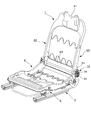
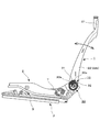
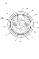
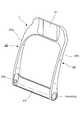
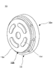
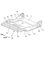
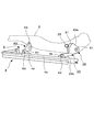
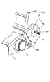
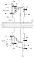
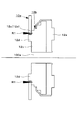
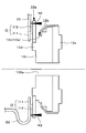
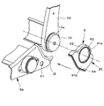
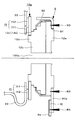
- FIG. 1 is a schematic perspective view of a vehicle seat according to an embodiment of the present invention. It is a schematic perspective view which shows the frame of the vehicle seat which concerns on one Embodiment of this invention. It is a schematic side view which shows the frame of the vehicle seat which concerns on one Embodiment of this invention. It is the schematic which shows the internal structure of the reclining mechanism which concerns on one Embodiment of this invention. FIG. 3 is an enlarged view around a reclining mechanism in FIG. 2. It is a schematic perspective view which shows the example of the shape of the seat back frame which concerns on one Embodiment of this invention. It is a schematic perspective view which shows the reclining mechanism which concerns on one Embodiment of this invention.
- FIG. 1 is a schematic perspective view of a seat cushion frame according to an embodiment of the present invention. It is explanatory drawing which shows the height adjustment mechanism which concerns on one Embodiment of this invention, and shows a state when a vehicle seat exists in a normal position. It is explanatory drawing which shows the height adjustment mechanism which concerns on one Embodiment of this invention, and shows a state when a vehicle seat exists in a raise position. It is a periphery expansion explanatory drawing of the reclining mechanism which concerns on one Embodiment of this invention.
- FIG. 12 is a cross-sectional explanatory view taken along line AA in FIG. 11. It is a description perspective view which shows the assembly
- FIG. 14 is an explanatory sectional view of a portion corresponding to the line AA, showing the assembled state of FIG. 13. It is a description perspective view which shows the assembly
- FIG. 16 is a cross-sectional explanatory view of a portion corresponding to the line AA showing the assembled state of FIG. 15. It is an explanatory schematic diagram showing a dissimilar material welding joining technique. It is a description perspective view which shows the assembly
- FIG. 19 is a cross-sectional explanatory view of a portion corresponding to the line AA showing the assembled state of FIG.
- FIG. 21 is a sectional view taken along line BB in FIG. 20. It is explanatory drawing which shows a 1st modification. It is CC sectional view explanatory drawing of FIG. It is explanatory drawing which shows the 2nd modification. It is explanatory drawing which shows the 3rd modification. It is explanatory drawing which shows the 4th modification. It is explanatory drawing which shows the 5th modification.
- the front-rear direction is a direction that coincides with the traveling direction of the vehicle
- the width direction is a direction along the lateral width of the vehicle, which is the width direction of the vehicle seat of the present invention.
- the vertical direction is the vertical direction of the vehicle.
- FIGS. 22 to 26 show a first modification example to a fifth modification example. With reference to these drawings, each modification example will be described after the description of the embodiment.
- the vehicle seat S includes a seat back S ⁇ b> 1, a seat cushion S ⁇ b> 2, and a headrest S ⁇ b> 3, and the seat back S ⁇ b> 1 and the seat cushion S ⁇ b> 2 are respectively attached to the frames 1 and 2.
- the cushion pads 1a and 2a are arranged and covered with the skin materials 1b and 2b.
- the headrest S3 has a configuration in which a cushion pad 3a is disposed on a core material (not shown) and is covered with a skin material 3b, and is supported by a headrest pillar HP attached to the seat back frame 1.
- the frame of the vehicle seat S includes a seat back frame 1 constituting the seat back S ⁇ b> 1 and a seat cushion frame 2 constituting the seat cushion S ⁇ b> 2 as main components.
- the seat cushion frame 2 has a substantially square shape in plan view, and a slide rail mechanism 4 for sliding the vehicle seat S in the front-rear direction and a height for moving the vehicle seat S in the vertical direction. It is attached to the vehicle body floor via a height adjusting mechanism 5.
- the seat back frame 1 has a substantially square shape in plan view, and in this embodiment is integrally formed of carbon fiber reinforced plastic (CFRP) as a resin material.
- CFRP carbon fiber reinforced plastic
- the seat back frame 1 is supported by connecting a lower end portion thereof to a rear end portion of the seat cushion frame 2 via a reclining mechanism 10 and a connecting bracket 9 attached thereto. In this state, the seat back frame 1 can rotate relative to the seat cushion frame 2 in the direction indicated by the arrow in FIG.
- the periphery of the connecting portion between the seat cushion frame 2 and the seat back frame 1 is the main configuration of the present invention, including the configurations of the reclining mechanism 10 and the connecting bracket 9, and will be described in detail later.
- the reclining mechanism 10 is attached to a predetermined position of the seat back frame 1 in order to support the seat back frame 1 in a rotatable state.
- the reclining mechanism 10 includes a reclining mechanism main body 11 that is driven when the seat back frame 1 is rotated, and a case 12 that accommodates the reclining mechanism main body 11 as main components.
- the reclining mechanism main body 11 the well-known thing is employ
- the sliding lock member 15 is provided, By the movement operation of the sliding lock member 15, the lock gear portion 14 attached to the sliding lock member 15 is engaged with or disengaged from the engagement gear 13.
- the state of the seat back frame 1 is changed between a locked state in which the seat back frame 1 is fixed to the seat cushion frame 2 and an unlocked state in which the seat cushion frame 2 can be rotated relative to the seat cushion frame 2. It is possible to switch.
- the case 12 that houses the reclining mechanism body 11 has a substantially cylindrical outer shape.
- the outer case piece 12a and the inner case piece 12b shown in FIG. It is configured in combination.
- Both the outer case piece 12a and the inner case piece 12b are made of metal, and the outer case piece 12a is joined to the seat cushion frame 2 side, and the engagement gear 13 is formed on the inner peripheral surface thereof.
- the above-mentioned sliding lock member 15 is provided inside thereof.
- the inner case piece 12b is joined to the seat back frame 1 side, and a pair of path defining portions 16 and 16 that define a moving path of the sliding lock member 15 sandwich the sliding lock member 15 inside thereof. Arranged in a state.
- a cam surface 17 is formed on the sliding lock member 15, and the cam body 18 that contacts the cam surface 17 is fixed to the rotating shaft 20 that penetrates the inner case piece 12 b and enters the case. Installed in condition.
- the sliding lock member 15 is disposed at a position where the lock gear portion 14 and the engagement gear 13 are engaged with each other in a normal state, and the state of the seat back frame 1 is It is locked.
- the operation lever T see FIG. 3
- the rotation shaft 20 is rotated by the operation, and the cam body 18 is rotated in conjunction with this, and the rotation state of the rotation state is increased.
- the cam body 18 abuts against the cam surface 17, the sliding lock member 15 moves between the path defining portions 16 and 16 in a direction away from the engagement gear 13.
- the lock gear portion 14 is disengaged from the engagement gear 13, and the state of the seat back frame 1 is unlocked.
- a connecting bracket 9 is welded or bonded to the reclining mechanism 10 and is connected to the seat cushion frame 2 via the connecting bracket 9, which will be described in detail later.
- a spiral spring P as an elastic member is applied to the lower end portion of the seat back frame 1 joined to the reclining mechanism 10 and the rear end portion of the seat cushion frame 2 as shown in FIG.
- the spiral spring P urges the seat back frame 1 to rotate forward when the seat back frame 1 is unlocked and the seat back S1 is tilted backward.
- the one end P1 is locked to a locking portion K1 provided on the seat back frame 1 side.
- the locking portion K1 is constituted by, for example, a sheet metal member fixed to the side frame 22 of the seat back frame 1, and one end portion P1 of the spiral spring P at a portion bent so as to extend outward in the width direction. Is hooked and locked.
- the other end portion P2 of the spiral spring P is locked to a locking portion K2 provided on the seat cushion frame 2 side, and the locking portion K2 also has a portion extending outward in the width direction. And the other end part P2 of the spiral spring P is latched by hooking the other end part P2 of the spiral spring P to the said part.
- the seat back frame 1 is made of CFRP, and in the present embodiment, is integrally molded by molding.
- the present invention is not limited to this, and it may be molded by a resin material other than CFRP, or a molding method other than mold molding, for example, a sheet made of a resin material is matched to a frame shape.
- the seat back frame 1 may be configured by laminating.
- the outer shape of the seat-back frame 1 is a substantially square shape in front view. More specifically, the seat back frame 1 includes an upper frame 21 extending along the width direction, a pair of side frames 22, 22 extending downward from both ends of the upper frame 21 in the width direction, and the side frame 22. The lower frame 23 which connected the lower end parts of each.
- the upper frame 21 is formed to be somewhat wider in the vertical direction.
- the cross section having the normal direction as the width direction has a closed cross section structure, that is, the cross sectional shape is a hollow rectangular shape. It has become.
- Each of the pair of side frames 22 and 22 is asymptotically wider from the upper side to the lower side, and its lower end is semicircular when viewed from the width direction. Further, each side frame 22 has a closed cross-sectional structure in which the vertical direction is a normal direction up to a midway position in the vertical direction. On the other hand, about the lower end part of each side frame 22, the cross-sectional shape is not a closed cross-sectional shape, and the width direction inner side part is formed in opening shape. This occurs because the seat back frame 1 as a molded product is removed from the mold in the mold forming process.
- each side frame 22 is not limited to the shape described above, and may have a closed cross-sectional structure up to the lower end.
- the cross-sectional structure from the upper end to the lower end of each side frame 22 may not be a closed cross-sectional structure.
- a reclining mechanism arrangement hole 22a is formed at the lower end portion of each side frame 22, and an annular mounting bracket 10a is attached to the portion, and the reclining mechanism 10 is arranged via the mounting bracket 10a.
- the rotating shaft 20 is configured to protrude from a shaft hole formed in the reclining mechanism 10.
- the rotating shaft 20 is disposed between the side frames 22 and 22 with the axial direction along the width direction, and the end of the rotating shaft 20 extends in the width direction from the outer surface 22b of the side frame 22 through the shaft hole. Projects outward. Then, the operation lever T is attached to a position outside the reclining mechanism 10.
- the number of the reclining mechanisms 10 may be two to be arranged on both sides in the width direction of the vehicle seat S, or 1 to be arranged only on one side in the width direction of the vehicle seat S. It is good also as only being provided.
- the lower frame 23 is provided so as to go around from the rear end of the lower end of each side frame 22 to the front surface, and has a substantially J-shape when viewed from the side.
- the reclining mechanism 10 is attached to the side frame 22. That is, the reclining mechanism 10 is attached to the outer side surface 22b facing the outer side in the width direction among the side surfaces of the side frame 22, more specifically, the lower end portion where the reclining mechanism arrangement hole 22a is formed.
- the entire seat back frame 1 including the side frames 22 is molded by CFRP as a resin material.
- the present invention is not limited to this, and at least the reclining mechanism 10 of the seat back frame 1 is used. As long as the portion to be attached is made of a resin material.
- the seat back frame 1 is integrally formed by molding, but the present invention is not limited to this, and the front portion (front shell) and the rear portion of the seat back frame 1 ( The seat back frame 1 may be formed by individually molding the rear shell) and then combining the two shells.
- the seat cushion frame 2 described above will be described in more detail.
- a pair of side frames 6a and 6b located at both ends in the width direction of the seat cushion frame 2 and rear ends of the side frames 6a and 6b.
- the rear end side connection part 7 which connects parts and the front end side connection part 8 which connects the front end parts of the side part frames 6a and 6b are provided.
- each part of the seat cushion frame 2 is integrally molded by CFRP as described above.
- the entire seat cushion frame 2 including the side frames 6a and 6b is molded by CFRP as a resin material.
- the side frames 6a and 6b may be made of a resin material, or at least the portion of the side frames 6a and 6b to which the connection bracket 9 is attached may be made of a resin material.
- the seat cushion frame 2 according to the present embodiment is manufactured by molding, but is not limited to this, and a molding method other than molding, for example, a sheet made of a resin material is framed. It is good also as shape
- the material of the seat cushion frame 2 is not limited to CFRP, and other resin materials may be used.
- the entire seat cushion frame 2 is molded by CFRP as a resin material, but an iron plate piece I2 is insert-molded at the rear ends of the side frames 6a and 6b. That is, in this embodiment, the iron plate piece I2 is insert-molded in the CFRP at the connection portion with the connection bracket 9.
- Each of the pair of side frames 6a, 6b is elongated along the front-rear direction of the vehicle seat S.
- the seat back frame 1, more specifically, is provided inside the rear end portions of the side frames 6a, 6b.
- the side frame 22 of the seat back frame 1 is attached via the reclining mechanism 10.
- the rear side link 30 mentioned later is assembled
- the “height adjusting mechanism mounting portion formed as a hole portion in which the link center axis is disposed” refers to, for example, the link assembly hole 51.
- the side frame 6a positioned on one end side in the width direction of the seat cushion frame 2 is referred to as one end side frame 6a and is opposed to the one end side frame 6a.
- the side frame 6b located on the other end side in the width direction of the seat cushion frame 2 is referred to as the other end side frame.
- the rear end side connecting portion 7 is formed to be somewhat wider along the front-rear direction.
- the seat back frame 1 is provided at the rear end portion of each of the one end side frame 6a and the other end side frame 6b. Is provided in front of the portion to which is attached.
- the rear end portion of the rear end side connecting portion 7 extends toward the seat back frame 1 in a state assembled to the rear end portions of the one end side frame 6a and the other end side frame 6b. I'm out.
- the part to which the seat back frame 1 is attached is located at the uppermost position in the rear end portions of the one end side frame 6a and the other end side frame 6b.
- the rear end side connecting portion 7 is provided at a position lower than a portion where the seat back frame 1 is attached.
- the rear end side connecting portion 7 has a rear end position above the front end position. That is, the rear end side connection part 7 is formed in a state inclined with respect to the front-rear direction, and the rear end part is assembled to each rear end part of the one end side frame 6a and the other end side frame 6b. It extends toward the seat back frame 1 in a state.
- the front surface is a surface that supports the waist of the occupant seated on the vehicle seat S, so that the central portion swells rearward.
- the curved surface is curved.
- the front end side connecting portion 8 is a portion corresponding to a so-called pan frame, and is developed rearward from the front end of each of the one end side frame 6a and the other end side frame 6b.
- recesses 8 a, 8 b, and 8 c are formed at a plurality of locations on the front end side connecting portion 8 for the purpose of improving rigidity.
- Each recessed part 8a, 8b, 8c is formed when the site
- the concave portion 8c located most rearward among the concave portions 8a, 8b, 8c is a substantially square-shaped depression in plan view formed at the center in the width direction of the rear end portion of the front end side connecting portion 8.
- an opening 2 ⁇ / b> X having a rectangular shape in plan view is formed between the rear end side connecting portion 7 and the front end side connecting portion 8, and an S spring or the like laid above the opening 2 ⁇ / b> X.
- the support member supports the occupant's buttocks seated on the vehicle seat S.
- a portion of the front end side connecting portion 8 that is positioned between the recess 8c formed in a substantially square shape in plan view and the one end side frame 6a or the other end side frame 6b is seated on the vehicle seat S. It functions as a leg support part 8d that supports the leg part of the occupant.
- the leg support portion 8d is positioned between the concave portion 8c having a substantially square shape in plan view and the one end side frame 6a or the other end side frame 6b in the front end side connecting portion 8, so that the rigidity is high. Since it is provided in the part which became, it can support a passenger
- the entire seat cushion frame 2 including the one end side frame 6a and the other end side frame 6b is molded by CFRP as a resin material.
- the present invention is not limited to this, and the seat cushion frame 2 is not limited thereto.
- at least a portion where the rear side link 30 and the front side link 40 are assembled may be made of a resin material.
- the height adjustment mechanism 5 is disposed between the seat cushion frame 2 and the slide rail mechanism 4 in the vertical direction, and operates by operating an operation unit (not shown).
- the height adjustment mechanism 5 includes a rear side link 30 as an example of a rotating body and a front side link 40 as main components.
- the rear side link 30 is attached to the rear end of each of the one end side frame 6a and the other end side frame 6b, and rotates with respect to the link support protrusion 4b provided on the movable rail 4a of the slide rail mechanism 4. It is supported freely.
- the rear side link 30 includes a first rotating arm 33 in which a sector gear 31 is formed. When a driving force is transmitted to the sector gear 31 from the pinion gear 25 interlocked with the operation unit, the driving force is used. It rotates so as to move between the position shown in FIG. 9 and the position shown in FIG.
- the first rotation arm 33 is pivotally supported by the link support protrusion 4b of the movable rail 4a (supported by the second shaft pin 62) and is disposed in the link assembly hole 51.
- the first shaft pin 61 is rotatably supported with respect to the one end side frame 6a.
- the 1st rotation arm 33 is connected with the 2nd rotation arm 34 (not shown) via the connection pipe 35 which is not shown in figure, Therefore, the 2nd rotation arm 34 is 1st rotation. It rotates integrally with the arm 33.
- the second turning arm 34 (not shown) is arranged at a position facing the first turning arm 33 in the width direction in a state where the height adjusting mechanism 5 is attached to the seat cushion frame 2.
- the second rotating arm 34 (not shown) is rotatably assembled to the other end side frame 6 b at one end thereof.
- the 2nd rotation arm 34 is assembled
- a front side link member 41 constituting the front side link 40 is attached to the front end of each of the one end side frame 6a and the other end side frame 6b. Since the front side link 40 has a left-right symmetric structure, only the structure on one end side in the left-right direction, that is, the width direction will be described below.
- One end of the front side link member 41 is rotatably supported (supported by a sixth shaft pin 66) with respect to a link support protrusion 4d provided on the movable rail 4a of the slide rail mechanism 4. Yes, the other end side is attached to the one end side frame 6a so as to be rotatable (supported by the fifth shaft pin 65). For this reason, this front side link member 41 is interlocked when the rear side link 30 is rotated, and is rotated so as to move between the position shown in FIG. 9 and the position shown in FIG.
- a similar link structure is also formed on the other end side frame 6b, and a pair of front side link members 41 is formed. Since the pair of front side link members 41 are connected by a connection pipe 42 (not shown), both of them turn together when turning.
- the vertical position of the vehicle seat S is moved from the normal position shown in FIG. 9 to the raised position shown in FIG. It is possible to return to
- a driving force is transmitted from an operation unit (not shown) to a pinion gear 25 provided in the rear side link 30, and the pinion gear 25 is provided with a brake mechanism.
- a known mechanism is employed as the brake mechanism, and a so-called “brake pinion” is used.
- the pinion gear 25 is attached to a drive shaft of a brake member that controls the rotation of the pinion gear 25.
- the brake member holds the operation unit (not shown) in a neutral state and brakes the drive shaft to suppress rotation.
- the brake member amplifies the rotational force and applies torque so as to give a large rotational output to the drive shaft with a light force. And rotate the pinion gear.
- the brake mechanism is disposed so that the drive shaft projects from the brake member disposing hole 55 toward the inside of the one end side frame 6a in a state where the brake member protrudes to the outside of the one end side frame 6a. Is done. And the pinion gear 25 is attached to the edge part (side arrange
- the brake member disposing hole 55 is a through hole formed in the one end side frame 6a, and is formed slightly on the vehicle front side from the link assembling hole 51.
- the “link drive member” in the claims refers to, for example, this brake mechanism (pinion gear 25, drive shaft, brake member), and “a height adjustment mechanism formed as a hole in which the link drive member is disposed.
- the “attachment portion” refers to the brake member disposing hole 55.
- the attachment structure of the reclining mechanism 10 to the outer side surface 22b of the side frame 22 will be described.
- the case 12 of the reclining mechanism 10 more specifically, the outer surface 12 c of the inner case piece 12 b is bonded and fixed to the outer surface 22 b of the side frame 22.
- the material of the inner case piece 12b is metal
- the material of the side frame 22 is CFRP. Therefore, when the case 12 of the reclining mechanism 10 is joined and fixed to the outer surface 22b of the side frame 22, welding is performed. It is difficult to fix with.
- the case 12 of the reclining mechanism 10 is attached to a portion of the outer surface 22b of the side frame 22 where the reclining mechanism 10 is attached, A method for connecting the frames 6a and 6b and the structure of the side frames 6a and 6b will be described.
- connection bracket 9 is also used on the side frame 6b (other end frame 6b) side.
- the present invention is not limited to this, and the side frame 6b (other end frame 6b) is not limited thereto.
- the structure which does not use the connection bracket 9 on the () side may be sufficient.
- FIGS. 11 to 21 simplify the illustration of the reclining mechanism 10 and the like for the sake of explanation (the details of the internal structure and the like are as described above).
- a connecting bracket 9 is connected to the rear end of the side frame 6a, and the side frame 22 is connected to the side frame 6a via the connecting bracket 9 and the reclining mechanism 10. Is installed.
- the connecting bracket 9 is laser welded to the side frame 6a. However, it is not restricted to this, You may attach with the adhesive agent.
- the reclining mechanism 10 is also laser-welded to the side frame 22. Similarly to the above, it may be attached by an adhesive. Thus, in this embodiment, since the reclining mechanism 10 is attached to the outer side surface 22b of the side frame 22 by laser welding or an adhesive, for example, the reclining mechanism 10 is overmolded into the frame when the seat back frame 1 is formed. Thus, the structure for attaching the reclining mechanism 10 to the side frame 22 is not complicated, and the reclining mechanism 10 can be attached more easily.
- the reclining mechanism 10 is attached to an annular mounting bracket 10a.
- region 12e (outer peripheral part) in which the positioning protrusion 12d is not formed in the outer surface 12c of the inner side case piece 12b is laser-welded to the periphery of the attachment hole 100a of the attachment bracket 10a. This welding point is indicated by R1.
- the mounting bracket 10 a to which the reclining mechanism 10 is attached is laser welded to the outer peripheral portion of the reclining mechanism arrangement hole 22 a formed in the side frame 22.
- annular iron plate piece I1 is attached to the reclining mechanism arrangement hole 22a.
- This iron plate piece I1 has an inner peripheral iron plate piece I11 and an outer peripheral iron plate piece I12.
- the inner peripheral iron plate piece I11 is an annular iron plate, and is configured such that the outer peripheral diameter thereof is substantially the same as the reclining mechanism arrangement hole 22a.
- the outer peripheral iron plate piece I12 is an annular member, and is configured such that the inner peripheral diameter thereof is substantially the same as the reclining mechanism arrangement hole 22a.
- the outer peripheral iron plate piece I12 is laminated on a concentric circle so that the inner peripheral diameter portion thereof is aligned with the outer peripheral portion of the inner peripheral iron plate piece I11.
- the cross-sectional shape becomes a shape in which a step corresponding to the thickness of the inner peripheral iron plate piece I11 is formed.
- step-difference part and the thickness of the side frame 22 lower end part are comprised so that it may become substantially the same. That is, the iron plate piece I1 is insert-molded in such a manner that the outer peripheral iron plate piece I12 extends to the outer surface of the side frame 22 while being engaged with the reclining mechanism arrangement hole 22a by the step portion.
- the attachment bracket 10a to which the reclining mechanism 10 was attached is welded to the outer surface of this outer periphery iron plate piece I12. This welding point is indicated by R2.
- the iron plate piece I1 was insert-molded at the welded portion of CFRP, which is a resin, and the outer peripheral iron plate piece I12 was exposed as a welding surface. And both are joined by welding the attachment bracket 10a which is a metal to this part. Since it comprised in this way, while being able to connect the resin raw material and metal raw material which are different materials by welding, since the iron plate piece I1 is insert-molded, the rigidity of the said part also improves.
- a metallic connecting bracket 9 is laser welded to the reclining mechanism 10 attached to the side frame 22 and the rear end portion of the side frame 6a.
- the connecting bracket 9 corresponds to a “connecting member”.
- the connecting bracket 9 is configured to include a bottom surface portion 91 and an outer peripheral edge portion 92.
- the bottom surface portion 91 is partially curved in an arc shape so as to be along a part of the outer periphery of the reclining mechanism 10, and extends from this portion so as to follow the shape of the rear end portion of the side frame 6 a.
- the formed part is formed.
- the outer peripheral edge part that bends and extends substantially perpendicularly to the bottom face part 91 along the arcuate part and the part extending from this part so as to follow the shape of the rear end side of the side frame 6a. 92 is formed.
- the outer peripheral edge 92 extends from the upper part of the reclining mechanism 10 along the upper edge of the rear end of the side frame 6a and covers the part. Further, the height of the outer peripheral edge portion 92 (distance from the bottom surface portion 91) is configured to be substantially the same as the thickness of the reclining mechanism 10, so that a space in which the reclining mechanism 10 is present can be secured. It becomes possible. Further, a circular hole portion 91a is formed in the bottom surface portion 91 so that the outer surface of the outer case piece 12a is exposed.
- a portion that constitutes the connecting bracket 9 and extends along the shape of the rear end portion of the side frame 6a is referred to as a “side frame attached portion 91b”.
- the connecting bracket 9 is provided so as to align the position where the hole portion 91a is formed and the arc portion on the upper portion thereof with the reclining mechanism 10 welded to the side frame 22, and the side frame attached portion 91b. Is aligned with the rear end of the side frame 6a. In this state, the peripheral portion of the hole 91a and the outer case piece 12a are welded (this welding point is denoted as R3), and the side frame attached portion 91b and the rear end portion of the side frame 6a are welded. (This weld point is denoted as R4).
- the side frame attached portion 91b When the side frame attached portion 91b is attached to the rear end portion of the side frame 6a, the side frame attached portion 91b is curved so as to escape to the rear side with respect to the link assembly hole 51 (so as to protrude toward the upper front portion). ). For this reason, when the height adjusting mechanism 5 is assembled, it is possible to effectively prevent the connecting bracket 9 from hindering the assembling work.
- connection bracket 9 is configured such that the lower side (the side welded to the side frame 6a) has a larger area than the upper part. Thereby, it becomes possible to make the welding range with respect to the side part frame 6a large, and attachment rigidity improves more.
- an iron plate piece I is insert-molded in the rear end portion of the side frame 6a.
- the iron plate piece I2 is insert-molded along the shape of the rear end portion of the side frame 6a. That is, in the present embodiment, the iron plate piece I2 is bent from the outer surface of the rear end portion of the side frame 6a to the edge portion ("upper side surface") that extends inward from the upper portion of the outer surface. Equivalent). For this reason, the covering bracket 9 is welded and joined in a state where the iron plate piece I2 disposed over the outer side surface and the upper side surface of the rear end portion of the seat cushion frame is covered.
- the iron plate piece I2 is integrated over the outer side surface and the upper side surface, but is insert-molded on a part of the outer side surface and a part of the upper side surface (that is, a plurality of components). As an insert molding).
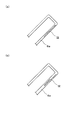
- FIG. 21 (a) a flat steel plate is inserted as an iron plate piece I2.
- the present invention is not limited to this, and as shown in FIG. 21 (b), the cross section It is good also as a structure with a level
- the welding joint between the side frame 6a formed of CFRP and the connection bracket 9 which is a metal member will be briefly described.
- the iron plate piece I was used in order to join CFRP which is resin and a metal by welding. That is, the iron plate piece I2 was insert-molded at the welded portion of CFRP, which is a resin, to expose the weld surface. Then, by welding the side frame attached portion 91b of the connecting bracket 9 which is a metal to this portion, both are joined.
- the lower end portion of the side frame 22 and the rear end portion of the side frame 6a are connected by the four welding points R1, R2, R3, R4 via the connecting bracket 9 and the reclining mechanism 10. And are connected so as to be rotatable. Since it is configured in this way, it is possible to easily assemble, and since parts such as fastening members are not necessary, the number of parts can be reduced, the enlargement of the reclining mechanism 10 can be suppressed, and cost can be reduced. Is also advantageous.
- the side frame attached portion 91b extends to a position where it wraps in the vertical direction with the rear end portion of the link assembly hole 51. Due to such a configuration, the rigidity in the vicinity of the link assembling hole 51 is improved, and accordingly, the rigidity of the height adjusting mechanism 5 is improved.
- the iron plate piece I2 inserted at a position aligned with the side frame attached portion 91b also extends to a position where it overlaps with the rear end portion of the link assembly hole 51 in the vertical direction. Therefore, the rigidity in the vicinity of the link assembling hole 51 is further improved, and accordingly, the rigidity of the height adjusting mechanism 5 is further improved.
- the outer surface 12c of the inner case piece 12b is not limited to the case in which the positioning projection 12d is formed, and the front surface may be flat without the positioning projection 12d being formed on the outer surface 12c.
- the positioning area 12d since the positioning area 12d is not provided, the welding area can be increased. Therefore, the reclining mechanism 10 can be more favorably connected to the side frame 22, and the mounting position can be stably maintained. It becomes possible to arrange.
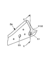
- the first modified example is an example in which the insert range of the second iron plate piece I102 is different. Other configurations are the same as those in the above embodiment, and thus the description thereof is omitted.
- the insert range of the second iron plate piece I102 extends to the peripheral edge of the link assembling hole 51. That is, the second iron plate piece I102 is disposed (insert molded) so as to surround the periphery of the link assembly hole 51. With this configuration, the rigidity in the vicinity of the link assembly hole 51 is improved, and the rigidity of the height adjusting mechanism 5 is improved.
- FIG. 23 is a cross-sectional view taken along the line CC of FIG. FIG. 23A shows a state where the iron plate piece I102 is not insert-molded.
- insert molding is performed so that the iron plate piece I102 is disposed around the link assembly hole 51.
- the present invention is not limited thereto, and insert molding may be performed so that the iron plate piece I102 goes around to the inner wall portion of the link assembling hole 51 as shown in FIG.
- the link assembling hole 51 is a hole on which the rear side link 30 (sector gear 31) of the height adjusting mechanism 5 is pivotally supported. Therefore, it is preferable that further rigidity can be secured.
- the second modified example is an example in which the insert range of the third iron plate piece I202 is different.
- Other configurations are the same as those in the above embodiment, and thus the description thereof is omitted.
- the insert range of the third iron plate piece I202 extends to the peripheral edge of the brake member disposing hole 55.
- the rigidity in the vicinity of the brake member disposition hole 55 is improved, and the rigidity of the height adjusting mechanism 5 is improved.
- the brake member disposing hole 55 is a hole on which the pinion gear 25 with the brake member is pivotally supported, it is preferable that further rigidity can be ensured.
- the configuration around the brake member disposition hole 55 and the inner wall surface is the same as in FIG.
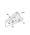
- the third modified example is an example in which the insert range of the fourth iron plate piece I302 is different.
- Other configurations are the same as those in the above embodiment, and thus the description thereof is omitted.
- the insert range of the fourth plate piece I202 extends to the peripheral edge portions of the link assembling hole 51 and the brake member disposing hole 55.
- the link assembling hole 51 is a hole on which the rear side link 30 (sector gear 31) of the height adjusting mechanism 5 is pivotally supported. Therefore, it is preferable that further rigidity can be secured.
- the brake member disposing hole 55 is a hole on which the pinion gear 25 with the brake member is pivotally supported, it is preferable that further rigidity can be secured.
- the configurations of the link assembly hole 51 and the brake member disposition hole 55 and the inner wall surface are the same as those in FIG.
- FIG. 6a A fourth modification will be described with reference to FIG.
- the rear end portion of the side frame 6a is modified.
- An iron plate piece I is insert-molded at the rear end portion of the side frame 6a as shown in FIGS.
- the fifth iron plate piece I402 is insert-molded along the shape of the rear end portion of the side frame 6a, but its cross-sectional shape is modified as shown in FIG. That is, it has a shape in which a cross-sectional convex portion I402a protruding toward the connecting bracket 9 is formed, and this cross-sectional convex portion 1402a portion is insert-molded in the side frame 6a.
- the top surface portion I402b of the cross-sectional convex portion I402a is exposed to the connecting bracket 9 side, and the connecting bracket 9 covers the top surface portion I402b and the covering portion (welding point R5) is covered. It will be welded. For this reason, the attachment rigidity of the connection bracket 9 will be further improved. Further, with this configuration, the surface exposed to the surface can be used as a welding surface, and the side disposed on the inner side improves rigidity without affecting the appearance. Contribute to.
- FIG. 18 to FIG. 21 A fifth modification will be described with reference to FIG.
- the rear end portion of the side frame 6a is modified.
- the iron plate piece I is insert-molded in the rear end portion of the side frame 6a.
- the iron pin I502 instead of the iron plate piece I, the iron pin I502 is used.
- a frame side iron pin through hole H1 is appropriately formed at the rear end portion of the side frame 6a, and an iron pin I502 is fixed to the frame side iron pin through hole H1. That is, the iron pin I502 is fixed so that the head of the iron pin I502 is disposed on the inner side and the free end portion side of the leg projects outward (on the connection bracket 9 side).
- bracket side iron pin through-hole H2 is formed in the position which aligns with this iron pin through-hole H1 in the connection bracket 9, and the connection bracket 9 is a frame side iron pin through-hole H1 and a bracket side iron pin penetration.
- the rear end portion of the side frame 6a is provided so as to communicate with the hole H2, and the leg portion of the iron pin I502 is inserted into the bracket side through hole H2.
- the contact portion (welding point R6) between the bracket side through hole H2 and the iron pin I502 is welded.
- the attachment rigidity of the connection bracket 9 will be further improved.
- the frame side iron pin through-hole H1 and bracket side through-hole H2 vicinity are reinforced by the head of the iron pin I502 arrange
Landscapes
- Engineering & Computer Science (AREA)
- Aviation & Aerospace Engineering (AREA)
- Transportation (AREA)
- Mechanical Engineering (AREA)
- Seats For Vehicles (AREA)
- Chair Legs, Seat Parts, And Backrests (AREA)
Description
このような車両用シートの一例としては、シートバックフレームを含むシートバックをシートクッションに対して相対回動可能な状態で支持するリクライニング機構が備えられており、このリクライニング機構と連結される、例えばシートクッションフレームが樹脂材料によって成形されているものが知られている。
このような構成例としては、例えば、シートクッションフレーム全体が、熱可塑性マトリクス及び補強用ファイバを有してなる複合材料によって一体部材として成形されているもの等が提案されている。
この車両用シートを構成するフレームサイドには、ボルト孔が形成されており、このボルト孔で、リクライニング・デバイスのヒンジブラケットをボルト締めすることにより組付ける。
このようにして、リクライニング・デバイスは、(ヒンジブラケットを)ボルト締めすることにより、クッションフレームに取付けられる。
したがって、車両用シートを製造する上で、リクライニング機構をシートクッションフレーム中、樹脂材料により成形された樹脂成形部に対してより容易に取付け、他部品取付工程において、作業性を向上させることが強く望まれていた。
また、これに伴い、部品点数を減らし、コスト面においても有利な技術が望まれていた。
また、本発明の他の目的は、リクライニング機構とシートクッションフレームとの連結を容易にしながらも、リクライニング機構及びシートクッションフレーム周りの取付け剛性が確保された車両用シートを提供することにある。
また、本発明の他の目的は、リクライニング機構を取付けるための部品を別途用いながらも、部品点数の増加が抑えられた車両用シートを提供することにある。
つまり、本発明では、金属性の連結部材と、シートクッションフレームの後端側に一体形成された金属部材とを溶接接合することができるよう構成した。
このため、例えば、ボルト締めによる固定を行うことが不要となり、作業工程を少なくすることが可能となる。そして、これに伴い、取付け作業性が向上する。
また、連結部材を使用して溶接接合を行うため、連結部材以外の締結部材(例えば、ボルト等)を使用する必要がなく結果的に部品点数を少なくすることができる。
なお、リクライニング機構もまた、溶接によりシートバックフレームに接合することとすれば、シートバックフレームの樹脂成形部を成形する際にリクライニング機構をオーバーモールドする場合とは異なって、リクライニング機構を樹脂成形部に取付ける構造が複雑なものとならず、リクライニング機構の取付けを容易に行うことが可能となり、更に、作業性が向上する。
このように構成されていると、連結部材と金属部材とが、シートクッションフレームの外側面と上側面とにおいて、これらが積層された部分にて連結が行われることとなるため、連結部材の取付け剛性が向上する。
このように構成されていると、高さ調整機構取付部付近の剛性が向上する。
このように構成されていると、孔部の剛性が向上し、リンクの取付け剛性やリンク駆動部材(例えば、ブレーキ機構等)の取付け剛性が向上する。
このように構成されていると、直線上に溶接箇所が形成されている場合に比して、溶接面積を大きく確保することができるため、連結部材の取付け剛性が向上する。
このように構成されていると、高さ調整機構取付部付近の剛性が向上する。
このように構成されていると、連結部材において、溶接部分とリクライニング機構との間の距離を確保することができるため、連結部材の剛性が向上する。
また、連結部材の取付け剛性も同様に向上する。
このように構成されていると、溶接面積を大きく確保することが可能となり、取付け剛性が向上する。
このように構成されていると、(溶接)取付剛性が向上するとともに、溶接部周辺の剛性もまた向上する。
このように構成されていると、(溶接)取付剛性が向上するとともに、溶接部周辺の剛性もまた向上し、これに加え、シートクッションフレームと連結部材との接合が容易になる。
このように構成されていると、連結部材と金属部材とが、シートクッションフレームの外側面と上側面とにおいて、これらが積層された部分にて連結が行われることとなるため、連結部材の取付け剛性が向上するとともに、シートクッションフレーム外側面の後方から前方に向けてのラインが補強されるため剛性が向上する。
そして、この後方から前方に延在する部分に、部品等の取付部(例えば、取付孔等)を形成した場合に、当該部分が強化されて剛性が向上する。
つまり、シートバックフレームに取付られたリクライニング機構とシートクッションフレームとの連結を容易に行うことが可能である。
また、連結部材を使用して溶接接合を行うため、連結部材以外の締結部材(例えば、ボルト等)を使用する必要がなく結果的に部品点数を少なくすることができる。
請求項2の車両用シートによれば、シートクッションフレームの外側面と上側面とにおいて、これらが積層された部分にて連結が行われることとなるため、連結部材の取付け剛性が向上する。
請求項3の車両用シートによれば、高さ調整機構取付部付近の剛性が向上する。
請求項4の車両用シートによれば、リンクの取付け剛性やリンク駆動部材(例えば、ブレーキ機構等)の取付け剛性が向上する。
請求項5の車両用シートによれば、直線上に溶接箇所が形成されている場合に比して、溶接面積を大きく確保することができるため、連結部材の取付け剛性が向上する。
請求項6の車両用シートによれば、高さ調整機構取付部付近の剛性が向上する。
請求項7の車両用シートによれば、溶接部分とリクライニング機構との間の距離を確保することができるため、連結部材の剛性及び連結部材の取付け剛性が共に向上する。
請求項8の車両用シートによれば、溶接面積を大きく確保することが可能となり、取付け剛性が向上する。
請求項9の車両用シートによれば、高さ調整機構の組付け作業を阻害することを有効に防止できる。
請求項10の車両用シートによれば、高さ調整機構取付部(孔部周辺部)の剛性が向上する。
請求項11の車両用シートによれば、ブレーキピニオン機構の取付部周辺の剛性が向上する。
請求項12の車両用シートによれば、溶接による取付剛性が向上するとともに、溶接部周辺の剛性もまた向上する。
請求項13の車両用シートによれば、溶接による取付剛性が向上するとともに、溶接部周辺の剛性もまた向上し、これに加え、シートクッションフレームと連結部材との接合が容易になる。
請求項14の車両用シートによれば、連結部材の取付剛性が向上するとともに、シートクッションフレームの側面部分の剛性が向上する。
ヘッドレストS3は、不図示の心材にクッションパッド3aを配して表皮材3bで被覆された構成となっており、シートバックフレーム1に取付けられたヘッドレストピラーHPによって支持される。
シートクッションフレーム2は、平面視で略ロの字形状となっており、車両用シートSを前後方向にスライド移動させるためのスライドレール機構4及び車両用シートSを上下方向に移動させるための高さ調整機構5を介して車体フロアに取付けられている。
シートバックフレーム1は、その下端部がリクライニング機構10及びこれに取付けられる連結ブラケット9を介してシートクッションフレーム2の後端部に連結されることで支持される。
かかる状態においてシートバックフレーム1は、シートクッションフレーム2に対して図3中、矢印にて示す方向に相対回動することが可能となっている。
なお、シートクッションフレーム2とシートバックフレーム1との連結部分周辺に関しては、リクライニング機構10及び連結ブラケット9の構成を含め、本発明の主要構成であるため、後に詳述する。
このようなリクライニング機構本体11により、シートバックフレーム1の状態を、シートクッションフレーム2に対して固定されたロック状態と、シートクッションフレーム2に対して相対回動可能なアンロック状態との間で切り替えることが可能である。
外側ケース片12a及び内側ケース片12bは、いずれも金属製であり、外側ケース片12aについては、シートクッションフレーム2側に接合されており、その内周面には前述の係合ギア13が形成され、更にその内側には前述の摺動ロック部材15が設けられている。
また、摺動ロック部材15にはカム面17が形成されており、このカム面17に当接するカム体18については、内側ケース片12bを貫通してケース内に進入した回動軸20に固定状態に取付けられている。
かかる状態にあるときに、操作レバーT(図3参照)が操作されると、その操作により回動軸20が回転するようになり、これに連動してカム体18が回転し、回転状態のカム体18がカム面17に当接することにより、摺動ロック部材15が経路規定部16,16の間を係合ギア13から離れる向きに移動する。
この結果、ロックギア部14が係合ギア13から離脱し、シートバックフレーム1の状態がアンロック状態となる。
この結果、操作レバーTの操作が終了すると、再びロックギア部14が係合ギア13に係合し、シートバックフレーム1の状態がロック状態に復帰するようになる。
なお、リクライニング機構10には、連結ブラケット9が溶接若しくは接着されており、この連結ブラケット9を介して、シートクッションフレーム2と連結されているが、この構成に関しては、後に詳述する。
この渦巻きバネPは、シートバックフレーム1の状態がアンロック状態にあり、かつ、シートバックS1が後傾状態にあるときに、シートバックフレーム1を前方に回動させるように付勢するものであり、その一端部P1は、シートバックフレーム1側に設けられた係止部K1に係止されている。
ここで、係止部K1は、例えば、シートバックフレーム1のサイドフレーム22に固定された板金部材により構成され、幅方向外側に延出するように折れ曲った部分に渦巻きバネPの一端部P1が引っ掛けられて係止されるようになる。
シートバックフレーム1は、前述したように、CFRPからなり、本実施形態では金型成形によって一体的に成形される。ただし、これに限定されるものではなく、CFRP以外の樹脂材料によって成形されるものであってもよく、あるいは、金型成形以外の成形方法、例えば、樹脂材料からなるシートをフレーム形状に合わせて積層させることでシートバックフレーム1を構成することとしてもよい。
上部フレーム21は、上下方向に幾分幅広に形成されており、本実施形態では、幅方向を法線方向とする断面が閉断面構造となっており、すなわち、当該断面形状が中空矩形状となっている。
また、各サイドフレーム22は、上下方向の中途位置まで、上下方向を法線方向とする断面形状が閉断面構造となっている。
一方、各サイドフレーム22の下端部については、その断面形状が閉断面形状となっておらず、幅方向内側の部分が開口状に形成されている。
これは、金型成形処理において成形品であるシートバックフレーム1をモールドから抜くために生じるものである。
なお、回動軸20は、リクライニング機構10に形成される軸孔から突出するよう構成されている。そして、回動軸20は、軸方向が幅方向に沿った状態でサイドフレーム22,22間に配置され、回動軸20の端部は、軸孔を通じてサイドフレーム22の外側面22bから幅方向外側に突出するようになる。
そして、リクライニング機構10よりも外側の位置に操作レバーTが取付けられる。
つまり、リクライニング機構10は、サイドフレーム22の側面のうち、幅方向の外側に面した外側面22b、より具体的には、リクライニング機構配設孔22aが形成された下端部に取付けられる。
なお、本実施形態では、側部フレーム6a,6bを含むシートクッションフレーム2全体が樹脂材料としてのCFRPにより成形されているが、これに限定されるものではなく、シートクッションフレーム2のうち、少なくとも、側部フレーム6a,6bが樹脂材料からなるもの、若しくは、少なくとも側部フレーム6a,6bのうち、連結ブラケット9が取付けられる部分が一部樹脂材料からなるものであってもよい。
また、本実施形態に係るシートクッションフレーム2は金型成形によって製造されるものであるが、これに限定されるものではなく、金型成形以外の成形方法、例えば、樹脂材料からなるシートをフレーム形状に合わせて積層させることで成形することとしてもよい。また、シートクッションフレーム2の材質についても、CFRPに限定されるものではなく、他の樹脂材料であってもよい。
つまり、本実施形態では、連結ブラケット9との連結部分においては、CFRPに鉄板片I2がインサート成形されている。
この鉄板片I1のインサート範囲等の詳細は、本発明の主要構成であるため、後に詳述する。
具体的に説明すると、側部フレーム6a,6bの後端部には、それぞれ、リア側リンク30を組付けるために形成されたリンク組付用孔51,52が形成されている。
さらに、側部フレーム6a,6bの前端部には、後述するフロント側リンク40が組付けられる。具体的に説明すると、側部フレーム6a,6bの前端部には、それぞれ、フロント側リンク40を組付けるために形成されたリンク組付用孔53,54が形成されている。
なお、「リンク中心軸が配設される孔部として形成される高さ調整機構取付部」は、例えば、リンク組付用孔51を指す。
また、本実施形態では、後端側連結部7の後端部が、一端側フレーム6a及び他端側フレーム6bの各々の後端部に組付けられた状態のシートバックフレーム1に向かって延出している。
本実施形態においては、図8に示すように、剛性向上の目的から、前端側連結部8の複数箇所に凹部8a,8b,8cが形成されている。
各凹部8a,8b,8cは、前端側連結部8中、当該凹部8a,8b,8cが設けられる部位が下方に窪むことにより形成されている。
かかる凹部8a,8b,8cの中で最も後方に位置する凹部8cは、前端側連結部8の後端部の幅方向中央に形成された平面視略正方形状の窪みである。
また、前端側連結部8のうち、平面視略正方形状に窪んで形成された凹部8cと一端側フレーム6a、あるいは他端側フレーム6bとの間に位置する部分は、車両用シートSに着座した乗員の脚部を支える脚支え部8dとして機能する。
そして、本実施形態では脚支え部8dが、前端側連結部8中、平面視略正方形状の凹部8cと一端側フレーム6a、あるいは他端側フレーム6bとの間に位置することによって剛性が高くなった部分に設けられているため、乗員の脚部を安定して支えることが可能である。
本実施形態に係る高さ調整機構5は、上下方向においてシートクッションフレーム2とスライドレール機構4との間に配置され、不図示の操作部が操作されることにより動作する。
リア側リンク30は、一端側フレーム6a及び他端側フレーム6bの各々の後端部に対して取付けられるとともに、スライドレール機構4の可動レール4aに設けられたリンク支持突起4bに対して回動自在に支持されるものである。
このリア側リンク30は、セクターギア31が形成された第1回動アーム33を備え、上記の操作部に連動するピニオンギア25から駆動力がセクターギア31に伝達されると、当該駆動力により図9に示した位置と図10に示した位置との間を移動するように回動する。
また、第1回動アーム33は、図示しない連結パイプ35を介して第2回動アーム34(図示せず)と連結されており、このため、第2回動アーム34は、第1回動アーム33と一体的に回動する。
フロント側リンク40は、左右対称の構造となっているため、以下では左右方向、すなわち、幅方向の一端側の構造のみを説明する。
このため、このフロント側リンク部材41は、リア側リンク30が回動した際に連動し、図9に示した位置と図10に示した位置との間を移動するように回動する。
この一対のフロント側リンク部材41は、図示しない連結パイプ42によって連結されているため、回動する際には双方が一体的に回動することとなる。
ブレーキ機構は、公知の機構が採用されており、所謂「ブレーキピニオン」が使用されている。
ブレーキ部材は、操作部(図示せず)が操作されない状態(通常状態)においては、操作部(図示せず)をニュートラル状態に保持し、駆動軸にブレーキをかけて回転を抑制する。
一方、操作部(図示せず)が操作されてブレーキ部材に回転力が入力されると、ブレーキ部材は、この回転力を増幅させて軽い力で駆動軸に大きな回転出力を与えるようトルクを付与し、ピニオンギアを回転させる。
そして、この駆動軸の端部(一端側フレーム6aの内側に配設される側)にピニオンギア25が取付けられる。
なお、請求項の「リンク駆動部材」は、例えば、このブレーキ機構(ピニオンギア25、駆動軸、ブレーキ部材)を指し、「リンク駆動部材が配設される孔部として形成される高さ調整機構取付部」とは、ブレーキ部材配設孔55を指す。
リクライニング機構10をサイドフレーム22に取付ける際、リクライニング機構10のケース12、より具体的には、内側ケース片12bの外表面12cをサイドフレーム22の外側面22bに接合固定することになる。ここで、内側ケース片12bの材質が金属であるのに対し、サイドフレーム22の材質がCFRPであるので、リクライニング機構10のケース12をサイドフレーム22の外側面22bに接合固定する際に、溶接にて固定することが困難である。
次いで、図11乃至図21により、サイドフレーム22と、側部フレーム6a,6bとを連結する方法について説明する。
なお、主要構成は、両側共に同様であるため、サイドフレーム22と側部フレーム6a(一端側フレーム6a)とを、リクライニング機構10を介して連結する方法について説明する。
更に、図11乃至図21は、説明のためにリクライニング機構10等の図示を簡略化している(内部構造等の詳細については、上記の通りである)。
なお、本実施形態においては、連結ブラケット9は、側部フレーム6aにレーザ溶接されている。
しかし、これに限られることはなく、接着剤により取付けられていてもよい。
これも、上記同様、接着剤により取付けられていてもよい。
このように本実施形態では、レーザ溶接若しくは接着剤によって、リクライニング機構10をサイドフレーム22の外側面22bに取付けるので、例えばシートバックフレーム1の成形時にリクライニング機構10をフレーム中にオーバーモールドする等のようにリクライニング機構10をサイドフレーム22に取付ける構造が複雑化することはなく、リクライニング機構10の取付けをより容易に行うことが可能となる。
これは、取付ブラケット10aの中心部に形成される取付孔100a内周部に、内側ケース片12bの外表面12cから外側に突出した位置決め突起12d外周部を係止した状態に組付けた後、内側ケース片12bの外表面12c中、位置決め突起12dが形成されていない非突起領域12e(外周部分)を取付ブラケット10aの取付孔100a周辺部にレーザ溶接することにより行う。
この溶接点をR1で示す。
この鉄板片I1は、内周鉄板片I11及び外周鉄板片I12を有して構成されている。
内周鉄板片I11は、円環状の鉄板であり、その外周径がリクライニング機構配設孔22aとほぼ同一となるように構成されている。
また、外周鉄板片I12は、円環状の部材であり、その内周径がリクライニング機構配設孔22aとほぼ同一となるように構成されている。
外周鉄板片I12は、その内周径部分が内周鉄板片I11の外周部分と整合するように同心円上に積層されている。
つまり、鉄板片I1は、リクライニング機構配設孔22aにその段差部によって係合するとともに、外周鉄板片I12がサイドフレーム22の外側面に延出した形態でインサート成形されている。
そして、リクライニング機構10が取付けられた取付ブラケット10aは、この外周鉄板片I12の外側面に溶接される。
この溶接点をR2で示す。
本実施形態においては、樹脂であるCFRPと金属とを溶接により接合するために、鉄板片I1を用いた。
そして、この部分に金属である取付ブラケット10aを溶接することにより、両者を接合する。
このように構成したため、異素材である樹脂素材と金属素材とを溶接により連結することが可能となるとともに、鉄板片I1をインサート成形しているため、当該部分の剛性もまた向上する。
この連結ブラケット9が、「連結部材」に相当する。
この連結ブラケット9は、底面部91と外周縁部92とを備えて構成される。
底面部91は、リクライニング機構10の外周の一部と沿うように外周が一部円弧状に湾曲しているとともに、この部分からは、側部フレーム6a後端部の形状に沿うように延出した部分が形成されている。
そして、円弧状部分と、この部分から側部フレーム6a後端側の形状に沿うように延出している部分に沿って、底面部91に対して略垂直に屈曲して延在する外周縁部92が形成されている。
また、この外周縁部92の高さ(底面部91からの距離)は、リクライニング機構10の厚みとほぼ同じになるように構成され、このため、リクライニング機構10が内在する空間を確保することが可能となる。
更に、底面部91には、外側ケース片12aの外面が露出するように円形の孔部91aが形成されている。
以下、連結ブラケット9を構成する、側部フレーム6a後端部の形状に沿うように延出した部分を「側部フレーム被取付部91b」と記す。
この状態で、孔部91a周辺部分と外側ケース片12aとが溶接される(この溶接点をR3と記す)とともに、側部フレーム被取付部91bと側部フレーム6a後端部とが溶接される(この溶接点をR4と記す)。
このため、高さ調整機構5を組付ける際に、連結ブラケット9が組付け作業を阻害することを有効に防止することができる。
更に、連結ブラケット9は、下方側(側部フレーム6aと溶接される側)が上方部よりも大きな面積となるように構成されている。
これにより、側部フレーム6aに対する溶接範囲を大きくとることが可能となり、取付け剛性がより向上する。
側部フレーム6a後端部分には、図18乃至図21に示すように、鉄板片Iがインサート成形されている。
本実施形態においては、鉄板片I2は、側部フレーム6aの後端部分形状に沿ってインサート成形される。
つまり、本実施形態においては、鉄板片I2は、側部フレーム6aの後端部の外側面から、この外側面の上方部から内側方向に屈曲して延在する縁部分(「上側面」に相当)に渡ってインサート成形されている。
このため、連結ブラケット9は、シートクッションフレーム後端部の外側面及び上側面に渡って配設されるこの鉄板片I2を被覆した状態で、当該覆設部分が溶接接合されることとなる。
このため、連結ブラケット9の取付け剛性がより向上することとなる。
なお、本実施形態では、鉄板片I2は、外側面と上側面とに渡って一体となっているが、外側面の一部及び上側面の一部にインサート成形される(つまり、複数の部品としてインサート成形される)よう構成されていてもよい。
このように構成されていると、表面に露出する位置にある面は、溶接面として使用することができるとともに、内部に埋設される側は外観に影響を及ぼすこと無く剛性の向上に寄与する。
本実施形態においては、樹脂であるCFRPと金属とを溶接により接合するために、鉄板片Iを用いた。
つまり、樹脂であるCFRPの溶接箇所に、鉄板片I2をインサート成形し、溶接面を露出させた。
そして、この部分に金属である連結ブラケット9の側部フレーム被取付部91bを溶接することにより、両者を接合する。
このように構成されているため、簡易に組付けを行うことが可能であるとともに、締結部材等の部品が不要であるため部品点数が減り、リクライニング機構10の大型化を抑制できるとともに、コスト面においても有利である。
このように構成されているため、リンク組付用孔51付近の剛性が向上し、これに伴い、高さ調整機構5の剛性が向上する。
同様に、側部フレーム被取付部91bに整合する位置にインサートされている鉄板片I2もまた、リンク組付用孔51の後端部と上下方向でラップする位置まで延びている。
よって、リンク組付用孔51付近の剛性が更に向上し、これに伴い、高さ調整機構5の剛性が更に向上する。
次いで図22及び図23により、第1改変例について説明する。
第1改変例は、第2鉄板片I102のインサート範囲が異なる例である。
その他の構成は、上記実施形態と同様であるため、説明を省略する。
つまり、第2鉄板片I102は、リンク組付用孔51の周囲を囲むように配設(インサート成形)されることとなる。
このように構成されていることで、リンク組付用孔51付近の剛性が向上し、高さ調整機構5の剛性が向上する。
図23(a)は、鉄板片I102をインサート成形していない状態である。
本例においては、図23(b)に示すように、リンク組付用孔51周辺に鉄板片I102が配設されるようにインサート成形がなされている。
しかし、これに限らず、図23(c)のように、リンク組付用孔51の内壁部分にまで、鉄板片I102が廻り込むようにインサート成形がなされていてもよい。
このリンク組付用孔51は、高さ調整機構5のリア側リンク30(セクターギア31)が軸支される孔であるため、より一層の剛性が確保できると好適である。
次いで、図24により、第2改変例について説明する。
第2改変例は、第3鉄板片I202のインサート範囲が異なる例である。
その他の構成は、上記実施形態と同様であるため、説明を省略する。
このように構成されていることで、ブレーキ部材配設孔55付近の剛性が向上し、高さ調整機構5の剛性が向上する。
このブレーキ部材配設孔55は、ブレーキ部材の付いたピニオンギア25が軸支される孔であるため、より一層の剛性が確保できると好適である。
なお、ブレーキ部材配設孔55周辺及び内壁面の構成については、図23と同様である。
次いで、図25により、第3改変例について説明する。
第3改変例は、第4鉄板片I302のインサート範囲が異なる例である。
その他の構成は、上記実施形態と同様であるため、説明を省略する。
このように構成されていることで、リンク組付用孔51及びブレーキ部材配設孔55付近の剛性が向上し、高さ調整機構5の剛性が向上する。
このリンク組付用孔51は、高さ調整機構5のリア側リンク30(セクターギア31)が軸支される孔であるため、より一層の剛性が確保できると好適である。
なお、リンク組付用孔51及びブレーキ部材配設孔55周辺・内壁面の構成については、図23と同様である。
図26により、第4改変例について説明する。
本例では、側部フレーム6a後端部分が改変されている。
側部フレーム6a後端部分には、上記図18乃至図21に示すように、鉄板片Iがインサート成形されている。
本例においては、第5鉄板片I402は、側部フレーム6aの後端部分形状に沿ってインサート成形されるが、その断面形状が図26に示すごとく改変されている。
つまり、連結ブラケット9側に突出した断面凸部I402aが形成された形状を有しており、この断面凸部1402a部分が、側部フレーム6aにインサート成形されている。
そして、この断面凸部I402aの天面部分I402bは、連結ブラケット9側に露出しており、連結ブラケット9は、この天面部分I402bを被覆した状態で、当該覆設部分(溶接点R5)が溶接接合されることとなる。
このため、連結ブラケット9の取付け剛性がより向上することとなる。
また、このように構成されていると、表面に露出する位置にある面は、溶接面として使用することができるとともに、内部側に配設される側は外観に影響を及ぼすこと無く剛性の向上に寄与する。
図27により、第5改変例について説明する。
本例では、側部フレーム6a後端部分が改変されている。
側部フレーム6a後端部分には、上記図18乃至図21では、鉄板片Iがインサート成形されていた。
しかし、本例においては、鉄板片Iの変わりに鉄ピンI502を使用する。
側部フレーム6aの後端部分には、適宜、フレーム側鉄ピン貫通孔H1が形成されており、このフレーム側鉄ピン貫通孔H1には、鉄ピンI502が固定されている。
つまり、鉄ピンI502の頭部が内側に配設されるとともに、脚部の自由端部側が外側(連結ブラケット9側)に突出するように、鉄ピンI502が固定されている。
そして、連結ブラケット9におけるこの鉄ピン貫通孔H1と整合する位置には、ブラケット側鉄ピン貫通孔H2が形成されており、連結ブラケット9は、フレーム側鉄ピン貫通孔H1とブラケット側鉄ピン貫通孔H2とが連通するように側部フレーム6aの後端部分に覆設されるとともに、鉄ピンI502の脚部がブラケット側貫通孔H2に挿通される。
次いで、ブラケット側貫通孔H2と鉄ピンI502との接触部分(溶接点R6)が溶接接合されることとなる。
このため、連結ブラケット9の取付け剛性がより向上することとなる。
また、このように構成されていると、内部側に配設される鉄ピンI502の頭部により、フレーム側鉄ピン貫通孔H1及びブラケット側貫通孔H2付近が補強され、剛性の向上に寄与する。
S1 シートバック
S2 シートクッション
S3 ヘッドレスト
HP ヘッドレストピラー
1a,2a,3a クッションパッド
1b,2b,3b 表皮材
1 シートバックフレーム
21 上部フレーム
22 サイドフレーム
22a リクライニング機構配設孔
22b 外側面
23 下部フレーム
2 シートクッションフレーム
6a 側部フレーム(一端側フレーム)
51 リンク組付用孔(高さ調整機構取付部)
53 リンク組付用孔
55 ブレーキ部材配設孔
I1,I2 鉄板片(金属部材)
I11 内周鉄板片
I12 外周鉄板片
I102 第2鉄板片
I202 第3鉄板片
I302 第4鉄板片
I402 第5鉄板片
I502 鉄ピン
6b 側部フレーム(他端側フレーム)
52 リンク組付用孔
54 リンク組付用孔
4 スライドレール機構
4a 可動レール
4b,4d リンク支持突起
5 高さ調整機構
30 リア側リンク
25 ピニオンギア
31 セクターギア
33 第1回動アーム
34 第2回動アーム
35 連結パイプ
61 第1軸ピン
62 第2軸ピン
40 フロント側リンク
41 フロント側リンク部材
42 連結パイプ
65 第5軸ピン
66 第6軸ピン
7 後端側連結部
8 前端側連結部
8a,8b,8c 凹部
8d 脚支え部
9 連結ブラケット(連結部材)
91 底面部
91a 孔部
91b 側部フレーム被取付部
92 外周縁部
10 リクライニング機構
11 リクライニング機構本体
12 ケース
12a 外側ケース片
12b 内側ケース片
12c 外表面
12d 位置決め突起
12e 非突起領域
13 係合ギア
14 ロックギア部
15 摺動ロック部材
16 経路規定部
17 カム面
18 カム体
19 バネ体
20 回動軸
10a 取付ブラケット
100a 取付孔
H1 フレーム側鉄ピン貫通孔
H2 ブラケット側鉄ピン貫通孔
K1,K2 係止部
P 渦巻きバネ
P1 一端部
P2 他端部
R1,R2,R3,R4 溶接点
T 操作レバー
Claims (14)
- 下方にリクライニング機構が配設されたシートバックフレームと、少なくとも一部が樹脂材料からなるシートクッションフレームとを有する車両用シートであって、
前記シートバックフレーム下端側に配設された前記リクライニング機構と前記シートクッションフレーム後端側とは、金属性の連結部材によって連結されており、
前記シートクッションフレームの後端側には、金属部材が一体形成されており、
前記連結部材の上方部は、前記リクライニング機構に取付けられるとともに、前記連結部材の下方部は、前記シートバックフレーム後端側に備えられた前記金属部材に溶接接合されていることを特徴とする車両用シート。 - 前記金属部材は、前記シートクッションフレーム後端部の外側面の少なくとも一部、及び該外側面の上方部から内側方向に屈曲して延在する上側面の少なくとも一部に配設されており、
前記連結部材は、前記シートクッションフレーム後端部の前記外側面及び前記上側面に配設される前記金属部材部分を被覆した状態で、覆設部分が溶接接合されていることを特徴とする請求項1に記載の車両用シート。 - 前記シートクッションフレームには、該シートクッションフレームの車両フロアに対する高さを変位させる高さ調整機構が取付けられる高さ調整機構取付部が形成されており、
前記連結部材は、前記シートクッションフレームの後端側に溶接された状態において、前記高さ調整機構取付部の少なくとも一部と上下方向で整合する位置まで延在していることを特徴とする請求項1に記載の車両用シート。 - 前記高さ調整機構は、リンク機構として構成されており、
前記高さ調整機構取付部は、リンク中心軸若しくはリンク駆動部材が配設される孔部として形成されており、
前記金属部材は、前記高さ調整機構取付部が形成される位置まで延在していることを特徴とする請求項3に記載の車両用シート。 - 前記連結部材は、前記シートクッションフレームの後端側に溶接された状態において、
前記シートクッションフレームへの取付け箇所が、前記シートクッションフレームの前方上部側に向かって延出するよう湾曲して構成されるとともに、前記金属部材は、前記連結部材の前記シートクッションフレームへの取付け箇所の形状に整合するように湾曲して配設されることを特徴とする請求項4に記載の車両用シート。 - 前記シートクッションフレームには、該シートクッションフレームの車両フロアに対する高さを変位させる高さ調整機構が取付けられる高さ調整機構取付部が形成されており、
前記金属部材は、前記高さ調整機構取付部の少なくとも一部と上下方向で整合する位置まで延在していることを特徴とする請求項1に記載の車両用シート。 - 前記連結部材と前記リクライニング機構とは、溶接接合されており、
前記連結部材の上方部は、前記リクライニング機構の形状に整合するように形成されているとともに、前記連結部材と前記リクライニング機構との溶接部分は、前記リクライニング機構の形状に整合するよう構成されていることを特徴とする請求項1に記載の車両用シート。 - 前記連結部材の上部には、前記リクライニング機構が取付けられるとともに、前記連結部材の下部には、前記シートクッションフレームが溶接接合されており、
前記連結部材の下部は、前記連結部材の上部に比して、大きくなるように構成されていることを特徴とする請求項1に記載の車両用シート。 - 前記シートクッションフレームには、該シートクッションフレームの車両フロアに対する高さを変位させる高さ調整機構が取付けられる高さ調整機構取付部が備えられており、
前記高さ調整機構は、リンク機構として構成されるとともに、前記高さ調整機構取付部は、リンク中心軸若しくはリンク駆動部材が配設される孔部として形成されており、
前記連結部材の下方部は、前記シートクッションフレーム後端側に取り付けられた際、
前記高さ調整機構取付部に対し、後方側へ逃げるように湾曲していることを特徴とする請求項1に記載の車両用シート。 - 前記シートクッションフレームには、該シートクッションフレームの車両フロアに対する高さを変位させる高さ調整機構が取付けられる高さ調整機構取付部が備えられており、
前記高さ調整機構は、リンク機構として構成されるとともに、前記高さ調整機構取付部は、リンク中心軸若しくはリンク駆動部材が配設される孔部として形成されており、
前記シートバックフレーム後端側に備えられた前記金属部材は、前記高さ調整機構取付部を囲む位置まで延在していることを特徴とする請求項1に記載の車両用シート。 - 前記シートクッションフレームには、リンク機構として構成されて、該シートクッションフレームの車両フロアに対する高さを変位させる高さ調整機構が備えられており、
前記高さ調整機構には、前記リンク機構の動作を規制するブレーキピニオン機構が備えられており、
前記シートクッションフレームには、前記ブレーキピニオン機構が配設されるブレーキ部材配設孔が形成されており、
前記シートバックフレーム後端側に備えられた前記金属部材は、前記ブレーキ部材配設孔を囲む位置まで延在していることを特徴とする請求項1に記載の車両用シート。 - 前記金属部材は、前記シートクッションフレーム後端部の外側面の少なくとも一部、及び該外側面の上方部から内側方向に屈曲して延在する上側面の少なくとも一部に配設されており、
前記金属部材の少なくとも一部は、外側へ向けて突出した凸部として形成されるとともに、該凸部うち少なくとも一部は外側へ露出しており、
前記連結部材は、前記シートクッションフレーム後端部の前記外側面及び前記上側面に配設される前記金属部材部分を被覆した状態で、前記凸部のうち外側へ露出している部分と溶接接合されていることを特徴とする請求項1に記載の車両用シート。 - 前記金属部材は、頭部と脚部を有する鉄ピンとして構成されており、
前記鉄ピンは、前記頭部が内側に配設されるとともに、前記脚部の自由端側が外側に配設されるよう、前記シートバックフレームに固定されており、
前記連結部材には、前記脚部が貫通する連結部材側鉄ピン貫通孔が形成されており、
前記連結部材は、前記シートクッションフレーム後端部の前記外側面及び前記上側面に配設される前記金属部材部分を被覆するとともに、前記連結部材側鉄ピン貫通孔に前記脚部を挿通させた状態で、前記脚部と前記連結部材側鉄ピン貫通孔との接触部において溶接接合されることにより、前記シートクッションフレームに取付けられていることを特徴とする請求項1に記載の車両用シート。 - 前記金属部材は、前記シートクッションフレーム後端部の外側面の少なくとも一部、及び該外側面の上方部から内側方向に屈曲して延在する上側面の少なくとも一部に配設されるとともに、前記外側面の上方端縁部及び下方端縁部を避けて、前記外側面の後方から前方に向けて延在しており、
前記連結部材は、前記シートクッションフレーム後端部の前記外側面及び前記上側面に配設される前記金属部材部分を被覆した状態で、覆設部分が溶接接合されていることを特徴とする請求項1に記載の車両用シート。
Priority Applications (4)
| Application Number | Priority Date | Filing Date | Title |
|---|---|---|---|
| US14/387,438 US9623770B2 (en) | 2012-03-27 | 2013-03-21 | Vehicle seat |
| EP13768705.9A EP2832584A4 (en) | 2012-03-27 | 2013-03-21 | VEHICLE SEAT |
| JP2014507803A JP6113147B2 (ja) | 2012-03-27 | 2013-03-21 | 車両用シート |
| CN201380027577.5A CN104395144B (zh) | 2012-03-27 | 2013-03-21 | 车用座椅 |
Applications Claiming Priority (2)
| Application Number | Priority Date | Filing Date | Title |
|---|---|---|---|
| JP2012-072472 | 2012-03-27 | ||
| JP2012072472 | 2012-03-27 |
Publications (1)
| Publication Number | Publication Date |
|---|---|
| WO2013146547A1 true WO2013146547A1 (ja) | 2013-10-03 |
Family
ID=49259803
Family Applications (1)
| Application Number | Title | Priority Date | Filing Date |
|---|---|---|---|
| PCT/JP2013/058131 Ceased WO2013146547A1 (ja) | 2012-03-27 | 2013-03-21 | 車両用シート |
Country Status (5)
| Country | Link |
|---|---|
| US (1) | US9623770B2 (ja) |
| EP (1) | EP2832584A4 (ja) |
| JP (1) | JP6113147B2 (ja) |
| CN (1) | CN104395144B (ja) |
| WO (1) | WO2013146547A1 (ja) |
Cited By (6)
| Publication number | Priority date | Publication date | Assignee | Title |
|---|---|---|---|---|
| JP2015098281A (ja) * | 2013-11-19 | 2015-05-28 | テイ・エス テック株式会社 | シートフレーム |
| JP2016150660A (ja) * | 2015-02-17 | 2016-08-22 | テイ・エス テック株式会社 | 車両用シート |
| USD799224S1 (en) * | 2015-12-23 | 2017-10-10 | Ford Global Technologies, Llc | Vehicle rear seat |
| USD799225S1 (en) * | 2015-12-23 | 2017-10-10 | Ford Global Technologies, Llc | Vehicle front driver seat |
| CN113456257A (zh) * | 2021-08-10 | 2021-10-01 | 彭清华 | 一种耳鼻咽喉头颈外科用多功能颈部支撑装置 |
| DE102024110332A1 (de) * | 2024-04-12 | 2025-10-16 | Bayerische Motoren Werke Aktiengesellschaft | Sitzanlage für ein Kraftfahrzeug sowie Anordnung |
Families Citing this family (24)
| Publication number | Priority date | Publication date | Assignee | Title |
|---|---|---|---|---|
| US9352666B2 (en) * | 2011-08-10 | 2016-05-31 | Ts Tech Co., Ltd. | Vehicle seat |
| FR2981018B1 (fr) * | 2011-10-07 | 2013-11-15 | Dorel France Sa | Siege auto pour enfant, a assise reglable en hauteur |
| EP2826664A4 (en) * | 2012-03-14 | 2015-05-20 | Ts Tech Co Ltd | DEVICE HAVING REINFORCEMENT |
| CN104284799B (zh) | 2012-05-07 | 2017-03-22 | 约翰逊控制技术公司 | 用于垂直调节车辆座椅的座椅调节装置 |
| DE102012013208B4 (de) | 2012-05-07 | 2019-07-25 | Adient Luxembourg Holding S.À R.L. | Sitzteil eines Fahrzeugsitzes |
| FR2992912B1 (fr) * | 2012-07-03 | 2014-07-11 | Renault Sa | Dispositif d'inclinaison de dossier de siege |
| EP2886390B1 (en) * | 2012-08-14 | 2017-10-04 | Delta Tooling Co., Ltd. | Vehicle seat |
| JP6004863B2 (ja) * | 2012-09-24 | 2016-10-12 | テイ・エス テック株式会社 | シートのフレーム |
| US9216667B1 (en) * | 2014-09-09 | 2015-12-22 | Ts Tech Co., Ltd. | Vehicle seat |
| JP2017065484A (ja) * | 2015-09-30 | 2017-04-06 | アイシン精機株式会社 | 車両用シートリフター装置 |
| JP6718785B2 (ja) * | 2016-10-04 | 2020-07-08 | 株式会社タチエス | 車両用シート |
| CN106314218B (zh) * | 2016-10-27 | 2018-08-17 | 延锋安道拓座椅机械部件有限公司 | 基于3z齿轮机构的手动座椅调高装置 |
| JP6533247B2 (ja) | 2017-04-03 | 2019-06-19 | テイ・エス テック株式会社 | 車両用シート |
| USD841348S1 (en) * | 2017-04-21 | 2019-02-26 | Jaguar Land Rover Limited | Bench seat for a vehicle |
| USD843746S1 (en) * | 2017-05-12 | 2019-03-26 | Jaguar Land Rover Limited | Vehicle seat |
| USD841351S1 (en) * | 2017-06-15 | 2019-02-26 | Jaguar Land Rover Limited | Vehicle seat |
| JP6662360B2 (ja) * | 2017-08-23 | 2020-03-11 | マツダ株式会社 | 車両用シート及びその設計方法 |
| USD839013S1 (en) * | 2017-10-18 | 2019-01-29 | Jaguar Land Rover Limited | Vehicle seat |
| US10569680B2 (en) * | 2018-04-24 | 2020-02-25 | Lear Corporation | Seat assembly with adhered brackets |
| USD909782S1 (en) * | 2018-06-29 | 2021-02-09 | Ipeco Holdings Limited | Back support for a vehicle seat |
| US10850648B2 (en) * | 2019-03-26 | 2020-12-01 | B/E Aerospace, Inc. | Seat pan articulation mechanism |
| US10988061B2 (en) | 2019-06-03 | 2021-04-27 | Toyota Motor Engineering & Manufacturing North America, Inc. | Resin tip-up seat cushion frames and seat assemblies having resin tip-up seat cushion frames |
| CN112896000B (zh) * | 2021-03-03 | 2024-12-20 | 四川上电科技有限公司 | 一种座椅靠背及其制造方法 |
| DE102022204027A1 (de) * | 2022-04-26 | 2023-10-26 | Brose Fahrzeugteile SE & Co. Kommanditgesellschaft, Coburg | Fahrzeugsitz mit einer Längsverstellsperre |
Citations (4)
| Publication number | Priority date | Publication date | Assignee | Title |
|---|---|---|---|---|
| JPS60163057U (ja) * | 1984-04-09 | 1985-10-29 | 宇部日東化成株式会社 | 合成樹脂製シ−トフレ−ム |
| JPS61190251U (ja) * | 1985-05-20 | 1986-11-27 | ||
| JPH10128831A (ja) * | 1996-10-31 | 1998-05-19 | Tachi S Co Ltd | シートの樹脂フレームおよび樹脂フレーム製造方法 |
| JP2002034706A (ja) | 2000-07-31 | 2002-02-05 | Tachi S Co Ltd | シート・クッション・フレーム |
Family Cites Families (24)
| Publication number | Priority date | Publication date | Assignee | Title |
|---|---|---|---|---|
| US4791765A (en) * | 1981-12-28 | 1988-12-20 | Ford Motor Company | Synthetic material structural body panel |
| JP2526693Y2 (ja) * | 1989-11-15 | 1997-02-19 | 株式会社東洋シート | 車両用シートのシートフレーム構造 |
| US20050168041A1 (en) * | 2000-10-04 | 2005-08-04 | Glance Patrick M. | Thin, double-wall molded seat frame system |
| KR20040030082A (ko) * | 2001-08-15 | 2004-04-08 | 다우 글로벌 테크놀로지스 인크. | 개선된 시트 시스템 |
| DE102007049864B4 (de) * | 2007-01-31 | 2017-08-03 | Adient Luxembourg Holding S.à.r.l. | Sitzgestell eines Kraftfahrzeugsitzes mit einem Sitzträger, der zwei Seitenteile hat |
| JP5082795B2 (ja) * | 2007-11-20 | 2012-11-28 | アイシン精機株式会社 | 車両用シートフレーム |
| KR101047563B1 (ko) * | 2007-12-14 | 2011-07-07 | 기아자동차주식회사 | 차량용 시트백프레임 어셈블리 |
| US8371655B2 (en) * | 2008-10-20 | 2013-02-12 | Nhk Spring Co., Ltd. | Seat cushion frame structure of seat for vehicle and seat for vehicle with seat cushion frame structure |
| EP2177396B1 (en) * | 2008-10-20 | 2013-06-05 | NHK SPRING Co., Ltd. | Seat back frame structure of seat for vehicle and seat for vehicle with seat back frame structure field of the invention |
| BRPI1006285A2 (pt) * | 2009-03-02 | 2016-04-19 | Faurecia Automotive Seating | encosto de banco, conjunto de assento e método para formar um encosto de banco |
| CN202966014U (zh) * | 2009-12-04 | 2013-06-05 | 费舍尔和同伴有限公司 | 调节机构 |
| JP5599625B2 (ja) * | 2010-02-26 | 2014-10-01 | テイ・エス テック株式会社 | 車両用シート |
| JP5827500B2 (ja) * | 2010-09-01 | 2015-12-02 | デルタ工業株式会社 | シートリフター及びシート |
| JP2012066776A (ja) * | 2010-09-27 | 2012-04-05 | Tachi S Co Ltd | 車両用シート |
| CN103180170A (zh) * | 2010-09-30 | 2013-06-26 | 提爱思科技股份有限公司 | 车用座椅 |
| JP5695870B2 (ja) * | 2010-09-30 | 2015-04-08 | テイ・エス テック株式会社 | 車両用シート |
| JP5788216B2 (ja) * | 2011-05-13 | 2015-09-30 | 日本発條株式会社 | 車両用シートのクッションシートフレーム構造および該構造を有する車両用シート |
| JP5664468B2 (ja) * | 2011-06-13 | 2015-02-04 | トヨタ紡織株式会社 | 車両用シートのサイドシールド構造 |
| JP5798851B2 (ja) * | 2011-09-21 | 2015-10-21 | 日本発條株式会社 | 車両用シート |
| EP2826664A4 (en) | 2012-03-14 | 2015-05-20 | Ts Tech Co Ltd | DEVICE HAVING REINFORCEMENT |
| JP5915603B2 (ja) * | 2013-08-29 | 2016-05-11 | トヨタ自動車株式会社 | シートバックフレーム構造 |
| JP6431254B2 (ja) * | 2013-09-30 | 2018-11-28 | トヨタ紡織株式会社 | リクライナ |
| JP6234760B2 (ja) * | 2013-09-30 | 2017-11-22 | トヨタ紡織株式会社 | 乗物用シート |
| JP6213367B2 (ja) * | 2014-04-25 | 2017-10-18 | トヨタ紡織株式会社 | 乗物用シート |
-
2013
- 2013-03-21 WO PCT/JP2013/058131 patent/WO2013146547A1/ja not_active Ceased
- 2013-03-21 CN CN201380027577.5A patent/CN104395144B/zh not_active Expired - Fee Related
- 2013-03-21 EP EP13768705.9A patent/EP2832584A4/en not_active Withdrawn
- 2013-03-21 JP JP2014507803A patent/JP6113147B2/ja active Active
- 2013-03-21 US US14/387,438 patent/US9623770B2/en not_active Expired - Fee Related
Patent Citations (4)
| Publication number | Priority date | Publication date | Assignee | Title |
|---|---|---|---|---|
| JPS60163057U (ja) * | 1984-04-09 | 1985-10-29 | 宇部日東化成株式会社 | 合成樹脂製シ−トフレ−ム |
| JPS61190251U (ja) * | 1985-05-20 | 1986-11-27 | ||
| JPH10128831A (ja) * | 1996-10-31 | 1998-05-19 | Tachi S Co Ltd | シートの樹脂フレームおよび樹脂フレーム製造方法 |
| JP2002034706A (ja) | 2000-07-31 | 2002-02-05 | Tachi S Co Ltd | シート・クッション・フレーム |
Non-Patent Citations (1)
| Title |
|---|
| See also references of EP2832584A4 * |
Cited By (8)
| Publication number | Priority date | Publication date | Assignee | Title |
|---|---|---|---|---|
| JP2015098281A (ja) * | 2013-11-19 | 2015-05-28 | テイ・エス テック株式会社 | シートフレーム |
| WO2015076264A1 (ja) * | 2013-11-19 | 2015-05-28 | テイ・エス テック株式会社 | シートフレーム |
| US10266086B2 (en) | 2013-11-19 | 2019-04-23 | Ts Tech Co., Ltd. | Seat frame |
| JP2016150660A (ja) * | 2015-02-17 | 2016-08-22 | テイ・エス テック株式会社 | 車両用シート |
| USD799224S1 (en) * | 2015-12-23 | 2017-10-10 | Ford Global Technologies, Llc | Vehicle rear seat |
| USD799225S1 (en) * | 2015-12-23 | 2017-10-10 | Ford Global Technologies, Llc | Vehicle front driver seat |
| CN113456257A (zh) * | 2021-08-10 | 2021-10-01 | 彭清华 | 一种耳鼻咽喉头颈外科用多功能颈部支撑装置 |
| DE102024110332A1 (de) * | 2024-04-12 | 2025-10-16 | Bayerische Motoren Werke Aktiengesellschaft | Sitzanlage für ein Kraftfahrzeug sowie Anordnung |
Also Published As
| Publication number | Publication date |
|---|---|
| JPWO2013146547A1 (ja) | 2015-12-14 |
| EP2832584A1 (en) | 2015-02-04 |
| CN104395144B (zh) | 2016-11-09 |
| CN104395144A (zh) | 2015-03-04 |
| US9623770B2 (en) | 2017-04-18 |
| JP6113147B2 (ja) | 2017-04-12 |
| EP2832584A4 (en) | 2015-04-01 |
| US20150151653A1 (en) | 2015-06-04 |
Similar Documents
| Publication | Publication Date | Title |
|---|---|---|
| JP6113147B2 (ja) | 車両用シート | |
| CN104271394B (zh) | 带框架机器 | |
| JP5584503B2 (ja) | 乗物用シート | |
| US9744884B2 (en) | Vehicle seat having an elevation mechanism and a cushion frame with rigid portions | |
| JP5217398B2 (ja) | 車両のシート構造 | |
| WO2014033962A1 (ja) | 車両用シートのシートフレーム | |
| JP6005162B2 (ja) | 車両用シートのシートフレーム | |
| JP7775772B2 (ja) | 車両用シートのフレーム構造 | |
| JP2012030632A (ja) | 車両用シート | |
| JP2024174198A (ja) | 乗り物用シート | |
| JP6207285B2 (ja) | 車両用シート | |
| WO2022059792A1 (ja) | 乗物用シート | |
| JPWO2016047562A1 (ja) | 車両用シートフレーム及び車両用シート | |
| JP6108883B2 (ja) | 車両用シート | |
| JP5955046B2 (ja) | 車両用シート | |
| JP2013189065A (ja) | 車両用シート | |
| JP2015085830A (ja) | 車両用シートのフレーム構造 | |
| WO2014104361A1 (ja) | 車両用シート | |
| JP5871511B2 (ja) | 乗物用シートおよびその製造方法 | |
| JP6483779B2 (ja) | 車両用シート | |
| JP6227913B2 (ja) | 車両用シート | |
| JP6271910B2 (ja) | シートフレーム及び車両用シート | |
| JP7436905B2 (ja) | 車両用シート | |
| JP2013035520A (ja) | 乗物用シート | |
| JP2019069783A (ja) | 車両用シート |
Legal Events
| Date | Code | Title | Description |
|---|---|---|---|
| 121 | Ep: the epo has been informed by wipo that ep was designated in this application |
Ref document number: 13768705 Country of ref document: EP Kind code of ref document: A1 |
|
| ENP | Entry into the national phase |
Ref document number: 2014507803 Country of ref document: JP Kind code of ref document: A |
|
| NENP | Non-entry into the national phase |
Ref country code: DE |
|
| WWE | Wipo information: entry into national phase |
Ref document number: 2013768705 Country of ref document: EP |
|
| WWE | Wipo information: entry into national phase |
Ref document number: 14387438 Country of ref document: US |