WO2013146575A1 - 流体圧駆動ユニット - Google Patents
流体圧駆動ユニット Download PDFInfo
- Publication number
- WO2013146575A1 WO2013146575A1 PCT/JP2013/058253 JP2013058253W WO2013146575A1 WO 2013146575 A1 WO2013146575 A1 WO 2013146575A1 JP 2013058253 W JP2013058253 W JP 2013058253W WO 2013146575 A1 WO2013146575 A1 WO 2013146575A1
- Authority
- WO
- WIPO (PCT)
- Prior art keywords
- fluid pressure
- drive unit
- hydraulic
- motor
- electric motor
- Prior art date
- Legal status (The legal status is an assumption and is not a legal conclusion. Google has not performed a legal analysis and makes no representation as to the accuracy of the status listed.)
- Ceased
Links
Images

Classifications
-
- F—MECHANICAL ENGINEERING; LIGHTING; HEATING; WEAPONS; BLASTING
- F04—POSITIVE - DISPLACEMENT MACHINES FOR LIQUIDS; PUMPS FOR LIQUIDS OR ELASTIC FLUIDS
- F04B—POSITIVE-DISPLACEMENT MACHINES FOR LIQUIDS; PUMPS
- F04B1/00—Multi-cylinder machines or pumps characterised by number or arrangement of cylinders
- F04B1/12—Multi-cylinder machines or pumps characterised by number or arrangement of cylinders having cylinder axes coaxial with, or parallel or inclined to, main shaft axis
- F04B1/20—Multi-cylinder machines or pumps characterised by number or arrangement of cylinders having cylinder axes coaxial with, or parallel or inclined to, main shaft axis having rotary cylinder block
- F04B1/22—Multi-cylinder machines or pumps characterised by number or arrangement of cylinders having cylinder axes coaxial with, or parallel or inclined to, main shaft axis having rotary cylinder block having two or more sets of cylinders or pistons
-
- E—FIXED CONSTRUCTIONS
- E02—HYDRAULIC ENGINEERING; FOUNDATIONS; SOIL SHIFTING
- E02F—DREDGING; SOIL-SHIFTING
- E02F9/00—Component parts of dredgers or soil-shifting machines, not restricted to one of the kinds covered by groups E02F3/00 - E02F7/00
- E02F9/20—Drives; Control devices
- E02F9/202—Mechanical transmission, e.g. clutches, gears
-
- F—MECHANICAL ENGINEERING; LIGHTING; HEATING; WEAPONS; BLASTING
- F03—MACHINES OR ENGINES FOR LIQUIDS; WIND, SPRING, OR WEIGHT MOTORS; PRODUCING MECHANICAL POWER OR A REACTIVE PROPULSIVE THRUST, NOT OTHERWISE PROVIDED FOR
- F03C—POSITIVE-DISPLACEMENT ENGINES DRIVEN BY LIQUIDS
- F03C1/00—Reciprocating-piston liquid engines
- F03C1/02—Reciprocating-piston liquid engines with multiple-cylinders, characterised by the number or arrangement of cylinders
- F03C1/06—Reciprocating-piston liquid engines with multiple-cylinders, characterised by the number or arrangement of cylinders with cylinder axes generally coaxial with, or parallel or inclined to, main shaft axis
- F03C1/0636—Reciprocating-piston liquid engines with multiple-cylinders, characterised by the number or arrangement of cylinders with cylinder axes generally coaxial with, or parallel or inclined to, main shaft axis having rotary cylinder block
-
- F—MECHANICAL ENGINEERING; LIGHTING; HEATING; WEAPONS; BLASTING
- F04—POSITIVE - DISPLACEMENT MACHINES FOR LIQUIDS; PUMPS FOR LIQUIDS OR ELASTIC FLUIDS
- F04B—POSITIVE-DISPLACEMENT MACHINES FOR LIQUIDS; PUMPS
- F04B1/00—Multi-cylinder machines or pumps characterised by number or arrangement of cylinders
- F04B1/12—Multi-cylinder machines or pumps characterised by number or arrangement of cylinders having cylinder axes coaxial with, or parallel or inclined to, main shaft axis
- F04B1/128—Driving means
-
- F—MECHANICAL ENGINEERING; LIGHTING; HEATING; WEAPONS; BLASTING
- F04—POSITIVE - DISPLACEMENT MACHINES FOR LIQUIDS; PUMPS FOR LIQUIDS OR ELASTIC FLUIDS
- F04B—POSITIVE-DISPLACEMENT MACHINES FOR LIQUIDS; PUMPS
- F04B17/00—Pumps characterised by combination with, or adaptation to, specific driving engines or motors
- F04B17/03—Pumps characterised by combination with, or adaptation to, specific driving engines or motors driven by electric motors
-
- F—MECHANICAL ENGINEERING; LIGHTING; HEATING; WEAPONS; BLASTING
- F04—POSITIVE - DISPLACEMENT MACHINES FOR LIQUIDS; PUMPS FOR LIQUIDS OR ELASTIC FLUIDS
- F04B—POSITIVE-DISPLACEMENT MACHINES FOR LIQUIDS; PUMPS
- F04B9/00—Piston machines or pumps characterised by the driving or driven means to or from their working members
- F04B9/02—Piston machines or pumps characterised by the driving or driven means to or from their working members the means being mechanical
-
- F—MECHANICAL ENGINEERING; LIGHTING; HEATING; WEAPONS; BLASTING
- F04—POSITIVE - DISPLACEMENT MACHINES FOR LIQUIDS; PUMPS FOR LIQUIDS OR ELASTIC FLUIDS
- F04B—POSITIVE-DISPLACEMENT MACHINES FOR LIQUIDS; PUMPS
- F04B9/00—Piston machines or pumps characterised by the driving or driven means to or from their working members
- F04B9/08—Piston machines or pumps characterised by the driving or driven means to or from their working members the means being fluid
- F04B9/10—Piston machines or pumps characterised by the driving or driven means to or from their working members the means being fluid the fluid being liquid
-
- F—MECHANICAL ENGINEERING; LIGHTING; HEATING; WEAPONS; BLASTING
- F15—FLUID-PRESSURE ACTUATORS; HYDRAULICS OR PNEUMATICS IN GENERAL
- F15B—SYSTEMS ACTING BY MEANS OF FLUIDS IN GENERAL; FLUID-PRESSURE ACTUATORS, e.g. SERVOMOTORS; DETAILS OF FLUID-PRESSURE SYSTEMS, NOT OTHERWISE PROVIDED FOR
- F15B11/00—Servomotor systems without provision for follow-up action ; Circuits therefor
- F15B11/16—Servomotor systems without provision for follow-up action ; Circuits therefor with two or more servomotors
- F15B11/17—Servomotor systems without provision for follow-up action ; Circuits therefor with two or more servomotors using two or more pumps
-
- F—MECHANICAL ENGINEERING; LIGHTING; HEATING; WEAPONS; BLASTING
- F15—FLUID-PRESSURE ACTUATORS; HYDRAULICS OR PNEUMATICS IN GENERAL
- F15B—SYSTEMS ACTING BY MEANS OF FLUIDS IN GENERAL; FLUID-PRESSURE ACTUATORS, e.g. SERVOMOTORS; DETAILS OF FLUID-PRESSURE SYSTEMS, NOT OTHERWISE PROVIDED FOR
- F15B15/00—Fluid-actuated devices for displacing a member from one position to another; Gearing associated therewith
- F15B15/08—Characterised by the construction of the motor unit
- F15B15/14—Characterised by the construction of the motor unit of the straight-cylinder type
- F15B15/1404—Characterised by the construction of the motor unit of the straight-cylinder type in clusters, e.g. multiple cylinders in one block
-
- F—MECHANICAL ENGINEERING; LIGHTING; HEATING; WEAPONS; BLASTING
- F15—FLUID-PRESSURE ACTUATORS; HYDRAULICS OR PNEUMATICS IN GENERAL
- F15B—SYSTEMS ACTING BY MEANS OF FLUIDS IN GENERAL; FLUID-PRESSURE ACTUATORS, e.g. SERVOMOTORS; DETAILS OF FLUID-PRESSURE SYSTEMS, NOT OTHERWISE PROVIDED FOR
- F15B21/00—Common features of fluid actuator systems; Fluid-pressure actuator systems or details thereof, not covered by any other group of this subclass
- F15B21/14—Energy-recuperation means
-
- F—MECHANICAL ENGINEERING; LIGHTING; HEATING; WEAPONS; BLASTING
- F16—ENGINEERING ELEMENTS AND UNITS; GENERAL MEASURES FOR PRODUCING AND MAINTAINING EFFECTIVE FUNCTIONING OF MACHINES OR INSTALLATIONS; THERMAL INSULATION IN GENERAL
- F16H—GEARING
- F16H39/00—Rotary fluid gearing using pumps and motors of the volumetric type, i.e. passing a predetermined volume of fluid per revolution
- F16H39/04—Rotary fluid gearing using pumps and motors of the volumetric type, i.e. passing a predetermined volume of fluid per revolution with liquid motor and pump combined in one unit
- F16H39/06—Rotary fluid gearing using pumps and motors of the volumetric type, i.e. passing a predetermined volume of fluid per revolution with liquid motor and pump combined in one unit pump and motor being of the same type
- F16H39/08—Rotary fluid gearing using pumps and motors of the volumetric type, i.e. passing a predetermined volume of fluid per revolution with liquid motor and pump combined in one unit pump and motor being of the same type each with one main shaft and provided with pistons reciprocating in cylinders
- F16H39/10—Rotary fluid gearing using pumps and motors of the volumetric type, i.e. passing a predetermined volume of fluid per revolution with liquid motor and pump combined in one unit pump and motor being of the same type each with one main shaft and provided with pistons reciprocating in cylinders with cylinders arranged around, and parallel or approximately parallel to the main axis of the gearing
- F16H39/14—Rotary fluid gearing using pumps and motors of the volumetric type, i.e. passing a predetermined volume of fluid per revolution with liquid motor and pump combined in one unit pump and motor being of the same type each with one main shaft and provided with pistons reciprocating in cylinders with cylinders arranged around, and parallel or approximately parallel to the main axis of the gearing with cylinders carried in rotary cylinder blocks or cylinder-bearing members
-
- F—MECHANICAL ENGINEERING; LIGHTING; HEATING; WEAPONS; BLASTING
- F05—INDEXING SCHEMES RELATING TO ENGINES OR PUMPS IN VARIOUS SUBCLASSES OF CLASSES F01-F04
- F05B—INDEXING SCHEME RELATING TO WIND, SPRING, WEIGHT, INERTIA OR LIKE MOTORS, TO MACHINES OR ENGINES FOR LIQUIDS COVERED BY SUBCLASSES F03B, F03D AND F03G
- F05B2210/00—Working fluid
- F05B2210/10—Kind or type
- F05B2210/11—Kind or type liquid, i.e. incompressible
-
- F—MECHANICAL ENGINEERING; LIGHTING; HEATING; WEAPONS; BLASTING
- F15—FLUID-PRESSURE ACTUATORS; HYDRAULICS OR PNEUMATICS IN GENERAL
- F15B—SYSTEMS ACTING BY MEANS OF FLUIDS IN GENERAL; FLUID-PRESSURE ACTUATORS, e.g. SERVOMOTORS; DETAILS OF FLUID-PRESSURE SYSTEMS, NOT OTHERWISE PROVIDED FOR
- F15B2211/00—Circuits for servomotor systems
- F15B2211/20—Fluid pressure source, e.g. accumulator or variable axial piston pump
- F15B2211/205—Systems with pumps
- F15B2211/20507—Type of prime mover
- F15B2211/20515—Electric motor
-
- F—MECHANICAL ENGINEERING; LIGHTING; HEATING; WEAPONS; BLASTING
- F15—FLUID-PRESSURE ACTUATORS; HYDRAULICS OR PNEUMATICS IN GENERAL
- F15B—SYSTEMS ACTING BY MEANS OF FLUIDS IN GENERAL; FLUID-PRESSURE ACTUATORS, e.g. SERVOMOTORS; DETAILS OF FLUID-PRESSURE SYSTEMS, NOT OTHERWISE PROVIDED FOR
- F15B2211/00—Circuits for servomotor systems
- F15B2211/20—Fluid pressure source, e.g. accumulator or variable axial piston pump
- F15B2211/205—Systems with pumps
- F15B2211/2053—Type of pump
- F15B2211/20546—Type of pump variable capacity
-
- F—MECHANICAL ENGINEERING; LIGHTING; HEATING; WEAPONS; BLASTING
- F15—FLUID-PRESSURE ACTUATORS; HYDRAULICS OR PNEUMATICS IN GENERAL
- F15B—SYSTEMS ACTING BY MEANS OF FLUIDS IN GENERAL; FLUID-PRESSURE ACTUATORS, e.g. SERVOMOTORS; DETAILS OF FLUID-PRESSURE SYSTEMS, NOT OTHERWISE PROVIDED FOR
- F15B2211/00—Circuits for servomotor systems
- F15B2211/20—Fluid pressure source, e.g. accumulator or variable axial piston pump
- F15B2211/205—Systems with pumps
- F15B2211/2053—Type of pump
- F15B2211/20569—Type of pump capable of working as pump and motor
-
- F—MECHANICAL ENGINEERING; LIGHTING; HEATING; WEAPONS; BLASTING
- F15—FLUID-PRESSURE ACTUATORS; HYDRAULICS OR PNEUMATICS IN GENERAL
- F15B—SYSTEMS ACTING BY MEANS OF FLUIDS IN GENERAL; FLUID-PRESSURE ACTUATORS, e.g. SERVOMOTORS; DETAILS OF FLUID-PRESSURE SYSTEMS, NOT OTHERWISE PROVIDED FOR
- F15B2211/00—Circuits for servomotor systems
- F15B2211/20—Fluid pressure source, e.g. accumulator or variable axial piston pump
- F15B2211/205—Systems with pumps
- F15B2211/20576—Systems with pumps with multiple pumps
Definitions
- the present invention relates to a fluid pressure drive unit that supplies a working fluid to a fluid pressure actuator for driving.
- a fluid pressure drive unit that includes an electric motor that rotates with stored electric power, and an assist pump that is driven by the electric motor to discharge the working fluid and assist the operation of the actuator by the main pump.
- JP2011-127569A includes an assist regenerative motor that includes a motor generator that rotates by electric energy, a regenerative motor that rotationally drives the motor generator by the energy of the working fluid, and an assist pump that is driven by the motor generator to discharge the working fluid.
- An apparatus is disclosed.
- the motor generator, the regeneration motor, and the assist pump are provided on the same shaft and connected in series. Therefore, there is a possibility that the total length of the fluid pressure drive unit becomes long.
- the present invention has been made in view of the above problems, and an object thereof is to improve the mountability of a fluid pressure drive unit.
- a fluid pressure drive unit that supplies and drives a working fluid to a fluid pressure actuator.
- the fluid pressure drive unit includes a fluid pressure pump that sucks and discharges a working fluid, an electric motor that is arranged in parallel with the fluid pressure pump, and that rotationally drives the fluid pressure pump, a rotating shaft of the fluid pressure pump, and the A power transmission mechanism that transmits power to and from the rotating shaft of the electric motor.
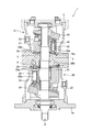
- FIG. 1 is a front view of a fluid pressure drive unit according to an embodiment of the present invention.
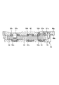
- 2 is a sectional view of the fluid pressure pump motor taken along the line II-II in FIG.
- FIG. 3 is a cross-sectional view of the plate and the power transmission mechanism in FIG.
- hydraulic drive unit 100 as a fluid pressure drive unit according to an embodiment of the present invention will be described with reference to the drawings.
- working oil is used as the working fluid.
- other fluids such as working water may be used as the working fluid instead of the working oil.
- the hydraulic drive unit 100 is driven by supplying hydraulic oil to a hydraulic actuator (not shown) as a fluid pressure actuator.
- the hydraulic drive unit 100 is applied to a hybrid construction machine such as a power shovel that drives a hydraulic actuator with hydraulic oil discharged from a main hydraulic pump (not shown) driven by a prime mover.
- the hydraulic drive unit 100 includes a hydraulic pump 10 as a fluid pressure pump that sucks and discharges hydraulic oil, and a hydraulic motor 20 as a fluid pressure motor that is rotationally driven by the supplied hydraulic oil.
- a hydraulic pump motor 1 as a fluid pressure pump motor is provided.
- the hydraulic drive unit 100 includes an electric motor 30 arranged in parallel with the hydraulic pump motor 1, a plate 40 on which the hydraulic pump motor 1 and the electric motor 30 are mounted on the same surface, and a rotating shaft 2 of the hydraulic pump motor 1. (See FIG. 2) and a power transmission mechanism 50 that transmits power between the rotating shaft (not shown) of the electric motor 30.
- the hydraulic pump 10 and the hydraulic motor 20 constituting the hydraulic pump motor 1 are each a swash plate type variable displacement type piston pump motor.
- the hydraulic motor 20 is a large piston pump motor compared to the hydraulic pump 10.
- the hydraulic pump motor 1 is commonly used by the casing 3 that accommodates the hydraulic pump 10 and the hydraulic motor 20, and rotatably supported by the casing 3. And a single rotating shaft 2.
- the casing 3 has a flange portion 3 a that is bolted to the plate 40.
- the casing 3 includes a supply / discharge passage 4 through which hydraulic oil supplied to the hydraulic pump 10 flows and hydraulic oil discharged from the hydraulic motor 20 flows, a discharge passage 5 through which hydraulic oil discharged from the hydraulic pump 10 flows, and hydraulic pressure And a return passage 6 through which hydraulic oil returned from the actuator and supplied to the hydraulic motor 20 flows.
- the supply / discharge passage 4 communicates with a tank (not shown) in which hydraulic oil is stored.
- the discharge passage 5 and the return passage 6 communicate with the hydraulic actuator.
- the supply / discharge passage 4 is provided to face the discharge passage 5 and the return passage 6.
- the hydraulic pump 10 and the hydraulic motor 20 are arranged to face each other in the axial direction of the rotary shaft 2 with the supply / discharge passage 4, the discharge passage 5, and the return passage 6 interposed therebetween.
- the hydraulic pump 10 sucks hydraulic oil in the supply / discharge passage 4 and discharges it to the discharge passage 5.
- the hydraulic pump 10 assists the drive of the hydraulic actuator by the main hydraulic pump with the discharged hydraulic oil.
- the hydraulic pump 10 includes a cylinder block 11 coupled to the rotary shaft 2, a plurality of pistons 13 respectively accommodated in a plurality of cylinders 12 defined in the cylinder block 11, and a swash plate that reciprocates the pistons 13 that are in sliding contact with each other. 14 and a port plate 15 in which the end face of the cylinder block 11 is in sliding contact.
- the cylinder block 11 is formed in a substantially cylindrical shape and rotates integrally with the rotary shaft 2.
- the cylinder block 11 is rotationally driven by the rotary shaft 2.
- a plurality of cylinders 12 are formed in the cylinder block 11 in parallel with the rotation shaft 2.
- the cylinders 12 are arranged in a ring at regular intervals on the same circumference around the rotation axis 2 of the cylinder block 11.
- a piston 13 is inserted into each cylinder 12, and a volume chamber 12 a is defined between the cylinders 13.
- the volume chamber 12a communicates with the port plate 15 through the communication hole.
- the piston 13 is in sliding contact with the swash plate 14 when the cylinder block 11 rotates together with the rotary shaft 2. Thereby, the piston 13 reciprocates in the cylinder 12 according to the tilt angle of the swash plate 14, and expands and contracts the volume chamber 12a.
- the swash plate 14 is provided such that the tilt angle can be adjusted by a capacity switching actuator (not shown).
- the swash plate 14 can be tilted from a state where the tilt angle perpendicular to the rotation shaft 2 is zero to the state shown in FIG.
- the tilt angle of the swash plate 14 is adjusted steplessly by the capacity switching actuator.
- the port plate 15 is formed in a disc shape, and has a through hole through which the rotary shaft 2 is inserted.
- the port plate 15 is formed in an arc shape centered on the rotation shaft 2 and is formed in an arc shape centered on the rotation shaft 2 and discharged, similarly to the supply port 15a communicating the supply / discharge passage 4 and the volume chamber 12a. It has a discharge port 15b for communicating the passage 5 and the volume chamber 12a.
- a region where the piston 13 slides on the swash plate 14 and the volume chamber 12a expands is a suction region
- a region where the piston 13 slides on the swash plate 14 and the volume chamber 12a contracts is a discharge region.
- the supply port 15a is formed corresponding to the suction area
- the discharge port 15b is formed corresponding to the discharge area.
- the hydraulic motor 20 is rotationally driven by hydraulic oil discharged from the hydraulic actuator.
- the hydraulic motor 20 includes a cylinder block 21 connected to the rotary shaft 2, a plurality of pistons 23 accommodated in a plurality of cylinders 22 defined in the cylinder block 21, and a swash plate that reciprocates the pistons 23 that are in sliding contact with each other. 24 and a port plate 25 in which the end face of the cylinder block 21 is in sliding contact.
- the cylinder block 21, the cylinder 22, the piston 23, and the swash plate 24 of the hydraulic motor 20 have the same configuration except for the configuration of the hydraulic pump 10 described above, and thus the description thereof is omitted here.
- the port plate 25 is formed in a disc shape and has a through hole through which the rotary shaft 2 is inserted.
- the port plate 25 is formed in an arc shape with the rotation shaft 2 as the center, and the supply port 25a that connects the return passage 6 and the volume chamber 22a. It has a discharge port 25b for communicating the passage 4 and the volume chamber 22a.
- a region where the piston 23 slides on the swash plate 24 and the volume chamber 22a expands is a suction region
- a region where the piston 23 slides on the swash plate 24 and the volume chamber 22a contracts is a discharge region.
- the supply port 25a is formed corresponding to the suction area
- the discharge port 25b is formed corresponding to the discharge area.
- the electric motor 30 can drive the hydraulic pump 10 to rotate and can generate regenerative power by the rotation of the hydraulic motor 20.
- the electric power generated by the electric motor 30 is stored in a power storage device (not shown).
- the electric motor 30 rotationally drives the hydraulic pump 10 using the regenerative power regenerated by the rotation of the hydraulic motor 20 and stored in the power storage device.
- the plate 40 is a plate-like member in which the hydraulic pump motor 1 and the electric motor 30 are attached to one surface 40 a and the casing 51 of the power transmission mechanism 50 is attached to the other surface 40 b.
- the power transmission mechanism 50 is provided to face the hydraulic pump motor 1 and the electric motor 30 with the plate 40 interposed therebetween.
- the plate 40 is formed with a through hole (not shown) through which the rotary shaft 2 of the hydraulic pump motor 1 passes and a through hole (not shown) through which the rotary shaft of the electric motor 30 passes.
- the hydraulic pump motor 1 and the electric motor 30 are arranged in a U shape via the plate 40 and the power transmission mechanism 50. Therefore, the total length of the hydraulic drive unit 100 can be shortened by the amount that the hydraulic pump motor 1 and the electric motor 30 are arranged in parallel. Therefore, the mountability of the hydraulic drive unit 100 on the hybrid construction machine can be improved.
- the power transmission mechanism 50 includes a casing 51 fixed to the plate 40, a first gear 52 that rotates integrally with the rotating shaft 2 of the hydraulic pump motor 1, and a rotating shaft of the electric motor 30.
- a rotating second gear 53 and an idle gear 54 provided between the first gear 52 and the second gear 53 for transmitting power are provided.
- the casing 51 accommodates a first gear 52, a second gear 53, and an idle gear 54.
- the casing 51 is bolted in a state where the open end surface 51 a is in contact with the other surface 40 b of the plate 40.
- the casing 51 is filled with lubricating oil.
- the first gear 52 has a recess 52a formed on the rotating shaft and into which the rotating shaft 2 of the hydraulic pump motor 1 is fitted. Thereby, the first gear 52 rotates integrally with the rotary shaft 2 of the hydraulic pump motor 1.
- one end of the rotating shaft is rotatably supported on the plate 40 by the first bearing 52b, and the other end of the rotating shaft is rotatably supported on the casing 51 by the second bearing 52c.
- the second gear 53 has a concave portion 53a formed on the rotation shaft and into which the rotation shaft of the electric motor 30 is inserted. As a result, the second gear 53 rotates integrally with the rotating shaft of the electric motor 30.
- one end of the rotating shaft is rotatably supported on the plate 40 by the first bearing 53b, and the other end of the rotating shaft is rotatably supported on the casing 51 by the second bearing 53c.
- the idle gear 54 meshes with each of the first gear 52 and the second gear 53 to transmit power to each other.
- one end of a rotating shaft is rotatably supported on the plate 40 by a first bearing 54b, and the other end of the rotating shaft is rotatably supported on the casing 51 by a second bearing 54c.
- the power transmission mechanism 50 can be reduced in size, and the entire hydraulic drive unit 100 can be reduced in size.
- the reduction ratio between the hydraulic pump motor 1 and the electric motor 30 can be set to an appropriate value.
- the electric motor 30 rotates using the electric power previously stored in the power storage device.
- the rotation shaft 2 of the hydraulic pump motor 1 is rotationally driven via the power transmission mechanism 50 by the rotation of the electric motor 30.
- the hydraulic pump 10 is switched to a predetermined value in which the tilt angle of the swash plate 14 is larger than zero by the capacity switching actuator.
- the piston 13 reciprocates in the cylinder 12 as the cylinder block 11 rotates.
- the hydraulic oil from the tank is sucked into the volume chamber 12 a through the supply port 15 a of the port plate 15.
- the hydraulic oil discharged from the volume chamber 12 a is guided to the discharge passage 5 through the discharge port 15 b of the port plate 15.
- the hydraulic oil discharged from the hydraulic drive unit 100 is used for driving the hydraulic actuator, and assists the drive of the hydraulic actuator by the main hydraulic pump.
- the hydraulic motor 20 is held by the capacity switching actuator so that the tilt angle of the swash plate 24 becomes zero. Therefore, since the piston 23 does not reciprocate in the cylinder 22, the displacement volume by the piston 23 becomes zero. Accordingly, since the hydraulic motor 20 only idles without supplying or discharging the hydraulic oil, the drive loss of the hydraulic motor 20 can be suppressed.
- the hydraulic motor 20 when regenerative electric power is generated by the hydraulic oil discharged from the hydraulic actuator, the hydraulic motor 20 is switched to a predetermined value in which the inclination angle of the swash plate 24 is larger than zero by the capacity switching actuator.
- the piston 23 reciprocates in the cylinder 22 as the cylinder block 21 rotates. Due to the reciprocating motion of the piston 23, the pressurized hydraulic fluid that has returned from the hydraulic actuator through the return passage 6 flows into the volume chamber 22 a through the supply port 25 a of the port plate 25. Then, the piston 23 reciprocates in the cylinder 22 to rotationally drive the cylinder block 21.
- the hydraulic oil that has flowed into the volume chamber 22a is discharged to the supply / discharge passage 4 through the discharge port 25b of the port plate 25 and is returned to the tank.
- Rotating shaft 2 rotates integrally with cylinder block 21.
- the rotation of the rotating shaft 2 is transmitted to the rotating shaft of the electric motor 30 via the power transmission mechanism 50.
- the electric motor 30 can generate regenerative power and store it in the power storage device.
- the hydraulic pump 10 is held by the displacement switching actuator so that the tilt angle of the swash plate 14 becomes zero. Therefore, since the piston 13 does not reciprocate within the cylinder 12, the displacement volume by the piston 13 becomes zero. Therefore, since the hydraulic pump 10 merely idles without supplying or discharging the hydraulic oil, the drive loss of the hydraulic pump 10 can be suppressed.
- the hydraulic drive unit 100 assists the supply of hydraulic oil to the plurality of hydraulic actuators by the main hydraulic pump, the hydraulic drive unit 100 assists the drive of one hydraulic actuator and the hydraulic oil is recirculated from the other hydraulic actuators. There is also a case.
- the hydraulic pump motor 1 and the electric motor 30 are arranged in parallel and attached to the plate 40, and the power transmission mechanism 50 transmits power between the rotary shaft 2 of the hydraulic pump motor 1 and the rotary shaft of the electric motor 30. Therefore, the total length of the hydraulic drive unit 100 can be shortened by the amount that the hydraulic pump motor 1 and the electric motor 30 are arranged in parallel. Therefore, the mountability of the hydraulic drive unit 100 can be improved.
- the idle gear 54 is provided between the first gear 52 and the second gear 53, so that the first gear 52 and the second gear 53 can be reduced in diameter. Therefore, even when the distance between the hydraulic pump motor 1 and the electric motor 30 is relatively long, the first gear 52 and the second gear 53 are prevented from becoming large in diameter. Therefore, the power transmission mechanism 50 can be reduced in size, and the entire hydraulic drive unit 100 can be reduced in size.
- the hydraulic drive unit 100 assists the drive of the hydraulic actuator by the main hydraulic pump, but instead of this, the hydraulic actuator may be driven using only the hydraulic drive unit 100.
- both the hydraulic pump 10 and the hydraulic motor 20 are swash plate type piston pump motors, but other types may be used as long as they are variable displacement types capable of adjusting the suction / discharge capacity to zero.
Landscapes
- Engineering & Computer Science (AREA)
- General Engineering & Computer Science (AREA)
- Mechanical Engineering (AREA)
- Fluid Mechanics (AREA)
- Physics & Mathematics (AREA)
- Chemical & Material Sciences (AREA)
- Analytical Chemistry (AREA)
- Civil Engineering (AREA)
- Structural Engineering (AREA)
- Mining & Mineral Resources (AREA)
- Combustion & Propulsion (AREA)
- Reciprocating Pumps (AREA)
- Hydraulic Motors (AREA)
- Fluid-Pressure Circuits (AREA)
- Operation Control Of Excavators (AREA)
- Electromagnetic Pumps, Or The Like (AREA)
Abstract
Description
Claims (5)
- 流体圧アクチュエータに作動流体を供給して駆動する流体圧駆動ユニットであって、
作動流体を吸い込んで吐出する流体圧ポンプと、
前記流体圧ポンプと並列に並べて配置され、前記流体圧ポンプを回転駆動する電動機と、
前記流体圧ポンプの回転軸と前記電動機の回転軸との間で動力を伝達する動力伝達機構と、を備える流体圧駆動ユニット。 - 請求項1に記載の流体圧駆動ユニットであって、
前記流体圧ポンプと前記電動機とが同一の面に取り付けられ、前記流体圧ポンプの回転軸と前記電動機の回転軸とが貫通するプレートを更に備える流体圧駆動ユニット。 - 請求項1に記載の流体圧駆動ユニットであって、
前記動力伝達機構は、
前記流体圧ポンプの回転軸と一体に回転する第一ギアと、
前記電動機の回転軸と一体に回転する第二ギアと、
前記第一ギアと前記第二ギアの間に設けられて動力を伝達するアイドルギアと、を備える流体圧駆動ユニット。 - 請求項1に記載の流体圧駆動ユニットであって、
前記流体圧ポンプの回転軸と共通の回転軸を用い、供給される作動流体によって回転駆動される流体圧モータを更に備え、
前記電動機は、前記流体圧モータの回転によって回生電力を発電可能である流体圧駆動ユニット。 - 請求項4に記載の流体圧駆動ユニットであって、
原動機で駆動されるメイン流体圧ポンプから吐出される作動流体によって前記流体圧アクチュエータを駆動するハイブリッド建設機械に適用され、
前記流体圧モータは、前記流体圧アクチュエータから排出された作動流体によって回転駆動され、
前記電動機は、前記流体圧モータの回転によって回生電力を発電するとともに、その回生電力を使用して前記流体圧ポンプを回転駆動し、
前記流体圧ポンプは、吐出した作動流体によって前記メイン流体圧ポンプによる前記流体圧アクチュエータの駆動をアシストする流体圧駆動ユニット。
Priority Applications (4)
| Application Number | Priority Date | Filing Date | Title |
|---|---|---|---|
| EP13769450.1A EP2848809A4 (en) | 2012-03-29 | 2013-03-22 | LIQUID PRESSURE DRIVE UNIT |
| CN201380017676.5A CN104220749A (zh) | 2012-03-29 | 2013-03-22 | 流体压驱动单元 |
| KR1020147026742A KR20140126405A (ko) | 2012-03-29 | 2013-03-22 | 유체압 구동 유닛 |
| US14/389,290 US20150059328A1 (en) | 2012-03-29 | 2013-03-22 | Fluid pressure drive unit |
Applications Claiming Priority (2)
| Application Number | Priority Date | Filing Date | Title |
|---|---|---|---|
| JP2012075527A JP5934543B2 (ja) | 2012-03-29 | 2012-03-29 | 流体圧駆動ユニット |
| JP2012-075527 | 2012-03-29 |
Publications (1)
| Publication Number | Publication Date |
|---|---|
| WO2013146575A1 true WO2013146575A1 (ja) | 2013-10-03 |
Family
ID=49259830
Family Applications (1)
| Application Number | Title | Priority Date | Filing Date |
|---|---|---|---|
| PCT/JP2013/058253 Ceased WO2013146575A1 (ja) | 2012-03-29 | 2013-03-22 | 流体圧駆動ユニット |
Country Status (6)
| Country | Link |
|---|---|
| US (1) | US20150059328A1 (ja) |
| EP (1) | EP2848809A4 (ja) |
| JP (1) | JP5934543B2 (ja) |
| KR (1) | KR20140126405A (ja) |
| CN (1) | CN104220749A (ja) |
| WO (1) | WO2013146575A1 (ja) |
Families Citing this family (11)
| Publication number | Priority date | Publication date | Assignee | Title |
|---|---|---|---|---|
| JP5860695B2 (ja) * | 2011-12-28 | 2016-02-16 | Kyb株式会社 | 電動オイルポンプ |
| JP5767996B2 (ja) * | 2012-03-29 | 2015-08-26 | カヤバ工業株式会社 | 流体圧駆動ユニット |
| EP3020969B1 (en) * | 2014-11-11 | 2017-09-27 | Danfoss A/S | Pump arrangement |
| EP3020967B1 (en) * | 2014-11-11 | 2017-09-27 | Danfoss A/S | Pump device |
| US9840143B1 (en) | 2015-05-20 | 2017-12-12 | Hydro-Gear Limited Partnership | Cooling pump assembly and cooling system for utility vehicle |
| US10358040B1 (en) | 2015-06-01 | 2019-07-23 | Hydro-Gear Limited Partnership | Drive assembly and system for utility vehicle |
| US10106027B1 (en) | 2015-06-01 | 2018-10-23 | Hydro-Gear Limited Partnership | Generator/cooling assembly and system for utility vehicle |
| US10391854B1 (en) | 2015-06-15 | 2019-08-27 | Hydro-Gear Limited Partnership | Drive and cooling system for utility vehicle |
| US10093169B1 (en) | 2015-07-09 | 2018-10-09 | Hydro-Gear Limited Partnership | Power and cooling system for utility vehicle |
| CA3002566A1 (en) * | 2015-11-25 | 2017-06-01 | Kinetics Drive Solutions Inc. | Load cancelling hydrostatic system |
| DE102018113677A1 (de) * | 2018-06-08 | 2019-12-12 | Dr. Ing. H.C. F. Porsche Aktiengesellschaft | KFZ-Pumpenanordnung |
Citations (5)
| Publication number | Priority date | Publication date | Assignee | Title |
|---|---|---|---|---|
| JPH11303724A (ja) * | 1998-04-20 | 1999-11-02 | Nagatomo Ryutai Kikai Kenkyusho:Kk | 電動油圧複合変速装置 |
| WO2009110043A1 (ja) * | 2008-03-03 | 2009-09-11 | 株式会社カワサキプレシジョンマシナリ | 電動機一体型油圧モータ |
| JP2010142086A (ja) * | 2008-12-15 | 2010-06-24 | Toshiba Mach Co Ltd | 油圧電動ハイブリッド型モータおよび同モータを組み込んだ旋回駆動機構を有する油圧ショベル |
| JP2011127569A (ja) | 2009-12-21 | 2011-06-30 | Kyb Co Ltd | アシスト回生装置 |
| WO2012023231A1 (ja) * | 2010-08-18 | 2012-02-23 | 川崎重工業株式会社 | 作業機械の電液駆動システム |
Family Cites Families (50)
| Publication number | Priority date | Publication date | Assignee | Title |
|---|---|---|---|---|
| US3102487A (en) * | 1962-06-26 | 1963-09-03 | Dow Chemical Co | Pumping apparatus |
| US3103890A (en) * | 1962-06-26 | 1963-09-17 | Dow Chemical Co | Variable output pumping means |
| US3165062A (en) * | 1963-07-29 | 1965-01-12 | Dow Chemical Co | Variable volume pumping apparatus |
| US3162131A (en) * | 1963-07-29 | 1964-12-22 | Dow Chemical Co | Pumping appartus |
| US3161136A (en) * | 1963-07-29 | 1964-12-15 | Dow Chemical Co | Variable volume pumping apparatus |
| JP2613051B2 (ja) * | 1987-05-07 | 1997-05-21 | カヤバ工業株式会社 | ギヤポンプ |
| IT1248038B (it) * | 1991-06-11 | 1995-01-05 | Siti | Dispositivo per alimentare liquido sotto pressione a un circuito idraulico. |
| US5251534A (en) * | 1992-04-29 | 1993-10-12 | Kayaba Industry Co. Ltd. | Input apparatus |
| US5507317A (en) * | 1992-04-29 | 1996-04-16 | Kayaba Industry Co., Ltd. | Input apparatus |
| US7083397B1 (en) * | 1998-06-04 | 2006-08-01 | Scroll Technologies | Scroll compressor with motor control for capacity modulation |
| DE19831624A1 (de) * | 1998-07-15 | 2000-01-20 | Mueller Weingarten Maschf | Hydraulischer Antrieb für eine Presse |
| JP2000055752A (ja) * | 1998-08-03 | 2000-02-25 | Kayaba Ind Co Ltd | トルク検出装置 |
| ATE288633T1 (de) * | 1999-08-10 | 2005-02-15 | Swatch Group Man Serv Ag | Antriebsvorrichtung mit einem flüssigkeitsgekühlten elektrischen motor und planetengetriebe |
| DE10000765A1 (de) * | 2000-01-11 | 2001-07-26 | Sauer Sundstrand Gmbh & Co | Schmierungseinrichtung zur Schmierung hydraulischer Bauteile und hydrostatisches Getriebe mit Schmierungseinrichtung |
| US6834737B2 (en) * | 2000-10-02 | 2004-12-28 | Steven R. Bloxham | Hybrid vehicle and energy storage system and method |
| US6460333B2 (en) * | 2000-12-22 | 2002-10-08 | Caterpillar Inc. | Hydraulic pressure transformer |
| US6644939B2 (en) * | 2001-08-17 | 2003-11-11 | Borgwarner, Inc. | Method and apparatus for providing a hydraulic transmission pump assembly having a differential actuation |
| JP4173345B2 (ja) * | 2002-10-03 | 2008-10-29 | 本田技研工業株式会社 | 車両の駆動装置 |
| DE10304121A1 (de) * | 2003-01-31 | 2004-08-12 | Voith Turbo Gmbh & Co. Kg | Motorpumpenaggregat |
| JP2004278381A (ja) * | 2003-03-14 | 2004-10-07 | Toyota Industries Corp | ギヤポンプ |
| US7086981B2 (en) * | 2004-02-18 | 2006-08-08 | The Gates Corporation | Transmission and constant speed accessory drive |
| CH701073B1 (de) * | 2004-07-22 | 2010-11-30 | Siegfried A Dipl-Ing Eisenmann | Hydrostatischer Kreiskolbenmotor. |
| JP2006125209A (ja) * | 2004-10-26 | 2006-05-18 | Kayaba Ind Co Ltd | Cvt用ベーンポンプ |
| JP2006183499A (ja) * | 2004-12-27 | 2006-07-13 | Hitachi Ltd | 容積形圧縮機 |
| WO2006090483A1 (ja) * | 2005-02-24 | 2006-08-31 | Aisin Aw Co., Ltd. | 歯車ポンプおよびこれを用いた自動変速機用オイルポンプ |
| EP1705372A1 (en) * | 2005-03-11 | 2006-09-27 | Innas B.V. | Variable pump or hydraulic motor |
| DE102005016884A1 (de) * | 2005-04-12 | 2006-10-19 | Wirth Maschinen- und Bohrgeräte-Fabrik GmbH | Pumpensystem |
| US7870733B2 (en) * | 2005-12-21 | 2011-01-18 | Denso Corporation | Fluid machine for rankine cycle |
| DE102006008430A1 (de) * | 2006-02-23 | 2007-08-30 | Zf Friedrichshafen Ag | Antriebseinrichtung für die Ölpumpe eines Kraftfahrzeuggetriebes |
| US7669414B2 (en) * | 2006-03-28 | 2010-03-02 | Parker-Hannifin Corporation | Hydraulic energy recovery system with dual-powered auxiliary hydraulics |
| DE102006026631B4 (de) * | 2006-06-08 | 2011-06-22 | ZF Friedrichshafen AG, 88046 | Vorrichtung zum Antrieb einer Ölpumpe |
| JP4888158B2 (ja) * | 2007-02-28 | 2012-02-29 | 株式会社ジェイテクト | 電動ポンプユニット及び電動オイルポンプ |
| JP2008232018A (ja) * | 2007-03-20 | 2008-10-02 | Kubota Corp | ポンプ装置 |
| US7758320B2 (en) * | 2007-05-03 | 2010-07-20 | Tank, Inc. | Two-stage hydrodynamic pump and method |
| US7634911B2 (en) * | 2007-06-29 | 2009-12-22 | Caterpillar Inc. | Energy recovery system |
| US8187136B2 (en) * | 2007-09-28 | 2012-05-29 | Musashi Seimitsu Industry Co., Ltd. | Differential gear |
| JP2009097485A (ja) * | 2007-10-19 | 2009-05-07 | Mitsubishi Heavy Ind Ltd | 圧縮機 |
| DE602008004099D1 (de) * | 2008-04-29 | 2011-02-03 | Parker Hannifin Ab | Anordnung zum Bedienen einer hydraulischen Vorrichtung |
| US8016576B2 (en) * | 2008-08-02 | 2011-09-13 | Ford Global Technologies, Llc | Vehicle transmission with fluid pump having a recirculation circuit |
| JP5334719B2 (ja) * | 2009-07-10 | 2013-11-06 | カヤバ工業株式会社 | ハイブリッド建設機械の制御装置 |
| EP2479351A4 (en) * | 2009-09-15 | 2017-07-05 | Sumitomo Heavy Industries, LTD. | Hybrid construction machine |
| JP5401251B2 (ja) * | 2009-10-07 | 2014-01-29 | 日立建機株式会社 | 建設機械 |
| JP5500003B2 (ja) * | 2010-08-31 | 2014-05-21 | 株式会社アドヴィックス | 回転式ポンプ装置 |
| JP5297429B2 (ja) * | 2010-09-24 | 2013-09-25 | アイシン・エィ・ダブリュ株式会社 | 液圧発生装置及び駆動装置 |
| JP5325188B2 (ja) * | 2010-09-24 | 2013-10-23 | アイシン・エィ・ダブリュ株式会社 | 液圧発生装置及び駆動装置 |
| KR102015094B1 (ko) * | 2012-01-04 | 2019-08-27 | 파커-한니핀 코포레이션 | 선회 구동 시스템 |
| CN103998784B (zh) * | 2012-03-26 | 2015-08-05 | 萱场工业株式会社 | 流体压泵马达 |
| JP5767996B2 (ja) * | 2012-03-29 | 2015-08-26 | カヤバ工業株式会社 | 流体圧駆動ユニット |
| EP2746590B1 (en) * | 2012-12-19 | 2016-03-09 | Bucher Hydraulics S.p.A. | Power unit to move at least a hydraulic actuator |
| CN105408151A (zh) * | 2013-03-15 | 2016-03-16 | 储存能源解决方案公司 | 液压混合系统 |
-
2012
- 2012-03-29 JP JP2012075527A patent/JP5934543B2/ja active Active
-
2013
- 2013-03-22 US US14/389,290 patent/US20150059328A1/en not_active Abandoned
- 2013-03-22 KR KR1020147026742A patent/KR20140126405A/ko not_active Ceased
- 2013-03-22 CN CN201380017676.5A patent/CN104220749A/zh active Pending
- 2013-03-22 EP EP13769450.1A patent/EP2848809A4/en not_active Withdrawn
- 2013-03-22 WO PCT/JP2013/058253 patent/WO2013146575A1/ja not_active Ceased
Patent Citations (5)
| Publication number | Priority date | Publication date | Assignee | Title |
|---|---|---|---|---|
| JPH11303724A (ja) * | 1998-04-20 | 1999-11-02 | Nagatomo Ryutai Kikai Kenkyusho:Kk | 電動油圧複合変速装置 |
| WO2009110043A1 (ja) * | 2008-03-03 | 2009-09-11 | 株式会社カワサキプレシジョンマシナリ | 電動機一体型油圧モータ |
| JP2010142086A (ja) * | 2008-12-15 | 2010-06-24 | Toshiba Mach Co Ltd | 油圧電動ハイブリッド型モータおよび同モータを組み込んだ旋回駆動機構を有する油圧ショベル |
| JP2011127569A (ja) | 2009-12-21 | 2011-06-30 | Kyb Co Ltd | アシスト回生装置 |
| WO2012023231A1 (ja) * | 2010-08-18 | 2012-02-23 | 川崎重工業株式会社 | 作業機械の電液駆動システム |
Non-Patent Citations (1)
| Title |
|---|
| See also references of EP2848809A4 * |
Also Published As
| Publication number | Publication date |
|---|---|
| EP2848809A1 (en) | 2015-03-18 |
| JP2013204536A (ja) | 2013-10-07 |
| EP2848809A4 (en) | 2016-03-30 |
| US20150059328A1 (en) | 2015-03-05 |
| KR20140126405A (ko) | 2014-10-30 |
| CN104220749A (zh) | 2014-12-17 |
| JP5934543B2 (ja) | 2016-06-15 |
Similar Documents
| Publication | Publication Date | Title |
|---|---|---|
| JP5934543B2 (ja) | 流体圧駆動ユニット | |
| JP5767996B2 (ja) | 流体圧駆動ユニット | |
| US10519990B2 (en) | Hydraulic apparatus | |
| JP5600274B2 (ja) | 作業機械の電液駆動システム | |
| CN100455800C (zh) | 阀板以及具备阀板的液压装置 | |
| US20100107866A1 (en) | Three speed floating cup hydraulic motor | |
| JP5608833B2 (ja) | 流体圧ポンプモータ | |
| US20240337256A1 (en) | Electro-hydraulic apparatus, and vehicle comprising electro-hydraulic apparatus | |
| JP7631072B2 (ja) | 駆動装置及び建設機械 | |
| JP2004278602A (ja) | 油圧式無段変速機 | |
| JP2006057606A (ja) | 建設機械におけるポンプ駆動機構 | |
| JP5713493B2 (ja) | 斜板式ピストンポンプ | |
| KR101867529B1 (ko) | 피스톤 펌프 | |
| JPS63203959A (ja) | 斜板式油圧装置の作動油分配装置 | |
| JP2014105620A (ja) | 油圧装置 | |
| JP2009127484A (ja) | ラジアルピストンポンプ及びそれを用いた動力伝達装置、並びにラジアルピストンモータ | |
| JP2004100564A (ja) | 油圧ポンプ | |
| JP2001140748A (ja) | タンデム型油圧ポンプ | |
| CN108351006B (zh) | 载荷消除流体静压系统 |
Legal Events
| Date | Code | Title | Description |
|---|---|---|---|
| 121 | Ep: the epo has been informed by wipo that ep was designated in this application |
Ref document number: 13769450 Country of ref document: EP Kind code of ref document: A1 |
|
| ENP | Entry into the national phase |
Ref document number: 20147026742 Country of ref document: KR Kind code of ref document: A |
|
| WWE | Wipo information: entry into national phase |
Ref document number: 14389290 Country of ref document: US |
|
| REEP | Request for entry into the european phase |
Ref document number: 2013769450 Country of ref document: EP |
|
| WWE | Wipo information: entry into national phase |
Ref document number: 2013769450 Country of ref document: EP |
|
| NENP | Non-entry into the national phase |
Ref country code: DE |