WO2013146725A1 - 生体光計測装置、生体光計測方法および移動型位置センサ用係合部材 - Google Patents
生体光計測装置、生体光計測方法および移動型位置センサ用係合部材 Download PDFInfo
- Publication number
- WO2013146725A1 WO2013146725A1 PCT/JP2013/058673 JP2013058673W WO2013146725A1 WO 2013146725 A1 WO2013146725 A1 WO 2013146725A1 JP 2013058673 W JP2013058673 W JP 2013058673W WO 2013146725 A1 WO2013146725 A1 WO 2013146725A1
- Authority
- WO
- WIPO (PCT)
- Prior art keywords
- optical fiber
- subject
- measurement
- tip
- biological light
- Prior art date
- Legal status (The legal status is an assumption and is not a legal conclusion. Google has not performed a legal analysis and makes no representation as to the accuracy of the status listed.)
- Ceased
Links
- 0 CCC*(C(C)C*(CC)C1)[C@]11*CC*C1 Chemical compound CCC*(C(C)C*(CC)C1)[C@]11*CC*C1 0.000 description 1
Images












Classifications
-
- A—HUMAN NECESSITIES
- A61—MEDICAL OR VETERINARY SCIENCE; HYGIENE
- A61B—DIAGNOSIS; SURGERY; IDENTIFICATION
- A61B5/00—Measuring for diagnostic purposes; Identification of persons
- A61B5/145—Measuring characteristics of blood in vivo, e.g. gas concentration or pH-value ; Measuring characteristics of body fluids or tissues, e.g. interstitial fluid or cerebral tissue
- A61B5/1455—Measuring characteristics of blood in vivo, e.g. gas concentration or pH-value ; Measuring characteristics of body fluids or tissues, e.g. interstitial fluid or cerebral tissue using optical sensors, e.g. spectral photometrical oximeters
- A61B5/14551—Measuring characteristics of blood in vivo, e.g. gas concentration or pH-value ; Measuring characteristics of body fluids or tissues, e.g. interstitial fluid or cerebral tissue using optical sensors, e.g. spectral photometrical oximeters for measuring blood gases
- A61B5/14552—Details of sensors specially adapted therefor
-
- A—HUMAN NECESSITIES
- A61—MEDICAL OR VETERINARY SCIENCE; HYGIENE
- A61B—DIAGNOSIS; SURGERY; IDENTIFICATION
- A61B5/00—Measuring for diagnostic purposes; Identification of persons
- A61B5/0033—Features or image-related aspects of imaging apparatus, e.g. for MRI, optical tomography or impedance tomography apparatus; Arrangements of imaging apparatus in a room
- A61B5/004—Features or image-related aspects of imaging apparatus, e.g. for MRI, optical tomography or impedance tomography apparatus; Arrangements of imaging apparatus in a room adapted for image acquisition of a particular organ or body part
- A61B5/0042—Features or image-related aspects of imaging apparatus, e.g. for MRI, optical tomography or impedance tomography apparatus; Arrangements of imaging apparatus in a room adapted for image acquisition of a particular organ or body part for the brain
-
- A—HUMAN NECESSITIES
- A61—MEDICAL OR VETERINARY SCIENCE; HYGIENE
- A61B—DIAGNOSIS; SURGERY; IDENTIFICATION
- A61B5/00—Measuring for diagnostic purposes; Identification of persons
- A61B5/0059—Measuring for diagnostic purposes; Identification of persons using light, e.g. diagnosis by transillumination, diascopy, fluorescence
- A61B5/0073—Measuring for diagnostic purposes; Identification of persons using light, e.g. diagnosis by transillumination, diascopy, fluorescence by tomography, i.e. reconstruction of 3D images from 2D projections
-
- A—HUMAN NECESSITIES
- A61—MEDICAL OR VETERINARY SCIENCE; HYGIENE
- A61B—DIAGNOSIS; SURGERY; IDENTIFICATION
- A61B5/00—Measuring for diagnostic purposes; Identification of persons
- A61B5/02—Detecting, measuring or recording for evaluating the cardiovascular system, e.g. pulse, heart rate, blood pressure or blood flow
- A61B5/02028—Determining haemodynamic parameters not otherwise provided for, e.g. cardiac contractility or left ventricular ejection fraction
-
- A—HUMAN NECESSITIES
- A61—MEDICAL OR VETERINARY SCIENCE; HYGIENE
- A61B—DIAGNOSIS; SURGERY; IDENTIFICATION
- A61B5/00—Measuring for diagnostic purposes; Identification of persons
- A61B5/02—Detecting, measuring or recording for evaluating the cardiovascular system, e.g. pulse, heart rate, blood pressure or blood flow
- A61B5/026—Measuring blood flow
- A61B5/0261—Measuring blood flow using optical means, e.g. infrared light
-
- A—HUMAN NECESSITIES
- A61—MEDICAL OR VETERINARY SCIENCE; HYGIENE
- A61B—DIAGNOSIS; SURGERY; IDENTIFICATION
- A61B5/00—Measuring for diagnostic purposes; Identification of persons
- A61B5/02—Detecting, measuring or recording for evaluating the cardiovascular system, e.g. pulse, heart rate, blood pressure or blood flow
- A61B5/026—Measuring blood flow
- A61B5/0295—Measuring blood flow using plethysmography, i.e. measuring the variations in the volume of a body part as modified by the circulation of blood therethrough, e.g. impedance plethysmography
-
- A—HUMAN NECESSITIES
- A61—MEDICAL OR VETERINARY SCIENCE; HYGIENE
- A61B—DIAGNOSIS; SURGERY; IDENTIFICATION
- A61B5/00—Measuring for diagnostic purposes; Identification of persons
- A61B5/06—Devices, other than using radiation, for detecting or locating foreign bodies ; Determining position of diagnostic devices within or on the body of the patient
- A61B5/061—Determining position of a probe within the body employing means separate from the probe, e.g. sensing internal probe position employing impedance electrodes on the surface of the body
- A61B5/062—Determining position of a probe within the body employing means separate from the probe, e.g. sensing internal probe position employing impedance electrodes on the surface of the body using magnetic field
-
- A—HUMAN NECESSITIES
- A61—MEDICAL OR VETERINARY SCIENCE; HYGIENE
- A61B—DIAGNOSIS; SURGERY; IDENTIFICATION
- A61B5/00—Measuring for diagnostic purposes; Identification of persons
- A61B5/145—Measuring characteristics of blood in vivo, e.g. gas concentration or pH-value ; Measuring characteristics of body fluids or tissues, e.g. interstitial fluid or cerebral tissue
- A61B5/1455—Measuring characteristics of blood in vivo, e.g. gas concentration or pH-value ; Measuring characteristics of body fluids or tissues, e.g. interstitial fluid or cerebral tissue using optical sensors, e.g. spectral photometrical oximeters
- A61B5/14551—Measuring characteristics of blood in vivo, e.g. gas concentration or pH-value ; Measuring characteristics of body fluids or tissues, e.g. interstitial fluid or cerebral tissue using optical sensors, e.g. spectral photometrical oximeters for measuring blood gases
- A61B5/14553—Measuring characteristics of blood in vivo, e.g. gas concentration or pH-value ; Measuring characteristics of body fluids or tissues, e.g. interstitial fluid or cerebral tissue using optical sensors, e.g. spectral photometrical oximeters for measuring blood gases specially adapted for cerebral tissue
-
- A—HUMAN NECESSITIES
- A61—MEDICAL OR VETERINARY SCIENCE; HYGIENE
- A61B—DIAGNOSIS; SURGERY; IDENTIFICATION
- A61B5/00—Measuring for diagnostic purposes; Identification of persons
- A61B5/40—Detecting, measuring or recording for evaluating the nervous system
- A61B5/4058—Detecting, measuring or recording for evaluating the nervous system for evaluating the central nervous system
- A61B5/4064—Evaluating the brain
-
- A—HUMAN NECESSITIES
- A61—MEDICAL OR VETERINARY SCIENCE; HYGIENE
- A61B—DIAGNOSIS; SURGERY; IDENTIFICATION
- A61B2560/00—Constructional details of operational features of apparatus; Accessories for medical measuring apparatus
- A61B2560/04—Constructional details of apparatus
- A61B2560/0406—Constructional details of apparatus specially shaped apparatus housings
- A61B2560/0418—Pen-shaped housings
-
- A—HUMAN NECESSITIES
- A61—MEDICAL OR VETERINARY SCIENCE; HYGIENE
- A61B—DIAGNOSIS; SURGERY; IDENTIFICATION
- A61B2562/00—Details of sensors; Constructional details of sensor housings or probes; Accessories for sensors
- A61B2562/02—Details of sensors specially adapted for in-vivo measurements
- A61B2562/0233—Special features of optical sensors or probes classified in A61B5/00
-
- A—HUMAN NECESSITIES
- A61—MEDICAL OR VETERINARY SCIENCE; HYGIENE
- A61B—DIAGNOSIS; SURGERY; IDENTIFICATION
- A61B2562/00—Details of sensors; Constructional details of sensor housings or probes; Accessories for sensors
- A61B2562/22—Arrangements of medical sensors with cables or leads; Connectors or couplings specifically adapted for medical sensors
- A61B2562/221—Arrangements of sensors with cables or leads, e.g. cable harnesses
- A61B2562/223—Optical cables therefor
-
- A—HUMAN NECESSITIES
- A61—MEDICAL OR VETERINARY SCIENCE; HYGIENE
- A61B—DIAGNOSIS; SURGERY; IDENTIFICATION
- A61B2562/00—Details of sensors; Constructional details of sensor housings or probes; Accessories for sensors
- A61B2562/22—Arrangements of medical sensors with cables or leads; Connectors or couplings specifically adapted for medical sensors
- A61B2562/225—Connectors or couplings
- A61B2562/228—Sensors with optical connectors
-
- A—HUMAN NECESSITIES
- A61—MEDICAL OR VETERINARY SCIENCE; HYGIENE
- A61B—DIAGNOSIS; SURGERY; IDENTIFICATION
- A61B5/00—Measuring for diagnostic purposes; Identification of persons
- A61B5/02—Detecting, measuring or recording for evaluating the cardiovascular system, e.g. pulse, heart rate, blood pressure or blood flow
- A61B5/0205—Simultaneously evaluating both cardiovascular conditions and different types of body conditions, e.g. heart and respiratory condition
-
- A—HUMAN NECESSITIES
- A61—MEDICAL OR VETERINARY SCIENCE; HYGIENE
- A61B—DIAGNOSIS; SURGERY; IDENTIFICATION
- A61B5/00—Measuring for diagnostic purposes; Identification of persons
- A61B5/02—Detecting, measuring or recording for evaluating the cardiovascular system, e.g. pulse, heart rate, blood pressure or blood flow
- A61B5/024—Measuring pulse rate or heart rate
- A61B5/02416—Measuring pulse rate or heart rate using photoplethysmograph signals, e.g. generated by infrared radiation
-
- A—HUMAN NECESSITIES
- A61—MEDICAL OR VETERINARY SCIENCE; HYGIENE
- A61B—DIAGNOSIS; SURGERY; IDENTIFICATION
- A61B5/00—Measuring for diagnostic purposes; Identification of persons
- A61B5/145—Measuring characteristics of blood in vivo, e.g. gas concentration or pH-value ; Measuring characteristics of body fluids or tissues, e.g. interstitial fluid or cerebral tissue
- A61B5/14546—Measuring characteristics of blood in vivo, e.g. gas concentration or pH-value ; Measuring characteristics of body fluids or tissues, e.g. interstitial fluid or cerebral tissue for measuring analytes not otherwise provided for, e.g. ions, cytochromes
-
- A—HUMAN NECESSITIES
- A61—MEDICAL OR VETERINARY SCIENCE; HYGIENE
- A61B—DIAGNOSIS; SURGERY; IDENTIFICATION
- A61B5/00—Measuring for diagnostic purposes; Identification of persons
- A61B5/145—Measuring characteristics of blood in vivo, e.g. gas concentration or pH-value ; Measuring characteristics of body fluids or tissues, e.g. interstitial fluid or cerebral tissue
- A61B5/1455—Measuring characteristics of blood in vivo, e.g. gas concentration or pH-value ; Measuring characteristics of body fluids or tissues, e.g. interstitial fluid or cerebral tissue using optical sensors, e.g. spectral photometrical oximeters
-
- A—HUMAN NECESSITIES
- A61—MEDICAL OR VETERINARY SCIENCE; HYGIENE
- A61B—DIAGNOSIS; SURGERY; IDENTIFICATION
- A61B5/00—Measuring for diagnostic purposes; Identification of persons
- A61B5/68—Arrangements of detecting, measuring or recording means, e.g. sensors, in relation to patient
- A61B5/6801—Arrangements of detecting, measuring or recording means, e.g. sensors, in relation to patient specially adapted to be attached to or worn on the body surface
- A61B5/6802—Sensor mounted on worn items
- A61B5/6803—Head-worn items, e.g. helmets, masks, headphones or goggles
-
- A—HUMAN NECESSITIES
- A61—MEDICAL OR VETERINARY SCIENCE; HYGIENE
- A61B—DIAGNOSIS; SURGERY; IDENTIFICATION
- A61B5/00—Measuring for diagnostic purposes; Identification of persons
- A61B5/68—Arrangements of detecting, measuring or recording means, e.g. sensors, in relation to patient
- A61B5/6801—Arrangements of detecting, measuring or recording means, e.g. sensors, in relation to patient specially adapted to be attached to or worn on the body surface
- A61B5/6813—Specially adapted to be attached to a specific body part
- A61B5/6814—Head
-
- A—HUMAN NECESSITIES
- A61—MEDICAL OR VETERINARY SCIENCE; HYGIENE
- A61B—DIAGNOSIS; SURGERY; IDENTIFICATION
- A61B5/00—Measuring for diagnostic purposes; Identification of persons
- A61B5/68—Arrangements of detecting, measuring or recording means, e.g. sensors, in relation to patient
- A61B5/6801—Arrangements of detecting, measuring or recording means, e.g. sensors, in relation to patient specially adapted to be attached to or worn on the body surface
- A61B5/6844—Monitoring or controlling distance between sensor and tissue
Definitions
- the present invention relates to a biological light measuring device that measures blood circulation, hemodynamics, and hemoglobin change in a living body by irradiating a living body with near infrared light and measuring light that has passed through or reflected inside the living body. It is about.
- the biological light measurement device is a device that irradiates a living body with light having a wavelength from visible to near-infrared through an optical fiber through the scalp, and measures light passing through the living body or reflected inside the living body from the scalp.
- imaging of measurement data by a multi-channel device has been realized (for example, Patent Document 1).
- Patent Document 1 a light irradiation position and a light detection position in a measurement target are measured by a movable position sensor (pen-type magnetic sensor), and a biological light intensity image is superimposed on a head surface image and a brain surface image of the measurement target.
- a biological light measurement device that displays together is disclosed.
- Patent Document 1 since the optical fiber is once removed from the probe holder and the movable position sensor is inserted at the position where the tip of the optical fiber was measured, the tip position before removing the optical fiber is manipulated. Therefore, there is a technical problem that it is impossible to accurately measure the tip position of the optical fiber.
- An object of the present invention is to accurately measure the tip position of an optical fiber in a state where the tip of the optical fiber of the biological light measurement device is in contact with a subject.
- a light irradiation / measurement unit that irradiates a subject with light and measures light that has passed through the subject, and measurement data of the light irradiation / measurement unit are processed to generate a living body.
- a signal processing unit that generates a light measurement image; and a position measurement unit that measures a light irradiation position on the subject of the light irradiation / measurement unit and a position where a passing light is extracted from the subject.
- the measurement unit includes a plurality of optical fibers, a plurality of optical fiber plugs attached to the plurality of optical fibers, and a holder that is detachably fixed to a measurement site of a subject and holds the plurality of optical fiber plugs.
- the position measuring unit includes: a movable position sensor; and an engagement member attached to the movable position sensor and detachably engaged with the plurality of optical fiber plugs held by the holder. It has.
- the position of the distal end portion of the optical fiber is measured in a state where the distal end of the optical fiber is in contact with the subject without removing the optical fiber and the optical fiber plug of the biological light measurement device from the holder. be able to.
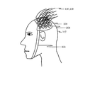
- the block diagram which shows the whole structure of the biological light measuring device of this invention Side view of subject 107 with holder 108 attached (a), (b) and (c) are a perspective view, a sectional view and a sectional perspective view of the optical fiber plug 204, respectively.
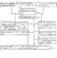
- a flowchart showing a process of the biological light measurement method of the second embodiment Explanatory drawing which shows the superimposition image of pseudomorphic image (wire frame image) 1601 and biological light measurement image 1403 of the subject
- a flowchart showing a process of the biological light measurement method of the third embodiment Explanatory drawing which shows the image which superimposed the form image 1402 of the subject and the tip position 1803 of the attached optical fiber in real time
- Explanatory drawing showing an image in which the form image 1402 of the subject, the tip position 1803 of the attached optical fiber, and the tip position 2004 of the past optical fiber are superimposed in real time (a), (b), and (c) In order to match the positions of the three optical fibers one by one in order, display an error bar indicating the amount of deviation and the direction of movement in order to match the positions of the past optical fibers.
- Explanatory drawing showing an image example Explanatory drawing which shows the example of an image which displays the error bar which shows the amount of deviation, and the direction to move in order to make the position of three optical fibers coincide with the position of the past optical fiber at once.
- 7 is a flowchart showing a process of the biological light measurement method according to the fifth embodiment.
- Explanatory drawing showing an image in which a pseudo form image (wire frame image) 2401 of the subject, the tip position 1803 of the attached optical fiber, and the tip position 2004 of the past optical fiber are superimposed in real time
- the living body light measurement apparatus of the present invention generates a living body light measurement image by irradiating a subject with light and measuring the light irradiation / measurement unit that measures light passing through the subject and the measurement data of the light measurement unit.
- the signal processing unit, and a position measurement unit that measures the light irradiation position on the subject of the light irradiation / measurement unit and the measurement position of the light passing through the subject.
- the light irradiation / measurement unit includes a plurality of optical fibers, an optical fiber plug attached to the optical fiber, and a holder that is detachably fixed to the measurement site of the subject and holds the plurality of optical fiber plugs.
- the position measurement unit includes a movable position sensor, an engagement member attached to the movable position sensor, and a calculation unit.
- the engaging member is detachably engaged with the optical fiber plug held by the holder, the positional relationship between the detection position of the movable position sensor and the surface of the measurement site (hereinafter, this positional relationship is referred to as a predetermined positional relationship). It has a shape.
- the calculating unit calculates the position of the optical fiber tip of the optical fiber plug by calculation from the position detected by the movable position sensor engaged with the optical fiber plug by the engaging member and a predetermined positional relationship.
- the position of the tip of the optical fiber can be measured in a state where the tip of the optical fiber is in contact with the subject without removing the optical fiber and the optical fiber plug from the holder.
- the engaging member has a structure in which the tip of the movable position sensor comes into contact with the end of the fixing portion when engaged with the optical fiber plug.
- the fixed portion is configured to include a cylindrical portion fixed to the optical fiber and a rod-shaped portion fixed to the end portion of the cylindrical portion, and the movable position sensor is configured to have an end of the rod-shaped portion.
- the structure is designed to detect the position of the part.
- the engaging member is configured to have an opening shaped to engage with the outer periphery of the optical fiber plug.
- the opening of the engaging member is formed so that the depth direction is coaxial with the axial direction of the movable position sensor, and the optical fiber of the optical fiber plug inserted into the opening is connected to the axial direction of the movable position sensor. Try to keep it coaxial.
- the calculation unit can obtain the tip position of the optical fiber by calculating a position that is separated from the tip of the movable position sensor by a predetermined distance in the axial direction.
- the optical fiber plug may include a holding portion that holds the fixing portion so as to be movable with respect to the axial direction of the tip portion of the optical fiber.
- the holder can be provided with a plurality of holes for holding the optical fiber plug, the outer periphery of the holding portion of the optical fiber plug can be engaged with the periphery of the hole of the holder, and the optical fiber plug can be attached to the holder.
- the optical fiber may be configured such that the outer periphery of the tip portion is fixed to the fixing portion of the optical fiber plug, bent inside the optical fiber plug, and drawn out from the side surface of the optical fiber plug. In this case, it is preferable to provide a notch into which the optical fiber drawn from the side surface of the optical fiber plug is inserted at the edge of the opening of the engaging member.
- the signal processing unit displays a predetermined display on the display device that prompts the operator to measure the reference region of the subject by attaching a pseudo plug to the engaging member.
- the position measurement unit can be configured to take in the position data of the reference region of the subject measured by the position measurement unit from the position measurement unit.
- the signal processing unit when measuring the tip position of the optical fiber, the signal processing unit removes the pseudo plug from the engaging member and displays on the display device a predetermined display that prompts the operator to measure the tip position of the optical fiber. It is configured to display the position data of the tip of the optical fiber measured by the position measurement unit from the position measurement unit. Then, the signal processing unit adds the captured reference position and the position information of the tip of the optical fiber to the biological light measurement image. Thereby, the signal processing unit can generate an image in which the biological light measurement image is superimposed on the image representing the form of the subject using the position information.
- a biological light measurement method for irradiating a subject with light and measuring the light that has passed through the subject.
- the tips of a plurality of optical fibers to which optical fiber plugs are respectively attached are arranged so as to come into contact with a subject by a holder that holds the plurality of optical fiber plugs.
- the movable position sensor to which the engagement member that can be engaged with the optical fiber plug in a predetermined positional relationship is sequentially engaged with the plurality of optical fiber plugs by the engagement member, and the movable position sensor at that time
- the tip positions of a plurality of optical fibers are obtained by calculation from the detected positions and a predetermined positional relationship.
- the pseudo plug is attached to the engaging member in a predetermined positional relationship, the tip of the pseudo plug is brought into contact with the reference portion of the subject on which the optical fiber plug is not arranged, and the movable position sensor at that time It is also possible to obtain a reference position by calculation from the detection position and a predetermined positional relationship (reference position detection step).
- a display that prompts the operator to attach the pseudo plug to the engaging member can be displayed on the display device.
- a biological light measurement image is generated using data obtained by irradiating light from the optical fiber to the subject, taking the light passing through the subject from the optical fiber, and measuring the biological fiber light using the information on the tip position of the optical fiber. It is also possible to generate an image in which the measurement image is superimposed on an image representing the form of the subject.
- an engagement member attached to a movable position sensor of a biological light measurement device is provided.
- the engaging member has a shape that is detachably engaged with an optical fiber plug attached to the optical fiber of the biological light measuring device in a predetermined positional relationship.
- FIG. 1 is a block diagram of the overall configuration of the biological light measurement device.
- FIG. 2 is a perspective view showing a state in which the optical fibers 106 and 109 are attached to the subject 107.
- the biological light measurement device irradiates near-infrared light into the subject 107, detects light reflected from the surface of the living body or passed through the living body (hereinafter simply referred to as passing light), and corresponds to the light intensity.
- the biological light measurement device includes a light irradiation unit 101 that irradiates near infrared light, a light measurement unit 102 that measures passing light and converts it into an electrical signal, a light irradiation unit 101, and light.
- a control unit 103 that controls driving of the measurement unit 102, a signal processing unit 113, a display device 114, an input / output unit 116, and a storage unit 115 are provided.
- the light irradiation unit 101 includes a semiconductor laser 104 that emits light of a predetermined wavelength, an optical module 105, and an optical fiber 106.
- the optical module 105 includes a modulator for modulating light generated by the semiconductor laser 104 at a plurality of different frequencies for each irradiation position.
- the optical fiber 106 propagates the output light of each optical module 105, guides it to a predetermined measurement region of the subject 107, for example, a plurality of locations on the head, and irradiates the subject 107 from the tip.
- the wavelength of the semiconductor laser 104 depends on the spectral characteristics of the substance of interest in the living body, but when measuring oxygen saturation and blood volume from the oxygenated hemoglobin and deoxygenated hemoglobin concentrations in the blood, the wavelength range is 600 nm to 1400 nm.
- One or more wavelengths are selected from the above light. Specifically, for example, light of two types of wavelengths, for example, 780 nm and 830 nm, is irradiated corresponding to two types of measurement objects, oxygenated hemoglobin and deoxygenated hemoglobin. These two wavelengths of light are combined and irradiated onto the subject 107 from the tip (irradiation position) of one optical fiber 106.
- a sheet-like holder 108 for holding an optical fiber is fixed to the measurement site of the subject 107 by a belt (chin string) 202 or the like.
- the holder 108 is provided with a plurality of holes, and a ring is fixed to the edge of the hole.
- An optical fiber plug 204 is attached to the tip of the optical fiber 106, and the outer periphery of the optical fiber plug 204 is detachably fixed to the holder 108 by engaging with a ring at the edge of the hole.
- the tip of the optical fiber 106 is in contact with the surface of the measurement site of the subject 107 (for example, the scalp).
- the structure of the optical fiber plug 204 will be described in detail later.
- the optical measuring unit 102 includes an optical fiber 109, a photoelectric conversion element 110, a lock-in amplifier module 111, and an A / D converter 112.
- the optical fiber 109 is arranged so that the tip abuts on a predetermined position of the measurement site, and the light emitted from the surface of the subject through the predetermined measurement region out of the light irradiated from the light irradiation unit 101 Is propagated to the photoelectric conversion element 110 from the end face of the tip.
- the photoelectric conversion element is a photodiode or the like that converts light propagated through the optical fiber 109 into an amount of electricity corresponding to the amount of light.
- the lock-in amplifier module 111 selectively detects a modulation signal corresponding to a predetermined light irradiation position among the electric signals from the photoelectric conversion element 110.
- the A / D converter 112 converts the output signal of the lock-in amplifier 111 into a digital signal.
- the amount of hemoglobin changes in the number of channels (2 wavelengths) twice the number of points (measurement points) between the light irradiation position (tip position of the optical fiber 106) and the detection position (tip position of the optical fiber 109). A signal is obtained.
- the signal processing unit 113 processes the hemoglobin amount change signal, and displays a graph showing the oxygenated hemoglobin concentration change, deoxygenated hemoglobin concentration change, total hemoglobin concentration change, etc. for each channel, and a two-dimensional image of the subject.
- the image (biological light measurement image) plotted above is generated.
- the display device 114 displays a graph, an image, or the like generated by the signal processing unit 113.
- the storage unit 115 stores data necessary for processing by the signal processing unit 113, processing results, and generated images.
- the input / output unit 116 receives input of various commands necessary for the operation of the apparatus from the operator.
- the control unit 103 controls the operation of the entire apparatus and causes biological light measurement to be executed.
- the biological light measurement device includes a three-dimensional position measurement unit 117 for measuring the three-dimensional coordinates of the light irradiation position (tip of the optical fiber 106) and the detection position (tip of the optical fiber 109).
- the three-dimensional position measurement unit 117 various measurement methods can be used as long as the three-dimensional position of the movable position sensor can be detected.
- the three-dimensional position measurement unit 117 includes a movable position sensor 118 and a magnetic field generation module 119, and measures the three-dimensional position of the movable position sensor 118 in the magnetic field region 120 generated by the magnetic field generation module 119.
- the optical fiber plug 204 is attached to the distal ends of the optical fibers 106 and 109. By engaging the outer periphery of the optical fiber plug 204 with the ring at the edge of the hole of the holder 108, Removably fixed.
- the structure of the optical fiber plug 204 will be described in detail with reference to FIG. 3A, 3B, and 3C are a perspective view, a cross-sectional view, and a cross-sectional perspective view of the optical fiber plug 204, respectively. Since the optical fiber plug 204 of the optical fiber 106 and the optical fiber plug 204 of the optical fiber 109 have the same structure, the optical fiber plug 204 of the optical fiber 106 will be described below as an example.
- the optical fiber plug 204 is fixed to the cylindrical portion 2603 fixed to the outer periphery near the tip of the optical fiber 106, and fixed to the upper end surface of the cylindrical portion 2603.
- the rod-shaped part 2607 having a predetermined length, a holding part 2602 which is disposed on the outer periphery of the cylindrical part 2603 and holds the cylindrical part 2603 movably in the axial direction, and a spring 2605 are configured.
- the cylindrical portion 2603 and the rod-shaped portion 2607 constitute a fixed portion that is fixed to the optical fiber 106.
- the holding portion 2602 has a shape in which a space is formed inside the cylinder, the tip of the optical fiber 106 protrudes from an opening provided in the lower end surface, and a rod-like portion 2607 protrudes from the opening provided in the upper end surface. .
- the optical fiber 106 is bent in the optical fiber plug 204, pulled out from the opening provided in the side surface of the cylindrical portion 2603, and further drawn out through the opening provided in the side surface of the cylindrical holding portion 2602. ing. Thereby, the axial direction of the tip of the optical fiber 106 is drawn out in a direction bent approximately 90 degrees.
- the cylindrical portion 2603 and the rod-shaped portion 2607 are movable in the axial direction inside the holding portion 2602 integrally with the optical fiber 106. Therefore, the protruding amount of the optical fiber 106 from the holding portion 2602 is variable.
- the spring 2605 is disposed outside the rod-like portion 2607 and urges the cylindrical portion 2603 in a direction of pushing down the upper end surface of the holding portion 2062. By urging the spring 2605, the distal end surface of the optical fiber 106 can be brought into contact with the surface (scalp) of the subject with an appropriate pressing force.
- Threaded protrusions 2604 are provided on the outer periphery at a predetermined pitch at the lower part of the holding portion 2602. The protrusion 2604 engages with a ring fixed to the periphery of the hole of the holder 108, and fixes the optical fiber plug 204 to the holder 108 in a detachable manner.
- the distance 2608 from the upper end of the rod-like member 2607 to the tip of the optical fiber 106 is constant. Therefore, the tip of the optical fiber 106 is obtained by calculating the position at a distance of 2608 in the axial direction by contacting the tip of the movable position sensor 118 with the upper end of the rod-shaped member 2607 and detecting the three-dimensional position. be able to. Since the holding unit 2602 is movable with respect to the optical fiber 106, the distance 2606 from the upper end surface of the holding unit 2602 to the tip of the optical fiber 106 varies depending on the position where the holding unit 2602 is fixed to the holder 108.
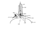
- the optical fiber plug 204 having such a structure is inserted into a hole arranged in the holder 108 as shown in FIG. 2, and the male screw-like protrusion 2604 is engaged with a ring around the hole, thereby allowing light to be emitted.
- the distal end surface of the fiber 106 can be brought into contact with the surface of the subject 108 with a predetermined pressure. At this time, the hair is scraped with a thin stick or the like so that the hair is not caught between the tip of the optical fiber 106 and the surface of the subject 108.
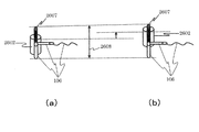
- FIG. 5 schematically shows a state in which the optical fiber plug 204 is fixed to the holder 108 and the tip 306 of the optical fiber 108 is in contact with the surface of the subject 107 as viewed from the cross-sectional direction of the holder 108. is there.
- the optical fiber plugs 204 of all the optical fibers 106 of the light irradiation unit 101 and the optical fiber plugs 204 of all the optical fibers 109 of the light measurement unit 102 are fixed to the holder 108 in a predetermined arrangement.
- the total number of optical fibers 106 and 109 is 30 to 80.
- a screw 2609 is provided on the outer periphery of the upper portion of the holding portion 1602 to connect the cylindrical side member of the holding portion 1602 and the upper end face member. Since the screw 2609 protrudes from the side surface of the holding portion 1602, a recess is formed at a position corresponding to the screw 2609 in the engaging member 502 described later.
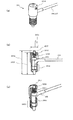
- FIG. 6 (a) is a perspective view of the movable position sensor 118 and a perspective view of parts of the engaging member 502 fixed thereto.
- 6B, 6C, and 6D are a side view, a cross-sectional view, and a cross-sectional perspective view showing a state where the engaging member 502 is fixed to the movable position sensor.
- the movable position sensor 118 is a pen type as shown in FIG. 6 (a), and includes a button 2505 on the side surface.
- the three-dimensional position measurement unit 117 measures the three-dimensional position of the tip of the movable position sensor 118.
- the engaging member 502 is attached to the movable position sensor and has a shape (opening) that is detachably engaged with the optical fiber plug 204 held by the holder 108 in a predetermined positional relationship.
- the engaging member 502 is composed of four parts: a left body part 2502, a right body part 2503, an opening part 2504 that engages with the optical fiber plug 204, and a nut 2505. Since the movable position sensor 118 is a magnetic sensor, each component is made of a non-magnetic material (for example, plastic) that does not generate magnetic noise.
- the left body part 2502, the right body part 2503, and the nut 2505 are members for fixing the opening part 2504 that engages with the optical fiber plug 204 to the movable position sensor 118.
- the left body part 2502 and the right body part 2503 have a space for accommodating the movable position sensor 118 inside, and have a shape that sandwiches the movable position sensor 118.
- the left body part 2502 and the right body part 2503 are formed with threads at the tip and tail ends, and the engagement member 502 is formed by screwing an opening 2504 at the tip and a nut 2505 at the tail end. Are integrally fixed to the movable position sensor.
- the left and right body parts 2502 and 2503 are provided with button holes 2506 at the position of the movable position sensor 118 so that the operator can press the measurement button 2505.
- the opening 2504 is provided with an opening 2511 having a shape that engages with the outer periphery of the holding portion 2602 of the optical fiber plug 204 at the tip. That is, the diameter of the opening 2511 is a size obtained by adding a predetermined clearance to the outer shape of the holding portion 2602.
- the opening 2511 is provided with a notch 2510 having a size capable of inserting the optical fibers 106 and 109 drawn from the side surface of the holding portion 2602. The optical fibers 106 and 109 are inserted into the notch 2508 to be engaged. I try not to get in the way.
- a concave portion having a shape corresponding to the screw 2609 protruding from the side surface of the holding portion 2602 is formed on the inner wall surface of the opening 2511.
- the axial direction of the opening 2504 is set to coincide with the axial direction of the movable position sensor 118.
- the optical fiber plug 204 is engaged (inserted) into the opening 2511 of the opening 2504, whereby the axial direction and the movable position of the tip of the optical fiber 106 are obtained.
- the axial direction of the sensor 118 can be matched.
- a confirmation window 2507 is opened on the side surface of the opening 2504 of the engaging member 502 so that the operator can see the tip of the movable position sensor 118.
- the distal end portion 2705 of the movable position sensor 118 is visually confirmed from the window 2507 while the optical fiber plug 204 is engaged (inserted) into the opening 2511 of the opening portion 2504.
- the engaging member 502 and the movable position sensor 118 can be moved relative to the optical fiber plug 204 until the tip of the rod-like member 2607 of the optical fiber plug 204 comes into contact with the tip 2705 of the movable position sensor 118.
- the three-dimensional position measurement unit 117 measures the position coordinates (x1, y1, z1) of the tip of the movable position sensor 118 and the axial direction vector (dx, dy, dz) of the movable position sensor 118.
- the unit of (x1, y1, z1) is mm
- the unit of (dx, dy, dz) is a dimensionless quantity
- ⁇ (dx2 + dy2 + dz2) 1.
- the signal processing unit 113 reads and executes the built-in program, so that the signal processing unit 113 is located at a position away from the position measured by the three-dimensional position measurement unit 117 by a predetermined distance (L) 2608 in the axial direction of the movable position sensor 118.
- the coordinates (x2, y2, z2) are obtained by calculation using the following formula (1).
- a reference point for example, nadion (nasal root), upper right end of the right ear, upper end of the left ear, etc.
- the optical fiber plug 204 does not exist.
- the work of removing or reattaching the engaging member 502 is not recommended. It is complicated.
- the engagement member 502 when the engagement member 502 is removed, unlike the case where the engagement member 502 is mounted, there is no need to perform the calculation of the signal processing unit 113, and the position obtained by the three-dimensional position measurement unit 117 is determined. Must be used as is. For this reason, the calculation method must be changed depending on whether the reference point is measured or the tips of the optical fibers 106 and 109 are measured, which is complicated.
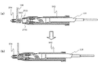
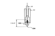
- a pseudo plug 1303 having the same shape and dimensions as the optical fiber plug 204 is inserted into the opening 2511 of the engaging member 502 as shown in FIG.
- the distance L from the front end to the rear end of the pseudo plug 1303 is designed to be the same as the distance 2608 from the front end of the optical fiber 106 to the upper end of the rod-shaped member in FIG.
- the operator can detect the position of the reference point by bringing the tip 1304 of the pseudo plug 1303 into contact with the reference point and pressing the measurement button 2505. Therefore, the complicated operation of removing or attaching the engaging member 502 is not required, and the position of the reference point on the subject can be easily measured without changing the calculation method of the signal processing unit 113.
- the operator sequentially fixes the optical fiber plugs 204 of all the optical fibers 106 and 109 in the holes in the holder 108 so that the tips of the optical fibers 106 and 109 come into contact with the surface of the subject 107 with a predetermined pressure.
- biological light measurement may be performed to generate a biological light measurement image, or biological light measurement may be performed after step 1205.
- the biological light measurement is performed by irradiating the subject 107 with light from the optical fiber 106 of the light irradiating unit 101 under the control of the control unit 103, and capturing and detecting the passing light of the subject 107 through the optical fiber 109. This is performed by generating a biological light measurement image by 113.
- the signal processing unit 113 is displayed on the subject 107 by the movable position sensor 118.
- a message urging to attach a pseudo plug (also referred to as a dummy plug) 1303 to the engaging member (also referred to as a magnetic sensor cover) 502 is displayed on the message window 2802 (step 1208 in FIG. 10). .
- the screen shifts to the screen shown in FIG.
- a display for displaying a position measurement result of a reference point for example, nadion (nasal root), right upper end, left ear upper end, etc.
- An area 2803 is displayed.
- the three-dimensional position measurement unit 117 obtains the position of the movable position sensor 118 at that time, and the signal processing unit 118 Calculates the position of the reference point on the subject by the above-described equation (1) (step 1201).
- the obtained position of the reference point is displayed in the display area 2803 as shown in FIG. 12 (a) and stored in a predetermined area in the storage unit 115. This is repeated until all the reference points are measured.
- the signal processing unit 113 sends a message prompting to remove the pseudo plug 1303 from the engaging member 502 of the movable position sensor 118 as shown in FIG. 12 (b). This is displayed in the window 2804.
- a “Cancel” button on the message window 2804 is pressed, the screen shifts to a screen shown in FIG. 11B, and the position of the reference point on the subject 107 can be measured again.
- step 1201 If the operator removes the pseudo plug 1303 from the engaging member 502 of the movable position sensor 118 according to the message and presses the “OK” button on the message window 2804, the screen shifts to the screen shown in FIG.
- the position measurement of the upper reference point (step 1201) is terminated, and the optical fibers 106 and 109 can be measured by the movable position sensor 118 (step 1205).
- the engagement member 502 is moved so as not to shift the position of the optical fiber plug 204. Approach along the axial direction of the tip of the fiber 106.
- the optical fiber plug 204 is inserted (engaged) into the opening 2511 of the engaging member 502, and the tip of the movable position sensor 118 is brought into contact with the upper end of the rod-shaped member 2607. .
- the operator can visually confirm whether or not they are in contact with each other through the window 2507 of the opening 2504.
- the three-dimensional position measurement unit 117 obtains the position of the movable position sensor 118 at that time, and the signal processing unit 118 uses the optical fiber 106 according to the above equation (1).
- the position of the tip 306 is obtained by calculation (step 1205).
- the obtained position of the tip 306 of the optical fiber 106 is displayed in a display area 2805 in FIG. 13 and stored in a predetermined area in the storage unit 115. This is repeated until all the optical fibers 106 and 109 are measured.
- the signal processing unit 113 reads the morphological image of the subject separately measured (head surface image such as MRI image or CT image of the subject, brain surface image) (step 1202).
- the signal processing unit 103 obtains the position of a reference point (for example, nadion (nasal root), right ear upper end, left ear upper end, etc.) by performing image processing or the like on the captured morphological image (step 1203).
- a reference point for example, nadion (nasal root), right ear upper end, left ear upper end, etc.
- the signal processing unit 103 calculates a conversion parameter for projecting the position coordinates of the reference point obtained in step 1201 onto the reference point of the morphological image of the subject obtained in step 1203 (step 1204).
- the signal processing unit 103 projects the tip positions of the optical fibers 106 and 109 obtained in Step 1205 on the morphological image using the obtained conversion parameters, and obtains the position coordinates (Step 1206).
- the biological light measurement image is projected onto the morphological image, and an image in which the biological light measurement image is superimposed on the morphological image is generated (step 1207).
- an image 1401 in which the biological light measurement image 1403 is superimposed on the morphological image 1402 can be generated.
- the signal processing unit 113 displays the generated superimposed image 1401 on the display device 114 and stores it in the storage unit 115.
- the position measurement method of the comparative example is that the optical fiber plug 204 is removed from the holder 108, and the operator finds that there is a tip position 306 of the removed optical fibers 106 and 109.
- the movable position sensor 118 is inserted at the estimated position, the position is measured, and then the optical fiber plug 204 is attached to the holder 108 again.
- the working time was significantly shortened when all of the five operators used the measurement method of the present invention compared to the position measurement method of the comparative example. Also, depending on the skill level of the operator, the work time for position measurement differs, but when using the measurement method of the present invention, about 30% of the work time when using the method of the comparative example. The position measurement could be completed in the working time.
- the measuring method of the present invention does not require removal of the optical fiber plug 204 from the holder 108, and can directly measure the position of the tip of the optical fiber. It can be measured.
- the optical fiber plug 204 is divided into portions 2603 and 2607 fixed to the optical fiber 106 and a holding portion 2602 that holds the portion, and a spring 2605 is disposed therebetween.
- the present invention is not limited to this structure. If the position of the plug fixed to the optical fibers 106 and 109 is measured by the movable position sensor 118, the same effect can be obtained.
- the position of the upper surface 907 of the optical fiber plug 906 may be measured by the movable position sensor 118.
- the length L2 of the optical fiber plug 204 inserted into the opening of the engaging member 502 is: The longer one is preferable, and it is desirable that the length is at least 1 cm.
- L can be set to about 2 to 5 cm, and L2 can be set to about 1 to 3 cm while satisfying the above requirements for L and L2, and due to structural limitations of the optical fiber plug 204.
- the length L3 of the holding portions (body portions 2502, 2503) by the operator of the engaging member 502 is long.
- L3 is preferably a length that is easy to handle. Considering these, the length L3 of the engaging member 502 can be designed to be about 8 to 15 cm as an example.
- the following configuration can be adopted for the engaging member 502.
- lubricating oil is applied in advance in the opening 2511 of the engaging member 502, the engaging member 502 is smoothly connected to the optical fiber plug 204, and the engaging member 502 is smoothly removed from the optical fiber plug 204.
- a spring 1010 made of a non-magnetic material such as plastic is disposed in the opening 2511 of the engaging member 502, and the spring 1010 is interposed between the engaging member 502 and the upper surface of the optical fiber plug 204. It is possible to generate a repulsive force and to smoothly remove the engaging member 502 from the optical fiber plug 204.
- Embodiment 2 the biological light measurement image is superimposed on the morphological image of the subject, but the present invention is not limited to this.
- a superimposed image of the pseudo morphological image of the subject and the biological light measurement result is generated.
- FIG. 21 shows a process for generating a superimposed image of the pseudo-morphological image of the head surface image of the subject and the biological light measurement result.
- the details of the process for generating the superimposed image of the pseudo-morphological image of the head surface image of the subject and the biological light measurement result are known methods described in detail in Patent Document 1, Japanese Patent No. 4426453, and the like. Now, the outline will be described, and the points where the present invention is applied in the process will be described below.
- MRI devices and CT devices are expensive, and it is often difficult to obtain morphological images of the subject such as MRI images.
- morphological images of the subject such as MRI images.
- by using the pseudomorphic image of the head surface image of the subject 107 it is possible to easily display the biological light measurement result on the pseudomorphic image of the subject.
- the position of the reference point on the subject is measured by the movable position sensor 118.
- the pre-prepared pseudo morphological image of the head surface image is read (step 1502).
- a wire frame image is used as the pseudomorphic image.
- a predetermined reference point (nadion (nasal root), right ear upper end, left ear upper end, etc.) is obtained by image processing or the like on the read pseudomorphic image (step 1503).
- Step 1504 using the position of the reference point of the subject 107 measured in step 1201 and the position of the reference point in the previously prepared pseudomorphic image, the dimensions of the pseudomorphic image are corrected, A pseudomorphic image of the reference point that matches the position of the reference point of the subject 107 is generated.
- the method for generating the pseudomorphic image is a known technique described in Japanese Patent No. 4426453 (FIG. 4 and the like).
- step 1505 a conversion parameter for projecting the position of the reference point measured by the subject 107 to the reference point on the pseudo-morphological image of the subject is calculated (step 1505).
- the signal processing unit 103 projects the tip positions of the optical fibers 106 and 109 obtained in Step 1205 on the pseudo form image using the obtained conversion parameters, and obtains position coordinates thereof (Step 1507).
- the biological light measurement image is projected onto the pseudomorphic image, and an image in which the biological light measurement image is superimposed on the pseudomorphic image is generated (step 1508). ).
- an image in which the biological light measurement image 1403 is superimposed on the pseudo morphological image (wire frame image) 1601 can be generated.
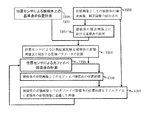
- the tip of the optical fibers 106 and 109 on the morphological image of the subject such as an MRI image during the operation of attaching the optical fiber plug 204 to the holder 108 and bringing the optical fibers 106 and 109 into contact with the subject 107 Display the position in real time. This assists in determining the installation positions of the optical fibers 106 and 109.
- a method of displaying the optical fiber installation position on the morphological image of the subject such as an MRI image in real time during the operation of installing the optical fibers 106 and 109 on the subject 107 is a known method described in Patent Document 1. Since this is a technique, the outline will be described here, and the application of the measurement technique of the present invention in the process will be described below.
- FIG. 23 is a flowchart showing a flow of displaying the optical fiber installation position on the morphological image in real time. Similar to steps 1208 and 1201 of the first embodiment, the position of the reference point on the subject 107 is measured using the movable position sensor 118. However, in Embodiment 1, Steps 1208 and 1201 are performed after all the optical fiber plugs 204 are first attached to the holder 108. However, in Embodiment 3, Steps 1208 and 1201 are performed before attaching the optical fiber plug 204. To measure the reference point.
- a pre-imaged morphological image (a head surface image of a subject imaged by an MRI apparatus, a CT apparatus, or the like, a brain surface image) is read, and a reference The position of the point is obtained, and a conversion parameter for projecting the reference point measured in step 1201 onto the reference point of the morphological image of the subject is obtained.
- the optical fiber plug 204 is attached to the holder 108, and the engaging member 502 is engaged with the attached optical fiber plug 204 in the same manner as in steps 1209 and 1205 of the first embodiment. Measure the tip position of (step 1705). This measurement may be performed every time one optical fiber plug 204 is attached, or several optical fiber plugs 204 may be attached and measured together.
- the projected tip positions of the optical fibers 106 and 109 are projected onto the morphological image using the conversion parameter obtained in step 1204, and the position coordinates are obtained (step 1706).
- the tip positions of the optical fibers 106 and 109 on the morphological image are displayed on the morphological image (step 1707).
- an image 1801 in which the tip positions 1803 of the optical fibers 106 and 109 are superimposed on the morphological image 1402 can be generated and displayed.
- steps 1705 to 1707 the positions of all the optical fibers 106 and 109 can be displayed on the form image 1402.
- the operator can grasp in real time which position the optical fiber installation position is on the morphological image of the subject. Therefore, the image 1801 assists in determining the optical fiber installation position on the subject 107.
- the tip positions of the optical fibers 106 and 109 can be measured by the movable position sensor 118 without removing the optical fiber plug 204 from the holder 108, the positions of the attached optical fibers 106 and 109 can be determined. It can be displayed accurately. Further, since the work of removing the optical fiber plug 204 is not necessary for position measurement, the real-time property of displaying the optical fiber installation point can be further increased.
- the optical fiber 106, 109 on the morphological image of the subject 107 is attached in the same manner as in the third embodiment, the tip position is displayed in real time, and the light when the biological light measurement has been performed in the past is performed. The tip positions of the fibers 106 and 109 are also displayed so that the operator can grasp the positional relationship on the image.
- FIG. 25 is a flowchart showing the process of the present embodiment. Steps 1201 to 1204, 1208, 1705, and 1706 are the same as those in the third embodiment, and thus description thereof is omitted. Through these steps, the position coordinates on the morphological image of the subject at the tip positions of the optical fibers 106 and 109 attached by work are obtained.
- step 1907 the position of the reference point on the subject 107 when measured in the past is read from the storage unit 115, and a conversion parameter for projecting the reference point on the morphological image read in step 1202 is obtained (step 1908). ).
- This process is performed in the same manner as in step 1204.
- the signal processing unit 103 takes in the tip positions of the optical fibers 106 and 109 when measured in the past from the storage unit 115, projects them onto the morphological image using the obtained conversion parameters, and obtains the position coordinates (step 1909, 1909). This processing can be performed in the same manner as in step 1706.
- the tip positions of the past optical fibers 106 and 109 fetched from the storage unit 115 in step 1909 may be only those corresponding to the optical fibers 106 and 109 measured in step 1705, or for all the optical fibers 106 and 109. You may capture it.
- step 1910 The position of the tip end of the currently installed optical fibers 106 and 109 and the position of the past optical fibers 106 and 109 obtained in step 1706 are superimposed on the morphological image (step 1910).
- an image 1801 in which the tip positions 1803 of the currently installed optical fibers 106 and 109 and the tip positions 2004 of the optical fibers 106 and 109 at the time of past measurement are superimposed on the morphological image 1402. Can be generated and displayed. Therefore, the operator confirms whether the installation positions of the optical fibers 106 and 109 when the biological light measurement is performed on the morphological image 1402 of the subject in the past match the positions of the optical fibers 106 and 109 attached in the current operation. The positional relationship can be ascertained. If the positional relationship is deviated, the holder 108 can be displaced and the optical fiber plug 204 can be reattached. Therefore, the biological optical measurement can be performed by bringing the optical fiber into contact with the position corresponding to the optical fiber position in the past measurement.
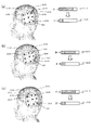
- FIG. 27 In biological light measurement, there are a plurality of optical fibers 106 and 109, both of which are held by the holder 108. Therefore, the optical fibers 106 and 109 cannot be moved completely independently of each other.
- the three optical fiber installation points are matched with the positions of the optical fiber installation points when biological light was measured in the past.
- the head surface image 2101 and the brain surface image 2102 of the subject along with the position A (2104), the position B (2105), the position of the tip of the optical fiber when biological light was measured in the past C (2106) is displayed.
- the position of the holder 108 is not necessarily important and may not be displayed, but here, it is shown in the figure for convenience of explanation.
- the tip position a (2107) of the optical fiber installed first is displayed in real time.
- the position of the holder 108 is corrected so as to match this with the position A (2104).
- the difference between position a (2107) and position A (2104) is It is possible for the signal processing unit 113 to display error bars 2112 and 2113 having a length proportional to Aa
- the length of the error bar 2112 when the deviation is large is long, and the error bar 2113 when the deviation is small is displayed short.
- the operator can easily install the first optical fiber at the position A (2104) by moving the holder 108 so that the error bar becomes shorter.
- the signal processing unit 113 may display an arrow 2114 indicating the direction of the vector Aa corresponding to the operation direction for correcting the deviation direction on the display screen. Further, a beep sound having a volume proportional to the magnitude of the deviation
- Fig. 27 (b) shows how the second optical fiber is installed.
- the position b (2108) of the optical fiber installation point to be installed second is displayed in real time, and the optical fiber is installed so as to match the position B (2105).
- the holder 108 since the first optical fiber plug and the second optical fiber plug are connected by the holder 108, while holding the first optical fiber already installed by hand so as not to move from the position A (2109). Then, the holder 108 is shifted, and installation is performed so that the position b (2108) of the optical fiber installed second coincides with the past position B (2105).
- the magnitude of the deviation between the position b (2108) and the position B (2105) is
- Fig. 27 (c) The position c (2110) of the optical fiber installation point to be installed third is displayed in real time, and the optical fiber is installed so as to match the position C (2106). At this time, since the first and second optical fiber plugs and the third optical fiber plug are connected by the holder, the already installed first and second optical fibers are positioned at position A (2109) and position B, respectively. Install the third optical fiber while holding it with your hand so that it does not move from (2111). Similarly, error bars 2118 and 2119 having a length proportional to
- FIG. 28 shows the current position of the three optical fibers by simultaneously measuring using the three movable position sensors 118, as position a (2207), position b (2208), and position c (2209). It is displayed in real time.
- the coordinate values of the current optical fiber positions a, b, c (2207, 2208, 2209) are respectively a, b, c, and the past optical fiber positions A, B, C (2204, 2205, 2206).
- the coordinate values of A, B, and C are proportional to
- the error bars 2214, 2215, 2216, 2218, 2219 and 2220 of the lengths can be displayed simultaneously.
- arrows 2210, 2211 and 2212 indicating the vectors Aa, Bb and Cc can also be shown.
- ) / 3 are displayed as the average of the deviations of the three optical fiber installation positions.
- the vector 2221 can also be displayed.
- ) / 3 can be generated.
- the position of the real-time optical fiber is superimposed on the morphological image of the subject measured with an MRI apparatus or the like, but in the fifth embodiment, on the pseudo morphological image (wireframe image) of the subject, Real-time optical fiber position is superimposed and displayed.
- FIG. 29 is a flowchart showing the process of the fifth embodiment.
- steps 1201, 1205, 1208, 1209, 1502-1505, and 1507 are the same as those in FIG. 21 of the second embodiment, but the difference from the second embodiment is due to these steps.
- the position coordinates on the morphological image of the subject at the tip positions of the optical fibers 106 and 109 attached by the current operation are obtained. This is the same as in the third and fourth embodiments.
- step 1907 of the fourth embodiment the position of the reference point on the subject 107 when measured in the past is read from the storage unit 115, and this reference point is projected onto the pseudomorphic image read in step 1503.
- a conversion parameter is obtained (step 2309).
- the signal processing unit 103 takes in the tip positions of the optical fibers 106 and 109 when measured in the past from the storage unit 115, and projects them onto the pseudo form image.
- the position coordinates are obtained (steps 2309 to 2311).
- the difference from the fourth embodiment is that, while the projection is performed on the morphological image in the fourth embodiment, the projection is performed on the pseudo morphological image in the fifth embodiment.
- the tip positions of the optical fibers 106 and 109 that are currently attached and the positions of the past optical fibers 106 and 109 obtained in step 1507 are superimposed and displayed on the pseudo form image (step 2312). Thereby, the tip position of the optical fiber currently attached and the tip position of the past optical fiber can be superimposed and displayed in real time on the pseudo form image of the subject.
- FIG. 30 as an example, an image obtained by superimposing the tip position 1803 of the currently attached optical fiber on the pseudo-morphological image 2401 of the subject in real time together with the tip position 2004 of the optical fiber when the biological light measurement was performed in the past. An example is shown.
- both images are highly accurate. It is desirable to overlay accurately.
- the position of the optical fiber of the biological light measurement device is detected by bringing the tip of the movable position sensor into contact with the optical fiber installation hole of the probe holder.
- the size of the optical fiber installation hole of the probe holder is about 1 to 2 cm, and the probe holder is lifted from the scalp by scalp hair. From the position of the optical fiber installation hole of the probe holder, the tip of the optical fiber and the scalp It is not possible to directly measure the contact position. In addition, the size and shape of the subject's head is greatly different from one individual to another, and the distance between the probe holder and the scalp greatly depends on the amount, length, and growth of the hair. For this reason, it is difficult to accurately estimate the position of the tip of the optical fiber from the position of the optical fiber installation hole of the probe holder.
- the task of irradiating the scalp with light from an optical fiber and fixing the tip of the optical fiber to the scalp so that light can be detected from another optical fiber using a biological optical measurement device is applied to the scalp of the optical fiber.
- This is an extremely delicate and persevering work because the contact of the hair is hindered by the hair.
- a sheet-like probe holder is fixed to the head of the subject with a belt or the like, the tip of the optical fiber is brought into contact with the scalp while avoiding the hair with a thin stick, and the optical fiber is probed. Secure to the holder.
- the position of the tip of the optical fiber is measured with a movable position sensor as follows in order to superimpose the image of the biological light measurement device with the X-ray CT image or the like.
- the procedure is as follows. Remove one of the optical fibers fixed with great care as described above from the hole in the probe holder, insert a movable position sensor where the tip of the optical fiber was, In this method, the position is detected by contacting the scalp, and the optical fiber is again fixed to the original position while avoiding the hair with a stick. During this time, it is necessary to carry out so as not to come into contact with adjacent optical fibers or cables. This process is repeated sequentially for all optical fibers (usually 30 to 80).
- the method of measuring the contact position of the scalp of an optical fiber with a movable position sensor requires time to prepare for the measurement, so the number of subjects that can be measured per day is limited to one or two. There is a problem. Since it takes time to attach the optical fiber to the subject, the subject is also burdened. In addition, since the optical fiber is once removed from the probe holder and a movable position sensor is inserted at the position where the tip of the optical fiber was, the contact position of the optical fiber to the scalp can be measured directly. Therefore, the operator will measure the position of the tip before the removal while estimating the position, and accurate position measurement cannot be performed. According to the embodiment of the present invention, these problems can be solved.
Landscapes
- Health & Medical Sciences (AREA)
- Life Sciences & Earth Sciences (AREA)
- Physics & Mathematics (AREA)
- Engineering & Computer Science (AREA)
- Animal Behavior & Ethology (AREA)
- Veterinary Medicine (AREA)
- Biophysics (AREA)
- Pathology (AREA)
- Public Health (AREA)
- Biomedical Technology (AREA)
- Heart & Thoracic Surgery (AREA)
- Medical Informatics (AREA)
- Molecular Biology (AREA)
- Surgery (AREA)
- General Health & Medical Sciences (AREA)
- Neurology (AREA)
- Cardiology (AREA)
- Physiology (AREA)
- Nuclear Medicine, Radiotherapy & Molecular Imaging (AREA)
- Radiology & Medical Imaging (AREA)
- Hematology (AREA)
- Optics & Photonics (AREA)
- Spectroscopy & Molecular Physics (AREA)
- Psychology (AREA)
- Neurosurgery (AREA)
- Human Computer Interaction (AREA)
- Measurement Of The Respiration, Hearing Ability, Form, And Blood Characteristics Of Living Organisms (AREA)
- Investigating Or Analysing Materials By Optical Means (AREA)
- Pulmonology (AREA)
Description
以下、本発明の実施形態についてより具体的に説明する。
(装置構成)
まず、装置の全体構成について図1等を用いて説明する。図1は、生体光計測装置の全体構成のブロック図である。図2は、被検体107に光ファイバ106,109を取り付けた状態を示す斜視図である。
上述したように、光ファイバ106、109の先端部には、光ファイバプラグ204が取り付けられ、光ファイバプラグ204の外周を、ホルダ108の穴の縁のリングに係合させることにより、ホルダ108に着脱可能に固定される。以下、光ファイバプラグ204の構造について、図3を用いて詳しく説明する。図3(a)、(b)および(c)は、それぞれ光ファイバプラグ204の斜視図、断面図および断面の斜視図である。光ファイバ106の光ファイバプラグ204と、光ファイバ109の光ファイバプラグ204は同じ構造であるので、ここでは光ファイバ106の光ファイバプラグ204を例に以下説明する。
図6(a)は、移動型位置センサ118の斜視図と、これに固定される係合部材502の部品の斜視図である。図6(b)、(c)および(d)は、移動型位置センサに係合部材502を固定した状態の側面図、断面図、および、断面の斜視図である。
これにより、光ファイバ106の先端位置(x2 y2 z2)を求めることができる。
次に、図10等を用いて、別途測定しておいたMRI画像等の被検体の形態画像と、生体光計測画像とを重畳した画像を生成する方法を説明する。MRI画像等の形態画像と生体光計測結果との重畳画像の生成プロセスの詳細は、特許文献1等に記載されている広く知られた技術であるので、ここでは、概略を説明し、そのプロセスにおける本発明の光ファイバおよび基準点の位置測定方法について詳しく説明する。
上述してきた本実施形態の位置計測方法によって、32個の光ファイバ106,109の位置の計測を行った際にかかった作業時間を測定した。その結果を図17に示す。図17において縦軸は、操作にかかった作業時間を示し、横軸は5人の操作者を示す。
実施形態1では、被検体の形態画像に生体光計測画像を重畳したが、本発明はこれに限定されるものではない。実施形態2では、被検体の擬似形態画像と生体光計測結果との重畳画像を生成する。
実施形態3では、光ファイバプラグ204をホルダ108に取り付け、被検体107に光ファイバ106,109を当接する作業中に、MRI画像等の被検体の形態画像上での光ファイバ106,109の先端位置をリアルタイムに表示する。これにより、光ファイバ106,109の設置位置の決定を補助する。被検体107への光ファイバ106,109を設置する作業中に、MRI画像等の被検体の形態画像上での光ファイバ設置位置をリアルタイムに表示する方法は、特許文献1に記載された公知の技術であるので、ここでは概略を説明し、そのプロセスにおける本発明の計測手法を適用する箇所について以下説明する。
実施形態4では、実施形態3と同様に被検体107の形態画像上での光ファイバ106,109を取り付けながら、その先端位置をリアルタイムに表示するとともに、過去に生体光計測を行った時の光ファイバ106,109の先端位置も併せて表示し、その位置関係を操作者が画像上で把握できるようにする。
図27(a)に示すように、被検体の頭表画像2101、脳表画像2102と共に、過去に生体光計測した時の光ファイバの先端の位置A(2104)、位置B(2105)、位置C(2106)が表示されている。ホルダ108の位置は必ずしも重要ではなく、表示しない場合もあるが、ここでは説明の都合上、図中に記載する。
実施形態4では、MRI装置等で測定した被検体の形態画像上に、リアルタイムの光ファイバの位置を重畳表示したが、実施形態5では、被検体の疑似形態画像(ワイヤフレーム画像)上に、リアルタイムの光ファイバの位置を重畳表示する。
Claims (15)
- 被検体に光を照射し、被検体を通過した光を計測する光照射・計測部と、前記光照射・計測部の計測データを処理して生体光計測画像を生成する信号処理部と、前記光照射・計測部の被検体への光照射位置および被検体からの通過光の取り出し位置を測定する位置計測部とを有し、
前記光照射・計測部は、複数の光ファイバと、前記複数の光ファイバにそれぞれ取り付けられた複数の光ファイバプラグと、被検体の測定部位に着脱可能に固定され、前記複数の光ファイバプラグを保持するホルダとを備え、
前記位置計測部は、移動型位置センサと、前記移動型位置センサに取り付けられ前記ホルダに保持された前記複数の光ファイバプラグと着脱可能に係合する形状である係合部材とを具備することを特徴とする生体光計測装置。 - 前記係合部材で前記光ファイバプラグと係合した状態の前記移動型位置センサの検出した位置と前記測定部位の表面との位置関係から前記複数の光ファイバプラグの前記複数の光ファイバの先端位置を演算する演算部を備えることを特徴とする請求項1に記載の生体光計測装置。
- 請求項1に記載の生体光計測装置において、前記複数の光ファイバプラグは、前記複数の光ファイバに固定された固定部を含み、
前記係合部材は、前記光ファイバプラグと係合した際に、前記移動型位置センサの先端が前記固定部の端部と接触する構造であることを特徴とする生体光計測装置。 - 請求項3に記載の生体光計測装置において、前記固定部は、前記複数の光ファイバにそれぞれ固定された複数の筒状部と、前記複数の筒状部の端部にそれぞれ固定された複数の棒状部とを備え、
前記移動型位置センサは、前記複数の棒状部の端部の各々に接触させ、それぞれの位置を検出することを特徴とする生体光計測装置。 - 請求項1に記載の生体光計測装置において、前記係合部材は、前記複数の光ファイバプラグの外周と係合する形状の開口を備えることを特徴とする生体光計測装置。
- 請求項2に記載の生体光計測装置において、前記係合部材は、前記複数の光ファイバプラグの外周と係合する形状の開口を備え、
前記係合部材の前記開口は、深さ方向が前記移動型位置センサの軸方向と同軸に形成され、前記開口に挿入された前記複数の光ファイバプラグの前記複数の光ファイバを、前記移動型位置センサの軸方向と同軸に保持し、
前記演算部は、前記移動型位置センサの先端から前記軸方向に、前記位置関係により定まる距離だけ離れた位置を、前記複数の光ファイバのそれぞれの先端位置として演算により求めることを特徴とする生体光計測装置。 - 請求項5に記載の生体光計測装置において、前記複数の光ファイバは、先端部の外周が前記複数の光ファイバプラグの固定部にそれぞれ固定され、前記複数の光ファイバプラグの内部で屈曲して前記複数の光ファイバプラグの側面から外部にそれぞれ引き出され、
前記係合部材の前記開口の縁には、前記光ファイバプラグの側面から引き出された光ファイバが挿入される切り欠きが備えられていることを特徴とする生体光計測装置。 - 請求項1に記載の生体光計測装置において、前記複数の光ファイバプラグは、前記固定部を前記光ファイバの先端部の軸方向に対して移動可能にそれぞれ保持する保持部を含み、
前記ホルダは、前記複数の光ファイバプラグをそれぞれ保持するための複数の穴を備え、
前記複数の光ファイバプラグの前記保持部の外周は、前記ホルダの前記複数の穴の周縁にそれぞれ係合する形状であることを特徴とする生体光計測装置。 - 請求項1に記載の生体光計測装置において、前記位置計測部は、前記光ファイバプラグが配置されていない被検体の基準部位を測定する際に、前記係合部材と装着する疑似プラグをさらに有することを特徴とする生体光計測装置。
- 請求項9に記載の生体光計測装置において、
前記信号処理部は、
前記疑似プラグを前記係合部材に装着して、前記被検体の基準部位を測定するように操作者に促す所定の表示を表示装置に表示させ、前記位置計測部が計測した前記被検体の基準部位の位置データを前記位置計測部から取り込み、
前記疑似プラグを前記係合部材から取り外して、前記複数の光ファイバの先端位置を測定するように操作者に促す所定の表示を前記表示装置に表示させ、前記位置計測部が計測した前記複数の光ファイバの先端の位置データを前記位置計測部からそれぞれ取り込み、 取り込んだ基準位置および前記複数の光ファイバの先端の位置情報を生体光計測画像に付加することを特徴とする生体光計測装置。 - 請求項10に記載の生体光計測装置において、前記信号処理部は、前記位置情報を用いて前記生体光計測画像を、前記被検体の形態を表す画像に重畳した画像を生成することを特徴とする生体光計測装置。
- 被検体に光を照射し、被検体を通過した光を計測する生体光計測方法であって、
複数の光ファイバプラグが先端部にそれぞれ取り付けられた複数の光ファイバの先端を、前記複数の光ファイバプラグを保持するホルダによって、前記被検体に当接するように配置する光ファイバ取り付け工程と、
前記複数の光ファイバプラグと係合可能な係合部材がそれぞれ取り付けられた移動型位置センサを、複数の前記光ファイバプラグと前記係合部材によって順次係合させ、その時の前記移動型位置センサの検出位置と測定部位の表面との位置関係から、複数の前記光ファイバの先端位置を演算により求める光ファイバ位置検出工程とを有することを特徴とする生体光計測方法。 - 請求項12に記載の生体光計測方法において、前記係合部材に疑似プラグを装着し、前記疑似プラグの先端を、前記光ファイバプラグが配置されていない被検体の基準部位に接触させて、その時の前記移動型位置センサの検出位置と測定部位の表面との位置関係から、基準位置を演算により求める基準位置検出工程をさらに有することを特徴とする生体光計測方法。
- 請求項13に記載の生体光計測方法において、前記基準位置検出工程の前に、前記係合部材に前記疑似プラグを装着するように操作者に促す表示を表示装置に表示する疑似プラグ装着表示工程をさらに有することを特徴とする生体光計測方法。
- 生体光計測装置の移動型位置センサに取り付ける係合部材であって、
前記生体光計測装置の光ファイバに取り付けられた光ファイバプラグと、所定の位置関係で着脱可能に係合する形状を成していることを特徴とする移動型位置センサ用係合部材。
Priority Applications (4)
| Application Number | Priority Date | Filing Date | Title |
|---|---|---|---|
| JP2014507887A JP5943362B2 (ja) | 2012-03-29 | 2013-03-26 | 生体光計測装置、生体光計測方法および移動型位置センサ用係合部材 |
| US14/382,514 US9883825B2 (en) | 2012-03-29 | 2013-03-26 | Living body optical measurement apparatus, living body optical measurement method, and engagement member for mobile position sensor |
| CN201380011660.3A CN104159523B (zh) | 2012-03-29 | 2013-03-26 | 生物体光测量装置、生物体光测量方法以及移动型位置传感器用卡合部件 |
| EP13767849.6A EP2832304A4 (en) | 2012-03-29 | 2013-03-26 | DEVICE FOR MEASURING BIOLOGICAL LIGHT, METHOD FOR MEASURING BIOLOGICAL LIGHT, AND LOCKING ELEMENT FOR A MOBILE POSITION SENSOR |
Applications Claiming Priority (2)
| Application Number | Priority Date | Filing Date | Title |
|---|---|---|---|
| JP2012077278 | 2012-03-29 | ||
| JP2012-077278 | 2012-03-29 |
Publications (1)
| Publication Number | Publication Date |
|---|---|
| WO2013146725A1 true WO2013146725A1 (ja) | 2013-10-03 |
Family
ID=49259976
Family Applications (1)
| Application Number | Title | Priority Date | Filing Date |
|---|---|---|---|
| PCT/JP2013/058673 Ceased WO2013146725A1 (ja) | 2012-03-29 | 2013-03-26 | 生体光計測装置、生体光計測方法および移動型位置センサ用係合部材 |
Country Status (5)
| Country | Link |
|---|---|
| US (1) | US9883825B2 (ja) |
| EP (1) | EP2832304A4 (ja) |
| JP (1) | JP5943362B2 (ja) |
| CN (1) | CN104159523B (ja) |
| WO (1) | WO2013146725A1 (ja) |
Cited By (1)
| Publication number | Priority date | Publication date | Assignee | Title |
|---|---|---|---|---|
| WO2022145176A1 (ja) * | 2020-12-28 | 2022-07-07 | 国立研究開発法人産業技術総合研究所 | 脳機能計測装置及び脳機能計測方法 |
Families Citing this family (40)
| Publication number | Priority date | Publication date | Assignee | Title |
|---|---|---|---|---|
| KR102249824B1 (ko) * | 2014-02-24 | 2021-05-10 | 삼성전자주식회사 | 신체 정보 감지장치 및 이의 신체 정보 감지방법 |
| US10791981B2 (en) * | 2016-06-06 | 2020-10-06 | S Square Detect Medical Devices | Neuro attack prevention system, method, and apparatus |
| WO2020236371A1 (en) | 2019-05-21 | 2020-11-26 | Hi Llc | Photodetector architectures for efficient fast-gating |
| CA3137921A1 (en) | 2019-06-06 | 2020-12-10 | Hi Llc | Photodetector systems with low-power time-to-digital converter architectures |
| US20210259620A1 (en) * | 2020-02-21 | 2021-08-26 | Hi Llc | Integrated light source assembly with laser coupling for a wearable optical measurement system |
| US11771362B2 (en) * | 2020-02-21 | 2023-10-03 | Hi Llc | Integrated detector assemblies for a wearable module of an optical measurement system |
| WO2021167890A1 (en) | 2020-02-21 | 2021-08-26 | Hi Llc | Wearable module assemblies for an optical measurement system |
| US11883181B2 (en) | 2020-02-21 | 2024-01-30 | Hi Llc | Multimodal wearable measurement systems and methods |
| US11630310B2 (en) | 2020-02-21 | 2023-04-18 | Hi Llc | Wearable devices and wearable assemblies with adjustable positioning for use in an optical measurement system |
| US11969259B2 (en) | 2020-02-21 | 2024-04-30 | Hi Llc | Detector assemblies for a wearable module of an optical measurement system and including spring-loaded light-receiving members |
| US11950879B2 (en) | 2020-02-21 | 2024-04-09 | Hi Llc | Estimation of source-detector separation in an optical measurement system |
| US12029558B2 (en) | 2020-02-21 | 2024-07-09 | Hi Llc | Time domain-based optical measurement systems and methods configured to measure absolute properties of tissue |
| US12144653B2 (en) | 2020-02-21 | 2024-11-19 | Hi Llc | Systems, circuits, and methods for reducing common-mode noise in biopotential recordings |
| US11187575B2 (en) | 2020-03-20 | 2021-11-30 | Hi Llc | High density optical measurement systems with minimal number of light sources |
| US11903676B2 (en) | 2020-03-20 | 2024-02-20 | Hi Llc | Photodetector calibration of an optical measurement system |
| US11857348B2 (en) | 2020-03-20 | 2024-01-02 | Hi Llc | Techniques for determining a timing uncertainty of a component of an optical measurement system |
| US11645483B2 (en) | 2020-03-20 | 2023-05-09 | Hi Llc | Phase lock loop circuit based adjustment of a measurement time window in an optical measurement system |
| US11819311B2 (en) | 2020-03-20 | 2023-11-21 | Hi Llc | Maintaining consistent photodetector sensitivity in an optical measurement system |
| US11864867B2 (en) | 2020-03-20 | 2024-01-09 | Hi Llc | Control circuit for a light source in an optical measurement system by applying voltage with a first polarity to start an emission of a light pulse and applying voltage with a second polarity to stop the emission of the light pulse |
| US12138068B2 (en) | 2020-03-20 | 2024-11-12 | Hi Llc | Techniques for characterizing a nonlinearity of a time-to-digital converter in an optical measurement system |
| US11245404B2 (en) | 2020-03-20 | 2022-02-08 | Hi Llc | Phase lock loop circuit based signal generation in an optical measurement system |
| US12059262B2 (en) | 2020-03-20 | 2024-08-13 | Hi Llc | Maintaining consistent photodetector sensitivity in an optical measurement system |
| US11877825B2 (en) | 2020-03-20 | 2024-01-23 | Hi Llc | Device enumeration in an optical measurement system |
| WO2021188487A1 (en) | 2020-03-20 | 2021-09-23 | Hi Llc | Temporal resolution control for temporal point spread function generation in an optical measurement system |
| WO2021188488A1 (en) | 2020-03-20 | 2021-09-23 | Hi Llc | Bias voltage generation in an optical measurement system |
| US11941857B2 (en) | 2020-05-26 | 2024-03-26 | Hi Llc | Systems and methods for data representation in an optical measurement system |
| US12436280B2 (en) | 2020-08-11 | 2025-10-07 | Hi Llc | Maintaining consistent photodetector sensitivity in an optical measurement system |
| CN112057057B (zh) * | 2020-08-11 | 2022-04-26 | 上海掌门科技有限公司 | 调整脉搏测量装置、测量脉搏信号的方法与设备 |
| US11789533B2 (en) | 2020-09-22 | 2023-10-17 | Hi Llc | Synchronization between brain interface system and extended reality system |
| WO2022150155A1 (en) | 2021-01-06 | 2022-07-14 | Hi Llc | Devices, systems, and methods using wearable time domain-based activity tracker |
| US12433517B2 (en) | 2021-02-19 | 2025-10-07 | Hi Llc | Devices, systems, and methods for calibrating an optical measurement device |
| WO2022182528A1 (en) | 2021-02-26 | 2022-09-01 | Hi Llc | Systems and methods for calibration of an optical measurement system |
| US11612808B2 (en) | 2021-02-26 | 2023-03-28 | Hi Llc | Brain activity tracking during electronic gaming |
| US11543885B2 (en) | 2021-05-26 | 2023-01-03 | Hi Llc | Graphical emotion symbol determination based on brain measurement data for use during an electronic messaging session |
| US12235154B2 (en) | 2021-06-15 | 2025-02-25 | Hi Llc | Maintaining consistent photodetector sensitivity in an optical measurement system |
| US12078531B2 (en) | 2021-07-28 | 2024-09-03 | Hi Llc | Devices, systems, and methods for calibrating an optical measurement device |
| GB202204719D0 (en) | 2022-03-31 | 2022-05-18 | Gowerlabs Ltd | Light guide module and apparatus for measuring changes in chromophore concentration |
| US12502079B2 (en) | 2022-11-17 | 2025-12-23 | Hi Llc | Instrument response function monitor on an optical measurement device |
| CN118452835B (zh) * | 2024-06-05 | 2025-03-21 | 慧创科仪(北京)科技有限公司 | 一种用于近红外脑功能成像设备的探头固定装置 |
| CN118766433A (zh) * | 2024-07-30 | 2024-10-15 | 丹阳慧创医疗设备有限公司 | 一种近红外探头组件以及近红外头帽组件 |
Citations (6)
| Publication number | Priority date | Publication date | Assignee | Title |
|---|---|---|---|---|
| JP2004357899A (ja) * | 2003-06-04 | 2004-12-24 | Hitachi Medical Corp | 計測装置 |
| US7190826B2 (en) * | 2003-09-16 | 2007-03-13 | Electrical Geodesics, Inc. | Measuring the location of objects arranged on a surface, using multi-camera photogrammetry |
| JP4266453B2 (ja) | 1999-09-14 | 2009-05-20 | 株式会社日立メディコ | 生体光計測装置 |
| JP2011046072A (ja) | 2009-08-26 | 2011-03-10 | Yokohama Rubber Co Ltd:The | タイヤ加硫用モールドの製造方法およびタイヤ加硫用モールド |
| JP2011050504A (ja) * | 2009-08-31 | 2011-03-17 | Topcon Corp | 測定装置、測定方法、およびプログラム |
| WO2011046072A1 (ja) * | 2009-10-14 | 2011-04-21 | 株式会社 日立メディコ | 生体光計測装置及び参照画像表示方法 |
Family Cites Families (7)
| Publication number | Priority date | Publication date | Assignee | Title |
|---|---|---|---|---|
| JP3579686B2 (ja) * | 1995-08-07 | 2004-10-20 | アークレイ株式会社 | 測定位置再現方法および測定位置再現装置並びにそれを使用した光学測定装置 |
| JP3839202B2 (ja) | 1999-10-28 | 2006-11-01 | 株式会社日立製作所 | 生体光計測装置及びこの装置を機能させるためのプログラム |
| JP2002355246A (ja) * | 2001-05-30 | 2002-12-10 | Hitachi Medical Corp | 生体光計測用装着具および生体光計測装置 |
| JP2003088528A (ja) * | 2001-09-18 | 2003-03-25 | Hitachi Medical Corp | 生体光計測装置 |
| JP2006122086A (ja) * | 2004-10-26 | 2006-05-18 | Hitachi Ltd | 生体光計測装置 |
| JP4968167B2 (ja) * | 2008-04-24 | 2012-07-04 | 株式会社島津製作所 | 光生体測定装置及びそれに用いられるホルダ配置支援システム |
| WO2009134674A1 (en) | 2008-04-28 | 2009-11-05 | The Trustees Of Dartmouth College | System, optode and cap for near-infrared diffuse-optical functional neuroimaging |
-
2013
- 2013-03-26 EP EP13767849.6A patent/EP2832304A4/en not_active Withdrawn
- 2013-03-26 WO PCT/JP2013/058673 patent/WO2013146725A1/ja not_active Ceased
- 2013-03-26 US US14/382,514 patent/US9883825B2/en active Active
- 2013-03-26 JP JP2014507887A patent/JP5943362B2/ja active Active
- 2013-03-26 CN CN201380011660.3A patent/CN104159523B/zh not_active Expired - Fee Related
Patent Citations (6)
| Publication number | Priority date | Publication date | Assignee | Title |
|---|---|---|---|---|
| JP4266453B2 (ja) | 1999-09-14 | 2009-05-20 | 株式会社日立メディコ | 生体光計測装置 |
| JP2004357899A (ja) * | 2003-06-04 | 2004-12-24 | Hitachi Medical Corp | 計測装置 |
| US7190826B2 (en) * | 2003-09-16 | 2007-03-13 | Electrical Geodesics, Inc. | Measuring the location of objects arranged on a surface, using multi-camera photogrammetry |
| JP2011046072A (ja) | 2009-08-26 | 2011-03-10 | Yokohama Rubber Co Ltd:The | タイヤ加硫用モールドの製造方法およびタイヤ加硫用モールド |
| JP2011050504A (ja) * | 2009-08-31 | 2011-03-17 | Topcon Corp | 測定装置、測定方法、およびプログラム |
| WO2011046072A1 (ja) * | 2009-10-14 | 2011-04-21 | 株式会社 日立メディコ | 生体光計測装置及び参照画像表示方法 |
Non-Patent Citations (1)
| Title |
|---|
| See also references of EP2832304A4 * |
Cited By (3)
| Publication number | Priority date | Publication date | Assignee | Title |
|---|---|---|---|---|
| WO2022145176A1 (ja) * | 2020-12-28 | 2022-07-07 | 国立研究開発法人産業技術総合研究所 | 脳機能計測装置及び脳機能計測方法 |
| JPWO2022145176A1 (ja) * | 2020-12-28 | 2022-07-07 | ||
| JP7503338B2 (ja) | 2020-12-28 | 2024-06-20 | 国立研究開発法人産業技術総合研究所 | 脳機能計測装置及び脳機能計測方法 |
Also Published As
| Publication number | Publication date |
|---|---|
| CN104159523A (zh) | 2014-11-19 |
| US20150038811A1 (en) | 2015-02-05 |
| US9883825B2 (en) | 2018-02-06 |
| JPWO2013146725A1 (ja) | 2015-12-14 |
| CN104159523B (zh) | 2016-02-17 |
| JP5943362B2 (ja) | 2016-07-05 |
| EP2832304A1 (en) | 2015-02-04 |
| EP2832304A4 (en) | 2015-11-11 |
Similar Documents
| Publication | Publication Date | Title |
|---|---|---|
| JP5943362B2 (ja) | 生体光計測装置、生体光計測方法および移動型位置センサ用係合部材 | |
| EP1360927B1 (en) | Optical imaging device and optical imaging detecting method | |
| JP5324999B2 (ja) | 生体光計測装置及び生体光計測方法 | |
| JP4097522B2 (ja) | 生体光計測装置 | |
| JP2021101900A (ja) | 学習データ作成装置、方法及びプログラム並びに医療画像認識装置 | |
| JP5347448B2 (ja) | 生体測定装置 | |
| EP2489305B1 (en) | Biophotometer | |
| JP2013236758A (ja) | 情報処理装置、情報処理方法、プログラム及び情報処理システム | |
| JP5686739B2 (ja) | 磁気式位置検出部を備えた検査装置、磁場計測用冶具、磁場検出用プログラム | |
| JP2003144437A (ja) | 生体光計測装置 | |
| JP2010104586A (ja) | 生体光計測装置及び計測ノイズの推定方法 | |
| JP4411208B2 (ja) | 生体光計測装置 | |
| CN103200858B (zh) | 光学测定装置 | |
| JP2012010776A (ja) | 断層画像処理装置及び方法、並びに光干渉断層画像診断装置 | |
| JP2017038878A (ja) | 生体光計測装置 | |
| US20050261578A1 (en) | Living body measurement system by light, image display methodology and program | |
| EP2201889A1 (en) | Optical apparatus for acquiring structure information and its processing method of optical interference signal | |
| JP5853777B2 (ja) | 光生体計測装置 | |
| KR20150059953A (ko) | 두피 표면 및 단층 영상의 동시구현이 가능한 두피 진단 방법 및 진단 장치 | |
| JP5484786B2 (ja) | 生体光計測装置 | |
| US20140330109A1 (en) | Photobiomedical measurement apparatus | |
| JP5347312B2 (ja) | 光測定装置 | |
| JP2015223277A (ja) | 内視鏡用生体情報センサ |
Legal Events
| Date | Code | Title | Description |
|---|---|---|---|
| WWE | Wipo information: entry into national phase |
Ref document number: 201380011660.3 Country of ref document: CN |
|
| 121 | Ep: the epo has been informed by wipo that ep was designated in this application |
Ref document number: 13767849 Country of ref document: EP Kind code of ref document: A1 |
|
| ENP | Entry into the national phase |
Ref document number: 2014507887 Country of ref document: JP Kind code of ref document: A |
|
| WWE | Wipo information: entry into national phase |
Ref document number: 14382514 Country of ref document: US |
|
| WWE | Wipo information: entry into national phase |
Ref document number: 2013767849 Country of ref document: EP |
|
| NENP | Non-entry into the national phase |
Ref country code: DE |