WO2013147193A1 - ネットワークアプライアンス冗長化システム、制御装置、ネットワークアプライアンス冗長化方法及びプログラム - Google Patents
ネットワークアプライアンス冗長化システム、制御装置、ネットワークアプライアンス冗長化方法及びプログラム Download PDFInfo
- Publication number
- WO2013147193A1 WO2013147193A1 PCT/JP2013/059605 JP2013059605W WO2013147193A1 WO 2013147193 A1 WO2013147193 A1 WO 2013147193A1 JP 2013059605 W JP2013059605 W JP 2013059605W WO 2013147193 A1 WO2013147193 A1 WO 2013147193A1
- Authority
- WO
- WIPO (PCT)
- Prior art keywords
- switch
- header
- packet
- network appliance
- control device
- Prior art date
- Legal status (The legal status is an assumption and is not a legal conclusion. Google has not performed a legal analysis and makes no representation as to the accuracy of the status listed.)
- Ceased
Links
Images


Classifications
-
- H—ELECTRICITY
- H04—ELECTRIC COMMUNICATION TECHNIQUE
- H04L—TRANSMISSION OF DIGITAL INFORMATION, e.g. TELEGRAPHIC COMMUNICATION
- H04L45/00—Routing or path finding of packets in data switching networks
- H04L45/74—Address processing for routing
-
- H—ELECTRICITY
- H04—ELECTRIC COMMUNICATION TECHNIQUE
- H04L—TRANSMISSION OF DIGITAL INFORMATION, e.g. TELEGRAPHIC COMMUNICATION
- H04L12/00—Data switching networks
- H04L12/28—Data switching networks characterised by path configuration, e.g. LAN [Local Area Networks] or WAN [Wide Area Networks]
- H04L12/40—Bus networks
- H04L12/403—Bus networks with centralised control, e.g. polling
-
- H—ELECTRICITY
- H04—ELECTRIC COMMUNICATION TECHNIQUE
- H04L—TRANSMISSION OF DIGITAL INFORMATION, e.g. TELEGRAPHIC COMMUNICATION
- H04L12/00—Data switching networks
- H04L12/28—Data switching networks characterised by path configuration, e.g. LAN [Local Area Networks] or WAN [Wide Area Networks]
- H04L12/46—Interconnection of networks
- H04L12/4641—Virtual LANs, VLANs, e.g. virtual private networks [VPN]
-
- H—ELECTRICITY
- H04—ELECTRIC COMMUNICATION TECHNIQUE
- H04L—TRANSMISSION OF DIGITAL INFORMATION, e.g. TELEGRAPHIC COMMUNICATION
- H04L47/00—Traffic control in data switching networks
- H04L47/10—Flow control; Congestion control
- H04L47/12—Avoiding congestion; Recovering from congestion
- H04L47/125—Avoiding congestion; Recovering from congestion by balancing the load, e.g. traffic engineering
-
- H—ELECTRICITY
- H04—ELECTRIC COMMUNICATION TECHNIQUE
- H04L—TRANSMISSION OF DIGITAL INFORMATION, e.g. TELEGRAPHIC COMMUNICATION
- H04L49/00—Packet switching elements
- H04L49/30—Peripheral units, e.g. input or output ports
-
- H—ELECTRICITY
- H04—ELECTRIC COMMUNICATION TECHNIQUE
- H04L—TRANSMISSION OF DIGITAL INFORMATION, e.g. TELEGRAPHIC COMMUNICATION
- H04L49/00—Packet switching elements
- H04L49/55—Prevention, detection or correction of errors
- H04L49/552—Prevention, detection or correction of errors by ensuring the integrity of packets received through redundant connections
-
- H—ELECTRICITY
- H04—ELECTRIC COMMUNICATION TECHNIQUE
- H04L—TRANSMISSION OF DIGITAL INFORMATION, e.g. TELEGRAPHIC COMMUNICATION
- H04L69/00—Network arrangements, protocols or services independent of the application payload and not provided for in the other groups of this subclass
- H04L69/40—Network arrangements, protocols or services independent of the application payload and not provided for in the other groups of this subclass for recovering from a failure of a protocol instance or entity, e.g. service redundancy protocols, protocol state redundancy or protocol service redirection
-
- H—ELECTRICITY
- H04—ELECTRIC COMMUNICATION TECHNIQUE
- H04L—TRANSMISSION OF DIGITAL INFORMATION, e.g. TELEGRAPHIC COMMUNICATION
- H04L45/00—Routing or path finding of packets in data switching networks
- H04L45/28—Routing or path finding of packets in data switching networks using route fault recovery
-
- H—ELECTRICITY
- H04—ELECTRIC COMMUNICATION TECHNIQUE
- H04L—TRANSMISSION OF DIGITAL INFORMATION, e.g. TELEGRAPHIC COMMUNICATION
- H04L45/00—Routing or path finding of packets in data switching networks
- H04L45/72—Routing based on the source address
-
- H—ELECTRICITY
- H04—ELECTRIC COMMUNICATION TECHNIQUE
- H04L—TRANSMISSION OF DIGITAL INFORMATION, e.g. TELEGRAPHIC COMMUNICATION
- H04L61/00—Network arrangements, protocols or services for addressing or naming
- H04L61/09—Mapping addresses
- H04L61/10—Mapping addresses of different types
- H04L61/103—Mapping addresses of different types across network layers, e.g. resolution of network layer into physical layer addresses or address resolution protocol [ARP]
Definitions
- the present invention is based on the priority claim of Japanese patent application: Japanese Patent Application No. 2012-079953 (filed on March 30, 2012), the entire description of which is incorporated herein by reference. Shall.
- the present invention relates to a network appliance redundancy system, a control device, a network appliance redundancy method, and a program, and in particular, a network appliance redundancy system, a control device, and a network appliance redundancy method in which two different types of network appliances are arranged. And the program.
- Patent Document 1 discloses a configuration in which a master router and a backup router are arranged in parallel. According to the publication, a packet is duplicated at the shared hub in front of the routers arranged in parallel, sent to both the master router and the backup router, the master router forwards the packet, and the backup router discards the packet. It is described that the state can be synchronized without performing communication between the master router and the backup router.
- Patent Document 2 a packet is duplicated in the apparatus, transferred to both the active and standby path control modules to execute the path control process, and from the reception of the internal control packet from the standby system module, A packet transfer apparatus having a mechanism for determining a module state is disclosed.
- Non-Patent Document 1 proposes a method in which the overhead of state exchange can be reduced by duplicating packets to make the state redundant.
- Non-Patent Documents 2 and 3 are documents related to a centralized control type network called OpenFlow.
- JP 2007-208502 A JP-A-2005-303501
- packet headers such as NAT (Network Address Translation), NAPT (Network Address Port Translation), and LB (Load Balancer) (hereinafter referred to as “header conversion”).
- appliance appliance switching
- SBY standby system
- the failover is such that those sessions can continue.
- post-conversion headers the conversion results of the headers (hereinafter referred to as “post-conversion headers”) performed by these appliances differ from device to device, so it is necessary to exchange and share conversion information between ACT and SBY. This is because the sharing method differs for each manufacturer or device. As a result, this restriction impairs the flexibility of network configuration and physical resource allocation.
- Patent Documents 1 and 2 and Non-Patent Document 1 each require modification of the router, and there is a problem that what is sold by each vendor cannot be used as it is.
- An object of the present invention is to provide a network appliance redundancy system, a control device, a network appliance redundancy method, and a program that can contribute to realizing a stateful failover using two different types of network appliances.
- the first switch arranged in the front stage of the two different types of network appliances operated by switching between the active system and the standby system, and the latter stage of the two different types of network appliances.
- a second switch to be arranged; header information of a packet transmitted from the first switch; and header information of a packet received by the second switch via the active network appliance.
- a conversion rule management unit that learns a header conversion rule by the active network appliance, and when switching to the backup network appliance, based on the header conversion rule, the second switch Output packets similar to those of the current network appliance Yo and a control device which instructs the header rewriting, a network appliance redundant system including provided.
- the first switch arranged in the front stage of the two different types of network appliances operated by switching between the active system and the standby system, and the rear stage of the two different types of network appliances. And a header of a packet received by the second switch via the working network appliance and connected to the second switch arranged and transmitted from the first switch. And a conversion rule management unit that learns a header conversion rule by the active network appliance based on the information, and when switching to the backup network appliance, the second The same output as the current network appliance Control device is provided for indicating a header rewriting to the socket.
- the first switch disposed in the front stage of the two different types of network appliances operated by switching between the active system and the standby system, and the second stage of the network appliances of the two different models.
- the second switch to be arranged and the connected control device receive the header information of the packet transmitted from the first switch and the second switch via the working network appliance. Learning the header conversion rule by the active network appliance based on the header information of the packet, and when switching from the active network appliance to the standby network appliance, the header conversion rule Based on the first switch with respect to the second switch.
- a control unit and a step of instructing the same header rewriting and pitch, network appliances redundancy method comprising is provided. The method is tied to a specific machine, the control device that controls the switch.
- the first switch disposed in the front stage of the two different types of network appliances operated by switching between the active system and the standby system, and the second stage of the network appliances of the two different models.
- a second switch arranged, and a computer mounted on a connected control device, the header information of the packet transmitted from the first switch, and the second network via the working network appliance.
- the process of learning the header conversion rule by the active network appliance, and when switching from the active network appliance to the standby network appliance Based on the header conversion rule, the second switch.
- Program for executing the processing for instructing the same header rewriting said first switch is provided to.
- This program can be recorded on a computer-readable (non-transient) storage medium. That is, the present invention can be embodied as a computer program product.
- a redundant configuration using two different types of network appliances can contribute to the realization of stateful failover.
- FIG. 2 It is a figure which shows the structure of one Embodiment of this invention. It is a figure which shows the structure of the network appliance redundancy system of the 1st Embodiment of this invention.
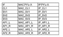
- 3 is a correspondence table between MAC addresses and IP addresses of the respective devices in FIG. 2. It is an example of the redundant structure management table hold
- FIG. 6 is a sequence diagram showing a series of operations (from ARP to ARP response of CL1) of the first exemplary embodiment of the present invention.
- FIG. 5 is a sequence diagram illustrating a series of operations (from CL1 packet transmission to SV1 arrival) according to the first exemplary embodiment of the present invention.
- FIG. 5 is a sequence diagram illustrating a series of operations (from SV1 ARP to ARP response) according to the first exemplary embodiment of the present invention.
- FIG. 5 is a sequence diagram illustrating a series of operations (from SV1 packet transmission to CL1 arrival) according to the first exemplary embodiment of the present invention.
- It is a flowchart showing the operation
- the first switch 30 is arranged in front of two different types of network appliances 20 and 21 that are operated by switching between the active system and the standby system. And a second switch 31 arranged at the subsequent stage of the two different types of network appliances 20 and 21, and a control device 40 for controlling the first and second switches 30 and 31. it can.
- control device 40 includes the header information of the packet transmitted from the first switch 30 and the header information of the packet received by the second switch 31 via the active network appliance. And a conversion rule management unit that learns a header conversion rule by the active network appliance 20. Then, when the control device 40 is switched from the active system to the standby network appliance 21, an output packet similar to that of the active network appliance 20 is sent to the second switch 31 based on the header conversion rule. The header rewrite is instructed so that
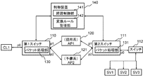
- FIG. 2 is a diagram showing a configuration of the network appliance redundancy system according to the first embodiment of this invention.
- appliances (AP) 120 and 121 arranged in parallel, a first switch 110 arranged in front of these APs 120 and 121, and a second switch 111 arranged in the subsequent stage of these APs 120 and 121.
- a control device 140 that controls the first and second switches 110 and 111 are shown.
- the client CL1 is connected to the port p0 of the first switch 110.
- An appliance (AP) 120 operating in the active system in the initial state is connected to the port p1 of the first switch 110, and an appliance (AP) 121 operating in the standby system in the initial state is connected to the port p2. .
- the appliance (AP1) 120 operating in the active system in the initial state is connected to the port p1 of the second switch 111, and the appliance (AP2) 121 operating in the standby system in the initial state is connected to the port p2.
- the servers SV1 to SV3 are connected to the port p0 of the second switch 111 via the switch 112.
- the appliances (AP) 120 and 121 each have a NAT table (corresponding to an address conversion table) inside.
- the control device 140 has a function of learning a relationship between a MAC (Media Access Control) address and a port and a function of learning a relationship between an IP (Internet Protocol) address and a MAC address as shown in FIG.
- a path control unit 141 having a function of setting a flow entry (control information) and a conversion rule management unit 142.
- the conversion rule management unit 142 of the control device 140 includes a redundant configuration management table for managing the configuration and state of the redundant appliances, and header conversion contents that each system that forms the redundant configuration performs in units of flows. It holds a header conversion table for management.
- the conversion rule management unit 142 of the control device 140 refers to the header conversion table when the active appliance 121 is switched to the standby appliance 121 and refers to the second switch 111 arranged at the subsequent stage of these appliances. The header rewriting is instructed so that the output packet is the same as that of the system appliance 120.
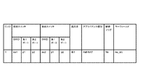
- FIG. 4 is an example of a redundant configuration management table held in the conversion rule management unit 142.
- the appliance and switch connection information (sw1 is the first information) that is set in the redundant configuration in association with the cluster ID (hereinafter referred to as “CLID”) for identifying the appliance having the redundant configuration.
- CLID cluster ID
- the switch ID, sw2 indicates the ID of the second switch.
- the information of the system operating as the active system, the type information of the appliance, and the header before conversion after the header conversion rules for both ACT and SBY are prepared.
- the continuation flag indicating whether to continue the process to be assigned and the header before conversion, it is possible to store a key field for managing a field to be a key necessary for regarding a certain packet sequence as the same flow.
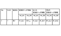
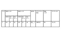
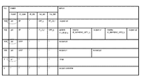
- FIG. 5 is an example of a header conversion table held in the conversion rule management unit 142.
- the header information before conversion that is, the header information of the packet transmitted from the first switch 110 obtained via the second switch 111) in association with the CLID, and the appliances 120 and 121
- Each converted header information after conversion that is, header information of a packet received by the second switch 111) can be stored.
- dl_type indicates a higher layer protocol type
- dl_src indicates a source MAC address
- dl_dst indicates a destination MAC address
- Nw_src indicates a transmission source IP address
- nw_dst indicates a transmission destination IP address.
- tp_src indicates a transmission source L4 port number
- tp_dst indicates a transmission destination L4 port number.
- the first and second switches 110 and 111 include packet processing units 130 and 131 that operate according to the flow entry (control information) set from the path control unit 141 of the control device 140 described above.
- the first and second switches 110 and 111 each include a control information storage unit (not shown) that stores a flow entry (control information).
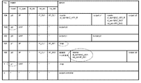
- FIG. 6 is an example of a flow entry (control information) set in the first switch 110.
- the flow entry (the value of the No. field is larger) stored in the upper level is handled as a flow entry with a higher priority.
- the flow entry (control information) is configured in association with a match condition (match) for identifying a flow and an action (action) to be performed on the flow.
- the flow entry 103 receives an IP packet from port p1, that is, from the appliance 120, the source IP address is VIP_L (virtual IP address on the input side of the appliance) and the destination IP address is IP_CL1 (IP address of the client CL1). This indicates that the data should be transferred to the port p0, that is, the client CL1.
- “*” in FIG. 6 indicates a wild card. For example, in FIG. “*” Is set for all the flow entries of 0. For this reason, when the first switch 110 receives a packet having a header that does not match any of the upper flow entries, the first switch 110 transmits the packet to the control device 140. When the path control unit 141 of the control device 140 receives the packet, it analyzes the contents, performs path calculation, etc., and assigns an appropriate flow entry to the first switch 110 (also to the second switch 112 if necessary). Set to.
- FIG. 7 is an example of a flow entry (control information) set in the second switch 111.
- the flow entry 104 is an IP packet from the port p0, that is, a packet whose source IP address is VIP_L (virtual IP address on the input side of the appliance) and whose destination IP address is IP_CL1 (IP address of the client CL1).
- VIP_L virtual IP address on the input side of the appliance
- IP_CL1 IP address of the client CL1
- the header before conversion is added by the first switch 110, and the flow entry transferred to the switch 111 after removing the header before conversion for the packet that has passed through the appliance 120. Is set (see the flow entry No. 101).
- a flow entry instructing discarding is set for the packet that has been added with the pre-conversion header by the first switch 110 and has passed through the standby appliance 121 (see No. 100 flow entry). 7 also includes flow entries in which all wildcards “*” are set, as in FIG. 6 (see No. 0 flow entry). For this reason, when the second switch 111 also receives a packet having a header that does not match any of the upper flow entries, the second switch 111 transmits the packet to the control device 140.
- the packet processing units 130 and l31 as described above may be implemented as a program that operates on a CPU (Central Processing Unit) on each switch 110 or 111, or may be realized as an ASIC (Application Specific Integrated Circuit) that performs specific processing. You can also Further, since the basic operation is the same as that of the open flow switch of Non-Patent Documents 1 and 2, a switch configured according to the specification of Non-Patent Document 2 can be used.
- a switch configured according to the specification of Non-Patent Document 2 can be used.
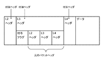
- the first method is a method of encapsulating a packet header with the same packet header as shown in FIG.
- a flag indicating that the pre-conversion header is added is provided in the option field (Options) of the IP header. .
- the second method is a method of storing the header in the option field (Options) of the IP header as shown in FIG. Also in the example of FIG. 9, a grant flag for identifying whether or not a pre-conversion header is given is provided. 8 and 9, the option field (Options) of the IP header is used, but the option field (Options) of the TCP header may be used. In the examples of FIGS. 8 and 9, the headers L2 to L4 are stored. However, it is not necessary to store all the headers, and only necessary fields in the headers may be stored.
- FIG. 10 is a flowchart showing the operation (initial setting) of the first exemplary embodiment of the present invention.
- the first switch 110 is referred to as a front switch
- the second switch 111 is referred to as a rear switch.
- the operator enters a cluster ID (CLID) in the redundant configuration management table, connection information between the appliances for which the redundant configuration is set and the upstream and downstream switches, information on the system operating as the active system, and appliance type. Information, a continuation flag, and a key field are registered (step S100).
- CLID cluster ID
- connection information between the appliances for which the redundant configuration is set and the upstream and downstream switches information on the system operating as the active system
- appliance type information on the system operating as the active system
- a continuation flag, and a key field are registered (step S100).
- the continuation flag and key field may be entered manually or automatically.
- the appliance type is Half-NAT (DNAT)
- the system may automatically determine that the continuation flag is No and the key field is nw_src.
- the continuation flag must be set to Yes whenever flow information cannot be uniquely identified before and after the appliance due to packet header conversion performed by the appliance.
- the appliance type is Full-NAT instead of Half-NAT as shown in FIG. 4
- the source IP address and the destination IP address are converted, so that the flow cannot be identified before and after the appliance. .
- the continuation flag Yes the pre-conversion header information is added by the preceding switch (first switch 110) and the pre-conversion header information is removed by the succeeding switch (second switch 111).
- control device can identify the flow.
- the key fields are nw_src and nw_dst, and in the case of NAPT, tp_src and tp_dst are added to the conditions.
- the control device 140 instructs the packet processing unit 130 to stop adding the pre-conversion header when both the ACT and SBY post-conversion header information are prepared in the header conversion table. (Deletion of the flow entry of No. 102 in FIG. 6 may be instructed.)
- the pre-switch first switch 110
- the pre-assignment flag see FIGS. 8 and 9
- the post-switch second switch 111
- the control device 140 discards the packet from the SBY in the flow table of the upstream switch (first switch 110) based on the information. No. Set to 1. Further, the control device 140 discards the ARP packet from the SBY in the flow table of the subsequent switch (second switch 111). 1 is set.
- the front and rear switch No. Assume that the flow entry of 0 is set when the control device and these switches are connected.
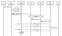
- Packet transfer 11 to 14 are sequence diagrams showing a series of operations according to the first embodiment of the present invention.
- the client CL1 transmits an ARP request packet addressed to VIP_L (virtual IP address on the input side of the appliance) at the start of communication (step s11).
- VIP_L virtual IP address on the input side of the appliance
- the pre-stage switch searches the flow table in the packet processing unit 130 (hereinafter simply referred to as “flow table”) for an entry having a matching condition that matches the received ARP request packet.
- flow table the packet processing unit 130
- the upstream switch transfers the ARP packet to the control device 140 according to the action (hereinafter, packet transfer processing from the switch to the control device (the flow entry The setting request process) is referred to as “packet-in”) (step s12).
- the control device 140 determines that the packet is an ARP request for the VIP_L of the appliance, and sends a flow entry that transmits the ARP packet to the AP 120 and the AP 121 (first switch) Switch 110).
- flow entries are set.
- the control device 140 sends a packet transmission request to the appliances AP120 and AP121 from the ports p1 and p2 of the upstream switch (first switch 110), respectively, and causes the upstream switch (first switch 110) to transmit a packet (hereinafter, referred to as “switching”). This process is called “packet out”) (step s13).
- Appliance AP 120, AP 121 receives the ARP packet and returns the MAC address for VIP_L as an ARP response packet (step s14).
- the pre-stage switch (first switch 110) sends the ARP response received from the AP 121 to No. 1 in FIG. Discard according to the flow entry 1 (step s15).
- the upstream switch (first switch 110) sends the ARP response received from the AP 120 to No. 1 in FIG. According to the flow entry of 0, it is transmitted to the control device 140 (step s16).
- the path control unit 141 of the control device 140 determines that the received packet is an ARP response from the appliance, and sets a flow entry that is output to the port of the upstream switch (first switch 110) that is the transmission destination.
- the transmission destination is CL1
- the output destination port is p0. 101 flow entries are set.
- the control device 140 packet-outs from the port p0 of the preceding switch (first switch 110) (step s17).
- the client CL1 receives the ARP response (step s18).
- the client CL1 Upon receiving the ARP response, the client CL1 transmits an IP packet to VIP_L as shown in FIG. 12 (step s19).
- Pre-stage switch (first switch 110) is No. According to the flow entry of 0, the received IP packet is transmitted to the control device 140 (step s20).
- the control device 140 determines that the received packet is an IP packet to the appliance, adds a pre-conversion header, converts the destination MAC address for each appliance, and transmits a flow entry that is transmitted to the AP 120 and the AP 121 to the upstream switch. Set to (first switch 110). Further, the control device 140 adds a pre-conversion header to the packet to the upstream switch (first switch 110), and causes the packet to be output from the ports p1 and p2 (step s21). Since the continuation flag in the redundant configuration management table is Yes, No. in FIG. Like the flow entry 102, a flow entry for adding a pre-conversion header adding process to the action is set. Since the continuation flag is Yes, the grant flag in the IP header is not used.
- Appliance AP120 and AP121 each convert and output the received packet based on its own NAT table (step s22).
- the post-stage switch (second switch 111) searches the flow table in the packet processing unit 131 for an entry having a matching condition that matches the received packet.
- the subsequent switch (second switch 111) transfers the received packet to the control device 140 according to the action (steps s23a and s23s).
- the control device 140 refers to the redundant configuration management table and determines from the input port information (import) of the received packet whether the received packet from the subsequent switch (second switch 111) is from ACT or SBY. Based on this, an entry of the header conversion table is registered.
- control device 140 When the control device 140 registers an entry in the header conversion table with the received packet from the ACT, the control device 140 sets a flow entry that causes the subsequent switch (second switch 111) to output the subsequent packet from the port p0. At this time, if the continuation flag in the redundant configuration management table is Yes, the control device 140 determines that the No. in FIG. As shown in the flow entry 101, a pre-conversion header removal action is added. Thereafter, the control device 140 removes the pre-conversion header and causes the subsequent switch (second switch 111) to packet out from the port p0 (step s24a).
- control device 140 sets a flow entry for discarding the subsequent packet and discards the packet (step s24s).
- the packet transferred via the AP 120 is received by SV1 (step s25a).
- the SV 1 that has received the packet transmits an ARP request packet to the VIP_R, which is the default GW, when transmitting a response packet to the IP_CL 1 (step s30).
- the post-stage switch (second switch 111) searches the flow table in the packet processing unit 131 for an entry having a matching condition that matches the received ARP packet.
- the subsequent switch (second switch 111) transfers the ARP packet to the control device 140 according to the action (step s31).
- the control device 140 determines that the packet is an ARP request for the VIP_R of the appliance, and sends a flow entry that transmits the ARP packet to the AP 120 and the AP 121 (second switch). Switch 111). Here, in FIG. 102 flow entries are set. Subsequently, the control device 140 causes the appliances AP120 and AP121 to transmit packets from the ports p1 and p2 of the subsequent switch (second switch 111) (step s32).
- Appliance AP 120, AP 121 receives the ARP packet and returns the MAC address for VIP_R as an ARP response packet (step s33).
- the subsequent switch (second switch 111) sends the ARP response received from the AP 121 to No. 1 in FIG. Discard according to the flow entry of 1 (step s34).
- the post-stage switch (second switch 111) sends the ARP response received from the AP 120 to No. 1 in FIG. According to the flow entry of 0, it transmits to the control apparatus 140 (step s35).
- the path control unit 141 of the control device 140 determines that the received packet is an ARP response from the appliance to the SV1, and sets a flow entry that is output to the port of the subsequent switch (second switch 111) serving as the transmission destination. .
- the output destination port is p0. 103 flow entries are set.
- the control device 140 packet-outs from the port p0 of the subsequent switch (second switch 111) (step s36).
- SV1 receives the ARP response.
- the SV 1 that has received the ARP response transmits an IP packet to VIP_R as shown in FIG. 14 (step s37).
- the rear switch (second switch 111) is No. According to the flow entry of 0, the received IP packet is transmitted to the control device 140 (step s38).
- the control device 140 determines that the received packet is an IP packet to CL1, converts the destination MAC address (dl_dst) to transmit the IP packet to the AP 120, and converts the destination MAC address (dl_dst) to transmit to the AP 121.
- the flow entry is set so that the source MAC address (dl_src) and the source IP address (nw_src) are converted and transmitted.
- flow entries are set.
- the control device 140 causes the subsequent switch (second switch 111) to perform the same process on the received packet, and then packet-outs from the ports p1 and p2 (step s39).
- the reason for performing the conversion at the time of transmission to the AP 121 is that it is necessary to show it as a return packet from the SV 2 with which the AP 121 communicated. Such information can be acquired from the route control unit 141.
- Appliances AP120 and AP121 each receive an IP packet, convert the packet header based on its own NAT table, and output the packet header to the upstream switch (first switch 110) (step s40).
- the pre-stage switch searches the flow table in the packet processing unit 130 for an entry having a matching condition that matches the received packet.
- the packet from the AP 121 is No. in FIG. Discarded according to the flow entry of 1 (step s41).
- the packet from AP 120 is No. in FIG. According to the flow entry of 0, it is transferred to the control device 140 (step s42).
- the control device 140 determines that the received packet is a return packet from the AP 120, and sets a flow entry for outputting the packet from the output port p0 in the upstream switch (first switch 110). Here, in FIG. 103 flow entries are set. The control device 140 instructs the upstream switch (first switch 110) to packet out (step s43).
- the response packet transferred via the AP 120 is received by CL1 (step s44).
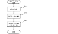
- FIG. 15 is a flowchart showing the operation (NAT table conversion) of the first exemplary embodiment of the present invention.
- the header of the packet that has passed through those appliances is the No. of the upstream switch (first switch 110) or the downstream switch (second switch 111). It is captured by a flow entry of 0 and transmitted to the control device 140.
- the NAT table of the AP 120 of the system 1 that is the current ACT is updated, and nw_dst is rewritten from IP_SV1 to IP_SV3.
- the packet is transmitted to the control device 140 (step S201).
- the control device 140 refers to the redundant configuration management table and identifies which appliance the received packet is output from.
- the SWID of the subsequent switch is sw2
- the input port information (import) is p1
- the entry with the CLID of 1 in the redundant configuration management table is applicable.
- the key field information of this entry is nw_src
- the value of the nw_src field in the header of the received packet is IP_CL1. From these results, the control device 140 confirms the No. of the header conversion table. 1 entry is specified. Next, the control device 140 determines the No. of the header conversion table.
- nw_dst is rewritten to IP_SV3 acquired from the header of the received packet (step S202).
- nw_dst which is the reverse of nw_src, is the key information. Since the continuation flag is Yes, the header conversion table entry may be specified based on the pre-conversion header.
- the control device 140 rewrites the flow entry of the subsequent switch (second switch 111) based on the information before and after rewriting the post-conversion header of the system 1.
- the match condition nw_dst of the flow entry is rewritten from IP_SV1 to IP_SV3.
- nw_src of the match condition of the flow entry 104 is rewritten from IP_SV1 to IP_SV3.
- the control device 140 causes the subsequent switch (second switch 111) to packet out from the port p0 (step S203).
- the control device 140 refers to the redundant configuration management table from the received notification, refers to the entry whose CLID is 1, changes the current ACT (active system) to the system 2, and connects the connection port and key field information of the system 1 Nw_src is obtained.
- the control device 140 refers to the header conversion table, and obtains a list of nw_src having a CLID of 1 and an active system field of system 1.
- the header conversion table No. 1 entry corresponds.
- FIG. 16 is a diagram showing the updated redundant configuration management table, and the broken lines indicate the changed locations.
- the control device 140 discards the ARP packet for the connection port p2 of the system 2 that was the previous SBY No.
- the input port information (import) of the match condition is changed to the connection port p1 of the new SBY.
- the input port information (import) of the match condition is changed to the connection port p2 of the new ACT.
- the rear-stage switch (second switch 111) transfers the communication packet with the AP 121 that is the new ACT (while converting the packet header), and discards the communication packet of the AP 120 that is the previous ACT.
- FIG. 18 is a diagram showing a flow entry of the post-update switch (second switch 111) after the update, and a broken line shows a changed part.
- the control device 140 rewrites related ones of the flow entries of the upstream switch (first switch 110) (see FIG. 7). Specifically, the control device 140 transfers the ARP packet No. for transferring the ARP packet with respect to the connection port p1 of the system 1 that was the former ACT. For the flow entry 101, the input port information (import) of the match condition is changed to the connection port p2 of the new ACT. Next, the control device 140 discards the ARP packet for the connection port p2 of the system 2 that has been SBY. For one flow entry, the input port information (import) of the match condition is changed to the connection port p1 of the new SBY. Furthermore, the control device 140 transfers the reply packet from the previous ACT to CL1. For the flow entry 103, the input port information (import) of the match condition is changed to p2.
- FIG. 17 is a diagram showing the flow entry of the previous-stage switch (first switch 110) after the update, and the broken line shows the changed part.
- the upstream switch (first switch 110) transfers the communication packet with the new ACT AP 121 (while converting the packet header), and discards the communication packet of the previous ACT AP 120.
- the difference in header conversion between the AP 120 system and the AP 121 system is absorbed by the post-stage switch (second switch 111).
- the post-stage switch (second switch 111) As a result, even if the ACT and SBY appliances are different models, stateful failover can be realized.
- the appliance to be made redundant is sandwiched between the front switch (first switch 110) and the rear switch (second switch 111), stateful failover between different models can be realized. The degree of freedom is increased and the flexibility of physical resource allocation is improved.
- the present invention is not limited to the above-described embodiments, and further modifications, substitutions, and adjustments may be made without departing from the basic technical idea of the present invention. Can be added.
- the client CL1 is connected to the upstream switch (first switch 110), and the servers SV1 to SV3 are connected to the downstream switch (second switch 111) via the switch 112.
- first switch 110 the upstream switch
- second switch 111 the downstream switch
- Control device 110 First switch 111 Second switch 112 Switch 120, 121 Appliance (AP) 130, 131 Packet processing unit 140 Control device 141 Route control unit 142 Conversion rule management unit p0, p1, p2 Port CL1 Client SV1 to SV3 server
Landscapes
- Engineering & Computer Science (AREA)
- Computer Networks & Wireless Communication (AREA)
- Signal Processing (AREA)
- Computer Security & Cryptography (AREA)
- Data Exchanges In Wide-Area Networks (AREA)
Description
本発明は、日本国特許出願:特願2012-079953号(2012年 3月30日出願)の優先権主張に基づくものであり、同出願の全記載内容は引用をもって本書に組み込み記載されているものとする。
本発明は、ネットワークアプライアンス冗長化システム、制御装置、ネットワークアプライアンス冗長化方法及びプログラムに関し、特に、2つの異なる機種のネットワークアプライアンスが配置されているネットワークアプライアンス冗長化システム、制御装置、ネットワークアプライアンス冗長化方法及びプログラムに関する。
続いて、本発明の第1の実施形態について図面を参照して詳細に説明する。以下、アプライアンスとしてHalf-NATを行うロードバランサ(以降、「LB」と称する。)を冗長化する例を取り上げる。なお、本発明はこの実施形態に限定されるものではなく、その他ヘッダ変換を伴うアプライアンスの冗長化を行う際に適用可能である。
[初期設定]
はじめに、図2に示した制御装置140や第1、第2スイッチ110、111に対して行われる初期設定について説明する。図10は、本発明の第1の実施形態の動作(初期設定)を表した流れ図である。以下、第1スイッチ110を前段スイッチと呼び、第2スイッチ111を後段スイッチと呼んで説明する。
[パケット転送]
図11~図14は、本発明の第1の実施形態の一連の動作を表したシーケンス図である。図11に示すように、クライアントCL1は、通信開始に当たって、VIP_L(アプライアンスの入力側の仮想IPアドレス)宛てにARP要求パケットを送信する(ステップs11)。
続いて、アプライアンスAP120、AP121において、NATテーブルの更新が行われた場合の処理について説明する。図15は、本発明の第1の実施形態の動作(NATテーブル変換)を表した流れ図である。
続いて、AP120とAP121のACTとSBYの切り替えが行われた場合の動作について説明する。冗長構成を組むAP120とAP121のアプライアンスのうち、AP120に障害が発生した場合、制御装置140は、その通知を受け取る。この方法には、SNMP(Simple Network Management Protocol)のTrapやアプライアンスから情報を受ける、アプライアンスを経由するパケットを監視する、または、ハートビートによる生存確認、などの方法があるが、特にこれらに限定するものではない。
また日本語は単複同形であり、単数で記載された用語は複数も代表する。
30 第1のスイッチ
31 第2のスイッチ
40 制御装置
110 第1スイッチ
111 第2スイッチ
112 スイッチ
120、121 アプライアンス(AP)
130、131 パケット処理部
140 制御装置
141 経路制御部
142 変換ルール管理部
p0、p1、p2 ポート
CL1 クライアント
SV1~SV3 サーバ
Claims (9)
- 現用系と予備系とに切り替えて運用される2つの異なる機種のネットワークアプライアンスの前段に配置される第1のスイッチと、
前記2つの異なる機種のネットワークアプライアンスの後段に配置される第2のスイッチと、
前記第1のスイッチから送信されたパケットのヘッダ情報と、前記現用系のネットワークアプライアンスを経由して前記第2のスイッチにて受信したパケットのヘッダ情報と、に基づいて、前記現用系のネットワークアプライアンスによるヘッダ変換ルールを学習する変換ルール管理部を備え、前記予備系のネットワークアプライアンスに切り替わった際に、前記ヘッダ変換ルールに基づいて、前記第2のスイッチに対し、前記現用系のネットワークアプライアンスと同様の出力パケットとなるようヘッダ書き換えを指示する制御装置と、を含むネットワークアプライアンス冗長化システム。 - 前記第1、2のスイッチは、
受信パケットと照合するためのマッチング条件と、処理内容とを対応付けた制御情報を記憶する制御情報記憶部と、
前記制御情報記憶部に記憶された制御情報の中から、受信パケットに適合するマッチング条件を持つ制御情報に定められた処理内容を実行するパケット処理部とを備え、
前記制御装置は、前記第1、2のスイッチの制御情報記憶部の制御情報を書き換えることにより、前記第1のスイッチから送信されたパケットのヘッダ情報と、前記第2のスイッチにて受信したパケットのヘッダ情報と、を受け取るネットワークアプライアンス冗長化システム。 - 前記制御装置は、
前記第1のスイッチに、前記現用系のネットワークアプライアンスによる変更前後のヘッダ情報を格納可能なパケットを送信させる制御情報を設定し、
前記第2のスイッチに、前記現用系のネットワークアプライアンスによってヘッダ情報が書き換えられたパケットを転送させる制御情報を設定することにより、
前記現用系のネットワークアプライアンスによるヘッダ変換ルールを学習する請求項2のネットワークアプライアンス冗長化システム。 - 前記制御装置は、
前記制御情報を用いて、前記第1、第2のスイッチに対して、ヘッダ書き換えを指示する請求項2又は3のネットワークアプライアンス冗長化システム。 - 前記制御装置は、
前記第2のスイッチからの通知に基づいて、アドレス変換テーブルの更新有無を検出し、前記変換ルール管理部に保持されているヘッダ変換ルールを更新するとともに、前記第2のスイッチに対し、前記現用系のネットワークアプライアンスと同様の出力パケットとなるようヘッダ書き換えを指示する請求項1から4いずれか一のネットワークアプライアンス冗長化システム。 - 前記ネットワークアプライアンスは、NAT装置、NAPT装置、ロードバランサのいずれかである請求項1から5いずれか一のネットワークアプライアンス冗長化システム。
- 現用系と予備系とに切り替えて運用される2つの異なる機種のネットワークアプライアンスの前段に配置される第1のスイッチと、
前記2つの異なる機種のネットワークアプライアンスの後段に配置される第2のスイッチと、に接続され、
前記第1のスイッチから送信されたパケットと、前記現用系のネットワークアプライアンスを経由して前記第2のスイッチにて受信したパケットと、に基づいて、前記現用系のネットワークアプライアンスによるヘッダ変換ルールを学習する変換ルール管理部を備え、
前記予備系のネットワークアプライアンスに切り替わった際に、前記ヘッダ変換ルールに基づいて、前記第2のスイッチに対し、前記現用系のネットワークアプライアンスと同様の出力パケットとなるようヘッダ書き換えを指示する制御装置。 - 現用系と予備系とに切り替えて運用される2つの異なる機種のネットワークアプライアンスの前段に配置される第1のスイッチと、前記2つの異なる機種のネットワークアプライアンスの後段に配置される第2のスイッチと、接続された制御装置が、
前記第1のスイッチから送信されたパケットのヘッダ情報と、前記現用系のネットワークアプライアンスを経由して前記第2のスイッチにて受信したパケットのヘッダ情報と、に基づいて、前記現用系のネットワークアプライアンスによるヘッダ変換ルールを学習するステップと、
前記現用系のネットワークアプライアンスから前記予備系のネットワークアプライアンスに切り替わった際に、前記ヘッダ変換ルールに基づいて、前記第2のスイッチに対し前記第1のスイッチと同様のヘッダ書き換えを指示するステップとを含む制御装置と、を含むネットワークアプライアンス冗長化方法。 - 現用系と予備系とに切り替えて運用される2つの異なる機種のネットワークアプライアンスの前段に配置される第1のスイッチと、前記2つの異なる機種のネットワークアプライアンスの後段に配置される第2のスイッチと、接続された制御装置に搭載されたコンピュータに、
前記第1のスイッチから送信されたパケットのヘッダ情報と、前記現用系のネットワークアプライアンスを経由して前記第2のスイッチにて受信したパケットのヘッダ情報と、に基づいて、前記現用系のネットワークアプライアンスによるヘッダ変換ルールを学習する処理と、
前記現用系のネットワークアプライアンスから前記予備系のネットワークアプライアンスに切り替わった際に、前記ヘッダ変換ルールに基づいて、前記第2のスイッチに対し前記第1のスイッチと同様のヘッダ書き換えを指示する処理とを実行させるプログラム。
Priority Applications (4)
| Application Number | Priority Date | Filing Date | Title |
|---|---|---|---|
| US14/389,337 US9401865B2 (en) | 2012-03-30 | 2013-03-29 | Network appliance redundancy system, control apparatus, network appliance redundancy method and program |
| JP2014508106A JP5861772B2 (ja) | 2012-03-30 | 2013-03-29 | ネットワークアプライアンス冗長化システム、制御装置、ネットワークアプライアンス冗長化方法及びプログラム |
| CN201380017998.XA CN104247342A (zh) | 2012-03-30 | 2013-03-29 | 网络设备冗余化系统、控制装置、网络设备冗余化方法及程序 |
| EP13767523.7A EP2833583A4 (en) | 2012-03-30 | 2013-03-29 | REDUNDANCY SYSTEM FOR NETWORK DEVICE, CONTROL DEVICE, REDUNDANCY PROCESS FOR NETWORK APPLICATION AND PROGRAM |
Applications Claiming Priority (2)
| Application Number | Priority Date | Filing Date | Title |
|---|---|---|---|
| JP2012079953 | 2012-03-30 | ||
| JP2012-079953 | 2012-03-30 |
Publications (1)
| Publication Number | Publication Date |
|---|---|
| WO2013147193A1 true WO2013147193A1 (ja) | 2013-10-03 |
Family
ID=49260434
Family Applications (1)
| Application Number | Title | Priority Date | Filing Date |
|---|---|---|---|
| PCT/JP2013/059605 Ceased WO2013147193A1 (ja) | 2012-03-30 | 2013-03-29 | ネットワークアプライアンス冗長化システム、制御装置、ネットワークアプライアンス冗長化方法及びプログラム |
Country Status (5)
| Country | Link |
|---|---|
| US (1) | US9401865B2 (ja) |
| EP (1) | EP2833583A4 (ja) |
| JP (1) | JP5861772B2 (ja) |
| CN (1) | CN104247342A (ja) |
| WO (1) | WO2013147193A1 (ja) |
Cited By (1)
| Publication number | Priority date | Publication date | Assignee | Title |
|---|---|---|---|---|
| JP2015231059A (ja) * | 2014-06-03 | 2015-12-21 | 富士通株式会社 | 経路設定装置及び経路設定方法 |
Families Citing this family (8)
| Publication number | Priority date | Publication date | Assignee | Title |
|---|---|---|---|---|
| JP6330479B2 (ja) * | 2014-05-23 | 2018-05-30 | 富士通株式会社 | 情報処理システム及び情報処理方法 |
| US9929937B2 (en) * | 2015-08-27 | 2018-03-27 | Dell Products L.P. | Layer 3 routing loop prevention system |
| CN108574626A (zh) * | 2017-03-13 | 2018-09-25 | 中兴通讯股份有限公司 | 一种分布式nat双机热备份流量切换系统和方法 |
| US10581730B2 (en) | 2018-07-12 | 2020-03-03 | Vmware, Inc. | Packet processing using service chains |
| US10645201B2 (en) * | 2018-07-31 | 2020-05-05 | Vmware, Inc. | Packet handling during service virtualized computing instance migration |
| US11212322B2 (en) * | 2018-10-10 | 2021-12-28 | Rockwelll Automation Technologies, Inc. | Automated discovery of security policy from design data |
| JP7099272B2 (ja) * | 2018-11-19 | 2022-07-12 | 富士通株式会社 | 情報処理装置、ネットワークシステム及びチーミングプログラム |
| US20240031292A1 (en) * | 2022-07-25 | 2024-01-25 | Vmware, Inc. | Network flow based load balancing |
Citations (4)
| Publication number | Priority date | Publication date | Assignee | Title |
|---|---|---|---|---|
| JP2005303501A (ja) | 2004-04-08 | 2005-10-27 | Hitachi Ltd | パケット転送装置 |
| JP2007208502A (ja) | 2006-01-31 | 2007-08-16 | Nec Infrontia Corp | 通信システム、バックアップルータ、その冗長化処理プログラムおよびその冗長化処理方法 |
| JP2010114585A (ja) * | 2008-11-05 | 2010-05-20 | Mitsubishi Electric Corp | Nat装置 |
| WO2011093288A1 (ja) * | 2010-02-01 | 2011-08-04 | 日本電気株式会社 | ネットワークシステム、コントローラ、ネットワーク制御方法 |
Family Cites Families (7)
| Publication number | Priority date | Publication date | Assignee | Title |
|---|---|---|---|---|
| US7280557B1 (en) * | 2002-06-28 | 2007-10-09 | Cisco Technology, Inc. | Mechanisms for providing stateful NAT support in redundant and asymetric routing environments |
| US8332464B2 (en) * | 2002-12-13 | 2012-12-11 | Anxebusiness Corp. | System and method for remote network access |
| CN101141494B (zh) * | 2007-10-12 | 2011-02-02 | 杭州华三通信技术有限公司 | 一种解决负载分担情况下资源分配冲突的方法 |
| CN101834831A (zh) * | 2009-03-13 | 2010-09-15 | 华为技术有限公司 | 一种实现nat设备冗余备份的方法、装置和系统 |
| JP5169992B2 (ja) * | 2009-05-27 | 2013-03-27 | Necインフロンティア株式会社 | ネットワーク、ネットワーク装置及びそれらに用いる負荷分散方法 |
| JP5645139B2 (ja) | 2010-01-05 | 2014-12-24 | 日本電気株式会社 | ネットワークシステム、コントローラ、ネットワーク制御方法 |
| JP5413517B2 (ja) * | 2010-08-20 | 2014-02-12 | 日本電気株式会社 | 通信システム、制御装置、通信方法およびプログラム |
-
2013
- 2013-03-29 US US14/389,337 patent/US9401865B2/en active Active
- 2013-03-29 WO PCT/JP2013/059605 patent/WO2013147193A1/ja not_active Ceased
- 2013-03-29 JP JP2014508106A patent/JP5861772B2/ja not_active Expired - Fee Related
- 2013-03-29 CN CN201380017998.XA patent/CN104247342A/zh active Pending
- 2013-03-29 EP EP13767523.7A patent/EP2833583A4/en not_active Withdrawn
Patent Citations (4)
| Publication number | Priority date | Publication date | Assignee | Title |
|---|---|---|---|---|
| JP2005303501A (ja) | 2004-04-08 | 2005-10-27 | Hitachi Ltd | パケット転送装置 |
| JP2007208502A (ja) | 2006-01-31 | 2007-08-16 | Nec Infrontia Corp | 通信システム、バックアップルータ、その冗長化処理プログラムおよびその冗長化処理方法 |
| JP2010114585A (ja) * | 2008-11-05 | 2010-05-20 | Mitsubishi Electric Corp | Nat装置 |
| WO2011093288A1 (ja) * | 2010-02-01 | 2011-08-04 | 日本電気株式会社 | ネットワークシステム、コントローラ、ネットワーク制御方法 |
Non-Patent Citations (4)
| Title |
|---|
| "OpenFlow Switch Specification", VERSION 1.1.0 IMPLEMENTED (WIRE PROTOCOL 0X02) [ONLINE, 14 February 2012 (2012-02-14), Retrieved from the Internet <URL:http://www.openflow.org/documents/openflow-spec-vl.I.O.pdf> |
| KARINO SHUICHI; SUZUKI KAZUYA; JIBIKI MASAHIRO: "Duplicated Redundancy and Packet Processing Method in Router Clusters (Internet and general", IEICE (THE INSTITUTE OF ELECTRONICS, INFORMATION AND COMMUNICATION ENGINEERS) TECHNICAL REPORT, IA, INTERNET ARCHITECTURE, vol. 104, no. 377, 21 October 2004 (2004-10-21), pages 21 - 26 |
| NICK MCKEOWN, OPENFLOW: ENABLING INNOVATION IN CAMPUS NETWORKS, 14 February 2012 (2012-02-14), Retrieved from the Internet <URL:http://www.openflow.org/documents/openflow-wp-latest.pdf> |
| See also references of EP2833583A4 |
Cited By (1)
| Publication number | Priority date | Publication date | Assignee | Title |
|---|---|---|---|---|
| JP2015231059A (ja) * | 2014-06-03 | 2015-12-21 | 富士通株式会社 | 経路設定装置及び経路設定方法 |
Also Published As
| Publication number | Publication date |
|---|---|
| US9401865B2 (en) | 2016-07-26 |
| JPWO2013147193A1 (ja) | 2015-12-14 |
| JP5861772B2 (ja) | 2016-02-16 |
| EP2833583A4 (en) | 2015-12-09 |
| CN104247342A (zh) | 2014-12-24 |
| US20150055656A1 (en) | 2015-02-26 |
| EP2833583A1 (en) | 2015-02-04 |
Similar Documents
| Publication | Publication Date | Title |
|---|---|---|
| JP5861772B2 (ja) | ネットワークアプライアンス冗長化システム、制御装置、ネットワークアプライアンス冗長化方法及びプログラム | |
| US9215175B2 (en) | Computer system including controller and plurality of switches and communication method in computer system | |
| JP5648926B2 (ja) | ネットワークシステム、コントローラ、ネットワーク制御方法 | |
| EP3248331B1 (en) | Method for controlling switches to capture and monitor network traffic | |
| JP6445015B2 (ja) | ミドルウェアおよびアプリケーションの実行のためにエンジニアド・システムにおいてデータサービスを提供するためのシステムおよび方法 | |
| JP6004405B2 (ja) | コントローラでネットワークパケット転送を管理するシステム及び方法 | |
| EP2748992B1 (en) | Method for managing network hardware address requests with a controller | |
| JP5585660B2 (ja) | 通信システム、制御装置、処理規則の設定方法およびプログラム | |
| US8938521B2 (en) | Bi-directional synchronization enabling active-active redundancy for load-balancing switches | |
| US9008080B1 (en) | Systems and methods for controlling switches to monitor network traffic | |
| US9787567B1 (en) | Systems and methods for network traffic monitoring | |
| WO2011087085A1 (ja) | 計算機、ネットワーク接続切替え方法およびプログラム | |
| JP2017506025A (ja) | ネットワークサービス挿入を実行するシステム及び方法 | |
| JP6070700B2 (ja) | パケット転送システム、制御装置、パケット転送方法及びプログラム | |
| WO2014175423A1 (ja) | 通信ノード、通信システム、パケット処理方法及びプログラム | |
| JPWO2014126094A1 (ja) | 通信システム、通信方法、制御装置、制御装置の制御方法及びプログラム | |
| EP3503474A1 (en) | A method for remotely performing a network function on data exchanged with at least one gateway | |
| HK1180494A (en) | Computer system and communication method in computer system | |
| JP2016225933A (ja) | 制御装置、中継装置の制御方法、プログラム及び通信システム | |
| WO2014142081A1 (ja) | 転送ノード、制御装置、通信システム、パケット処理方法及びプログラム |
Legal Events
| Date | Code | Title | Description |
|---|---|---|---|
| 121 | Ep: the epo has been informed by wipo that ep was designated in this application |
Ref document number: 13767523 Country of ref document: EP Kind code of ref document: A1 |
|
| ENP | Entry into the national phase |
Ref document number: 2014508106 Country of ref document: JP Kind code of ref document: A |
|
| WWE | Wipo information: entry into national phase |
Ref document number: 14389337 Country of ref document: US |
|
| NENP | Non-entry into the national phase |
Ref country code: DE |
|
| REEP | Request for entry into the european phase |
Ref document number: 2013767523 Country of ref document: EP |
|
| WWE | Wipo information: entry into national phase |
Ref document number: 2013767523 Country of ref document: EP |