WO2013147273A1 - ハニカム構造体の発熱方法 - Google Patents
ハニカム構造体の発熱方法 Download PDFInfo
- Publication number
- WO2013147273A1 WO2013147273A1 PCT/JP2013/059774 JP2013059774W WO2013147273A1 WO 2013147273 A1 WO2013147273 A1 WO 2013147273A1 JP 2013059774 W JP2013059774 W JP 2013059774W WO 2013147273 A1 WO2013147273 A1 WO 2013147273A1
- Authority
- WO
- WIPO (PCT)
- Prior art keywords
- honeycomb structure
- heat generation
- temperature
- power
- heating
- Prior art date
- Legal status (The legal status is an assumption and is not a legal conclusion. Google has not performed a legal analysis and makes no representation as to the accuracy of the status listed.)
- Ceased
Links
Images


Classifications
-
- H—ELECTRICITY
- H05—ELECTRIC TECHNIQUES NOT OTHERWISE PROVIDED FOR
- H05B—ELECTRIC HEATING; ELECTRIC LIGHT SOURCES NOT OTHERWISE PROVIDED FOR; CIRCUIT ARRANGEMENTS FOR ELECTRIC LIGHT SOURCES, IN GENERAL
- H05B3/00—Ohmic-resistance heating
- H05B3/0004—Devices wherein the heating current flows through the material to be heated
-
- F—MECHANICAL ENGINEERING; LIGHTING; HEATING; WEAPONS; BLASTING
- F01—MACHINES OR ENGINES IN GENERAL; ENGINE PLANTS IN GENERAL; STEAM ENGINES
- F01N—GAS-FLOW SILENCERS OR EXHAUST APPARATUS FOR MACHINES OR ENGINES IN GENERAL; GAS-FLOW SILENCERS OR EXHAUST APPARATUS FOR INTERNAL-COMBUSTION ENGINES
- F01N9/00—Electrical control of exhaust gas treating apparatus
-
- F—MECHANICAL ENGINEERING; LIGHTING; HEATING; WEAPONS; BLASTING
- F01—MACHINES OR ENGINES IN GENERAL; ENGINE PLANTS IN GENERAL; STEAM ENGINES
- F01N—GAS-FLOW SILENCERS OR EXHAUST APPARATUS FOR MACHINES OR ENGINES IN GENERAL; GAS-FLOW SILENCERS OR EXHAUST APPARATUS FOR INTERNAL-COMBUSTION ENGINES
- F01N3/00—Exhaust or silencing apparatus having means for purifying, rendering innocuous, or otherwise treating exhaust
- F01N3/08—Exhaust or silencing apparatus having means for purifying, rendering innocuous, or otherwise treating exhaust for rendering innocuous
- F01N3/10—Exhaust or silencing apparatus having means for purifying, rendering innocuous, or otherwise treating exhaust for rendering innocuous by thermal or catalytic conversion of noxious components of exhaust
- F01N3/18—Exhaust or silencing apparatus having means for purifying, rendering innocuous, or otherwise treating exhaust for rendering innocuous by thermal or catalytic conversion of noxious components of exhaust characterised by methods of operation; Control
- F01N3/20—Exhaust or silencing apparatus having means for purifying, rendering innocuous, or otherwise treating exhaust for rendering innocuous by thermal or catalytic conversion of noxious components of exhaust characterised by methods of operation; Control specially adapted for catalytic conversion
- F01N3/2006—Periodically heating or cooling catalytic reactors, e.g. at cold starting or overheating
- F01N3/2013—Periodically heating or cooling catalytic reactors, e.g. at cold starting or overheating using electric or magnetic heating means
- F01N3/2026—Periodically heating or cooling catalytic reactors, e.g. at cold starting or overheating using electric or magnetic heating means directly electrifying the catalyst substrate, i.e. heating the electrically conductive catalyst substrate by joule effect
-
- B—PERFORMING OPERATIONS; TRANSPORTING
- B29—WORKING OF PLASTICS; WORKING OF SUBSTANCES IN A PLASTIC STATE IN GENERAL
- B29D—PRODUCING PARTICULAR ARTICLES FROM PLASTICS OR FROM SUBSTANCES IN A PLASTIC STATE
- B29D99/00—Subject matter not provided for in other groups of this subclass
- B29D99/0089—Producing honeycomb structures
-
- B—PERFORMING OPERATIONS; TRANSPORTING
- B29—WORKING OF PLASTICS; WORKING OF SUBSTANCES IN A PLASTIC STATE IN GENERAL
- B29L—INDEXING SCHEME ASSOCIATED WITH SUBCLASS B29C, RELATING TO PARTICULAR ARTICLES
- B29L2022/00—Hollow articles
- B29L2022/005—Hollow articles having dividing walls, e.g. additional elements placed between object parts
- B29L2022/007—Hollow articles having dividing walls, e.g. additional elements placed between object parts integrally moulded or formed
-
- Y—GENERAL TAGGING OF NEW TECHNOLOGICAL DEVELOPMENTS; GENERAL TAGGING OF CROSS-SECTIONAL TECHNOLOGIES SPANNING OVER SEVERAL SECTIONS OF THE IPC; TECHNICAL SUBJECTS COVERED BY FORMER USPC CROSS-REFERENCE ART COLLECTIONS [XRACs] AND DIGESTS
- Y02—TECHNOLOGIES OR APPLICATIONS FOR MITIGATION OR ADAPTATION AGAINST CLIMATE CHANGE
- Y02T—CLIMATE CHANGE MITIGATION TECHNOLOGIES RELATED TO TRANSPORTATION
- Y02T10/00—Road transport of goods or passengers
- Y02T10/10—Internal combustion engine [ICE] based vehicles
- Y02T10/12—Improving ICE efficiencies
-
- Y—GENERAL TAGGING OF NEW TECHNOLOGICAL DEVELOPMENTS; GENERAL TAGGING OF CROSS-SECTIONAL TECHNOLOGIES SPANNING OVER SEVERAL SECTIONS OF THE IPC; TECHNICAL SUBJECTS COVERED BY FORMER USPC CROSS-REFERENCE ART COLLECTIONS [XRACs] AND DIGESTS
- Y02—TECHNOLOGIES OR APPLICATIONS FOR MITIGATION OR ADAPTATION AGAINST CLIMATE CHANGE
- Y02T—CLIMATE CHANGE MITIGATION TECHNOLOGIES RELATED TO TRANSPORTATION
- Y02T10/00—Road transport of goods or passengers
- Y02T10/10—Internal combustion engine [ICE] based vehicles
- Y02T10/40—Engine management systems
Definitions
- the present invention relates to a heating method for a honeycomb structure. More specifically, the present invention relates to a heating method for a honeycomb structure that can cause the honeycomb structure to generate heat satisfactorily with little power consumption and low power consumption.
- a honeycomb structure made of conductive ceramics and having electrodes disposed on both ends is used as a catalyst carrier with a heater (see, for example, Patent Document 3).
- a honeycomb structure including a porous honeycomb structure having a cylindrical honeycomb structure portion having an outer peripheral wall located at the outermost periphery, and a pair of electrode portions disposed on the side surfaces of the honeycomb structure portion.
- the electrical resistivity of the honeycomb structure part is 1 to 200 ⁇ cm.
- the honeycomb structure portion When a catalyst is supported on a honeycomb structure as described in Patent Document 4 to treat exhaust gas, the honeycomb structure portion must be quickly heated so as to be in time for the start of an automobile engine.
- the engine In particular, in a hybrid vehicle having a power source other than the engine, the engine is frequently started and stopped. Therefore, it is necessary to quickly generate heat at the honeycomb structure in accordance with the start of the engine. Further, even in a general gasoline engine automobile or the like, in a traveling state where the engine is frequently started and stopped, it is necessary to quickly generate heat at the honeycomb structure in accordance with the engine start.
- the above-described conventional heating method for a honeycomb structure has a problem that it is extremely difficult to generate heat uniformly in the honeycomb structure.
- the resistance value of the honeycomb structure portion decreases as the temperature rises, heat generation at a location where the temperature is high is further promoted.
- the partial temperature difference of the honeycomb structure portion increases as the temperature rises, and the temperature difference between the maximum temperature and the minimum temperature when the target temperature is reached widens greatly. There was a case.
- the desired temperature mentioned above can include a catalyst activation temperature.
- the honeycomb structure part it is not preferable from the viewpoint of power consumption to cause the honeycomb structure part to generate heat excessively beyond the catalyst activation temperature.
- the lowest temperature in the heat generating portion reaches the catalyst activation temperature, if the maximum temperature in the heat generating portion greatly exceeds the catalyst activation temperature, power is wasted for heat generation in the honeycomb structure portion. It turns out that.
- the honeycomb structure is heated using a power source such as a battery. Therefore, it is important to effectively use the limited power to generate heat in the honeycomb structure.
- the present invention has been made in view of the above-described problems, and provides a heating method for a honeycomb structure that can cause the honeycomb structure to generate heat satisfactorily with little power consumption and low power consumption. .
- the present invention provides the following heat generation method for a honeycomb structure.
- a cylindrical honeycomb that has a porous partition wall defining a plurality of cells extending from the first end surface to the second end surface, which serves as a fluid flow path, and an outer peripheral wall located at the outermost periphery, and generates heat when energized.
- a heating step of supplying electric power to the honeycomb structure part of the honeycomb structure including the structure part and a catalyst supported on the partition walls of the honeycomb structure part to generate heat to the target temperature of the honeycomb structure part In the heat generation step, before the lowest temperature at the heat generation portion of the honeycomb structure portion reaches the target temperature, the supply of power to the honeycomb structure portion is stopped or the power supplied to the honeycomb structure portion is reduced.
- a method for heat generation of a honeycomb structure in which a supply power reduction section is provided at least once.
- a supply power return section that restarts the supply of power to the honeycomb structure part or increases the power supplied to the honeycomb structure part from a reduced state.
- honeycomb structure according to any one of [1] to [3], wherein, in the heat generation step, the honeycomb structure portion generates heat so that a maximum temperature at a heat generation portion of the honeycomb structure portion does not exceed 1000 ° C. How to heat up the body.
- honeycomb structure according to any one of [1] to [5], wherein the honeycomb structure further includes two or more electrode portions disposed on a side surface of the honeycomb structure portion. Heat generation method.
- the supply power decrease section is provided in a state where at least the highest temperature in the heat generation portion of the honeycomb structure portion is equal to or higher than the target temperature.
- the above-described supply power reduction section is provided at least once before the minimum temperature at the heating portion of the honeycomb structure reaches the target temperature.
- the difference between the maximum temperature and the minimum temperature of the honeycomb structure at the end of the heating process for heating the honeycomb structure to the target temperature can be reduced.
- the partial temperature difference of the honeycomb structure is reduced (that is, the minimum temperature is made higher). , It can be brought close to the maximum temperature).
- the temperature difference at the time when the heat generation process is completed can be reduced, it requires heat generation as compared with the case where heat is generated so that the lowest temperature becomes the same temperature by the conventional method. There is also an effect that less power is required.
- the maximum temperature is lower than in the case where heat is generated so that the minimum temperature becomes the same temperature by the conventional method, the temperature difference of the honeycomb structure can be made smaller as a result.
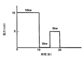
- FIG. 4 is a graph showing an example of the relationship between the power (kW) supplied to the honeycomb structure and the elapsed time (seconds) of the heating process in the heating process of one embodiment of the heating method of the honeycomb structure of the present invention.
- 4 is a graph showing an example of the relationship between the temperature of the honeycomb structure and the elapsed time (seconds) of the heating process in the heating process of the embodiment of the heating method of the honeycomb structure of the present invention.
- FIG. 6 is a graph showing another example of the relationship between the power (kW) supplied to the honeycomb structure and the elapsed time (seconds) of the heating process in the heating process of one embodiment of the heating method of the honeycomb structure of the present invention. is there.
- the graph which shows the further another example of the relationship between the electric power (kW) supplied to a honeycomb structure part, and the elapsed time (second) of a heat generation process in the heat generation process of one embodiment of the heat generation method of the honeycomb structure of the present invention. It is.
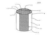
- FIG. 3 is a perspective view schematically showing a honeycomb structure used in the heating method for a honeycomb structure of the present invention.
- FIG. 8 is a schematic diagram showing a cross section of the honeycomb structure shown in FIG. 7 parallel to the cell extending direction.
- FIG. 8 is a schematic view showing a cross section of the honeycomb structure shown in FIG. 7 orthogonal to the cell extending direction.
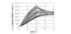
- 4 is a graph showing the relationship between the temperature (° C.) of the honeycomb structure portion and the elapsed time (seconds) of the heating process in the heating process of the heating method of the honeycomb structure of Example 1.
- 6 is a graph showing the relationship between the power (kW) supplied to the honeycomb structure and the elapsed time (seconds) of the heating process in the heating process of the heating method of the honeycomb structure of Example 1.
- 6 is a graph showing the relationship between the temperature (° C.) of the honeycomb structure portion and the elapsed time (seconds) of the heating process in the heating process of the heating method of the honeycomb structure of Example 2.
- 6 is a graph showing the relationship between the power (kW) supplied to the honeycomb structure and the elapsed time (seconds) of the heating process in the heating process of the heating method of the honeycomb structure of Example 2.
- 4 is a graph showing the relationship between the temperature (° C.) of the honeycomb structure portion and the elapsed time (seconds) of the heating process in the heating process of the heating method of the honeycomb structure of Comparative Example 1.
- 6 is a graph showing the relationship between the power (kW) supplied to the honeycomb structure and the elapsed time (seconds) of the heating process in the heating process of the heating method of the honeycomb structure of Comparative Example 1.
- a heat generation method of honeycomb structure is a heating method for a honeycomb structure performed using a honeycomb structure 100 as shown in FIG.
- a honeycomb structure 100 shown in FIG. 1 includes a cylindrical honeycomb structure portion 4 that generates heat when energized, and a catalyst 7 supported on the partition walls 1 of the honeycomb structure portion 4.
- the honeycomb structure portion 4 has a porous partition wall 1 and an outer peripheral wall 3 located at the outermost periphery.
- a plurality of cells 2 extending from a first end surface 11 that is one end surface serving as a fluid flow path to a second end surface 12 that is the other end surface are partitioned by the porous partition wall 1.
- FIG. 1 is a schematic diagram for explaining a heat generation process of an embodiment of the heat generation method of the honeycomb structure of the present invention.
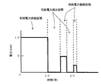
- FIG. 2 shows an example of the relationship between the power (kW) supplied to the honeycomb structure and the elapsed time (seconds) of the heating process in the heating process of the embodiment of the heating method of the honeycomb structure of the present invention. It is a graph which shows. In the graph shown in FIG. 2, the horizontal axis indicates the elapsed time (seconds) of the heat generation process, and the vertical axis indicates the power (kW) supplied to the honeycomb structure part.
- FIG. 2 shows an example of the relationship between the power (kW) supplied to the honeycomb structure and the elapsed time (seconds) of the heating process in the heating process of the embodiment of the heating method of the honeycomb structure of the present invention. It is a graph which shows. In the graph shown in FIG. 2, the horizontal axis indicates the elapsed time (seconds) of the heat generation process, and the vertical axis indicates
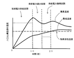
- FIG. 3 is a graph showing an example of the relationship between the temperature of the honeycomb structure and the elapsed time (seconds) of the heating process in the heating process of the embodiment of the heating method of the honeycomb structure of the present invention.
- the horizontal axis indicates the elapsed time (seconds) of the heat generation process
- the vertical axis indicates the temperature of the honeycomb structure part.
- the temperature of the honeycomb structure portion increases upward on the vertical axis.
- the graph shown in FIG. 3 is a graph showing the temperature change of the honeycomb structure portion when electric power is supplied to the honeycomb structure portion like the graph shown in FIG. FIG. 3 shows two temperature changes of the highest temperature and the lowest temperature in the heat generation portion of the honeycomb structure portion.
- the numerical values of power (kW) and time (seconds) shown in FIG. 2 show an example of the heat generation process, and the numerical values of power (kW) and time (seconds) are those of the honeycomb structure of the present embodiment.
- the heat generation process of the heat generation method is not limited.
- a heating process is performed in which power is supplied to the honeycomb structure part 4 of the honeycomb structure 100 to cause the honeycomb structure part 4 to generate heat to a target temperature.
- a honeycomb structure 100 shown in FIG. 1 further includes two electrode portions 21 and 21 disposed on the side surface 5 of the honeycomb structure portion 4.
- wirings 31, 31 are connected to the two electrode portions 21, 21, respectively.
- the wirings 31 and 31 are electrically connected to a power source 30 for supplying power to the honeycomb structure portion 4.
- the electrode part 21 disposed on the side surface 5 of the honeycomb structure part 4 is not limited to the structure shown in FIG. Further, the number of electrode portions 21 arranged on the side surface 5 of the honeycomb structure portion 4 is not limited to two.
- the electrode part 21 may be any one that can supply power to the honeycomb structure part 4 to cause the honeycomb structure part 4 to generate heat.
- the “supplied power reduction section” as described below is performed in such a manner that the minimum temperature at the heat generation portion of the honeycomb structure portion 4 reaches the target temperature described above. It is provided at least once before.
- “Supply power reduction section” refers to a section in which the supply of power to the honeycomb structure portion 4 is stopped or the power supplied to the honeycomb structure portion 4 is reduced. More specifically, in the heating method for the honeycomb structure of the present embodiment, first, the honeycomb structure 4 is heated by supplying power from the power source 30 to the honeycomb structure 4. The “initial power supply period” in FIG. 2 corresponds to this power supply.
- the temperature of the honeycomb structure part rises by generating heat in the honeycomb structure part.
- the supply of power to the honeycomb structure part is stopped for a certain period or the power supplied to the honeycomb structure part is decreased for a certain period (supply) Electricity decrease section).
- this supply power reduction section is provided for the elapsed time of the heat generation process from 10 seconds to 15 seconds.
- the supply of electric power to the honeycomb structure portion is stopped for a certain period in this supply electric power decrease section. That is, in FIG. 2, the power in the supply power decrease section is 0 kW.
- the “target temperature” in the heating method of the honeycomb structure of the present embodiment is a temperature that the honeycomb structure portion 4 should reach when supplying power to the honeycomb structure portion 4 to generate heat as shown in FIG. That is. Therefore, in the heating method for the honeycomb structure according to the present embodiment, the heat is finally generated so that the entire heating portion of the honeycomb structure 4 is equal to or higher than the target temperature described above.
- Such “target temperature” can be appropriately set according to the purpose of use of the honeycomb structure 100. For this reason, there is no restriction
- the target temperature is preferably 100 to 300 ° C., for example.
- the power value in the supply power decrease section only needs to be lower than the power value in the initial power supply period.
- the power supplied to the honeycomb structure portion 4 may be decreased for a certain period in the supply power decrease section.
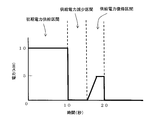
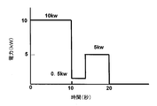
- FIG. 4 shows another example of the relationship between the power (kW) supplied to the honeycomb structure and the elapsed time (seconds) of the heating process in the heating process of the embodiment of the heating method of the honeycomb structure of the present invention. It is a graph which shows.
- FIG. 4 shows an example in which the same electric power as that in the heat generation step shown in FIG. 2 is supplied to the honeycomb structure part except that the electric power in the supply electric power decrease section is changed to 1 kW.
- the honeycomb structure (more specifically, the honeycomb structure portion) can be heated well with less power consumption. That is, in the heating method of the honeycomb structure of the present embodiment, the above-described supply power reduction section is provided at least once before the lowest temperature at the heating portion of the honeycomb structure reaches the target temperature. For this reason, in the supply power decrease section, heat conduction is performed from a portion where the temperature of the honeycomb structure portion is high to a portion where the temperature of the honeycomb structure portion is low, and temperature unevenness in heat generation (in other words, a temperature difference) occurs. Get smaller. For example, as shown in FIG.
- the maximum temperature of the honeycomb structure portion decreases with time, but the minimum temperature of the honeycomb structure portion increases with time. Thereby, the temperature difference of a honeycomb structure part can be made small in the subsequent heat_generation
- the difference between the maximum temperature and the minimum temperature of the honeycomb structure is reduced at the end of the heating process for heating the honeycomb structure to the target temperature. be able to.
- the partial temperature difference of the honeycomb structure is reduced (that is, the minimum temperature is made higher).
- It can be brought close to the maximum temperature).
- the temperature difference at the time when the heat generation process is completed can be reduced, it requires heat generation as compared with the case where heat is generated so that the lowest temperature becomes the same temperature by the conventional method. There is also an effect that less power is required.
- the maximum temperature is lower than in the case where heat is generated so that the minimum temperature becomes the same temperature by the conventional method, the temperature difference of the honeycomb structure can be made smaller as a result.
- the maximum temperature difference between the maximum temperature and the minimum temperature during the heat generation process including the supply power decrease section can be reduced not only at the end of the heat generation process, but at the timing of providing the power supply decrease section. That is, compared with the case where the honeycomb structure is heated by the conventional method, the heating process is provided by providing the supply power decreasing section even when the temperature difference of the heating portion of the honeycomb structure is temporarily increased. It becomes possible to suppress the spread of the temperature difference inside. Therefore, it becomes possible to reduce the maximum temperature difference between the maximum temperature and the minimum temperature during the heat generation process including the supply power decrease section. By reducing the maximum temperature difference during the heat generation process in this way, it becomes difficult for thermal stress due to the temperature difference to occur in the honeycomb structure, and it is possible to suppress breakage such as cracks in the honeycomb structure part. .
- the supply of power and the decrease in power are performed quickly (for example, instantaneously).
- the supply power decreasing section in a state where the maximum temperature at the heating portion of the honeycomb structure is equal to or higher than the target temperature.
- the heat conduction from the high temperature part of a honeycomb structure part to the low temperature part of the said honeycomb structure part will be performed favorably.
- the “part where the temperature of the honeycomb structure part is high” may be referred to as “high-temperature part”.
- the above-mentioned “part where the temperature of the honeycomb structure part is low” may be referred to as “low temperature part”.
- the duration of the supply power decrease section is intended to raise the temperature of the low temperature portion of the honeycomb structure portion by heat conduction from the high temperature portion of the honeycomb structure portion. Therefore, it is preferable that the minimum temperature in the heat generation part of the honeycomb structure portion does not decrease in the supply power decrease section.
- the supply power decrease section when the minimum temperature in the heat generating part of the honeycomb structure portion does not reach the target temperature, it is preferable to provide a supply power return section described later before the minimum temperature decreases. If the duration of the supply power decrease section is short, heat conduction from the high temperature portion to the low temperature portion may not be sufficiently performed. If the duration of the supply power reduction section is too long, it may take too much time for the entire honeycomb structure to reach the target temperature or higher.
- the time until the minimum temperature at the heating portion of the honeycomb structure reaches the target temperature is shorter.
- the “time until the minimum temperature at the heat generation portion of the honeycomb structure reaches the target temperature” means the total elapsed time from the start of the heat generation process. Therefore, the “time until the minimum temperature in the heat generation part of the honeycomb structure portion reaches the target temperature” includes the duration of the “supply power decrease section” described above.
- a temperature equal to or higher than the target temperature is set as the heat generation end temperature, and when the minimum temperature in the heat generation portion of the honeycomb structure part exceeds the heat generation end temperature, Is preferably stopped. That is, it is preferable to end the heat generation process when the minimum temperature in the heat generation portion of the honeycomb structure exceeds the heat generation end temperature.
- the end-of-heat generation temperature is more preferably a target temperature.
- the heating method of the honeycomb structure of the present embodiment in the heating process, after the above-described supply power reduction section, the supply of power to the honeycomb structure part is resumed or the power supplied to the honeycomb structure part is reduced. You may provide the supply electric power return area to increase. That is, in the heating method of the honeycomb structure of the present embodiment, the temperature difference in the heating portion of the honeycomb structure portion is once reduced by the above-described supply power reduction section, and then the heating of the honeycomb structure portion is resumed. Good. Further, when the power is decreased in the supply power decrease section, the power supplied to the honeycomb structure portion may be increased from the reduced state. Further, in the first supply power decrease section, when the heat generation end temperature is exceeded, the supply power return section may not be provided.
- the power value after the supply power return section is 5 kW.
- the minimum temperature and the maximum temperature in the heat generating portion of the honeycomb structure portion rise again. 2 and 3, when the elapsed time from the start of the heat generation process reaches 20 seconds, the minimum temperature at the heat generation portion of the honeycomb structure portion has reached the target temperature, and thus the heat generation process is terminated. That is, the supply of electric power to the honeycomb structure portion is stopped when the above-described elapsed time becomes 20 seconds.
- a second supply power decrease section may be provided after the supply power return section. Further, a second supply power return section may be provided after the second supply power decrease section.
- the supply power return section and the supply power return section may be alternately and repeatedly provided a plurality of times.
- the power values in the second and subsequent supply power reduction sections and the supply power return section may be the same as or different from the power values in the first supply power decrease section and the supply power return section. Good.
- a second supply power reduction section may be provided after the first supply power return section, and then a second supply power return section may be provided.
- FIG. 5 shows still another relationship between the electric power (kW) supplied to the honeycomb structure part and the elapsed time (seconds) of the heating process in the heating process of the embodiment of the heating method of the honeycomb structure of the present invention. It is a graph which shows an example. In FIG. 5, the power in the second supply power return section is 2 kW.
- FIG. 2 the power is instantaneously increased to 5 kW in the supply power return section, but for example, as shown in FIG. 6, the power may be gradually increased in the supply power return section.
- FIG. 6 is a graph showing the relationship between the power (kW) supplied to the honeycomb structure and the elapsed time (seconds) of the heating process in the heating process of the embodiment of the heating method of the honeycomb structure of the present invention. It is a graph which shows another example.
- FIG. 6 shows an example in which the same electric power as that in the heat generation process shown in FIG. 2 is supplied to the honeycomb structure part except that the electric power is gradually increased and increased in the supply electric power return section.
- the type of catalyst supported on the partition walls of the honeycomb structure portion is not particularly limited.
- the catalyst include conventionally known catalysts used for purifying harmful components in exhaust gas.
- the catalyst include an oxidation catalyst, a NOx storage catalyst, and a three-way catalyst.
- the partition wall may support a promoter represented by an oxide of cerium (Ce) or zirconium (Zr), an HC (hydrocarbon) adsorbent, or the like.
- a noble metal such as platinum (Pt), palladium (Pd), rhodium (Rh) can be cited as a suitable example.
- the catalyst may contain cerium and at least one selected from the group consisting of other rare earth metals, alkaline earth metals, and transition metals.
- the rare earth metal for example, samarium (Sm), gadolinium (Gd), neodymium (Nd), yttrium (Y), scandium (Sc), cerium (Ce), lanthanum (La), praseodymium (Pr), etc. Can be mentioned.
- examples of the alkaline earth metal contained in the catalyst include magnesium (Mg), calcium (Ca), strontium (Sr), barium (Ba), and the like.
- transition metal contained in the catalyst examples include manganese (Mn), iron (Fe), cobalt (Co), nickel (Ni), copper (Cu), zinc (Zn), titanium (Ti), zirconium ( Zr), vanadium (V), chromium (Cr) and the like.
- the electric power during the initial power supply period of the heat generation process can be appropriately determined in consideration of the size and material of the honeycomb structure part.
- the power per 1 g of the honeycomb structure part in the initial power supply period is 3.3 to 33.3 W / g. It is preferable. If the power per 1 g of the honeycomb structure portion in the initial power supply period is less than 3.3 W / g, it may be difficult to quickly generate heat in the honeycomb structure portion. On the other hand, when the power per 1 g of the honeycomb structure portion in the initial power supply period exceeds 33.3 W / g, the heat generation unevenness in the carrier becomes large, and cracks are generated due to the thermal stress generated by the heat generation unevenness.
- the power per 1 g of the honeycomb structure portion in the initial power supply period is preferably 3.3 W / g to 33.3 W / g, and more preferably 10 to 23.1 W / g.
- the power in the supply power decrease section of the heat generation process is such that the maximum temperature in the heat generation portion of the honeycomb structure portion decreases in the supply power decrease section.
- the power in the supply power decrease section is more preferably 50% or less of the power in the initial power supply period.
- power supply may be stopped. When the supply of power is stopped, the power in the supply power decrease section is zero (0).
- the power in the supply power decrease section is preferably 50% or less of the power in the initial power supply period, and more preferably 30% or less.
- the power in the supply power return section of the heat generation process takes into account the difference between the ⁇ minimum temperature at the heat generation part '' and the ⁇ heat generation end temperature '' when starting the supply power return section, the elapsed time from the start of the heat generation process, etc. It is preferable to determine appropriately.
- the honeycomb structure portion is heated until the minimum temperature at the heating portion of the honeycomb structure portion becomes 100 ° C. or higher in the heating step. That is, in the heat generation method for the honeycomb structure of the present embodiment, it is preferable to set the heat generation end temperature to 100 ° C. or higher.
- the honeycomb structure portion is heated in the heating step so that the maximum temperature at the heating portion of the honeycomb structure portion does not exceed 1000 ° C. That is, in the initial power supply period and the supply power return section, it is preferable to appropriately provide a supply power decrease section before the maximum temperature at the heat generation portion of the honeycomb structure exceeds 1000 ° C. With this configuration, it is possible to effectively prevent breakage such as cracks in the honeycomb structure.
- the difference between the highest temperature and the lowest temperature in the heating portion of the honeycomb structure portion during the heating process is 900 ° C. or less.
- the difference between the highest temperature and the lowest temperature at the heat generating portion of the honeycomb structure is 600 ° C. or less.
- the difference between the maximum temperature and the minimum temperature is zero (0).
- the method for supplying power to the honeycomb structure There is no particular limitation on the method for supplying power to the honeycomb structure. It is preferable to supply electric power in such a way that the tubular honeycomb structure that generates heat when energized can generate heat more uniformly.
- a power source for supplying power to the honeycomb structure for example, a power converter such as an inverter power source (DC-AC), a DC-DC converter, or an AC-DC converter that can easily control power can be used.
- DC-AC inverter power source
- DC-DC converter DC-DC converter
- AC-DC converter AC-DC converter that can easily control power
- FIG. 7 is a perspective view schematically showing a honeycomb structure used in the heating method of the honeycomb structure of the present invention.
- FIG. 8 is a schematic diagram showing a cross section of the honeycomb structure shown in FIG. 7 parallel to the cell extending direction.
- FIG. 9 is a schematic diagram showing a cross section of the honeycomb structure shown in FIG. 7 orthogonal to the cell extending direction.
- a honeycomb structure 100 shown in FIGS. 7 to 9 includes a porous partition wall 1 and an outer peripheral wall 3 positioned at the outermost periphery, and a tubular honeycomb structure portion 4 that generates heat when energized, and the partition walls of the honeycomb structure portion 4. And a catalyst 7 supported on the catalyst.
- the partition wall 1 partitions and forms a plurality of cells 2 extending from the first end surface 11 to the second end surface 12 serving as a fluid flow path.
- the honeycomb structure 100 further includes two electrode portions 21 and 21 disposed on the side surface 5 of the honeycomb structure portion 4.
- the electrical resistivity of the honeycomb structure portion 4 is preferably 1 to 200 ⁇ cm, and more preferably 40 to 100 ⁇ cm.
- the honeycomb structure portion 4 has an electrical resistivity of 1 to 200 ⁇ cm, even if a current is supplied using a power source having a high voltage, the current does not flow excessively and can be suitably used as a heater.
- the electrical resistivity of the partition wall is a value measured by the four probe method.
- the electrical resistivity of the honeycomb structure part 4 is a value at 400 ° C.
- the porosity of the partition walls is preferably 30 to 60%, and more preferably 30 to 50%.
- the porosity of the partition walls is less than 30%, the partition walls may be deformed when the honeycomb structure is manufactured.
- the porosity exceeds 60%, the strength of the honeycomb structure may be lowered.
- the porosity is a value measured with a mercury porosimeter.
- the average pore diameter of the partition walls is preferably 2 to 15 ⁇ m, and more preferably 4 to 8 ⁇ m. When the average pore diameter of the partition walls is smaller than 2 ⁇ m, the electrical resistivity may become too large. If the average pore diameter is larger than 15 ⁇ m, the electrical resistivity may be too small.
- the average pore diameter is a value measured with a mercury porosimeter.
- the partition wall thickness is preferably 50 to 260 ⁇ m, and more preferably 70 to 180 ⁇ m. When the partition wall thickness is thinner than 50 ⁇ m, the strength of the honeycomb structure may be lowered. If the partition wall thickness is greater than 260 ⁇ m, pressure loss may increase when exhaust gas flows through the honeycomb structure.
- the cell density of the honeycomb structure is preferably 40 to 150 cells / cm 2 , and more preferably 70 to 100 cells / cm 2 .
- the cell density is preferably 40 to 150 cells / cm 2 , and more preferably 70 to 100 cells / cm 2 .
- the material of partition wall 1 and outer peripheral wall 3 is preferably a silicon-silicon carbide composite material or a silicon carbide material as a main component, and is preferably a silicon-silicon carbide composite material or a silicon carbide material. More preferably it is.
- the material of the partition wall 1 and the outer peripheral wall 3 is mainly composed of a silicon-silicon carbide composite material or a silicon carbide material
- the partition wall 1 and the outer peripheral wall 3 are formed of a silicon-silicon carbide composite material or carbonized carbon. It means that 90% by mass or more of the silicon material is contained.
- the electrical resistivity of the honeycomb structure portion can be set to 1 to 200 ⁇ cm.
- the silicon-silicon carbide composite material contains silicon carbide particles as an aggregate and silicon as a binder for bonding the silicon carbide particles, and a plurality of silicon carbide particles are interposed between the silicon carbide particles. It is preferable to be bonded by silicon so as to form pores.
- the silicon carbide material is obtained by sintering silicon carbide particles.
- the “mass of silicon carbide particles” and the “mass of silicon” have the following relationship: Is preferred. That is, the ratio of “mass of silicon” to the total of “mass of silicon carbide particles” and “mass of silicon” is preferably 10 to 40% by mass, and more preferably 15 to 35% by mass. preferable.
- the ratio of the mass of silicon to the total of the mass of silicon carbide particles and the mass of silicon may be referred to as “mass ratio of silicon”.
- the mass ratio of silicon is lower than 10% by mass, the strength of the honeycomb structure may be lowered.
- the shape may not be maintained during firing.
- the above-mentioned “mass of silicon carbide particles” refers to “mass of silicon carbide particles as an aggregate” contained in the partition wall.
- the above-mentioned “mass of silicon” means “mass of silicon as a binder” contained in the partition walls.
- the shape of the cell in the cross section orthogonal to the cell extending direction of the honeycomb structure is a quadrangle, a hexagon, an octagon, or a combination thereof.
- the thickness of the outer peripheral wall constituting the outermost periphery of the honeycomb structure is preferably 0.1 to 1 mm, more preferably 0.2 to 0.8 mm, and particularly preferably 0.2 to 0.5 mm. If the thickness of the outer peripheral wall is less than 0.1 mm, the strength of the honeycomb structure may be lowered. When the thickness of the outer peripheral wall is greater than 1 mm, the area of the partition wall supporting the catalyst may be reduced.
- the porosity of the outer peripheral wall of the honeycomb structure is preferably 35 to 60%, more preferably 35 to 55%, and particularly preferably 35 to 50%.
- the porosity of the outer peripheral wall of the honeycomb structure is within such a range, the thermal shock resistance of the honeycomb structure can be improved. If the porosity of the outer peripheral wall of the honeycomb structure is less than 35%, the effect of improving the thermal shock resistance of the honeycomb structure may be reduced. If the porosity of the outer peripheral wall of the honeycomb structure is larger than 60%, the mechanical strength of the honeycomb structure may be lowered.
- honeycomb structure part There is no particular limitation on the shape of the honeycomb structure part.
- shape of the honeycomb structure portion include a cylindrical shape with a circular bottom surface (cylindrical shape), a cylindrical shape with an oval bottom surface, and a cylindrical shape with a polygonal bottom surface.
- the polygon include a quadrangle, a pentagon, a hexagon, a heptagon, and an octagon.
- the honeycomb structure has a bottom surface area of preferably 2000 to 20000 mm 2 , more preferably 4000 to 10000 mm 2 .
- the length of the honeycomb structure in the central axis direction is preferably 50 to 200 mm, and more preferably 75 to 150 mm.
- the honeycomb structure 100 may further include two electrode portions 21 and 21 disposed on the side surface 5 of the honeycomb structure portion 4.
- each of the two electrode portions 21 and 21 is preferably formed in a strip shape extending in the direction in which the cells 2 of the honeycomb structure portion 4 extend.
- one electrode portion 21 in the two electrode portions 21, 21 has a structure of the honeycomb structure portion 4 with respect to the other electrode portion 21 in the two electrode portions 21, 21. It is preferable to be disposed on the opposite side across the center O.
- the temperature distribution is caused by the length of the distance between the two electrode portions 21 and 21. Bias occurs.
- the heating method of the honeycomb structure of the present embodiment it is possible to further suppress the uneven temperature distribution of the heat generating portion. Note that the number of electrode portions arranged in the honeycomb structure portion and the shape of the electrode portions are not limited to the forms shown in FIGS.
- one electrode portion 21 is disposed on the opposite side of the center O of the honeycomb structure portion 4 with respect to the other electrode portion 21 in the cross section orthogonal to the extending direction of the cells 2”.
- the configuration will be described in detail below.
- a line segment connecting the center point of one electrode portion 21 and the center O of the honeycomb structure portion 4 in a cross section orthogonal to the cell extending direction is referred to as “line segment P”.
- a line segment connecting the center point of the other electrode part 21 and the center O of the honeycomb structure part 4 in a cross section orthogonal to the cell 2 extending direction is referred to as “line segment Q”.
- the center point of one electrode part 21 and the other electrode part 21 is a center point in the circumferential direction of the honeycomb structure part 4.
- the “opposite side across the center O of the honeycomb structure 4” is a positional relationship in which the angle ⁇ formed by the line segment P and the line segment Q is in the range of 170 ° to 190 °. Means. Accordingly, in the above-described configuration, the two electrode portions 21 and 21 are disposed in a positional relationship that satisfies the range of the angle ⁇ . In FIG. 9, the angle ⁇ formed by the line segment P and the line segment Q is 180 °.
- the center angle ⁇ of each of the electrode portions 21 and 21 is 0.5 times (angle ⁇ which is 0.5 times the center angle ⁇ ), The angle is preferably 15 to 65 °, and more preferably 30 to 60 °.
- the “angle ⁇ which is 0.5 times the central angle ⁇ ” of one electrode portion 21 is 0.8 to 0.8 with respect to the “angle ⁇ which is 0.5 times the central angle ⁇ ” of the other electrode portion 21
- the size is preferably 1.2 times, and more preferably 1.0 times the size (the same size).
- the electrode part 21 of the honeycomb structure 100 has a shape in which a planar rectangular member is curved along a cylindrical outer periphery.
- the shape when the curved electrode portion 21 is deformed so as to be a flat member that is not curved is referred to as a “planar shape” of the electrode portion 21.
- the “planar shape” of the electrode portion 21 shown in FIGS. 7 to 9 is a rectangle.
- the outer peripheral shape of the electrode part means “the outer peripheral shape in the planar shape of the electrode part”.
- the outer peripheral shape of the strip-shaped electrode portion 21 may be a shape in which rectangular corners are formed in a curved shape. Moreover, the outer peripheral shape of the strip-shaped electrode part 21 may be a shape in which rectangular corners are chamfered linearly. The curved shape and chamfering described above in the outer peripheral shape of the strip-shaped electrode portion 21 may be used in combination in one electrode portion.
- the electrical resistivity of the electrode portion 21 is preferably 0.1 to 100 ⁇ cm, and more preferably 0.1 to 50 ⁇ cm.
- the two electrode portions 21 and 21 effectively serve as electrodes in the pipe through which high-temperature exhaust gas flows.
- the electrical resistivity of the electrode part 21 is smaller than 0.1 ⁇ cm, the temperature of the honeycomb structure part near both ends of the electrode part 21 may easily rise in a cross section orthogonal to the cell extending direction. If the electrical resistivity of the electrode portion 21 is larger than 100 ⁇ cm, it may be difficult to play a role as an electrode because current hardly flows.
- the electrical resistivity of the electrode part is a value at 400 ° C.
- the electrode portion 21 is preferably composed mainly of a silicon-silicon carbide composite material or a silicon carbide material, and more preferably a silicon-silicon carbide composite material or a silicon carbide material.
- the electrode portion 21 is particularly preferably formed using silicon carbide particles and silicon as raw materials, except for impurities that are usually contained. As described above, when the electrode portion 21 has “silicon-silicon carbide composite material or silicon carbide material” as a main component, the component of the electrode portion 21 and the component of the honeycomb structure portion 4 are the same or close components. For this reason, the thermal expansion coefficient of the electrode part 21 and the honeycomb structure part 4 becomes the same value or a close value.
- the bonding strength between the electrode part 21 and the honeycomb structure part 4 is also increased. Therefore, even when thermal stress is applied to the honeycomb structure, it is possible to prevent the electrode portion 21 from being peeled off from the honeycomb structure portion 4 and the joint portion between the electrode portion 21 and the honeycomb structure portion 4 being damaged.
- the electrode part 21 preferably has an average pore diameter of 5 to 45 ⁇ m, more preferably 7 to 40 ⁇ m.
- the average pore diameter of the electrode part 21 is in such a range, a suitable electrical resistivity can be obtained. If the average pore diameter of the electrode part 21 is smaller than 5 ⁇ m, the electrical resistivity may be too high. When the average pore diameter of the electrode portion 21 is larger than 45 ⁇ m, the strength of the electrode portion 21 is weakened and may be easily damaged.
- the average pore diameter is a value measured with a mercury porosimeter.
- the electrical resistivity of the electrode portion 21 is lower than the electrical resistivity of the honeycomb structure portion 4. Furthermore, the electrical resistivity of the electrode portion 21 is more preferably 20% or less, and particularly preferably 1 to 10% of the electrical resistivity of the honeycomb structure portion 4. By setting the electrical resistivity of the electrode part 21 to 20% or less of the electrical resistivity of the honeycomb structure part 4, the electrode part 21 functions more effectively as an electrode.
- the electrode portion may further be provided with a connection portion for connecting a wiring from the power source. By constituting in this way, it becomes easier to supply power to the honeycomb structure.
- the isostatic strength of the honeycomb structure 100 is preferably 1 MPa or more, and more preferably 3 MPa or more.
- the isostatic strength is preferably as large as possible. However, considering the material, structure, etc. of the honeycomb structure 100, the upper limit is about 6 MPa. If the isostatic strength is less than 1 MPa, the honeycomb structure may be easily damaged. Isostatic strength is a value measured by applying hydrostatic pressure in water.
- the type of catalyst supported on the partition walls of the honeycomb structure There is no particular limitation on the type of catalyst supported on the partition walls of the honeycomb structure.
- the catalyst include conventionally known catalysts used for purifying harmful components in exhaust gas.
- the catalyst include an oxidation catalyst, a NOx storage catalyst, and a three-way catalyst.
- the partition wall may support a promoter represented by an oxide of cerium (Ce) or zirconium (Zr), an HC (hydrocarbon) adsorbent, or the like.
- the amount of catalyst supported on the partition walls There is no particular limitation on the amount of catalyst supported on the partition walls.
- the mass (g) of the catalyst supported per volume 1 L (1 liter) of the honeycomb structure part may be referred to as “supported amount (g / L)”.
- the supported amount of the catalyst can be appropriately set according to the type of the catalyst and the amount of harmful components in the exhaust gas to be purified.
- Example 1 First, a porous partition wall that defines a plurality of cells, a cylindrical honeycomb structure part that has an outer peripheral wall located at the outermost periphery and generates heat when energized, and a catalyst carried on the partition wall of the honeycomb structure part, A honeycomb structure provided with was prepared. In Example 1, electric power was supplied to the honeycomb structure portion of the honeycomb structure to cause the honeycomb structure to generate heat.
- the honeycomb structure is configured as follows.
- the honeycomb structure had a partition wall thickness of about 100 ⁇ m and a cell density of 600 cells / cm 2 .
- the bottom surface of the honeycomb structure was a circle having a diameter of 93 mm, and the length of the honeycomb structure in the cell extending direction was 100 mm.
- the porosity of the honeycomb structure was 48%.
- the porosity is a value measured by a mercury porosimeter (manufactured by Micromeritics, Autopore IV9505).
- the material of the partition walls and the outer peripheral wall was mainly composed of a silicon-silicon carbide composite material.
- the electrical resistivity of the honeycomb structure part was 30 ⁇ cm.
- the electrode part was produced using the raw material which has silicon carbide particle
- the electrode part forming raw material was applied in a strip shape on the side surface of the honeycomb structure part so that the thickness (thickness after drying and firing) was 1.0 mm.
- the electrode part forming raw material was applied to two sides of the honeycomb structure part. And in the cross section orthogonal to the cell extending direction, one of the portions where the electrode part forming raw material is applied is arranged on the opposite side across the center of the honeycomb structure part with respect to the other. did.
- the shape (peripheral shape) of the electrode part forming raw material applied to the side surface of the honeycomb structure part was a rectangle.
- the electrode part forming raw material was applied to the side surface of the honeycomb structure part so that the coating film made of the electrode part forming raw material extends between both ends of the honeycomb structure part.
- the electrode part was produced by drying and firing the electrode part forming raw material applied to the honeycomb structure part.
- the electrical resistivity of the electrode part was 1 ⁇ cm.
- Example 1 a three-way catalyst was supported on the partition walls of the honeycomb structure.
- the amount of catalyst supported was 150 g / L.
- the catalyst activation temperature of this catalyst is 300 ° C.
- the target temperature when heating the honeycomb structure portion was set to 300 ° C.
- the two electrode parts of such a honeycomb structure and a DC power source were electrically connected by wiring, power was supplied to the honeycomb structure, and the honeycomb structure was heated by Joule heat.
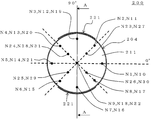
- FIGS. 16A and 16B show measurement points (N1 to N31) at which the temperature of the honeycomb structure portion 204 of the honeycomb structure 200 was measured.
- FIG. 16A is an explanatory diagram for explaining the measurement points of the honeycomb structure in the example, and is a plan view on the first end face side of the honeycomb structure.
- FIG. 16B is a cross-sectional view showing the AA cross section of FIG. 16A.
- measurement points N1 to N31 for measuring the temperature of the honeycomb structure portion 204 of the honeycomb structure 200 will be described with reference to FIGS. 16A and 16B.
- the measurement point on the broken line indicating 0 ° on the first end surface 211 side of the honeycomb structure portion 204 is set as the measurement point N1
- the measurement point at a position moved 45 ° counterclockwise is set as the measurement point N2
- a measurement point at a position moved 45 ° counterclockwise was defined as a measurement point N3.
- the measurement points are provided in 45 ° increments counterclockwise, and further, the measurement points are respectively provided at both end portions and the intermediate portion in the direction from the first end surface 211 to the second end surface 212 of the honeycomb structure portion 204.
- reference numeral 221 denotes an electrode portion.
- FIG. 10 is a graph showing the relationship between the temperature (° C.) of the honeycomb structure portion and the elapsed time (seconds) of the heating process in the heating process of the heating method of the honeycomb structure of Example 1.
- FIG. 11 is a graph showing the relationship between the electric power (kW) supplied to the honeycomb structure portion and the elapsed time (seconds) of the heating process in the heating process of the heating method of the honeycomb structure of Example 1.
- the power supplied to the honeycomb structure portion was 10 kW for 10 seconds from the start of power supply.
- 10 seconds from the start of power supply is defined as an “initial power supply period”.
- the time when the power supply is started is defined as the start time of the heat generation process.
- the minimum temperature in the heat generation portion of the honeycomb structure portion at the time when 10 seconds passed from the start time of the heat generation step was about 180 ° C.
- the maximum temperature in the heat generation portion of the honeycomb structure portion at the time when 10 seconds passed from the start time of the heat generation step was about 580 ° C.
- a "Supply power decrease period” was provided for 5 seconds. That is, the power supply to the honeycomb structure was stopped for 10 to 15 seconds, calculated from the start time of the heat generation process.
- the maximum temperature in the heat generation portion of the honeycomb structure portion decreased.
- the minimum temperature in the heat generation portion of the honeycomb structure portion increased. The increase in the minimum temperature in the heat generation part of the honeycomb structure part is due to the provision of the “supply power reduction section”, whereby the temperature becomes uniform due to heat conduction from the high temperature part.
- the minimum temperature in the heat generation portion of the honeycomb structure portion at the time when 15 seconds passed from the start time of the heat generation step was about 260 ° C. Further, the maximum temperature in the heat generation portion of the honeycomb structure portion at the time when 15 seconds had elapsed from the start time of the heat generation step was about 525 ° C.
- a “Supply power return section” was provided for 5 seconds. That is, the supply of power to the honeycomb structure portion was resumed from 15 seconds to 20 seconds, calculated from the start time of the heat generation process. In the “supply power return section”, 5 kW of power was supplied to the honeycomb structure. At the time when 20 seconds passed from the start time of the heat generation step, the minimum temperature in the heat generation portion of the honeycomb structure portion exceeded 300 ° C., and thus the power supply to the honeycomb structure portion was stopped. This “time when supply of power to the honeycomb structure portion is stopped” is defined as “at the end of the heat generation process”.
- heating process continuation section includes the “supply power return section”.
- the minimum temperature at the end of the heat generation process in the heat generation portion of the honeycomb structure portion was 302 ° C.
- the amount of electric power supplied to the honeycomb structure portion in the heating process continuing section was 12.5 kW seconds.
- the maximum difference (hereinafter referred to as “maximum temperature difference”) between the highest temperature and the lowest temperature in the heat generation portion of the honeycomb structure portion in the heat generation process continuing section was 381 ° C.
- the maximum temperature in the heat generation part of the honeycomb structure part in the heat generation process continuing section was 596 ° C.
- the total time (second) of the heat generation process, the amount of power supplied to the honeycomb structure part (kW second), the maximum temperature (° C.), the maximum temperature difference (° C.), The minimum temperature (° C.) at the end is shown in Table 1.
- the honeycomb structure after 20 seconds from the start time of the heat generation process was evaluated as to whether the minimum temperature in the heat generation portion of the honeycomb structure portion exceeded the target temperature (that is, 300 ° C.).
- the evaluation results are shown in the column “Target Temperature” in Table 1.
- the minimum temperature in the heat generation portion of the honeycomb structure part after 20 seconds from the start time of the heat generation process (that is, at the end of the heat generation process) is equal to or higher than the target temperature is referred to as “pass”. To do.
- the case where the lowest temperature in the heat generation portion of the honeycomb structure portion after 20 seconds from the start time of the heat generation process (that is, at the end of the heat generation process) is lower than the target temperature is determined to be “failed”.
- the honeycomb structure was evaluated for the presence of cracks.
- the evaluation results are shown in the “crack” column in Table 1.
- the presence or absence of cracks was determined by a visual inspection method using a microscope. The case where there is no crack is set as “pass”, and the case where there is a crack is set as “fail”.
- Example 2 In Example 2, as shown in FIGS. 12 and 13, the power supplied to the honeycomb structure portion was 10 kW for 10 seconds from the start of power supply. Thereafter, the power was set to 0.5 kW for 3 seconds, and then the power was increased to 5 kW for 7 seconds.
- FIG. 12 is a graph showing the relationship between the temperature (° C.) of the honeycomb structure portion and the elapsed time (seconds) of the heating process in the heating process of the heating method of the honeycomb structure of Example 2.
- FIG. 13 is a graph showing the relationship between the power (kW) supplied to the honeycomb structure and the elapsed time (seconds) of the heating process in the heating process of the heating method of the honeycomb structure of Example 2.
- the amount of electric power supplied to the honeycomb structure part is 13.7 kW seconds.
- the total time (second) of the heat generation process, the amount of power supplied to the honeycomb structure (kW second), the maximum temperature (° C.), the maximum temperature difference (° C.), The minimum temperature (° C.) at the end is shown in Table 1.
- Example 2 the honeycomb structure at the end of the heat generation process was evaluated as to whether the minimum temperature in the heat generation portion of the honeycomb structure exceeded the target temperature. Moreover, the presence or absence of generation
- Comparative Example 1 In Comparative Example 1, as shown in FIG. 14 and FIG. 15, 6.25 kW of electric power was supplied to the honeycomb structure portion for 20 seconds to cause the honeycomb structure portion to generate heat.
- the honeycomb structure used is the same as the honeycomb structure used in Example 1.
- FIG. 14 is a graph showing the relationship between the temperature (° C.) of the honeycomb structure portion and the elapsed time (seconds) of the heating process in the heating process of the heating method of the honeycomb structure of Comparative Example 1.
- FIG. 15 is a graph showing the relationship between the electric power (kW) supplied to the honeycomb structure and the elapsed time (seconds) of the heating process in the heating process of the heating method of the honeycomb structure of Comparative Example 1.
- Comparative Example 2 In Comparative Example 2, power of 6.85 kW seconds was supplied to the honeycomb structure portion for 20 seconds to cause the honeycomb structure portion to generate heat.
- the honeycomb structure used is the same as the honeycomb structure used in Example 1.
- the heat generation Table 1 shows the minimum temperature (° C.) at the end of the process.
- the honeycomb structure at the end of the heat generation process was evaluated as to whether the minimum temperature in the heat generation portion of the honeycomb structure exceeded the target temperature.
- the honeycomb structure was also evaluated for the presence or absence of cracks in the same manner as in Example 1. The evaluation results are shown in Table 1.
- the heating method of the honeycomb structure of Example 1 and the heating method of the honeycomb structure of Comparative Example 1 are the amount of electric power (kW second) supplied to the honeycomb structure portion between the start time of the heating process and 20 seconds. ) Is the same.
- the maximum temperature difference in the heat generation process continuation section is larger than that in Comparative Example 1, the occurrence of cracks occurred.
- the honeycomb structure could be heated to the target temperature.
- Comparative Example 1 the minimum temperature at the end of the heat generation process did not reach the target temperature, although the total time and power amount of the heat generation process were the same as in Example 1.
- Example 1 in the heating method for the honeycomb structure of Comparative Example 1, more power is required than in Example 1 in order to reach the minimum temperature of the honeycomb structure to 300 ° C., which is the current target temperature. As described above, it was found that the heating method for the honeycomb structure of Example 1 can reach the target temperature to the target temperature in a shorter time and with less power.
- the heating method of the honeycomb structure of Example 2 and the heating method of the honeycomb structure of Comparative Example 2 are the amount of electric power supplied to the honeycomb structure portion between the start time of the heating process and 20 seconds ( kW second) is the same.
- the amount of power supplied to the honeycomb structure part was larger than the amount of power in Comparative Example 1, so that the lowest temperature at the end of the heat generation process reached the target temperature.
- the maximum temperature difference in the exothermic process continuing section became very large, and cracks occurred in the honeycomb structure.
- the heating method of the honeycomb structure of Example 2 as in Example 1, since the supply power decrease section is provided 10 seconds after the start time of the heating process, the maximum temperature difference in the heating process continuation section is reduced. We were able to. For this reason, in the heating method of the honeycomb structure of Example 2, the honeycomb structure could be heated to the target temperature in a state where no crack was generated.
- the heating method for a honeycomb structure of the present invention can be used as a method for generating heat up to a predetermined temperature in a honeycomb structure used in an exhaust gas purifying apparatus for purifying exhaust gas of an automobile.
- partition wall 1: partition wall, 2: cell, 3: outer peripheral wall, 4,204: honeycomb structure part, 5: side surface, 7: catalyst, 11, 211: first end surface, 12, 212: second end surface, 21, 221: electrode Part, 30: power supply, 31: wiring, 100, 200: honeycomb structure, O: center, P, Q: line segment, ⁇ : center angle, ⁇ : angle formed by line segment and line segment, ⁇ : 0.5 times the center angle.
Landscapes
- Engineering & Computer Science (AREA)
- Chemical & Material Sciences (AREA)
- Combustion & Propulsion (AREA)
- Mechanical Engineering (AREA)
- General Engineering & Computer Science (AREA)
- Chemical Kinetics & Catalysis (AREA)
- Health & Medical Sciences (AREA)
- Toxicology (AREA)
- Exhaust Gas After Treatment (AREA)
- Catalysts (AREA)
- Exhaust Gas Treatment By Means Of Catalyst (AREA)
Description
本発明のハニカム構造体の発熱方法の一の実施形態は、図1に示すようなハニカム構造体100を用いて行われる、ハニカム構造体の発熱方法である。図1に示すハニカム構造体100は、通電により発熱する筒状のハニカム構造部4と、ハニカム構造部4の隔壁1に担持された触媒7と、を備えたものである。ハニカム構造部4は、多孔質の隔壁1、及び最外周に位置する外周壁3を有するものである。多孔質の隔壁1により、流体の流路となる一方の端面である第一端面11から他方の端面である第二端面12まで延びる複数のセル2が区画形成されている。
次に、本実施形態のハニカム構造体の発熱方法に用いられるハニカム構造体について説明する。本実施形態のハニカム構造体の発熱方法に用いられるハニカム構造体としては、例えば、図7~図9に示すハニカム構造体を挙げることができる。図7は、本発明のハニカム構造体の発熱方法に用いられるハニカム構造体を模式的に示す斜視図である。図8は、図7に示すハニカム構造体の、セルの延びる方向に平行な断面を示す模式図である。図9は、図7に示すハニカム構造体の、セルの延びる方向に直交する断面を示す模式図である。
まず、複数のセルを区画形成する多孔質の隔壁、及び最外周に位置する外周壁を有し、通電により発熱する筒状のハニカム構造部と、ハニカム構造部の隔壁に担持された触媒と、を備えたハニカム構造体を用意した。実施例1においては、このハニカム構造体のハニカム構造部に電力を供給して、ハニカム構造体を発熱させた。

実施例2においては、図12及び図13に示すように、電力の供給開始から10秒間、ハニカム構造部に供給する電力を10kWとした。その後、3秒間、電力を0.5kWとし、その後、7秒間、電力を5kWに増加した。図12は、実施例2のハニカム構造体の発熱方法の発熱工程における、ハニカム構造部の温度(℃)と、発熱工程の経過時間(秒)との関係を示すグラフである。図13は、実施例2のハニカム構造体の発熱方法の発熱工程における、ハニカム構造部に供給する電力(kW)と、発熱工程の経過時間(秒)との関係を示すグラフである。実施例2のハニカム構造体の発熱方法においては、ハニカム構造部に供給した電力量が13.7kW秒である。実施例2のハニカム構造体の発熱方法における、発熱工程の総時間(秒)、ハニカム構造部に供給した電力量(kW秒)、最高温度(℃)、最大温度差(℃)、発熱工程の終了時の最低温度(℃)を表1に示す。
比較例1においては、図14及び図15に示すように、ハニカム構造部に、6.25kWの電力を20秒間供給して、ハニカム構造部を発熱させた。使用したハニカム構造体は、実施例1に使用したハニカム構造体と同様のものである。図14は、比較例1のハニカム構造体の発熱方法の発熱工程における、ハニカム構造部の温度(℃)と、発熱工程の経過時間(秒)との関係を示すグラフである。図15は、比較例1のハニカム構造体の発熱方法の発熱工程における、ハニカム構造部に供給する電力(kW)と、発熱工程の経過時間(秒)との関係を示すグラフである。
比較例2においては、ハニカム構造部に、6.85kW秒の電力を20秒間供給して、ハニカム構造部を発熱させた。使用したハニカム構造体は、実施例1に使用したハニカム構造体と同様のものである。
実施例1のハニカム構造体の発熱方法と、比較例1のハニカム構造体の発熱方法とは、発熱工程の開始時間から20秒までの間に、ハニカム構造部に供給された電力量(kW秒)が同じである。図10、及び図12に示すように、供給電力減少区間を設けた実施例1においては、発熱工程継続区間の最大温度差が、比較例1の場合と比較して大きいものの、クラックの発生が無い状態で、ハニカム構造体を目標温度まで発熱させることができた。一方、比較例1においては、実施例1と発熱工程の総時間及び電力量が同じであるにも関わらず、発熱工程の終了時の最低温度が、目標温度に到達しなかった。即ち、比較例1のハニカム構造体の発熱方法では、ハニカム構造体の最低温度を、今回の目標温度である300℃まで到達させるために、実施例1よりも多くの電力が必要になる。このように、実施例1のハニカム構造体の発熱方法は、結果的に、より短時間で且つ少ない電力で、ハニカム構造体を目標温度に到達させることが可能であることが分かった。
Claims (8)
- 流体の流路となる第一端面から第二端面まで延びる複数のセルを区画形成する多孔質の隔壁、及び最外周に位置する外周壁を有し、通電により発熱する筒状のハニカム構造部と、前記ハニカム構造部の前記隔壁に担持された触媒と、を備えたハニカム構造体の前記ハニカム構造部に電力を供給して、前記ハニカム構造部を目標温度まで発熱させる発熱工程を備え、
前記発熱工程において、前記ハニカム構造部の発熱部位における最低温度が前記目標温度に到達する前に、前記ハニカム構造部への電力の供給を停止する又は前記ハニカム構造部に供給する電力を減少させる供給電力減少区間を、少なくとも1回設けるハニカム構造体の発熱方法。 - 前記発熱工程において、前記供給電力減少区間の後に、前記ハニカム構造部への電力の供給を再開する又は前記ハニカム構造部に供給する電力を減少させた状態から増加させる供給電力復帰区間を設ける請求項1に記載のハニカム構造体の発熱方法。
- 前記発熱工程において、前記ハニカム構造部を、前記ハニカム構造部の発熱部位における最低温度が100℃以上になるまで発熱させる請求項1又は2に記載のハニカム構造体の発熱方法。
- 前記発熱工程において、前記ハニカム構造部を、前記ハニカム構造部の発熱部位における最高温度が1000℃を超えないように発熱させる請求項1~3のいずれか一項に記載のハニカム構造体の発熱方法。
- 前記発熱工程中の、前記ハニカム構造部の発熱部位における最高温度と最低温度との差が、900℃以下である請求項1~4のいずれか一項に記載のハニカム構造体の発熱方法。
- 前記ハニカム構造体は、前記ハニカム構造部の側面に配設された2つ以上の電極部を更に備えたものである請求項1~5のいずれか一項に記載のハニカム構造体の発熱方法。
- 前記発熱工程において、少なくとも前記ハニカム構造部の発熱部位における最高温度が、前記目標温度以上の温度となった状態で、前記供給電力減少区間を設ける請求項1~6のいずれか一項に記載のハニカム構造体の発熱方法。
- 前記供給電力減少区間中において、前記ハニカム構造部の発熱部位における最高温度が時間経過とともに減少する請求項1~7のいずれか一項に記載のハニカム構造体の発熱方法。
Priority Applications (4)
| Application Number | Priority Date | Filing Date | Title |
|---|---|---|---|
| CN201380028389.4A CN104395576B (zh) | 2012-03-30 | 2013-03-29 | 蜂窝结构体的发热方法 |
| EP13770336.9A EP2832964B1 (en) | 2012-03-30 | 2013-03-29 | Heating method of honeycomb structure |
| JP2014508241A JP6101249B2 (ja) | 2012-03-30 | 2013-03-29 | ハニカム構造体の発熱方法 |
| US14/496,618 US9820337B2 (en) | 2012-03-30 | 2014-09-25 | Heating method of honeycomb structure |
Applications Claiming Priority (2)
| Application Number | Priority Date | Filing Date | Title |
|---|---|---|---|
| JP2012-083099 | 2012-03-30 | ||
| JP2012083099 | 2012-03-30 |
Related Child Applications (1)
| Application Number | Title | Priority Date | Filing Date |
|---|---|---|---|
| US14/496,618 Continuation US9820337B2 (en) | 2012-03-30 | 2014-09-25 | Heating method of honeycomb structure |
Publications (1)
| Publication Number | Publication Date |
|---|---|
| WO2013147273A1 true WO2013147273A1 (ja) | 2013-10-03 |
Family
ID=49260511
Family Applications (1)
| Application Number | Title | Priority Date | Filing Date |
|---|---|---|---|
| PCT/JP2013/059774 Ceased WO2013147273A1 (ja) | 2012-03-30 | 2013-03-29 | ハニカム構造体の発熱方法 |
Country Status (5)
| Country | Link |
|---|---|
| US (1) | US9820337B2 (ja) |
| EP (1) | EP2832964B1 (ja) |
| JP (1) | JP6101249B2 (ja) |
| CN (1) | CN104395576B (ja) |
| WO (1) | WO2013147273A1 (ja) |
Cited By (4)
| Publication number | Priority date | Publication date | Assignee | Title |
|---|---|---|---|---|
| JP2015183587A (ja) * | 2014-03-24 | 2015-10-22 | 日立建機株式会社 | 熱機関の排ガス浄化装置、排ガス浄化方法及び排ガス浄化触媒 |
| JP2018096209A (ja) * | 2016-12-08 | 2018-06-21 | トヨタ自動車株式会社 | 内燃機関の排気浄化装置 |
| JP2020502429A (ja) * | 2016-10-24 | 2020-01-23 | ビーエーエスエフ コーポレーション | NOx削減のための一体化SCR触媒およびLNT |
| JPWO2023062733A1 (ja) * | 2021-10-13 | 2023-04-20 |
Families Citing this family (5)
| Publication number | Priority date | Publication date | Assignee | Title |
|---|---|---|---|---|
| JP6581926B2 (ja) | 2016-03-07 | 2019-09-25 | 日本碍子株式会社 | ハニカム構造体 |
| JP6626377B2 (ja) * | 2016-03-14 | 2019-12-25 | 日本碍子株式会社 | ハニカム型加熱装置並びにその使用方法及び製造方法 |
| JP7038585B2 (ja) * | 2018-03-30 | 2022-03-18 | 日本碍子株式会社 | セラミックス多孔体及び集塵用フィルタ |
| JP2020081922A (ja) * | 2018-11-16 | 2020-06-04 | 日本碍子株式会社 | 電気加熱型触媒用担体及び排ガス浄化装置 |
| DE102022206430A1 (de) * | 2021-06-29 | 2022-12-29 | Cummins Emission Solutions Inc. | Systeme und Verfahren zur Reduzierung der NOx-Emissionen von Nachbehandlungssystemen |
Citations (8)
| Publication number | Priority date | Publication date | Assignee | Title |
|---|---|---|---|---|
| JPH08141408A (ja) | 1994-11-24 | 1996-06-04 | Nippon Soken Inc | 排ガス浄化用抵抗調整型ヒータ付触媒担体およびその製造方法 |
| JPH0979029A (ja) * | 1995-09-13 | 1997-03-25 | Toyota Motor Corp | 電気加熱式触媒の制御装置 |
| JP2931362B2 (ja) | 1990-04-12 | 1999-08-09 | 日本碍子株式会社 | 抵抗調節型ヒーター及び触媒コンバーター |
| JP4136319B2 (ja) | 2000-04-14 | 2008-08-20 | 日本碍子株式会社 | ハニカム構造体及びその製造方法 |
| JP2010229978A (ja) * | 2009-03-30 | 2010-10-14 | Ngk Insulators Ltd | 通電加熱型ハニカム体の制御システム |
| WO2011125817A1 (ja) | 2010-03-31 | 2011-10-13 | 日本碍子株式会社 | ハニカム構造体 |
| JP2011231708A (ja) * | 2010-04-28 | 2011-11-17 | Denso Corp | 触媒温度状態診断装置 |
| JP2012163058A (ja) * | 2011-02-08 | 2012-08-30 | Toyota Motor Corp | 触媒コンバータ装置及び触媒担体通電方法 |
Family Cites Families (12)
| Publication number | Priority date | Publication date | Assignee | Title |
|---|---|---|---|---|
| US4415800A (en) * | 1981-08-24 | 1983-11-15 | International Business Machines Corporation | Method and apparatus for monitoring and controlling heated fusers for copiers |
| JPH04235583A (ja) * | 1991-01-11 | 1992-08-24 | Toshiba Corp | 温度制御装置 |
| US5288975A (en) | 1991-01-30 | 1994-02-22 | Ngk Insulators, Ltd. | Resistance adjusting type heater |
| US5444978A (en) * | 1993-03-15 | 1995-08-29 | Toyota Jidosha Kabushiki Kaisha | Catalyst warming up device of an internal combustion engine |
| DE69620290T2 (de) * | 1995-05-19 | 2002-11-28 | Sharp K.K., Osaka | Tonerbildfixiervorrichtung für Bilderzeugungsgerät |
| US5845492A (en) * | 1995-09-18 | 1998-12-08 | Nippondenso Co., Ltd. | Internal combustion engine control with fast exhaust catalyst warm-up |
| JP3322098B2 (ja) * | 1995-11-06 | 2002-09-09 | トヨタ自動車株式会社 | 内燃機関の排気浄化装置 |
| JPH09228868A (ja) * | 1996-02-22 | 1997-09-02 | Honda Motor Co Ltd | 内燃エンジンの吸入空気量制御装置 |
| SE516288C2 (sv) * | 1996-07-09 | 2001-12-10 | Kongsberg Automotive Ab | Förfarande vid uppvärmning av ett säte |
| US6114671A (en) * | 1999-07-22 | 2000-09-05 | Trw Inc. | System for and method of controlling the temperature of an object using temperature control elements spaced from the object |
| JP3800118B2 (ja) * | 2002-03-27 | 2006-07-26 | ブラザー工業株式会社 | 熱定着装置および画像形成装置 |
| CN1680689A (zh) * | 2004-04-08 | 2005-10-12 | 中国环境科学研究院 | 用于内燃机排气净化装置的电加热器 |
-
2013
- 2013-03-29 EP EP13770336.9A patent/EP2832964B1/en not_active Not-in-force
- 2013-03-29 CN CN201380028389.4A patent/CN104395576B/zh active Active
- 2013-03-29 JP JP2014508241A patent/JP6101249B2/ja not_active Expired - Fee Related
- 2013-03-29 WO PCT/JP2013/059774 patent/WO2013147273A1/ja not_active Ceased
-
2014
- 2014-09-25 US US14/496,618 patent/US9820337B2/en not_active Expired - Fee Related
Patent Citations (8)
| Publication number | Priority date | Publication date | Assignee | Title |
|---|---|---|---|---|
| JP2931362B2 (ja) | 1990-04-12 | 1999-08-09 | 日本碍子株式会社 | 抵抗調節型ヒーター及び触媒コンバーター |
| JPH08141408A (ja) | 1994-11-24 | 1996-06-04 | Nippon Soken Inc | 排ガス浄化用抵抗調整型ヒータ付触媒担体およびその製造方法 |
| JPH0979029A (ja) * | 1995-09-13 | 1997-03-25 | Toyota Motor Corp | 電気加熱式触媒の制御装置 |
| JP4136319B2 (ja) | 2000-04-14 | 2008-08-20 | 日本碍子株式会社 | ハニカム構造体及びその製造方法 |
| JP2010229978A (ja) * | 2009-03-30 | 2010-10-14 | Ngk Insulators Ltd | 通電加熱型ハニカム体の制御システム |
| WO2011125817A1 (ja) | 2010-03-31 | 2011-10-13 | 日本碍子株式会社 | ハニカム構造体 |
| JP2011231708A (ja) * | 2010-04-28 | 2011-11-17 | Denso Corp | 触媒温度状態診断装置 |
| JP2012163058A (ja) * | 2011-02-08 | 2012-08-30 | Toyota Motor Corp | 触媒コンバータ装置及び触媒担体通電方法 |
Non-Patent Citations (1)
| Title |
|---|
| See also references of EP2832964A4 |
Cited By (6)
| Publication number | Priority date | Publication date | Assignee | Title |
|---|---|---|---|---|
| JP2015183587A (ja) * | 2014-03-24 | 2015-10-22 | 日立建機株式会社 | 熱機関の排ガス浄化装置、排ガス浄化方法及び排ガス浄化触媒 |
| JP2020502429A (ja) * | 2016-10-24 | 2020-01-23 | ビーエーエスエフ コーポレーション | NOx削減のための一体化SCR触媒およびLNT |
| JP7408392B2 (ja) | 2016-10-24 | 2024-01-05 | ビーエーエスエフ コーポレーション | NOx削減のための一体化SCR触媒およびLNT |
| JP2018096209A (ja) * | 2016-12-08 | 2018-06-21 | トヨタ自動車株式会社 | 内燃機関の排気浄化装置 |
| JPWO2023062733A1 (ja) * | 2021-10-13 | 2023-04-20 | ||
| JP7622866B2 (ja) | 2021-10-13 | 2025-01-28 | 株式会社オートネットワーク技術研究所 | 車載用制御装置 |
Also Published As
| Publication number | Publication date |
|---|---|
| JPWO2013147273A1 (ja) | 2015-12-14 |
| US9820337B2 (en) | 2017-11-14 |
| US20150014292A1 (en) | 2015-01-15 |
| JP6101249B2 (ja) | 2017-03-22 |
| EP2832964B1 (en) | 2017-07-19 |
| EP2832964A4 (en) | 2015-08-19 |
| CN104395576B (zh) | 2017-07-18 |
| EP2832964A1 (en) | 2015-02-04 |
| CN104395576A (zh) | 2015-03-04 |
Similar Documents
| Publication | Publication Date | Title |
|---|---|---|
| JP6101249B2 (ja) | ハニカム構造体の発熱方法 | |
| JP5261256B2 (ja) | 通電発熱用ハニカム体及びその製造方法 | |
| JP6438939B2 (ja) | ハニカム構造体 | |
| EP2181755A2 (en) | Honeycomb structure and reactor using honeycomb structure | |
| JP5027732B2 (ja) | プラズマ処理装置 | |
| JP5064445B2 (ja) | プラズマリアクタ | |
| JP5649889B2 (ja) | 排気ガス浄化装置 | |
| CN111691952B (zh) | 电加热型载体、废气净化装置以及电加热型载体的制造方法 | |
| WO2016133087A1 (ja) | 排ガス浄化用触媒 | |
| JPH06285337A (ja) | ハニカムヒーター | |
| US12523167B2 (en) | Honeycomb structure, exhaust gas purifying device and method for producing honeycomb structure | |
| JP2017180298A (ja) | 還元剤噴射装置、及び排ガス処理方法 | |
| US20210346880A1 (en) | Honeycomb structure and exhaust gas purifying device | |
| JP2020151632A (ja) | 電気加熱式担体及び排気ガス浄化装置 | |
| JP2009275559A (ja) | 電気加熱式触媒装置 | |
| JP2017180295A (ja) | 還元剤噴射装置、及び排ガス処理装置 | |
| JP2020147482A (ja) | 電気加熱型担体、排気ガス浄化装置、電気加熱型担体の製造方法、接合体及び接合体の製造方法 | |
| US20210087960A1 (en) | Electric heating type support and exhaust gas purifying device | |
| JP2018153725A (ja) | ハニカム構造体 | |
| JP6387976B2 (ja) | 電気加熱式触媒 | |
| JP2010132482A (ja) | リアクタ | |
| JP2017180299A (ja) | 還元剤噴射装置、及び排ガス処理装置 | |
| JP2011089503A (ja) | 排出ガス浄化構造体 | |
| JP5193922B2 (ja) | 排ガス浄化処理装置 | |
| JP2010221164A (ja) | リアクタ |
Legal Events
| Date | Code | Title | Description |
|---|---|---|---|
| 121 | Ep: the epo has been informed by wipo that ep was designated in this application |
Ref document number: 13770336 Country of ref document: EP Kind code of ref document: A1 |
|
| ENP | Entry into the national phase |
Ref document number: 2014508241 Country of ref document: JP Kind code of ref document: A |
|
| NENP | Non-entry into the national phase |
Ref country code: DE |
|
| REEP | Request for entry into the european phase |
Ref document number: 2013770336 Country of ref document: EP |
|
| WWE | Wipo information: entry into national phase |
Ref document number: 2013770336 Country of ref document: EP |