WO2013151015A1 - 真空ポンプ - Google Patents
真空ポンプ Download PDFInfo
- Publication number
- WO2013151015A1 WO2013151015A1 PCT/JP2013/059961 JP2013059961W WO2013151015A1 WO 2013151015 A1 WO2013151015 A1 WO 2013151015A1 JP 2013059961 W JP2013059961 W JP 2013059961W WO 2013151015 A1 WO2013151015 A1 WO 2013151015A1
- Authority
- WO
- WIPO (PCT)
- Prior art keywords
- ball bearing
- vacuum pump
- sliding
- sliding member
- polymer material
- Prior art date
- Legal status (The legal status is an assumption and is not a legal conclusion. Google has not performed a legal analysis and makes no representation as to the accuracy of the status listed.)
- Ceased
Links
Images





Classifications
-
- F—MECHANICAL ENGINEERING; LIGHTING; HEATING; WEAPONS; BLASTING
- F04—POSITIVE - DISPLACEMENT MACHINES FOR LIQUIDS; PUMPS FOR LIQUIDS OR ELASTIC FLUIDS
- F04D—NON-POSITIVE-DISPLACEMENT PUMPS
- F04D29/00—Details, component parts, or accessories
- F04D29/66—Combating cavitation, whirls, noise, vibration or the like; Balancing
- F04D29/661—Combating cavitation, whirls, noise, vibration or the like; Balancing especially adapted for elastic fluid pumps
- F04D29/668—Combating cavitation, whirls, noise, vibration or the like; Balancing especially adapted for elastic fluid pumps damping or preventing mechanical vibrations
-
- F—MECHANICAL ENGINEERING; LIGHTING; HEATING; WEAPONS; BLASTING
- F04—POSITIVE - DISPLACEMENT MACHINES FOR LIQUIDS; PUMPS FOR LIQUIDS OR ELASTIC FLUIDS
- F04D—NON-POSITIVE-DISPLACEMENT PUMPS
- F04D19/00—Axial-flow pumps
- F04D19/02—Multi-stage pumps
- F04D19/04—Multi-stage pumps specially adapted to the production of a high vacuum, e.g. molecular pumps
-
- F—MECHANICAL ENGINEERING; LIGHTING; HEATING; WEAPONS; BLASTING
- F04—POSITIVE - DISPLACEMENT MACHINES FOR LIQUIDS; PUMPS FOR LIQUIDS OR ELASTIC FLUIDS
- F04D—NON-POSITIVE-DISPLACEMENT PUMPS
- F04D19/00—Axial-flow pumps
- F04D19/02—Multi-stage pumps
- F04D19/04—Multi-stage pumps specially adapted to the production of a high vacuum, e.g. molecular pumps
- F04D19/042—Turbomolecular vacuum pumps
-
- F—MECHANICAL ENGINEERING; LIGHTING; HEATING; WEAPONS; BLASTING
- F04—POSITIVE - DISPLACEMENT MACHINES FOR LIQUIDS; PUMPS FOR LIQUIDS OR ELASTIC FLUIDS
- F04D—NON-POSITIVE-DISPLACEMENT PUMPS
- F04D29/00—Details, component parts, or accessories
- F04D29/05—Shafts or bearings, or assemblies thereof, specially adapted for elastic fluid pumps
- F04D29/056—Bearings
-
- F—MECHANICAL ENGINEERING; LIGHTING; HEATING; WEAPONS; BLASTING
- F04—POSITIVE - DISPLACEMENT MACHINES FOR LIQUIDS; PUMPS FOR LIQUIDS OR ELASTIC FLUIDS
- F04D—NON-POSITIVE-DISPLACEMENT PUMPS
- F04D29/00—Details, component parts, or accessories
- F04D29/05—Shafts or bearings, or assemblies thereof, specially adapted for elastic fluid pumps
- F04D29/056—Bearings
- F04D29/058—Bearings magnetic; electromagnetic
-
- F—MECHANICAL ENGINEERING; LIGHTING; HEATING; WEAPONS; BLASTING
- F04—POSITIVE - DISPLACEMENT MACHINES FOR LIQUIDS; PUMPS FOR LIQUIDS OR ELASTIC FLUIDS
- F04D—NON-POSITIVE-DISPLACEMENT PUMPS
- F04D29/00—Details, component parts, or accessories
- F04D29/05—Shafts or bearings, or assemblies thereof, specially adapted for elastic fluid pumps
- F04D29/056—Bearings
- F04D29/059—Roller bearings
-
- F—MECHANICAL ENGINEERING; LIGHTING; HEATING; WEAPONS; BLASTING
- F16—ENGINEERING ELEMENTS AND UNITS; GENERAL MEASURES FOR PRODUCING AND MAINTAINING EFFECTIVE FUNCTIONING OF MACHINES OR INSTALLATIONS; THERMAL INSULATION IN GENERAL
- F16C—SHAFTS; FLEXIBLE SHAFTS; ELEMENTS OR CRANKSHAFT MECHANISMS; ROTARY BODIES OTHER THAN GEARING ELEMENTS; BEARINGS
- F16C27/00—Elastic or yielding bearings or bearing supports, for exclusively rotary movement
- F16C27/04—Ball or roller bearings, e.g. with resilient rolling bodies
-
- F—MECHANICAL ENGINEERING; LIGHTING; HEATING; WEAPONS; BLASTING
- F16—ENGINEERING ELEMENTS AND UNITS; GENERAL MEASURES FOR PRODUCING AND MAINTAINING EFFECTIVE FUNCTIONING OF MACHINES OR INSTALLATIONS; THERMAL INSULATION IN GENERAL
- F16C—SHAFTS; FLEXIBLE SHAFTS; ELEMENTS OR CRANKSHAFT MECHANISMS; ROTARY BODIES OTHER THAN GEARING ELEMENTS; BEARINGS
- F16C27/00—Elastic or yielding bearings or bearing supports, for exclusively rotary movement
- F16C27/06—Elastic or yielding bearings or bearing supports, for exclusively rotary movement by means of parts of rubber or like materials
- F16C27/066—Ball or roller bearings
-
- F—MECHANICAL ENGINEERING; LIGHTING; HEATING; WEAPONS; BLASTING
- F16—ENGINEERING ELEMENTS AND UNITS; GENERAL MEASURES FOR PRODUCING AND MAINTAINING EFFECTIVE FUNCTIONING OF MACHINES OR INSTALLATIONS; THERMAL INSULATION IN GENERAL
- F16C—SHAFTS; FLEXIBLE SHAFTS; ELEMENTS OR CRANKSHAFT MECHANISMS; ROTARY BODIES OTHER THAN GEARING ELEMENTS; BEARINGS
- F16C19/00—Bearings with rolling contact, for exclusively rotary movement
- F16C19/02—Bearings with rolling contact, for exclusively rotary movement with bearing balls essentially of the same size in one or more circular rows
- F16C19/04—Bearings with rolling contact, for exclusively rotary movement with bearing balls essentially of the same size in one or more circular rows for radial load mainly
- F16C19/06—Bearings with rolling contact, for exclusively rotary movement with bearing balls essentially of the same size in one or more circular rows for radial load mainly with a single row or balls
-
- F—MECHANICAL ENGINEERING; LIGHTING; HEATING; WEAPONS; BLASTING
- F16—ENGINEERING ELEMENTS AND UNITS; GENERAL MEASURES FOR PRODUCING AND MAINTAINING EFFECTIVE FUNCTIONING OF MACHINES OR INSTALLATIONS; THERMAL INSULATION IN GENERAL
- F16C—SHAFTS; FLEXIBLE SHAFTS; ELEMENTS OR CRANKSHAFT MECHANISMS; ROTARY BODIES OTHER THAN GEARING ELEMENTS; BEARINGS
- F16C2360/00—Engines or pumps
- F16C2360/44—Centrifugal pumps
- F16C2360/45—Turbo-molecular pumps
Definitions
- the present invention relates to a vacuum pump using a permanent magnet and a ball bearing as a bearing.
- a bearing mechanism of a rotor in a vacuum pump such as a turbo molecular pump
- a vacuum pump such as a turbo molecular pump
- the rotation frequency of the rotor of the turbo molecular pump is higher than the resonance frequency (secondary critical speed) of the rotating body, it is necessary to pass this resonance frequency (critical speed) when starting and stopping the pump.
- the turbo molecular pump requires a vibration damping mechanism for damping vibrations due to rotor resonance being transmitted to the housing.
- FIG. 1 A typical vibration damping mechanism in the case of a configuration using a permanent magnet and a ball bearing is shown in FIG.
- a radial damping elastomer ring is interposed between the outer peripheral surface of the outer ring of the ball bearing and the housing portion in order to damp radial movement of the ball bearing attached to the rotor shaft.
- An axially damped elastomer ring is interposed between the end surface of the outer peripheral ring of the ball bearing and the housing in order to dampen the axial movement of the ball bearing.
- the vibration damping mechanism with respect to the axial direction of the rotor shaft only includes the axially damped elastomer ring between the end surface of the outer peripheral ring of the ball bearing and the housing.
- the rotating body swings around the permanent magnet when passing through a critical speed.
- the conventional damping mechanism does not have a sufficient damping effect, and the vibration in the housing is large. Therefore, a vacuum pump having a more effective damping mechanism is required.
- the vacuum pump is a vacuum pump that supports the rotor on which the exhaust function unit is formed by a ball bearing and a permanent magnet type magnetic bearing, and evacuates the rotor by rotating the rotor at a high speed.
- a shaft provided on the rotor, a ball bearing attached to the shaft, a support member disposed between the ball bearing and the permanent magnet magnetic bearing in the axial direction of the shaft, and between the support member and the ball bearing
- a vibration damping mechanism interposed between the elastic member and the ball bearing, and the vibration damping mechanism is laminated between the elastic member and the ball bearing.
- a plurality of sliding members are examples of sliding members.
- the plurality of sliding members include at least two types of sliding members formed of materials having different surfaces.
- one of the two types of sliding members has at least a surface formed of a metal material, and the other has at least a surface formed of a polymer material.
- one of the sliding members is formed of powder sintered metal and the powder sintered metal is impregnated with lubricating oil.
- the polymer material is preferably any one of fluororesin, polyimide, PEEK, and phenol resin.
- the polymer material is preferably impregnated with a lubricating oil.
- the sliding member having at least a surface formed of a metal material and the sliding member having at least a surface formed of a polymer material are alternately laminated.
- the plurality of sliding members include at least one sliding member formed of a powder sintered metal impregnated with a lubricating oil. It is preferable.
- the plurality of sliding members are all formed of powder sintered metal.
- the vibration damping mechanism includes an elastic body and a plurality of stacked sliding members. Since the sliding member slides relatively on a plurality of contact surfaces with the contact surface with the ball bearing and the contact surfaces between the sliding members, a great vibration damping effect can be obtained.
- FIG. 5 is an external perspective view showing an elastic member used in the vibration damping mechanism shown in FIG. 4.
- FIG. 6 is an external perspective view illustrating a modification of the elastic member illustrated in FIG. 5.
- Embodiment 4 of the damping mechanism in the vacuum pump of this invention It is sectional drawing which shows Embodiment 5 of the damping mechanism in the vacuum pump of this invention.
- FIG. 1 is a view showing an embodiment of a vacuum pump according to the present invention, and is a cross-sectional view of a turbo molecular pump.
- the rotor 3 is formed with a rotary blade 30 and a cylindrical portion 31 as exhaust function portions.
- the fixed blade 20 is provided inside the casing 10 so as to be aligned with the spacer ring 5 corresponding to the rotary blade 30, and the rotary blade 30 and the fixed blade 20 constitute a high vacuum side exhaust function unit.
- the cylindrical part 31 and the fixed cylinder which comprises low vacuum side exhaust function parts, such as a thread groove exhaust part, for example, are provided inside the casing 10 corresponding to the cylindrical part 31, it is illustrated in FIG. Was omitted.
- the base 2 is attached to the lower surface of the casing 10 by a fastening member (not shown) via a seal member, and the casing 10 and the base 2 constitute a housing sealed from the outside.
- the shaft 1 is accommodated in the housing with its axis aligned with the center of the housing.
- the rotor 3 is coaxial with the shaft 1 and fastened to the shaft 1.
- the shaft 1 is rotationally driven by a motor 4.
- the rotor 3 to which the shaft 1 is fastened is rotatably supported by a magnetic bearing using permanent magnets 6 and 7 and a ball bearing 8.
- a cylindrical permanent magnet 6 is fixed to the rotor 3.
- the permanent magnet 7 on the fixed side is held by the magnet holder 11 and is disposed opposite to the inner peripheral side of the permanent magnet 6.
- the permanent magnets 6 and 7 constitute a permanent magnet type magnetic bearing.
- the ball bearing 8 is a grease lubricated bearing.
- the magnet holder 11 is fixed to the flange portion of the casing 10.
- the beam portion of the magnet holder 11 and the spacer ring 5 for positioning the fixed blade 20 are held so as to be sandwiched between the flange portion of the casing 10 and the base 2.
- a bearing holder 13 that holds the ball bearing 9 is fixed at the center of the magnet holder 11.
- the ball bearing 9 is provided to limit the radial deflection of the upper part of the shaft 1, and a gap is formed between the inner ring of the ball bearing 9 and the shaft 1.
- the size of the gap is set smaller than the size of the gap between the permanent magnets 6 and 7. This prevents the permanent magnets 6 and 7 from coming into contact with each other when the rotor 3 swings around when the dangerous speed is passed.
- the ball bearing 8 is attached to the lower end side of the shaft 1.
- a vibration damping mechanism 50 shown in detail in FIG. 2 is interposed between the ball bearing 8 and the support portion 2a (support member) of the base 2.
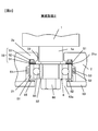
- FIG. 2 is an enlarged view of a region II surrounded by a two-dot chain line in FIG.
- the base 2 is formed with a bearing accommodating portion 21 corresponding to the shaft 1.
- the support portion 2 a of the base 2 is formed by closing the upper portion of the bearing housing portion 21, and a through hole 22 through which the lower end shaft portion 1 a of the shaft 1 is inserted into the bearing housing portion 21 is formed in the support portion 2 a.
- the ball bearing 8 is disposed in the bearing housing portion 21 and is attached to a lower end shaft portion 1 a formed at the lower end of the shaft 1.
- the ball bearing 8 for example, an angular contact ball bearing is used.
- the ball bearing 8 includes an outer ring 81, an inner ring 82, and a rolling element 83 disposed between the outer ring 81 and the inner ring 82.
- Grease for reducing friction with the inner surfaces of the outer ring 81 and the inner ring 82 is applied to the entire surface of the rolling element 83.
- the vibration damping mechanism 50 interposed between the ball bearing 8 and the support portion 2a of the base 2 includes two laminated sliding members 51 and 52, and an elastic body 53 formed of rubber, elastomer, or the like. It has.
- the elastic body 53 is formed in a ring shape, and the upper side thereof is fitted into a recess 22a formed in the support portion 2a.
- the sliding members 51 and 52 are formed in a ring shape, the sliding member 51 is disposed on the upper surface of the outer ring 81 of the ball bearing 8, and the sliding member 52 is disposed on the upper surface of the sliding member 51.
- the sliding member 51 and the sliding member 52 are made of different materials.
- the sliding member 51 disposed in contact with the upper surface of the ball bearing 8 is formed of, for example, a polymer material, and is a sliding member interposed between the sliding member 51 and the elastic body 53.
- the member 52 is made of a metal material.
- the polymer material examples include a fluorine resin such as Teflon (registered trademark), a polyimide resin, a PEEK (polyether ether ketone) resin, and a phenol resin. Further, the polymer material may be impregnated with a lubricating oil. Grease is applied between the upper surface of the ball bearing 8 and the sliding member 51. This grease is not necessarily required and may not be applied.
- a slight gap S ⁇ b> 1 is provided between the outer periphery of the sliding members 51 and 52 and the peripheral wall surface 21 a of the bearing housing portion 21 of the base 2, and the sliding member 51 slides with respect to the upper surface of the ball bearing 8.
- the sliding member 51 is slidable with respect to the sliding member 52.
- the bearing housing portion 21 is provided with an elastic member 61 corresponding to the outer ring 81 of the ball bearing 8.
- the elastic member 61 is formed in a ring shape from rubber, elastomer or the like.
- the inner surface of the elastic member 61 is formed in such a dimension that a slight gap S ⁇ b> 2 is formed between the inner surface of the outer ring 81 of the ball bearing 8.
- a cylindrical holding member 62 is fitted to the lower surface and the outer peripheral surface of the outer ring 81 of the ball bearing 8.
- An attachment member 63 that protrudes to the inside of the bearing housing portion 21 is attached to the base 2 with a fastening member (not shown) or the like.
- a ring-shaped elastic body 65 made of rubber, elastomer or the like is interposed between the cylindrical holding member 62 and the attachment member 63.
- the ball bearing 8 is fixed to the lower end shaft portion 1 a of the shaft 1 by a nut 68 inserted through a through hole 63 a provided in the mounting member 63.
- the shaft 1 has a predetermined position in the axial direction with respect to the magnet holder 11, in other words, the casing 10, due to a repulsive action between the permanent magnet 6 fixed to the rotor 3 and the permanent magnet 7 held by the magnet holder 11. Retained. In this state, the elastic body 53 is compressed and flattened.
- the ball bearing 8 swings with the shaft 1 attached to the rotor 3 due to the unbalance of the rotor 3.
- the deflection of the ball bearing 8 in the radial direction is suppressed by the outer peripheral surface of the outer ring 81 of the ball bearing 8 coming into contact with the elastic member 61. That is, the elastic member 61 has a radial direction damping function that suppresses vibration in the radial direction of the rotor 3.
- the ball bearing 8 swings in the axial direction as well as in the radial direction.
- the sliding member 51 slides relative to the upper surface of the outer ring 81 of the ball bearing 8.
- the sliding member 52 slides relative to the sliding member 51. That is, the contact surface between the upper surface of the outer ring 81 of the ball bearing 8 and the sliding member 51 and the contact surface between the sliding member 51 and the sliding member 52 are the sliding surfaces.
- the elastic body 65 interposed between the cylindrical holding member 62 and the mounting member 63 has a function of absorbing vibration when the load of the rotor 3 acts downward in the axial direction due to some abnormality.
- the friction coefficient between the polymer material and the metal material is smaller than the friction coefficient between the polymer materials or between the metal materials. Therefore, when the outer ring 81 of the ball bearing 8 is formed of a metal material, if the sliding member 51 disposed on the upper surface of the ball bearing 8 is a polymer material, the friction coefficient between the ball bearing 8 and the sliding member 51 is Can be small. Further, when the sliding member 52 is formed of a metal material, the friction coefficient between the sliding member 51 and the sliding member 52 can be reduced. By doing in this way, the vibration suppression effect which prevents that the vibration of the rotor 3 is transmitted to the base 2 and the casing 10 can be enlarged.
- vibration energy transmitted to the base 2 and the housing 10 via the ball bearing 8 can be sufficiently absorbed. That is, the vibration control effect can be improved.
- the vibration damping action can be obtained even when the rotor 3 has a rotational speed other than the rotational speed when passing through the critical speed, that is, at the time of constant speed rotation or the like. Obtainable.
- the sliding members 51 and 52 are made of different materials, and as a preferable example, one is made of a metal material and the other is made of a polymer material. Can be reduced. In this case, if the sliding members 51 and 52 are both made of a polymer material, the frictional resistance is increased, and the polymer material has a low thermal conductivity, and it is highly likely that both members are fixed due to frictional heat. There is a need to. However, also in this case, the vibration damping effect is greater than that of the structure that does not include the sliding members 51 and 52.
- the sliding member 51 may be made of a metal material
- the sliding member 52 may be made of a polymer material
- both of the sliding members 51 and 52 may be made of a metal material.
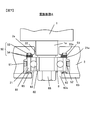
- FIG. 3 is a cross-sectional view showing a second embodiment of the vibration damping mechanism in the vacuum pump of the present invention.
- the vibration control mechanism in the second embodiment is different from the first embodiment shown in FIG. 2 in that a gap is provided around the elastic member 61 and lubricating oil is injected into the gap. That is, a gap S3 is provided between the peripheral wall surface of the bearing accommodating portion 21 and the outer peripheral surface of the elastic member 61, and lubricating oil is injected into the gap S3. Further, the gap S2 between the outer peripheral surface of the outer ring 81 of the ball bearing 8 and the inner peripheral surface of the elastic member 61 is wider than in the first embodiment, and lubricating oil is injected into the gap S2.
- the lubricating oil injected into the gaps S3 and S2 acts as an oil damper when the ball bearing 8 vibrates in the radial direction. That is, the lubricating oil injected into the gaps S3 and S2 together with the elastic member 61 performs a damping function. For this reason, the vibration suppression effect can be improved.
- the dimension of the gap S3 may be about 0.1 to 0.2 mm. Only one of the gaps S3 and S2 into which the lubricating oil is injected may be provided. Others are the same as those of the first embodiment, and the corresponding members are denoted by the same reference numerals and description thereof is omitted.
- FIG. 4 is a cross-sectional view showing a third embodiment of the vibration damping mechanism in the vacuum pump of the present invention
- FIG. 5 is an external perspective view of an elastic member used in the vibration damping mechanism shown in FIG.
- the vibration damping mechanism 50 according to the third embodiment includes one elastic body 53 and four sliding members 51 and 52. That is, in the vibration damping mechanism 50, two sliding members 51 and 52 are used, respectively, and are laminated alternately.
- the stacking order of the sliding members 51 and 52 is the same as that in the first embodiment, and is the order of the ball bearing 8, the sliding member 51, the sliding member 52, the sliding member 51, and the sliding member 52.
- the elastic member 66 has a shape in which a cylindrical metal plate is waved in the radial direction.
- the maximum diameter portion of the elastic member 66 is in contact with the peripheral wall surface of the bearing accommodating portion 21, and the minimum diameter portion is in contact with the outer peripheral surface of the outer ring 81 of the ball bearing 8.
- the vibration damping mechanism shown in the third embodiment is particularly effective for a large vacuum pump.
- the cylindrical holding member 62 is set to have a low height corresponding to the height (axial length) of the elastic member 66.
- Lubricating oil may be applied to either the peripheral wall surface of the bearing housing 21 and the elastic member 66 and / or the outer peripheral surface of the ball bearing 8 and the elastic member 66.
- Others are the same as those of the first embodiment, and the corresponding members are denoted by the same reference numerals and description thereof is omitted.
- FIG. 6 is an external perspective view showing a modification of the elastic member shown in FIG.
- the metal elastic member 67 has a structure in which a plurality of protrusions 67a protruding in the outer peripheral direction are formed on a cylindrical metal plate.
- the protrusions 67 a are arranged at predetermined intervals along the circumferential direction, and the tip portions of the protrusions 67 a are arranged so as to contact the peripheral wall surface of the bearing accommodating portion 21.
- the inner surface of the elastic member 67 is arranged in a positional relationship such that a gap S2 (see FIG. 2) is formed with the outer peripheral surface of the outer ring 81 of the ball bearing 8.
- Lubricating oil may be applied to the inner surface of the elastic member 67 or the outer peripheral surface of the outer ring 81 of the ball bearing 8.
- FIG. 7 is a cross-sectional view showing a fourth embodiment of the vibration damping mechanism in the vacuum pump of the present invention.
- the sliding members 51 and 52 constituting the vibration damping mechanism 50 are exemplified as a structure in which one is made of a polymer material and the other is made of a metal material.
- a plurality (two in FIG. 7) of sliding members 54 constituting the vibration damping mechanism 50 in the fourth embodiment are each formed of powder sintered metal impregnated with lubricating oil.
- the sliding member 51 formed of a polymer material is worn by friction on the sliding surface.
- the lubricating oil covers the sliding surface when worn.
- the sliding member 54 formed of powdered sintered metal impregnated with lubricating oil By using the sliding member 54 formed of powdered sintered metal impregnated with lubricating oil, wear of the sliding member 54 can be suppressed, and accordingly, the preload acting on the ball bearing 8 is increased. Can be suppressed. In addition, since the sliding member 54 formed of powder sintered metal has a large heat transfer coefficient, it is possible to improve the heat dissipating property to dissipate heat through the base 2 and the casing 10, and the temperature of the ball bearing 8 and the rotor 3 Can be lowered.
- the sliding member 54 formed of the powder sintered metal is not limited to two, and can be three or more. It is not necessary for all the sliding members 54 to be impregnated with the lubricating oil, and at least one sliding member 54 only needs to be impregnated with the lubricating oil.
- the radial vibration damping mechanism including the elastic members 61, 66 and 67 may have the structure exemplified in the second and third embodiments.
- FIG. 8 is a cross-sectional view showing a fifth embodiment of the vibration damping mechanism in the vacuum pump of the present invention.
- the vibration damping mechanism 50 according to the fifth embodiment is configured by laminating a sliding member 51 formed of a polymer material and a sliding member 54 formed of powder sintered metal.
- FIG. 8 illustrates a laminated structure in which a sliding member 54 formed of a polymer material is stacked on the top and bottom with a sliding member 54 formed of powder sintered metal as a center.
- it is not limited to the laminated structure illustrated in FIG. It is good also as a laminated structure which laminated
- Embodiment 1 it is good also as a structure which laminated
- the sliding members 54 formed of powder sintered metal it is not necessary for all of the sliding members 54 formed of powder sintered metal to be impregnated with lubricating oil. However, it is preferable to use at least one that is impregnated with a lubricating oil. Further, the sliding member 51 formed of a polymer material may be impregnated with lubricating oil. Regardless of the vertical position of the sliding member 54 formed of powder sintered metal and the sliding member 51 formed of a polymer material, either the sliding member 54 or the sliding member 51 is disposed on the ball bearing 8. May be. Further, either the sliding member 54 or the sliding member 51 may be in contact with the elastic body 53. Further, the radial vibration damping mechanism including the elastic members 61, 66 and 67 may have the structure exemplified in the second and third embodiments.
- the vibration damping mechanism 50 is provided between the support portion 2a and the ball bearing 8.
- the vibration damping mechanism 50 according to the first to third embodiments includes an elastic body 53 and a plurality of laminated sliding members 51 and 52.
- the vibration damping mechanism 50 according to the fourth embodiment is laminated with the elastic body 53.
- the vibration damping mechanism 50 according to the fifth embodiment includes a plurality of sliding members 54, and includes an elastic body 53 and a plurality of stacked sliding members 51 and 54.
- sliding is relatively performed between the sliding members 51 and 52 and between the sliding member 51 and the ball bearing 8.
- the sliding is relatively performed between the two sliding members 54 and 54 and between the sliding member 54 and the ball bearing 8.
- the sliding is relatively performed between the plurality of sliding members 51 and 54 and between the sliding member 51 and the ball bearing 8. Therefore, since it slides relatively on a plurality of contact surfaces, a large vibration damping effect can be obtained.
- the sliding member 51 formed of a polymer material and the sliding member 52 formed of a metal material are alternately stacked. For this reason, the friction coefficient in each sliding surface can be made smaller, and the vibration transmitted to the base 2 and the casing 10 by the vibration of the rotor 3 can be made extremely small.
- the vibration damping mechanism 50 includes at least one sliding member 54 formed of powdered sintered metal impregnated with lubricating oil.
- wear on the sliding surface can be suppressed. That is, for example, wear on the sliding surface can be reduced as compared with the sliding member 51 formed of a polymer material.
- the change of the preload of the vacuum pump in which the preload is applied to the ball bearing 8 by the action of the permanent magnet type magnetic bearing can be suppressed.
- the sliding member is configured by only the sliding member 54 formed of powder sintered metal and having a large heat transfer coefficient, so that the base 2 and the casing 10 are interposed. It is possible to improve the heat dissipating property to dissipate heat and lower the temperature of the ball bearing 8 and the rotor 3.
- the sliding members 51 and 52 are illustrated as being entirely formed of a metal material or a polymer material.
- the sliding members 51 and 52 are not entirely formed of the same material, but may be formed of materials having different surface layers.
- a polymer material may be coated on the metal material, or a metal layer may be formed on the ceramic by sputtering.
- one or both of the sliding members 51 and 52 are formed of, for example, a metal material or a metal oxide, and a smooth micro dome-shaped raised body for smooth sliding is formed on the surface. Also good.
- the present invention can be applied not only to a turbo molecular pump but also to a vacuum pump having a similar bearing structure, for example, a vacuum pump such as a drag pump.
- a vacuum pump such as a drag pump.
- the present invention is not limited to the above embodiment within the scope of the gist of the present invention.
Landscapes
- Engineering & Computer Science (AREA)
- General Engineering & Computer Science (AREA)
- Mechanical Engineering (AREA)
- Physics & Mathematics (AREA)
- Electromagnetism (AREA)
- Non-Positive Displacement Air Blowers (AREA)
- Support Of The Bearing (AREA)
- Sliding-Contact Bearings (AREA)
Description
ターボ分子ポンプのロータの回転周波数は、回転体の共振周波数(2次の危険速度)よりも高い周波数であるため、ポンプ起動および停止時には、この共振周波数(危険速度)を通過させる必要がある。このため、ターボ分子ポンプには、ロータの共振による振動が、ハウジングに伝達されるのを減衰するための制振機構が必要とされる。
本発明の第2の態様によると、第1の態様の真空ポンプは、複数の摺動部材は、表面が異なる材料により形成された、少なくとも2種類の摺動部材を含むことが好ましい。
本発明の第3の態様によると、第2の態様の真空ポンプは、2種類の摺動部材の一方は、少なくとも表面が金属材料により形成され、他方は、少なくとも表面がポリマー材料により形成されていることが好ましい。
本発明の第4の態様によると、第3の態様の真空ポンプは、摺動部材の一方は粉末焼結金属により形成され、粉末焼結金属に潤滑油が含浸されている、ことが好ましい。
本発明の第5の態様によると、第3または第4の態様の真空ポンプは、ポリマー材料は、フッ素樹脂、ポリイミド、PEEK、フェノール樹脂のいずれかであることが好ましい。
本発明の第6の態様によると、第3乃至第5のいずれかの態様の真空ポンプは、ポリマー材料には、潤滑油が含浸されていることが好ましい。
本発明の第7の態様によると、第3の態様の真空ポンプは、少なくとも表面が金属材料により形成された摺動部材と、少なくとも表面がポリマー材料により形成された摺動部材とが交互に積層されていることが好ましい。
本発明の第8の態様によると、第の態様の真空ポンプは、ボールベアリングに接する摺動部材は、少なくとも表面がポリマー材料により形成され、弾性体に接する摺動部材は、少なくとも表面が金属材料により形成されていることが好ましい。
本発明の第9の態様によると、第1の態様の真空ポンプは、複数の摺動部材は、潤滑油が含浸された粉末焼結金属により形成された摺動部材を、少なくとも、1つ含むことが好ましい。
本発明の第10の態様によると、第9の態様の真空ポンプは、複数の摺動部材は、すべて、粉末焼結金属により形成されていることが好ましい。
以下、図を参照して本発明を実施するための形態について説明する。図1は本発明に係る真空ポンプの一実施形態を示す図であり、ターボ分子ポンプの断面図である。ロータ3には排気機能部として回転翼30と円筒部31とが形成されている。回転翼30に対応してケーシング10の内側に固定翼20がスペーサリング5で位置合せされて設けられており、回転翼30と固定翼20とにより高真空側排気機能部を構成している。なお、円筒部31に対応してケーシング10の内側に、円筒部31と共に、例えば、ねじ溝排気部等の低真空側排気機能部を構成する固定筒が設けられているが、図1では図示を省略した。
ハウジング内には、シャフト1が、その軸芯をハウジングの中心部に一致させて収容されている。
ロータ3は、シャフト1と同軸にされてシャフト1に締結されている。シャフト1はモータ4により回転駆動される。シャフト1が締結されたロータ3は、永久磁石6、7を用いた磁気軸受とボールベアリング8とにより回転自在に支持されている。円筒状の永久磁石6はロータ3に固定されている。一方、固定側の永久磁石7は磁石ホルダ11に保持され、永久磁石6の内周側に対向配置されている。永久磁石6、7は、永久磁石式磁気軸受を構成する。ボールベアリング8は、グリース潤滑式の軸受である。
ベース2には、シャフト1に対応してベアリング収容部21が形成されている。ベース2の支持部2aは、ベアリング収容部21の上方を塞いで形成され、支持部2aにはシャフト1の下端軸部1aをベアリング収容部21に挿通する貫通孔22が形成されている。
ボールベアリング8は、ベアリング収容部21内に配置され、シャフト1の下端に形成された下端軸部1aに取り付けられている。ボールベアリング8としては、例えば、アンギュラコンタクト玉軸受が用いられる。ボールベアリング8は、外輪81、内輪82および外輪81と内輪82との間に配置された転がり素子83を有する。転がり素子83の全表面には、外輪81および内輪82の各内面との摩擦を低減するためのグリースが塗着されている。
弾性体53はリング状に形成され、その上部側が支持部2aに形成された凹部22a内に嵌入されている。
ボールベアリング8は、取付部材63に設けられた貫通孔63aから挿通されるナット68によりシャフト1の下端軸部1aに固定されている。
筒形保持部材62と取付部材63との間に介装された弾性体65は、何らかの異常により、ロータ3の荷重が軸方向下方に向けて作用した場合に、振動を吸収する制振する機能を有する。
制振作用は、ロータ3が危険速度を通過する際の回転数以外の回転数の場合、すなわち、定速回転時等においても得られるが、その場合にも、同様に、大きな制振効果を得ることができる。
図3は、本発明の真空ポンプにおける制振機構の実施形態2を示す断面図である。
実施形態2における制振機構が、図2に図示された実施形態1と相違する点は、弾性部材61の周囲に間隙を設けて、この間隙に潤滑油を注入する構造とした点である。
すなわち、ベアリング収容部21の周壁面と弾性部材61の外周面との間に間隙S3が設けられ、この間隙S3に潤滑油が注入されている。また、ボールベアリング8の外輪81の外周面と弾性部材61の内周面との間の間隙S2が、実施形態1の場合よりも拡げられ、この間隙S2に潤滑油が注入されている。
潤滑油が注入される間隙S3、S2は、いずれか一方のみを設ける構造としてもよい。
その他は、実施形態1と同様であり、対応する部材に同一の符号を付して説明を略す。
図4は、本発明の真空ポンプにおける制振機構の実施形態3を示す断面図であり、図5は、図4に示された制振機構に用いられる弾性部材の外観斜視図である。
以下、実施形態1との相違点を主に実施形態3における制振機構を説明する。
実施形態3の制振機構50では、1つの弾性体53と4つの摺動部材51、52により構成されている。
すなわち、制振機構50は、摺動部材51と52が、それぞれ、2つずつ用いられ、交互に積層されている。摺動部材51、52の積層順序は、実施形態1の場合と同様であり、ボールベアリング8、摺動部材51、摺動部材52、摺動部材51、摺動部材52の順である。
弾性部材66は、図5に図示されるように、円筒状の金属板を半径方向に波立たせた形状を有する。弾性部材66の最大径の部分は、ベアリング収容部21の周壁面に接面し、最小径の部分は、ボールベアリング8の外輪81の外周面に接面している。
筒形保持部材62は、その高さが、弾性部材66の高さ(軸方向の長さ)に対応して低く設定されている。
ベアリング収容部21の周壁面と弾性部材66のいずれか一方、および/またはボールベアリング8の外周面と弾性部材66のいずれか一方に、潤滑油を塗布するようにしてもよい。
その他は、実施形態1と同様であり、対応する部材に同一の符号を付して説明を略す。
図6は、図5に図示された弾性部材の変形例を示す外観斜視図である。
金属製の弾性部材67は、円筒状の金属板に外周方向に突出す複数の突起部67aが形成された構造を有する。突起部67aは、円周方向に沿って所定間隔で配列されており、各突起部67aの先端部分が、ベアリング収容部21の周壁面に接するように配置される。弾性部材67は、その内面が、ボールベアリング8の外輪81の外周面と間隙S2(図2参照)が形成されるような位置関係に配置される。弾性部材67の内面またはボールベアリング8の外輪81の外周面に潤滑油を塗布するようにしてもよい。
図7は、本発明の真空ポンプにおける制振機構の実施形態4を示す断面図である。
実施形態1~3においては、制振機構50を構成する摺動部材51、52を、一方をポリマー材料、他方を金属材料により形成した構造として例示した。
実施形態4における制振機構50を構成する複数(図7では2つ)の摺動部材54は、それぞれ、潤滑油が含浸された粉末焼結金属により形成されている。
摺動部材51が摩耗すると、ロータ3に固定されている永久磁石6の位置が下方にずれる。つまり、永久磁石6と磁石ホルダ11に固定された永久磁石7とのスラスト方向の距離が変化する。このため、永久磁石6と永久磁石7との反発力によりボールベアリング8に作用する予圧が増大する。ボールベアリング8に作用する予圧が増大すると、ボールベアリング8が損傷したり、振動が増大したりする。
また、粉末焼結金属により形成された摺動部材54は熱伝達率が大きいので、ベース2とケーシング10とを介して放熱する放熱性を向上することができ、ボールベアリング8およびロータ3の温度を下げることができる。
また、弾性部材61、66、67を含む半径方向制振機構は、実施形態2および3に例示された構造としてもよい。
図8は、本発明の真空ポンプにおける制振機構の実施形態5を示す断面図である。
実施形態5における制振機構50は、ポリマー材料で形成された摺動部材51と、粉末焼結金属により形成された摺動部材54とが積層されて構成されている。
図8においては、粉末焼結金属により形成された摺動部材54を中央にして、上下にポリマー材料により形成された摺動部材51が積層された積層構造として例示されている。しかし、図8に例示された積層構造に限定されるものではない。ポリマー材料により形成された摺動部材51を中央にして、上下に粉末焼結金属により形成された摺動部材54を積層した積層構造としてもよい。実施形態1のように、粉末焼結金属により形成された摺動部材54とポリマー材料により形成された摺動部材51とを1つずつ積層した構造としてもよい。また、実施形態2のように、粉末焼結金属により形成された摺動部材54とポリマー材料により形成された摺動部材51とを交互に積層した構造としてもよい。
また、弾性部材61、66、67を含む半径方向制振機構は、実施形態2および3に例示された構造としてもよい。
(1)実施形態1~5では、支持部2aとボールベアリング8との間に制振機構50を備えている。実施形態1~3の制振機構50は、弾性体53と、積層された複数の摺動部材51、52とを備え、実施形態4の制振機構50は、弾性体53と、積層された複数の摺動部材54とを備え、実施形態5の制振機構50は、弾性体53と、積層された複数の摺動部材51,54とを備えている。実施形態1~3では摺動部材51と52との間、および摺動部材51とボールベアリング8との間において相対的に摺動する。実施形態4では2枚の摺動部材54と54との間、および摺動部材54とボールベアリング8との間において相対的に摺動する。実施形態5では複数の摺動部材51と54との間、および摺動部材51とボールベアリング8との間において相対的に摺動する。したがって、複数の接触面において相対的に摺動するので、大きな制振効果を得ることができる。
その他、本発明の趣旨の範囲内において、本発明は上記実施の形態に何ら限定されるものではない。
日本国特許出願2012年第85412号(2012年4月4日出願)
Claims (10)
- 排気機能部が形成されたロータを、ボールベアリングと永久磁石式磁気軸受とで支持し、前記ロータをモータにより高速回転させて真空排気する真空ポンプにおいて、
前記ロータに設けられたシャフトと、
前記シャフトに取り付けられた前記ボールベアリングと、
前記シャフトの軸方向における前記ボールベアリングと前記永久磁石式磁気軸受との間に配置された支持部材と、
前記支持部材と前記ボールベアリングとの間に介装された制振機構と、を備え、
前記制振機構は、前記支持部材と前記ボールベアリングとの間に介装された弾性体と、
前記弾性体と前記ボールベアリングとの間に積層して介装された複数の摺動部材と、を備える、真空ポンプ。 - 請求項1に記載の真空ポンプにおいて、前記複数の摺動部材は、表面が異なる材料により形成された、少なくとも2種類の摺動部材を含む、真空ポンプ。
- 請求項2に記載の真空ポンプにおいて、2種類の前記摺動部材の一方は、少なくとも表面が金属材料により形成され、他方は、少なくとも表面がポリマー材料により形成されている、真空ポンプ。
- 請求項3に記載の真空ポンプにおいて、前記摺動部材の一方は粉末焼結金属により形成され、前記粉末焼結金属に潤滑油が含浸されている、真空ポンプ。
- 請求項3または4に記載の真空ポンプにおいて、前記ポリマー材料は、フッ素樹脂、ポリイミド、PEEK、フェノール樹脂のいずれかである、真空ポンプ。
- 請求項3乃至5のいずれか1項に記載の真空ポンプにおいて、前記ポリマー材料には、潤滑油が含浸されている、真空ポンプ。
- 請求項3に記載の真空ポンプにおいて、少なくとも表面が前記金属材料により形成された前記摺動部材と、少なくとも表面が前記ポリマー材料により形成された前記摺動部材とが交互に積層されている、真空ポンプ。
- 請求項7に記載の真空ポンプにおいて、前記ボールベアリングに接する前記摺動部材は、少なくとも表面が前記ポリマー材料により形成され、前記弾性体に接する前記摺動部材は、少なくとも表面が前記金属材料により形成されている、真空ポンプ。
- 請求項1に記載の真空ポンプにおいて、前記複数の摺動部材は、潤滑油が含浸された粉末焼結金属により形成された摺動部材を、少なくとも、1つ含む、真空ポンプ。
- 請求項9に記載の真空ポンプにおいて、前記複数の摺動部材は、すべて、粉末焼結金属材料により形成されている、真空ポンプ。
Priority Applications (3)
| Application Number | Priority Date | Filing Date | Title |
|---|---|---|---|
| JP2014509156A JP5999176B2 (ja) | 2012-04-04 | 2013-04-01 | 真空ポンプ |
| US14/383,728 US10590961B2 (en) | 2012-04-04 | 2013-04-01 | Vacuum pump |
| CN201380005388.8A CN104185736B (zh) | 2012-04-04 | 2013-04-01 | 真空泵 |
Applications Claiming Priority (2)
| Application Number | Priority Date | Filing Date | Title |
|---|---|---|---|
| JP2012-085412 | 2012-04-04 | ||
| JP2012085412 | 2012-04-04 |
Publications (1)
| Publication Number | Publication Date |
|---|---|
| WO2013151015A1 true WO2013151015A1 (ja) | 2013-10-10 |
Family
ID=49300498
Family Applications (1)
| Application Number | Title | Priority Date | Filing Date |
|---|---|---|---|
| PCT/JP2013/059961 Ceased WO2013151015A1 (ja) | 2012-04-04 | 2013-04-01 | 真空ポンプ |
Country Status (4)
| Country | Link |
|---|---|
| US (1) | US10590961B2 (ja) |
| JP (1) | JP5999176B2 (ja) |
| CN (1) | CN104185736B (ja) |
| WO (1) | WO2013151015A1 (ja) |
Cited By (1)
| Publication number | Priority date | Publication date | Assignee | Title |
|---|---|---|---|---|
| EP3085964A1 (de) * | 2015-04-21 | 2016-10-26 | Pfeiffer Vacuum Gmbh | Herstellung eines vakuumpumpen-teils mittels eines metallischen, generativen fertigungsverfahrens |
Families Citing this family (18)
| Publication number | Priority date | Publication date | Assignee | Title |
|---|---|---|---|---|
| JP6458414B2 (ja) | 2014-09-10 | 2019-01-30 | 株式会社島津製作所 | 真空ポンプ |
| JP2016126197A (ja) * | 2015-01-05 | 2016-07-11 | 株式会社リコー | 現像装置及び画像形成装置 |
| CN113586512B (zh) * | 2015-09-30 | 2023-12-26 | 浙江三花汽车零部件有限公司 | 转子组件以及电驱动泵 |
| JP6638444B2 (ja) * | 2016-02-09 | 2020-01-29 | 株式会社島津製作所 | 真空ポンプ |
| CN105545825A (zh) * | 2016-02-25 | 2016-05-04 | 太仓钰丰机械工程有限公司 | 一种减震缓冲硅油风扇离合器 |
| GB2552700A (en) | 2016-08-04 | 2018-02-07 | Edwards Ltd | Turbomolecular pump lubricant supply systems |
| DE102016012246A1 (de) * | 2016-10-14 | 2018-04-19 | Thyssenkrupp Ag | Elektromechanische Servolenkung mit gefederter Lageranordnung |
| DE102017004272B3 (de) * | 2017-05-04 | 2018-06-28 | Doppstadt Familienholding Gmbh | Vorrichtung zum Klassieren von Klassiergut |
| GB2570006A (en) * | 2018-01-09 | 2019-07-10 | Edwards Ltd | Magnetic bearing and vacuum pump with such a magnetic bearing |
| CN110242601B (zh) * | 2019-06-17 | 2020-07-24 | 天长市远安机械有限公司 | 一种微型涡轮负压泵 |
| US11021998B2 (en) * | 2019-08-08 | 2021-06-01 | General Electric Company | Shape memory alloy sleeve support assembly for a bearing |
| CN111089115B (zh) * | 2020-01-07 | 2024-11-05 | 珠海格力电器股份有限公司 | 一种磁悬浮轴承轴向保护系统 |
| WO2021166136A1 (ja) * | 2020-02-20 | 2021-08-26 | 三菱重工エンジン&ターボチャージャ株式会社 | コンプレッサ |
| FR3117180B1 (fr) * | 2020-10-01 | 2022-11-11 | Valeo Embrayages | Amortissement d’un élément mobile |
| KR102669883B1 (ko) * | 2022-02-08 | 2024-05-28 | (주)엘오티베큠 | 터보 분자 펌프 |
| GB2617843B (en) * | 2022-04-20 | 2024-05-08 | Edwards Ltd | Vacuum pump damping arrangements |
| CN121152924A (zh) * | 2024-04-15 | 2025-12-16 | 广东德昌电机有限公司 | 流体泵 |
| WO2026056363A1 (zh) * | 2024-09-10 | 2026-03-19 | 杭州贝丰科技股份有限公司 | 轴承组件及电机 |
Citations (6)
| Publication number | Priority date | Publication date | Assignee | Title |
|---|---|---|---|---|
| DE8910040U1 (de) * | 1988-09-03 | 1989-12-14 | Leybold Ag | Turbomolekular-Vakuumpumpe |
| JP2006525466A (ja) * | 2003-04-29 | 2006-11-09 | ザ ビーオーシー グループ ピーエルシー | 真空ポンプ |
| JP2008039183A (ja) * | 2006-08-09 | 2008-02-21 | Pfeiffer Vacuum Gmbh | 真空ポンプの軸の支持装置 |
| JP2008121889A (ja) * | 2006-11-11 | 2008-05-29 | Pfeiffer Vacuum Gmbh | 真空ポンプ用軸受モジュールおよび真空ポンプ |
| JP2008261374A (ja) * | 2007-04-10 | 2008-10-30 | Daikin Ind Ltd | 摺動部材およびそれを用いた流体機械 |
| JP2010535969A (ja) * | 2007-08-10 | 2010-11-25 | オーリコン レイボルド バキューム ゲーエムベーハー | ポンプ軸受配置 |
Family Cites Families (8)
| Publication number | Priority date | Publication date | Assignee | Title |
|---|---|---|---|---|
| TW344779B (en) * | 1994-05-30 | 1998-11-11 | Hitachi Ltd | Slide member with self-lubricating functions and production process thereof, and bearing in molten metal and molten metal electroplating device |
| JP4234865B2 (ja) * | 1999-10-28 | 2009-03-04 | オイレス工業株式会社 | 鉄系焼結摺動部材ならびにその製造方法 |
| JP4250353B2 (ja) * | 2001-06-22 | 2009-04-08 | エドワーズ株式会社 | 真空ポンプ |
| DE10320851A1 (de) | 2003-05-09 | 2004-11-25 | Leybold Vakuum Gmbh | Turbopumpe |
| WO2005121288A1 (ja) * | 2004-06-10 | 2005-12-22 | Ntn Corporation | 摺動材料およびすべり軸受 |
| WO2006001243A1 (ja) * | 2004-06-25 | 2006-01-05 | Osaka Vacuum, Ltd. | ターボ分子ポンプの軸受支持構造 |
| JP2006300210A (ja) * | 2005-04-20 | 2006-11-02 | Jtekt Corp | 制振装置および軸受装置 |
| GB0511877D0 (en) | 2005-06-10 | 2005-07-20 | Boc Group Plc | Vacuum pump |
-
2013
- 2013-04-01 JP JP2014509156A patent/JP5999176B2/ja active Active
- 2013-04-01 CN CN201380005388.8A patent/CN104185736B/zh active Active
- 2013-04-01 WO PCT/JP2013/059961 patent/WO2013151015A1/ja not_active Ceased
- 2013-04-01 US US14/383,728 patent/US10590961B2/en active Active
Patent Citations (6)
| Publication number | Priority date | Publication date | Assignee | Title |
|---|---|---|---|---|
| DE8910040U1 (de) * | 1988-09-03 | 1989-12-14 | Leybold Ag | Turbomolekular-Vakuumpumpe |
| JP2006525466A (ja) * | 2003-04-29 | 2006-11-09 | ザ ビーオーシー グループ ピーエルシー | 真空ポンプ |
| JP2008039183A (ja) * | 2006-08-09 | 2008-02-21 | Pfeiffer Vacuum Gmbh | 真空ポンプの軸の支持装置 |
| JP2008121889A (ja) * | 2006-11-11 | 2008-05-29 | Pfeiffer Vacuum Gmbh | 真空ポンプ用軸受モジュールおよび真空ポンプ |
| JP2008261374A (ja) * | 2007-04-10 | 2008-10-30 | Daikin Ind Ltd | 摺動部材およびそれを用いた流体機械 |
| JP2010535969A (ja) * | 2007-08-10 | 2010-11-25 | オーリコン レイボルド バキューム ゲーエムベーハー | ポンプ軸受配置 |
Cited By (2)
| Publication number | Priority date | Publication date | Assignee | Title |
|---|---|---|---|---|
| EP3085964A1 (de) * | 2015-04-21 | 2016-10-26 | Pfeiffer Vacuum Gmbh | Herstellung eines vakuumpumpen-teils mittels eines metallischen, generativen fertigungsverfahrens |
| JP2016205391A (ja) * | 2015-04-21 | 2016-12-08 | プファイファー・ヴァキューム・ゲーエムベーハー | 真空ポンプの部材の製造方法、真空ポンプの部材、及び真空ポンプ |
Also Published As
| Publication number | Publication date |
|---|---|
| US20150132109A1 (en) | 2015-05-14 |
| CN104185736A (zh) | 2014-12-03 |
| JPWO2013151015A1 (ja) | 2015-12-17 |
| JP5999176B2 (ja) | 2016-09-28 |
| US10590961B2 (en) | 2020-03-17 |
| CN104185736B (zh) | 2016-12-28 |
Similar Documents
| Publication | Publication Date | Title |
|---|---|---|
| JP5999176B2 (ja) | 真空ポンプ | |
| JP5919745B2 (ja) | 真空ポンプ | |
| JP5384498B2 (ja) | ポンプ軸受配置 | |
| CN100432446C (zh) | 涡轮分子泵的轴承支承结构 | |
| JP6772721B2 (ja) | 真空ポンプ | |
| US8753069B2 (en) | Eddy current damper and method | |
| CN103850978A (zh) | 滚动轴承的支承件 | |
| JP6031102B2 (ja) | 磁性流体シール | |
| US10069377B2 (en) | Flywheel assembly | |
| WO2019044722A1 (ja) | 渦電流式ダンパ | |
| JP5718327B2 (ja) | シール用回転出力ユニットおよびシール用モータアセンブリ | |
| WO2019054278A1 (ja) | 渦電流式ダンパ | |
| JP6458414B2 (ja) | 真空ポンプ | |
| JP2014173431A (ja) | 真空ポンプ | |
| JP2019100438A (ja) | 渦電流式ダンパ | |
| JP6295773B2 (ja) | 真空ポンプ | |
| WO2021166136A1 (ja) | コンプレッサ | |
| JP7101556B2 (ja) | 渦電流式ダンパ | |
| JP2019078332A (ja) | 渦電流式ダンパ | |
| JP2014058932A (ja) | 真空ポンプ | |
| JP6186632B1 (ja) | 回転機械 | |
| JP6831361B2 (ja) | 真空ポンプ | |
| JP2019078331A (ja) | 渦電流式ダンパ | |
| JP2009138717A (ja) | 分子ポンプの軸受支持構造 |
Legal Events
| Date | Code | Title | Description |
|---|---|---|---|
| 121 | Ep: the epo has been informed by wipo that ep was designated in this application |
Ref document number: 13772526 Country of ref document: EP Kind code of ref document: A1 |
|
| ENP | Entry into the national phase |
Ref document number: 2014509156 Country of ref document: JP Kind code of ref document: A |
|
| WWE | Wipo information: entry into national phase |
Ref document number: 14383728 Country of ref document: US |
|
| NENP | Non-entry into the national phase |
Ref country code: DE |
|
| 122 | Ep: pct application non-entry in european phase |
Ref document number: 13772526 Country of ref document: EP Kind code of ref document: A1 |