WO2013153627A1 - ガソリン機関の制御装置 - Google Patents
ガソリン機関の制御装置 Download PDFInfo
- Publication number
- WO2013153627A1 WO2013153627A1 PCT/JP2012/059861 JP2012059861W WO2013153627A1 WO 2013153627 A1 WO2013153627 A1 WO 2013153627A1 JP 2012059861 W JP2012059861 W JP 2012059861W WO 2013153627 A1 WO2013153627 A1 WO 2013153627A1
- Authority
- WO
- WIPO (PCT)
- Prior art keywords
- fuel
- fuel injection
- engine
- injection valve
- heated
- Prior art date
- Legal status (The legal status is an assumption and is not a legal conclusion. Google has not performed a legal analysis and makes no representation as to the accuracy of the status listed.)
- Ceased
Links
Images




Classifications
-
- F—MECHANICAL ENGINEERING; LIGHTING; HEATING; WEAPONS; BLASTING
- F02—COMBUSTION ENGINES; HOT-GAS OR COMBUSTION-PRODUCT ENGINE PLANTS
- F02M—SUPPLYING COMBUSTION ENGINES IN GENERAL WITH COMBUSTIBLE MIXTURES OR CONSTITUENTS THEREOF
- F02M31/00—Apparatus for thermally treating combustion-air, fuel, or fuel-air mixture
- F02M31/02—Apparatus for thermally treating combustion-air, fuel, or fuel-air mixture for heating
- F02M31/12—Apparatus for thermally treating combustion-air, fuel, or fuel-air mixture for heating electrically
- F02M31/125—Fuel
-
- F—MECHANICAL ENGINEERING; LIGHTING; HEATING; WEAPONS; BLASTING
- F02—COMBUSTION ENGINES; HOT-GAS OR COMBUSTION-PRODUCT ENGINE PLANTS
- F02D—CONTROLLING COMBUSTION ENGINES
- F02D31/00—Use of speed-sensing governors to control combustion engines, not otherwise provided for
- F02D31/001—Electric control of rotation speed
- F02D31/007—Electric control of rotation speed controlling fuel supply
- F02D31/008—Electric control of rotation speed controlling fuel supply for idle speed control
-
- F—MECHANICAL ENGINEERING; LIGHTING; HEATING; WEAPONS; BLASTING
- F02—COMBUSTION ENGINES; HOT-GAS OR COMBUSTION-PRODUCT ENGINE PLANTS
- F02D—CONTROLLING COMBUSTION ENGINES
- F02D41/00—Electrical control of supply of combustible mixture or its constituents
- F02D41/02—Circuit arrangements for generating control signals
- F02D41/04—Introducing corrections for particular operating conditions
- F02D41/06—Introducing corrections for particular operating conditions for engine starting or warming up
- F02D41/068—Introducing corrections for particular operating conditions for engine starting or warming up for warming-up
-
- F—MECHANICAL ENGINEERING; LIGHTING; HEATING; WEAPONS; BLASTING
- F02—COMBUSTION ENGINES; HOT-GAS OR COMBUSTION-PRODUCT ENGINE PLANTS
- F02D—CONTROLLING COMBUSTION ENGINES
- F02D41/00—Electrical control of supply of combustible mixture or its constituents
- F02D41/02—Circuit arrangements for generating control signals
- F02D41/04—Introducing corrections for particular operating conditions
- F02D41/08—Introducing corrections for particular operating conditions for idling
-
- F—MECHANICAL ENGINEERING; LIGHTING; HEATING; WEAPONS; BLASTING
- F02—COMBUSTION ENGINES; HOT-GAS OR COMBUSTION-PRODUCT ENGINE PLANTS
- F02D—CONTROLLING COMBUSTION ENGINES
- F02D41/00—Electrical control of supply of combustible mixture or its constituents
- F02D41/02—Circuit arrangements for generating control signals
- F02D41/04—Introducing corrections for particular operating conditions
- F02D41/12—Introducing corrections for particular operating conditions for deceleration
- F02D41/123—Introducing corrections for particular operating conditions for deceleration the fuel injection being cut-off
-
- F—MECHANICAL ENGINEERING; LIGHTING; HEATING; WEAPONS; BLASTING
- F02—COMBUSTION ENGINES; HOT-GAS OR COMBUSTION-PRODUCT ENGINE PLANTS
- F02D—CONTROLLING COMBUSTION ENGINES
- F02D41/00—Electrical control of supply of combustible mixture or its constituents
- F02D41/02—Circuit arrangements for generating control signals
- F02D41/04—Introducing corrections for particular operating conditions
- F02D41/12—Introducing corrections for particular operating conditions for deceleration
- F02D41/123—Introducing corrections for particular operating conditions for deceleration the fuel injection being cut-off
- F02D41/126—Introducing corrections for particular operating conditions for deceleration the fuel injection being cut-off transitional corrections at the end of the cut-off period
-
- F—MECHANICAL ENGINEERING; LIGHTING; HEATING; WEAPONS; BLASTING
- F02—COMBUSTION ENGINES; HOT-GAS OR COMBUSTION-PRODUCT ENGINE PLANTS
- F02D—CONTROLLING COMBUSTION ENGINES
- F02D41/00—Electrical control of supply of combustible mixture or its constituents
- F02D41/30—Controlling fuel injection
- F02D41/3005—Details not otherwise provided for
-
- F—MECHANICAL ENGINEERING; LIGHTING; HEATING; WEAPONS; BLASTING
- F02—COMBUSTION ENGINES; HOT-GAS OR COMBUSTION-PRODUCT ENGINE PLANTS
- F02D—CONTROLLING COMBUSTION ENGINES
- F02D41/00—Electrical control of supply of combustible mixture or its constituents
- F02D41/30—Controlling fuel injection
- F02D41/3094—Controlling fuel injection the fuel injection being effected by at least two different injectors, e.g. one in the intake manifold and one in the cylinder
-
- F—MECHANICAL ENGINEERING; LIGHTING; HEATING; WEAPONS; BLASTING
- F02—COMBUSTION ENGINES; HOT-GAS OR COMBUSTION-PRODUCT ENGINE PLANTS
- F02D—CONTROLLING COMBUSTION ENGINES
- F02D41/00—Electrical control of supply of combustible mixture or its constituents
- F02D41/30—Controlling fuel injection
- F02D41/32—Controlling fuel injection of the low pressure type
-
- F—MECHANICAL ENGINEERING; LIGHTING; HEATING; WEAPONS; BLASTING
- F02—COMBUSTION ENGINES; HOT-GAS OR COMBUSTION-PRODUCT ENGINE PLANTS
- F02M—SUPPLYING COMBUSTION ENGINES IN GENERAL WITH COMBUSTIBLE MIXTURES OR CONSTITUENTS THEREOF
- F02M53/00—Fuel-injection apparatus characterised by having heating, cooling or thermally-insulating means
- F02M53/02—Fuel-injection apparatus characterised by having heating, cooling or thermally-insulating means with fuel-heating means, e.g. for vaporising
-
- F—MECHANICAL ENGINEERING; LIGHTING; HEATING; WEAPONS; BLASTING
- F02—COMBUSTION ENGINES; HOT-GAS OR COMBUSTION-PRODUCT ENGINE PLANTS
- F02M—SUPPLYING COMBUSTION ENGINES IN GENERAL WITH COMBUSTIBLE MIXTURES OR CONSTITUENTS THEREOF
- F02M53/00—Fuel-injection apparatus characterised by having heating, cooling or thermally-insulating means
- F02M53/04—Injectors with heating, cooling, or thermally-insulating means
- F02M53/06—Injectors with heating, cooling, or thermally-insulating means with fuel-heating means, e.g. for vaporising
-
- F—MECHANICAL ENGINEERING; LIGHTING; HEATING; WEAPONS; BLASTING
- F02—COMBUSTION ENGINES; HOT-GAS OR COMBUSTION-PRODUCT ENGINE PLANTS
- F02M—SUPPLYING COMBUSTION ENGINES IN GENERAL WITH COMBUSTIBLE MIXTURES OR CONSTITUENTS THEREOF
- F02M69/00—Low-pressure fuel-injection apparatus ; Apparatus with both continuous and intermittent injection; Apparatus injecting different types of fuel
- F02M69/04—Injectors peculiar thereto
- F02M69/042—Positioning of injectors with respect to engine, e.g. in the air intake conduit
- F02M69/044—Positioning of injectors with respect to engine, e.g. in the air intake conduit for injecting into the intake conduit downstream of an air throttle valve
-
- F—MECHANICAL ENGINEERING; LIGHTING; HEATING; WEAPONS; BLASTING
- F02—COMBUSTION ENGINES; HOT-GAS OR COMBUSTION-PRODUCT ENGINE PLANTS
- F02M—SUPPLYING COMBUSTION ENGINES IN GENERAL WITH COMBUSTIBLE MIXTURES OR CONSTITUENTS THEREOF
- F02M69/00—Low-pressure fuel-injection apparatus ; Apparatus with both continuous and intermittent injection; Apparatus injecting different types of fuel
- F02M69/04—Injectors peculiar thereto
- F02M69/042—Positioning of injectors with respect to engine, e.g. in the air intake conduit
- F02M69/046—Positioning of injectors with respect to engine, e.g. in the air intake conduit for injecting into both the combustion chamber and the intake conduit
-
- F—MECHANICAL ENGINEERING; LIGHTING; HEATING; WEAPONS; BLASTING
- F02—COMBUSTION ENGINES; HOT-GAS OR COMBUSTION-PRODUCT ENGINE PLANTS
- F02D—CONTROLLING COMBUSTION ENGINES
- F02D2200/00—Input parameters for engine control
- F02D2200/02—Input parameters for engine control the parameters being related to the engine
- F02D2200/06—Fuel or fuel supply system parameters
- F02D2200/0606—Fuel temperature
-
- F—MECHANICAL ENGINEERING; LIGHTING; HEATING; WEAPONS; BLASTING
- F02—COMBUSTION ENGINES; HOT-GAS OR COMBUSTION-PRODUCT ENGINE PLANTS
- F02D—CONTROLLING COMBUSTION ENGINES
- F02D2200/00—Input parameters for engine control
- F02D2200/02—Input parameters for engine control the parameters being related to the engine
- F02D2200/10—Parameters related to the engine output, e.g. engine torque or engine speed
- F02D2200/101—Engine speed
-
- Y—GENERAL TAGGING OF NEW TECHNOLOGICAL DEVELOPMENTS; GENERAL TAGGING OF CROSS-SECTIONAL TECHNOLOGIES SPANNING OVER SEVERAL SECTIONS OF THE IPC; TECHNICAL SUBJECTS COVERED BY FORMER USPC CROSS-REFERENCE ART COLLECTIONS [XRACs] AND DIGESTS
- Y02—TECHNOLOGIES OR APPLICATIONS FOR MITIGATION OR ADAPTATION AGAINST CLIMATE CHANGE
- Y02T—CLIMATE CHANGE MITIGATION TECHNOLOGIES RELATED TO TRANSPORTATION
- Y02T10/00—Road transport of goods or passengers
- Y02T10/10—Internal combustion engine [ICE] based vehicles
- Y02T10/12—Improving ICE efficiencies
Definitions
- the present invention relates to a control device for a gasoline engine.
- a gasoline engine includes a port type fuel injection valve that injects fuel into an intake port, a type that includes a direct injection type fuel injection valve that directly injects fuel into a cylinder, or both of these fuel injection valves.
- a port type fuel injection valve that injects fuel into an intake port
- a type that includes a direct injection type fuel injection valve that directly injects fuel into a cylinder or both of these fuel injection valves.
- Patent Document 1 describes a gasoline engine having both a port type fuel injection valve and a direct injection type fuel injection valve, and a control device for controlling the gasoline engine.
- Gasoline engine exhaust contains air pollutants such as particulate matter (PM), carbon monoxide, and hydrocarbons. For this reason, the regulation of the emission amount of such air pollutants has been conventionally performed, and in recent years, the regulation of the emission amount has become particularly strict. Specifically, in a test using the gasoline engine, PM in exhaust gas is collected by a filter, and the mass of the collected PM is measured. Here, it is required that the mass of the collected PM is not more than a reference value.
- PM particulate matter
- carbon monoxide carbon monoxide
- hydrocarbons hydrocarbons
- the number of PM particles is required to be equal to or less than a reference number.
- the reference number is expected to tend to be further reduced in the future.
- the number of PM particles in the exhaust gas can be suitably regulated regardless of the particle size of PM.
- An object of the present invention is to provide a control device for a gasoline engine capable of suitably reducing the number of particles of particulate matter in the exhaust gas even when a filter for collecting particulate matter is not provided in the exhaust passage. It is in.
- a control device for a gasoline engine controls a gasoline engine provided with an electric heating device that heats fuel in a portion upstream of a nozzle hole of a fuel injection valve in a fuel supply system. .
- the control device heats the fuel by the heating device when the engine is cold.
- the heated fuel is injected from the fuel injection valve when the engine is cold, atomization of the injected fuel is promoted. Therefore, in the fuel injection valve that injects fuel into the intake port, the fuel is prevented from adhering to the inner wall of the intake port, and in the fuel injection valve that directly injects fuel into the cylinder, the fuel is injected into the inner wall of the cylinder. It is possible to suppress the adhesion of fuel. As a result, the amount of fuel droplets remaining until combustion is started in the cylinder can be reduced, and the degree of premixing of fuel and air can be increased. Therefore, even when no filter for collecting particulate matter is provided in the exhaust passage, the number of particulate matter particles in the exhaust can be suitably reduced.
- the engine rotation speed when the fuel injected from the fuel injection valve is heated by the heating device is injected from the fuel injection valve by the heating device.
- a mode in which the fuel injection amount by the fuel injection valve is controlled so as to be less than the engine rotation speed (non-heating idle rotation speed) when the fuel to be heated is not heated is preferable.
- the fuel injection amount is increased when the idling operation is performed when the engine is cold compared to when the engine is warm. Specifically, the fuel injection amount is controlled so that the engine rotation speed becomes higher than the idle rotation speed when the engine is warm (the non-heating idle rotation speed).
- the fuel is heated by the heating device, whereby the atomization of the fuel is promoted. For this reason, it is possible to suppress instability of the engine operation without increasing the engine rotation speed to the non-heating idle rotation speed.
- the gasoline engine is heated compared to the configuration in which the fuel injected from the fuel injection valve is heated by the heating device and the fuel injection amount is controlled so that the engine rotation speed becomes the non-heating idle rotation speed. The amount of fuel consumed can be reduced. Accordingly, when the engine is cold and the idling operation is performed, the fuel consumption can be reduced while suppressing the instability of the engine operation.
- the heating device is operated by electric power supplied from a battery, and the battery is configured to charge electric power generated by an engine-driven generator, and is idling when the engine is cold.
- the heating mode by the heating device and the fuel injection valve are reduced so that the fuel consumption of the gasoline engine is smaller than when the fuel is not heated.
- a mode in which the fuel injection amount is controlled is preferable.
- the heating mode by the heating device and the fuel injection valve are used.
- the fuel injection amount By controlling the fuel injection amount, the fuel consumption of the gasoline engine is reduced as compared with the case where the heating is not performed. Therefore, when idling is performed when the engine is cold, fuel consumption can be accurately reduced while suppressing instability of engine operation.
- the amount of fuel injected from the fuel injection valve when the fuel injected from the fuel injection valve is heated by the heating device
- the heating device does not heat the fuel injected from the fuel injection valve when compared under the condition that the other engine operating conditions are the same, the amount of fuel injected from the fuel injection valve (non-heated)
- a mode in which the fuel injection amount is controlled so as to be less than (hour fuel amount) is preferable.
- the fuel injection amount is increased compared to when the engine is warm. I am doing so. Specifically, the fuel injection amount is set to an amount larger than the fuel injection amount when the engine is warm (the non-heating time fuel amount).
- the fuel injected from the fuel injection valve is heated by the heating device when the fuel injection from the fuel injection valve is resumed when the engine is cold, for example, when returning from a fuel cut.
- the fuel atomization is promoted.
- the fuel consumption of the gasoline engine can be reduced as compared with the configuration in which the fuel injected from the fuel injection valve is heated by the heating device and the fuel injection amount is the non-heating time fuel amount. Therefore, according to the above configuration, when starting or restarting fuel injection from the fuel injection valve when the engine is cold, fuel consumption can be reduced while suppressing shortage of engine output.
- the heating device is operated by electric power supplied from a battery, and the battery is configured to charge electric power generated by an engine-driven generator, and from the fuel injection valve when the engine is cold.
- heating by the heating device is such that when the fuel injected from the fuel injection valve is heated by the heating device, the fuel consumption of the gasoline engine is less than when not heating.
- a mode in which the mode and the fuel injection amount by the fuel injection valve are controlled is preferable.
- the gasoline engine includes both a port type fuel injection valve that injects fuel into the intake port and a direct injection type fuel injection valve that directly injects fuel into the cylinder, and the heating device includes the port type fuel injection valve and the direct injection type fuel injection valve.
- the heating device includes the port type fuel injection valve and the direct injection type fuel injection valve.
- the heating device is provided only in the port type fuel injection valve
- the amount of fuel injected from the port type fuel injection valve is increased, fuel atomization is promoted.
- the amount of fuel adhering to the inner wall of the intake port can be reduced.
- the fuel injected from the direct injection fuel injection valve is not heated and the atomization of the fuel is difficult to be promoted, the amount of fuel adhering to the inner wall of the cylinder is reduced because the injection amount is reduced. Will be able to. Therefore, the total amount of fuel adhering to the inner wall of the intake port and the inner wall of the cylinder can be reduced, and the number of particulate matter particles in the exhaust gas can be accurately reduced.
- the engine is cold when the engine temperature is equal to or lower than a predetermined temperature.
- the flowchart which shows the execution procedure of electricity supply control of an electric heater about the control apparatus of the gasoline engine which concerns on 2nd Embodiment of this invention.
- the flowchart which shows the execution procedure of the fuel cut return control in the said 2nd Embodiment. It is a timing chart for demonstrating the effect
- Timing chart for demonstrating the effect
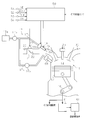
- the gasoline engine of this embodiment is a water-cooled multi-cylinder gasoline engine (hereinafter referred to as an engine) for driving a vehicle.
- FIG. 1 shows a schematic configuration of an engine of the present embodiment and an electronic control device 50 that controls the engine.
- FIG. 1 shows a cross-sectional structure of one cylinder 11.
- a cylinder 12 is provided with a piston 12 so as to be capable of reciprocating.
- a crankshaft 16 is connected to the piston 12, and the crankshaft 16 is configured to be rotationally driven as the piston 12 reciprocates.
- a combustion chamber 14 is defined by the inner wall of the cylinder 11 and the top surface of the piston 12.
- a spark plug 15 is exposed in the combustion chamber 14.
- an intake passage 20 and an exhaust passage 30 are connected to the cylinder 11.
- a throttle body 21 that accommodates a throttle valve 22 is provided in the intake passage 20.
- the throttle valve 22 is driven to open and close by a throttle motor 23.
- the intake passage 20 is connected to the cylinder 11 via an intake port 24.
- the engine is provided with a fuel supply system 17 for supplying fuel.
- the fuel supply system 17 includes a fuel tank 17a that stores fuel, a fuel pump 17b that sucks and discharges the fuel tank in the fuel tank 17a, a supply passage 17c that pumps the discharged fuel, and the pressure pump
- a fuel injection valve 18 for injecting fuel into the intake port 2 from the injection hole 18a is provided.
- the fuel injection valve 18 includes an electric heater that heats the fuel inside the fuel injection valve 18, in other words, the fuel in a portion upstream of the injection hole 18 a in the fuel supply system 17 including the fuel injection valve 18. 19 is built in.
- the electric heater 19 is operated by electric power supplied from the battery 42.
- various engine-driven auxiliary machines and various electric devices are provided.
- an alternator 41 that is driven by the rotation of the crankshaft 16 to generate electric power is provided. Electric power generated by the alternator 41 is charged in the battery 42.
- the electronic control unit 50 temporarily stores a central processing unit (CPU) that performs arithmetic processing related to various controls, a read-only memory (ROM) that stores various control programs and data, and results of arithmetic processing. It comprises a random access memory (RAM) for storing. Then, the electronic control unit 50 reads the detection signals of various sensors, executes various arithmetic processes, and comprehensively controls the engine based on the results.
- CPU central processing unit
- ROM read-only memory
- RAM random access memory
- an engine speed sensor 51 that detects the engine speed NE
- an accelerator operation amount sensor 52 that detects an accelerator operation amount ACCP that is an operation amount of an accelerator pedal
- a cooling water temperature THW that is a temperature of engine cooling water
- a water temperature sensor 53 that performs the operation
- a throttle sensor 54 that detects a throttle opening TA that is the opening of the throttle valve 22 are connected.
- the electronic control unit 50 executes various calculations based on signals output from various sensors, and executes various controls of the engine based on the calculation results.
- the electronic control unit 50 controls the throttle control for controlling the opening degree of the throttle valve 22, the fuel injection control for controlling the fuel injection amount and the fuel injection timing by the fuel injection valve 18, and the ignition timing by the spark plug 15. Ignition timing control is performed. Further, the electronic control unit 50 performs idle rotation speed control that maintains the engine rotation speed NE at a predetermined target rotation speed Ntrg during idle operation.
- the electronic control device 50 executes energization control of the electric heater 19.
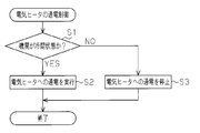
- FIG. 2 shows an execution procedure of energization control of the electric heater 19 in the present embodiment. This series of processing is repeatedly executed at predetermined intervals by the electronic control unit 50 during engine operation.
- step S1 it is first determined whether or not the engine is in a cold state (step S1).
- a predetermined temperature for example, 70 ° C.
- step S1 when it is determined that the engine is not in a cold state, that is, in a warm state (step S1: “NO”), the process proceeds to step S3, where energization of the electric heater 19 is stopped ( If the energization has already been stopped, the same stop is continued), and this series of processes is temporarily ended.
- the electronic control unit 50 executes idle rotation speed control in the following manner.
- the fuel injection amount is increased by increasing the fuel injection amount when the engine is cold when idle operation is performed compared to when the engine is warm. Like to do.
- the electronic control unit 50 has a rotational speed (first speed) higher than the idle rotational speed (third predetermined value N3) when the engine speed NE is warm. 2 predetermined value N2), the fuel injection mode from the fuel injection valve 18 is controlled.
- the second predetermined value N2 corresponds to the non-heating idle rotation speed.
- the electronic control unit 50 heats the fuel injected from the fuel injection valve 18 by the electric heater 19, the fuel is controlled so that the engine rotational speed NE becomes the first predetermined value N1 less than the second predetermined value N2.
- the fuel injection amount by the injection valve 18 is controlled.
- the electronic control unit 50 causes the electric heater 19 to reduce the fuel consumption of the engine when the fuel injected from the fuel injection valve 18 is heated by the electric heater 19 compared to when the fuel is not heated. And the fuel injection amount by the fuel injection valve 18 are controlled.
- FIG. 3 shows an execution procedure of idle rotation speed control in the present embodiment. This series of processing is repeatedly executed at predetermined intervals by the electronic control unit 50 during idle operation.
- step S11 it is first determined whether or not the engine is in a cold state (step S11).
- step S11: “NO” when the engine is not in the cold state but in the warm state, the process proceeds to step S12, where the target rotational speed Ntrg is set to the third predetermined value N3. Then, the process proceeds to step S15.
- step S11 when the engine is in the cold state in step S11 (step S11: “YES”), the process proceeds to step S13 to determine whether or not the fuel in the fuel injection valve 18 is heated. Specifically, when the electric heater 19 is energized, it is determined that the fuel in the fuel injection valve 18 is heated.
- step S13 if it is determined that the fuel is heated (step S13: “YES”), then, the target rotational speed Ntrg is set to a first predetermined value N1 (> N3) greater than the third predetermined value N3. Then, the process proceeds to step S15.
- step S13 when it is determined that the electric heater 19 is not energized due to a low charge state of the battery 42 and the fuel is not heated in step S13 (step S13: “NO”).
- the target rotational speed Ntrg is set to a second predetermined value N2 (> N1) larger than the first predetermined value N1, and then the process proceeds to step S15.
- step S15 the fuel injection amount Q is set so that the engine rotational speed NE becomes the target rotational speed Ntrg based on the deviation between the actual engine rotational speed NE and the set target rotational speed Ntrg. The process is temporarily terminated.
- the heated fuel is injected from the fuel injection valve 18. For this reason, the atomization of the fuel is promoted, and the fuel is prevented from adhering to the inner wall of the intake port 24.
- the amount of remaining fuel droplets in the cylinder 11 until combustion is started can be reduced, and the degree of premixing of fuel and air can be increased. Therefore, the number of PM particles in the exhaust, so-called PN, is preferably reduced.
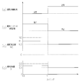
- item (a) shows the change in the warm-up state of the engine
- item (b) shows the change in the energization state of the electric heater 19
- item (c) shows the change in the engine rotational speed NE
- item (d ) Shows the transition of the fuel consumption S of the engine.
- the transition of each parameter when the fuel injected from the fuel injection valve 18 is heated by the electric heater 19 is indicated by a solid line
- the transition of each parameter when not heated is indicated by a one-dot chain line. Show.
- the electric heater 19 is energized to inject from the fuel injection valve 18.
- the fuel to be heated is heated.
- the engine speed NE is set to the first predetermined value N1.
- the fuel consumption amount S1 is smaller than the fuel consumption amount S2 when the fuel injected from the fuel injection valve 18 by the electric heater 19 is not heated.
- the engine speed NE is set to a third predetermined value N3.
- the heating mode by the electric heater 19 and the fuel injection amount Q by the fuel injection valve 18 are controlled so that the heating is not performed. Compared to the above, the fuel consumption S of the engine is reduced.
- the electronic control unit 50 controls the gasoline engine provided with the electric heater 19 that is built in the fuel injection valve 18 and heats the fuel inside the fuel injection valve 18. In addition, the fuel is heated by the electric heater 19 when the engine is cold. According to such a configuration, even if a filter for collecting PM is not provided in the exhaust passage 30, the number of PM particles in the exhaust, so-called PN, can be suitably reduced.
- the electric heater 19 is operated by electric power supplied from the battery 42.
- the battery 42 is configured to charge the electric power generated by the alternator 41.
- the fuel consumption S of the gasoline engine is reduced when the fuel injected from the fuel injection valve 18 is heated by the electric heater 19 as compared with the case where the fuel is not heated.
- the heating mode by the electric heater 19 and the fuel injection amount Q by the fuel injection valve 18 are controlled. According to such a configuration, when idle operation is performed when the engine is cold, the fuel consumption S can be accurately reduced while suppressing instability of the engine operation.
- so-called fuel cut is executed through the electronic control unit 50, which stops fuel injection by the fuel injection valve 18 when a predetermined fuel cut execution condition is satisfied during engine operation. Further, when a predetermined return condition is satisfied during execution of fuel cut, fuel cut return control for restarting fuel injection by the fuel injection valve 18 is executed.
- the predetermined fuel cut condition is satisfied when, for example, the accelerator operation amount ACCP is minimized (the operation amount is zero) when the engine rotational speed NE is equal to or higher than the predetermined rotational speed.
- the predetermined return condition is satisfied, for example, when the accelerator operation amount ACCP increases during execution of the fuel cut, or when the engine rotational speed NE becomes lower than the return rotational speed lower than the predetermined rotational speed.
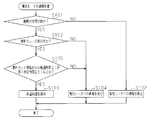
- FIG. 5 shows an execution procedure of energization control of the electric heater 19 in the present embodiment. This series of processing is repeatedly executed at predetermined intervals by the electronic control unit 50 during engine operation.
- step S101 it is first determined whether or not the engine is in a cold state (step S101).
- step S101 if it is determined that the engine is not in a cold state, that is, is in a warm state (step S101: “NO”), the process proceeds to step S102, and energization of the electric heater 19 is stopped. (If the energization has already been stopped, the same stop is continued), and this series of processes is once ended.
- step S101 determines whether or not a fuel cut is being performed.
- step S103 determines whether or not a fuel cut is being performed.
- step S104 the energization of the electric heater 19 is executed, and this series of processes is temporarily ended.
- step S102 if the fuel cut is being executed in step S103 (step S102: “NO”), the process proceeds to step S105, where the elapsed time ⁇ t from the start of the fuel cut is the first predetermined time ⁇ t1 ( In this embodiment, it is determined whether it is 5 seconds or more. As a result, when the elapsed time ⁇ t is less than the first predetermined time ⁇ t1 (step S0105: “NO”), the process proceeds to step S104, the energization of the electric heater 19 is executed, and this series of steps is performed. The process is temporarily terminated.
- step S105 when the elapsed time ⁇ t is equal to or longer than the first predetermined time ⁇ t1 (step S105: “YES”), a heat retaining process is then executed, and this series of processes is temporarily terminated.
- this heat retention process first, the energization to the electric heater 19 is stopped for a second predetermined time ⁇ t2 (10 seconds in the present embodiment), and then the electric heater 19 is applied for a third predetermined time ⁇ t3 (1 second in the present embodiment). The process of energizing is repeatedly performed.
- the electronic control unit 50 executes fuel cut return control in the following manner.
- the fuel injection amount is the fuel injection amount when the engine is warm (the third place) when compared under the condition that the other engine operating states are the same.
- the fuel injection amount is controlled so that the second predetermined amount Q2 is larger than the fixed amount Q3).
- the second predetermined amount Q2 corresponds to the unheated fuel amount.
- the fuel injection amount is less than the second predetermined amount Q2 when compared under the condition that the other engine operating states are the same.
- the fuel injection amount is controlled so as to be the first predetermined amount Q1.
- the heating mode and the fuel by the electric heater 19 are reduced so that the fuel consumption S of the engine is smaller than when the fuel is not heated.
- the fuel injection amount Q by the injection valve 18 is controlled.
- FIG. 6 shows the execution procedure of the fuel cut return control in this embodiment. This series of processing is repeatedly executed at predetermined intervals by the electronic control device 50 during execution of fuel cut.
- step S111 it is first determined whether or not a predetermined return condition is satisfied (step S111).
- step S111: “NO”) when the predetermined return condition is not satisfied (step S111: “NO”), this series of processes is temporarily ended in order to continue the fuel cut.
- step S111 if the predetermined return condition is satisfied (step S111: “YES”), the process proceeds to step S112, where it is determined whether or not the engine is in a cold state. If it is not in the cold state (step S112: “NO”), the target fuel injection amount Qtrg is set to the third predetermined amount Q3, and then the process proceeds to step S116.
- step S112 when the engine is in a cold state (step S112: “YES”), the process proceeds to step S114, and it is determined whether or not the fuel in the fuel injection valve 18 is heated.
- step S114 if it is determined that the fuel is heated (step S114: “YES”), the process proceeds to step S115, and the target fuel injection amount Qtrg is set to the first predetermined amount Q1. Then, the process proceeds to step S116.
- step S114 when it is determined that the electric heater 19 is not energized due to a low charge state of the battery 42 and the fuel is not heated in step S114 (step S114: “NO”).
- step S117 the target fuel injection amount Qtrg is set to a second predetermined amount Q2 that is larger than the first predetermined amount Q1. Then, the process proceeds to step S116.
- step S116 the fuel injection valve 18 is driven based on the set target fuel injection amount Qtrg, and this series of processes is temporarily terminated.
- item (a) is a transition of the warm-up state of the engine
- item (b) is a transition of the fuel cut execution state
- item (c) is a transition of the energization state of the electric heater 19
- item (d ) Shows the transition of the temperature TF of the fuel in the fuel injection valve 18.
- a predetermined fuel cut execution condition is established at timing t11 when the engine is in a cold state and energization of the electric heater 19 is being executed. Fuel cut is executed. Thereafter, as shown in the item (c), energization of the electric heater 19 is continued until the timing t12, that is, until the elapsed time ⁇ t from the timing t11 reaches the first predetermined time ⁇ t1. Thereby, as shown in the item (d), the temperature TF of the fuel in the fuel injection valve 18 gradually increases.
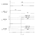
- item (a) is the change in the warm-up state of the engine
- item (b) is the change in the fuel cut execution state
- item (c) is the change in fuel injection amount Q
- item (d) is the fuel.
- the transition of consumption S is shown.
- the transition of each parameter when the fuel injected from the fuel injection valve 18 is heated by the electric heater 19 is indicated by a solid line
- the transition of each parameter when not heated is indicated by a one-dot chain line. Show.
- the transition of each parameter when the engine is in a warm state is indicated by a two-dot chain line.
- a predetermined return condition is established at a timing t21 when the engine is in a cold state, and accordingly, the fuel injection valve 18 uses the fuel injection valve 18 to stop and return. Fuel injection is resumed.
- the fuel injection amount Q is set to the first predetermined amount Q1.
- the fuel consumption amount S1 is smaller than the fuel consumption amount S2 when the fuel injected from the fuel injection valve 18 by the electric heater 19 is not heated.
- the fuel injection from the fuel injection valve 18 is resumed to recover from the fuel cut when the engine is cold, the fuel is heated by the electric heater 19 so that the atomization of the fuel is promoted. . For this reason, it is possible to suppress the shortage of the engine output without increasing the fuel injection amount Q to the second predetermined amount Q2 (non-heating fuel amount). Further, the fuel consumption S of the engine can be reduced as compared with the configuration in which the fuel injected from the fuel injection valve 18 is heated by the electric heater 19 and the fuel injection amount Q is set to the second predetermined amount Q2. Become.
- the heating mode by the electric heater 19 and the fuel injection amount Q by the fuel injection valve 18 are controlled so that the heating is not performed. Compared to the above, the fuel consumption S of the engine is reduced.
- the following effects (4) and (5) are newly obtained in addition to the effects (1) to (3) of the first embodiment. Be able to.
- FIG. 9 shows a schematic configuration of the engine of the present embodiment and the electronic control unit 50 that controls the engine.
- FIG. 9 shows a sectional structure of one cylinder 11.
- the engine of this embodiment basically has the same configuration as the engines of the first and second embodiments.
- the engine of the present embodiment has a fuel injection valve (hereinafter referred to as direct injection) that directly injects fuel into the cylinder 11 in addition to a fuel injection valve (hereinafter referred to as port-type fuel injection valve 18) that injects fuel into the intake port 24.
- An injection type fuel injection valve 68) is also provided.
- the electric heater 19 is incorporated only in the port type fuel injection valve 18 and is not incorporated in the direct injection type fuel injection valve 68.
- a second supply passage 67c branches from a portion downstream of the fuel pump 17b, and the second supply passage 67c is connected to the direct injection fuel injection valve 68.
- a high pressure fuel pump 67b for further pressurizing the fuel pressurized by the fuel pump 17b is provided in the middle of the second supply passage 67c.
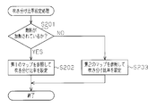
- step S201 it is first determined whether or not the fuel in the port type fuel injection valve 18 is heated.
- step S201 when the fuel is heated (step S201: “YES”), next, the process proceeds to step S202, the blowing ratio is set with reference to the first map, and this series of processing is temporarily performed. finish.
- step S201 if the fuel is not heated (step S201: “NO”), the process proceeds to step S203, the blowing ratio is set with reference to the second map, and this series of processes is temporarily terminated. To do.
- These maps are two-dimensional maps in which the blowing ratio is defined by the engine speed NE and the engine load KL.
- the magnitude of the blowing ratio Rp of the port-type fuel injection valve 18 at the same engine speed NE and the same engine load KL is larger in the first map than in the second map. That is, when the fuel injected from the port type fuel injection valve 18 is heated by the electric heater 19, the ratio of the fuel injected from the fuel injection valve 18 is made larger than when the fuel is not heated.
- the ratio of the fuel injected from the port type fuel injection valve 18, that is, the fuel that is heated by the electric heater 19 to promote atomization is increased. Further, the ratio of the fuel injected from the direct injection fuel injection valve 68, that is, the fuel that is not heated and is difficult to be atomized is reduced. Thereby, although the amount of fuel injected from the port type fuel injection valve 18 is increased, the atomization of the fuel is promoted, so that the amount of fuel adhering to the inner wall of the intake port 24 is reduced.
- the engine is provided with both a port type fuel injection valve 18 that injects fuel into the intake port 24 and a direct injection type fuel injection valve 68 that directly injects fuel into the cylinder 11.
- the electric heater 19 heats only the fuel injected from the port type fuel injection valve 18.
- the ratio of the fuel injected from the fuel injection valve 18 is made larger than when the fuel is not heated. According to such a configuration, the total amount of fuel adhering to the inner wall of the intake port 24 and the inner wall of the cylinder 11 can be reduced, and the number of PM particles (PN) in the exhaust gas can be accurately reduced. .
- control apparatus of the gasoline engine which concerns on this invention is not limited to the structure illustrated in the said embodiment, For example, it can also implement as the following forms which changed this suitably.
- the mode for determining whether or not the engine is in a cold state is not limited to those exemplified in the above embodiments, and it may be determined based on the temperature of the lubricating oil or the intake air temperature of the engine. .
- step S11 in FIG. 3 it is determined that the fuel in the fuel injection valve 18 is heated when the electric heater 19 is energized (see, for example, step S11 in FIG. 3).
- a sensor for detecting the temperature in the fuel injection valve may be provided, and it may be determined whether the fuel in the fuel injection valve is heated based on the detection result of the sensor. In this case, it becomes possible to more accurately determine whether or not the fuel in the fuel injection valve is heated.
- the present invention is applied to the engine having only the port type fuel injection valve 18, but instead, the present invention is applied to an engine having only the direct injection type fuel injection valve. You may make it do.
- the energization control, idle rotation speed control, and fuel cut return control of the electric heater 19 exemplified in the first and second embodiments may be used.
- the configuration in which the electric heater 19 is incorporated only in the port type fuel injection valve 18 in the engine including both the port type fuel injection valve 18 and the direct injection type fuel injection valve 68 is exemplified.
- the present invention is not limited to this, and an electric heater may be incorporated only in the direct injection fuel injection valve.
- it can also be set as the structure by which an electric heater is incorporated in both a port type fuel injection valve and a direct injection type fuel injection valve.
- the fuel consumption S of the gasoline engine is reduced so as to be smaller than when the fuel is not heated. It is desirable to control the heating mode by the heater 19 and the fuel injection amount Q by the fuel injection valve 18.
- the present invention includes one in which the fuel consumption S of the gasoline engine is larger when the fuel injected from the fuel injection valve 18 is heated by the electric heater 19 than when the fuel is not heated.
- the electric heater 19 is illustrated as being built in the fuel injection valve 18, but the heating device according to the present invention is not limited to this.
- a pipe for supplying fuel to the fuel injection valve may be heated.
- any electric heating device may be used as long as it heats the fuel in a portion upstream of the nozzle hole of the fuel injection valve in the fuel supply system.
- the present invention can also be embodied as a gasoline engine control device for a hybrid vehicle provided with an electric motor in addition to a gasoline engine as a vehicle drive source.
- the present invention may be applied when starting fuel injection to start the engine during EV traveling. That is, when starting the fuel injection from the fuel injection valve when the engine is cold, the fuel injection valve is heated if the fuel injected from the fuel injection valve is heated by the heating device if the other engine operating states are the same.
- the amount of fuel injected from the fuel may be less than the non-heating time fuel amount.
Landscapes
- Engineering & Computer Science (AREA)
- Chemical & Material Sciences (AREA)
- Combustion & Propulsion (AREA)
- Mechanical Engineering (AREA)
- General Engineering & Computer Science (AREA)
- Electrical Control Of Air Or Fuel Supplied To Internal-Combustion Engine (AREA)
- Combined Controls Of Internal Combustion Engines (AREA)
- Fuel-Injection Apparatus (AREA)
- Control Of Vehicle Engines Or Engines For Specific Uses (AREA)
Abstract
Description
Claims (7)
- 燃料供給系において燃料噴射弁の噴孔よりも上流側の部位の燃料を加熱する電気式の加熱装置を備えるガソリン機関を制御する制御装置であって、
機関冷間時には前記加熱装置により当該燃料を加熱させる、ガソリン機関の制御装置。 - 請求項1に記載のガソリン機関の制御装置において、
機関冷間時においてアイドル運転がなされているとき、前記加熱装置により前記燃料噴射弁から噴射される燃料を加熱する場合における機関回転速度が、前記加熱装置により前記燃料噴射弁から噴射される燃料を加熱しない場合における機関回転速度未満となるように前記燃料噴射弁による燃料噴射量を制御する、ガソリン機関の制御装置。 - 請求項2に記載のガソリン機関の制御装置において、
前記加熱装置はバッテリから供給される電力により作動し、
前記バッテリは機関駆動式の発電機によって発電された電力を充電するように構成され、
機関冷間時においてアイドル運転がなされているとき、前記加熱装置により前記燃料噴射弁から噴射される燃料を加熱する場合には加熱しない場合に比べてガソリン機関の燃料消費量が少なくなるように、前記加熱装置による加熱態様と前記燃料噴射弁による燃料噴射量とを制御する、ガソリン機関の制御装置。 - 請求項1~請求項3のいずれか一項に記載のガソリン機関の制御装置において、
機関冷間時において前記燃料噴射弁からの燃料噴射を開始或いは再開する際、前記加熱装置により前記燃料噴射弁から噴射される燃料を加熱する場合において前記燃料噴射弁から噴射される燃料量が、他の機関運転状態が同一であるとの条件で比較したときに前記加熱装置により前記燃料噴射弁から噴射される燃料を加熱しない場合において前記燃料噴射弁から噴射される燃料量未満となるように、前記燃料噴射量を制御する、ガソリン機関の制御装置。 - 請求項4に記載のガソリン機関の制御装置において、
前記加熱装置はバッテリから供給される電力により作動し、
前記バッテリは機関駆動式の発電機によって発電された電力を充電するように構成され、
機関冷間時において前記燃料噴射弁からの燃料噴射を開始或いは再開する際、前記加熱装置により前記燃料噴射弁から噴射される燃料を加熱する場合には加熱しない場合に比べてガソリン機関の燃料消費量が少なくなるように、前記加熱装置による加熱態様と前記燃料噴射弁による燃料噴射量とを制御する、ガソリン機関の制御装置。 - 請求項1~請求項5のいずれか一項に記載のガソリン機関の制御装置において、
ガソリン機関は吸気ポート内に燃料を噴射するポート式燃料噴射弁と気筒内に燃料を直接噴射する直噴式燃料噴射弁との双方を備え、
前記加熱装置は前記ポート式燃料噴射弁及び直噴式燃料噴射弁のいずれか一方の燃料噴射弁から噴射される燃料を加熱するように構成され、
前記加熱装置により前記一方の燃料噴射弁から噴射される燃料を加熱する場合には加熱しない場合に比べて前記一方の燃料噴射弁から噴射される燃料の割合を大きくする、ガソリン機関の制御装置。 - 請求項1~請求項6のいずれか一項に記載のガソリン機関の制御装置において、
機関温度が所定温度以下であるときに機関冷間時であると判断する、ガソリン機関の制御装置。
Priority Applications (5)
| Application Number | Priority Date | Filing Date | Title |
|---|---|---|---|
| JP2014509941A JP5794386B2 (ja) | 2012-04-11 | 2012-04-11 | ガソリン機関の制御装置 |
| EP12874021.4A EP2837806B1 (en) | 2012-04-11 | 2012-04-11 | Control device for gasoline engine |
| CN201280072246.9A CN104204477B (zh) | 2012-04-11 | 汽油动力机的控制装置 | |
| PCT/JP2012/059861 WO2013153627A1 (ja) | 2012-04-11 | 2012-04-11 | ガソリン機関の制御装置 |
| US14/390,417 US9399971B2 (en) | 2012-04-11 | 2012-04-11 | Control device for gasoline engine |
Applications Claiming Priority (1)
| Application Number | Priority Date | Filing Date | Title |
|---|---|---|---|
| PCT/JP2012/059861 WO2013153627A1 (ja) | 2012-04-11 | 2012-04-11 | ガソリン機関の制御装置 |
Publications (1)
| Publication Number | Publication Date |
|---|---|
| WO2013153627A1 true WO2013153627A1 (ja) | 2013-10-17 |
Family
ID=49327234
Family Applications (1)
| Application Number | Title | Priority Date | Filing Date |
|---|---|---|---|
| PCT/JP2012/059861 Ceased WO2013153627A1 (ja) | 2012-04-11 | 2012-04-11 | ガソリン機関の制御装置 |
Country Status (4)
| Country | Link |
|---|---|
| US (1) | US9399971B2 (ja) |
| EP (1) | EP2837806B1 (ja) |
| JP (1) | JP5794386B2 (ja) |
| WO (1) | WO2013153627A1 (ja) |
Cited By (2)
| Publication number | Priority date | Publication date | Assignee | Title |
|---|---|---|---|---|
| WO2016042700A1 (ja) * | 2014-09-16 | 2016-03-24 | 株式会社デンソー | 内燃機関の燃料供給制御装置 |
| JP2019210892A (ja) * | 2018-06-07 | 2019-12-12 | 川崎重工業株式会社 | エンジン |
Families Citing this family (5)
| Publication number | Priority date | Publication date | Assignee | Title |
|---|---|---|---|---|
| GB201611055D0 (en) * | 2016-06-24 | 2016-08-10 | Mclaren Automotive Ltd | Fuel heating |
| JP2019100197A (ja) * | 2017-11-29 | 2019-06-24 | 本田技研工業株式会社 | 燃料噴射制御装置およびエンジンシステム |
| US12350764B2 (en) * | 2018-09-28 | 2025-07-08 | Illinois Tool Works Inc. | Methods and apparatus for hybrid-diesel engine block heater |
| DE102018217589B4 (de) * | 2018-10-15 | 2020-12-17 | Vitesco Technologies GmbH | Kraftstoffinjektor, und Verfahren zum Betreiben eines Kraftstoffeinspritzsystems für eine Brennkraftmaschine |
| JP2022030578A (ja) * | 2020-08-07 | 2022-02-18 | 株式会社アイシン | 燃料加熱装置 |
Citations (5)
| Publication number | Priority date | Publication date | Assignee | Title |
|---|---|---|---|---|
| JPH05149216A (ja) * | 1991-11-22 | 1993-06-15 | Hitachi Ltd | 電子制御燃料噴射装置 |
| JPH11117816A (ja) * | 1997-10-15 | 1999-04-27 | Yamaha Motor Co Ltd | 4サイクルエンジンの吸気装置 |
| JP2005054615A (ja) * | 2003-08-08 | 2005-03-03 | Hitachi Ltd | 筒内噴射エンジンの燃料供給システム及び燃料供給方法 |
| JP2009191649A (ja) * | 2008-02-12 | 2009-08-27 | Toyota Motor Corp | 内燃機関の制御装置 |
| JP2009216005A (ja) | 2008-03-11 | 2009-09-24 | Toyota Motor Corp | 内燃機関 |
Family Cites Families (12)
| Publication number | Priority date | Publication date | Assignee | Title |
|---|---|---|---|---|
| JPH05195887A (ja) * | 1992-01-16 | 1993-08-03 | Hitachi Ltd | エンジンの燃料供給装置、燃料噴射弁及び燃料気化装置 |
| US5894832A (en) * | 1996-07-12 | 1999-04-20 | Hitachi America, Ltd., Research And Development Division | Cold start engine control apparatus and method |
| JPH10238424A (ja) * | 1997-02-21 | 1998-09-08 | Denso Corp | 燃料噴射装置 |
| EP1469178A3 (en) * | 1997-05-26 | 2005-06-08 | Nissan Motor Co., Ltd. | Engine idle speed controller |
| EP1138901A3 (en) * | 2000-03-29 | 2004-04-07 | Hitachi, Ltd. | Fuel supply system for internal combustion engine |
| US7249596B2 (en) * | 2002-03-22 | 2007-07-31 | Philip Morris Usa Inc. | Fuel system for an internal combustion engine and method for controlling same |
| US7481205B2 (en) * | 2004-11-03 | 2009-01-27 | Philip Morris Usa Inc. | High frequency vaporized fuel injector |
| US7677468B2 (en) * | 2006-03-27 | 2010-03-16 | Continental Automotive Systems Us, Inc. | Inductive heated injector using additional coil |
| JP2010038000A (ja) | 2008-08-01 | 2010-02-18 | Toyota Motor Corp | 燃料供給装置 |
| JP5549250B2 (ja) | 2010-02-05 | 2014-07-16 | トヨタ自動車株式会社 | 内燃機関の制御装置 |
| FR2962170B1 (fr) | 2010-06-30 | 2013-05-10 | Valeo Sys Controle Moteur Sas | Procede et dispositif de controle d'un moteur, ensemble d'un tel dispositif et d'un circuit d'alimentation en carburant du moteur |
| US9476393B2 (en) * | 2013-03-19 | 2016-10-25 | Delphi Technologies, Inc. | Heated fuel injector |
-
2012
- 2012-04-11 JP JP2014509941A patent/JP5794386B2/ja not_active Expired - Fee Related
- 2012-04-11 US US14/390,417 patent/US9399971B2/en not_active Expired - Fee Related
- 2012-04-11 WO PCT/JP2012/059861 patent/WO2013153627A1/ja not_active Ceased
- 2012-04-11 EP EP12874021.4A patent/EP2837806B1/en active Active
Patent Citations (5)
| Publication number | Priority date | Publication date | Assignee | Title |
|---|---|---|---|---|
| JPH05149216A (ja) * | 1991-11-22 | 1993-06-15 | Hitachi Ltd | 電子制御燃料噴射装置 |
| JPH11117816A (ja) * | 1997-10-15 | 1999-04-27 | Yamaha Motor Co Ltd | 4サイクルエンジンの吸気装置 |
| JP2005054615A (ja) * | 2003-08-08 | 2005-03-03 | Hitachi Ltd | 筒内噴射エンジンの燃料供給システム及び燃料供給方法 |
| JP2009191649A (ja) * | 2008-02-12 | 2009-08-27 | Toyota Motor Corp | 内燃機関の制御装置 |
| JP2009216005A (ja) | 2008-03-11 | 2009-09-24 | Toyota Motor Corp | 内燃機関 |
Cited By (2)
| Publication number | Priority date | Publication date | Assignee | Title |
|---|---|---|---|---|
| WO2016042700A1 (ja) * | 2014-09-16 | 2016-03-24 | 株式会社デンソー | 内燃機関の燃料供給制御装置 |
| JP2019210892A (ja) * | 2018-06-07 | 2019-12-12 | 川崎重工業株式会社 | エンジン |
Also Published As
| Publication number | Publication date |
|---|---|
| US9399971B2 (en) | 2016-07-26 |
| JP5794386B2 (ja) | 2015-10-14 |
| US20150167600A1 (en) | 2015-06-18 |
| EP2837806A4 (en) | 2018-01-03 |
| EP2837806A1 (en) | 2015-02-18 |
| CN104204477A (zh) | 2014-12-10 |
| JPWO2013153627A1 (ja) | 2015-12-17 |
| EP2837806B1 (en) | 2019-09-25 |
Similar Documents
| Publication | Publication Date | Title |
|---|---|---|
| JP5794386B2 (ja) | ガソリン機関の制御装置 | |
| RU2622344C2 (ru) | Способ запуска двигателя (варианты) и система запуска двигателя, присоединенного к трансмиссии | |
| JP6003936B2 (ja) | 内燃機関の制御装置 | |
| KR20110008255A (ko) | 자동 엔진 컷오프 및 스타팅 시스템에 의해 내연기관을 제어하기 위한 방법 및 장치 | |
| US11313304B2 (en) | Heater energization control device | |
| JP2010037968A (ja) | 内燃機関の燃料噴射制御装置 | |
| CN101142399A (zh) | 用于内燃机的燃料供应设备 | |
| CN113482830A (zh) | 一种减少发动机湿壁效应的控制方法以及控制装置 | |
| US10781758B2 (en) | Control device for internal combustion engine | |
| RU2711891C1 (ru) | Система (варианты) управления двигателем с датчиком выхлопных газов | |
| JP2008232007A (ja) | 内燃機関の始動制御装置 | |
| JP5392419B2 (ja) | 内燃機関の燃料供給装置 | |
| JP7144373B2 (ja) | 内燃機関の燃料噴射制御装置 | |
| JP2016183583A (ja) | 内燃機関の制御装置 | |
| US10393053B2 (en) | Fuel injector of internal combustion engine and fuel injection method thereof | |
| JP6752178B2 (ja) | エンジン回転数制御装置 | |
| CN104204477B (zh) | 汽油动力机的控制装置 | |
| JP4450324B2 (ja) | 内燃機関の始動制御装置 | |
| JP2011208560A (ja) | アイドルストップ機能付き筒内噴射エンジンの燃料供給制御装置 | |
| JP5672930B2 (ja) | 内燃機関の制御装置 | |
| JP2009057865A (ja) | 燃料噴射制御装置及び燃料噴射システム | |
| JP5760695B2 (ja) | 蓄圧式燃料噴射装置 | |
| JP2006194110A (ja) | 内燃機関の燃料供給装置の制御方法 | |
| JP2014015907A (ja) | 内燃機関の燃料噴射制御装置 | |
| JP2008232046A (ja) | 筒内噴射式の燃料噴射制御装置及びエンジン情報取得装置及びエンジン制御システム |
Legal Events
| Date | Code | Title | Description |
|---|---|---|---|
| 121 | Ep: the epo has been informed by wipo that ep was designated in this application |
Ref document number: 12874021 Country of ref document: EP Kind code of ref document: A1 |
|
| ENP | Entry into the national phase |
Ref document number: 2014509941 Country of ref document: JP Kind code of ref document: A |
|
| WWE | Wipo information: entry into national phase |
Ref document number: 14390417 Country of ref document: US |
|
| NENP | Non-entry into the national phase |
Ref country code: DE |
|
| WWE | Wipo information: entry into national phase |
Ref document number: 2012874021 Country of ref document: EP |