WO2013153903A1 - 識別媒体 - Google Patents
識別媒体 Download PDFInfo
- Publication number
- WO2013153903A1 WO2013153903A1 PCT/JP2013/057170 JP2013057170W WO2013153903A1 WO 2013153903 A1 WO2013153903 A1 WO 2013153903A1 JP 2013057170 W JP2013057170 W JP 2013057170W WO 2013153903 A1 WO2013153903 A1 WO 2013153903A1
- Authority
- WO
- WIPO (PCT)
- Prior art keywords
- identification medium
- liquid crystal
- cholesteric liquid
- support
- layer
- Prior art date
- Legal status (The legal status is an assumption and is not a legal conclusion. Google has not performed a legal analysis and makes no representation as to the accuracy of the status listed.)
- Ceased
Links
Images


Classifications
-
- B—PERFORMING OPERATIONS; TRANSPORTING
- B42—BOOKBINDING; ALBUMS; FILES; SPECIAL PRINTED MATTER
- B42D—BOOKS; BOOK COVERS; LOOSE LEAVES; PRINTED MATTER CHARACTERISED BY IDENTIFICATION OR SECURITY FEATURES; PRINTED MATTER OF SPECIAL FORMAT OR STYLE NOT OTHERWISE PROVIDED FOR; DEVICES FOR USE THEREWITH AND NOT OTHERWISE PROVIDED FOR; MOVABLE-STRIP WRITING OR READING APPARATUS
- B42D25/00—Information-bearing cards or sheet-like structures characterised by identification or security features; Manufacture thereof
- B42D25/30—Identification or security features, e.g. for preventing forgery
- B42D25/328—Diffraction gratings; Holograms
-
- B—PERFORMING OPERATIONS; TRANSPORTING
- B42—BOOKBINDING; ALBUMS; FILES; SPECIAL PRINTED MATTER
- B42D—BOOKS; BOOK COVERS; LOOSE LEAVES; PRINTED MATTER CHARACTERISED BY IDENTIFICATION OR SECURITY FEATURES; PRINTED MATTER OF SPECIAL FORMAT OR STYLE NOT OTHERWISE PROVIDED FOR; DEVICES FOR USE THEREWITH AND NOT OTHERWISE PROVIDED FOR; MOVABLE-STRIP WRITING OR READING APPARATUS
- B42D25/00—Information-bearing cards or sheet-like structures characterised by identification or security features; Manufacture thereof
- B42D25/30—Identification or security features, e.g. for preventing forgery
- B42D25/324—Reliefs
-
- B—PERFORMING OPERATIONS; TRANSPORTING
- B42—BOOKBINDING; ALBUMS; FILES; SPECIAL PRINTED MATTER
- B42D—BOOKS; BOOK COVERS; LOOSE LEAVES; PRINTED MATTER CHARACTERISED BY IDENTIFICATION OR SECURITY FEATURES; PRINTED MATTER OF SPECIAL FORMAT OR STYLE NOT OTHERWISE PROVIDED FOR; DEVICES FOR USE THEREWITH AND NOT OTHERWISE PROVIDED FOR; MOVABLE-STRIP WRITING OR READING APPARATUS
- B42D25/00—Information-bearing cards or sheet-like structures characterised by identification or security features; Manufacture thereof
- B42D25/30—Identification or security features, e.g. for preventing forgery
- B42D25/36—Identification or security features, e.g. for preventing forgery comprising special materials
- B42D25/364—Liquid crystals
-
- B—PERFORMING OPERATIONS; TRANSPORTING
- B42—BOOKBINDING; ALBUMS; FILES; SPECIAL PRINTED MATTER
- B42D—BOOKS; BOOK COVERS; LOOSE LEAVES; PRINTED MATTER CHARACTERISED BY IDENTIFICATION OR SECURITY FEATURES; PRINTED MATTER OF SPECIAL FORMAT OR STYLE NOT OTHERWISE PROVIDED FOR; DEVICES FOR USE THEREWITH AND NOT OTHERWISE PROVIDED FOR; MOVABLE-STRIP WRITING OR READING APPARATUS
- B42D25/00—Information-bearing cards or sheet-like structures characterised by identification or security features; Manufacture thereof
- B42D25/40—Manufacture
- B42D25/405—Marking
- B42D25/425—Marking by deformation, e.g. embossing
-
- G—PHYSICS
- G02—OPTICS
- G02F—OPTICAL DEVICES OR ARRANGEMENTS FOR THE CONTROL OF LIGHT BY MODIFICATION OF THE OPTICAL PROPERTIES OF THE MEDIA OF THE ELEMENTS INVOLVED THEREIN; NON-LINEAR OPTICS; FREQUENCY-CHANGING OF LIGHT; OPTICAL LOGIC ELEMENTS; OPTICAL ANALOGUE/DIGITAL CONVERTERS
- G02F1/00—Devices or arrangements for the control of the intensity, colour, phase, polarisation or direction of light arriving from an independent light source, e.g. switching, gating or modulating; Non-linear optics
- G02F1/0009—Materials therefor
- G02F1/0045—Liquid crystals characterised by their physical properties
-
- G—PHYSICS
- G02—OPTICS
- G02F—OPTICAL DEVICES OR ARRANGEMENTS FOR THE CONTROL OF LIGHT BY MODIFICATION OF THE OPTICAL PROPERTIES OF THE MEDIA OF THE ELEMENTS INVOLVED THEREIN; NON-LINEAR OPTICS; FREQUENCY-CHANGING OF LIGHT; OPTICAL LOGIC ELEMENTS; OPTICAL ANALOGUE/DIGITAL CONVERTERS
- G02F1/00—Devices or arrangements for the control of the intensity, colour, phase, polarisation or direction of light arriving from an independent light source, e.g. switching, gating or modulating; Non-linear optics
- G02F1/01—Devices or arrangements for the control of the intensity, colour, phase, polarisation or direction of light arriving from an independent light source, e.g. switching, gating or modulating; Non-linear optics for the control of the intensity, phase, polarisation or colour
- G02F1/13—Devices or arrangements for the control of the intensity, colour, phase, polarisation or direction of light arriving from an independent light source, e.g. switching, gating or modulating; Non-linear optics for the control of the intensity, phase, polarisation or colour based on liquid crystals, e.g. single liquid crystal display cells
- G02F1/133—Constructional arrangements; Operation of liquid crystal cells; Circuit arrangements
- G02F1/1333—Constructional arrangements; Manufacturing methods
- G02F1/133305—Flexible substrates, e.g. plastics, organic film
-
- G—PHYSICS
- G02—OPTICS
- G02F—OPTICAL DEVICES OR ARRANGEMENTS FOR THE CONTROL OF LIGHT BY MODIFICATION OF THE OPTICAL PROPERTIES OF THE MEDIA OF THE ELEMENTS INVOLVED THEREIN; NON-LINEAR OPTICS; FREQUENCY-CHANGING OF LIGHT; OPTICAL LOGIC ELEMENTS; OPTICAL ANALOGUE/DIGITAL CONVERTERS
- G02F1/00—Devices or arrangements for the control of the intensity, colour, phase, polarisation or direction of light arriving from an independent light source, e.g. switching, gating or modulating; Non-linear optics
- G02F1/01—Devices or arrangements for the control of the intensity, colour, phase, polarisation or direction of light arriving from an independent light source, e.g. switching, gating or modulating; Non-linear optics for the control of the intensity, phase, polarisation or colour
- G02F1/13—Devices or arrangements for the control of the intensity, colour, phase, polarisation or direction of light arriving from an independent light source, e.g. switching, gating or modulating; Non-linear optics for the control of the intensity, phase, polarisation or colour based on liquid crystals, e.g. single liquid crystal display cells
- G02F1/133—Constructional arrangements; Operation of liquid crystal cells; Circuit arrangements
- G02F1/1333—Constructional arrangements; Manufacturing methods
- G02F1/1335—Structural association of cells with optical devices, e.g. polarisers or reflectors
- G02F1/133528—Polarisers
-
- G—PHYSICS
- G03—PHOTOGRAPHY; CINEMATOGRAPHY; ANALOGOUS TECHNIQUES USING WAVES OTHER THAN OPTICAL WAVES; ELECTROGRAPHY; HOLOGRAPHY
- G03H—HOLOGRAPHIC PROCESSES OR APPARATUS
- G03H1/00—Holographic processes or apparatus using light, infrared or ultraviolet waves for obtaining holograms or for obtaining an image from them; Details peculiar thereto
-
- G—PHYSICS
- G03—PHOTOGRAPHY; CINEMATOGRAPHY; ANALOGOUS TECHNIQUES USING WAVES OTHER THAN OPTICAL WAVES; ELECTROGRAPHY; HOLOGRAPHY
- G03H—HOLOGRAPHIC PROCESSES OR APPARATUS
- G03H1/00—Holographic processes or apparatus using light, infrared or ultraviolet waves for obtaining holograms or for obtaining an image from them; Details peculiar thereto
- G03H1/02—Details of features involved during the holographic process; Replication of holograms without interference recording
- G03H1/024—Hologram nature or properties
- G03H1/0244—Surface relief holograms
-
- G—PHYSICS
- G03—PHOTOGRAPHY; CINEMATOGRAPHY; ANALOGOUS TECHNIQUES USING WAVES OTHER THAN OPTICAL WAVES; ELECTROGRAPHY; HOLOGRAPHY
- G03H—HOLOGRAPHIC PROCESSES OR APPARATUS
- G03H1/00—Holographic processes or apparatus using light, infrared or ultraviolet waves for obtaining holograms or for obtaining an image from them; Details peculiar thereto
- G03H1/02—Details of features involved during the holographic process; Replication of holograms without interference recording
- G03H1/0252—Laminate comprising a hologram layer
-
- G—PHYSICS
- G03—PHOTOGRAPHY; CINEMATOGRAPHY; ANALOGOUS TECHNIQUES USING WAVES OTHER THAN OPTICAL WAVES; ELECTROGRAPHY; HOLOGRAPHY
- G03H—HOLOGRAPHIC PROCESSES OR APPARATUS
- G03H1/00—Holographic processes or apparatus using light, infrared or ultraviolet waves for obtaining holograms or for obtaining an image from them; Details peculiar thereto
- G03H1/02—Details of features involved during the holographic process; Replication of holograms without interference recording
- G03H1/0272—Substrate bearing the hologram
-
- A—HUMAN NECESSITIES
- A41—WEARING APPAREL
- A41D—OUTERWEAR; PROTECTIVE GARMENTS; ACCESSORIES
- A41D27/00—Details of garments or of their making
- A41D27/08—Trimmings; Ornaments
- A41D27/085—Luminous ornaments
-
- G—PHYSICS
- G02—OPTICS
- G02F—OPTICAL DEVICES OR ARRANGEMENTS FOR THE CONTROL OF LIGHT BY MODIFICATION OF THE OPTICAL PROPERTIES OF THE MEDIA OF THE ELEMENTS INVOLVED THEREIN; NON-LINEAR OPTICS; FREQUENCY-CHANGING OF LIGHT; OPTICAL LOGIC ELEMENTS; OPTICAL ANALOGUE/DIGITAL CONVERTERS
- G02F1/00—Devices or arrangements for the control of the intensity, colour, phase, polarisation or direction of light arriving from an independent light source, e.g. switching, gating or modulating; Non-linear optics
- G02F1/01—Devices or arrangements for the control of the intensity, colour, phase, polarisation or direction of light arriving from an independent light source, e.g. switching, gating or modulating; Non-linear optics for the control of the intensity, phase, polarisation or colour
- G02F1/13—Devices or arrangements for the control of the intensity, colour, phase, polarisation or direction of light arriving from an independent light source, e.g. switching, gating or modulating; Non-linear optics for the control of the intensity, phase, polarisation or colour based on liquid crystals, e.g. single liquid crystal display cells
- G02F1/133—Constructional arrangements; Operation of liquid crystal cells; Circuit arrangements
- G02F1/1333—Constructional arrangements; Manufacturing methods
- G02F1/1335—Structural association of cells with optical devices, e.g. polarisers or reflectors
- G02F1/133528—Polarisers
- G02F1/133541—Circular polarisers
-
- G—PHYSICS
- G03—PHOTOGRAPHY; CINEMATOGRAPHY; ANALOGOUS TECHNIQUES USING WAVES OTHER THAN OPTICAL WAVES; ELECTROGRAPHY; HOLOGRAPHY
- G03H—HOLOGRAPHIC PROCESSES OR APPARATUS
- G03H1/00—Holographic processes or apparatus using light, infrared or ultraviolet waves for obtaining holograms or for obtaining an image from them; Details peculiar thereto
- G03H1/0005—Adaptation of holography to specific applications
- G03H1/0011—Adaptation of holography to specific applications for security or authentication
-
- G—PHYSICS
- G03—PHOTOGRAPHY; CINEMATOGRAPHY; ANALOGOUS TECHNIQUES USING WAVES OTHER THAN OPTICAL WAVES; ELECTROGRAPHY; HOLOGRAPHY
- G03H—HOLOGRAPHIC PROCESSES OR APPARATUS
- G03H2222/00—Light sources or light beam properties
- G03H2222/31—Polarised light
-
- G—PHYSICS
- G03—PHOTOGRAPHY; CINEMATOGRAPHY; ANALOGOUS TECHNIQUES USING WAVES OTHER THAN OPTICAL WAVES; ELECTROGRAPHY; HOLOGRAPHY
- G03H—HOLOGRAPHIC PROCESSES OR APPARATUS
- G03H2250/00—Laminate comprising a hologram layer
- G03H2250/14—Forming layer onto which a surface relief hologram is formed
-
- G—PHYSICS
- G03—PHOTOGRAPHY; CINEMATOGRAPHY; ANALOGOUS TECHNIQUES USING WAVES OTHER THAN OPTICAL WAVES; ELECTROGRAPHY; HOLOGRAPHY
- G03H—HOLOGRAPHIC PROCESSES OR APPARATUS
- G03H2250/00—Laminate comprising a hologram layer
- G03H2250/34—Colour layer
-
- G—PHYSICS
- G03—PHOTOGRAPHY; CINEMATOGRAPHY; ANALOGOUS TECHNIQUES USING WAVES OTHER THAN OPTICAL WAVES; ELECTROGRAPHY; HOLOGRAPHY
- G03H—HOLOGRAPHIC PROCESSES OR APPARATUS
- G03H2250/00—Laminate comprising a hologram layer
- G03H2250/38—Liquid crystal
-
- G—PHYSICS
- G03—PHOTOGRAPHY; CINEMATOGRAPHY; ANALOGOUS TECHNIQUES USING WAVES OTHER THAN OPTICAL WAVES; ELECTROGRAPHY; HOLOGRAPHY
- G03H—HOLOGRAPHIC PROCESSES OR APPARATUS
- G03H2250/00—Laminate comprising a hologram layer
- G03H2250/40—Printed information overlapped with the hologram
-
- G—PHYSICS
- G03—PHOTOGRAPHY; CINEMATOGRAPHY; ANALOGOUS TECHNIQUES USING WAVES OTHER THAN OPTICAL WAVES; ELECTROGRAPHY; HOLOGRAPHY
- G03H—HOLOGRAPHIC PROCESSES OR APPARATUS
- G03H2250/00—Laminate comprising a hologram layer
- G03H2250/41—Polarisation active layer
-
- G—PHYSICS
- G03—PHOTOGRAPHY; CINEMATOGRAPHY; ANALOGOUS TECHNIQUES USING WAVES OTHER THAN OPTICAL WAVES; ELECTROGRAPHY; HOLOGRAPHY
- G03H—HOLOGRAPHIC PROCESSES OR APPARATUS
- G03H2270/00—Substrate bearing the hologram
- G03H2270/10—Composition
- G03H2270/12—Fibrous, e.g. paper, textile
-
- G—PHYSICS
- G03—PHOTOGRAPHY; CINEMATOGRAPHY; ANALOGOUS TECHNIQUES USING WAVES OTHER THAN OPTICAL WAVES; ELECTROGRAPHY; HOLOGRAPHY
- G03H—HOLOGRAPHIC PROCESSES OR APPARATUS
- G03H2270/00—Substrate bearing the hologram
- G03H2270/30—Nature
- G03H2270/31—Flexible
-
- G—PHYSICS
- G09—EDUCATION; CRYPTOGRAPHY; DISPLAY; ADVERTISING; SEALS
- G09F—DISPLAYING; ADVERTISING; SIGNS; LABELS OR NAME-PLATES; SEALS
- G09F3/00—Labels, tag tickets, or similar identification or indication means; Seals; Postage or like stamps
- G09F3/02—Forms or constructions
- G09F2003/0276—Safety features, e.g. colour, prominent part, logo
-
- G—PHYSICS
- G09—EDUCATION; CRYPTOGRAPHY; DISPLAY; ADVERTISING; SEALS
- G09F—DISPLAYING; ADVERTISING; SIGNS; LABELS OR NAME-PLATES; SEALS
- G09F3/00—Labels, tag tickets, or similar identification or indication means; Seals; Postage or like stamps
- G09F3/02—Forms or constructions
- G09F2003/0282—Forms or constructions for textiles, e.g. clothing
-
- G—PHYSICS
- G09—EDUCATION; CRYPTOGRAPHY; DISPLAY; ADVERTISING; SEALS
- G09F—DISPLAYING; ADVERTISING; SIGNS; LABELS OR NAME-PLATES; SEALS
- G09F3/00—Labels, tag tickets, or similar identification or indication means; Seals; Postage or like stamps
- G09F3/02—Forms or constructions
-
- G—PHYSICS
- G09—EDUCATION; CRYPTOGRAPHY; DISPLAY; ADVERTISING; SEALS
- G09F—DISPLAYING; ADVERTISING; SIGNS; LABELS OR NAME-PLATES; SEALS
- G09F3/00—Labels, tag tickets, or similar identification or indication means; Seals; Postage or like stamps
- G09F3/08—Fastening or securing by means not forming part of the material of the label itself
- G09F3/14—Fastening or securing by means not forming part of the material of the label itself by strings, straps, chains, or wires
Definitions
- the present invention relates to an identification medium that can be used, for example, as a means for identifying authenticity (authenticity) of clothing, leather products, and various sewing products.
- Patent Document 1 describes a technique for transferring a hologram to a cloth or synthetic leather.
- Patent Document 2 describes an identification medium in which a cholesteric liquid crystal is subjected to hologram processing and optical characteristics of the cholesteric liquid crystal are used.
- Patent Document 1 describes a technique for transferring a hologram to a cloth or synthetic leather and providing an identification medium capable of directly determining authenticity to a sewing product or leather product.
- Patent Document 2 provides an identification medium that cannot be easily counterfeited by applying a hologram to a cholesteric liquid crystal.
- transfer, adhesion, or adhesion can be considered.
- These fixing methods are suitable for fixing the identification medium to a smooth surface such as a passport, card, resin or metal molded product, or package, but when fixing to a rough surface such as clothing or leather products, etc. There is a problem that peeling is relatively easy and the identification medium is illegally reused.
- an object of the present invention is to provide an identification medium that can be sewn and fixed to clothing or leather products.
- the invention according to claim 1 is composed of a cholesteric liquid crystal that has been subjected to hologram processing, and a transparent material that sandwiches the cholesteric liquid crystal and at least one of which reflects the circularly polarized light reflected from the cholesteric liquid crystal.
- An identification medium comprising: a first support body; a second support body; and an attachment region sewn to an object.
- the identification medium can be sewn and fixed to clothing or leather products using the attachment region.
- the object to which the identification medium is fixed includes clothing and leather products that can be sewn with a thread, but is not particularly limited as long as it is a material that can be sewn and fixed with the identification medium.
- Specific examples of the object include clothes, gloves, hats, socks, mufflers, shoes, futons, blankets, towels, carpets, handkerchiefs, cloths, bags, furniture, mats, and various sports equipment.
- the identification medium of the present invention can be sewed with a thread onto a portion of these products made of fabric or leather.
- the leather may be genuine leather or synthetic leather.
- the invention according to claim 2 is the invention according to claim 1, wherein at least one of the first support and the second support is a polyurethane film. Since the polyurethane film has a soft touch and feels good, it does not feel uncomfortable even if it is fixed to clothing or leather products. Further, since the polarization state of the transmitted light is not disturbed, the optical characteristics of the cholesteric liquid crystal are not impaired. Furthermore, since it has water resistance, durability to withstand washing can be obtained.
- the invention according to claim 3 is the invention according to claim 2, wherein the other of the first support or the second support is a fabric, and the attachment region is provided in a part of the fabric. It is characterized by.
- first support and the second support are resin films, and a part thereof is sewn and fixed to an object such as clothing, a perforation is formed on the resin film. A similar state occurs, and the strength of this portion is relatively lowered. For this reason, when the identification medium is forcibly separated from the object, both supports may be torn off from the perforated part (that is, the part sewn with a thread). According to the third aspect of the present invention, since the other side of the support is made of cloth, even if a part of the support is sewn to the object with a thread, a decrease in strength at that part can be suppressed.
- the base material is a fabric
- an identification medium excellent in flexibility, strength, durability and texture (texture) can be obtained.
- the identification medium of the present invention is used as a woven name
- an identification medium having a texture similar to that of a conventional general woven name can be obtained.
- the fabric one formed by weaving synthetic fibers such as nylon or polyester can be used.
- the fabric can also be constituted by other fibers.
- coloring, printing, embroidery, etc. can also be given to at least a part of the fabric.
- the invention described in claim 4 is the invention described in claim 3, characterized in that a resin coat layer is provided on the fabric. According to the invention of claim 4, it is possible to obtain a structure that facilitates printing on the fabric. In other words, printing on the fabric may be limited due to ink soaking, etc., but by providing a resin coating layer, printing can be easily performed as a base.
- the resin coating layer functions as a permeation preventive layer that prevents the penetration of the cleaning liquid, so that the occurrence of this problem can be suppressed.
- the invention according to claim 5 is characterized in that, in the invention according to claim 3 or 4, a third support body made of resin is provided so as to cover the fabric. According to the invention described in claim 5, it is possible to obtain a structure in which the liquid hardly penetrates into the fabric.
- an ink layer for performing print display is provided on the cholesteric liquid crystal, and the ink layer is disposed over the cholesteric liquid crystal. It is characterized by being visible.
- the hologram display showing the optical characteristics of the cholesteric liquid crystal that selectively reflects the circularly polarized light having the specific center wavelength and the specific rotation direction, and the print display of the ink layer. A high identification function can be obtained by repeatedly observing.
- the invention according to claim 7 is the invention according to claim 6, further comprising a printing film provided with the ink layer.
- a printing film provided with the ink layer.
- the invention according to claim 8 is that, in the invention according to claim 7, the attachment region is sewn to the object in a state where the printing film is between the cholesteric liquid crystal and the object to be sewn.
- the attachment region is sewn to the object in a state where the printing film is between the cholesteric liquid crystal and the object to be sewn.
- it can be set as the structure where the film for printing inferior to the touch feeling (feeling which touched skin) does not touch skin.
- the invention according to claim 9 is the invention according to any one of claims 1 to 8, wherein the first support body and the second support body have flexibility and are curved as a whole. It is possible to do this.
- an identification medium can be obtained that provides a unique visual effect when observed in a bent and curved state.
- the cholesteric liquid crystal shows a color shift when the viewing angle is changed (or when the cholesteric liquid crystal is tilted and observed). For example, when a cholesteric liquid crystal that is set to exhibit red selective reflection from the front is observed while being tilted obliquely from a vertical direction, the color of the reflected light gradually shifts from red to orange and gradually toward the short wavelength side. The phenomenon is observed.
- the ninth aspect of the invention by bending the identification medium, the layer of cholesteric liquid crystal is bent, and the above color shift is observed on the front and back sides. This color shift changes its color tone depending on how it is bent.
- the color shift that occurs when the identification medium is bent is a unique phenomenon that is difficult to reproduce with a counterfeit product, and a high identification effect is obtained.
- a color shift occurs on both sides of the portion where the cholesteric liquid crystal is disposed, and the color of the hologram provided in the cholesteric liquid crystal changes with a hue that changes depending on the bending method.
- the hologram whose color changes is seen or not seen. This optical function is difficult to reproduce with a counterfeit product and is unique to the identification medium.
- an identification medium that can be sewn and fixed to clothing or leather products.
- SYMBOLS 100 ... Identification medium, 101 ... Support film, 102 ... Adhesive layer, 103 ... Cholesteric liquid crystal layer, 104 ... Embossing for hologram formation, 105 ... Adhesive layer, 106 ... Support film, 107 ... Ink layer, 108 ... Printing film DESCRIPTION OF SYMBOLS 109 ... Adhesion layer 110 ... Attachment area 200 ... Identification medium 300 ... Identification medium 400 ... Identification medium 500 ... Identification medium 600 ... Identification medium 700 ... Identification medium 701 ... Cloth 702 ... Resin coating Layer, 703 ... adhesive layer, 704 ... resin film layer, 705 ... printed layer, 800 ... identification medium, 910 ... identification medium. 911: Print layer.
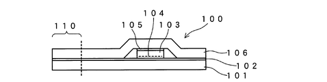
- FIG. 1 shows an identification medium 100 of the embodiment.
- the identification medium 100 has a thin plate (film shape) structure in which the front and back surfaces are covered with support films 101 and 106 which are examples of a support.
- a thermoplastic elastomer is suitable because it can be touched by hand and can be sewn.
- a polyurethane film which is one of thermoplastic elastomers is used as the support films 101 and 106.
- the support films 101 and 106 have a thickness of about 10 ⁇ m to 100 ⁇ m, preferably about 10 ⁇ m to 50 ⁇ m.
- the support films 101 and 106 are transparent (transmit visible light), have flexibility (softness), and do not disturb the state of polarization of the transmitted visible light and are water resistant.
- a polyurethane film is most suitable as such a material. Examples of materials that can be used as the support films 101 and 106 include acrylic, polycarbonate, polyester, polyimide, and the like in addition to the polyurethane film.
- Support films 101 and 106 are bonded together by an adhesive layer 102 made of a transparent adhesive.
- a cholesteric liquid crystal layer 103 is held between the support films 101 and 106.
- the cholesteric liquid crystal layer 103 is set, for example, to an optical characteristic that selectively reflects red right circularly polarized light.
- the setting of the selectively reflecting color (wavelength) and the turning direction of the selectively reflected circularly polarized light is arbitrary. For example, the setting of selectively reflecting green left circularly polarized light is possible.
- a structure in which a plurality of cholesteric liquid crystal layers that selectively reflect colors of different wavelengths are stacked, or a structure in which a circularly polarizing filter layer is combined with a cholesteric liquid crystal layer are also possible.
- the cholesteric liquid crystal layer 103 has a thickness of about 1 to 10 ⁇ m, and an embossing 104 for forming a hologram is applied to one surface thereof.
- the embossing 104 for forming a hologram is formed by pressing an emboss type against the cholesteric liquid crystal layer 103.
- the hologram image can be observed by optical interference when the reflected light of the cholesteric liquid crystal layer 103 is observed by the embossing 104 for forming the hologram.
- symbols, character information, various pattern codes, and the like can be displayed.
- the cholesteric liquid crystal layer 103 is fixed to the support film 106 via the transparent adhesive layer 105, and is fixed to the support film 101 via the transparent adhesive layer 102.
- a cholesteric liquid crystal layer 103 is formed on a substrate (not shown).
- a hologram type emboss type
- an embossing process 104 for forming a hologram is performed.
- the cholesteric liquid crystal layer 103 is peeled off from a substrate (not shown), and it is bonded to one side of the support film 106 via a transparent adhesive layer 105. In this way, an intermediate member on the support film 106 side is obtained.
- the substrate that supports the liquid crystal layer 103 is made of a material that does not disturb the state of polarized light that is transmitted, the cholesteric liquid crystal layer 103 may be adhered to the support film 106 together with the substrate.
- a support film 101 provided with a transparent adhesive layer 102 is prepared, and its adhesive surface is bonded to the above-mentioned intermediate member on the support film 106 side to obtain an identification medium 100 having a cross-sectional structure shown in FIG.
- FIG. 1 the state in which the support film 106 is deformed due to the presence of the cholesteric liquid crystal layer 103 is exaggerated, but this is a problem of drawing, and the support film 101 side is deformed.
- both of the support films 101 and 106 may be deformed.
- the identification medium 100 is fixed to the object using an attachment area (sewing area) indicated by reference numeral 110.
- the attachment region 110 is a portion where the support films 101 and 106 are bonded together by the adhesive layer 102.
- the portion of the attachment region 110 is sewn with a thread to a part of the cloth product or the leather product, or to a tag portion attached to the clothing item or the leather product.
- a polyurethane film is employed as the support films 101 and 106
- normal sewing processing is possible, and attachment to an object can be performed by sewing using a normal sewing technique.
- a method for fixing the identification medium 100 to an object a method such as hot melt can be used as a method for fixing the identification medium 100 to an object.
- a method such as hot melt can be used as a method for fixing the identification medium 100 to an object.
- the identification medium 100 is sewn on one side, but may be on both sides or the entire surface.
- the identification medium 100 has a similar identification function on both sides. For example, consider the case where observation is performed from above. Here, it is assumed that the cholesteric liquid crystal layer 103 is configured to selectively reflect red right circularly polarized light. In this case, when the identification medium 100 is directly viewed in an environment where natural light strikes, the reflected light from the cholesteric liquid crystal layer 103 can be observed, so that a red hologram image is visually recognized.
- the right circular polarization filter that selectively transmits the right circular polarized light
- the right circular polarized light selectively reflected from the cholesteric liquid crystal layer can be selectively seen, so that the red hologram image can be clearly displayed. Is observed.
- the right circular polarization selectively reflected from the cholesteric liquid crystal layer 103 is blocked by the left circular polarization filter.
- the reflected light from the layer 103 cannot be observed, and the identification medium 100 is transparent, the hologram is not visible, and the other side of the identification medium 100 is seen through from the viewpoint of the observer.
- the above optical functions are the same when the identification medium 100 is observed from the lower direction in the figure.
- the same optical function can also be obtained by irradiating with right circularly polarized light instead of observing through the right circularly polarizing filter, or by irradiating with left circularly polarized light instead of observing through the left circularly polarized filter. Can do.
- the identification medium 100 can be sewn to a clothing or leather product with a thread using the attachment region 110 where the cholesteric liquid crystal layer 103 does not exist.
- a polyurethane film is used as the support films 101 and 106, it is easy to sew, and high strength can be obtained in the sewed state.
- sewing the identification medium 100 onto the object it is difficult to remove the identification medium 100 from the object, and unauthorized reuse of the identification medium 100 can be prevented.
- the polyurethane film is flexible and water-resistant, the structure using the polyurethane film as the support films 101 and 106 has a high possibility of touching the skin and is applicable to clothing that is washed. Suitable for Further, since the cholesteric liquid crystal material is inferior in abrasion resistance, it is preferable from the viewpoint of durability to have a structure in which it is sandwiched between polyurethane films.
- the cholesteric liquid crystal layer 103 exhibits the same optical characteristics on both the front and back surfaces, when the identification medium 100 is used as a tag for clothing or leather products, identification from both sides of the tag becomes possible. Since tags attached to clothing often bend and the front and back are reversed, it is useful to have a structure that can be distinguished from the front and back.
- the cholesteric liquid crystal layer 103 has a color shift function in which the color changes when the viewing angle is changed, but even when the identification medium 100 is bent, the angle of the line of sight with respect to the cholesteric liquid crystal layer 103 changes. A color shift can be observed. Therefore, for example, when the identification medium 100 is used as a tag of clothing, a color shift of the cholesteric liquid crystal layer 103 is observed by picking and bending the tag with a finger, and this can be used for identification. This color shift is particularly noticeable in the observation of selectively reflected light using a circular polarizing filter. Therefore, in the observation through the circular polarizing filter, the identification medium 100 is bent, and the change in the hue of the hologram image at that time is changed. Identification can also be performed by observation.
- the front and back can be compared.
- one of the curved front and back surfaces is convex and the other is concave, so a color shift with gradation is observed partially, and the state is different between the front and back, and the appearance is unique. It becomes.
- the appearance of the color shift showing a partial gradation on the front and back sides is characteristic and unique, which is difficult to reproduce with a counterfeit product, and provides a high identification function.
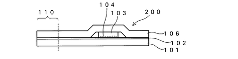
- FIG. 2 shows an identification medium 200 according to an embodiment. 2, the same reference numerals as those in FIG. 1 are the same as those described with reference to FIG. 1. This is the same in the embodiments in FIG.
- the identification medium 200 differs from the identification medium 100 shown in FIG. 1 in that the transparent adhesive layer 105 is not included in the identification medium 200.
- a transparent adhesive layer 102 is formed on a support film 101, and then a cholesteric liquid crystal layer 103 on which an embossing 104 for forming a hologram is applied is fixed thereon.
- a support film 106 is attached to the exposed surface of the transparent adhesive layer 102 to obtain an identification medium 200 having a cross-sectional structure shown in FIG.
- the identification medium 200 has a simpler structure than the identification medium 100.
- the optical function and superiority of the identification medium 200 are the same as those of the identification medium 100 of FIG.
- the embossing 104 for hologram formation may be provided on the upper surface side of the cholesteric liquid crystal layer 103 in the figure (the optical function for observing the hologram image is the same regardless of which surface is formed).
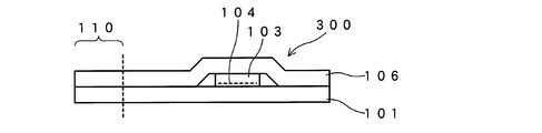
- FIG. 3 shows an identification medium 300 according to an embodiment.
- the identification medium 300 is different from the identification medium 100 of FIG. 1 in that the transparent adhesive layers 102 and 105 are not included in the identification medium 300.
- a cholesteric liquid crystal layer 103 having an embossing 104 for hologram formation is sandwiched between the support films 101 and 106, and the support films 101 and 106 made of polyurethane film are mutually bonded by self-fusion by heating. It sticks to.
- the cholesteric liquid crystal layer 103 is physically held between the support films 101 and 106.
- the identification medium 300 has a simpler structure than the identification medium 100 or 200.
- the optical function and superiority of the identification medium 300 are the same as those of the identification medium 100 of FIG.
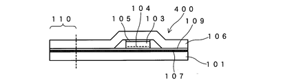
- FIG. 4 shows an identification medium 400 of the embodiment.
- the identification medium 400 is obtained by adding an ink layer 107 to the structure of the identification medium 100 of FIG.
- the ink layer 107 is provided on the support film 101 by direct printing.
- the display content of the ink layer 107 is not particularly limited, and characters, designs, patterns, codes, and the like can be displayed.
- the color of the ink layer 107 is not particularly limited, and may be a single color or a combination of a plurality of colors.
- a transparent adhesive layer 109 is provided on the ink layer 107, the cholesteric liquid crystal layer 103 is fixed on the adhesive layer 109, and the support films 101 and 106 are bonded together by the adhesive layer 109.
- FIG. 4 shows a state in which the ink layer 107 is provided on the entire surface, but it may be in a state where ink partially exists and other portions transmit visible light.
- the color and thickness of the ink layer 107 are set so that the cholesteric liquid crystal layer 103 can be seen through the ink layer 107 when the cholesteric liquid crystal layer 103 is observed through the ink layer 107. Yes. Therefore, the hologram of the cholesteric liquid crystal layer 103 can be observed through the ink layer 107 also from the back side (the lower side of the figure).
- the design and characters of the print pattern of the ink layer 107 are added as identification information.
- the printed pattern of the ink layer 107 can be visually recognized regardless of the presence or absence of the circular polarizing filter and the turning direction. That is, in the observation with the left and right circular polarizing filters switched, an observation state in which the hologram and the print pattern appear to overlap each other and an observation state in which the hologram does not appear (disappear) and the print pattern that has overlapped the hologram selectively switches. Optical function can be obtained.
- the identification medium 400 is tilted or identified while observing the portion where the hologram image of the cholesteric liquid crystal layer 103 and the print pattern of the ink layer 107 overlap.
- the medium 400 is curved, the color of the hologram image changes due to the color shift, but it is observed that the display of the print layer 107 does not change the color.
- FIG. 5 shows an identification medium 500 of the embodiment.
- the identification medium 500 has a structure in which a printing film 108 is further added to the structure of the identification medium 400 of FIG.
- the printing film 108 is made of a material that is easy to print, is transparent, and does not disturb the polarization state of transmitted light. Examples of the material constituting the printing film 108 that satisfies this condition include a TAC film, a polycarbonate film, and an acrylic film.
- the printing film 108 may be made of a material that disturbs the polarization state of transmitted light even if it is opaque or transparent. In this case, the identification function of the cholesteric liquid crystal layer 103 when viewed from the back side is lost. .
- a printing film 108 is fixed on a support film 101 through a transparent adhesive layer 102.
- an ink layer 107 provided by printing is provided on the printing film 108.
- a transparent adhesive layer 109 is provided on the ink layer 107, the cholesteric liquid crystal layer 103 is fixed by the adhesive layer 109, and the support film 106 is bonded.
- the ink layer 107 can be easily formed by adding a film made of a material with good ink loading as the printing film 108.
- FIG. 6 shows an identification medium 600 according to an embodiment.
- the identification medium 600 has a configuration in which the support film 101 and the adhesive layer 102 are deleted from the structure of the identification medium 500 of FIG. This is the case when the printing film 108 is made of a material that disturbs the polarization state of the transmitted light even if it is opaque or transparent, and it is assumed that the printed film 108 is attached to the identification medium so that the back surface does not directly touch the skin. It is also possible to delete the support film 101. However, also in this case, the identification function of the cholesteric liquid crystal layer 103 when viewed from the back surface is lost.
- the side of the support film 106 made of a polyurethane film is brought into contact with the skin. That is, in a state in which the identification medium 600 is sewn and fixed to the clothing item that is the object, the printing film 108 is positioned between the cholesteric liquid crystal layer 103 and the clothing item, in this case, the position in contact with the clothing material. To be. By doing so, the identification medium 600 is used in a state where the print film 108 does not touch the skin and the support film 106 side touches the skin, and the texture of the polyurethane film can be utilized.
- the identification medium 600 is easy to display by printing while making use of the texture of the polyurethane film, and the structure is simplified and the cost can be reduced because the use of the polyurethane film is only on one side.
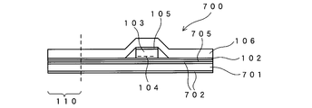
- FIG. 7 shows an identification medium 700 of the embodiment.
- the identification medium 700 uses a fabric 701 as one support and a resin support film 106 as the other support.
- a resin coating layer 702 is provided on the exposed surface side and the opposite surface of the fabric 701.
- the resin coating layer 702 is made of, for example, nylon resin.
- the resin coating layer 702 is formed, for example, by impregnating the cloth 701 with a liquid material and curing it.
- a printing layer 705 is provided in contact with the upper resin coating layer 702 in the figure.
- the print layer 705 is provided by ink printing. Characters and designs are formed by the printing layer 705.
- the upper resin coating layer 702 in the drawing functions as a base layer of the print layer 705. If the fabric 701 is used as it is, printing may be difficult depending on the type of ink or may not be suitable for printing a fine pattern. However, by providing the resin coating layer 702, a state suitable for printing can be obtained. .
- the resin coating layer 702 also functions as a permeation prevention layer for preventing liquid permeation. For example, in general, clothes are washed and dry-cleaned using a detergent and water. At this time, if the printed layer 705, the adhesive layer 102, and further the cholesteric liquid crystal layer 103 come into contact with the cleaning liquid, there arises a problem that they are altered or deteriorated. In the structure of FIG. 7, since the resin coating layer 702 functions as a permeation prevention layer that prevents the penetration of the cleaning liquid, the occurrence of these problems can be suppressed.
- the fabric 701 is a fabric formed by weaving nylon or polyester yarn.
- the fabric 701 on which the printed layer 705 is formed is bonded to the cholesteric liquid crystal layer 103 and the support film 106 by an adhesive layer 102 formed of an adhesive.
- the other parts that are the same as those of the identification medium 100 in FIG. 1 are the same as those described in relation to FIG.
- the identification medium 700 is observed from the support film 106 side.
- the right circular polarization filter when observed through the right circular polarization filter, the right circularly polarized light selectively reflected from the cholesteric liquid crystal layer 103 is preferentially seen, and the red hologram image resulting from the embossing 104 for forming the hologram is clearly seen, Furthermore, the design of the printed layer 705 can be seen at the same time.
- the right circularly polarized light reflected from the cholesteric liquid crystal layer 103 is blocked, so that the cholesteric liquid crystal layer 103 looks transparent, the hologram image becomes invisible, and the pattern of the print layer 705 is Looks preferential.
- the authenticity is determined by the switching of the images.
- the identification medium 700 is fixed to the object by sewing a portion of the attachment area (sewing area) 110 to the object with a thread. Since the cloth 701 is a cloth, even if the cloth 701 is sewn to the object with a thread, the stitched portion becomes a perforation and does not easily tear off from the portion. For this reason, the durability with respect to the force which pulls the identification medium 700 from the state sewn on the target object is high.
- a portion sewn with a thread in the portion of the attachment region (sewing region) 110 becomes a perforation, and the strength of that portion is lower than that of other portions. .
- the polyurethane film may break at the stitched portion when the force is applied to forcefully separate the identification medium 600 from the object compared to the case where the fabric 701 is used. And get higher.
- the resin coating layer 702 is easy to print, a structure in which the print layer 705 can be easily provided can be obtained.
- the presence of the resin coating layer 702 prevents the penetration of the cleaning liquid during washing with water or dry cleaning, and suppresses deterioration and deterioration of the printing layer 705, the adhesive layer 102, the cholesteric liquid crystal layer 103, and the like. It is done.
- the cloth 701 is made of a material having a light-transmitting property capable of visually recognizing the hologram due to the embossing 104
- the resin coating layer 702 and the adhesive layer 102 are made of a transparent material
- the printing layer 705 is transparent.
- a method of giving the fabric 701 light transmittance enough to make the hologram due to the embossing 104 visible a method of making the fabric rough enough to transmit visible light, and transmitting the yarn constituting the fabric light. Examples include a method of thinning to the extent that the properties are obtained, a method of forming a fabric using transparent fibers, and a method of combining a plurality of these methods.
- the support film 106 may be changed to a cloth.
- waterproofing such as providing a resin layer so that the liquid does not penetrate into the fabric.
- a fabric is used as the support of the identification medium 100
- At least one of the bodies can be a fabric.
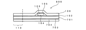
- FIG. 8 shows an identification medium 800 of the embodiment.
- a resin film 704 is disposed instead of the resin coating layer 702 as a permeation prevention layer for preventing liquid penetration in the identification medium 700.
- the resin film 704 is an example of a third support.
- the resin film 704 is the same polyurethane film as the support film 106.
- the resin film 704 is bonded to the fabric 701 with an adhesive layer 703.
- the resin film 704 By disposing the resin film 704, the penetration of the cleaning liquid into the adhesive layers 102 and 703 at the time of cleaning can be suppressed, and deterioration and deterioration of the adhesive layers 102 and 703 can be suppressed. Further, by using a polyurethane film as the resin film 704, a good texture can be obtained. In addition to the structure of FIG. 7, a structure in which a resin film 704 is disposed on the outer side (lower side) of the lower resin coating layer 703 to further enhance the liquid permeation preventing function in the structure of FIG. is there.
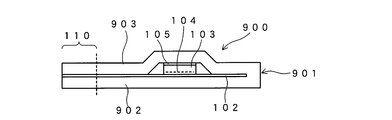
- FIG. 9 shows an identification medium 900.
- the identification medium 900 uses the one obtained by folding a single support film 901 in half in the identification medium 100 of FIG. 1 as a support. That is, the support film 901 is folded in half, and the cholesteric liquid crystal layer 103 is sandwiched and held between the folded films.
- the folded support film 901 forms one support film 902 (one support) and the other support film 902 (the other support), with the cholesteric liquid crystal layer 103 sandwiched therebetween. It becomes a retained structure.
- a polyurethane film can be used.
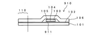
- FIG. 10 shows an identification medium 910.
- the identification medium 910 is an example in which a print layer 911 is provided in the identification medium 100 of FIG.
- the print layer 911 is provided by printing on the cholesteric liquid crystal layer 103.
- Printing on the cholesteric liquid crystal layer 103 is performed using, for example, an inkjet method.
- the printing on the polyurethane film has a problem that it is difficult to form a good printed film because the compatibility between the polyurethane and the ink may not be good.
- By directly printing on the cholesteric liquid crystal layer 103 as in the identification medium 910 it is possible to print and display the hologram display of the cholesteric liquid crystal layer in the structure shown in FIG. 1 without using a separate member as a printing base. Can be obtained.
- the present invention can be used for a technique for identifying authenticity.
Landscapes
- Physics & Mathematics (AREA)
- General Physics & Mathematics (AREA)
- Nonlinear Science (AREA)
- Chemical & Material Sciences (AREA)
- Crystallography & Structural Chemistry (AREA)
- Optics & Photonics (AREA)
- Mathematical Physics (AREA)
- Engineering & Computer Science (AREA)
- Manufacturing & Machinery (AREA)
- Polarising Elements (AREA)
- Credit Cards Or The Like (AREA)
- Holo Graphy (AREA)
Description
(構成)
図1には、実施形態の識別媒体100が示されている。識別媒体100は、表裏を支持体の一例である支持フィルム101と106によって覆われた薄板状(フィルム状)の構造を有している。支持フィルム101,106を構成する材料としては、手で触った触感や縫い付けが可能であるという点から熱可塑性エラストマーが適している。この例においては、支持フィルム101,106として、熱可塑性エラストマーの一つであるポリウレタンフィルムを用いている。支持フィルム101、106は、厚さ10μm~100μm程度、好ましくは、10μm~50μm程度の厚さのものが用いられる。支持フィルム101,106は、透明(可視光を透過)であり、可撓性(柔軟性)を有し、透過する可視光の偏光の状態を乱さず、耐水性がある材料が選択される。このような材質として、ポリウレタンフィルムが最適である。支持フィルム101,106として利用できる材料としては、ポリウレタンフィルム以外に、アクリル、ポリカーボネート、ポリエステル、ポリイミド等が挙げられる。
まず、図示しない基板上にコレステリック液晶層103を形成する。図示しない基板上でコレステリック液晶層103を形成したら、その露出面にホログラム型(エンボス型)を押し付け、ホログラム形成用のエンボス加工104を行う。次に図示しない基板上からコレステリック液晶層103を剥がし、それを支持フィルム106の片面に、透明な接着層105を介して、接着する。こうして、支持フィルム106側の中間部材を得る。なお、液晶層103を支持する基板が透過する偏光の状態を乱さない材質である場合は、コレステリック液晶層103を基板ごと支持フィルム106に接着しても良い。
識別媒体100は、符合110で示される取り付け領域(縫い付け領域)を利用して、対象物に固定される。取り付け領域110は、接着層102によって支持フィルム101と106が張り合わされている部分である。例えば、対象物が衣料品や皮革製品である場合、取り付け領域110の部分を布製品や革製品の一部、あるいは衣料品や皮革製品に取り付けられたタグの部分に糸で縫い付ける。特に支持フィルム101,106としてポリウレタンフィルムを採用した場合、通常の縫製加工が可能であり、縫い付けにより対象物への取り付けが通常の縫製技術を用いて行なえる。なお、識別媒体100を対象物に固定する方法として、ホットメルト等の方法を利用することも可能である。また、図1では識別媒体100の片側で縫い付けられているがこれ以外にも両側、もしくは全面でも良い。
識別媒体100は、表裏において同様な識別機能を有している。例えば、図の上方から観察を行なう場合を考える。なお、ここでは、コレステリック液晶層103が赤の右円偏光を選択反射する設定であるとする。この場合、自然光が当たる環境で識別媒体100を直視すると、コレステリック液晶層103からの反射光が観察できるので、赤いホログラム像が視認される。
コレステリック液晶層103が存在しない取り付け領域110を利用して、衣料品や皮革製品に識別媒体100を糸で縫い付けることができる。特に、支持フィルム101,106として、ポリウレタンフィルムを用いた場合、縫い付けが行い易く、また縫い付けた状態で高い強度を得ることができる。識別媒体100を対象物に縫い付けることで、識別媒体100を対象物から取り外すことを困難とし、識別媒体100の不正な再利用を防ぐことができる。
図2は、実施形態の識別媒体200が示されている。なお、図2において、図1と同じ符合の部分は、図1に関連して説明した部分と同じである。これは、後述する図3以下の実施形態においても同じである。
図3には、実施形態の識別媒体300が示されている。識別媒体300が図1の識別媒体100と異なるのは、透明な接着層102および105が識別媒体300にはない点である。識別媒体300の場合、支持フィルム101と106の間にホログラム形成用のエンボス加工104を施したコレステリック液晶層103を挟み、ポリウレタンフィルムにより構成された支持フィルム101と106を加熱による自己融着により相互に固着する。コレステリック液晶層103は、物理的に支持フィルム101と106との間に挟まれる形で保持される。識別媒体300は、識別媒体100や200に比較して、構造が簡素となる。識別媒体300の光学機能や優位性は、図1の識別媒体100と同じである。
図4には、実施形態の識別媒体400が示されている。識別媒体400は、図1の識別媒体100の構造に、更にインク層107を加えたものである。識別媒体400では、支持フィルム101上に直接印刷によりインク層107が設けられている。インク層107の表示の内容は特に限定されず、文字、図柄、模様、コード表示等が可能である。また、インク層107の色彩も特に限定されず、単色であってもよいし、複数の色の組み合わせであってもよい。インク層107の上に透明な接着層109が設けられ、この接着層109上にコレステリック液晶層103が固定され、また接着層109によって支持フィルム101と106が貼り合わされている。
図5には、実施形態の識別媒体500が示されている。識別媒体500は、図4の識別媒体400の構造に印刷用フィルム108を更に加えた構造を有する。印刷用フィルム108は、印刷が容易であり、透明で、且つ、透過する光の偏光状態を乱さない材質が採用される。この条件を満たす印刷用フィルム108を構成する材料としては、例えば、TACフィルム、ポリカーボネートフィルムやアクリルフィルムが挙げられる。なお、印刷フィルム108として、不透明、もしくは透明であっても透過する光の偏光状態を乱す材質を用いても良いが、この場合は裏面から見た時のコレステリック液晶層103の識別機能は失われる。
図6には、実施形態の識別媒体600が示されている。識別媒体600は、図5の識別媒体500の構造から支持フィルム101および接着層102を削除した構成を有する。印刷フィルム108を不透明、もしくは透明であっても透過する光の偏光状態を乱す材質を用いた場合で、かつ、裏面が直接肌に触れないように識別媒体に取り付けることを想定した場合、このように支持フィルム101を削除することも可能である。ただしこの場合も、裏面から見た時のコレステリック液晶層103の識別機能は失われる。
図7には、実施形態の識別媒体700が示されている。識別媒体700は、一方の支持体として、布地701を用い、他方の支持体として樹脂製の支持フィルム106を用いている。布地701の露出面側およびその反対の側の面には、樹脂のコーティング層702が設けられている。樹脂のコーティング層702は、例えばナイロン樹脂により構成されている。樹脂のコーティング層702は、例えば、液状の材料を布地701に含浸させ、硬化させることで形成される。
図8には、実施形態の識別媒体800が示されている。識別媒体800は、識別媒体700において、液体の浸透を防止する浸透防止層として、樹脂のコーティング層702の代わりに樹脂フィルム704を配置している。樹脂フィルム704は、第3の支持体の一例である。樹脂フィルム704は、支持フィルム106と同じポリウレタンフィルムである。樹脂フィルム704は、接着層703によって、布地701に接着されている。
図9には、識別媒体900が示されている。識別媒体900は、図1の識別媒体100において、1枚の支持フィルム901を2つ折りに折り曲げたものを支持体として利用している。すなわち、支持フィルム901は、2つ折りにされ、その折り曲げた間にコレステリック液晶層103が挟まれて保持されている。この場合、折り曲げられた支持フィルム901により、一方の支持フィルム902(一方の支持体)と他方の支持フィルム902(他方の支持体)が構成され、その間にコレステリック液晶層103が挟まれた状態で保持された構造となる。折り曲げることが可能な支持フィルムとしては、例えば、ポリウレタンフィルムを用いることができる。また、折り曲げることが可能な支持体として、布地を用い、この布地を折り曲げ、その間にコレステリック液晶層を保持する構造も可能である。
図10には、識別媒体910が示されている。識別媒体910は、図1の識別媒体100において、印刷層911を設けた例である。この場合、印刷層911は、コレステリック液晶層103に印刷を行うことで設けられている。コレステリック液晶層103に対する印刷は、例えば、インクジェット法を用いて行われる。
Claims (9)
- ホログラム加工が施されたコレステリック液晶と、
前記コレステリック液晶を間に挟み、少なくとも一方が前記コレステリック液晶から反射される円偏光の偏光を乱さない透明な材質により構成された第1の支持体および第2の支持体と、
対象物に縫い付けられる取り付け領域と
を備えることを特徴とする識別媒体。 - 前記第1の支持体および前記第2の支持体の少なくとも一方がポリウレタンフィルムであることを特徴とする請求項1に記載の識別媒体。
- 前記第1の支持体または前記第2の支持体の他方が布地であり、
前記布地の一部に前記取り付け領域が設けられていることを特徴とする請求項2に記載の識別媒体。 - 前記布地に樹脂のコート層が設けられていることを特徴とする請求項3に記載の識別媒体。
- 前記布地を覆って樹脂により構成された第3の支持体が設けられていることを特徴とする請求項3または4に記載の識別媒体。
- 前記コレステリック液晶に重ねて印刷表示を行うインク層が設けられ、
前記コレステリック液晶越しに前記インク層が視認可能であることを特徴とする請求項1~5のいずれか一項に記載の識別媒体。 - 前記インク層が設けられた印刷用フィルムを備えることを特徴とする請求項6に記載の識別媒体。
- 前記印刷用フィルムが前記コレステリック液晶と縫い付ける対象物の間にある状態で前記取り付け領域が前記対象物に縫い付けられることを特徴とする請求項7に記載の識別媒体。
- 前記第1の支持体および前記第2の支持体が可撓性を有し、全体を湾曲させることが可能なことを特徴とする請求項1~8のいずれか一項に記載の識別媒体。
Priority Applications (4)
| Application Number | Priority Date | Filing Date | Title |
|---|---|---|---|
| CN201380019286.1A CN104246858A (zh) | 2012-04-11 | 2013-03-14 | 识别介质 |
| JP2014510087A JP5955947B2 (ja) | 2012-04-11 | 2013-03-14 | 識別媒体 |
| EP13776181.3A EP2838076A4 (en) | 2012-04-11 | 2013-03-14 | MEANS OF DISTINCTION |
| US14/391,257 US9643444B2 (en) | 2012-04-11 | 2013-03-14 | Identification medium |
Applications Claiming Priority (2)
| Application Number | Priority Date | Filing Date | Title |
|---|---|---|---|
| JP2012-090369 | 2012-04-11 | ||
| JP2012090369 | 2012-04-11 |
Publications (1)
| Publication Number | Publication Date |
|---|---|
| WO2013153903A1 true WO2013153903A1 (ja) | 2013-10-17 |
Family
ID=49327477
Family Applications (1)
| Application Number | Title | Priority Date | Filing Date |
|---|---|---|---|
| PCT/JP2013/057170 Ceased WO2013153903A1 (ja) | 2012-04-11 | 2013-03-14 | 識別媒体 |
Country Status (5)
| Country | Link |
|---|---|
| US (1) | US9643444B2 (ja) |
| EP (1) | EP2838076A4 (ja) |
| JP (1) | JP5955947B2 (ja) |
| CN (1) | CN104246858A (ja) |
| WO (1) | WO2013153903A1 (ja) |
Cited By (1)
| Publication number | Priority date | Publication date | Assignee | Title |
|---|---|---|---|---|
| JP7394359B1 (ja) | 2022-10-14 | 2023-12-08 | KeepAlive株式会社 | 革小物、サーバー、及び、革小物の製造方法 |
Families Citing this family (2)
| Publication number | Priority date | Publication date | Assignee | Title |
|---|---|---|---|---|
| GB2575457B (en) * | 2018-07-10 | 2020-08-19 | Wearable Tech Limited | Attaching light emitting devices to items of clothing |
| US11820568B2 (en) * | 2020-12-16 | 2023-11-21 | Steris Corporation | Fluorinated shrink wrap for surgical item identification tags |
Citations (6)
| Publication number | Priority date | Publication date | Assignee | Title |
|---|---|---|---|---|
| JPH0934342A (ja) | 1995-07-17 | 1997-02-07 | Pilot Ink Co Ltd | ホログラム布帛又は合成皮革及びその製造方法 |
| WO2000013065A1 (fr) * | 1998-08-27 | 2000-03-09 | Nippon Mitsubishi Oil Corporation | Systeme de detection d'authenticite et procede d'utilisation d'un film de detection d'authenticite |
| JP2000322665A (ja) * | 1999-04-20 | 2000-11-24 | Vergara Miguel Angel Guillo | 盗難防止用の織物製ラベル |
| JP2005331917A (ja) * | 2004-04-22 | 2005-12-02 | Yukihiro Kobayashi | 薄型表示体及びその製造方法 |
| JP2006215477A (ja) * | 2005-02-07 | 2006-08-17 | Nhk Spring Co Ltd | 識別媒体および識別媒体を備えた物品 |
| JP2008015682A (ja) * | 2006-07-04 | 2008-01-24 | Dainippon Printing Co Ltd | 非接触データキャリア装置及び非接触データキャリアの取り付け方法 |
Family Cites Families (9)
| Publication number | Priority date | Publication date | Assignee | Title |
|---|---|---|---|---|
| CN2508330Y (zh) * | 2001-11-21 | 2002-08-28 | 北京酷绅服装有限公司 | 一种服饰标识牌 |
| CN2710085Y (zh) * | 2004-04-27 | 2005-07-13 | 洪骏 | 一种多用途标牌 |
| JP4549119B2 (ja) * | 2004-07-15 | 2010-09-22 | 日本発條株式会社 | 識別媒体および識別媒体を備えた物品 |
| JP4539909B2 (ja) * | 2004-10-01 | 2010-09-08 | 日本発條株式会社 | 識別媒体およびその識別方法 |
| US20080138543A1 (en) * | 2004-12-24 | 2008-06-12 | Nhk Spring Co., Ltd. | Identification Medium, Article Equipped With Identification Medium, Identifying Method And Device |
| JP4875003B2 (ja) * | 2008-01-22 | 2012-02-15 | 日本発條株式会社 | 識別媒体およびその製造方法 |
| US20100005694A1 (en) * | 2008-07-14 | 2010-01-14 | Forte Michael A | Apparel Attachable Detachable Display Frame |
| JP4897084B2 (ja) * | 2008-07-25 | 2012-03-14 | 株式会社エヌエスケーエコーマーク | マーク用生地およびそれを用いたマーク形成方法 |
| US8449166B2 (en) * | 2009-12-25 | 2013-05-28 | Dai Nippon Printing Co., Ltd. | Image source unit and display device including the same |
-
2013
- 2013-03-14 WO PCT/JP2013/057170 patent/WO2013153903A1/ja not_active Ceased
- 2013-03-14 JP JP2014510087A patent/JP5955947B2/ja active Active
- 2013-03-14 CN CN201380019286.1A patent/CN104246858A/zh active Pending
- 2013-03-14 US US14/391,257 patent/US9643444B2/en active Active
- 2013-03-14 EP EP13776181.3A patent/EP2838076A4/en not_active Withdrawn
Patent Citations (7)
| Publication number | Priority date | Publication date | Assignee | Title |
|---|---|---|---|---|
| JPH0934342A (ja) | 1995-07-17 | 1997-02-07 | Pilot Ink Co Ltd | ホログラム布帛又は合成皮革及びその製造方法 |
| WO2000013065A1 (fr) * | 1998-08-27 | 2000-03-09 | Nippon Mitsubishi Oil Corporation | Systeme de detection d'authenticite et procede d'utilisation d'un film de detection d'authenticite |
| JP4268336B2 (ja) | 1998-08-27 | 2009-05-27 | 新日本石油株式会社 | 真正性識別システム並びに真正性識別フィルムの使用方法 |
| JP2000322665A (ja) * | 1999-04-20 | 2000-11-24 | Vergara Miguel Angel Guillo | 盗難防止用の織物製ラベル |
| JP2005331917A (ja) * | 2004-04-22 | 2005-12-02 | Yukihiro Kobayashi | 薄型表示体及びその製造方法 |
| JP2006215477A (ja) * | 2005-02-07 | 2006-08-17 | Nhk Spring Co Ltd | 識別媒体および識別媒体を備えた物品 |
| JP2008015682A (ja) * | 2006-07-04 | 2008-01-24 | Dainippon Printing Co Ltd | 非接触データキャリア装置及び非接触データキャリアの取り付け方法 |
Non-Patent Citations (1)
| Title |
|---|
| See also references of EP2838076A4 * |
Cited By (2)
| Publication number | Priority date | Publication date | Assignee | Title |
|---|---|---|---|---|
| JP7394359B1 (ja) | 2022-10-14 | 2023-12-08 | KeepAlive株式会社 | 革小物、サーバー、及び、革小物の製造方法 |
| JP2024058338A (ja) * | 2022-10-14 | 2024-04-25 | KeepAlive株式会社 | 革小物、サーバー、及び、革小物の製造方法 |
Also Published As
| Publication number | Publication date |
|---|---|
| JPWO2013153903A1 (ja) | 2015-12-17 |
| EP2838076A1 (en) | 2015-02-18 |
| EP2838076A4 (en) | 2015-12-23 |
| US20150062504A1 (en) | 2015-03-05 |
| US9643444B2 (en) | 2017-05-09 |
| JP5955947B2 (ja) | 2016-07-20 |
| CN104246858A (zh) | 2014-12-24 |
Similar Documents
| Publication | Publication Date | Title |
|---|---|---|
| JP6911394B2 (ja) | 光透過型導電積層体、それを用いた光透過型導電成形体 | |
| JP5661652B2 (ja) | 識別媒体およびその識別方法 | |
| JP5955947B2 (ja) | 識別媒体 | |
| CA2943592C (en) | Security booklet | |
| CN101116125B (zh) | 识别介质以及具备识别介质的物品 | |
| KR100866572B1 (ko) | 의류용 필름접착시트 | |
| JP4429657B2 (ja) | ラベル | |
| JP4549119B2 (ja) | 識別媒体および識別媒体を備えた物品 | |
| US20120027988A1 (en) | Printed emblem for securing to a first fabric | |
| US8839727B2 (en) | Textile | |
| US8440291B2 (en) | Borderless emblem for securing to a first fabric | |
| EP3931003B1 (en) | Attachment layer for attaching a data sheet in a security document | |
| JP2011256511A (ja) | 昇華転写プリント繊維製品 | |
| JP2014108576A (ja) | 潜像印刷物 | |
| JP2005029946A (ja) | 光学機能繊維、物品、織布、不織布、光学機能繊維の製造方法および識別方法 | |
| JP3112491U (ja) | バーコードラベル | |
| JP2005331917A (ja) | 薄型表示体及びその製造方法 | |
| KR20220159648A (ko) | 벨크로가 일체화된 식별용 패치 | |
| CN206788901U (zh) | 具有隐藏标识码的衣服标签及衣服 | |
| CA2579109A1 (en) | Patterns having variable colors | |
| WO2020249601A1 (en) | A security sheet | |
| JP2010222716A (ja) | 立体マーク | |
| JP2014092686A (ja) | 識別媒体 | |
| KR20200077784A (ko) | 은화를 포함하는 보안 시트 | |
| KR19990018885U (ko) | 홀로그램은박지를이용한라벨 |
Legal Events
| Date | Code | Title | Description |
|---|---|---|---|
| 121 | Ep: the epo has been informed by wipo that ep was designated in this application |
Ref document number: 13776181 Country of ref document: EP Kind code of ref document: A1 |
|
| ENP | Entry into the national phase |
Ref document number: 2014510087 Country of ref document: JP Kind code of ref document: A |
|
| WWE | Wipo information: entry into national phase |
Ref document number: 14391257 Country of ref document: US |
|
| NENP | Non-entry into the national phase |
Ref country code: DE |
|
| WWE | Wipo information: entry into national phase |
Ref document number: 2013776181 Country of ref document: EP |