WO2013154041A1 - 電子機器 - Google Patents
電子機器 Download PDFInfo
- Publication number
- WO2013154041A1 WO2013154041A1 PCT/JP2013/060445 JP2013060445W WO2013154041A1 WO 2013154041 A1 WO2013154041 A1 WO 2013154041A1 JP 2013060445 W JP2013060445 W JP 2013060445W WO 2013154041 A1 WO2013154041 A1 WO 2013154041A1
- Authority
- WO
- WIPO (PCT)
- Prior art keywords
- panel
- electronic device
- slide cover
- edge
- housing
- Prior art date
- Legal status (The legal status is an assumption and is not a legal conclusion. Google has not performed a legal analysis and makes no representation as to the accuracy of the status listed.)
- Ceased
Links
Images

Classifications
-
- G—PHYSICS
- G11—INFORMATION STORAGE
- G11B—INFORMATION STORAGE BASED ON RELATIVE MOVEMENT BETWEEN RECORD CARRIER AND TRANSDUCER
- G11B17/00—Guiding record carriers not specifically of filamentary or web form, or of supports therefor
- G11B17/02—Details
- G11B17/04—Feeding or guiding single record carrier to or from transducer unit
- G11B17/0401—Details
- G11B17/0405—Closing mechanism, e.g. door
-
- G—PHYSICS
- G11—INFORMATION STORAGE
- G11B—INFORMATION STORAGE BASED ON RELATIVE MOVEMENT BETWEEN RECORD CARRIER AND TRANSDUCER
- G11B33/00—Constructional parts, details or accessories not provided for in the other groups of this subclass
- G11B33/02—Cabinets; Cases; Stands; Disposition of apparatus therein or thereon
- G11B33/022—Cases
-
- G—PHYSICS
- G11—INFORMATION STORAGE
- G11B—INFORMATION STORAGE BASED ON RELATIVE MOVEMENT BETWEEN RECORD CARRIER AND TRANSDUCER
- G11B33/00—Constructional parts, details or accessories not provided for in the other groups of this subclass
- G11B33/02—Cabinets; Cases; Stands; Disposition of apparatus therein or thereon
- G11B33/027—Covers
-
- G—PHYSICS
- G11—INFORMATION STORAGE
- G11B—INFORMATION STORAGE BASED ON RELATIVE MOVEMENT BETWEEN RECORD CARRIER AND TRANSDUCER
- G11B33/00—Constructional parts, details or accessories not provided for in the other groups of this subclass
- G11B33/14—Reducing influence of physical parameters, e.g. temperature change, moisture, dust
- G11B33/1406—Reducing the influence of the temperature
- G11B33/1413—Reducing the influence of the temperature by fluid cooling
- G11B33/142—Reducing the influence of the temperature by fluid cooling by air cooling
Definitions
- the present invention relates to an electronic device that can use an optical disk.
- An electronic device having a slot needs a loading mechanism for transporting an optical disk inserted into the slot into the electronic device.
- Such a mechanism includes relatively expensive parts, which increases the cost of the electronic device.
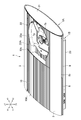
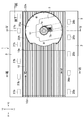
- the electronic device 1 has a slide cover 10, a front panel 2, a rear panel 3, and a second side portion 22 ⁇ / b> B included in the housing 20, which will be described later, on the upper surface thereof.
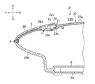
- the upper surface of the electronic device 1 is curved so that the position of the central portion in the front-rear direction of the upper surface is higher than the front edge 1b and the rear edge 1c.
- the upper surface of the electronic device 1 is curved from the front edge 1b to the rear edge 1c. That is, the upper surface of the electronic device 1 is curved in the entire region from the front edge 1b to the rear edge 1c.
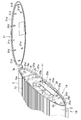
- the electronic apparatus 1 of this example has a substantially elliptical columnar upper portion 1A having an axis C1 (see FIG. 1) along the left-right direction.
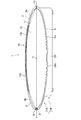
- the side surface of the upper part 1 ⁇ / b> A of the electronic device 1 is elliptical and has a long axis A.
- the plane including the major axis A and the axis C1 is horizontal. That is, the plane including the long axis A and the axis C1 is parallel to the bottom surface of the electronic device 1 (specifically, the bottom surface of the lower part 1B described later).
- the upper surface of the electronic device 1 constitutes a portion above the plane including the major axis A and the axis C1 in the outer peripheral surface of the elliptic cylinder.
- the slide cover 10 is slidable in the left-right direction between a closed position (FIG. 1) that covers the media storage portion 22a and an open position (FIG. 2) that exposes the media storage portion 22a.
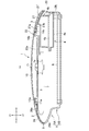
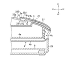
- the slide cover 10 is curved in accordance with the upper surface of the electronic device 1 described above. That is, the slide cover 10 is curved so that the position of the center portion in the front-rear direction is higher than the front edge and the rear edge. According to such a slide cover 10, it becomes easier to secure a distance between the bottom portion of the disk accommodating portion 22 a and the slide cover 10 than when the slide cover 10 is formed in a flat plate shape. As a result, the height h (see FIG. 5) of the rotation drive unit 7a can be increased, and the user can easily perform operations such as fitting the optical disk D into the rotation drive unit 7a and removing the optical disk D from the rotation drive unit 7a. Can be
- the rotation driving unit 7 a is located below the top P ⁇ b> 1 that is the highest position in the slide cover 10.
- the top portion P ⁇ b> 1 of the slide cover 10 coincides with the top portion of the upper surface of the electronic device 1.
- the rotation drive part 7a is located below the top part P1. That is, the center line C2 of the rotation drive unit 7a passes through the top P1. Therefore, the height of the rotation drive part 7a can be increased further easily.
- the freedom degree of the structure of the chucking mechanism provided in the rotation drive part 7a can be increased.
- the second side portion 22B is curved according to the slide cover 10, the front edge of the second side portion 22B (that is, the front edge 22c of the upper panel portion 22) and the rear edge of the second side portion 22B (that is, Due to the fact that the rear edge 22d) of the upper panel portion 22 is located below the edges of the panels 2 and 3, respectively, it is possible to suppress the concavity between them being noticeable. As a result, the design uniformity of the upper surface of the electronic device 1 can be achieved.
- the housing 20 has a side inner panel portion 25.
- the side inner panel portion 25 is formed in the upper housing 21.
- the side inner panel portion 25 constitutes the upper portion 1A of the electronic device 1 and has a substantially elliptical shape in a side view.
- the side panel 31 is attached to the side inner panel portion 25, and the side portion of the electronic device 1 has a double structure including the side inner panel portion 25 and the side panel 31. Thereby, the strength of the housing 20 can be increased.
- an opening for inserting the hard disk device 13 is formed in the side inner panel portion 25 shown in FIG. 8 provided on the right side of the upper housing 21, and the side panel 31 attaches the hard disk device 13 to the side panel 31. It also functions as a panel to hide.
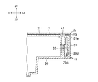
- the upper housing 21 and the lower housing 29 are fixed to each other by screws 41 as shown in FIG.
- the upper surface of the electronic device 1 may be curved so as to constitute a part of the outer circumferential surface of the cylinder, instead of being curved so as to constitute the outer circumferential surface of the elliptic cylinder.
- both or one of the front panel 2 and the rear panel 3 may not necessarily be provided.
- the front portion (that is, the front inner panel portion 26) or the rear portion (that is, the rear inner panel portion 27) of the upper housing 21 may constitute the upper surface of the electronic device 1.
Landscapes
- Casings For Electric Apparatus (AREA)
- Slot Machines And Peripheral Devices (AREA)
- Feeding And Guiding Record Carriers (AREA)
Description
Claims (10)
- 前縁及び後縁よりも前後方向の中央部の位置が高くなるように前記前縁から前記後縁に亘って湾曲している上面と、
前記上面の一部を構成するカバーであって、当該カバーの前縁及び後縁よりも前後方向の中央部の位置が高くなるように前記上面に合わせて湾曲し、開位置と閉位置との間でスライド可能なスライドカバーと、
前記閉位置にあるスライドカバーによって覆われる、光ディスクを配置するためのディスク収容部と、
前記ディスク収容部に設けられ、前記光ディスクの中心穴に嵌められ前記光ディスクを回転させる回転駆動部と、
を備えることを特徴とする電子機器。 - 請求項1に記載の電子機器において、
前記スライドカバーは、当該スライドカバーの一方側に設けられる第1のパネルと、当該スライドカバーの他方側に設けられる第2のパネルとの間でスライド可能となっており、
前記電子機器の上面には、前記第1のパネルに沿って形成され、前記スライドカバーをガイドする第1のガイド部と、前記第2のパネルに沿って形成され、前記スライドカバーをガイドする第2のガイド部と、が設けられている、
ことを特徴とする電子機器。 - 請求項1に記載の電子機器において、
前記電子機器の上面の前部を構成するフロントパネルと、前記電子機器の上面の後部を構成するリアパネルとを備え、
前記スライドカバーは前記フロントパネルと前記リアパネルとの間で左右方向にスライド可能となっている、
ことを特徴とする電子機器。 - 請求項3に記載の電子機器において、
前記フロントパネルと前記スライドカバーは面一となるように配置され、
前記フロントパネルは、当該フロントパネルの前記後縁に、斜め後方且つ下方に向いた斜面を有している、
ことを特徴とする電子機器。 - 請求項3又は4に記載の電子機器において、
前記リアパネルと前記スライドカバーは面一となるように配置され、
前記リアパネルは、当該リアパネルの前記前縁に、斜め前方且つ下方に向いた斜面を有している、
ことを特徴とする電子機器。 - 請求項1に記載の電子機器において、
前記スライドカバーの前方に位置し、前記スライドカバーとともに前記電子機器の湾曲した上面を構成するフロントパネルと、
前記フロントパネルが取り付けられる上面を有するフロントインナーパネル部を有するハウジングと、を備え、
前記フロントインナーパネル部は前記フロントパネルに合わせて湾曲している、
ことを特徴とする電子機器。 - 請求項6に記載の電子機器において、
前記ハウジングは、前記スライドカバーが上側に配置されるアッパーパネル部を備え、
前記フロントインナーパネル部は前記アッパーパネル部から前方に延びており、
前記アッパーパネル部の前縁と前記フロントパネルの後縁との間には隙間が形成され、
前記フロントインナーパネル部は前記フロントパネルとの間に隙間を有する部分を含み、
前記フロントインナーパネル部の前記部分には前記ハウジングの内側に繋がる通気穴が形成されている、
ことを特徴とする電子機器。 - 請求項1に記載の電子機器において、
前記スライドカバーの後方に位置し、前記スライドカバーとともに前記電子機器の湾曲した上面を構成するリアパネルと、
前記リアパネルが取り付けられる上面を有するリアインナーパネル部を有するハウジングと、をさらに備え、
前記リアインナーパネル部は前記リアパネルに合わせて湾曲している、
ことを特徴とする電子機器。 - 請求項8に記載の電子機器において、
前記ハウジングは、前記スライドカバーが上側に配置されるアッパーパネル部をさらに備え、
前記リアインナーパネル部は前記アッパーパネル部から後方に延びており、
前記アッパーパネル部の後縁と前記リアパネルの前縁との間には隙間が形成され、
前記リアインナーパネル部は前記リアパネルとの間に隙間を有する部分を含み、
前記リアインナーパネル部の前記部分には前記ハウジングの内側に繋がる通気穴が形成されている、
ことを特徴とする電子機器。 - 請求項3に記載の電子機器において、
前記スライドカバーは左右方向にスライド可能であり、
前記電子機器は、前記フロントパネルと前記リアパネルとの間に位置するアッパーパネル部をさらに備え、
前記アッパーパネル部は、前記スライドカバーが開位置にあるときに当該スライドカバーによって覆われ、前記スライドカバーに合わせて湾曲した板状のサイド部を有し、
前記サイド部の上面には左右方向に延びる複数の溝が形成されている、
ことを特徴とする電子機器。
Priority Applications (6)
| Application Number | Priority Date | Filing Date | Title |
|---|---|---|---|
| IN2293KON2014 IN2014KN02293A (ja) | 2012-04-13 | 2013-04-05 | |
| RU2014145521/28A RU2593683C2 (ru) | 2012-04-13 | 2013-04-05 | Электронное устройство |
| US14/391,699 US9105296B2 (en) | 2012-04-13 | 2013-04-05 | Electronic apparatus |
| EP13775852.0A EP2838088B1 (en) | 2012-04-13 | 2013-04-05 | Electronic device |
| JP2014510146A JP5818976B2 (ja) | 2012-04-13 | 2013-04-05 | 電子機器 |
| CN201380017420.4A CN104205223B (zh) | 2012-04-13 | 2013-04-05 | 电子设备 |
Applications Claiming Priority (2)
| Application Number | Priority Date | Filing Date | Title |
|---|---|---|---|
| JP2012092502 | 2012-04-13 | ||
| JP2012-092502 | 2012-04-13 |
Publications (2)
| Publication Number | Publication Date |
|---|---|
| WO2013154041A1 true WO2013154041A1 (ja) | 2013-10-17 |
| WO2013154041A9 WO2013154041A9 (ja) | 2014-08-07 |
Family
ID=49327609
Family Applications (1)
| Application Number | Title | Priority Date | Filing Date |
|---|---|---|---|
| PCT/JP2013/060445 Ceased WO2013154041A1 (ja) | 2012-04-13 | 2013-04-05 | 電子機器 |
Country Status (7)
| Country | Link |
|---|---|
| US (1) | US9105296B2 (ja) |
| EP (1) | EP2838088B1 (ja) |
| JP (1) | JP5818976B2 (ja) |
| CN (1) | CN104205223B (ja) |
| IN (1) | IN2014KN02293A (ja) |
| RU (1) | RU2593683C2 (ja) |
| WO (1) | WO2013154041A1 (ja) |
Cited By (3)
| Publication number | Priority date | Publication date | Assignee | Title |
|---|---|---|---|---|
| WO2021230246A1 (ja) | 2020-05-15 | 2021-11-18 | 株式会社ソニー・インタラクティブエンタテインメント | 電子機器のスタンド、及び電子機器組立体 |
| JPWO2024176920A1 (ja) * | 2023-02-21 | 2024-08-29 | ||
| WO2024214633A1 (ja) | 2023-04-11 | 2024-10-17 | 株式会社ソニー・インタラクティブエンタテインメント | スタンド装置 |
Families Citing this family (2)
| Publication number | Priority date | Publication date | Assignee | Title |
|---|---|---|---|---|
| JP1586534S (ja) * | 2016-09-23 | 2017-09-25 | ||
| CN113542476B (zh) * | 2020-04-16 | 2023-09-08 | 深圳富泰宏精密工业有限公司 | 背盖顶出机构及电子装置 |
Citations (4)
| Publication number | Priority date | Publication date | Assignee | Title |
|---|---|---|---|---|
| JPH087428A (ja) * | 1994-06-27 | 1996-01-12 | Matsushita Electric Ind Co Ltd | ディスク再生装置 |
| JP2000123561A (ja) * | 1998-10-09 | 2000-04-28 | Sony Corp | 記録及び/又は再生装置 |
| JP2005078733A (ja) * | 2003-09-01 | 2005-03-24 | Sony Corp | 電子機器 |
| US7687711B2 (en) | 2005-05-15 | 2010-03-30 | Sony Computer Entertainment Inc. | Electronic device |
Family Cites Families (10)
| Publication number | Priority date | Publication date | Assignee | Title |
|---|---|---|---|---|
| DE20006442U1 (de) * | 2000-04-07 | 2000-08-24 | Enlight Corp., Takang Kwei-Shan, Taoyuan | Drucktaste auf der Frontplatte eines Computers |
| US20040047617A1 (en) * | 2002-08-21 | 2004-03-11 | Matos Jose R. | Disc player system |
| TW568323U (en) * | 2002-09-27 | 2003-12-21 | Lite On It Corp | Cap opening and closing device for cap-lifting CD-ROM drive |
| JP4306228B2 (ja) * | 2002-11-13 | 2009-07-29 | ソニー株式会社 | 記録媒体カートリッジ |
| JP2006134404A (ja) * | 2004-11-04 | 2006-05-25 | Sanyo Electric Co Ltd | プレーヤの扉開閉装置 |
| US7398535B2 (en) * | 2004-12-10 | 2008-07-08 | Coby Electronics Corporation | Portable media player |
| JP2007095174A (ja) | 2005-09-29 | 2007-04-12 | Hitachi Ltd | 情報再生装置 |
| CN101587738A (zh) * | 2008-05-23 | 2009-11-25 | 鸿富锦精密工业(深圳)有限公司 | 光盘播放器 |
| CN201491429U (zh) * | 2009-09-10 | 2010-05-26 | 珠海市雅力实业有限公司 | 一种便携式多媒体设备的滑盖机构 |
| CN201820451U (zh) * | 2009-09-10 | 2011-05-04 | 珠海市雅力实业有限公司 | 一种便携式滑盖可视光盘播放机 |
-
2013
- 2013-04-05 CN CN201380017420.4A patent/CN104205223B/zh active Active
- 2013-04-05 IN IN2293KON2014 patent/IN2014KN02293A/en unknown
- 2013-04-05 RU RU2014145521/28A patent/RU2593683C2/ru active
- 2013-04-05 US US14/391,699 patent/US9105296B2/en active Active
- 2013-04-05 WO PCT/JP2013/060445 patent/WO2013154041A1/ja not_active Ceased
- 2013-04-05 EP EP13775852.0A patent/EP2838088B1/en active Active
- 2013-04-05 JP JP2014510146A patent/JP5818976B2/ja active Active
Patent Citations (4)
| Publication number | Priority date | Publication date | Assignee | Title |
|---|---|---|---|---|
| JPH087428A (ja) * | 1994-06-27 | 1996-01-12 | Matsushita Electric Ind Co Ltd | ディスク再生装置 |
| JP2000123561A (ja) * | 1998-10-09 | 2000-04-28 | Sony Corp | 記録及び/又は再生装置 |
| JP2005078733A (ja) * | 2003-09-01 | 2005-03-24 | Sony Corp | 電子機器 |
| US7687711B2 (en) | 2005-05-15 | 2010-03-30 | Sony Computer Entertainment Inc. | Electronic device |
Cited By (7)
| Publication number | Priority date | Publication date | Assignee | Title |
|---|---|---|---|---|
| WO2021230246A1 (ja) | 2020-05-15 | 2021-11-18 | 株式会社ソニー・インタラクティブエンタテインメント | 電子機器のスタンド、及び電子機器組立体 |
| US12234942B2 (en) | 2020-05-15 | 2025-02-25 | Sony Interactive Entertainment Inc. | Stand for electronic device and electronic device assembly |
| EP4697138A2 (en) | 2020-05-15 | 2026-02-18 | Sony Interactive Entertainment Inc. | Stand for electronic device and electronic device assembly |
| JPWO2024176920A1 (ja) * | 2023-02-21 | 2024-08-29 | ||
| WO2024176920A1 (ja) * | 2023-02-21 | 2024-08-29 | 株式会社ソニー・インタラクティブエンタテインメント | 電子機器組立体、電子機器、及びスタンド |
| WO2024214633A1 (ja) | 2023-04-11 | 2024-10-17 | 株式会社ソニー・インタラクティブエンタテインメント | スタンド装置 |
| EP4697129A1 (en) | 2023-04-11 | 2026-02-18 | Sony Interactive Entertainment Inc. | Stand device |
Also Published As
| Publication number | Publication date |
|---|---|
| EP2838088B1 (en) | 2018-12-12 |
| IN2014KN02293A (ja) | 2015-05-01 |
| CN104205223B (zh) | 2017-05-31 |
| WO2013154041A9 (ja) | 2014-08-07 |
| JP5818976B2 (ja) | 2015-11-18 |
| RU2014145521A (ru) | 2016-06-10 |
| EP2838088A4 (en) | 2015-12-16 |
| EP2838088A1 (en) | 2015-02-18 |
| US9105296B2 (en) | 2015-08-11 |
| CN104205223A (zh) | 2014-12-10 |
| US20150082327A1 (en) | 2015-03-19 |
| RU2593683C2 (ru) | 2016-08-10 |
| JPWO2013154041A1 (ja) | 2015-12-17 |
Similar Documents
| Publication | Publication Date | Title |
|---|---|---|
| JP5818976B2 (ja) | 電子機器 | |
| JP6017954B2 (ja) | 電子機器 | |
| JP4952434B2 (ja) | 電子部品取付用部品および電子機器 | |
| US20110019353A1 (en) | Electronic apparatus | |
| JP6538607B2 (ja) | 電子機器 | |
| US8059393B2 (en) | Electronic apparatus | |
| JP6543413B2 (ja) | 電子機器 | |
| JP2009043100A (ja) | 媒体ドライブユニットおよび電子機器 | |
| JP6616493B2 (ja) | 電子機器 | |
| JP5882818B2 (ja) | 電子機器 | |
| JP6428359B2 (ja) | 記憶装置の収納ユニット及び収納ユニットを備えるストレージ装置 | |
| JP4322233B2 (ja) | 遊技機 | |
| JP4514062B2 (ja) | シャシーフロントに光ディスクドライバを装着したコンピュータのケース | |
| TW201510992A (zh) | 硬碟機托架 | |
| JP4829189B2 (ja) | 電子機器および表示パネル用筐体 | |
| JP6293091B2 (ja) | ディスク装置 | |
| JP5065443B2 (ja) | 遊技機 | |
| JP2019153346A (ja) | 電子機器 | |
| JP2012048747A (ja) | 電子機器 | |
| JP2010252179A (ja) | スライド部材組立体,スライド部材組立体の使用方法,及びスライド部材組立体を備えた筐体装置 | |
| JP2009238350A (ja) | カバー及び収容カバー | |
| JP2012160209A (ja) | 媒体ドライブユニットおよび電子機器 |
Legal Events
| Date | Code | Title | Description |
|---|---|---|---|
| 121 | Ep: the epo has been informed by wipo that ep was designated in this application |
Ref document number: 13775852 Country of ref document: EP Kind code of ref document: A1 |
|
| WWE | Wipo information: entry into national phase |
Ref document number: 2013775852 Country of ref document: EP |
|
| ENP | Entry into the national phase |
Ref document number: 2014510146 Country of ref document: JP Kind code of ref document: A |
|
| WWE | Wipo information: entry into national phase |
Ref document number: 14391699 Country of ref document: US |
|
| NENP | Non-entry into the national phase |
Ref country code: DE |
|
| ENP | Entry into the national phase |
Ref document number: 2014145521 Country of ref document: RU Kind code of ref document: A |
|
| REG | Reference to national code |
Ref country code: BR Ref legal event code: B01A Ref document number: 112014024452 Country of ref document: BR |
|
| ENP | Entry into the national phase |
Ref document number: 112014024452 Country of ref document: BR Kind code of ref document: A2 Effective date: 20140930 |