WO2013157317A1 - 空気電池用正極及びその製造方法 - Google Patents
空気電池用正極及びその製造方法 Download PDFInfo
- Publication number
- WO2013157317A1 WO2013157317A1 PCT/JP2013/056419 JP2013056419W WO2013157317A1 WO 2013157317 A1 WO2013157317 A1 WO 2013157317A1 JP 2013056419 W JP2013056419 W JP 2013056419W WO 2013157317 A1 WO2013157317 A1 WO 2013157317A1
- Authority
- WO
- WIPO (PCT)
- Prior art keywords
- layer
- liquid
- positive electrode
- tight
- catalyst layer
- Prior art date
- Legal status (The legal status is an assumption and is not a legal conclusion. Google has not performed a legal analysis and makes no representation as to the accuracy of the status listed.)
- Ceased
Links
Images


Classifications
-
- H—ELECTRICITY
- H01—ELECTRIC ELEMENTS
- H01M—PROCESSES OR MEANS, e.g. BATTERIES, FOR THE DIRECT CONVERSION OF CHEMICAL ENERGY INTO ELECTRICAL ENERGY
- H01M4/00—Electrodes
- H01M4/86—Inert electrodes with catalytic activity, e.g. for fuel cells
- H01M4/8605—Porous electrodes
- H01M4/8626—Porous electrodes characterised by the form
-
- H—ELECTRICITY
- H01—ELECTRIC ELEMENTS
- H01M—PROCESSES OR MEANS, e.g. BATTERIES, FOR THE DIRECT CONVERSION OF CHEMICAL ENERGY INTO ELECTRICAL ENERGY
- H01M4/00—Electrodes
- H01M4/86—Inert electrodes with catalytic activity, e.g. for fuel cells
- H01M4/8605—Porous electrodes
-
- B—PERFORMING OPERATIONS; TRANSPORTING
- B29—WORKING OF PLASTICS; WORKING OF SUBSTANCES IN A PLASTIC STATE IN GENERAL
- B29C—SHAPING OR JOINING OF PLASTICS; SHAPING OF MATERIAL IN A PLASTIC STATE, NOT OTHERWISE PROVIDED FOR; AFTER-TREATMENT OF THE SHAPED PRODUCTS, e.g. REPAIRING
- B29C41/00—Shaping by coating a mould, core or other substrate, i.e. by depositing material and stripping-off the shaped article; Apparatus therefor
- B29C41/003—Shaping by coating a mould, core or other substrate, i.e. by depositing material and stripping-off the shaped article; Apparatus therefor characterised by the choice of material
-
- B—PERFORMING OPERATIONS; TRANSPORTING
- B29—WORKING OF PLASTICS; WORKING OF SUBSTANCES IN A PLASTIC STATE IN GENERAL
- B29C—SHAPING OR JOINING OF PLASTICS; SHAPING OF MATERIAL IN A PLASTIC STATE, NOT OTHERWISE PROVIDED FOR; AFTER-TREATMENT OF THE SHAPED PRODUCTS, e.g. REPAIRING
- B29C41/00—Shaping by coating a mould, core or other substrate, i.e. by depositing material and stripping-off the shaped article; Apparatus therefor
- B29C41/02—Shaping by coating a mould, core or other substrate, i.e. by depositing material and stripping-off the shaped article; Apparatus therefor for making articles of definite length, i.e. discrete articles
- B29C41/22—Making multilayered or multicoloured articles
-
- B—PERFORMING OPERATIONS; TRANSPORTING
- B29—WORKING OF PLASTICS; WORKING OF SUBSTANCES IN A PLASTIC STATE IN GENERAL
- B29C—SHAPING OR JOINING OF PLASTICS; SHAPING OF MATERIAL IN A PLASTIC STATE, NOT OTHERWISE PROVIDED FOR; AFTER-TREATMENT OF THE SHAPED PRODUCTS, e.g. REPAIRING
- B29C41/00—Shaping by coating a mould, core or other substrate, i.e. by depositing material and stripping-off the shaped article; Apparatus therefor
- B29C41/34—Component parts, details or accessories; Auxiliary operations
- B29C41/36—Feeding the material on to the mould, core or other substrate
-
- B—PERFORMING OPERATIONS; TRANSPORTING
- B29—WORKING OF PLASTICS; WORKING OF SUBSTANCES IN A PLASTIC STATE IN GENERAL
- B29C—SHAPING OR JOINING OF PLASTICS; SHAPING OF MATERIAL IN A PLASTIC STATE, NOT OTHERWISE PROVIDED FOR; AFTER-TREATMENT OF THE SHAPED PRODUCTS, e.g. REPAIRING
- B29C41/00—Shaping by coating a mould, core or other substrate, i.e. by depositing material and stripping-off the shaped article; Apparatus therefor
- B29C41/34—Component parts, details or accessories; Auxiliary operations
- B29C41/42—Removing articles from moulds, cores or other substrates
-
- B—PERFORMING OPERATIONS; TRANSPORTING
- B29—WORKING OF PLASTICS; WORKING OF SUBSTANCES IN A PLASTIC STATE IN GENERAL
- B29C—SHAPING OR JOINING OF PLASTICS; SHAPING OF MATERIAL IN A PLASTIC STATE, NOT OTHERWISE PROVIDED FOR; AFTER-TREATMENT OF THE SHAPED PRODUCTS, e.g. REPAIRING
- B29C41/00—Shaping by coating a mould, core or other substrate, i.e. by depositing material and stripping-off the shaped article; Apparatus therefor
- B29C41/34—Component parts, details or accessories; Auxiliary operations
- B29C41/46—Heating or cooling
-
- H—ELECTRICITY
- H01—ELECTRIC ELEMENTS
- H01M—PROCESSES OR MEANS, e.g. BATTERIES, FOR THE DIRECT CONVERSION OF CHEMICAL ENERGY INTO ELECTRICAL ENERGY
- H01M12/00—Hybrid cells; Manufacture thereof
- H01M12/04—Hybrid cells; Manufacture thereof composed of a half-cell of the fuel-cell type and of a half-cell of the primary-cell type
- H01M12/06—Hybrid cells; Manufacture thereof composed of a half-cell of the fuel-cell type and of a half-cell of the primary-cell type with one metallic and one gaseous electrode
-
- H—ELECTRICITY
- H01—ELECTRIC ELEMENTS
- H01M—PROCESSES OR MEANS, e.g. BATTERIES, FOR THE DIRECT CONVERSION OF CHEMICAL ENERGY INTO ELECTRICAL ENERGY
- H01M12/00—Hybrid cells; Manufacture thereof
- H01M12/08—Hybrid cells; Manufacture thereof composed of a half-cell of a fuel-cell type and a half-cell of the secondary-cell type
-
- H—ELECTRICITY
- H01—ELECTRIC ELEMENTS
- H01M—PROCESSES OR MEANS, e.g. BATTERIES, FOR THE DIRECT CONVERSION OF CHEMICAL ENERGY INTO ELECTRICAL ENERGY
- H01M4/00—Electrodes
- H01M4/86—Inert electrodes with catalytic activity, e.g. for fuel cells
- H01M4/8636—Inert electrodes with catalytic activity, e.g. for fuel cells with a gradient in another property than porosity
- H01M4/8642—Gradient in composition
-
- H—ELECTRICITY
- H01—ELECTRIC ELEMENTS
- H01M—PROCESSES OR MEANS, e.g. BATTERIES, FOR THE DIRECT CONVERSION OF CHEMICAL ENERGY INTO ELECTRICAL ENERGY
- H01M4/00—Electrodes
- H01M4/86—Inert electrodes with catalytic activity, e.g. for fuel cells
- H01M4/8647—Inert electrodes with catalytic activity, e.g. for fuel cells consisting of more than one material, e.g. consisting of composites
- H01M4/8657—Inert electrodes with catalytic activity, e.g. for fuel cells consisting of more than one material, e.g. consisting of composites layered
-
- H—ELECTRICITY
- H01—ELECTRIC ELEMENTS
- H01M—PROCESSES OR MEANS, e.g. BATTERIES, FOR THE DIRECT CONVERSION OF CHEMICAL ENERGY INTO ELECTRICAL ENERGY
- H01M4/00—Electrodes
- H01M4/86—Inert electrodes with catalytic activity, e.g. for fuel cells
- H01M4/8663—Selection of inactive substances as ingredients for catalytic active masses, e.g. binders, fillers
- H01M4/8673—Electrically conductive fillers
-
- H—ELECTRICITY
- H01—ELECTRIC ELEMENTS
- H01M—PROCESSES OR MEANS, e.g. BATTERIES, FOR THE DIRECT CONVERSION OF CHEMICAL ENERGY INTO ELECTRICAL ENERGY
- H01M4/00—Electrodes
- H01M4/86—Inert electrodes with catalytic activity, e.g. for fuel cells
- H01M4/88—Processes of manufacture
- H01M4/8803—Supports for the deposition of the catalytic active composition
- H01M4/8807—Gas diffusion layers
-
- H—ELECTRICITY
- H01—ELECTRIC ELEMENTS
- H01M—PROCESSES OR MEANS, e.g. BATTERIES, FOR THE DIRECT CONVERSION OF CHEMICAL ENERGY INTO ELECTRICAL ENERGY
- H01M4/00—Electrodes
- H01M4/86—Inert electrodes with catalytic activity, e.g. for fuel cells
- H01M4/88—Processes of manufacture
- H01M4/8803—Supports for the deposition of the catalytic active composition
- H01M4/8814—Temporary supports, e.g. decal
-
- H—ELECTRICITY
- H01—ELECTRIC ELEMENTS
- H01M—PROCESSES OR MEANS, e.g. BATTERIES, FOR THE DIRECT CONVERSION OF CHEMICAL ENERGY INTO ELECTRICAL ENERGY
- H01M4/00—Electrodes
- H01M4/86—Inert electrodes with catalytic activity, e.g. for fuel cells
- H01M4/88—Processes of manufacture
- H01M4/8825—Methods for deposition of the catalytic active composition
- H01M4/8828—Coating with slurry or ink
-
- H—ELECTRICITY
- H01—ELECTRIC ELEMENTS
- H01M—PROCESSES OR MEANS, e.g. BATTERIES, FOR THE DIRECT CONVERSION OF CHEMICAL ENERGY INTO ELECTRICAL ENERGY
- H01M4/00—Electrodes
- H01M4/86—Inert electrodes with catalytic activity, e.g. for fuel cells
- H01M4/88—Processes of manufacture
- H01M4/8878—Treatment steps after deposition of the catalytic active composition or after shaping of the electrode being free-standing body
- H01M4/8882—Heat treatment, e.g. drying, baking
-
- B—PERFORMING OPERATIONS; TRANSPORTING
- B29—WORKING OF PLASTICS; WORKING OF SUBSTANCES IN A PLASTIC STATE IN GENERAL
- B29K—INDEXING SCHEME ASSOCIATED WITH SUBCLASSES B29B, B29C OR B29D, RELATING TO MOULDING MATERIALS OR TO MATERIALS FOR MOULDS, REINFORCEMENTS, FILLERS OR PREFORMED PARTS, e.g. INSERTS
- B29K2027/00—Use of polyvinylhalogenides or derivatives thereof as moulding material
- B29K2027/12—Use of polyvinylhalogenides or derivatives thereof as moulding material containing fluorine
- B29K2027/18—PTFE, i.e. polytetrafluoroethylene, e.g. ePTFE, i.e. expanded polytetrafluoroethylene
-
- B—PERFORMING OPERATIONS; TRANSPORTING
- B29—WORKING OF PLASTICS; WORKING OF SUBSTANCES IN A PLASTIC STATE IN GENERAL
- B29K—INDEXING SCHEME ASSOCIATED WITH SUBCLASSES B29B, B29C OR B29D, RELATING TO MOULDING MATERIALS OR TO MATERIALS FOR MOULDS, REINFORCEMENTS, FILLERS OR PREFORMED PARTS, e.g. INSERTS
- B29K2105/00—Condition, form or state of moulded material or of the material to be shaped
- B29K2105/0005—Condition, form or state of moulded material or of the material to be shaped containing compounding ingredients
- B29K2105/002—Agents changing electric characteristics
- B29K2105/0023—Agents changing electric characteristics improving electric conduction
-
- B—PERFORMING OPERATIONS; TRANSPORTING
- B29—WORKING OF PLASTICS; WORKING OF SUBSTANCES IN A PLASTIC STATE IN GENERAL
- B29K—INDEXING SCHEME ASSOCIATED WITH SUBCLASSES B29B, B29C OR B29D, RELATING TO MOULDING MATERIALS OR TO MATERIALS FOR MOULDS, REINFORCEMENTS, FILLERS OR PREFORMED PARTS, e.g. INSERTS
- B29K2105/00—Condition, form or state of moulded material or of the material to be shaped
- B29K2105/04—Condition, form or state of moulded material or of the material to be shaped cellular or porous
-
- B—PERFORMING OPERATIONS; TRANSPORTING
- B29—WORKING OF PLASTICS; WORKING OF SUBSTANCES IN A PLASTIC STATE IN GENERAL
- B29K—INDEXING SCHEME ASSOCIATED WITH SUBCLASSES B29B, B29C OR B29D, RELATING TO MOULDING MATERIALS OR TO MATERIALS FOR MOULDS, REINFORCEMENTS, FILLERS OR PREFORMED PARTS, e.g. INSERTS
- B29K2995/00—Properties of moulding materials, reinforcements, fillers, preformed parts or moulds
- B29K2995/0037—Other properties
- B29K2995/0065—Permeability to gases
-
- B—PERFORMING OPERATIONS; TRANSPORTING
- B29—WORKING OF PLASTICS; WORKING OF SUBSTANCES IN A PLASTIC STATE IN GENERAL
- B29L—INDEXING SCHEME ASSOCIATED WITH SUBCLASS B29C, RELATING TO PARTICULAR ARTICLES
- B29L2031/00—Other particular articles
- B29L2031/34—Electrical apparatus, e.g. sparking plugs or parts thereof
- B29L2031/3468—Batteries, accumulators or fuel cells
-
- H—ELECTRICITY
- H01—ELECTRIC ELEMENTS
- H01M—PROCESSES OR MEANS, e.g. BATTERIES, FOR THE DIRECT CONVERSION OF CHEMICAL ENERGY INTO ELECTRICAL ENERGY
- H01M4/00—Electrodes
- H01M4/86—Inert electrodes with catalytic activity, e.g. for fuel cells
- H01M2004/8678—Inert electrodes with catalytic activity, e.g. for fuel cells characterised by the polarity
- H01M2004/8689—Positive electrodes
-
- H—ELECTRICITY
- H01—ELECTRIC ELEMENTS
- H01M—PROCESSES OR MEANS, e.g. BATTERIES, FOR THE DIRECT CONVERSION OF CHEMICAL ENERGY INTO ELECTRICAL ENERGY
- H01M4/00—Electrodes
- H01M4/86—Inert electrodes with catalytic activity, e.g. for fuel cells
- H01M4/8663—Selection of inactive substances as ingredients for catalytic active masses, e.g. binders, fillers
- H01M4/8668—Binders
-
- Y—GENERAL TAGGING OF NEW TECHNOLOGICAL DEVELOPMENTS; GENERAL TAGGING OF CROSS-SECTIONAL TECHNOLOGIES SPANNING OVER SEVERAL SECTIONS OF THE IPC; TECHNICAL SUBJECTS COVERED BY FORMER USPC CROSS-REFERENCE ART COLLECTIONS [XRACs] AND DIGESTS
- Y02—TECHNOLOGIES OR APPLICATIONS FOR MITIGATION OR ADAPTATION AGAINST CLIMATE CHANGE
- Y02E—REDUCTION OF GREENHOUSE GAS [GHG] EMISSIONS, RELATED TO ENERGY GENERATION, TRANSMISSION OR DISTRIBUTION
- Y02E60/00—Enabling technologies; Technologies with a potential or indirect contribution to GHG emissions mitigation
- Y02E60/10—Energy storage using batteries
Definitions
- the present invention relates to a positive electrode used in an air battery.
- the present invention relates to a positive electrode for an air battery, which suppresses leakage of an electrolytic solution and is excellent in series connection and handling of the air battery, and a method of manufacturing the same.
- a button type air battery is known as a conventional air battery.
- the button type air battery uses a case fitting body in which a metal negative electrode case and a metal positive electrode case having air holes are fitted together via a gasket.
- a negative electrode, an electrolytic solution, a separator, an air electrode (positive electrode), a water repellent film, and the like are disposed inside the case fitting body.
- the internal space of the case fitting is divided by the separator. Then, one space is filled with zinc and an electrolytic solution impregnated therein to form a negative electrode, and the other space is provided with a catalyst to form an air electrode (positive electrode). Further, on the surface of the air electrode opposite to the separator, a water repellent film made of a porous film made of polytetrafluoroethylene (PTFE) is disposed. The diffusion paper is disposed in close contact with the water repellent film.
- PTFE polytetrafluoroethylene
- oxygen in air as a positive electrode active material is taken in from an air hole provided at the bottom of the positive electrode case, and is supplied to the air electrode through diffusion paper and a water repellent film.
- the diffusion paper functions to uniformly supply oxygen to the entire surface of the cathode.
- the water repellent film functions to supply oxygen to the inside of the battery (positive electrode) and prevent the electrolyte from leaking out of the battery through the air holes.
- the air cell comprises a frusto-conical shaped air electrode with a reduced diameter in the direction from the gas diffusion layer to the top surface of the catalyst layer.
- This button-type air battery is excellent in the liquid leakage resistance because it is possible to suppress the massive catalyst generated due to the collapse of the catalyst layer from being trapped as the foreign matter between the component parts.
- the conventional button type air battery can prevent the electrolyte from leaking due to the massive catalyst, the electrolyte leakage from the air hole is still made of PTFE film provided separately from the air electrode (positive electrode) I could only prevent it with a water repellent film.
- the conductivity decreases when such a water repellent film is disposed, it has been necessary to dispose a current collector in the catalyst layer.
- An object of the present invention is to provide a positive electrode for an air battery, which is useful for series connection of air batteries by suppressing leakage of an electrolytic solution, and capable of enhancing the production efficiency and the handleability, and a method for producing the same.
- the positive electrode for an air battery is a liquid-tight air-permeable membrane comprising a catalyst layer comprising a porous layer comprising conductive carbon, a binder and a catalyst component, and a porous layer comprising conductive carbon and a binder. And a layer, wherein a liquid-tight gas-permeable layer is laminated on the catalyst layer.
- FIG. 1 is a partial cross-sectional view schematically showing a fine structure of a positive electrode for an air battery according to an embodiment of the present invention.
- FIG. 2 is a schematic cross-sectional view showing an example of a series-type air battery using the positive electrode for air battery according to the embodiment of the present invention.
- FIG. 3 is a scanning electron micrograph showing the cross section of the positive electrode sheet of Example 2.
- FIG. 1 schematically shows the fine structure of the air battery positive electrode according to the present embodiment.
- the positive electrode layer 10 which is the positive electrode for air battery of the present embodiment includes a catalyst layer 11 and a liquid-tight gas-permeable layer 12, and the liquid-tight gas-permeable layer 12 is laminated on the catalyst layer 11 .
- the liquid-tight gas-permeable layer 12 is “stacked” on the catalyst layer 11.
- the liquid-tight ventilation layer 12 is disposed on the side on which both layers are adjacent and on the side on which the air intake hole or the air channel to the catalyst layer 11 is disposed, that is, the side on which the electrolyte is disposed. Just do it. Therefore, it is not necessarily limited to the word "stacking".
- the catalyst layer 11 contains carbon particles 1 as aggregate carbon, carbon black 1 b which is an example of a conductive pass material, catalyst particles 3 as a catalyst component, and a binder 2. Then, the carbon particles 1, the carbon black 1b and the catalyst particles 3 are bound by the binder 2 to form a porous layer.
- the liquid-tight ventilation layer 12 contains a graphite 1a which is an example of aggregate carbon, a carbon black 1b which is an example of a conductive path material, and a binder 2. Then, the graphite 1 a and the carbon black 1 b are bound by the binder 2 to form a porous layer.
- the catalyst layer 11 and the liquid-tight gas-permeable layer 12 are bound by the binder 2 to be substantially integrated. Such integration can be performed by integral molding in the manufacturing method of the air battery positive electrode described later.
- carbon particles 1, graphite (aggregate carbon) 1a and carbon black (conductive path material) 1b are all made of conductive carbon.
- fibrous carbon made of conductive carbon can also be added to at least one of the catalyst layer 11 and the liquid-tight gas-permeable layer 12.
- the addition of fibrous carbon can improve the mechanical strength, in particular the tensile strength, of the resulting positive electrode.
- the addition of such fibrous carbon is preferably carried out particularly for the liquid tight aeration layer. That is, since the thickness of the liquid-tight air-permeable layer can be reduced by the improvement of the mechanical strength, it is possible to increase the output of the positive electrode obtained while reducing the electric resistance.
- both the catalyst layer 11 and the liquid tight aeration layer 12 are porous layers.
- the liquid-tight air-permeable layer 12 has a pore diameter and a porosity that allow oxygen in the air to permeate but not allow the electrolyte (not shown) to permeate.
- the pore size of the liquid-tight aeration layer 12 is preferably about 0.1 ⁇ m to 20 ⁇ m, and the porosity is preferably about 10 to 80%.
- the pore size and the porosity can be measured by a pore distribution measuring device such as a porosimeter.
- the liquid-tight air-permeable layer 12 has high liquid repellency (water repellency) to the electrolyte of the air battery, and liquid repellency higher than that of the catalyst layer 11, ie, liquid repellency equal to or larger than that of the catalyst layer 11. Have sex. Thereby, the electrolyte can be sufficiently suppressed from leaking out of the air battery through an air intake hole (air hole) or an air intake flow passage (air flow passage) or the like (not shown). Further, unlike the conventional PTFE water repellent film, the liquid-tight gas-permeable layer 12 has conductivity due to the graphite 1a which is aggregate carbon contained therein and the carbon black 1b which is a conductive pass material. Therefore, as described below, it is extremely advantageous to construct a series type air battery having a large electromotive force.
- FIG. 2 an example of the assembled battery using the series type air battery provided with the positive electrode for air batteries of this embodiment is shown.
- the positive electrode layer 10 and the negative electrode layer 20 formed by laminating the liquid-tight ventilation layer 12 on the catalyst layer 11 are the separators 30 impregnated with the electrolyte. Adjacent through. Further, the liquid-tight air-permeable layer 12 of the positive electrode layer 10 is exposed to the air flow path 40, and oxygen in air is supplied to the catalyst layer 11.
- a holder 60 is disposed on the outer periphery of the positive electrode layer 10 and the negative electrode layer 20, and the outer periphery of the positive electrode layer 10 and the negative electrode layer 20 and the holder 60 are integrally joined.
- the electrolyte solution is prevented from leaking from the junction between the positive electrode layer 10 and the negative electrode layer 20 and the holder 60.
- a current collector 50 having a corrugated cross section is provided in the air flow path 40 between the air battery A and the air battery B. In this manner, the air batteries A and B have a stacked structure in which the air batteries A and B are stacked via the current collector 50, thereby forming a battery assembly.
- the positive electrode for an air battery of the present embodiment is suitable for forming a series assembled battery having a structure as shown in FIG. According to the series type assembled battery having such a structure, a large electromotive force can be easily realized, the size can be reduced, and the work efficiency of the assembly can be improved.
- the electrolytic solution (not shown) is impregnated in the separator 30.
- the electrolytic solution may be in contact with the positive electrode and the negative electrode, the space between the positive electrode and the negative electrode may be filled with the electrolytic solution without using the separator 30. Further, it may be contained in the positive electrode or the negative electrode, and may be held by being impregnated in the catalyst layer 11 and the negative electrode layer 20.
- the liquid-tight gas-permeable layer 12 is also a porous layer, so the contact state at the interface between the catalyst layer 11 and the liquid-tight gas-permeable layer 12 is good. Therefore, a three-layer interface of the catalyst particle 3, oxygen, and the electrolytic solution is easily formed, and efficient power generation can be performed.
- the catalyst particles 3 as the catalyst component are sufficient as long as they are contained in the catalyst layer 11, but they may be contained in the liquid tight aeration layer 12.
- the catalyst particles 3 as the catalyst component have a catalyst layer rather than the liquid tight aeration layer 12. It is preferable to contain many in 11.
- the catalyst layer 11 preferably contains 50% by mass or more of the total catalyst amount in the air battery positive electrode, and more preferably 70% by mass or more of the total catalyst amount.
- the catalyst particles 3 be contained at a position 10 ⁇ m or more from the outermost surface 12 a of the liquid-tight aeration layer 12.
- the effects of the present invention can be exhibited even if the position is shallower than this range, that is, within the range of less than 10 nm from the outermost surface 12 a of the liquid-tight ventilation layer 12.
- catalyst particles are included in this range, a trace amount of electrolyte may leak into the air flow path via the catalyst particles.
- the liquid-tight ventilation layer 12 is superior to the catalyst layer 11, but in the present embodiment, the softening temperature of the liquid-tight ventilation layer is higher than the softening temperature of the catalyst layer. High is preferred.
- the reason for this also relates to a method of manufacturing a positive electrode for an air battery, etc. In the step of applying an ink for catalyst layer or attaching a separately prepared catalyst layer to a liquid-tight gas-permeable layer having high strength, Softening the layer makes it possible to bond the catalyst layer more easily.
- the softening temperature of the liquid-tight air-permeable layer and the catalyst layer is measured by measuring each layer according to Japanese Industrial Standard JIS K7191-2 (Plastics-Determination of deflection temperature under load-Part 2: Plastics and evonite). It can be asked.
- the relationship between the above-mentioned catalyst layer and the softening temperature in the liquid-tight aeration layer can be adjusted mainly by the type and the amount of the binder used in both layers.
- the binder amount of the liquid-tight air-permeable layer may be larger than the binder amount of the catalyst layer.
- the content ratio in the case of using the same or the same material as the binder can be appropriately changed depending on the type of binder used, etc.
- the binder content may be 7/10 to 1/10.
- the softening temperature of the binder in the liquid-tight ventilation layer is the softening of the binder in the catalyst layer. It is preferred that the temperature be higher.
- the difference in the softening temperature of the binder used in both layers can be appropriately changed depending on the purpose of use of the air battery, the type of the electrolytic solution, the type of the conductive carbon, and the like.
- the difference between the softening temperature of the binder of the liquid-tight air-permeable layer and the softening temperature of the binder of the catalyst layer is preferably about 30 to 250.degree.
- the Vicat softening temperature of the binder can be determined in accordance with JIS K 7206 (plastic-thermoplastic-Vicat softening temperature (VST) test method). In addition, even in the case of using different types of binders in both layers, the respective contents can be appropriately adjusted.
- JIS K 7206 plastic-thermoplastic-Vicat softening temperature (VST) test method.
- the catalyst layer 11 and the liquid-tight air-permeable layer 12 can be integrally formed by a manufacturing method described later, whereby both layers can be integrated. Such integral molding can significantly improve the manufacturing efficiency of the positive electrode. Furthermore, by improving the interface characteristics between the catalyst layer and the liquid-tight aeration layer, the advantage of being able to reduce the IR resistance of the positive electrode can be obtained.
- Conductive carbon It will not specifically limit, if it is a carbon material which has electroconductivity as electroconductive carbon which comprises a catalyst layer and a liquid-tight air-permeable layer.
- the conductive carbon at least one selected from the group consisting of activated carbon other than diamond, graphite, flaky graphite, carbon black and acetylene black can be used.
- such conductive carbon is, from its function, to aggregate carbon which forms the main skeleton of the layer structure (porous layer structure) and a conductive path material useful for forming a conductive passage in the layer. It is divided roughly.
- the fibrous carbon described above can also be added as conductive carbon to at least one of the catalyst layer and the liquid-tight gas-permeable layer.
- Fibrous carbon contributes to the improvement of the mechanical strength of the catalyst layer and the liquid-tight gas-permeable layer, the reduction of the layer thickness, and the reduction of the electrical resistance.
- a fibrous carbon at least one selected from the group consisting of curviline nanotubes (CNT), carbon nanofibers (CNF) and vapor grown carbon fibers (VGCF) is used. be able to.
- aggregate carbon it is preferable to use at least one selected from the group consisting of activated carbon, graphite and scaly graphite. All of these have the property of retaining independent particle shapes to some extent in the porous layer. In particular, when graphite or scale-like graphite is used, a relatively large number of gaps are easily formed in the porous layer, and therefore, it is suitable for use as aggregate carbon of the liquid-tight ventilation layer.
- the conductive path materials are easily connected to each other to easily form a chain (string) structure, and the formed connecting chains tend to function as conductive paths.
- the connecting chains of the conductive path material are easily arranged so as to sew the gaps formed in the porous layer, the conductivity of the porous layer as a whole is improved. It is extremely useful.
- a conductive pass material at least one of carbon black and acetylene black can be used.
- acetylene black obtained by thermal decomposition of acetylene gas is easy to adopt the above-mentioned chain-like structure, and the surface exhibits water repellency, and therefore, is suitable as a conductive pass material of the liquid-tight ventilation layer.
- the particle size of the aggregate carbon and the conductive path material described above is influenced by the air battery used and the target electromotive force, but typically, the average particle size of the aggregate carbon is 5 ⁇ m to 300 ⁇ m,
- the average particle size of the conductive pass material is preferably 50 nm to 500 nm.
- the average particle diameter of aggregate carbon is within the above range, it is possible to enhance the conductivity in the surface direction of aggregate carbon and the strength of the positive electrode.
- the average particle diameter of the conductive pass material is in the above range, it is possible to enhance the conductivity in the thickness direction of the porous layer and the gas permeability of the liquid-tight gas-permeable layer.
- the average particle diameter (median diameter, D50) of the aggregate carbon and the conductive path material can be determined by a dynamic light scattering method.
- binder As a binder, it is sufficient if it has a function capable of forming a porous layer by binding conductive carbon such as the above-mentioned aggregate carbon or conductive path material, but it is lyophobic to an electrolytic solution, typically It is preferable to have water repellency.
- polyethylene polyethylene
- PP polypropylene
- PET polyethylene terephthalate
- PEN polyether nitrile
- PAN polyacrylonitrile
- PA polyamide
- CMC carboxymethyl cellulose
- PVC polyvinyl chloride
- SBR styrene butadiene rubber
- isoprene rubber butadiene rubber
- ethylene propylene rubber ethylene propylene diene copolymer
- styrene / isoprene / styrene block copolymers and their thermoplastic polymers such as hydrogenated products
- PVDF polyvinylidene fluoride
- PTFE polytetrafluoroethylene
- polyvinylidene fluoride polyimide, styrene butadiene rubber, carboxymethyl cellulose, polypropylene, polytetrafluoroethylene, polyacrylonitrile and polyamide can be mentioned.
- binders may be used alone or in combination of two or more.
- binders from the viewpoint of heat resistance and chemical resistance, polytetrafluoroethylene (PTFE), polypropylene (PP), tetrafluoroethylene / perfluoroalkylvinylether copolymer (PFA), tetrafluoroethylene Hexafluoropropylene copolymer (FEP) and ethylene tetrafluoroethylene copolymer (ETFE) can be particularly preferably used.
- PTFE polytetrafluoroethylene
- PP polypropylene
- PFA tetrafluoroethylene / perfluoroalkylvinylether copolymer
- FEP tetrafluoroethylene Hexafluoropropylene copolymer
- ETFE ethylene tetrafluoroethylene copolymer
- Catalytic component As a catalyst component, a conventionally known electrode catalyst for air battery positive electrode can be used. Specifically, platinum (Pt), ruthenium (Ru), iridium (Ir), rhodium (Rh), palladium (Pd), osmium (Os), tungsten (W), lead (Pb), iron (Fe), Metals such as chromium (Cr), cobalt (Co), nickel (Ni), manganese (Mn), vanadium (V), molybdenum (Mo), gallium (Ga), aluminum (Al) and compounds thereof, and alloys thereof Etc. can be illustrated. Such catalyst components may be used alone or in combination of two or more.
- the shape and size of the catalyst component are not particularly limited, and the same shape and size as those of conventionally known catalyst components can be employed, but it is preferably granular.
- the average particle diameter of catalyst particles as a catalyst component is preferably 30 nm to 10 ⁇ m. When the average particle size of the catalyst particles is in such a range, it is possible to appropriately control the balance between the catalyst utilization rate and the convenience of catalyst loading related to the effective electrode surface on which the electrochemical reaction proceeds.
- the average particle size of the catalyst particles can be measured as a crystallite size determined from the half width of the diffraction peak of the catalyst component in X-ray diffraction.
- the content ratio of the conductive carbon, the binder and the catalyst component in the catalyst layer can be appropriately changed in accordance with the electromotive force of the intended air battery, the application and the like. For example, it is preferable to adjust the conductive carbon to 30 to 85% by mass, the binder to 5 to 30% by mass, and the catalyst component to 3 to 50% by mass. When the conductive carbon, the binder and the catalyst component are in the above ranges, a sufficient output can be obtained for the obtained air battery.
- the content ratio of the conductive carbon and the binder in the liquid-tight air-permeable layer can also be appropriately changed according to the electromotive force of the intended air battery, the application and the like.
- the conductive carbon is preferably 40 to 80% by mass
- the binder is preferably 20 to 60% by mass.
- the liquid-tight gas-permeable layer may also contain a catalyst component, which is as described above.
- the mixing ratio of aggregate carbon and conductive path material is preferably 1: 4 to 3: 2 (aggregate carbon: conductive path material) by mass ratio. Within this range, sufficient output can be obtained for the obtained air battery.
- the mixing ratio of aggregate carbon and conductive path material is preferably 1: 4 to 4: 1 (aggregate carbon: conductive path material) in mass ratio. Within this range, sufficient strength and output can be obtained for the obtained air battery.
- the negative electrode layer contains, for example, a negative electrode active material consisting of a single metal or alloy having a standard electrode potential lower than that of hydrogen. In some cases, it can be formed of a porous material.
- a metal simple substance having a standard electrode potential lower than hydrogen for example, lithium (Li), zinc (Zn), iron (Fe), aluminum (Al), magnesium (Mg), manganese (Mn), silicon (Si), titanium (Ti), chromium (Cr), vanadium (V) etc. can be mentioned.
- alloys using these metal elements can also be applied.
- Such negative electrode active materials may be used alone or in combination of two or more.
- an alloy is generally a metal element to which one or more metal elements or nonmetal elements are added, and is a generic term for those having metallic properties. Specifically, those obtained by adding one or more metal elements or nonmetal elements to the above-described metal elements can be mentioned.
- component elements are separate crystals, that is, a eutectic alloy which is a so-called mixture; component elements are completely dissolved and solid solution is formed; component elements are intermetallic compounds or metals and nonmetals There are those which form a compound of Any alloy structure may be used in this embodiment.
- the present invention is not limited thereto, and conventionally known materials applied to air batteries can be used.
- separator Also as the separator, conventionally known materials used for air batteries can be used. Specifically, for an electrolytic solution which is an aqueous solution, for example, a glass paper which has not been subjected to water repelling treatment, and a microporous film made of polyolefin such as polyethylene and polypropylene can be suitably used.
- Electrolyte solution A conventionally well-known thing can also be used for electrolyte solution.
- an aqueous solution or non-aqueous solution such as potassium chloride, sodium chloride and potassium hydroxide can be used.
- the current collector is not particularly limited as long as it functions to collect current.
- a current collector made of a metal such as stainless steel (SUS), copper, or nickel can be used.
- a material obtained by coating a resin with a conductive material can be used.
- the shape is not particularly limited, and various shapes such as a wire mesh shape, an expanded metal shape, and a corrugated shape can be applied.
- the manufacturing method of the present embodiment includes the following steps (A) to (E).
- an ink for liquid-tight gas-permeable layer and an ink for catalyst layer are prepared.
- the liquid tight breathable layer ink can be obtained by mixing conductive carbon and a binder in a solvent.
- the ink for catalyst layer can be obtained by mixing conductive carbon, a binder and a catalyst component in a solvent.
- the mixing amount of each component is preferably adjusted as described above.
- the solvent used to prepare each ink is not particularly limited, and examples thereof include water and alcohol solvents such as methanol, ethanol, 1-propanol, 2-propanol, ethylene glycol and propylene glycol.
- each ink may be mixed with a known surfactant or thickener as necessary.
- the ink for liquid-tight air-permeable layer is applied onto the holder and dried. Thereby, a liquid-tight gas-permeable layer precursor is formed.
- the holding body used in the step (B) is sufficient as long as it has heat resistance to withstand drying and baking, but it is preferable that the holding body is excellent in the releasability of the liquid-tight air-permeable layer and the catalyst layer. Specifically, various glass plates, various ceramic plates, various heat resistant resin plates, etc. can be mentioned.
- the drying temperature of the liquid-tight air-permeable layer ink is not particularly limited as long as the solvent in the ink is removed, but it is preferably, for example, 80 to 120 ° C.
- step (C) the catalyst layer ink is applied onto the liquid-tight gas-permeable layer precursor solidified and dried. Thereby, a catalyst layer precursor is formed on the liquid-tight gas-permeable layer precursor.
- the drying temperature of the catalyst layer ink is not particularly limited as long as the solvent in the ink is removed, but it is preferably, for example, 80 to 120 ° C.
- step (D) the stacked liquid-tight gas-permeable layer precursor and catalyst layer precursor are calcined.
- the firing temperature is not particularly limited, but preferably 100 to 350 ° C., for example.
- the said drying and baking may be performed by inert atmosphere and may be performed in air.
- the liquid tight aeration layer and the catalyst layer obtained are peeled off from the support. Thereby, the air battery positive electrode according to the present embodiment can be obtained.
- the manufacturing method of the positive electrode for air batteries of this embodiment can also be manufactured also in the following process (A), (B '), (C'), (E).
- A A step of preparing a liquid-tight air-permeable layer ink for forming a liquid-tight air-permeable layer, and a catalyst layer ink for forming a catalyst layer.
- B ' A step of forming a liquid-tight air-permeable layer by applying and drying the liquid-tight air-permeable layer ink on a holding body and baking it.
- C ′ A step of forming a catalyst layer by applying and drying an ink for a catalyst layer on the liquid-tight aeration layer, and then baking it.
- E A step of peeling the liquid tight aeration layer and the catalyst layer from the support.
- steps (B ') and (C') after the liquid tight aeration layer is formed by applying, drying and calcining a liquid tight aeration layer ink, for the catalyst layer on the liquid tight aeration layer
- the catalyst layer may be formed by applying an ink and drying and calcining.
- the drying temperature and the baking temperature can be the same as those described above.
- the positive electrode of the present embodiment can be easily formed by using a conventional method for preparing a fuel cell electrode.
- the positive electrode may be formed by separately forming the liquid-tight air-permeable layer and the catalyst layer and then bonding them.
- this manufacturing method since a three-layer interface of oxygen, a catalyst component and an electrolyte solution is easily formed between the liquid-tight air-permeable layer and the catalyst layer, the battery output can be increased.
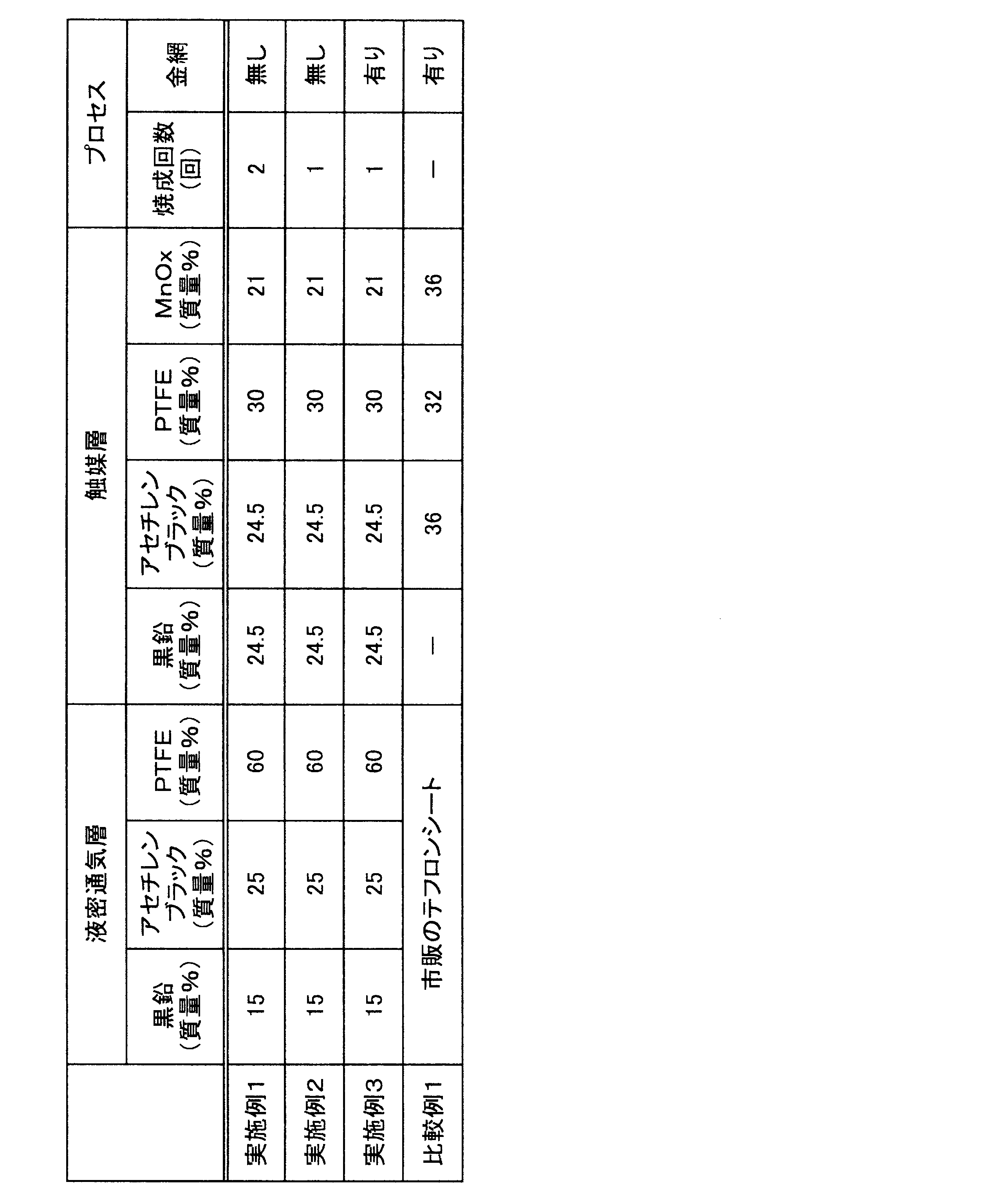
- Example 1 First, the constituent materials of the liquid-tight aeration layer and the catalyst layer shown in Table 1 below were dispersed in pure water together with a surfactant and a thickener. Thus, a liquid-tight gas-permeable layer ink and a catalyst layer ink were prepared.
- the obtained liquid-tight air-permeable layer ink was applied onto a glass plate as a holding sheet using an applicator, dried at 80 ° C. in an oven for 1 hour, and further baked at 330 ° C. for 1 hour.
- the above ink for a catalyst layer was applied onto the liquid-tight air-permeable layer calcined as described above, dried at 80 ° C. in an oven, and further calcined at 330 ° C. for 1 hour. Thereafter, the liquid-tight aeration layer and the catalyst layer after firing were peeled off from the glass plate to obtain a positive electrode sheet of this example.
- the constituent materials of each layer, the mixing amount thereof, the number of times of firing, and the presence or absence of a wire mesh as a current collector are shown in Table 1.
- Example 2 First, the constituent materials of the liquid-tight aeration layer and the catalyst layer shown in Table 1 below were dispersed in pure water together with a surfactant and a thickener. Thus, a liquid-tight gas-permeable layer ink and a catalyst layer ink were prepared.
- the obtained liquid-tight air-permeable layer ink was applied onto a glass plate as a holding sheet using an applicator and dried in an oven at 80 ° C. for 1 hour. Furthermore, the above ink for a catalyst layer was applied on the dried liquid-tight aeration layer, and dried at 80 ° C. in an oven. And after baking the laminated liquid-tight air-permeable layer precursor and catalyst layer precursor at 330 ° C. for 1 hour, the positive electrode sheet of this example was obtained by peeling it from the glass plate. The image which observed the cross section of the positive electrode sheet of this example with the scanning electron microscope is shown in FIG.
- Example 3 First, the same operation as in Example 2 was repeated to obtain a positive electrode sheet. Next, a polyvinylidene fluoride solution was applied to the metal mesh and attached to the liquid-tight air-permeable layer side of the positive electrode sheet, and then dried. Thereby, the positive electrode sheet of this example was obtained. As the metal mesh, SUS304 was plated with gold, and 200 mesh number was used.
- Comparative Example 1 Using a wire mesh (200 mesh) as a collector, a catalyst layer was formed by press-molding a mixed powder composed of constituent materials shown in Table 1 below and the collector. Next, the obtained catalyst layer and a commercially available PTFE sheet for air battery were hot-pressed at 330 ° C. to obtain a positive electrode sheet of this example.
- Examples 4 to 8 The same operation as in Example 1 was repeated except that the constituent material of the liquid-tight air-permeable layer and the mixing amount thereof were changed, to obtain positive electrode sheets of Examples 4 to 8.
- the constituent materials of the liquid-tight air-permeable layer in the positive electrode sheet of each example and the mixing amount thereof are shown in Table 3.
- constituent materials and mixing amounts of the liquid-tight ventilation layers of Examples 1 to 3 and Comparative Example 1 are also shown in Table 3.
- the thickness of the positive electrode sheet of each Example and a comparative example is written together in Table 3.
- CNF indicates carbon nanofibers, and those having a diameter of 40 to 90 nm and an aspect ratio of 1000 or more were used.
- VGCF refers to vapor grown carbon fiber, and has a diameter of 150 nm and a fiber length of 10 to 20 ⁇ m.
- ⁇ Penetration resistance> The positive electrode sheets obtained in Examples 1 to 8 and Comparative Example 1 were cut into a size of 20 mm ⁇ , and the contact resistance was measured. A contact resistance measuring device was used as the device. Then, the positive electrode sheet was sandwiched between two electrodes, and a penetration resistance (m ⁇ ⁇ cm 2 ) was measured when a current of 1 A / cm 2 was applied at a measurement surface pressure of 2.0 MPa. The penetration resistance indicates the electrical resistance value in the direction perpendicular to the sheet surface. And, the smaller the value, the more the discharge loss can be reduced. The obtained results are shown in Table 3.
- Example 5 achieves equivalent tensile strength with a thickness about half that of Example 4, since the resistance value is reduced by thinning, it is possible to obtain a higher output positive electrode. .
- a catalyst layer and a liquid-tight air-permeable layer are formed using conductive carbon and a binder, and these are stacked to form a positive electrode. Therefore, the leakage of the electrolytic solution from the positive electrode can be suppressed. Furthermore, the series connection of the air battery can be facilitated, and the manufacturing efficiency and the handleability can be enhanced.
Landscapes
- Chemical & Material Sciences (AREA)
- Chemical Kinetics & Catalysis (AREA)
- Electrochemistry (AREA)
- General Chemical & Material Sciences (AREA)
- Engineering & Computer Science (AREA)
- Manufacturing & Machinery (AREA)
- Mechanical Engineering (AREA)
- Composite Materials (AREA)
- Physics & Mathematics (AREA)
- Thermal Sciences (AREA)
- Inert Electrodes (AREA)
- Hybrid Cells (AREA)
Abstract
本発明の空気電池用正極(10)は、導電性炭素(1)とバインダー(2)と触媒成分(3)とを含有する多孔質層からなる触媒層(11)と、導電性炭素(1a)とバインダー(2)とを含有する多孔質層からなる液密通気層(12)とを備える。そして、液密通気層が触媒層に積層される。このような構成により、正極からの電解液の漏出を抑制しつつも、空気電池の直列接続を容易にすることができる。その結果、空気電池の製造効率や取り扱い性を高めることができる。
Description
本発明は、空気電池に用いられる正極に関する。詳細には、本発明は、電解液の漏出を抑制し、空気電池の直列接続性や取り扱い性に優れる空気電池用正極及びその製造方法に関する。
空気電池は、空気中の酸素を活物質として利用するものであるため経済的であり、さらに長期無保守で使用できる電源である。従来の空気電池としては、ボタン型空気電池が知られている。ボタン型空気電池は、金属製負極ケースと空気孔を有する金属製正極ケースとをガスケットを介して嵌め合せたケース嵌合体を使用する。そして、このケース嵌合体の内部に、負極、電解液、セパレータ、空気極(正極)及び撥水膜などが配置された構造を有する。
このようなボタン型空気電池においては、ケース嵌合体の内部空間がセパレータにより分割されている。そして、一方の空間は亜鉛及びこれに含浸された電解液が充填されて負極となり、他方の空間は触媒が配置されて空気極(正極)となる。また、空気極におけるセパレータと反対側の面には、ポリテトラフルオロエチレン(PTFE)製の多孔質フィルムからなる撥水膜が配置されている。そして、この撥水膜に拡散紙が密着して配置されている。
そして、ボタン型空気電池では、正極活物質としての空気中の酸素が、正極ケースの底部に設けられた空気孔から取り入れられ、拡散紙及び撥水膜を介して空気極に供給される。この場合、拡散紙は、空気極全面に酸素を均一に供給する機能を果たす。そして、撥水膜は、酸素を電池内部(正極)に供給するとともに、空気孔を介して電解液が電池外に漏出するのを防止する機能を果たす。
上述のような構成の空気電池において、ガス拡散層上に触媒層を積層するとともに、触媒層中のガス拡散層側に集電体を偏在させて配置したものが知られている(例えば、特許文献1参照。)。さらに、この空気電池は、ガス拡散層から触媒層の頂面の方向に直径を小さくした円錐台形状の空気極を備えている。このボタン型空気電池は、触媒層が崩れて発生する塊状の触媒が異物として構成部品間に挟み込まれるのを抑制できるので、耐漏液性に優れる。
しかしながら、従来のボタン型空気電池は、塊状の触媒による電解液の漏出は防止できるものの、空気孔からの電解液の漏出については、依然として空気極(正極)とは別個に設けたPTFEフィルム製の撥水膜で防止するしかなかった。また、このような撥水膜を配置すると導電性が低下するため、触媒層中に集電体を配置する必要があった。
本発明は、このような従来技術の有する課題に鑑みてなされたものである。そして、その目的は、電解液の漏出を抑制し、空気電池の直列接続に有用で、さらに製造効率や取り扱い性を高めることができる空気電池用正極及びその製造方法を提供することにある。
本発明の態様に係る空気電池用正極は、導電性炭素とバインダーと触媒成分とを含有する多孔質層からなる触媒層と、導電性炭素とバインダーとを含有する多孔質層からなる液密通気層とを備え、液密通気層が触媒層上に積層されることを特徴とする。
以下、本発明の実施形態に係る空気電池用正極について、図面に基づき詳細に説明する。なお図面の寸法比率は説明の都合上誇張されており、実際の比率とは異なる場合がある。
図1では、本実施形態に係る空気電池用正極の微細構造を概略的に示す。同図に示すように、本実施形態の空気電池用正極である正極層10は、触媒層11と液密通気層12とを備え、液密通気層12は触媒層11上に積層されている。なお、本明細書においては、説明の便宜上、触媒層11上に液密通気層12が「積層」していると記載する。ただ、両層が隣接するとともに、触媒層11への空気取り入れ孔又は空気流路が配置される側、すなわち電解液が配置される側の反対側に、液密通気層12が配置されていればよい。そのため、必ずしも「積層」という文言に限定されるものではない。
触媒層11は、骨材炭素としての炭素粒子1と、導電パス材の一例であるカーボンブラック1bと、触媒成分としての触媒粒子3と、バインダー2とを含有する。そして、炭素粒子1、カーボンブラック1b及び触媒粒子3がバインダー2によって結着されて、多孔質層を形成している。
液密通気層12は、骨材炭素の一例である黒鉛1aと、導電パス材の一例であるカーボンブラック1bと、バインダー2とを含有する。そして、黒鉛1a及びカーボンブラック1bがバインダー2で結着されて、多孔質層を形成している。
本実施形態においては、触媒層11と液密通気層12とは、バインダー2によって結着されてほぼ一体化している。このような一体化は、後述する空気電池用正極の製造方法における一体成形によって行うことができる。なお、本実施形態において、炭素粒子1、黒鉛(骨材炭素)1a及びカーボンブラック(導電パス材)1bは、いずれも導電性炭素からなる。
また、本実施形態においては、導電性炭素からなる繊維状炭素(図示せず)を、触媒層11及び液密通気層12の少なくともいずれか一方に加えることも可能である。繊維状炭素を加えることにより、得られる正極の機械的強度、特に引張強さを向上させることができる。このような繊維状炭素の添加は、特に液密通気層に対して行うのが好ましい。つまり、機械的強度の向上によって液密通気層の厚さを薄くできるので、電気抵抗を小さくしつつも得られる正極を高出力化することが可能となる。
上述のように、触媒層11も液密通気層12も多孔質層である。ただ、液密通気層12は、空気中の酸素を透過させつつも電解液(図示せず)を透過させない気孔径及び気孔率を有している。典型的には、液密通気層12の気孔径は0.1μm~20μm程度であることが好ましく、気孔率は10~80%程度であることが好ましい。なお、気孔径及び気孔率は、ポロシメーターなどの細孔分布測定装置により測定可能である。
本実施形態において、液密通気層12は、空気電池の電解液に対する撥液性(撥水性)が大きく、触媒層11以上の撥液性、すなわち触媒層11と同等又はそれよりも大きな撥液性を有する。これにより、電解液が、図示しない空気取り入れ孔(空気孔)又は空気取り入れ流路(空気流路)などを介して、空気電池外に漏出することを十分に抑制することができる。また、液密通気層12は、従来のPTFE製の撥水膜とは異なり、含有する骨材炭素である黒鉛1aや導電パス材であるカーボンブラック1bによって導電性を有する。そのため、以下に説明するように、起電力の大きな直列型の空気電池を構成するのに極めて有利である。
図2では、本実施形態の空気電池用正極を備える直列型空気電池を用いた組電池の一例を示す。同図において、組電池を構成する空気電池A及び空気電池Bでは、触媒層11に液密通気層12を積層してなる正極層10と負極層20とが、電解液を含浸したセパレータ30を介して隣接している。また、正極層10の液密通気層12は空気流路40に露出しており、触媒層11に空気中の酸素が供給される構造となっている。
空気電池A及び空気電池Bにおいて、正極層10及び負極層20の外周にはホルダー60が配置されており、正極層10及び負極層20の外周とホルダー60とは一体的に接合されている。これにより、正極層10及び負極層20とホルダー60との接合部からの電解液の漏れを防止する構成となっている。さらに、空気電池A及び空気電池Bの間における空気流路40には、断面が波型の集電体50が設けられている。このように、空気電池A及びBが集電体50を介して積み重なったスタック構造を採ることにより、組電池を形成している。
このような構成を有する空気電池の組電池において、上述のように、液密通気層12は導電性を有するため、図示したように空気流路40に集電体50を配置するだけで、対向した負極層20と正極層10との電気接続を実現することができる。その結果、空気電池Aと空気電池Bとを直列に接続した組電池を簡易に得ることができる。この場合、負極層20及び正極層10と集電体50とは、接点面積が広く、あたかも面で電気接続を行うことができるので、通電損失を低減することができる。
これに対し、ポリテトラフルオロエチレン製の撥水膜を使用した従来の空気電池を用い、空気電池同士を直列接続しようとしても、当該撥水膜が絶縁性であるために不可能である。つまり、空気電池同士を積み上げ、一方の電池の負極と他方の電池の正極とを対向させて集電体を用いて電気接続したとしても、撥水膜が絶縁性であるため、電池間の通電を確保することができない。そのため、双方の空気電池の端部(側面)に電気接続用タブを設けた上で、タブ同士を接続しなければならない。したがって、製造工程が複雑となるばかりでなく、電気接点がタブだけになるため通電損失が大きくなってしまうという欠点がある。
このように、本実施形態の空気電池用正極は、図2に示したような構造の直列型組電池を形成するのに適している。このような構造の直列型組電池によれば、大きな起電力を実現し易いとともに、コンパクト化も図ることできるほか、組み立ての作業効率も向上させることができる。
なお、図2に示した組電池において、電解液(図示せず)はセパレータ30に含浸されている。ただ、電解液は正極と負極に接触すればよいので、セパレータ30を使用せず、正極と負極との間の空間に電解液を充填してもよい。また、正極や負極に含ませてもよく、さらには、触媒層11及び負極層20に含浸させることにより保持させてもよい。
本実施形態の空気電池用正極においては、液密通気層12も多孔質層となっているため、触媒層11と液密通気層12との界面における接触状態が良好である。よって、触媒粒子3と酸素と電解液との三層界面が形成され易く、効率的な発電を行うことができる。
本実施形態の空気電池用正極において、触媒成分としての触媒粒子3は、触媒層11に含まれていれば十分であるが、液密通気層12に含まれていても差し支えない。但し、触媒粒子を通じて電解液が空気流路へ漏出することを防止する観点、及び集電体の導電性確保の観点から、触媒成分としての触媒粒子3は、液密通気層12よりも触媒層11に多く含有されていることが好ましい。通常、空気電池用正極における全触媒量の50質量%以上が触媒層11に含まれることが好ましく、全触媒量の70質量%以上が触媒層11に含まれることがより好ましい。
さらに、触媒粒子3は、液密通気層12の最表面12aから10μm以上内部の位置に含まれていることが好ましい。これよりも浅い位置、つまり、液密通気層12の最表面12aから10nm未満の範囲に含まれていても本発明の効果を発揮することができる。ただ、この範囲に触媒粒子が含まれていると、触媒粒子を経由して微量の電解液が空気流路へ漏出する可能性がある。
[触媒層と液密通気層との関係]
撥液性について、液密通気層12の方が触媒層11よりも優れていることは既に説明したが、更に本実施形態において、液密通気層の軟化温度が、触媒層の軟化温度よりも高いことが好ましい。この理由は、空気電池用正極の製造方法などにも関連するが、強度の高い液密通気層に、触媒層用インクを塗布する又は別途作成した触媒層を貼り付けて定着させる工程において、触媒層を軟化させたほうが、触媒層を容易に接合することが可能となる。つまり、触媒層の軟化温度を低下させ、触媒層に柔軟性を持たせることにより、液密通気層12に対して触媒層11を積層しやすくなる。なお、液密通気層及び触媒層の軟化温度は、各層を日本工業規格JIS K7191-2(プラスチック-荷重たわみ温度の求め方-第2部:プラスチック及びエボナイト)に準拠して測定することで、求めることができる。
撥液性について、液密通気層12の方が触媒層11よりも優れていることは既に説明したが、更に本実施形態において、液密通気層の軟化温度が、触媒層の軟化温度よりも高いことが好ましい。この理由は、空気電池用正極の製造方法などにも関連するが、強度の高い液密通気層に、触媒層用インクを塗布する又は別途作成した触媒層を貼り付けて定着させる工程において、触媒層を軟化させたほうが、触媒層を容易に接合することが可能となる。つまり、触媒層の軟化温度を低下させ、触媒層に柔軟性を持たせることにより、液密通気層12に対して触媒層11を積層しやすくなる。なお、液密通気層及び触媒層の軟化温度は、各層を日本工業規格JIS K7191-2(プラスチック-荷重たわみ温度の求め方-第2部:プラスチック及びエボナイト)に準拠して測定することで、求めることができる。
上述の触媒層と液密通気層における軟化温度の関係については、主として両層に使用するバインダーの種類や配合量によって調整することができる。例えば、両層に使用するバインダーを同一又は同種の材料とする場合は、液密通気層のバインダー量を触媒層のバインダー量よりも多くすればよい。バインダーを同一又は同種の材料とする場合の含有比率は、使用するバインダーの種類などによって適宜変更することができるが、例えば、質量比で(触媒層のバインダー含有量)/(液密通気層のバインダー含有量)=7/10~1/10とすればよい。また、このようなバインダーの含有比率を採用することにより、撥液性を有するバインダーによって、上述の液密通気層と触媒層との撥液性の関係も調整し易くなる。
一方、両層に使用するバインダーの種類を互いに異種の材料とすることも可能であり、この場合は、液密通気層のバインダーの軟化温度(例えば、ビカット軟化温度)が触媒層のバインダーの軟化温度よりも高いことが好ましい。両層に使用するバインダーの軟化温度の差は、空気電池の使用目的や電解液の種類、導電性炭素の種類などによって適宜変更することができる。例えば、液密通気層のバインダーの軟化温度と触媒層のバインダーの軟化温度との差は30~250℃程度とすることが好ましい。なお、バインダーのビカット軟化温度は、JIS K7206(プラスチック-熱可塑性プラスチック-ビカット軟化温度(VST)試験方法)に準拠して求めることができる。また、両層に異種のバインダーを使用する場合であっても、それぞれの含有量を適宜調整できる。
[触媒層と液密通気層の一体化]
本実施形態の空気電池用正極は、後述する製造方法によって触媒層11と液密通気層12とを一体成形することが可能であり、これにより両層を一体化することができる。このような一体成形により、正極の製造効率を大幅に向上できる。さらに、触媒層と液密通気層との界面特性を向上させることにより、正極のIR抵抗を軽減できるという利点が得られる。
本実施形態の空気電池用正極は、後述する製造方法によって触媒層11と液密通気層12とを一体成形することが可能であり、これにより両層を一体化することができる。このような一体成形により、正極の製造効率を大幅に向上できる。さらに、触媒層と液密通気層との界面特性を向上させることにより、正極のIR抵抗を軽減できるという利点が得られる。
次に、上述した正極や空気電池で使用される部材や構成材料などについて説明する。
[導電性炭素]
触媒層及び液密通気層を構成する導電性炭素としては、導電性を有する炭素材料であれば特に限定されるものではない。具体的には、導電性炭素としては、ダイヤモンド以外の活性炭、黒鉛、鱗片状黒鉛、カーボンブラック及びアセチレンブラックからなる群から選ばれる少なくとも一つを使用することができる。また、このような導電性炭素は、その機能から、層構造(多孔質層構造)の主骨格を形成する骨材炭素と、層中に導電通路を形成するのに有用な導電パス材とに大別される。
触媒層及び液密通気層を構成する導電性炭素としては、導電性を有する炭素材料であれば特に限定されるものではない。具体的には、導電性炭素としては、ダイヤモンド以外の活性炭、黒鉛、鱗片状黒鉛、カーボンブラック及びアセチレンブラックからなる群から選ばれる少なくとも一つを使用することができる。また、このような導電性炭素は、その機能から、層構造(多孔質層構造)の主骨格を形成する骨材炭素と、層中に導電通路を形成するのに有用な導電パス材とに大別される。
上述の繊維状炭素も導電性炭素として触媒層及び液密通気層の少なくともいずれか一方に加えることができる。繊維状炭素は、触媒層や液密通気層の機械的強度の向上、層厚の低減及び電気抵抗の低減などに寄与する。このような繊維状炭素としては、カーブンナノチューブ(CNT)、カーボンナノファイバー(CNF)及び気相成長炭素繊維(Vapor Grown Carbon Fiber、VGCF)からなる群より選ばれる少なくともいずれか一つを使用することができる。
骨材炭素としては、活性炭、黒鉛及び鱗片状黒鉛からなる群から選ばれる少なくとも一つを使用することが好適である。これらはいずれも多孔質層中で独立した粒子形状をある程度保持する性質を有している。特に、黒鉛や鱗片状黒鉛を用いると、多孔質層中に隙間が比較的多く形成され易いので、液密通気層の骨材炭素として使用するのに適している。
一方、導電パス材は、相互に連結して鎖状(紐状)構造を採り易く、形成された連結鎖が導電パスとして機能し易い。特に骨材炭素と併用すると、骨材炭素が多孔質層中に形成する隙間を縫うように、導電パス材の連結鎖が配置され易いので、多孔質層全体としての導電性を向上するのに極めて有用である。
また、後述する正極の製造工程において、正極形成用インク(正極形成用スラリー)を塗布すると、黒鉛や鱗片状黒鉛などの骨材炭素は、その面状部分や劈開面部分が塗布面方向に揃うように配置され易い。そのため、骨材炭素の面の間に導電パス材が配置されることによって、多孔質層の厚さ方向への良好な導電性を実現できる。
このような導電パス材としては、カーボンブラック及びアセチレンブラックの少なくともいずれか一方を使用することができる。特に、アセチレンガスを熱分解して得るアセチレンブラックは、上記の鎖状構造を採り易く、しかも表面が撥水性を示すので、液密通気層の導電パス材として好適である。
上述の骨材炭素及び導電パス材の粒径は、使用する空気電池や目的とする起電力などによっても影響を受けるが、代表的には、骨材炭素の平均粒子径は5μm~300μmで、導電パス材の平均粒子径は50nm~500nmとすることが好ましい。骨材炭素の平均粒子径が上記範囲内であることにより、骨材炭素の面方向の導電性及び正極の強度を高めることが可能となる。また、導電パス材の平均粒子径が上記範囲内であることにより、多孔質層の厚さ方向の導電性や液密通気層のガス透過性を高めることが可能となる。なお、骨材炭素及び導電パス材の平均粒子径(メディアン径、D50)は、動的光散乱法により求めることができる。
[バインダー]
バインダーとしては、上述の骨材炭素や導電パス材などの導電性炭素を結着して多孔質層を形成できる機能を有すれば十分であるが、電解液に対する撥液性、典型的には撥水性を有していることが好ましい。
バインダーとしては、上述の骨材炭素や導電パス材などの導電性炭素を結着して多孔質層を形成できる機能を有すれば十分であるが、電解液に対する撥液性、典型的には撥水性を有していることが好ましい。
このようなバインダーとしては、ポリエチレン(PE)、ポリプロピレン(PP)、ポリエチレンテレフタレート(PET)、ポリエーテルニトリル(PEN)、ポリアクリロニトリル(PAN)、ポリイミド(PI)、ポリアミド(PA)、セルロース、カルボキシメチルセルロース(CMC)、エチレン-酢酸ビニル共重合体、ポリ塩化ビニル(PVC)、スチレン・ブタジエンゴム(SBR)、イソプレンゴム、ブタジエンゴム、エチレン・プロピレンゴム、エチレン・プロピレン・ジエン共重合体、スチレン・ブタジエン・スチレンブロック共重合体及びその水素添加物、スチレン・イソプレン・スチレンブロック共重合体及びその水素添加物などの熱可塑性高分子;ポリフッ化ビニリデン(PVDF)、ポリテトラフルオロエチレン(PTFE)、テトラフルオロエチレン・ヘキサフルオロプロピレン共重合体(FEP)、テトラフルオロエチレン・パーフルオロアルキルビニルエーテル共重合体(PFA)、エチレン・テトラフルオロエチレン共重合体(ETFE)、ポリクロロトリフルオロエチレン(PCTFE)、エチレン・クロロトリフルオロエチレン共重合体(ECTFE)、ポリフッ化ビニル(PVF)等のフッ素樹脂;ビニリデンフルオライド-ヘキサフルオロプロピレン系フッ素ゴム(VDF-HFP系フッ素ゴム)、ビニリデンフルオライド-ヘキサフルオロプロピレン-テトラフルオロエチレン系フッ素ゴム(VDF-HFP-TFE系フッ素ゴム)、ビニリデンフルオライド-ペンタフルオロプロピレン系フッ素ゴム(VDF-PFP系フッ素ゴム)、ビニリデンフルオライド-ペンタフルオロプロピレン-テトラフルオロエチレン系フッ素ゴム(VDF-PFP-TFE系フッ素ゴム)、ビニリデンフルオライド-パーフルオロメチルビニルエーテル-テトラフルオロエチレン系フッ素ゴム(VDF-PFMVE-TFE系フッ素ゴム)、ビニリデンフルオライド-クロロトリフルオロエチレン系フッ素ゴム(VDF-CTFE系フッ素ゴム)等のビニリデンフルオライド系フッ素ゴム;エポキシ樹脂等が挙げられる。なかでも、ポリフッ化ビニリデン、ポリイミド、スチレン・ブタジエンゴム、カルボキシメチルセルロース、ポリプロピレン、ポリテトラフルオロエチレン、ポリアクリロニトリル、ポリアミドを挙げることができる。このようなバインダーは、一種のみを単独で用いてもよく、二種以上を併用してもよい。
なお、これらのバインダーの中では、耐熱性及び耐薬品性の観点から、ポリテトラフルオロエチレン(PTFE)、ポリプロピレン(PP)、テトラフルオロエチレン・パーフルオロアルキルビニルエーテル共重合体(PFA)、テトラフルオロエチレン・ヘキサフルオロプロピレン共重合体(FEP)及びエチレン・テトラフルオロエチレン共重合体(ETFE)を特に好適に使用することができる。
[触媒成分]
触媒成分としては、従来公知の空気電池正極用の電極触媒を用いることができる。具体的には、白金(Pt)、ルテニウム(Ru)、イリジウム(Ir)、ロジウム(Rh)、パラジウム(Pd)、オスミウム(Os)、タングステン(W)、鉛(Pb)、鉄(Fe)、クロム(Cr)、コバルト(Co)、ニッケル(Ni)、マンガン(Mn)、バナジウム(V)、モリブデン(Mo)、ガリウム(Ga)、アルミニウム(Al)等の金属及びその化合物、並びにこれらの合金などを例示することができる。このような触媒成分は、一種のみを単独で用いてもよく、二種以上を併用してもよい。
触媒成分としては、従来公知の空気電池正極用の電極触媒を用いることができる。具体的には、白金(Pt)、ルテニウム(Ru)、イリジウム(Ir)、ロジウム(Rh)、パラジウム(Pd)、オスミウム(Os)、タングステン(W)、鉛(Pb)、鉄(Fe)、クロム(Cr)、コバルト(Co)、ニッケル(Ni)、マンガン(Mn)、バナジウム(V)、モリブデン(Mo)、ガリウム(Ga)、アルミニウム(Al)等の金属及びその化合物、並びにこれらの合金などを例示することができる。このような触媒成分は、一種のみを単独で用いてもよく、二種以上を併用してもよい。
触媒成分の形状や大きさは、特に限定されるものではなく、従来公知の触媒成分と同様の形状及び大きさを採用することができるが、粒状であることが好ましい。また、触媒成分としての触媒粒子の平均粒子径は30nm~10μmであることが好ましい。触媒粒子の平均粒子径がこのような範囲内にあると、電気化学反応が進行する有効電極面に関連する触媒利用率と触媒担持の簡便さとのバランスを適切に制御することができる。なお、触媒粒子の平均粒子径は、X線回折における触媒成分の回折ピークの半値幅から求められる結晶子径として測定することができる。
[触媒層及び液密通気層における成分含有比率]
触媒層における導電性炭素、バインダー及び触媒成分の含有比率は、目的とする空気電池の起電力や用途などに応じて適宜変更することができる。例えば、導電性炭素を30~85質量%、バインダーを5~30質量%、触媒成分を3~50質量%とすることが好ましい。導電性炭素、バインダー及び触媒成分が上記範囲内にあることで、得られる空気電池について十分な出力が得られる。
触媒層における導電性炭素、バインダー及び触媒成分の含有比率は、目的とする空気電池の起電力や用途などに応じて適宜変更することができる。例えば、導電性炭素を30~85質量%、バインダーを5~30質量%、触媒成分を3~50質量%とすることが好ましい。導電性炭素、バインダー及び触媒成分が上記範囲内にあることで、得られる空気電池について十分な出力が得られる。
一方、液密通気層における導電性炭素及びバインダーの含有比率も、目的とする空気電池の起電力や用途などに応じて適宜変更することができる。例えば、導電性炭素を40~80質量%、バインダーを20~60質量%とすることが好ましい。導電性炭素が上記の範囲内にあることで十分な導電性を得ることが可能となり、バインダーが上記の範囲内にあることで正極に十分な強度を付与することが可能となる。なお、液密通気層にも触媒成分が含まれていてもよいが、この点については上述の通りである。
また、導電性炭素については、上述のように、骨材炭素と導電パス材とを併用することが可能である。併用する場合、触媒層においては、骨材炭素と導電パス材との混合比は、質量比で1:4~3:2(骨材炭素:導電パス材)とすることが好ましい。この範囲内にあることで、得られる空気電池につき十分な出力が得られる。一方、液密通気層においては、骨材炭素と導電パス材の混合比は、質量比で1:4~4:1(骨材炭素:導電パス材)とすることが好ましい。この範囲にあることで、得られる空気電池につき十分な強度と出力が得られる。
[負極]
負極層は、例えば、標準電極電位が水素より卑な金属単体又は合金からなる負極活物質を含む。場合によっては、多孔質の材料で形成することができる。標準電極電位が水素より卑な金属単体としては、例えばリチウム(Li)、亜鉛(Zn)、鉄(Fe)、アルミニウム(Al)、マグネシウム(Mg)、マンガン(Mn)、ケイ素(Si)、チタン(Ti)、クロム(Cr)、バナジウム(V)などを挙げることができる。また、これらの金属元素を使用した合金を適用することもできる。このような負極活物質は、一種のみを単独で用いてもよく、二種以上を併用してもよい。
負極層は、例えば、標準電極電位が水素より卑な金属単体又は合金からなる負極活物質を含む。場合によっては、多孔質の材料で形成することができる。標準電極電位が水素より卑な金属単体としては、例えばリチウム(Li)、亜鉛(Zn)、鉄(Fe)、アルミニウム(Al)、マグネシウム(Mg)、マンガン(Mn)、ケイ素(Si)、チタン(Ti)、クロム(Cr)、バナジウム(V)などを挙げることができる。また、これらの金属元素を使用した合金を適用することもできる。このような負極活物質は、一種のみを単独で用いてもよく、二種以上を併用してもよい。
なお、合金とは、一般に金属元素に一種以上の金属元素又は非金属元素を加えたものであって、金属的性質をもっているものの総称である。具体的には、上述の金属元素に一種以上の金属元素又は非金属元素を加えたものを挙げることができる。なお、合金の組織には、成分元素が別個の結晶となる、いわば混合物である共晶合金;成分元素が完全に溶け合い固溶体となっているもの;成分元素が金属間化合物又は金属と非金属との化合物を形成しているものなどがある。本実施形態ではいずれの合金組織であってもよい。しかしながら、これらに限定されるものではなく、空気電池に適用される従来公知の材料を用いることができる。
[セパレータ]
セパレータとしても、空気電池に使用される従来公知の材料を用いることができる。具体的には、水溶液である電解液に対しては、例えば、撥水処理を行っていないグラスペーパー、ポリエチレンやポリプロピレン等のポリオレフィンからなる微多孔膜を好適に用いることができる。
セパレータとしても、空気電池に使用される従来公知の材料を用いることができる。具体的には、水溶液である電解液に対しては、例えば、撥水処理を行っていないグラスペーパー、ポリエチレンやポリプロピレン等のポリオレフィンからなる微多孔膜を好適に用いることができる。
[電解液]
電解液も従来公知のものを用いることができる。例えば、電解液としては、塩化カリウム、塩化ナトリウム及び水酸化カリウムなどの水溶液や非水溶液を用いることができる。
電解液も従来公知のものを用いることができる。例えば、電解液としては、塩化カリウム、塩化ナトリウム及び水酸化カリウムなどの水溶液や非水溶液を用いることができる。
[集電体]
集電体としては、集電する機能するものであれば特に限定されるものではなく、例えば、ステンレス鋼(SUS)や銅、ニッケルなどの金属でできたものを使用することができる。また、樹脂に導電性材料をコーティングした材料も用いることができる。さらに、その形状も特に限定されるものではなく、金網状やエキスパンドメタル状、波板状など各種の形状を適用することができる。
集電体としては、集電する機能するものであれば特に限定されるものではなく、例えば、ステンレス鋼(SUS)や銅、ニッケルなどの金属でできたものを使用することができる。また、樹脂に導電性材料をコーティングした材料も用いることができる。さらに、その形状も特に限定されるものではなく、金網状やエキスパンドメタル状、波板状など各種の形状を適用することができる。
次に、本実施形態の空気電池用正極の製造方法について説明する。本実施形態の製造方法は、以下の工程(A)~(E)を含む。
(A)液密通気層を形成するための液密通気層用インクと、触媒層を形成するための触媒層用インクとを調製する工程。
(B)保持体上に液密通気層用インクを塗布して乾燥することにより、液密通気層前駆体を形成する工程。
(C)液密通気層前駆体上に触媒層用インクを塗布して乾燥することにより、触媒層前駆体を形成する工程。
(D)液密通気層前駆体及び触媒層前駆体を焼成することにより、液密通気層及び触媒層を形成する工程。
(E)液密通気層及び触媒層を、保持体から剥離する工程。
(A)液密通気層を形成するための液密通気層用インクと、触媒層を形成するための触媒層用インクとを調製する工程。
(B)保持体上に液密通気層用インクを塗布して乾燥することにより、液密通気層前駆体を形成する工程。
(C)液密通気層前駆体上に触媒層用インクを塗布して乾燥することにより、触媒層前駆体を形成する工程。
(D)液密通気層前駆体及び触媒層前駆体を焼成することにより、液密通気層及び触媒層を形成する工程。
(E)液密通気層及び触媒層を、保持体から剥離する工程。
まずは、工程(A)にて、液密通気層用インク及び触媒層用インクを調製する。液密通気層用インクは、導電性炭素及びバインダーを溶媒に混合することにより得ることができる。また、触媒層用インクは、導電性炭素、バインダー及び触媒成分を溶媒に混合することにより得ることができる。各成分の混合量は、上述のように調整することが好ましい。なお、各インクを調製する際に用いられる溶媒としては特に制限されないが、水やメタノール、エタノール、1-プロパノール、2-プロパノール、エチレングリコール、プロピレングリコールなどのアルコール系溶媒などが挙げられる。また、各インクには、必要に応じて公知の界面活性剤や増粘剤を混合してもよい。
次に、(B)工程にて、液密通気層用インクを保持体上に塗布して乾燥させる。これにより、液密通気層前駆体を形成する。(B)工程で使用する保持体は、乾燥や焼成に耐える耐熱性を有すれば十分であるが、液密通気層や触媒層の剥離性に優れているものが好ましい。具体的には、各種ガラス板や各種セラミックス板、各種耐熱性樹脂板などを挙げることができる。なお、液密通気層用インクの乾燥温度は、インク中の溶媒が除去される温度ならば特に限定されないが、例えば80~120℃とすることが好ましい。
そして、(C)工程にて、固化した液密通気層前駆体上に触媒層用インクを塗布して乾燥させる。これにより、液密通気層前駆体上に触媒層前駆体を形成する。なお、触媒層用インクの乾燥温度は、インク中の溶媒が除去される温度ならば特に限定されないが、例えば80~120℃とすることが好ましい。
その後、(D)工程にて、積層された液密通気層前駆体及び触媒層前駆体を焼成する。この焼成温度は特に限定されないが、例えば100~350℃とすることが好ましい。なお、上記乾燥及び焼成は、不活性雰囲気で行ってもよく、空気中で行ってもよい。
最後に、(E)工程にて、得られた液密通気層及び触媒層を、保持体から剥離する。これにより、本実施形態に係る空気電池用正極を得ることができる。
また、本実施形態の空気電池用正極の製造方法は、以下の工程(A),(B’),(C’),(E)でも製造することができる。
(A)液密通気層を形成するための液密通気層用インクと、触媒層を形成するための触媒層用インクとを調製する工程。
(B’)保持体上に液密通気層用インクを塗布して乾燥した後、焼成することにより、液密通気層を形成する工程。
(C’)液密通気層上に触媒層用インクを塗布して乾燥した後、焼成することにより、触媒層を形成する工程。
(E)液密通気層及び触媒層を、保持体から剥離する工程。
(A)液密通気層を形成するための液密通気層用インクと、触媒層を形成するための触媒層用インクとを調製する工程。
(B’)保持体上に液密通気層用インクを塗布して乾燥した後、焼成することにより、液密通気層を形成する工程。
(C’)液密通気層上に触媒層用インクを塗布して乾燥した後、焼成することにより、触媒層を形成する工程。
(E)液密通気層及び触媒層を、保持体から剥離する工程。
つまり、液密通気層前駆体及び触媒層前駆体を同時に焼成する必要はない。そのため、工程(B’)及び(C’)のように、液密通気層用インクを塗布して乾燥及び焼成することにより液密通気層を形成した後に、液密通気層上に触媒層用インクを塗布して乾燥及び焼成することにより触媒層を形成してもよい。なお、乾燥温度及び焼成温度は、上述と同じ温度とすることができる。
このように、本実施形態の正極は、従来の燃料電池用電極を調製する手法を用いることにより、容易に形成することが可能となる。また、本実施形態の製造方法では、液密通気層と触媒層とを別個に作成した後、接合することにより正極を作成してもよい。ただ、好ましくは、上述のように、液密通気層又は液密通気層前駆体上に触媒層用インクを塗布して乾燥及び焼成することにより、正極を作成することが好ましい。この製法により、液密通気層と触媒層との間に、酸素、触媒成分及び電解液の三層界面を形成しやすくなるため、電池出力を高めることが可能となる。
以下、本発明を実施例及び比較例により更に詳細に説明するが、本発明はこれら実施例に限定されるものではない。
[実施例1]
まず、下記の表1に示す液密通気層、触媒層の構成材料を純水中に、界面活性剤及び増粘剤と共に分散させた。これにより、液密通気層用インク及び触媒層用インクを調製した。
まず、下記の表1に示す液密通気層、触媒層の構成材料を純水中に、界面活性剤及び増粘剤と共に分散させた。これにより、液密通気層用インク及び触媒層用インクを調製した。
次に、得られた液密通気層用インクを、アプリケーターを用いて保持シートとしてのガラス板上に塗布し、オーブン中80℃で1時間乾燥し、更に330℃で1時間焼成した。 次いで、上述のように焼成した液密通気層上に上記の触媒層用インクを塗布し、オーブン中80℃で乾燥し、更に330℃で1時間焼成した。この後、焼成後の液密通気層及び触媒層をガラス板から剥離させることにより、本例の正極シートを得た。各層の構成材料、その混合量、焼成回数及び集電体としての金網の有無を表1に示す。
[実施例2]
まず、下記の表1に示す液密通気層、触媒層の構成材料を純水中に、界面活性剤及び増粘剤と共に分散させた。これにより、液密通気層用インク及び触媒層用インクを調製した。
まず、下記の表1に示す液密通気層、触媒層の構成材料を純水中に、界面活性剤及び増粘剤と共に分散させた。これにより、液密通気層用インク及び触媒層用インクを調製した。
次に、得られた液密通気層用インクを、アプリケーターを用いて保持シートとしてのガラス板上に塗布し、オーブン中80℃で1時間乾燥させた。さらに、乾燥させた液密通気層上に上記の触媒層用インクを塗布し、オーブン中80℃で乾燥した。そして、積層された液密通気層前駆体及び触媒層前駆体を330℃で1時間焼成した後、ガラス板から剥離させることにより、本例の正極シートを得た。本例の正極シートの断面を走査型電子顕微鏡で観察した画像を図3に示す。
[実施例3]
まず、実施例2と同様の操作を繰り返し、正極シートを得た。次に、金属メッシュにポリフッ化ビニリデン溶液を塗布して、正極シートの液密通気層側に貼り付けた後に乾燥させた。これにより、本例の正極シートを得た。なお、金属メッシュとしては、SUS304に金メッキを施し、メッシュ数が200のものを使用した。
まず、実施例2と同様の操作を繰り返し、正極シートを得た。次に、金属メッシュにポリフッ化ビニリデン溶液を塗布して、正極シートの液密通気層側に貼り付けた後に乾燥させた。これにより、本例の正極シートを得た。なお、金属メッシュとしては、SUS304に金メッキを施し、メッシュ数が200のものを使用した。
[比較例1]
金網(200メッシュ)を集電体として用い、下記の表1に示す構成材料からなる混合粉末と集電体とをプレス成形することにより、触媒層を作成した。次に、得られた触媒層と市販の空気電池用PTFE製シートを330℃でホットプレスすることにより、本例の正極シートを得た。
金網(200メッシュ)を集電体として用い、下記の表1に示す構成材料からなる混合粉末と集電体とをプレス成形することにより、触媒層を作成した。次に、得られた触媒層と市販の空気電池用PTFE製シートを330℃でホットプレスすることにより、本例の正極シートを得た。
[性能評価1]
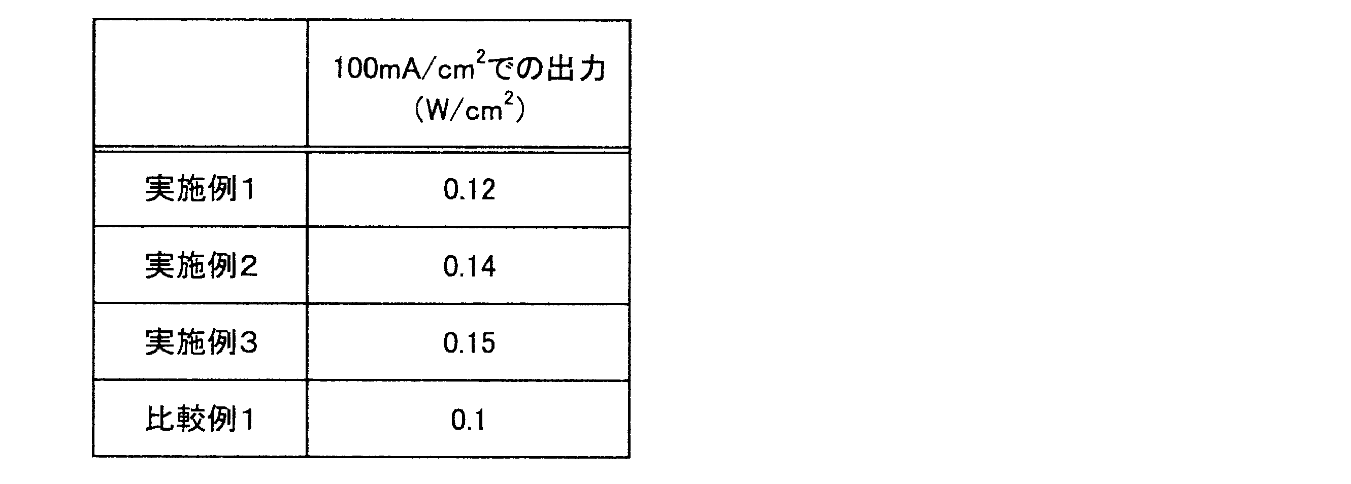
上記実施例1乃至3及び比較例1の正極シートを用い、対極が亜鉛板((株)ニコラ製)、電解液が8Nの水酸化カリウム水溶液のビーカーセルを作製し、放電評価を行った。正極シートの単位面積当たりの電流密度に対し、それぞれの正極における出力を比較した結果を表2に示す。
上記実施例1乃至3及び比較例1の正極シートを用い、対極が亜鉛板((株)ニコラ製)、電解液が8Nの水酸化カリウム水溶液のビーカーセルを作製し、放電評価を行った。正極シートの単位面積当たりの電流密度に対し、それぞれの正極における出力を比較した結果を表2に示す。
[実施例4~8]
液密通気層の構成材料やその混合量を変えた以外は実施例1と同様の操作を繰り返し、実施例4~8の正極シートを得た。各例の正極シートにおける液密通気層の構成材料やその混合量を表3に示す。参考のため、実施例1~3及び比較例1の液密通気層の構成材料や混合量も表3に併記する。また、各実施例及び比較例の正極シートの厚みも表3に併記する。
液密通気層の構成材料やその混合量を変えた以外は実施例1と同様の操作を繰り返し、実施例4~8の正極シートを得た。各例の正極シートにおける液密通気層の構成材料やその混合量を表3に示す。参考のため、実施例1~3及び比較例1の液密通気層の構成材料や混合量も表3に併記する。また、各実施例及び比較例の正極シートの厚みも表3に併記する。
なお、表3中、「CNF」はカーボンナノファイバーを示し、直径40~90nmでアスペクト比が1000以上のものを使用した。「VGCF」は気相成長炭素繊維を示し、直径150nmで繊維長が10~20μmのものを使用した。
[性能評価2]
<引張強さ>
各例の正極シートに関し、JIS7161に準拠して引張強さを測定した。得られた結果を表3に示す。なお、実施例1~3及び比較例1の正極シートについても同様に引張強さを測定した。
<引張強さ>
各例の正極シートに関し、JIS7161に準拠して引張強さを測定した。得られた結果を表3に示す。なお、実施例1~3及び比較例1の正極シートについても同様に引張強さを測定した。
<貫通抵抗>
実施例1~8及び比較例1で得られた正極シートを20mmφの大きさに切り出して接触抵抗を測定した。装置としては、接触抵抗測定器を用いた。そして、2つの電極の間の上記正極シートを挟持し、測定面圧2.0MPaにて1A/cm2の電流を流した際の貫通抵抗値(mΩ・cm2)を測定した。貫通抵抗は、シート面に対して垂直方向の電気抵抗値を示している。そして、値が小さいほど放電ロスを低減できる。得られた結果を表3に示す。
実施例1~8及び比較例1で得られた正極シートを20mmφの大きさに切り出して接触抵抗を測定した。装置としては、接触抵抗測定器を用いた。そして、2つの電極の間の上記正極シートを挟持し、測定面圧2.0MPaにて1A/cm2の電流を流した際の貫通抵抗値(mΩ・cm2)を測定した。貫通抵抗は、シート面に対して垂直方向の電気抵抗値を示している。そして、値が小さいほど放電ロスを低減できる。得られた結果を表3に示す。

表3より、液密通気層に繊維状炭素を添加することにより、引張強さ(機械強度)が向上することが分かる。そのため、繊維状炭素を添加することにより、液密通気層を薄くすることが可能である。例えば、実施例5は実施例4の約半分の厚みで同等の引張強さを達成しているが、薄くなることで抵抗値が小さくなるので、より高出力の正極を得ることが可能である。
特願2012-094529号(出願日:2012年4月18日)及び特願2013-43660号(出願日:2013年3月6日)の全内容は、ここに援用される。
以上、実施例に沿って本発明の内容を説明したが、本発明はこれらの記載に限定されるものではなく、種々の変形及び改良が可能であることは、当業者には自明である。
本発明の空気電池用正極は、導電性炭素とバインダーを用いて触媒層及び液密通気層を形成し、これらを積層して正極を構成している。そのため、正極からの電解液の漏出を抑制することができる。さらに、空気電池の直列接続を容易にし、製造効率や取り扱い性を高めることができる。
1 炭素粒子(導電性炭素)
1a 黒鉛(導電性炭素、骨材炭素)
1b カーボンブラック(導電パス材)
2 バインダー
3 触媒粒子(触媒成分)
10 正極層(空気電池用正極)
11 触媒層
12 液密通気層
1a 黒鉛(導電性炭素、骨材炭素)
1b カーボンブラック(導電パス材)
2 バインダー
3 触媒粒子(触媒成分)
10 正極層(空気電池用正極)
11 触媒層
12 液密通気層
Claims (13)
- 導電性炭素とバインダーと触媒成分とを含有する多孔質層からなる触媒層と、
導電性炭素とバインダーとを含有する多孔質層からなる液密通気層と、
を備え、
前記液密通気層が前記触媒層に積層されることを特徴とする空気電池用正極。 - 前記液密通気層は触媒成分を含有し、
前記触媒成分は、前記液密通気層よりも前記触媒層に多く含有されていることを特徴とする請求項1に記載の空気電池用正極。 - 前記液密通気層のバインダー及び前記触媒層のバインダーは、それぞれ同種の材料からなり、
前記液密通気層のバインダー量は前記触媒層のバインダー量よりも多いことを特徴とする請求項1又は2に記載の空気電池用正極。 - 前記液密通気層のバインダー及び前記触媒層のバインダーは、それぞれ異種の材料からなり、
前記液密通気層のバインダーの軟化温度は前記触媒層のバインダーの軟化温度よりも高いことを特徴とする請求項1又は2に記載の空気電池用正極。 - 前記液密通気層と前記触媒層とが一体成形されていることを特徴とする請求項1乃至4のいずれか一項に記載の空気電池用正極。
- 前記導電性炭素は、層構造の骨格を構成する骨材炭素と、導電通路を形成する導電パス材とを含むことを特徴とする請求項1乃至5のいずれか一項に記載の空気電池用正極。
- 前記導電性炭素は、更に繊維状炭素を含むことを特徴とする請求項6に記載の空気電池用正極。
- 前記骨材炭素は黒鉛であることを特徴とする請求項6又は7に記載の空気電池用正極。
- 前記黒鉛は鱗片状黒鉛であることを特徴とする請求項8に記載の空気電池用正極。
- 前記導電パス材はカーボンブラックであることを特徴とする請求項6乃至9のいずれか一項に記載の空気電池用正極。
- 前記カーボンブラックはアセチレンブラックであることを特徴とする請求項10に記載の空気電池用正極。
- 前記繊維状炭素は、カーボンナノチューブ、カーボンナノファイバー及び気相成長炭素繊維からなる群より選ばれる少なくともいずれか一つであることを特徴とする請求項7に記載の空気電池用正極。
- 請求項1乃至12のいずれか一項に記載の空気電池用正極の製造方法であって、
前記液密通気層を形成するための液密通気層用インクと、前記触媒層を形成するための触媒層用インクとを調製する工程と、
保持体上に前記液密通気層用インクを塗布して乾燥することにより、液密通気層前駆体を形成する工程と、
前記液密通気層前駆体に前記触媒層用インクを塗布して乾燥することにより、触媒層前駆体を形成する工程と、
前記液密通気層前駆体及び前記触媒層前駆体を焼成することにより、前記液密通気層及び前記触媒層を形成する工程と、
前記液密通気層及び前記触媒層を、前記保持体から剥離する工程と、
を有することを特徴とする空気電池用正極の製造方法。
Priority Applications (3)
| Application Number | Priority Date | Filing Date | Title |
|---|---|---|---|
| EP13778564.8A EP2840645B1 (en) | 2012-04-18 | 2013-03-08 | Positive electrode for air battery and process for producing same |
| US14/394,175 US10147954B2 (en) | 2012-04-18 | 2013-03-08 | Positive electrode for air cell and manufacturing method thereof |
| CN201380020116.5A CN104221213B (zh) | 2012-04-18 | 2013-03-08 | 空气电池用正极及其制造方法 |
Applications Claiming Priority (4)
| Application Number | Priority Date | Filing Date | Title |
|---|---|---|---|
| JP2012-094529 | 2012-04-18 | ||
| JP2012094529 | 2012-04-18 | ||
| JP2013-043660 | 2013-03-06 | ||
| JP2013043660A JP6229994B2 (ja) | 2012-04-18 | 2013-03-06 | 空気電池用正極及びその製造方法 |
Publications (1)
| Publication Number | Publication Date |
|---|---|
| WO2013157317A1 true WO2013157317A1 (ja) | 2013-10-24 |
Family
ID=49383285
Family Applications (1)
| Application Number | Title | Priority Date | Filing Date |
|---|---|---|---|
| PCT/JP2013/056419 Ceased WO2013157317A1 (ja) | 2012-04-18 | 2013-03-08 | 空気電池用正極及びその製造方法 |
Country Status (6)
| Country | Link |
|---|---|
| US (1) | US10147954B2 (ja) |
| EP (1) | EP2840645B1 (ja) |
| JP (1) | JP6229994B2 (ja) |
| CN (1) | CN104221213B (ja) |
| TW (1) | TWI470866B (ja) |
| WO (1) | WO2013157317A1 (ja) |
Cited By (2)
| Publication number | Priority date | Publication date | Assignee | Title |
|---|---|---|---|---|
| JP5559927B1 (ja) * | 2013-12-25 | 2014-07-23 | 日本協能電子株式会社 | 空気マグネシウム電池 |
| WO2015146671A1 (ja) * | 2014-03-28 | 2015-10-01 | 日本碍子株式会社 | 金属空気電池用空気極 |
Families Citing this family (10)
| Publication number | Priority date | Publication date | Assignee | Title |
|---|---|---|---|---|
| JP6305192B2 (ja) * | 2014-04-25 | 2018-04-04 | 日本協能電子株式会社 | 空気マグネシウム電池 |
| JP6241946B2 (ja) * | 2014-09-19 | 2017-12-06 | 日本電信電話株式会社 | リチウム空気電池用空気極の製造方法 |
| JP6459034B2 (ja) * | 2014-10-01 | 2019-01-30 | 日産自動車株式会社 | 空気電池用正極及びその製造方法 |
| KR102475889B1 (ko) * | 2015-10-13 | 2022-12-08 | 삼성전자주식회사 | 금속 공기 전지 |
| JP6728776B2 (ja) * | 2016-03-02 | 2020-07-22 | 日立化成株式会社 | 触媒組成物、有機廃水処理装置用電極及び有機廃水処理装置 |
| JP2018063832A (ja) * | 2016-10-12 | 2018-04-19 | Tdk株式会社 | マグネシウム空気電池用正極およびマグネシウム空気電池 |
| JP2022511309A (ja) * | 2018-09-12 | 2022-01-31 | イフバッテリー インコーポレイテッド | 電気化学デバイスに使用するためのセル連続体 |
| EP3874554A4 (en) * | 2018-10-29 | 2022-11-23 | Newsouth Innovations Pty Limited | HYDROGEN BATTERY |
| CN109860633B (zh) * | 2019-02-13 | 2021-10-08 | 苏州擎动动力科技有限公司 | 一种有序介孔催化层及膜电极的制备方法和用途 |
| WO2024192215A1 (en) * | 2023-03-14 | 2024-09-19 | PolyJoule, Inc. | Monolithic high loading electrodes |
Citations (4)
| Publication number | Priority date | Publication date | Assignee | Title |
|---|---|---|---|---|
| JPH06267594A (ja) * | 1993-03-15 | 1994-09-22 | Matsushita Electric Ind Co Ltd | 空気電池 |
| JPH07211322A (ja) * | 1994-01-25 | 1995-08-11 | Matsushita Electric Ind Co Ltd | 空気電極及びその製造方法並びにその電極を有する空気電池 |
| JPH1154130A (ja) | 1997-07-31 | 1999-02-26 | Matsushita Electric Ind Co Ltd | 空気電池用空気極およびその空気電池用空気極の製造法 |
| JP2011181374A (ja) * | 2010-03-02 | 2011-09-15 | Mitsubishi Electric Corp | 固体高分子形燃料電池用膜電極接合体および固体高分子形燃料電池 |
Family Cites Families (17)
| Publication number | Priority date | Publication date | Assignee | Title |
|---|---|---|---|---|
| US4828939A (en) * | 1987-06-01 | 1989-05-09 | Eltech Systems Corporation | Bipolar metal/air battery |
| US5432022A (en) | 1993-11-12 | 1995-07-11 | Dreisbach Electromotive Inc. | Coated cathode for rechargeable metal battery |
| JP3854682B2 (ja) * | 1997-02-13 | 2006-12-06 | アイシン高丘株式会社 | 燃料電池用セパレータ |
| US6127060A (en) * | 1998-06-17 | 2000-10-03 | Aer Energy Resources, Inc. | Recharge catalyst with thin film low corrosion coating, metal-air electrode including said catalyst and methods for making said catalyst and electrode |
| JPWO2003077336A1 (ja) * | 2002-03-14 | 2005-07-07 | 松下電器産業株式会社 | 高分子電解質型燃料電池の製造方法及び、高分子電解質膜型燃料電池 |
| JP4837298B2 (ja) * | 2005-03-10 | 2011-12-14 | 日本ゴア株式会社 | 湿度調整フィルム |
| US20070160898A1 (en) | 2006-01-12 | 2007-07-12 | Matsushita Electric Industrial Co., Ltd. | Air battery and method for producing air electrode for air battery |
| JP2007214114A (ja) * | 2006-01-12 | 2007-08-23 | Matsushita Electric Ind Co Ltd | 空気電池および空気電池用空気極の製造方法 |
| CN200941417Y (zh) | 2006-08-24 | 2007-08-29 | 比亚迪股份有限公司 | 一种锌空气电池 |
| WO2008058165A2 (en) | 2006-11-06 | 2008-05-15 | Akermin, Inc. | Bioanode and biocathode stack assemblies |
| JP2010516017A (ja) * | 2007-01-05 | 2010-05-13 | アケルミン・インコーポレイテッド | バイオアノード及びバイオカソードのスタックアセンブリ |
| JP4458117B2 (ja) * | 2007-06-01 | 2010-04-28 | 株式会社豊田中央研究所 | 非水系空気電池及びその触媒 |
| JP4911155B2 (ja) * | 2008-10-08 | 2012-04-04 | トヨタ自動車株式会社 | 電池電極の製造方法 |
| CN101908661B (zh) * | 2009-06-03 | 2013-02-20 | 北京中航长力能源科技有限公司 | 一种圆柱式锌空气电池的密封方法 |
| JP5392356B2 (ja) * | 2009-12-18 | 2014-01-22 | トヨタ自動車株式会社 | 空気電池用空気極、及び、当該空気極を備えた空気電池 |
| US20110236799A1 (en) * | 2010-02-12 | 2011-09-29 | Revolt Technology Ltd. | Manufacturing methods for air electrode |
| US20120021303A1 (en) * | 2010-07-21 | 2012-01-26 | Steven Amendola | Electrically rechargeable, metal-air battery systems and methods |
-
2013
- 2013-03-06 JP JP2013043660A patent/JP6229994B2/ja active Active
- 2013-03-08 EP EP13778564.8A patent/EP2840645B1/en active Active
- 2013-03-08 CN CN201380020116.5A patent/CN104221213B/zh active Active
- 2013-03-08 WO PCT/JP2013/056419 patent/WO2013157317A1/ja not_active Ceased
- 2013-03-08 US US14/394,175 patent/US10147954B2/en active Active
- 2013-03-08 TW TW102108231A patent/TWI470866B/zh active
Patent Citations (4)
| Publication number | Priority date | Publication date | Assignee | Title |
|---|---|---|---|---|
| JPH06267594A (ja) * | 1993-03-15 | 1994-09-22 | Matsushita Electric Ind Co Ltd | 空気電池 |
| JPH07211322A (ja) * | 1994-01-25 | 1995-08-11 | Matsushita Electric Ind Co Ltd | 空気電極及びその製造方法並びにその電極を有する空気電池 |
| JPH1154130A (ja) | 1997-07-31 | 1999-02-26 | Matsushita Electric Ind Co Ltd | 空気電池用空気極およびその空気電池用空気極の製造法 |
| JP2011181374A (ja) * | 2010-03-02 | 2011-09-15 | Mitsubishi Electric Corp | 固体高分子形燃料電池用膜電極接合体および固体高分子形燃料電池 |
Non-Patent Citations (1)
| Title |
|---|
| See also references of EP2840645A4 |
Cited By (4)
| Publication number | Priority date | Publication date | Assignee | Title |
|---|---|---|---|---|
| JP5559927B1 (ja) * | 2013-12-25 | 2014-07-23 | 日本協能電子株式会社 | 空気マグネシウム電池 |
| WO2015146671A1 (ja) * | 2014-03-28 | 2015-10-01 | 日本碍子株式会社 | 金属空気電池用空気極 |
| JPWO2015146671A1 (ja) * | 2014-03-28 | 2017-04-13 | 日本碍子株式会社 | 金属空気電池用空気極 |
| US10892530B2 (en) | 2014-03-28 | 2021-01-12 | Ngk Insulators, Ltd. | Air electrode for metal-air battery |
Also Published As
| Publication number | Publication date |
|---|---|
| US10147954B2 (en) | 2018-12-04 |
| TW201401634A (zh) | 2014-01-01 |
| EP2840645A4 (en) | 2015-04-08 |
| TWI470866B (zh) | 2015-01-21 |
| EP2840645B1 (en) | 2017-05-10 |
| CN104221213B (zh) | 2017-12-05 |
| JP6229994B2 (ja) | 2017-11-15 |
| JP2013239428A (ja) | 2013-11-28 |
| CN104221213A (zh) | 2014-12-17 |
| EP2840645A1 (en) | 2015-02-25 |
| US20150086883A1 (en) | 2015-03-26 |
Similar Documents
| Publication | Publication Date | Title |
|---|---|---|
| JP6229994B2 (ja) | 空気電池用正極及びその製造方法 | |
| JP6350893B2 (ja) | 空気電池用正極の製造方法 | |
| JP5924530B2 (ja) | 燃料電池用ガス拡散層 | |
| JP5839161B2 (ja) | 燃料電池用ガス拡散層及びその製造方法 | |
| JP5987440B2 (ja) | 燃料電池用微細多孔質層シート及びその製造方法 | |
| CN103797638B (zh) | 空气电池及使用该空气电池的电池组 | |
| WO2010035815A1 (ja) | 燃料電池用ガス拡散層 | |
| US20150132668A1 (en) | Conductive porous layer for battery, and manufacturing method for same | |
| JP6119865B2 (ja) | 空気電池及び組電池 | |
| JP6299247B2 (ja) | 空気電池用ユニット及び空気電池 | |
| JP6222519B2 (ja) | 空気電池用正極及びその製造方法 | |
| JP6260767B2 (ja) | 空気電池用正極及びその製造方法 | |
| JP6434691B2 (ja) | 空気電池用正極及びその製造方法 | |
| JP6459034B2 (ja) | 空気電池用正極及びその製造方法 | |
| JP6249346B2 (ja) | 電極構造体及びその製造方法 | |
| JP6468476B2 (ja) | 空気電池用正極の製法方法 | |
| JP6543451B2 (ja) | 空気電池電極用複合多孔質体及びこれを用いた空気電池電極体 | |
| JP2018170220A (ja) | 空気電池 | |
| JP2017174795A (ja) | 扁平形電池 | |
| JP2014175285A (ja) | ガス拡散層、膜電極接合体、燃料電池、及びガス拡散層の製造方法 | |
| JP2019129022A (ja) | 空気極、空気極の製造方法、及び金属空気電池 | |
| JP2008103134A (ja) | 空気電池 |
Legal Events
| Date | Code | Title | Description |
|---|---|---|---|
| 121 | Ep: the epo has been informed by wipo that ep was designated in this application |
Ref document number: 13778564 Country of ref document: EP Kind code of ref document: A1 |
|
| WWE | Wipo information: entry into national phase |
Ref document number: 14394175 Country of ref document: US |
|
| NENP | Non-entry into the national phase |
Ref country code: DE |
|
| REEP | Request for entry into the european phase |
Ref document number: 2013778564 Country of ref document: EP |
|
| WWE | Wipo information: entry into national phase |
Ref document number: 2013778564 Country of ref document: EP |