WO2013157533A1 - Procédé et dispositif de production d'article jetable pouvant être porté - Google Patents
Procédé et dispositif de production d'article jetable pouvant être porté Download PDFInfo
- Publication number
- WO2013157533A1 WO2013157533A1 PCT/JP2013/061252 JP2013061252W WO2013157533A1 WO 2013157533 A1 WO2013157533 A1 WO 2013157533A1 JP 2013061252 W JP2013061252 W JP 2013061252W WO 2013157533 A1 WO2013157533 A1 WO 2013157533A1
- Authority
- WO
- WIPO (PCT)
- Prior art keywords
- panels
- flow direction
- panel
- pitch
- widening
- Prior art date
- Legal status (The legal status is an assumption and is not a legal conclusion. Google has not performed a legal analysis and makes no representation as to the accuracy of the status listed.)
- Ceased
Links
Images


Classifications
-
- A—HUMAN NECESSITIES
- A61—MEDICAL OR VETERINARY SCIENCE; HYGIENE
- A61F—FILTERS IMPLANTABLE INTO BLOOD VESSELS; PROSTHESES; DEVICES PROVIDING PATENCY TO, OR PREVENTING COLLAPSING OF, TUBULAR STRUCTURES OF THE BODY, e.g. STENTS; ORTHOPAEDIC, NURSING OR CONTRACEPTIVE DEVICES; FOMENTATION; TREATMENT OR PROTECTION OF EYES OR EARS; BANDAGES, DRESSINGS OR ABSORBENT PADS; FIRST-AID KITS
- A61F13/00—Bandages or dressings; Absorbent pads
- A61F13/15—Absorbent pads, e.g. sanitary towels, swabs or tampons for external or internal application to the body; Supporting or fastening means therefor; Tampon applicators
- A61F13/45—Absorbent pads, e.g. sanitary towels, swabs or tampons for external or internal application to the body; Supporting or fastening means therefor; Tampon applicators characterised by the shape
- A61F13/49—Absorbent pads, e.g. sanitary towels, swabs or tampons for external or internal application to the body; Supporting or fastening means therefor; Tampon applicators characterised by the shape specially adapted to be worn around the waist, e.g. diapers, nappies
- A61F13/49058—Absorbent pads, e.g. sanitary towels, swabs or tampons for external or internal application to the body; Supporting or fastening means therefor; Tampon applicators characterised by the shape specially adapted to be worn around the waist, e.g. diapers, nappies characterised by the modular concept of constructing the diaper
-
- A—HUMAN NECESSITIES
- A61—MEDICAL OR VETERINARY SCIENCE; HYGIENE
- A61F—FILTERS IMPLANTABLE INTO BLOOD VESSELS; PROSTHESES; DEVICES PROVIDING PATENCY TO, OR PREVENTING COLLAPSING OF, TUBULAR STRUCTURES OF THE BODY, e.g. STENTS; ORTHOPAEDIC, NURSING OR CONTRACEPTIVE DEVICES; FOMENTATION; TREATMENT OR PROTECTION OF EYES OR EARS; BANDAGES, DRESSINGS OR ABSORBENT PADS; FIRST-AID KITS
- A61F13/00—Bandages or dressings; Absorbent pads
- A61F13/15—Absorbent pads, e.g. sanitary towels, swabs or tampons for external or internal application to the body; Supporting or fastening means therefor; Tampon applicators
- A61F13/15577—Apparatus or processes for manufacturing
- A61F13/15756—Applying tabs, strips, tapes, loops; Knotting the ends of pads
-
- A—HUMAN NECESSITIES
- A61—MEDICAL OR VETERINARY SCIENCE; HYGIENE
- A61F—FILTERS IMPLANTABLE INTO BLOOD VESSELS; PROSTHESES; DEVICES PROVIDING PATENCY TO, OR PREVENTING COLLAPSING OF, TUBULAR STRUCTURES OF THE BODY, e.g. STENTS; ORTHOPAEDIC, NURSING OR CONTRACEPTIVE DEVICES; FOMENTATION; TREATMENT OR PROTECTION OF EYES OR EARS; BANDAGES, DRESSINGS OR ABSORBENT PADS; FIRST-AID KITS
- A61F13/00—Bandages or dressings; Absorbent pads
- A61F13/15—Absorbent pads, e.g. sanitary towels, swabs or tampons for external or internal application to the body; Supporting or fastening means therefor; Tampon applicators
- A61F13/45—Absorbent pads, e.g. sanitary towels, swabs or tampons for external or internal application to the body; Supporting or fastening means therefor; Tampon applicators characterised by the shape
- A61F13/49—Absorbent pads, e.g. sanitary towels, swabs or tampons for external or internal application to the body; Supporting or fastening means therefor; Tampon applicators characterised by the shape specially adapted to be worn around the waist, e.g. diapers, nappies
-
- A—HUMAN NECESSITIES
- A61—MEDICAL OR VETERINARY SCIENCE; HYGIENE
- A61F—FILTERS IMPLANTABLE INTO BLOOD VESSELS; PROSTHESES; DEVICES PROVIDING PATENCY TO, OR PREVENTING COLLAPSING OF, TUBULAR STRUCTURES OF THE BODY, e.g. STENTS; ORTHOPAEDIC, NURSING OR CONTRACEPTIVE DEVICES; FOMENTATION; TREATMENT OR PROTECTION OF EYES OR EARS; BANDAGES, DRESSINGS OR ABSORBENT PADS; FIRST-AID KITS
- A61F13/00—Bandages or dressings; Absorbent pads
- A61F13/15—Absorbent pads, e.g. sanitary towels, swabs or tampons for external or internal application to the body; Supporting or fastening means therefor; Tampon applicators
- A61F13/56—Supporting or fastening means
- A61F13/5622—Supporting or fastening means specially adapted for diapers or the like
- A61F13/5633—Supporting or fastening means specially adapted for diapers or the like open type diaper
-
- B—PERFORMING OPERATIONS; TRANSPORTING
- B65—CONVEYING; PACKING; STORING; HANDLING THIN OR FILAMENTARY MATERIAL
- B65G—TRANSPORT OR STORAGE DEVICES, e.g. CONVEYORS FOR LOADING OR TIPPING, SHOP CONVEYOR SYSTEMS OR PNEUMATIC TUBE CONVEYORS
- B65G47/00—Article or material-handling devices associated with conveyors; Methods employing such devices
- B65G47/22—Devices influencing the relative position or the attitude of articles during transit by conveyors
- B65G47/26—Devices influencing the relative position or the attitude of articles during transit by conveyors arranging the articles, e.g. varying spacing between individual articles
- B65G47/30—Devices influencing the relative position or the attitude of articles during transit by conveyors arranging the articles, e.g. varying spacing between individual articles during transit by a series of conveyors
- B65G47/32—Applications of transfer devices
-
- B—PERFORMING OPERATIONS; TRANSPORTING
- B65—CONVEYING; PACKING; STORING; HANDLING THIN OR FILAMENTARY MATERIAL
- B65G—TRANSPORT OR STORAGE DEVICES, e.g. CONVEYORS FOR LOADING OR TIPPING, SHOP CONVEYOR SYSTEMS OR PNEUMATIC TUBE CONVEYORS
- B65G47/00—Article or material-handling devices associated with conveyors; Methods employing such devices
- B65G47/74—Feeding, transfer, or discharging devices of particular kinds or types
- B65G47/84—Star-shaped wheels or devices having endless travelling belts or chains, the wheels or devices being equipped with article-engaging elements
-
- B—PERFORMING OPERATIONS; TRANSPORTING
- B65—CONVEYING; PACKING; STORING; HANDLING THIN OR FILAMENTARY MATERIAL
- B65H—HANDLING THIN OR FILAMENTARY MATERIAL, e.g. SHEETS, WEBS, CABLES
- B65H35/00—Delivering articles from cutting or line-perforating machines; Article or web delivery apparatus incorporating cutting or line-perforating devices, e.g. adhesive tape dispensers
- B65H35/04—Delivering articles from cutting or line-perforating machines; Article or web delivery apparatus incorporating cutting or line-perforating devices, e.g. adhesive tape dispensers from or with transverse cutters or perforators
- B65H35/08—Delivering articles from cutting or line-perforating machines; Article or web delivery apparatus incorporating cutting or line-perforating devices, e.g. adhesive tape dispensers from or with transverse cutters or perforators from or with revolving, e.g. cylinder, cutters or perforators
-
- B—PERFORMING OPERATIONS; TRANSPORTING
- B65—CONVEYING; PACKING; STORING; HANDLING THIN OR FILAMENTARY MATERIAL
- B65H—HANDLING THIN OR FILAMENTARY MATERIAL, e.g. SHEETS, WEBS, CABLES
- B65H2220/00—Function indicators
- B65H2220/09—Function indicators indicating that several of an entity are present
-
- B—PERFORMING OPERATIONS; TRANSPORTING
- B65—CONVEYING; PACKING; STORING; HANDLING THIN OR FILAMENTARY MATERIAL
- B65H—HANDLING THIN OR FILAMENTARY MATERIAL, e.g. SHEETS, WEBS, CABLES
- B65H2301/00—Handling processes for sheets or webs
- B65H2301/40—Type of handling process
- B65H2301/44—Moving, forwarding, guiding material
- B65H2301/445—Moving, forwarding, guiding material stream of articles separated from each other
- B65H2301/4451—Moving, forwarding, guiding material stream of articles separated from each other forming a stream or streams of separated articles
- B65H2301/44512—Moving, forwarding, guiding material stream of articles separated from each other forming a stream or streams of separated articles forming parallel streams of separated articles
-
- B—PERFORMING OPERATIONS; TRANSPORTING
- B65—CONVEYING; PACKING; STORING; HANDLING THIN OR FILAMENTARY MATERIAL
- B65H—HANDLING THIN OR FILAMENTARY MATERIAL, e.g. SHEETS, WEBS, CABLES
- B65H2301/00—Handling processes for sheets or webs
- B65H2301/40—Type of handling process
- B65H2301/44—Moving, forwarding, guiding material
- B65H2301/445—Moving, forwarding, guiding material stream of articles separated from each other
- B65H2301/4452—Regulating space between separated articles
- B65H2301/44522—Varying space between separated articles
-
- B—PERFORMING OPERATIONS; TRANSPORTING
- B65—CONVEYING; PACKING; STORING; HANDLING THIN OR FILAMENTARY MATERIAL
- B65H—HANDLING THIN OR FILAMENTARY MATERIAL, e.g. SHEETS, WEBS, CABLES
- B65H2301/00—Handling processes for sheets or webs
- B65H2301/40—Type of handling process
- B65H2301/44—Moving, forwarding, guiding material
- B65H2301/445—Moving, forwarding, guiding material stream of articles separated from each other
- B65H2301/4455—Diverting a main stream into part streams
- B65H2301/44552—Diverting a main stream into part streams by alternatively directing articles following each other to appropriate part stream
-
- B—PERFORMING OPERATIONS; TRANSPORTING
- B65—CONVEYING; PACKING; STORING; HANDLING THIN OR FILAMENTARY MATERIAL
- B65H—HANDLING THIN OR FILAMENTARY MATERIAL, e.g. SHEETS, WEBS, CABLES
- B65H2301/00—Handling processes for sheets or webs
- B65H2301/40—Type of handling process
- B65H2301/44—Moving, forwarding, guiding material
- B65H2301/447—Moving, forwarding, guiding material transferring material between transport devices
- B65H2301/4472—Suction grippers, e.g. moved in paths enclosing an area
-
- B—PERFORMING OPERATIONS; TRANSPORTING
- B65—CONVEYING; PACKING; STORING; HANDLING THIN OR FILAMENTARY MATERIAL
- B65H—HANDLING THIN OR FILAMENTARY MATERIAL, e.g. SHEETS, WEBS, CABLES
- B65H2406/00—Means using fluid
- B65H2406/30—Suction means
- B65H2406/34—Suction grippers
- B65H2406/345—Rotary suction grippers
-
- B—PERFORMING OPERATIONS; TRANSPORTING
- B65—CONVEYING; PACKING; STORING; HANDLING THIN OR FILAMENTARY MATERIAL
- B65H—HANDLING THIN OR FILAMENTARY MATERIAL, e.g. SHEETS, WEBS, CABLES
- B65H2801/00—Application field
- B65H2801/57—Diaper manufacture
Definitions
- the present invention relates to a manufacturing method and a manufacturing apparatus for disposable wearing articles.
- Patent Document 1 As a method for manufacturing this type of wearing article, a method is known in which a pair of panels are joined to the left and right of the waist of the diaper body (Patent Document 1).
- JP2010-530269A (FIGS. 1 to 6)
- the pair of panels are positioned at the same position in the vertical direction of the main body of the diaper by controlling the conveyance speed of the pair of panels together with the rotation speed of the alignment roller.
- Such speed control generally inevitably complicates the mechanism for speed control.
- one object of the present invention is to provide a manufacturing method and a manufacturing apparatus for a disposable wearing article in which the mechanism for arranging the panels at the same position in the longitudinal direction of the main body is less complicated.
- the manufacturing method of the present invention is a method for manufacturing a disposable wearing article in which a set of panels are joined to each other at the same position in the longitudinal direction of the main body and on both the left and right sides in the waistline direction.
- a cutting step in which a plurality of panels are generated one after another by cutting one after another along a virtual cutting line extending in the width direction perpendicular to the flow direction at the front end of the flow direction of the continuous web continuous in the flow direction;
- a widening step of widening a gap in the width direction between a pair of panels adjacent to each other in the flow direction among the plurality of panels;
- a first axis of a first roller that receives and holds one panel of the set of panels spaced apart from each other in the width direction, and a second axis that receives and holds the other panel of the set of panels.
- extending in the width direction orthogonal to the flow direction means including not only extending in the width direction but also extending in both the width direction and the flow direction.
- the manufacturing apparatus of the present invention is a manufacturing apparatus for disposable wearing articles in which a pair of panels are joined to each other at the same position in the longitudinal direction of the main body and on both the left and right sides in the waistline direction.
- a cutter that sequentially cuts the leading end portion of the continuous web in the flow direction along a virtual cutting line extending in the width direction orthogonal to the flow direction to generate a plurality of panels one after another;
- a widening drum that widens the gap in the width direction between a pair of panels adjacent to each other in the flow direction among the plurality of panels;
- a first axis of a first roller that receives and holds one panel of the set of panels spaced apart from each other in the width direction, and a second axis that receives and holds the other panel of the set of panels.
- the second axis of the roller is arranged to be offset from each other in the flow direction of the panel, and the first and second rollers receive the panels at first and second receiving positions spaced from each other along the flow direction. Furthermore, the phase wheel which arrange
- the first axis of the first roller and the second axis of the second roller are offset from each other by a predetermined offset amount ⁇ . Therefore, among the rollers, the first roller offset to the downstream side. Receives the panel from the widening drum at a position that is substantially equal to the offset amount ⁇ from the second roller.
- the panel is disposed in the main body.
- the first roller offset to the downstream side causes the panel to be positioned upstream in the flow direction of the main body by the offset amount ⁇ .
- the second roller arranges the panel in the main body part downstream in the flow direction of the main body part by the offset amount ⁇ . Therefore, also here, the panel arranged by the first roller is delayed by approximately equal to the offset amount ⁇ compared to that of the second roller.
- another object of the present invention is to provide a manufacturing method and a manufacturing apparatus for a disposable worn article in which the holding position of the panel is shifted or the panel is not easily wrinkled.
- the manufacturing method of the present invention in another aspect, is a method for manufacturing a disposable wearing article in which a set of panels is joined to both the left and right sides of the body portion in the waistline direction.
- a cutting step in which a plurality of panels are generated one after another by cutting one after another along a virtual cutting line extending in the width direction perpendicular to the flow direction at the front end of the flow direction of the continuous web continuous in the flow direction;
- a first re-pitch step of widening an interval in the flow direction between the plurality of panels; After the first re-pitch step, a widening step of widening the interval in the width direction between a pair of adjacent panels among the plurality of panels;
- a disposing step of disposing each of the set of panels on both sides of the main body after the widening step.
- the manufacturing apparatus of the present invention in another aspect, is a manufacturing apparatus for a disposable wearing article in which a pair of panels are joined to both the left and right sides of the body portion in the waistline direction.
- a cutter that sequentially cuts the leading end portion of the continuous web in the flow direction along a virtual cutting line extending in the width direction orthogonal to the flow direction to generate a plurality of panels one after another;
- a first re-pitch drum that widens the interval between the plurality of panels in the flow direction;
- a widening drum that is arranged downstream of the first re-pitch drum, and widens the interval in the width direction between a pair of adjacent panels among the plurality of panels;
- a phase wheel that is disposed downstream of the widening drum and that disposes each of the pair of panels on both sides of the main body.
- the panel before the panel cut from the continuous web is moved in the width direction, the panel is moved in the flow direction by the first re-pitch step, thereby increasing the interval between adjacent panels. Therefore, there is no possibility that the panels interfere with each other when the panels are moved in the width direction to widen the interval between the panels. Therefore, there is no possibility that the holding position of the panel is shifted or wrinkles due to interference between the panels.
- “extending in the width direction” may be set such that a virtual cutting line is set along a side perpendicular to the flow direction, or may be set in an oblique direction inclined with respect to the width direction. Furthermore, it means that a quadratic curve or a cubic curve may be used instead of a straight line. For example, even if a virtual cutting line is set along the side, the interval in the flow direction between the panels is expanded in advance by the first re-pitch process, so that the panels are expanded during the widening process. Are not likely to interfere with each other due to wind pressure or the like.
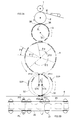
- FIG. 1 is a conceptual diagram showing a part of the process of Example 1 of the method for manufacturing a worn article according to the present invention.
- FIG. 2 is a conceptual diagram showing the remainder of the process.
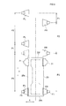
- FIG. 3A is a schematic side view showing the manufacturing apparatus of the present invention, and FIG. 3B is a plan view in which a panel is arranged on the main body.
- FIG. 4A is a schematic plan view showing the phase wheel, and FIGS. 4B and 4C are schematic side views showing the second and first rollers, respectively.
- FIG. 5 is a schematic perspective view showing the second re-pitch drum and the phase wheel.
- 6A and 6B are schematic perspective views showing a receiving process in which the first and second rollers receive the panel.
- FIG. 7A and 7B are schematic perspective views showing an arrangement process in which the first and second rollers arrange the panel on the main body.
- FIG. 8 is a conceptual diagram showing a part of the process of the second embodiment.
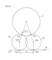
- FIG. 9 is a side view showing the principle of the present invention.
- the manufacturing method according to the one aspect further includes a re-pitch step of expanding a space in the flow direction between a pair of panels adjacent to each other in the flow direction among the plurality of panels.
- the panels can be continuously arranged with respect to the adjacent main body portions.
- the rotation speeds of the plurality of pads holding the panel between the receiving step and the arranging step are periodically changed by the number of the pads per rotation in accordance with the size of the wearing article. Further comprising a shifting step.
- a plurality of sizes of wearing articles can be manufactured with a single manufacturing apparatus by electrical control using a servo motor.
- each of the first and second rollers includes a plurality of first and second pads that hold the panel, and the first pad and the second pad Are spaced apart from each other in the width direction, and the first axis that is the rotation center of the first pad and the second axis that is the rotation center of the second pad are separated from each other in the flow direction.
- the rotation radii of the first pad and the second pad are the same.
- it further includes a re-pitch drum that is arranged between the cutter and the widening drum and widens the interval in the flow direction between a pair of panels adjacent to each other in the flow direction among the plurality of panels. .
- the panels can be continuously arranged on a plurality of main body portions.
- the rotation speed of the plurality of pads holding the panel is periodically changed by the number of the pads per rotation in accordance with the size of the wearing article between the receiving and the arrangement of the rollers.
- a shift control device is further provided.
- a plurality of types of wearing articles can be manufactured with a single manufacturing apparatus by electrical control using a servo motor.
- the virtual cutting line is non-parallel to the width direction, and the leading end portions of the continuous web are successively arranged along the non-parallel cutting line in the cutting step. Cut to produce the panel.
- “Non-parallel” is a concept that excludes the case where a virtual cutting line is set along a horizontal direction perpendicular to the flow direction. That is, it means that the virtual cutting line may be set in an oblique direction inclined with respect to the width direction, and may be a quadratic curve or a cubic curve instead of a straight line.
- a second re-pitch step of expanding a set interval between the set of panels spaced apart from each other in the flow direction and another set of panels adjacent to the set of panels is further performed.
- the set interval between one set of panels and the next set of adjacent panels can be matched with or close to the interval between adjacent main body portions. That is, in the arrangement step, a set of panels can be arranged on each main body portion so as to match (or approach) the interval between adjacent main body portions conveyed in the flow direction.
- the virtual cutting line is non-parallel to the width direction, and the tip portion of the continuous web is successively cut by the cutter along the non-parallel cutting line.
- the panel is generated.
- the set interval between a pair of panels arranged downstream of the first re-pitch drum and spaced apart from each other in the flow direction and another set of panels adjacent to the set of panels is expanded.
- a second re-pitch drum is further provided.
- the second re-pitch drum can widen the set interval between one set of panels and the next set of panels.
- the phase wheel is disposed downstream of the second re-pitch drum, and receives a plurality of sets of panels with the increased set interval one after another, and further increases the set interval after the reception.
- the diaper includes an absorbent main body 20, a pair of side panels PL and PR joined to the main body 20, and a pair of ear members 21 and 21.
- the said main-body part 20 covers a wearer's front waist area, a crotch area, and a back waist area at the time of wear.
- the main body portion 20 includes a front body portion 20f, a crotch portion 20c, and a rear body portion 20b corresponding to the respective regions.
- the panels PL and PR are respectively positioned between the front and rear trunk portions 20f and 20b when worn. Panels PL and PR are respectively joined to the left side and the right side of the end in the longitudinal direction Y of main body 20. The panels PL and PR are joined to the rear trunk 20b in a state of protruding from the left and right of the rear trunk 20b of the main body 20, for example. Panels PL and PR may be joined to front body portion 20f.
- the ear member 21 is joined to the left and right of the front body portion 20 f of the main body portion 20.
- the ear member 21 may be omitted.
- Panels PL and PR may be formed, for example, by sandwiching an elastic yarn (an example of an elastic member) between two nonwoven fabrics. As shown in FIG. 2, the panels PL and PR may be in a contracted state in which a gather is formed by contracting the elastic yarn in the waistline direction X in an unloaded state.
- the method disclosed in JP63-243309A may be used as a method of arranging elastic yarns on the panels PL, PR.
- the panels PL and PR may be formed of a stretchable nonwoven fabric having stretchability that does not have the elastic yarn.
- a first surface fastener (an example of a joining element) F1 may be joined to the inner surface side (the side that comes into contact with the skin when worn) of the panels PL and PR.
- a second surface fastener (not shown) that can be surface-bonded to the first surface fastener F1 on the outer surface side (the side exposed to the outside when worn) of the main body portion 20 on the front body portion 20f side. ) May be joined.
- the side panel PL, PR is wrapped around the wearer's torso while grasping the ear member 21, and the first surface fastener F1 of the side panel PL, PR is joined to the second surface fastener, whereby the diaper is It is worn by the wearer.
- the said 2nd surface fastener can be abbreviate
- the main body 20 and the panels (PR, PL) may be provided with an adhesive tape and a portion bonded to the adhesive tape, instead of the hook-and-loop fastener.
- the main body 20 has, for example, a pair of cuffs (leak barriers) that contact the surface of the wearer, a liquid-permeable top sheet, an absorbent core 24 that absorbs liquid, and liquid impermeability.
- a back sheet or the like may be provided.
- the main-body part 20 may be provided with the leg elastic yarn, for example.
- the cuff may be omitted, or may be provided with an elastic yarn that contracts the cuff in the Y direction.
- the back sheet may be a sheet having air permeability and waterproofness. The back sheet may be a stretchable sheet.
- the manufacturing apparatus includes a cutter 1, an anvil roll 2, a first re-pitch drum 3, a widening drum (second re-pitch drum) 4, a phase wheel 5, and a conveying device 6.
- the cutter 1 moves the leading end in the flow direction Y of the continuous web W introduced onto the anvil roll 2 from the supply device 11 of the continuous web W continuous in the flow direction Y in the flow direction Y.
- a plurality of panels PL and PR are sequentially generated by cutting one after another at a predetermined interval along a virtual cutting line C extending in the orthogonal width direction X.
- the continuous web W is cut
- the virtual cutting line C is non-parallel to the width direction X, and the front end portions of the continuous web W are successively cut by the cutter 1 along the non-parallel cutting line C, and the panels PL, A PR may be generated.
- the panels PL and PR may have a trapezoidal shape, and the panels PL and PR may have a point-symmetric shape with respect to the point O on the center line CL.
- the shapes of the panels PR and PL may be parallelograms, squares or rectangles.
- the first re-pitch drum 3 has a plurality of left and right pads 3L and 3R that approach each other after the interval is widened during one rotation.
- the interval P0 in the flow direction Y of the plurality of panels PL and PR in FIG. 1 is expanded to the interval P1.
- the left and right pads 3L and 3R may have a trapezoidal shape that approximates the shape of the panels PL and PR.
- the first re-pitch drum 3 may be a drum disclosed in US 2006/0151093 A1 or JP 63-317576A, and all of the description is incorporated here.
- the widening drum 4 in FIG. 3A is arranged downstream of the first re-pitch drum 3, and sets the interval in the width direction X between a pair of the panels PL, PR adjacent to each other among the plurality of panels PL, PR. spread.
- the widening drum 4 widens a set interval P2 between a set of panels PL and PR spaced apart from each other in the flow direction Y and another set of panels PL and PR adjacent to the set of panels PL and PR.
- a second re-pitch drum may be configured.
- the widening drum 4 shown in FIG. 5 has a plurality of left and right pads 4L and 4R.
- the pads 4L and 4R return to the original state after the interval between the width direction X and the flow direction Y is widened while the widening drum 4 is rotated once. That is, while the widening drum 4 rotates in the circumferential direction R, the right pad 4R moves to one side of the widening drum 4, and the left pad 4L moves to the other side of the widening drum 4 so that the pads 4R and 4L.
- the width direction X of the pads 4R, 4R (4L, 4L) adjacent to each other in the flow direction Y are widened by the widening drum 4 constituting the second re-pitch drum.
- the interval between the panels PL and PL (PR, PR) adjacent in the flow direction is expanded from (2 * P1) to P2.
- the width interval between the right and left pads 4R and 4L is set to receive the panels PR and PL again.
- the original state is restored, and the distance in the flow direction between the re-pitched pads is also restored.
- the structure of the widening drum 4 for example, the structure of a drum disclosed in JP 2006-230438 A may be adopted, and the entire description thereof is incorporated here.
- the phase wheel 5 of FIG. 3A includes first and second rollers 51 and 52 disposed downstream of the widening drum 4, and each of the pair of panels PR and PL is disposed on the main body 20.
- a first axis 51S of the first roller 51 that receives and holds one of the panels PR, PR, which are spaced apart from each other in the width direction X in FIG. 5, and the set of panels PL, PR.
- the second axis 52S of the second roller 52 that receives and holds the other panel PL is offset (eccentric) by ⁇ in the flow direction Y of the panels PL and PR.
- the first and second rollers 51 and 52 have a plurality of first and second pads 51P and 52P for holding the panels PL and PR, respectively.
- the first pad 51P and the second pad 52P are spaced apart from each other in the width direction X, and the first axis 51S that is the rotation center of the first pad 51P and the rotation center of the second pad 52P.
- the first pad 51P and the second pad 52P that receive these panels respectively downstream are displaced from each other in the circumferential position.
- the first and second rollers 51 and 52 receive the panels PL and PR at first and second receiving positions P11 and P12 that are spaced apart from each other along the flow direction Y. Furthermore, the first and second rollers 51 , 52 are arranged on both sides of the main body 20 as shown in FIGS. 7A and 7B at the first and second transfer positions P21 and P22 in FIG. To do.
- the pair of panels PL and PR are arranged at the same position (level) in the flow direction Y of the main body 20. That is, they are arranged so as to be symmetrical positions.
- the said conveying apparatus 6 conveys the main-body part 20 along a horizontal surface, for example.
- the manufacturing method of the present embodiment includes a cutting process, a first re-pitch process, a widening process, a second re-pitch process, a receiving process and an arrangement process described below.
- a virtual cutting in which the leading end of the continuous web W continuous in the flow direction Y on the anvil roll 2 extends in the width direction X by the cutter 1.
- a plurality of panels PL and PR are generated one after another by being cut one after another at a predetermined interval along the line C.
- the interval in the flow direction Y in FIG. 1 is P0 to P1 in FIG.
- the first re-pitch step that is expanded to the above is executed.
- the panels PL and PR in FIG. 1 are transferred from the first re-pitch drum 3 in FIG. 3A to the widening drum 4 after the first re-pitch step.
- a widening step is performed in which a space in the width direction X between a pair of adjacent panels PL, PR among the plurality of panels PL, PR in FIG. 1 is widened.
- a second re-pitch that widens a set interval between a set of panels PL and PR spaced apart from each other in the flow direction Y and another set of panels PL and PR adjacent to the set of panels.
- the process is executed. That is, the interval between the panels PR (PL) adjacent in the flow direction Y is expanded to P2.
- the pair of panels PL and PR have a phase shift (phase difference) of the pitch P1 in FIG.
- a receiving step is performed in which the first and second rollers 51 and 52 of the phase wheel 5 receive the panels PR and PL from the widening drum 4 of FIG.
- the step of disposing each of the panels PR, PL on the main body 20 is executed.
- the panel PR held on the right pad 4R of the widening drum 4 in FIG. 5 is received as shown by applying the halftone dots in FIG. 6A to the first pad 51P of the first roller 51.
- the panel PL held on the left pad 4L of the widening drum 4 of FIG. 5 is received as shown by applying the halftone dot of FIG. 6B to the second pad 52P of the second roller 52.
- the first and second pads 51P and 52P are provided corresponding to the panels PR and PL, but the pads are not shown in FIGS. 6 and 7 for the sake of drawing.
- the phase difference P1 present in the pair of panels PL and PR at the time of reception is such that the second reception position P12 is positioned upstream of the flow direction Y by the offset amount ⁇ compared to the first reception position P11. Therefore, it is approximately (P1- ⁇ ). That is, the phase difference between the pair of panels PL and PR becomes small.
- the arranging step shown in FIGS. 7A and 7B is performed. That is, in this arrangement step, the panels PR and PL are separated from each other in the flow direction Y from the first and second rollers 51 and 52 at the first and second transfer positions P21 and P22 (FIG. 3A). Arranged on both sides of the main body 20. As shown in FIG. 7A, after the right panel PR is arranged from the first roller 51 on one side of the main body portion 20 at the first transfer position P21, as shown in FIG. The left panel PL from the two rollers 52 is disposed on the other side of the main body 20 at the second transfer position P22.
- the second transfer position P22 exists downstream of the first transfer position P21 by the offset amount ⁇ . Therefore, the phase difference between the set of panels PL and PR is approximately (P1 ⁇ ) to approximately (P1 ⁇ 2 * ⁇ ), and is set to P1 ⁇ 2 * ⁇ .
- the PR phase difference is approximately zero. That is, the pair of panels PL and PR are disposed on both sides of the main body 20 at substantially the same position in the longitudinal direction Y of the main body 20.
- the difference between the offset amount C ⁇ ⁇ and the offset amount ⁇ is adjusted to an appropriate value on site.
- a plurality of types of main body portions 20 can be manufactured by a single manufacturing apparatus without changing parts.
- the length of the main body 20 is different for each size of the main body 20. Therefore, it is necessary to change the interval (pitch) P2 between the pair of adjacent panels PL and PR to P3.
- a shift control device (not shown) is provided in this embodiment.
- the speed change control device controls, for example, a servo motor, and the rotational speeds of the plurality of pads 51P and 52P that hold the panels PL and PR between the reception and arrangement of the rollers 51 and 52 are the size of the worn article. Accordingly, the number of the pads 51P and 52P is periodically changed per rotation.
- the phase wheel 5 is disposed downstream of the widening drum 4 and receives a plurality of sets of panels PL and PR with a wide set interval one after another.
- the set interval is further expanded from P2 to P3.
- Such a periodic shifting method uses a main motor and an auxiliary servo motor, and is disclosed in, for example, JP2002-35027A, the entire description of which is incorporated herein.
- the present embodiment includes a third re-pitch step.
- a third re-pitch step a plurality of sets of panels PL and PR having the set intervals expanded after the second re-pitch step are successively transferred from the widening drum 4 to the phase wheel 5.
- the set interval is further expanded from P2 to P3. That is, the first and second rollers 51 and 52 are rotated once by the rotation speed of the plurality of pads 51P and 52P holding the panels PL and PR between the receiving process and the arranging process in accordance with the size of the wearing article.
- a speed change process in which the speed is periodically changed by the number of the pads 51P and 52P (three times in the case of FIG. 4).
- the rotation radii of the first pad 51 and the second pad 52 may be the same size, but the rotation radii may be different from each other.
- the conveying surface of the conveying device 6 will be inclined with respect to the horizontal.
- rollers and drums 1 to 5 in FIG. 3A may be arranged horizontally instead of vertically to reduce the load accumulated and applied to the shaft.
- the conveying surface of the conveying device 6 is set to be vertical. May be.
- phase wheel 5 may not be provided.
- a wearing article may be a diaper type or a pants type. Accordingly, such changes and modifications are to be construed as within the scope of the present invention as defined by the claims.
- This invention can be utilized for manufacture of the manufacturing method and manufacturing apparatus of a disposable wearing article.
- Cutter 11 Supply device 2: Anvil roll 20: Absorbent main body 20b: Rear trunk 20c: Crotch 20f: Front trunk 2 21: Ear member 3: First re-pitch drum 3L, 3R: Left and right pad 4: Widening drum (second re-pitch drum) 4L, 4R: Left and right pad 5: Phase wheel 51, 52: First And second roller 51S: first axis 52S: second axis 51P, 52P: first and second pads 6: conveying device C: cutting line CL: center line F1: first surface fastener O: point PL, PR: side Panels P1, P1: Interval P2: Assembly interval P11, P12: First and second receiving positions P21, P22: First and second transfer positions X: Width direction Y: Flow direction W: Continuous web
Landscapes
- Health & Medical Sciences (AREA)
- Engineering & Computer Science (AREA)
- Vascular Medicine (AREA)
- Epidemiology (AREA)
- Biomedical Technology (AREA)
- Heart & Thoracic Surgery (AREA)
- Life Sciences & Earth Sciences (AREA)
- Animal Behavior & Ethology (AREA)
- General Health & Medical Sciences (AREA)
- Public Health (AREA)
- Veterinary Medicine (AREA)
- Manufacturing & Machinery (AREA)
- Mechanical Engineering (AREA)
- Absorbent Articles And Supports Therefor (AREA)
Abstract
Priority Applications (4)
| Application Number | Priority Date | Filing Date | Title |
|---|---|---|---|
| CN201380014609.8A CN104168867B (zh) | 2012-04-19 | 2013-04-16 | 一次性穿着物品的制造方法及制造装置 |
| JP2014511218A JP6132835B2 (ja) | 2012-04-19 | 2013-04-16 | 使い捨て着用物品の製造方法および製造装置 |
| US14/374,425 US9265670B2 (en) | 2012-04-19 | 2013-04-16 | Method and device for producing disposable worn article |
| EP13778808.9A EP2839818B1 (fr) | 2012-04-19 | 2013-04-16 | Procédé et dispositif de production d'article jetable pouvant être porté |
Applications Claiming Priority (4)
| Application Number | Priority Date | Filing Date | Title |
|---|---|---|---|
| JP2012095597 | 2012-04-19 | ||
| JP2012-095597 | 2012-04-19 | ||
| JP2012-095596 | 2012-04-19 | ||
| JP2012095596 | 2012-04-19 |
Publications (1)
| Publication Number | Publication Date |
|---|---|
| WO2013157533A1 true WO2013157533A1 (fr) | 2013-10-24 |
Family
ID=49383489
Family Applications (1)
| Application Number | Title | Priority Date | Filing Date |
|---|---|---|---|
| PCT/JP2013/061252 Ceased WO2013157533A1 (fr) | 2012-04-19 | 2013-04-16 | Procédé et dispositif de production d'article jetable pouvant être porté |
Country Status (5)
| Country | Link |
|---|---|
| US (1) | US9265670B2 (fr) |
| EP (1) | EP2839818B1 (fr) |
| JP (1) | JP6132835B2 (fr) |
| CN (1) | CN104168867B (fr) |
| WO (1) | WO2013157533A1 (fr) |
Cited By (4)
| Publication number | Priority date | Publication date | Assignee | Title |
|---|---|---|---|---|
| JPWO2014006834A1 (ja) * | 2012-07-06 | 2016-06-02 | 株式会社瑞光 | 搬送方法、使い捨て着用物品の製造方法、並びに着用物品、及び搬送装置 |
| WO2017056952A1 (fr) * | 2015-09-29 | 2017-04-06 | 株式会社瑞光 | Dispositif de fabrication et procédé de fabrication pour articles pouvant être portés jetables |
| WO2019142691A1 (fr) * | 2018-01-16 | 2019-07-25 | 株式会社瑞光 | Procédé de fabrication et dispositif de fabrication d'article vestimentaire jetable |
| EP2992865B1 (fr) | 2014-09-05 | 2019-11-06 | Drylock Technologies N.V. | Article absorbant avec panneaux latéraux asymétriques |
Families Citing this family (10)
| Publication number | Priority date | Publication date | Assignee | Title |
|---|---|---|---|---|
| US20070182288A1 (en) | 2006-02-07 | 2007-08-09 | Fujifilm Corporation | Multilayered piezoelectric element and method of manufacturing the same |
| DE112015003881T5 (de) * | 2014-08-27 | 2017-05-11 | Gdm S.P.A. | Vorrichtung zum Formen und Anbringen von mindestens einem Paar von Zubehörelementen auf einem durchgehenden Band aus Saugmaterial und Maschine zur Herstellung saugfähiger Hygieneartikel, umfassend die Vorrichtung |
| CN104546303A (zh) * | 2014-12-25 | 2015-04-29 | 泉州市汉威机械制造有限公司 | 一种纸尿裤腰贴加工工艺 |
| WO2017019544A1 (fr) * | 2015-07-24 | 2017-02-02 | Curt G. Joa, Inc. | Appareil et procédés de commutation à vide |
| JP6654650B2 (ja) * | 2016-01-27 | 2020-02-26 | 株式会社瑞光 | 粉粒体含有物品の製造装置および粉粒体含有物品の製造方法 |
| ITUB20160592A1 (it) * | 2016-02-09 | 2017-08-09 | Gdm Spa | Unità di alimentazione di ali laterali di un articolo assorbente igienico e metodo di cambio formato dell’unità di alimentazione. |
| ITUB20160675A1 (it) * | 2016-02-11 | 2017-08-11 | Gdm Spa | Metodo ed una macchina per la realizzazione di articoli assorbenti igienici. |
| WO2017208932A1 (fr) * | 2016-06-01 | 2017-12-07 | 株式会社瑞光 | Dispositif de positionnement, système de positionnement, et procédé de positionnement |
| CN116270036A (zh) * | 2023-03-31 | 2023-06-23 | 泉州市汉威机械制造有限公司 | 一种新型纸尿裤左右腰贴复合机构 |
| IT202300009093A1 (it) | 2023-05-08 | 2024-11-08 | Gdm Spa | Macchina e metodo per la realizzazione di articoli assorbenti igienici |
Citations (8)
| Publication number | Priority date | Publication date | Assignee | Title |
|---|---|---|---|---|
| JPS63243309A (ja) | 1986-06-30 | 1988-10-11 | ト−ヨ−衛材株式会社 | シ−ト幅方向に糸状又は帯状弾性体を伸張添着する方法 |
| JPS63317576A (ja) | 1987-06-19 | 1988-12-26 | Zuikou:Kk | 弾性テ−プ貼付け方法 |
| JP2002035027A (ja) | 2000-07-27 | 2002-02-05 | Zuiko Corp | 着用物品の製造設備 |
| US20060151093A1 (en) | 2003-07-11 | 2006-07-13 | Masaki Nakakado | Method of manufacturing wearing article |
| JP2006212307A (ja) * | 2005-02-07 | 2006-08-17 | Zuiko Corp | 着用物品ならびに、その製造方法および製造装置 |
| JP2006230438A (ja) | 2005-02-22 | 2006-09-07 | Zuiko Corp | 着用物品の製造方法および製造装置 |
| JP2010530269A (ja) | 2007-06-19 | 2010-09-09 | ジーディーエム エス.ピー.エー. | 吸収体の製造装置および製造方法 |
| JP2011025079A (ja) * | 2004-02-23 | 2011-02-10 | Zuiko Corp | 着用物品の製造方法 |
Family Cites Families (34)
| Publication number | Priority date | Publication date | Assignee | Title |
|---|---|---|---|---|
| US4171239A (en) * | 1973-09-24 | 1979-10-16 | Curt G. Joa, Inc. | Method and apparatus for applying adhesive attaching tapes to pads |
| US4617082A (en) * | 1984-11-19 | 1986-10-14 | Kimberly-Clark Corporation | Method and apparatus for applying discrete strips to a web of material |
| US4701239A (en) * | 1985-10-15 | 1987-10-20 | Paper Converting Machine Company | Applicator for applying two or more tapes to a moving web |
| US5049219A (en) * | 1990-03-06 | 1991-09-17 | Deroyal Industries, Inc. | Method and apparatus for manufacturing surgical sponges |
| US5640752A (en) * | 1993-09-30 | 1997-06-24 | Steiner; Robert E. | Controlled adjustable manufacturing method for variable laminations used in electro-magnetic induction devices |
| US5399219A (en) * | 1994-02-23 | 1995-03-21 | Kimberly-Clark Corporation | Method for making a fastening system for a dynamic fitting diaper |
| US5702551A (en) * | 1996-04-03 | 1997-12-30 | The Procter & Gamble Company | Method for assembling a multi-piece absorbent article |
| US6009781A (en) * | 1998-02-27 | 2000-01-04 | The Procter & Gamble Company | Differential-spacing perforating roll |
| US6335586B1 (en) * | 1998-12-28 | 2002-01-01 | Ngk Insulators, Ltd. | Piezoelectric/electrostrictive device and production method thereof |
| DE10001072A1 (de) * | 1999-04-16 | 2001-01-04 | Sms Demag Ag | Fliegende Schere |
| US6730189B1 (en) * | 1999-06-25 | 2004-05-04 | The Procter & Gamble Company | Process for manufacturing disposable absorbent articles, and an apparatus for performing the process |
| US6736923B1 (en) * | 1999-06-25 | 2004-05-18 | The Procter & Gamble Company | Process for manufacturing disposable absorbent cores, and an apparatus for performing the process |
| US6783487B2 (en) * | 2001-04-13 | 2004-08-31 | Kimberly-Clark Worldwide, Inc. | Pant-type personal care articles, and methods of making and using such personal care articles |
| US6895649B2 (en) * | 2001-08-29 | 2005-05-24 | Zuiko Corporation | Article production method |
| US7341087B2 (en) * | 2002-01-02 | 2008-03-11 | Kimberly-Clark Worldwide, Inc. | Apparatus for applying discrete parts to a moving web |
| ITBO20030471A1 (it) * | 2003-08-01 | 2005-02-02 | Gd Spa | Metodo e dispositivo per l'applicazione di un'etichetta ad un pacchetto. |
| DE10361856A1 (de) * | 2003-12-30 | 2005-07-28 | Paul Hartmann Ag | Verfahren und Vorrichtung zum Applizieren eines Flachmaterialbahnabschnitts |
| CN100508923C (zh) * | 2004-02-23 | 2009-07-08 | 株式会社瑞光 | 穿着物品及其制造方法 |
| JP3983236B2 (ja) * | 2004-08-20 | 2007-09-26 | 花王株式会社 | 吸収性物品の製造方法 |
| US7811403B2 (en) * | 2005-03-09 | 2010-10-12 | Curt G. Joa, Inc. | Transverse tab application method and apparatus |
| CN101198305B (zh) * | 2005-06-15 | 2012-06-13 | 大王制纸株式会社 | 一次性尿布 |
| JP4522342B2 (ja) * | 2005-08-11 | 2010-08-11 | 花王株式会社 | 吸収性物品の製造方法及び装置 |
| JP2007061462A (ja) * | 2005-09-01 | 2007-03-15 | Oji Nepia Kk | テープ型使い捨ておむつ |
| DE102005048868A1 (de) * | 2005-10-12 | 2007-04-19 | Paul Hartmann Ag | Verfahren zum Herstellen einer Vielzahl von einen Windelhauptteil und daran angefügte vordere und hintere Windelseitenteile aufweisenden Inkontinenzwegwerfwindeln |
| US8172977B2 (en) * | 2009-04-06 | 2012-05-08 | Curt G. Joa, Inc. | Methods and apparatus for application of nested zero waste ear to traveling web |
| DE602007003178D1 (de) * | 2007-01-02 | 2009-12-24 | Fameccanica Data Spa | Verfahren zur herstellung von hygieneartikel mit seitenklappen |
| IT1390737B1 (it) * | 2008-07-04 | 2011-09-23 | Gdm Spa | Macchina per la realizzazione di articoli assorbenti. |
| US7931638B2 (en) * | 2008-09-18 | 2011-04-26 | Medline Industries, Inc. | Diapers having a zoned non-attachable back sheet and methods of manufacturing same |
| US8622983B2 (en) * | 2009-12-31 | 2014-01-07 | Kimberly-Clark Worldwide, Inc. | Method of incorporating leg elastics in a pant-like disposable absorbent garment, and garment made thereby |
| JP5378247B2 (ja) * | 2010-01-25 | 2013-12-25 | 株式会社リブドゥコーポレーション | 使い捨ておむつ |
| US9320654B2 (en) * | 2010-11-16 | 2016-04-26 | Zuiko Corporation | Method and apparatus for manufacturing disposable worn article |
| DE102011116466A1 (de) * | 2011-10-20 | 2013-04-25 | Manroland Web Systems Gmbh | Einrichtung und Verfahren zum Falzen einer Bedruckstoffbahn |
| JP5836194B2 (ja) * | 2012-05-21 | 2015-12-24 | ユニ・チャーム株式会社 | トウを含む複数の繊維を有する連続ウエブの切断装置、及び切断方法 |
| ITBO20120407A1 (it) * | 2012-07-27 | 2014-01-28 | Gdm Spa | Dispositivo per il trattamento di un nastro di materiale di confezionamento |
-
2013
- 2013-04-16 WO PCT/JP2013/061252 patent/WO2013157533A1/fr not_active Ceased
- 2013-04-16 JP JP2014511218A patent/JP6132835B2/ja active Active
- 2013-04-16 US US14/374,425 patent/US9265670B2/en active Active
- 2013-04-16 EP EP13778808.9A patent/EP2839818B1/fr active Active
- 2013-04-16 CN CN201380014609.8A patent/CN104168867B/zh active Active
Patent Citations (8)
| Publication number | Priority date | Publication date | Assignee | Title |
|---|---|---|---|---|
| JPS63243309A (ja) | 1986-06-30 | 1988-10-11 | ト−ヨ−衛材株式会社 | シ−ト幅方向に糸状又は帯状弾性体を伸張添着する方法 |
| JPS63317576A (ja) | 1987-06-19 | 1988-12-26 | Zuikou:Kk | 弾性テ−プ貼付け方法 |
| JP2002035027A (ja) | 2000-07-27 | 2002-02-05 | Zuiko Corp | 着用物品の製造設備 |
| US20060151093A1 (en) | 2003-07-11 | 2006-07-13 | Masaki Nakakado | Method of manufacturing wearing article |
| JP2011025079A (ja) * | 2004-02-23 | 2011-02-10 | Zuiko Corp | 着用物品の製造方法 |
| JP2006212307A (ja) * | 2005-02-07 | 2006-08-17 | Zuiko Corp | 着用物品ならびに、その製造方法および製造装置 |
| JP2006230438A (ja) | 2005-02-22 | 2006-09-07 | Zuiko Corp | 着用物品の製造方法および製造装置 |
| JP2010530269A (ja) | 2007-06-19 | 2010-09-09 | ジーディーエム エス.ピー.エー. | 吸収体の製造装置および製造方法 |
Non-Patent Citations (1)
| Title |
|---|
| See also references of EP2839818A4 |
Cited By (9)
| Publication number | Priority date | Publication date | Assignee | Title |
|---|---|---|---|---|
| JPWO2014006834A1 (ja) * | 2012-07-06 | 2016-06-02 | 株式会社瑞光 | 搬送方法、使い捨て着用物品の製造方法、並びに着用物品、及び搬送装置 |
| EP2992865B1 (fr) | 2014-09-05 | 2019-11-06 | Drylock Technologies N.V. | Article absorbant avec panneaux latéraux asymétriques |
| WO2017056952A1 (fr) * | 2015-09-29 | 2017-04-06 | 株式会社瑞光 | Dispositif de fabrication et procédé de fabrication pour articles pouvant être portés jetables |
| CN107949357A (zh) * | 2015-09-29 | 2018-04-20 | 株式会社瑞光 | 一次性穿着物品的制造装置以及制造方法 |
| JPWO2017056952A1 (ja) * | 2015-09-29 | 2018-07-12 | 株式会社瑞光 | 使い捨て着用物品の製造装置および製造方法 |
| US10206822B2 (en) | 2015-09-29 | 2019-02-19 | Zuiko Corporation | Method and device for manufacturing disposable worn article |
| CN107949357B (zh) * | 2015-09-29 | 2020-10-27 | 株式会社瑞光 | 一次性穿着物品的制造装置以及制造方法 |
| WO2019142691A1 (fr) * | 2018-01-16 | 2019-07-25 | 株式会社瑞光 | Procédé de fabrication et dispositif de fabrication d'article vestimentaire jetable |
| US11311425B2 (en) | 2018-01-16 | 2022-04-26 | Zuiko Corporation | Manufacturing method and manufacturing apparatus for disposable wearable article |
Also Published As
| Publication number | Publication date |
|---|---|
| EP2839818A1 (fr) | 2015-02-25 |
| CN104168867B (zh) | 2016-03-02 |
| EP2839818A4 (fr) | 2016-01-06 |
| US20150024919A1 (en) | 2015-01-22 |
| JP6132835B2 (ja) | 2017-05-24 |
| EP2839818B1 (fr) | 2017-11-29 |
| JPWO2013157533A1 (ja) | 2015-12-21 |
| CN104168867A (zh) | 2014-11-26 |
| US9265670B2 (en) | 2016-02-23 |
Similar Documents
| Publication | Publication Date | Title |
|---|---|---|
| JP6132835B2 (ja) | 使い捨て着用物品の製造方法および製造装置 | |
| JP5826416B1 (ja) | 吸収性物品に係るシート状部材の製造方法、及び製造装置 | |
| JP5789730B1 (ja) | 吸収性物品に係るシート状部材の製造方法、及び製造装置 | |
| JP5830624B1 (ja) | 吸収性物品に係るシート状部材の製造方法、及び製造装置 | |
| CN107810153B (zh) | 用于传送离散制品的方法 | |
| JP5941963B2 (ja) | 吸収性物品に係るシート状部材の製造方法、及び製造装置 | |
| JP5828513B2 (ja) | 伸縮性シートの製造方法 | |
| JP6008599B2 (ja) | 使い捨て着用物品の製造方法 | |
| JP6698672B2 (ja) | 使い捨て着用物品の製造装置および製造方法 | |
| WO2009157421A1 (fr) | Procédé de fabrication d'un article absorbant | |
| EP2135590B1 (fr) | Feuille composite étirable et article vestimentaire jetable l'utilisant | |
| WO2017064763A1 (fr) | Procédé de transport et dispositif de transport de feuille découpée pour article absorbant | |
| JP5859918B2 (ja) | 吸収性物品の製造装置及び吸収性物品の製造方法 | |
| JP5728222B2 (ja) | 吸収性物品の製造方法 | |
| US9011626B2 (en) | Method of manufacturing disposable diaper | |
| JP5806839B2 (ja) | 伸縮性シートの製造方法 | |
| US10052238B2 (en) | Method of manufacturing pants-type diaper | |
| JP5728213B2 (ja) | 伸縮性シートの製造装置 | |
| JP6643366B2 (ja) | 吸収性物品の製造方法 | |
| US10821031B2 (en) | Method and a machine for making absorbent sanitary articles | |
| US20230144533A1 (en) | Method and apparatus for producing pant-like absorbent sanitary articles | |
| JP2023034554A (ja) | 吸収性物品の製造方法 | |
| JP2014014450A (ja) | 吸収性物品に係る伸縮性の単票状シートの加工装置、及び加工方法 |
Legal Events
| Date | Code | Title | Description |
|---|---|---|---|
| 121 | Ep: the epo has been informed by wipo that ep was designated in this application |
Ref document number: 13778808 Country of ref document: EP Kind code of ref document: A1 |
|
| ENP | Entry into the national phase |
Ref document number: 2014511218 Country of ref document: JP Kind code of ref document: A |
|
| WWE | Wipo information: entry into national phase |
Ref document number: 14374425 Country of ref document: US |
|
| REEP | Request for entry into the european phase |
Ref document number: 2013778808 Country of ref document: EP |
|
| WWE | Wipo information: entry into national phase |
Ref document number: 2013778808 Country of ref document: EP |
|
| NENP | Non-entry into the national phase |
Ref country code: DE |