WO2013157609A1 - 車両用シート - Google Patents
車両用シート Download PDFInfo
- Publication number
- WO2013157609A1 WO2013157609A1 PCT/JP2013/061521 JP2013061521W WO2013157609A1 WO 2013157609 A1 WO2013157609 A1 WO 2013157609A1 JP 2013061521 W JP2013061521 W JP 2013061521W WO 2013157609 A1 WO2013157609 A1 WO 2013157609A1
- Authority
- WO
- WIPO (PCT)
- Prior art keywords
- sensor
- seated person
- sensors
- vehicle seat
- seat cushion
- Prior art date
- Legal status (The legal status is an assumption and is not a legal conclusion. Google has not performed a legal analysis and makes no representation as to the accuracy of the status listed.)
- Ceased
Links
Images







Classifications
-
- A—HUMAN NECESSITIES
- A61—MEDICAL OR VETERINARY SCIENCE; HYGIENE
- A61B—DIAGNOSIS; SURGERY; IDENTIFICATION
- A61B5/00—Measuring for diagnostic purposes; Identification of persons
- A61B5/16—Devices for psychotechnics; Testing reaction times ; Devices for evaluating the psychological state
- A61B5/18—Devices for psychotechnics; Testing reaction times ; Devices for evaluating the psychological state for vehicle drivers or machine operators
-
- A—HUMAN NECESSITIES
- A61—MEDICAL OR VETERINARY SCIENCE; HYGIENE
- A61B—DIAGNOSIS; SURGERY; IDENTIFICATION
- A61B5/00—Measuring for diagnostic purposes; Identification of persons
- A61B5/0048—Detecting, measuring or recording by applying mechanical forces or stimuli
- A61B5/0053—Detecting, measuring or recording by applying mechanical forces or stimuli by applying pressure, e.g. compression, indentation, palpation, grasping, gauging
-
- A—HUMAN NECESSITIES
- A61—MEDICAL OR VETERINARY SCIENCE; HYGIENE
- A61B—DIAGNOSIS; SURGERY; IDENTIFICATION
- A61B5/00—Measuring for diagnostic purposes; Identification of persons
- A61B5/08—Measuring devices for evaluating the respiratory organs
- A61B5/0816—Measuring devices for examining respiratory frequency
-
- A—HUMAN NECESSITIES
- A61—MEDICAL OR VETERINARY SCIENCE; HYGIENE
- A61B—DIAGNOSIS; SURGERY; IDENTIFICATION
- A61B5/00—Measuring for diagnostic purposes; Identification of persons
- A61B5/103—Measuring devices for testing the shape, pattern, colour, size or movement of the body or parts thereof, for diagnostic purposes
- A61B5/11—Measuring movement of the entire body or parts thereof, e.g. head or hand tremor or mobility of a limb
- A61B5/113—Measuring movement of the entire body or parts thereof, e.g. head or hand tremor or mobility of a limb occurring during breathing
-
- A—HUMAN NECESSITIES
- A61—MEDICAL OR VETERINARY SCIENCE; HYGIENE
- A61B—DIAGNOSIS; SURGERY; IDENTIFICATION
- A61B5/00—Measuring for diagnostic purposes; Identification of persons
- A61B5/68—Arrangements of detecting, measuring or recording means, e.g. sensors, in relation to patient
- A61B5/6887—Arrangements of detecting, measuring or recording means, e.g. sensors, in relation to patient mounted on external non-worn devices, e.g. non-medical devices
- A61B5/6893—Cars
-
- A—HUMAN NECESSITIES
- A61—MEDICAL OR VETERINARY SCIENCE; HYGIENE
- A61B—DIAGNOSIS; SURGERY; IDENTIFICATION
- A61B5/00—Measuring for diagnostic purposes; Identification of persons
- A61B5/72—Signal processing specially adapted for physiological signals or for diagnostic purposes
- A61B5/7271—Specific aspects of physiological measurement analysis
- A61B5/7278—Artificial waveform generation or derivation, e.g. synthesizing signals from measured signals
-
- B—PERFORMING OPERATIONS; TRANSPORTING
- B60—VEHICLES IN GENERAL
- B60N—SEATS SPECIALLY ADAPTED FOR VEHICLES; VEHICLE PASSENGER ACCOMMODATION NOT OTHERWISE PROVIDED FOR
- B60N2/00—Seats specially adapted for vehicles; Arrangement or mounting of seats in vehicles
- B60N2/002—Seats provided with an occupancy detection means mounted therein or thereon
- B60N2/0021—Seats provided with an occupancy detection means mounted therein or thereon characterised by the type of sensor or measurement
- B60N2/0022—Seats provided with an occupancy detection means mounted therein or thereon characterised by the type of sensor or measurement for sensing anthropometric parameters, e.g. heart rate or body temperature
-
- B—PERFORMING OPERATIONS; TRANSPORTING
- B60—VEHICLES IN GENERAL
- B60N—SEATS SPECIALLY ADAPTED FOR VEHICLES; VEHICLE PASSENGER ACCOMMODATION NOT OTHERWISE PROVIDED FOR
- B60N2/00—Seats specially adapted for vehicles; Arrangement or mounting of seats in vehicles
- B60N2/002—Seats provided with an occupancy detection means mounted therein or thereon
- B60N2/0021—Seats provided with an occupancy detection means mounted therein or thereon characterised by the type of sensor or measurement
- B60N2/003—Seats provided with an occupancy detection means mounted therein or thereon characterised by the type of sensor or measurement characterised by the sensor mounting location in or on the seat
- B60N2/0033—Seats provided with an occupancy detection means mounted therein or thereon characterised by the type of sensor or measurement characterised by the sensor mounting location in or on the seat mounted on or in the foam cushion
-
- A—HUMAN NECESSITIES
- A61—MEDICAL OR VETERINARY SCIENCE; HYGIENE
- A61B—DIAGNOSIS; SURGERY; IDENTIFICATION
- A61B2562/00—Details of sensors; Constructional details of sensor housings or probes; Accessories for sensors
- A61B2562/02—Details of sensors specially adapted for in-vivo measurements
- A61B2562/0247—Pressure sensors
-
- A—HUMAN NECESSITIES
- A61—MEDICAL OR VETERINARY SCIENCE; HYGIENE
- A61B—DIAGNOSIS; SURGERY; IDENTIFICATION
- A61B2562/00—Details of sensors; Constructional details of sensor housings or probes; Accessories for sensors
- A61B2562/02—Details of sensors specially adapted for in-vivo measurements
- A61B2562/0261—Strain gauges
-
- B—PERFORMING OPERATIONS; TRANSPORTING
- B60—VEHICLES IN GENERAL
- B60N—SEATS SPECIALLY ADAPTED FOR VEHICLES; VEHICLE PASSENGER ACCOMMODATION NOT OTHERWISE PROVIDED FOR
- B60N2210/00—Sensor types, e.g. for passenger detection systems or for controlling seats
- B60N2210/40—Force or pressure sensors
-
- B—PERFORMING OPERATIONS; TRANSPORTING
- B60—VEHICLES IN GENERAL
- B60N—SEATS SPECIALLY ADAPTED FOR VEHICLES; VEHICLE PASSENGER ACCOMMODATION NOT OTHERWISE PROVIDED FOR
- B60N2230/00—Communication or electronic aspects
- B60N2230/30—Signal processing of sensor data
Definitions
- the present invention relates to a vehicle seat and relates to a vehicle seat capable of measuring respiration.
- Patent Document 1 discloses a technique for monitoring the physical condition of a driver by providing a vehicle seat with a device that detects physical information such as the driver's breathing.
- Patent Literature 1 includes a sensor that detects a change in the load of a seated person disposed on a seat cushion, and a calculation unit that calculates biological information based on the change in the load obtained by the sensor.
- An information detection apparatus is disclosed.
- This sensor is composed of a long piezoelectric film that detects deformation in the length direction or bending direction. This sensor is arranged so that the direction from the rear to the front of the seat cushion and the longitudinal direction coincide with each other over the position facing the buttocks of the seated person with respect to the seat cushion whose front-rear direction is determined in advance.
- the This biological information detection apparatus detects a change in a load applied from a seated person by a sensor, and detects respiration and a heartbeat by a calculation unit calculating based on a detected signal.
- the present invention has been made in view of such problems, and an object of the present invention is to provide a vehicle seat that can broaden the application range of a sensor and can detect a breathing signal of a seated person with high accuracy.
- the subject is a seat cushion, at least one sensor provided on the seat cushion for detecting a pressure signal from a load applied from a seated person, and the detected pressure signal
- a vehicular seat comprising: an arithmetic device that calculates a breathing signal of the seated person; and a measuring device that measures the breathing of the seated person, wherein the sensor includes the seat cushion and the buttocks of the seated person
- the problem is solved by transmitting the detected pressure signal to the arithmetic unit, which is arranged along the edge of the contact portion.
- the senor is disposed on the seat cushion so as to be along the edge of the contact portion between the seat cushion and the occupant's buttocks, so that the application range of the sensor can be widened and highly accurate measurement is possible. Become.
- the senor has detection surfaces having different vertical and horizontal lengths and is arranged so that the longitudinal direction is along the edge. If it does in this way, the range of the detection surface of the sensor in the position along the edge of the contact part of a seat cushion and a seated person's buttocks can be widened, and the stable measurement with high accuracy is attained.
- the senor is provided on the rear side of the edge when the traveling direction of the vehicle is a front direction. If it does in this way, the probability that a big load load will be added to a sensor from a seated person's buttocks can be reduced.
- At least two sensors are arranged at the front and rear when the traveling direction of the vehicle is the front direction. In this way, highly accurate and stable measurement can be performed regardless of the physique difference of the seated person.
- At least one pair of the sensors is arranged in a direction that extends in either the front-rear direction or not when the traveling direction of the vehicle is the front direction. If it does in this way, the range of the detection surface of the sensor in the position along the edge of the contact part of a seat cushion and a seated person's buttocks can be widened, and the stable measurement with high accuracy is attained.
- the sensor may be formed in a curved shape. If it does in this way, the range of the detection surface of the sensor in the position along the edge of the contact part of a seat cushion and a seated person's buttocks can be widened, and the stable measurement with high accuracy is attained.
- the senor is provided so that at least a part thereof is located behind a region where a maximum load is applied from the buttocks to the seat cushion in a state where the seated person is seated. is there. If it does in this way, detection with higher precision will be attained by providing behind the field where the maximum load is added.
- the sensor includes a first sensor provided on the rear side and a second sensor provided on the front side, and the first sensor is disposed on the outer side in the sheet width direction with respect to the second sensor. It is preferable. If it does in this way, the suitable pressure signal corresponding to a breathing signal can be acquired more stably irrespective of a seated person's physique difference.
- the measuring device selects and measures data reflecting respiration among the data detected from the plurality of sensors. If it does in this way, it will become possible to measure respiration stably.
- the senor is disposed on the seat cushion so as to be along the edge of the contact portion between the seat cushion and the seated person's buttocks, the application range of the sensor can be widened and highly accurate measurement can be performed. It becomes possible.
- the range of the detection surface of the sensor located along the edge of the contact portion between the seat cushion and the seated person's buttocks can be widened, and highly accurate and stable measurement is possible.
- the probability that a large load is applied to the sensor from the buttocks of the seated person can be reduced.
- the range of the detection surface of the sensor located along the edge of the contact portion between the seat cushion and the seated person's buttocks can be widened, and highly accurate and stable measurement is possible.
- the range of the detection surface of the sensor located along the edge of the contact portion between the seat cushion and the seated person's buttocks can be widened, and highly accurate and stable measurement is possible.
- a suitable pressure signal corresponding to a respiratory signal can be acquired more stably without depending on the physique difference of the seated person.
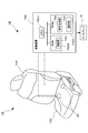
- FIG. 1 It is a figure which shows the whole structure of the vehicle seat which concerns on embodiment.
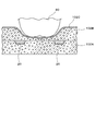
- A) is sectional drawing which shows the state of the sensor in a away state
- (b) is sectional drawing which shows the state of the sensor in a seating state. It is sectional drawing which shows arrangement
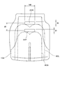
- FIG. 1 It is a top view which shows the shape and arrangement
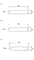
- (A) is a figure which shows the rectangular detection surface in a sensor
- (b) is a figure which shows the chamfered rectangular detection surface in a sensor
- (c) is a figure which shows the elliptical detection surface in a sensor It is. It is a figure which shows a sensor group. It is a top view which shows the shape and arrangement
- the vehicle seat 10 includes a seat cushion 102 that is a part where the seated person 80 sits, and a part that is pivotally attached to the rear part of the seat cushion 102 and leans against the seated person 80. And a respiration measurement device 12 having a sensor 20 (described later) provided in the seat cushion 102.
- the seat cushion 102 includes a urethane pad 102A, a urethane slab 102B bonded to the upper surface thereof, and a skin 102C provided to cover the urethane slab 102B.
- the respiration measurement device 12 includes a sensor 20 provided in the vicinity of the upper surface of the seat cushion 102, and an arithmetic device 70C that generates a waveform related to respiration based on a signal obtained from the sensor 20.
- the sensor 20 is a resistance pressure-sensitive sensor having a circular detection surface having a diameter of about 8 mm and a thickness of 1 mm.
- the sensor 20 includes a lower film sheet 200 having an electrode 206 attached to the upper surface, an upper film sheet 202 having flexibility having an electrode 208 attached to the lower surface, and a lower film.
- the sheet 200 and the upper film sheet 202 are configured by a spacer 204 provided so as to be separated at a predetermined interval.
- the electrodes 206 and 208 are made of, for example, a combination of silver, carbon, pressure sensitive ink, and the like.
- the upper film sheet 202 is deformed downward in accordance with the magnitude of pressure applied from the upper surface, so that the electrode 208 and the electrode 206 are close to the lower film sheet 200. Will come into contact. If the contact resistance generated between the electrode 206 and the electrode 208 increases after the contact, the electrical resistance value between the electrodes decreases.
- the sensor 20 transmits an electrical signal related to the electrical resistance value to a computing device 70C, which will be described later.
- the computing device 70C calculates a pressure based on the electrical signal related to the electrical resistance value, and breathes based on the computed pressure. The signal will be measured.
- the senor 20 is disposed between the urethane pad 102A and the urethane slab 102B.
- the senor 20 has a rear edge (vehicle described below as a seated person contact surface) in which the buttocks of the seated person 80 and the skin 102C of the seat cushion 102 are in contact in plan view. 2 are provided so as to follow the forward direction of the forward direction and the reverse direction of the forward direction.
- the two sensors 20 are arranged such that the center distance in the width direction of the seat cushion 102 is about 260 mm.
- the sensor 20 is provided within a range of about 100 to 140 mm behind the center of the maximum load area LA where the maximum load is applied from the buttocks of the seated person 80 in the seat cushion 102.
- the maximum load area LA is an area determined based on a dummy conforming to the SAE standard.
- the sensor 20 arranged at the front end in the arrangement range is indicated by a broken line as a virtual line. Unless otherwise noted, the sensor 20 is indicated by a solid line in each drawing to clarify the distinction from other lines.
- the arithmetic unit 70C includes a CPU (Central Control Unit) for arithmetic control. Processing unit (70CA), RAM (Random Access Memory) 70CB, and ROM (Read Only Memory) 70CC.
- the arithmetic device 70C receives an electrical signal related to the resistance value of the sensor 20 and outputs a respiratory signal. It should be noted that a signal other than the respiratory signal is removed from the pressure signal by the filter, specifically, the vibration of the vehicle, the brake of the seated person 80, the pressure change due to the accelerator operation, and other noises are removed, and only the respiratory signal is amplified. The respiratory signal is extracted.
- control of extraction of a respiration signal based on a pressure signal from the sensor 20 in the respiration measurement device 12 and calculation of the respiration rate from the respiration signal is an essential configuration of the present invention. Since it is not a main configuration for solving the problem, a specific description is omitted.
- the RAM 70CB temporarily stores parameters including signals under calculation control and input / output signals, and functions as a storage unit 700 that stores pressure signals and other signals converted into digital signals.
- the ROM 70CC stores a program executed by the CPU 70CA and a parameter having a predetermined value.
- a waveform generation unit 702 that generates pressure waveform data from an electrical signal related to a resistance value obtained from the sensor 20, and a selection unit 704 that selects pressure waveform data corresponding to respiration are recorded as programs. .
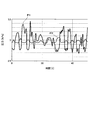
- the waveform generation unit 702 generates pressure waveform data P1 and P2 (see FIG. 5) with the pressure on the vertical axis and the time on the horizontal axis based on the electrical signal related to the resistance value of the sensor 20 stored in the storage unit 700, respectively. It has a function to generate.
- the selection unit 704 has a function of selecting pressure waveform data indicating a fluctuating pressure of a predetermined value or more in synchronization with respiration from the pressure waveform data P1 and P2, and setting it as respiration signal data. For example, as this selection criterion, when the selection unit 704 selects one of the pressure waveform data P1 and P2 shown in FIG. 5, the fluctuation pressure of about ⁇ 0.1 kPa is approximately equal to the respiration cycle. Pressure waveform data P1 that appears periodically at intervals of 3 to 4 seconds is selected.
- the selection unit 704 is configured to select a pressure signal that is synchronized with respiration, so that a respiration signal that is long in time, such as lacking, and has an extremely large pressure change is regarded as noise and excluded as a determination target. Has been.
- the senor 20 is disposed along the rear edge of the seated person contact surface in a plan view. Further, since the sensor 20 is disposed between the urethane pad 102A and the urethane slab 102B, a load from the seated person 80 is applied to the sensor 20 via the skin 102C and the urethane slab 102B. .
- the sensor 20 Since the sensor 20 is not disposed directly under the buttocks but is disposed along the edge of the seated person contact surface, a large pressure is not applied, and a minute pressure fluctuation accompanying breathing can be detected. In addition, since the sensor 20 is not arranged immediately below the buttock, the sensor 20 is not required to have high pressure resistance. As a result, the sensor 20 cannot detect bending deformation with respect to the pressure detection surface, and can provide high accuracy with respect to the detection of the respiratory signal even if the sensor 20 is inexpensive and detects only the pressure in the vertical direction. Moreover, the load of the pressure applied to the sensor 20 is reduced by the arrangement, whereby the sensor 20 can be provided with a long life.
- the respiration measuring device 12 may be connected to the display D to display the breathing state of the seated person. In this way, it is possible to visually monitor the breathing state of the seated person 80, and thus the consciousness state.
- the seated person 80 and other occupants may sound an alarm to be perceived by hearing.
- the seated person 80 and other occupants may drive the vibration motor to sense it by tactile sense, or may cause the irradiation device such as LED to blink and sense it visually.
- the senor 20 having the circular detection surface is described as being provided along the edge of the seating contact surface of the seated person 80.
- the present invention is not limited to the sensor having a circular sensor pressure detection surface as long as the sensor is arranged along the edge of the seated person contact surface.
- the sensors 22, 24, and 26 according to the first modification will be described.
- description of the contents overlapping with the vehicle seat 10 according to the embodiment is omitted.
- the senor 22 has a rectangular pressure detection surface composed of a short side of about 20 mm and a long side of about 180 mm, and the long side is a seating person contact surface. It is arranged along the rear edge.
- each pressure detection surface of the sensor 24 has a rectangular shape having a short side of about 20 mm and a long side of about 100 mm, and the long side runs along the trailing edge of the seated person contact surface.
- the pair of sensors 24 are arranged with an angle of 130 ⁇ 5 ° in front of the central axis extending in the front-rear direction of the seat cushion 102 and at an interval of about 100 mm. Yes.
- a pair of sensors 24 are arranged in a direction that spreads forward in plan view, so that when the buttocks move in the front-rear direction in accordance with a change in the posture of the seated person 80, the sensors 24 are long in the width direction of the seat cushion 102.
- the angle portion is less likely to move away from the detection surface by the angle. That is, it becomes possible to acquire a more accurate and accurate breathing signal.
- the senor 26 has a curved arc-shaped pressure detection surface having a width of about 20 mm and a radius of curvature of about 300 mm, and the rear edge of the seated person contact surface in a plan view. It is arrange
- the sensors 22, 24, and 26 are arranged so as to be within a range of about 100 to 140 mm rearward with respect to the center of the maximum load area LA as in the case of the sensor 20.
- the sensors 22, 24, and 26 are arranged so that the longitudinal direction is along the edge of the seated person contact surface in plan view. For this reason, since the detection surface along the edge part of a seated person contact surface becomes wide, even if a seated person's attitude
- the senor 22 and the sensor 26 may be configured by a set of a plurality of sensors.
- the pressure signal detected by the arithmetic unit 70C is detected.
- the selection unit 704 is unnecessary.
- the arithmetic device 70C can acquire a stable respiration signal by selecting a pressure signal waveform synchronized with the respiration from the waveforms of the pressure signals detected by the two sensors.
- Sensors 22R and 22F, sensors 32R and 32F, sensors 42R and 42F, sensors 26R and 26F, sensors 24R and 24F, and sensors 28R and 28F according to a second modified example described below are large seated persons 80L having physical differences.
- the seat cushion 102 is arranged in the front-rear direction as a main feature.
- the small seated person 80S is, for example, a person of about 150 cm in which the cumulative number from the shorter height in adult Japanese women is 5% of the total number.
- the large seated person 80L is, for example, a person of about 190 cm in which the cumulative number of adult American men from the shortest is 95% of the total number.
- the sensor 22R has the same shape as the sensor 22 and is disposed at the same position.
- the sensor 22F has the same shape as the sensor 22 and the sensor 22R, and is disposed at the same position as the sensor 22 and the sensor 22R in the width direction of the seat cushion 102, and from the sensor 22R in the front-rear direction. Are arranged at a distance of about 85 mm.
- the sensor 22F arranged in this way is along the edge of the seated person contact surface of the seated person 80S in plan view. Therefore, by arranging the sensors 22R and 22F in this way, it is possible to suitably acquire a respiratory signal not only for the large seated person 80L but also for the small seated person 80S.
- the width WR of the rear sensor 32R is formed wider than the width WF of the front sensor 32F.
- the width WR is about 240 mm
- the width WF is about 120 mm.
- the widths of the sensors 32R and 32F are allocated, so that the edges of the seated person contact surfaces of the small seated person 80S and the large seated person 80L are in a similar range. That is, when it is assumed that both the large seated person 80L and the small seated person 80S are seated, it is more preferable to adopt such a configuration.
- the center part in the width direction of the sensors 32R and 32F in other words, the center part in the width direction of the seat cushion 102 is located away from the edge of the seated person contact surface. For this reason, about the center part of the width direction of the sensors 32R and 32F, functional importance is low. Therefore, for example, the sensor 32R, 32F is divided and arranged without arranging the sensor at the center in the width direction of the seat cushion 102, and the width as in the sensors 42R, 42F shown in FIG. Two each may be arranged in the direction.
- two sensors 42R are arranged at a center of the width direction at a distance of about 100 mm so as to follow the rear edge of the seated person contact surface of the seated person 80L in plan view. Further, the two sensors 42R are arranged so that the outer interval in the width direction is about 300 mm. Further, the sensor 42F is arranged at a distance of about 85 mm forward from the sensor 42R in the front-rear direction, and is about 60 mm in the center in the width direction so as to follow the rear edge of the seated person contact surface of the seated person 80S. Two are arranged at intervals. Further, the two sensors 42F are arranged so that the outer interval in the width direction is about 240 mm. The sensor 42R is disposed on the outer side in the width direction than the sensor 42F. For this reason, the suitable pressure signal corresponding to a respiration signal can be acquired more stably irrespective of the physique difference of the seated person 80.
- the sensors 26R and 26F having the arc-shaped pressure detection surface may be arranged in the same range and the interval in the front-rear direction as in the above example.
- the sensor 26R has an arc-shaped pressure detection surface having a width of about 20 mm and a radius of curvature of about 340 mm.
- the sensor 26F has an arc-shaped pressure detection surface having a width of about 20 mm and a radius of curvature of about 260 mm.
- the dimension in the width direction of the sensor 26R is about 340 mm, and the dimension in the width direction of the sensor 26F is about 260 mm. That is, the sensor 26R is disposed on the outer side in the width direction than the sensor 26F. For this reason, the suitable pressure signal corresponding to a respiration signal can be acquired more stably irrespective of the physique difference of the seated person 80.
- each of the pressure detection surfaces of the sensors 24R and 24F has a rectangular shape having a short side of about 20 mm and a long side of about 100 mm.
- the two sensors 24R are arranged such that the outer distance in the width direction is about 380 mm, and the distance of about 100 mm is left at the center in the width direction.
- the two sensors 24F have an outer interval of about 340 mm in the width direction, form an angle of 130 ⁇ 5 ° in front of the central axis extending in the front-rear direction of the seat cushion 102, and about the center in the width direction. It arrange
- the sensor 24R is disposed on the outer side in the width direction than the sensor 24F, a suitable pressure signal corresponding to the breathing signal can be acquired more stably regardless of the physique difference of the seated person 80.
- the front row side sensor 24F is disposed so as to have an angle of 130 ⁇ 5 ° or less, which is the angle of the rear row side sensor 24R, along the buttocks of the small seated person 80S.
- the sensor 24R is disposed so as to intersect the center line C1 extending in the front-rear direction in the maximum load area LA1 of the seated person 80L in plan view.
- the sensor 24F is preferably arranged so as to intersect with the center line C1 extending in the front-rear direction in the maximum load region LA2 of the seated person 80S in plan view. .
- a pair of rear sensors 28R arranged in a direction spreading toward the rear in plan view and a distance of about 85 mm in front of the sensor 28R, and a pair in a direction spreading toward the rear in plan view. It may consist of the sensor 28F arranged.
- Each of the pair of sensors 28R and the pair of sensors 28F is arranged to form an angle of about 130 ⁇ 5 ° on the rear side.
- Each of the sensors 28R and 28F includes two pressure detection surfaces each having a rectangular shape having a short side of about 20 mm and a long side of about 100 mm.
- Each of the sensors 28R and 28F is disposed so that the longitudinal direction is along the rear edge of the seated person contact surface with an interval of about 10 mm in the width direction, and the same range and distance as in the above example. It is.
- the sensors 42S and 42L have a rectangular detection surface composed of a short side of about 20 mm and a long side of about 100 mm.
- the sensors 42S and 42L are disposed on the seat cushion 102 so that the longitudinal direction is directed in the front-rear direction.
- the two sensors 42S are arranged so that the outer interval in the width direction is about 320 mm.
- the two sensors 42L are arranged so that the outer interval in the width direction is about 380 mm.
- the detection surface of the sensor in the above has been described as a rectangular or arc-shaped surface, it may be a surface having a long and short surface, for example, the detection surface of the sensor 24 is shown in FIG.
- the detection surface 220 is not limited to the rectangular detection surface 220, and may be a chamfered rectangular detection surface 222 as shown in FIG. 17B, or an elliptical detection surface as shown in FIG. It may be surface 224.
- the sensor described as having a rectangular detection surface may be a sensor group 300 including sensors 302 having a plurality of circular detection surfaces as shown in FIG.
- the pressure signal corresponding to the respiratory signal can be selected from the plurality of sensors 302, and the respiratory signal can be acquired more stably.
- a plurality of sensors 30R having a circular detection surface are arranged so as to be curved along the rear edge of the seated person contact surface of the seated person 80L.
- a plurality of sensors 30 ⁇ / b> F having a surface may be arranged so as to be curved along the rear edge of the seated person contact surface of the seated person 80 ⁇ / b> S.
- the senor is arranged along the edge of the seated person contact surface, and the type is not limited to the resistance pressure type sensor described above, and a sensor such as a strain gauge may be used.
- a 150 cm person is assumed as an assumed small seated person and a 190 cm person is assumed as an assumed large seated person, but this assumption is arbitrary.
- the physique corresponding to the assumption is used as a reference.
- a breathing signal of a seated person can be detected with high accuracy by arranging a pressure sensor along the edge of the seated person contact surface.
- vehicle seat according to the present invention is not limited to an automobile seat, and includes on-land motorcycles, scooters, snowmobiles, water bikes, and three-wheel buggy cars, straddle-type vehicles, or construction equipment seats. Vehicle seats, etc. shall be included.
Landscapes
- Health & Medical Sciences (AREA)
- Life Sciences & Earth Sciences (AREA)
- Engineering & Computer Science (AREA)
- General Health & Medical Sciences (AREA)
- Heart & Thoracic Surgery (AREA)
- Surgery (AREA)
- Biophysics (AREA)
- Pathology (AREA)
- Medical Informatics (AREA)
- Molecular Biology (AREA)
- Physics & Mathematics (AREA)
- Animal Behavior & Ethology (AREA)
- Biomedical Technology (AREA)
- Public Health (AREA)
- Veterinary Medicine (AREA)
- Physiology (AREA)
- Psychiatry (AREA)
- Aviation & Aerospace Engineering (AREA)
- Transportation (AREA)
- Mechanical Engineering (AREA)
- Pulmonology (AREA)
- Developmental Disabilities (AREA)
- Social Psychology (AREA)
- Dentistry (AREA)
- Oral & Maxillofacial Surgery (AREA)
- Psychology (AREA)
- Child & Adolescent Psychology (AREA)
- Hospice & Palliative Care (AREA)
- Educational Technology (AREA)
- Artificial Intelligence (AREA)
- Computer Vision & Pattern Recognition (AREA)
- Signal Processing (AREA)
- Cardiology (AREA)
- Seats For Vehicles (AREA)
- Measurement Of The Respiration, Hearing Ability, Form, And Blood Characteristics Of Living Organisms (AREA)
- Chair Legs, Seat Parts, And Backrests (AREA)
- Measuring And Recording Apparatus For Diagnosis (AREA)
Abstract
着座者の呼吸信号を高い精度で検出する。車両用シートは、シートクッション(102)と、着座者(80)から加わる荷重から圧力信号を検出するセンサ(20)とを備える。センサ(20)は、シートクッション(102)と着座者(80)の臀部との接触部の縁に沿うように配設されている。センサ(20)は、検出した圧力信号を、着座者(80)の演算装置に送信する。呼吸計測装置は、センサ(20)によって検出された圧力信号を演算装置によって前記着座者(80)の呼吸信号に演算する。
Description
本発明は、車両用シートに係り、呼吸を計測可能な車両用シートに関する。
安全な車両走行には、運転者の健康状態が密接に関係する。このため、例えば特許文献1は、運転者の呼吸等の身体情報を検出する装置を車両用シートに設けることで、運転者の体調を監視する技術を開示している。
具体的には、特許文献1は、シートクッションに配置された着座者の荷重の変化を検出するセンサと、センサによって得られた荷重の変化に基づいて生体情報を演算する演算部とを備える生体情報検出装置を開示している。このセンサは、長さ方向又は曲げ方向の変形を検出する長尺状の圧電フィルムから成る。このセンサは、予め前後方向が定められているシートクッションに対し、着座者の臀部に対向する位置に亘ってシートクッションの後方から前方への方向と長尺方向とが一致するように配設される。この生体情報検出装置は、センサによって着座者から加わる荷重の変化を検出し、検出された信号に基づいて演算部が演算することによって呼吸や心拍を検出するというものである。
着座者の臀部直下において呼吸に応じた圧力変化を検出するためには、特許文献1に開示されたセンサのように、曲げ変形を検出可能なセンサを用いる必要があった。また、一般的に、センサにおける耐荷重性能と検出精度とは相反する特性となる。このため、着座者の臀部直下においては、検出面に対して垂直な荷重のみを検出する荷重センサでは、精度の高い呼吸信号の計測ができなかった。
本発明はかかる問題点に鑑みてなされたものであり、センサの適用範囲を広くでき、着座者の呼吸信号を高い精度で検出できる車両用シートを提供することを目的とする。
前記課題は、本発明の車両用シートによれば、シートクッションと、前記シートクッションに設けられ、着座者から加わる荷重から圧力信号を検出する少なくとも1つのセンサと、検出された前記圧力信号を前記着座者の呼吸信号に演算する演算装置と、を有して前記着座者の呼吸を計測する計測装置と、を車両用シートが備え、前記センサは、前記シートクッションと前記着座者の臀部との接触部の縁に沿うように配設され、検出した圧力信号を前記演算装置に送信すること、により解決される。
このように、センサが、シートクッションと着座者の臀部との接触部の縁に沿うようにシートクッションに配設されていることで、センサの適用範囲を広くでき、精度の高い計測が可能となる。
また、前記センサは、縦横の長さが異なる検出面を有し、前記縁に長尺方向が沿うように配設されていると好適である。
このようにすると、シートクッションと着座者の臀部との接触部の縁に沿う位置にあるセンサの検出面の範囲を広くでき、精度が高く安定した計測が可能となる。
このようにすると、シートクッションと着座者の臀部との接触部の縁に沿う位置にあるセンサの検出面の範囲を広くでき、精度が高く安定した計測が可能となる。
また、前記センサは、車両の進行方向を前方向とした場合に、前記縁における後側に設けられていると好適である。
このようにすると、大きな荷重負荷が着座者の臀部からセンサに加わる蓋然性を低減することができる。
このようにすると、大きな荷重負荷が着座者の臀部からセンサに加わる蓋然性を低減することができる。
また、前記センサは、車両の進行方向を前方向とした場合に、前後に少なくとも2つ配設されていると好適である。
このようにすると、着座者の体格差によらず、精度が高く安定した計測が可能となる。
このようにすると、着座者の体格差によらず、精度が高く安定した計測が可能となる。
また、前記センサは、車両の進行方向を前方向とした場合に、前後方向のいずれか一方に広がる向きで少なくとも一対配置されていると好適である。
このようにすると、シートクッションと着座者の臀部との接触部の縁に沿う位置にあるセンサの検出面の範囲を広くでき、精度が高く安定した計測が可能となる。
このようにすると、シートクッションと着座者の臀部との接触部の縁に沿う位置にあるセンサの検出面の範囲を広くでき、精度が高く安定した計測が可能となる。
また、前記センサは、湾曲した形状に形成されているようにしてもよい。
このようにすると、シートクッションと着座者の臀部との接触部の縁に沿う位置にあるセンサの検出面の範囲を広くでき、精度が高く安定した計測が可能となる。
このようにすると、シートクッションと着座者の臀部との接触部の縁に沿う位置にあるセンサの検出面の範囲を広くでき、精度が高く安定した計測が可能となる。
また、前記センサは、前記着座者が着座している状態で、前記臀部から前記シートクッションに最大荷重が付加される領域よりも後方に少なくとも一部が位置するように設けられていると好適である。
このようにすると、最大荷重が付加される領域よりも後方に設けることで、より精度の高い検出が可能となる。
このようにすると、最大荷重が付加される領域よりも後方に設けることで、より精度の高い検出が可能となる。
また、前記センサは、後側に設けられた第1センサと、前側に設けられた第2センサとを含み、前記第1センサは、前記第2センサよりもシート幅方向外側に配置されていると好適である。
このようにすると、着座者の体格差によらずに呼吸信号に対応する好適な圧力信号をより安定して取得できる。
このようにすると、着座者の体格差によらずに呼吸信号に対応する好適な圧力信号をより安定して取得できる。
更に、前記センサは複数設けられ、前記計測装置は、前記複数のセンサから検出されたデータのうち、呼吸を反映するデータを選択して計測するようにすると好ましい。
このようにすると、呼吸を安定して計測することが可能となる。
このようにすると、呼吸を安定して計測することが可能となる。
本発明によれば、センサが、シートクッションと着座者の臀部との接触部の縁に沿うようにシートクッションに配設されていることで、センサの適用範囲を広くでき、精度の高い計測が可能となる。
また、本発明によれば、シートクッションと着座者の臀部との接触部の縁に沿う位置にあるセンサの検出面の範囲を広くでき、精度が高く安定した計測が可能となる。
また、本発明によれば、着座者の臀部から大きな荷重負荷がセンサに加わる蓋然性を低減することができる。
また、本発明によれば、着座者の体格差によらず、精度が高く安定した計測が可能となる。
また、本発明によれば、シートクッションと着座者の臀部との接触部の縁に沿う位置にあるセンサの検出面の範囲を広くでき、精度が高く安定した計測が可能となる。
また、本発明によれば、シートクッションと着座者の臀部との接触部の縁に沿う位置にあるセンサの検出面の範囲を広くでき、精度が高く安定した計測が可能となる。
また、本発明によれば、最大荷重が付加される領域よりも後方に設けることで、より精度の高い検出が可能となる。
また、本発明によれば、着座者の体格差によらずに呼吸信号に対応する好適な圧力信号をより安定して取得できる。
また、本発明によれば、呼吸を安定して計測することが可能となる。
以下、本発明に係る車両用シートの実施形態について、添付の図面を参照して具体的に説明する。
本実施形態に係る車両用シート10は、図1に示すように、着座者80が座る部位であるシートクッション102と、シートクッション102の後部に回動可能に取り付けられ着座者80がもたれかかる部位であるシートバック104と、シートクッション102内に設けられた後述するセンサ20を有する呼吸計測装置12と、を備える。
シートクッション102は、図3に示すように、ウレタンパッド102Aと、その上面に接着されたウレタンスラブ102Bと、更にその上を覆うように設けられた表皮102Cとを備える。
呼吸計測装置12は、シートクッション102の上面近傍に設けられたセンサ20と、センサ20から得られる信号に基づいて、呼吸に係る波形を生成する演算装置70Cと、を備える。
センサ20は、直径約8mm、厚さが役1mmである円形の検出面を有する抵抗感圧式のセンサである。センサ20は、図2(a)に示すように、上面に電極206が貼着された下フィルムシート200と、下面に電極208が貼着され可撓性を有する上フィルムシート202と、下フィルムシート200と上フィルムシート202とが所定の間隔で離間するよう設けられたスペーサ204と、から構成される。電極206,208は、例えば、銀、カーボン、感圧インク等の組み合わせから成る。
このように構成されるセンサ20においては、上フィルムシート202が、上面から加えられる圧力の大きさに応じて下方に変形することで、下フィルムシート200に近接し、電極208と電極206とが接触することになる。接触後、電極206と電極208との間に生じる接触抵抗が大きくなると、電極間の電気抵抗値が小さくなる。センサ20は、この電気抵抗値に係る電気信号が後述する演算装置70Cに送信され、演算装置70Cによって、電気抵抗値に係る電気信号に基づいて圧力が演算され、演算された圧力に基づいて呼吸信号が計測されることとなる。
また、センサ20は、図3に示すように、ウレタンパッド102Aとウレタンスラブ102Bとの間に配置されている。
また、センサ20は、図4に示すように、平面視においては、着座者80の臀部とシートクッション102の表皮102Cとが接触する面(以下において着座者接触面と記載)の後縁(車両の前進方向を前方向、その逆方向を後ろ方向として説明する。)に沿うように2つ設けられている。具体的な配置としては、2つのセンサ20は、シートクッション102の幅方向における中心間隔が約260mmとなるように配置されている。また、センサ20は、シートクッション102における、着座者80の臀部から最大荷重が付加される最大荷重領域LAの中心から後方約100~140mmの範囲内に設けられている。この最大荷重領域LAは、SAE規格に準拠したダミーに基づいて定められる領域である。このセンサ20の配設範囲を明示するために、図4では、配設範囲内における前端に配置されたセンサ20を仮想線としての破線で示す。なお、このような言及がない限り、センサ20は、他の線との区別を明確にするため各図において実線で示される。
演算装置70Cは、図1に示すように、演算制御用のCPU(Central
Processing Unit)70CAと、RAM(Random Access Memory)70CBと、ROM(Read Only Memory)70CCと、を備える。演算装置70Cには、センサ20の抵抗値に係る電気信号が入力され、呼吸信号が出力される。なお、圧力信号からフィルタによって呼吸信号以外の信号、具体的には、車両の振動や着座者80のブレーキ、アクセル操作による圧力変化、その他のノイズは除去され、更に呼吸信号のみが増幅されることで、呼吸信号が抽出される。なお、本実施形態では、呼吸計測装置12におけるセンサ20からの圧力信号に基づく呼吸信号の抽出、呼吸信号からの呼吸数の算出等の制御については、本発明に必須の構成ではあるが、課題解決のための主要な構成ではないので具体的な説明を省略する。
Processing Unit)70CAと、RAM(Random Access Memory)70CBと、ROM(Read Only Memory)70CCと、を備える。演算装置70Cには、センサ20の抵抗値に係る電気信号が入力され、呼吸信号が出力される。なお、圧力信号からフィルタによって呼吸信号以外の信号、具体的には、車両の振動や着座者80のブレーキ、アクセル操作による圧力変化、その他のノイズは除去され、更に呼吸信号のみが増幅されることで、呼吸信号が抽出される。なお、本実施形態では、呼吸計測装置12におけるセンサ20からの圧力信号に基づく呼吸信号の抽出、呼吸信号からの呼吸数の算出等の制御については、本発明に必須の構成ではあるが、課題解決のための主要な構成ではないので具体的な説明を省略する。
RAM70CBは、演算制御中の信号及び入出力される信号を含むパラメータを一時記憶するもので、デジタル信号に変換された圧力信号その他の信号を格納する格納部700として機能を有する。
ROM70CCは、CPU70CAが実行するプログラム及び所定値のパラメータを記憶するものである。ROM70CCには、センサ20から得られた抵抗値に係る電気信号から圧力波形データを生成する波形生成部702と、呼吸に対応する圧力波形データを選択する選択部704とがプログラムとして記録されている。
波形生成部702は、格納部700に格納されたセンサ20の抵抗値に係る電気信号を基に、圧力を縦軸、時間を横軸とする圧力波形データP1,P2(図5参照)をそれぞれ生成する機能を有する。
選択部704は、圧力波形データP1,P2から呼吸に同期し、所定以上の変動圧力が示された圧力波形データを選択し、呼吸信号データとして設定する機能を有する。例えば、この選択基準としては、選択部704は、図5に示された圧力波形データP1,P2のいずれかを選択する場合、約±0.1kPaの変動圧力が、呼吸の周期とほぼ等しい約3~4秒間隔で周期的に現れる圧力波形データP1を選択する。なお、選択部704は、呼吸に同期する圧力波形データの選択においては、欠伸のような時間的に長く、極端に大きな圧力変化を有する呼吸信号をノイズとみなし、判定対象として除外するように設定されている。
上記の実施形態に係る車両用シート10は、平面視において、着座者接触面の後縁に沿うようにセンサ20が配置されている。また、センサ20は、ウレタンパッド102Aとウレタンスラブ102Bとの間に配置されているために、着座者80からの荷重は、表皮102Cとウレタンスラブ102Bを介してセンサ20に付加されることとなる。
センサ20は、臀部直下に配設されずに着座者接触面の縁に沿って配置されているため、大きな圧力がかからず、呼吸に伴う微小な圧力変動を検出することが可能となる。また、センサ20は臀部直下に配置されるものではないため、センサ20に、高い耐圧性能は要求されない。結果として、センサ20は、圧力検出面に対して曲げ変形を検出できず、垂直方向の圧力のみを検出する安価なものであっても、呼吸信号検出に関して高い精度を備えることができる。また、センサ20に加わる圧力の負荷が、その配置によって低減されることで、センサ20に高寿命性を備えさせることができる。
なお、呼吸計測装置12は、図1に示すように、ディスプレイDに接続されて、着座者の呼吸状態を表示するようにしてもよい。このようにすれば、着座者80の呼吸状態、延いては意識状態をビジュアルによって監視することが可能となる。その他、例えば、計測された呼吸信号において覚醒度低下、過呼吸等異常が検出した場合に、着座者80及び他の乗員に、アラームを鳴動させて聴覚で感知させるようにしてもよい。また、着座者80及び他の乗員に、振動モータを駆動させて触覚で感知させるようにしてもよく、LED等の照射装置を点滅させて視覚で感知させるようにしてもよい。
(第1変形例)
上記の実施形態に係る車両用シート10においては、円形の検出面を有するセンサ20が、着座者80の着座接触面の縁に沿って設けられているとして説明した。しかし、本発明は、着座者接触面の縁に沿ってセンサが配置されていればよく、センサの圧力検出面の形状が円形であることに限定されない。次に、第1変形例に係るセンサ22,24,26について説明する。なお、以下において、特徴の差異を明確にするため、上記実施形態に係る車両用シート10と重複する内容については説明を省略する。
上記の実施形態に係る車両用シート10においては、円形の検出面を有するセンサ20が、着座者80の着座接触面の縁に沿って設けられているとして説明した。しかし、本発明は、着座者接触面の縁に沿ってセンサが配置されていればよく、センサの圧力検出面の形状が円形であることに限定されない。次に、第1変形例に係るセンサ22,24,26について説明する。なお、以下において、特徴の差異を明確にするため、上記実施形態に係る車両用シート10と重複する内容については説明を省略する。
例えば、図6に示すように、センサ22は、約20mmの短尺の辺と約180mmの長尺の辺とからなる長方形状の圧力検出面を有し、長尺の辺が着座者接触面の後縁に沿うように配置されている。
また、図7に示すように、センサ24は、平面視において前方にかけて広がる向きで一対配置されている。具体的には、センサ24のそれぞれの圧力検出面は約20mmの短尺の辺と約100mmの長尺の辺とからなる長方形状であり、着座者接触面の後縁に長尺の辺が沿うように配置されている。一対のセンサ24は、具体的には、両者がシートクッション102の前後方向に延出する中心軸を対称に前側に130±5°の角度を成し、約100mmの間隔を空けて配置されている。
センサ24は、平面視において前方にかけて広がる向きで一対配置されていることで、着座者80の姿勢の変化に応じて臀部が前後方向に移動する場合に、シートクッション102の幅方向に長尺の辺が配置されているセンサ22と比較して、その角度分、検出面から臀部が遠ざかりにくくなる。つまり、より安定して精度の高い呼吸信号を取得可能となる。
また、図8に示すように、センサ26は、約20mmの幅を有し約300mmの曲率半径を有する湾曲した円弧状の圧力検出面を有し、平面視において、着座者接触面の後縁に長尺方向が沿うように配置されている。
なお、センサ22,24,26は、センサ20と同様、最大荷重領域LAの中心を基準として後方に約100~140mmの範囲内に収まるように配置されている。
また、センサ22,24,26は、平面視において、長尺方向が着座者接触面の縁に沿うように配置されている。このため、着座者接触面の縁部に沿う検出面が広くなるため、着座者の姿勢の変化によっても、センサ22,24,26が無負荷状態になることが抑制される。つまり、呼吸に同期する良好な圧力信号を検出できる蓋然性が高くなることで、圧力信号を安定して取得可能となる。
なお、後述するが、センサ22及びセンサ26は、複数のセンサの集合から構成されるものであってもよく、また、1つのセンサから成る場合には、演算装置70Cにおいて、検出された圧力信号を選択する機能を当然要さず、選択部704は不要である。
また、例えば、着座者80が足を組んだ状態等、シートクッション102の幅方向において着座者80との接触に偏りが生じる場合がある。この場合に、一つのセンサから成る場合には取得される圧力信号が小さくなることがある。このような場合に、前後方向において同じ位置に2以上設けられたセンサ20,24であれば、幅方向における接触の偏りによる圧力信号の取得についての影響を回避することができる。具体的な処理としては、演算装置70Cが、2つのセンサから検出された圧力信号の波形から、上記の呼吸に同期する圧力信号の波形を選択することで、安定した呼吸信号を取得できる。
(第2変形例)
次に説明する第2変形例に係るセンサ22R,22F、センサ32R,32F、センサ42R,42F、センサ26R,26F、センサ24R,24F、センサ28R,28Fは、体格差のある大柄な着座者80L及び小柄な着座者80Sを考慮して、シートクッション102において前後方向に配置されていることを主な特徴として備えるものである。ここで、小柄な着座者80Sは、例えば、成人の日本人女性において身長の低い方からの累計数が全体数に対して5%となる約150cmの人である。また、大柄な着座者80Lは、例えば、成人の米国人男性において身長の低い方からの累計数が全体数に対して95%となる約190cmの人である。
次に説明する第2変形例に係るセンサ22R,22F、センサ32R,32F、センサ42R,42F、センサ26R,26F、センサ24R,24F、センサ28R,28Fは、体格差のある大柄な着座者80L及び小柄な着座者80Sを考慮して、シートクッション102において前後方向に配置されていることを主な特徴として備えるものである。ここで、小柄な着座者80Sは、例えば、成人の日本人女性において身長の低い方からの累計数が全体数に対して5%となる約150cmの人である。また、大柄な着座者80Lは、例えば、成人の米国人男性において身長の低い方からの累計数が全体数に対して95%となる約190cmの人である。
図9に示すように、センサ22Rは、センサ22と同じ形状であり同じ位置に配置されている。これに対して、センサ22Fは、センサ22及びセンサ22Rと同じ形状であり、シートクッション102の幅方向においては、センサ22及びセンサ22Rと等しい位置に配置され、前後方向においては、センサ22Rから前側に約85mmの距離を空けて配置されている。
このように配置されたセンサ22Fは、平面視において、着座者80Sの着座者接触面の縁に沿うこととなる。したがって、このようにセンサ22R,22Fが配置されていることで、大柄な着座者80Lの他、小柄な着座者80Sについても、好適に呼吸信号を取得することが可能となる。
また、このように前後方向に2列のセンサ22R,22Fが配置されていることで、例えば大柄な着座者80Lが浅く腰掛ける場合、また、小柄な着座者80Sが深く腰掛ける場合であっても安定して呼吸信号を取得することが可能となる。部品点数が増加することに伴うコスト上の問題が少ない場合には、このような構成を採用することで、大柄な着座者80Lと小柄な着座者80Sとの双方の呼吸の検出が可能となる。
また、センサ22R,22Fと同様の配置ではあるが、図10に示すように、後方のセンサ32Rの幅WRが、前方のセンサ32Fの幅WFよりも広く形成されているものであるとより好ましい。ここで、幅WRは、約240mmであり、幅WFは、約120mmである。このように、センサ32R,32Fの幅が割り当てられていることで、小柄な着座者80S及び大柄な着座者80Lのそれぞれの着座者接触面の縁に、同様の範囲で沿う構成になる。つまり、大柄な着座者80Lと小柄な着座者80Sとの双方が着座することが想定される場合には、このような構成にすることがより好ましい。
また、図10に示すように、センサ32R,32Fにおける幅方向における中央部、換言するとシートクッション102の幅方向中央部は、着座者接触面の縁から離れた位置にある。このため、センサ32R,32Fの幅方向の中央部については、機能的に重要性が低い。よって、例えば、シートクッション102の幅方向の中央部にセンサを配置せずに、センサ32R,32Fが分断されて配置されているようにして、図11に示すセンサ42R,42Fのように、幅方向に各2つずつを配置するようにしてもよい。
具体的には、センサ42Rは、平面視において、着座者80Lの着座者接触面の後縁に沿うように、幅方向における中央に約100mmの間隔を空けて2つ配設されている。また、2つのセンサ42Rは、幅方向における外側の間隔が約300mmとなるように配置されている。また、センサ42Fは、前後方向においては、センサ42Rから前側に約85mmの距離を空けて配置され、着座者80Sの着座者接触面の後縁に沿うように、幅方向における中央に約60mmの間隔を空けて2つ配置されている。また、2つのセンサ42Fは、幅方向における外側の間隔が約240mmとなるように配置されている。なお、センサ42Fよりもセンサ42Rの方が幅方向外側に配置されている。このため、着座者80の体格差によらずに呼吸信号に対応する好適な圧力信号をより安定して取得できる。
また、図12に示すように、円弧状の圧力検出面を有するセンサ26R,26Fが上記の例と同様の範囲及び前後方向の間隔で配置されているものであってもよい。具体的には、センサ26Rは、約20mmの幅を有し、曲率半径が約340mmの円弧状の圧力検出面を有する。センサ26Fは、約20mmの幅を有し、曲率半径が約260mmである円弧状の圧力検出面を有する。なお、センサ26Rの幅方向の寸法は約340mmであり、センサ26Fの幅方向の寸法は約260mmである。つまり、センサ26Fよりもセンサ26Rの方が幅方向外側に配置されている。このため、着座者80の体格差によらずに呼吸信号に対応する好適な圧力信号をより安定して取得できる。
同様に、図13に示すように、平面視において前方にかけて広がる向きで一対配置されたセンサ24Rと、センサ24Rよりも前方に、平面視において前方にかけて広がる向きで一対配置されたセンサ24Fとが、上記の例と同様の範囲及び間隔で配置されているものであってもよい。具体的には、センサ24R,24Fのそれぞれの圧力検出面は、約20mmの短尺の辺と約100mmの長尺の辺とからなる長方形状である。2つのセンサ24Rは、幅方向における外側の間隔が約380mmであり、幅方向中央において約100mmの間隔が空くように配置されている。2つのセンサ24Fは、幅方向における外側の間隔が約340mmであり、シートクッション102の前後方向に延出する中心軸を対称に前側に130±5°の角度を成し、幅方向中央において約60mmの間隔が空くように配置されている。なお、センサ24Rがセンサ24Fよりも幅方向外側に配置されているため、着座者80の体格差によらずに呼吸信号に対応する好適な圧力信号をより安定して取得できる。更に、前列側のセンサ24Fは、小柄な着座者80Sの臀部に沿うように、後列側のセンサ24Rの角度である130±5°以下の角度となるように配設されているとより好ましい。
なお、図14(a)に示すように、センサ24Rが、平面視において、着座者80Lの最大荷重領域LA1における前後方向に延出する中心線C1に交差するように配置されていると望ましい。同様に、図14(b)に示すように、センサ24Fが、平面視において、着座者80Sの最大荷重領域LA2における前後方向に延出する中心線C1に交差するように配置されていると望ましい。このように配置されていることで、着座者80S,80Lの呼吸信号に対応する圧力信号が好適に検出可能となる。
また、図15に示すように、平面視において後方にかけて広がる向きで一対配置された後方のセンサ28Rと、センサ28Rの前方に約85mmの間隔を空け、同様に平面視において後方にかけて広がる向きで一対配置されたセンサ28Fとから成るものであってもよい。一対のセンサ28Rと一対のセンサ28Fのそれぞれは、後側に約130±5°の角度を成すように配置されている。このセンサ28R,28Fは、約20mmの短尺の辺と約100mmの長尺の辺とからなる長方形状である圧力検出面を有するそれぞれ2つから構成される。センサ28R,28Fのそれぞれは、幅方向において約10mmの間隔を空け、着座者接触面の後縁に長尺方向が沿うように配置され、上記の例と同様の範囲及び間隔で配置されるものである。
(第3変形例)
上記実施形態及びその変形例においては、着座者80の着座者接触面における後縁に沿うようにセンサが設けられているものとして説明したが、本発明は、着座者接触面の縁に沿うようにセンサが設けられていればよく、このような構成に限定されない。例えば、第3変形例に係るセンサ42Sは、着座者80Sの着座者接触面の側縁に沿うように2つ、センサ42Lは、着座者80Lの着座者接触面の側縁に沿うように2つ設けられている。つまり、センサ42Sは、小柄な着座者80Sの呼吸信号を検出するために設けられており、一方センサ42Lは、大柄な着座者80Lの呼吸信号を検出するために設けられている。
上記実施形態及びその変形例においては、着座者80の着座者接触面における後縁に沿うようにセンサが設けられているものとして説明したが、本発明は、着座者接触面の縁に沿うようにセンサが設けられていればよく、このような構成に限定されない。例えば、第3変形例に係るセンサ42Sは、着座者80Sの着座者接触面の側縁に沿うように2つ、センサ42Lは、着座者80Lの着座者接触面の側縁に沿うように2つ設けられている。つまり、センサ42Sは、小柄な着座者80Sの呼吸信号を検出するために設けられており、一方センサ42Lは、大柄な着座者80Lの呼吸信号を検出するために設けられている。
具体的には、センサ42S,42Lは、約20mmの短尺の辺と約100mmの長尺の辺とからなる長方形状の検出面を有する。センサ42S,42Lは、長尺方向が前後方向に向くようにシートクッション102に配置されている。2つのセンサ42Sは、幅方向における外側の間隔が約320mmとなるように配置されている。また2つのセンサ42Lは、幅方向における外側の間隔が約380mmとなるように配置されている。このように配置されていることにより、前後方向の圧力検出範囲を広くすることができるため、着座者80に、浅く又は深く座るような姿勢の変化があったとしても安定的に呼吸信号を検出することができる。つまり、長時間の着座状態が続くことにより姿勢の変化が頻繁にある場合でも、好適に呼吸信号を検出することができる。
部品点数が増加することに伴うコスト上の問題が少ない場合には、このような構成を採用することで、大柄な着座者80Lと小柄な着座者80Sとの双方の呼吸の検出が可能となる。更に、深く腰掛ける場合と浅く腰掛ける場合との姿勢の変化に影響されずに安定して呼吸を検出できる。
また、上記におけるセンサの検出面について、長方形状又は円弧状の面として説明したが、長尺と短尺を備える面であればよく、例えば、図17(a)にセンサ24の検出面を示すように、長方形状の検出面220に限られず、図17(b)に示すように、面取りされた長方形状の検出面222であってもよく、図17(c)のように、楕円状の検出面224であってもよい。
また、上記において、長方形状の検出面を有するとして説明したセンサは、図18に示すように、複数の円形状の検出面を備えるセンサ302から構成されるセンサ群300であってもよい。このような構成であれば、複数のセンサ302のうちから、呼吸信号に対応する圧力信号を選択することができ、より安定して呼吸信号を取得することができる。
また、図19に示すように、円形状の検出面を備えるセンサ30Rが、着座者80Lの着座者接触面の後縁に沿って、湾曲するように複数配置され、同様に、円形状の検出面を備えるセンサ30Fが、着座者80Sの着座者接触面の後縁に沿って、湾曲するように複数配置される構成であってもよい。
また、センサが着座者接触面の縁に沿って配置されていればよく、その種類については、上に説明した抵抗感圧式のものに限らずストレインゲージ等のセンサでもよい。
以上、本発明を実施形態及びその変形例に基づき具体的に説明したが、本発明は上記実施形態及びその変形例に限定されるものではない。その要旨を逸脱しない範囲内で、各特徴を組み合わせる等種々の変更が可能である。例えば、センサが着座者接触面の縁に沿って配置されているならば、センサ20,22,22R,22F,24,24R,24F,26,26R,26F,28R,28F,30R,30F,32R,32F,42R,42F,42S,42L及びセンサ群300の組み合わせは任意である。
また、想定される小柄な着座者として150cmの人、また、想定される大柄な着座者として190cmの人を例に説明したが、この想定は任意である。例えば、成人の米国人のみの着座が想定される場合、又は、子供のみの着座が想定される場合等には、その想定に応じた体格を基準とするようにする。そして、基準とされた体格の者が着座した状態において、その着座者接触面の縁に沿うように圧力センサを配置することで、着座者の呼吸信号を高い精度で検出することができる。
また、本発明に係る車両用シートとは、自動車用のシートに限定されず、陸上のオートバイ、スクーター、スノーモービル、水上バイクを含み、また三輪バギー車等、跨座式乗物、又は建機シートに関する乗物用シート等を含むものとする。
また、本発明に係る車両用シートとは、自動車用のシートに限定されず、陸上のオートバイ、スクーター、スノーモービル、水上バイクを含み、また三輪バギー車等、跨座式乗物、又は建機シートに関する乗物用シート等を含むものとする。
10 車両用シート
102 シートクッション
102A ウレタンパッド
102B ウレタンスラブ
102C 表皮
104 シートバック
12 呼吸計測装置
20,22,22R,22F,24,26,28R,28F,30R,30F,42S,42L センサ
24R,26R,32R,42R センサ(第1センサ)
24F,26F,32F,42F センサ(第2センサ)
200,202 フィルムシート
204 スペーサ
206,208 電極
300 センサ群
70C 演算装置
80,80S,80L 着座者
D ディスプレイ
LA,LA1,LA2 最大荷重領域
102 シートクッション
102A ウレタンパッド
102B ウレタンスラブ
102C 表皮
104 シートバック
12 呼吸計測装置
20,22,22R,22F,24,26,28R,28F,30R,30F,42S,42L センサ
24R,26R,32R,42R センサ(第1センサ)
24F,26F,32F,42F センサ(第2センサ)
200,202 フィルムシート
204 スペーサ
206,208 電極
300 センサ群
70C 演算装置
80,80S,80L 着座者
D ディスプレイ
LA,LA1,LA2 最大荷重領域
Claims (9)
- シートクッションと、
前記シートクッションに設けられ、着座者から加わる荷重から圧力信号を検出する少なくとも1つのセンサと、検出された前記圧力信号を前記着座者の呼吸信号に演算する演算装置と、を有して前記着座者の呼吸を計測する計測装置と、を備え、
前記センサは、前記シートクッションと前記着座者の臀部との接触部の縁に沿うように配設され、検出した圧力信号を前記演算装置に送信する、
ことを特徴とする車両用シート。 - 前記センサは、縦横の長さが異なる検出面を有し、前記縁に長尺方向が沿うように配設されている、ことを特徴とする請求項1に記載の車両用シート。
- 前記センサは、車両の進行方向を前方向とした場合に、前記縁における後側に設けられている、ことを特徴とする請求項1又は2に記載の車両用シート。
- 前記センサは、車両の進行方向を前方向とした場合に、前後に少なくとも2つ配設されている、ことを特徴とする請求項1乃至3のいずれか一項に記載の車両用シート。
- 前記センサは、車両の進行方向を前方向とした場合に、前後方向のいずれか一方に広がる向きで少なくとも一対配置されていることを特徴とする請求項1乃至4のいずれか一項に記載の車両用シート。
- 前記センサは、湾曲した形状に形成されていることを特徴とする請求項1乃至5のいずれか一項に記載の車両用シート。
- 前記センサは、前記着座者が着座している状態で、前記臀部から前記シートクッションに最大荷重が付加される領域よりも後方に少なくとも一部が位置するように設けられている、ことを特徴とする請求項1乃至6のいずれか一項に記載の車両用シート。
- 前記センサは、後側に設けられた第1センサと、前側に設けられた第2センサとを含み、
前記第1センサは、前記第2センサよりもシート幅方向外側に配置されている、
ことを特徴とする請求項4に記載の車両用シート。 - 前記センサは複数設けられ、
前記計測装置は、前記複数のセンサから検出されたデータのうち、呼吸を反映するデータを選択して計測する、
ことを特徴とする請求項1乃至8のいずれか一項に記載の車両用シート。
Priority Applications (2)
| Application Number | Priority Date | Filing Date | Title |
|---|---|---|---|
| US14/395,408 US9877678B2 (en) | 2012-04-19 | 2013-04-18 | Vehicle seat |
| EP13779045.7A EP2839985A4 (en) | 2012-04-19 | 2013-04-18 | VEHICLE SEAT |
Applications Claiming Priority (2)
| Application Number | Priority Date | Filing Date | Title |
|---|---|---|---|
| JP2012095789A JP2013220810A (ja) | 2012-04-19 | 2012-04-19 | 車両用シート |
| JP2012-095789 | 2012-04-19 |
Publications (1)
| Publication Number | Publication Date |
|---|---|
| WO2013157609A1 true WO2013157609A1 (ja) | 2013-10-24 |
Family
ID=49383561
Family Applications (1)
| Application Number | Title | Priority Date | Filing Date |
|---|---|---|---|
| PCT/JP2013/061521 Ceased WO2013157609A1 (ja) | 2012-04-19 | 2013-04-18 | 車両用シート |
Country Status (4)
| Country | Link |
|---|---|
| US (1) | US9877678B2 (ja) |
| EP (1) | EP2839985A4 (ja) |
| JP (1) | JP2013220810A (ja) |
| WO (1) | WO2013157609A1 (ja) |
Families Citing this family (7)
| Publication number | Priority date | Publication date | Assignee | Title |
|---|---|---|---|---|
| JP6331890B2 (ja) * | 2014-08-29 | 2018-05-30 | 株式会社豊田中央研究所 | 乗り物用シート |
| US10486571B2 (en) | 2015-03-27 | 2019-11-26 | Ts Tech Co., Ltd. | Chair |
| JP6905198B2 (ja) * | 2015-03-27 | 2021-07-21 | テイ・エス テック株式会社 | シート |
| WO2019225124A1 (ja) * | 2018-05-24 | 2019-11-28 | 国立大学法人名古屋大学 | 生体着座検出装置 |
| JP7200813B2 (ja) * | 2019-04-15 | 2023-01-10 | トヨタ紡織株式会社 | シート |
| JP7473939B2 (ja) * | 2019-10-22 | 2024-04-24 | 株式会社デルタツーリング | 生体信号検出装置 |
| WO2023008187A1 (ja) * | 2021-07-26 | 2023-02-02 | 株式会社ブリヂストン | 推定装置、制御装置、推定方法、及び推定プログラム |
Citations (5)
| Publication number | Priority date | Publication date | Assignee | Title |
|---|---|---|---|---|
| JP2001194218A (ja) * | 1999-12-28 | 2001-07-19 | Nissan Motor Co Ltd | 乗員検知センサ |
| JP2007261310A (ja) * | 2006-03-27 | 2007-10-11 | Mazda Motor Corp | 乗員状態検出装置 |
| WO2011030491A1 (ja) * | 2009-09-09 | 2011-03-17 | パナソニック株式会社 | 車両制御装置及び車両制御方法 |
| JP2011156196A (ja) | 2010-02-02 | 2011-08-18 | Aisin Seiki Co Ltd | 生体情報検出装置 |
| WO2011114819A1 (ja) * | 2010-03-19 | 2011-09-22 | アイシン精機株式会社 | 生体情報検出装置 |
Family Cites Families (15)
| Publication number | Priority date | Publication date | Assignee | Title |
|---|---|---|---|---|
| US5853005A (en) | 1996-05-02 | 1998-12-29 | The United States Of America As Represented By The Secretary Of The Army | Acoustic monitoring system |
| JP4277073B2 (ja) * | 2003-05-21 | 2009-06-10 | 株式会社デルタツーリング | シート負荷体判定装置 |
| EP1639941A1 (en) | 2003-06-20 | 2006-03-29 | Matsushita Electric Industrial Co., Ltd. | Sleeping device and sleeper's in-bed state detection method |
| JP4502712B2 (ja) * | 2004-06-02 | 2010-07-14 | 株式会社デルタツーリング | 心身状態判定システム |
| JP4632086B2 (ja) | 2005-06-21 | 2011-02-16 | アイシン精機株式会社 | 荷重検出装置及び荷重検出方法 |
| JP4900650B2 (ja) * | 2005-11-17 | 2012-03-21 | アイシン精機株式会社 | 生体情報用圧力センサ及び生体情報用圧力検出装置 |
| DE102007056238B4 (de) * | 2006-11-29 | 2012-05-31 | Denso Corporation | Lastsensor |
| DE102008053626B4 (de) * | 2007-10-31 | 2016-09-08 | Denso Corporation | Sitz-Sensor |
| FR2943234B1 (fr) | 2009-03-18 | 2012-09-28 | Imra Europe Sas | Procede de surveillance d'un parametre biologique d'un occupant d'un siege avec reduction de bruit |
| FR2943236A1 (fr) | 2009-03-18 | 2010-09-24 | Imra Europ Sas | Procede de surveillance d'un parametre biologique d'une personne au moyen de capteurs |
| JP2011156197A (ja) | 2010-02-02 | 2011-08-18 | Aisin Seiki Co Ltd | 生体情報検出装置 |
| WO2011096144A1 (ja) | 2010-02-02 | 2011-08-11 | アイシン精機株式会社 | 生体情報検出装置 |
| US20110196243A1 (en) | 2010-02-05 | 2011-08-11 | Riheng Wu | Non-contact detection of physiological data using stochastic resonance |
| JP5573282B2 (ja) | 2010-03-26 | 2014-08-20 | アイシン精機株式会社 | 生体情報検出装置 |
| US8725311B1 (en) * | 2011-03-14 | 2014-05-13 | American Vehicular Sciences, LLC | Driver health and fatigue monitoring system and method |
-
2012
- 2012-04-19 JP JP2012095789A patent/JP2013220810A/ja active Pending
-
2013
- 2013-04-18 US US14/395,408 patent/US9877678B2/en active Active
- 2013-04-18 EP EP13779045.7A patent/EP2839985A4/en not_active Withdrawn
- 2013-04-18 WO PCT/JP2013/061521 patent/WO2013157609A1/ja not_active Ceased
Patent Citations (5)
| Publication number | Priority date | Publication date | Assignee | Title |
|---|---|---|---|---|
| JP2001194218A (ja) * | 1999-12-28 | 2001-07-19 | Nissan Motor Co Ltd | 乗員検知センサ |
| JP2007261310A (ja) * | 2006-03-27 | 2007-10-11 | Mazda Motor Corp | 乗員状態検出装置 |
| WO2011030491A1 (ja) * | 2009-09-09 | 2011-03-17 | パナソニック株式会社 | 車両制御装置及び車両制御方法 |
| JP2011156196A (ja) | 2010-02-02 | 2011-08-18 | Aisin Seiki Co Ltd | 生体情報検出装置 |
| WO2011114819A1 (ja) * | 2010-03-19 | 2011-09-22 | アイシン精機株式会社 | 生体情報検出装置 |
Non-Patent Citations (1)
| Title |
|---|
| See also references of EP2839985A4 |
Also Published As
| Publication number | Publication date |
|---|---|
| US9877678B2 (en) | 2018-01-30 |
| US20150061347A1 (en) | 2015-03-05 |
| EP2839985A1 (en) | 2015-02-25 |
| EP2839985A4 (en) | 2015-06-24 |
| JP2013220810A (ja) | 2013-10-28 |
Similar Documents
| Publication | Publication Date | Title |
|---|---|---|
| WO2013157609A1 (ja) | 車両用シート | |
| JP5644684B2 (ja) | 異常時対応運転制御の要否判定方法および異常時対応運転制御の要否判定に基づく運転制御装置 | |
| US12145473B2 (en) | Seat with detector | |
| US20080071177A1 (en) | Bioinformation Sensor | |
| JP5821538B2 (ja) | 着座センサ | |
| EP2839779A1 (en) | Vehicle-use seat | |
| CN105658145B (zh) | 清醒装置、座椅及清醒度判断方法 | |
| JP6475680B2 (ja) | 生体情報計測装置 | |
| JP6411264B2 (ja) | シート | |
| JP5730795B2 (ja) | 車両用シート及び車両用シート装置 | |
| WO2014192636A1 (ja) | 乗物シート用生体情報検出装置 | |
| US20170367655A1 (en) | State determination system | |
| KR101886108B1 (ko) | 피로도 측정 시스템 | |
| JP6800564B2 (ja) | 車両用シート | |
| JP2011121536A (ja) | 姿勢検出装置 | |
| JP2013154854A (ja) | 座席 | |
| JP5019099B2 (ja) | 車両用シートの乗員判別装置 | |
| JP2025071208A5 (ja) | ||
| JP6402554B2 (ja) | 車両用の情報出力制御装置 | |
| JP5499491B2 (ja) | 乗員検知センサ及び乗員検知システム | |
| JP6011190B2 (ja) | 着座センサの配置構造 | |
| JP2011156196A (ja) | 生体情報検出装置 | |
| JP2009189555A (ja) | シートセンサ | |
| JP2014230588A (ja) | 乗物用シート付き生体情報検出装置 | |
| JPWO2006057313A1 (ja) | 生体信号検出装置 |
Legal Events
| Date | Code | Title | Description |
|---|---|---|---|
| 121 | Ep: the epo has been informed by wipo that ep was designated in this application |
Ref document number: 13779045 Country of ref document: EP Kind code of ref document: A1 |
|
| WWE | Wipo information: entry into national phase |
Ref document number: 14395408 Country of ref document: US |
|
| NENP | Non-entry into the national phase |
Ref country code: DE |
|
| WWE | Wipo information: entry into national phase |
Ref document number: 2013779045 Country of ref document: EP |