WO2013157667A1 - Dna解析マイクロ流路チップ - Google Patents
Dna解析マイクロ流路チップ Download PDFInfo
- Publication number
- WO2013157667A1 WO2013157667A1 PCT/JP2013/062310 JP2013062310W WO2013157667A1 WO 2013157667 A1 WO2013157667 A1 WO 2013157667A1 JP 2013062310 W JP2013062310 W JP 2013062310W WO 2013157667 A1 WO2013157667 A1 WO 2013157667A1
- Authority
- WO
- WIPO (PCT)
- Prior art keywords
- pcr
- layer
- specimen
- chip
- openings
- Prior art date
- Legal status (The legal status is an assumption and is not a legal conclusion. Google has not performed a legal analysis and makes no representation as to the accuracy of the status listed.)
- Ceased
Links
Images

Classifications
-
- C—CHEMISTRY; METALLURGY
- C12—BIOCHEMISTRY; BEER; SPIRITS; WINE; VINEGAR; MICROBIOLOGY; ENZYMOLOGY; MUTATION OR GENETIC ENGINEERING
- C12Q—MEASURING OR TESTING PROCESSES INVOLVING ENZYMES, NUCLEIC ACIDS OR MICROORGANISMS; COMPOSITIONS OR TEST PAPERS THEREFOR; PROCESSES OF PREPARING SUCH COMPOSITIONS; CONDITION-RESPONSIVE CONTROL IN MICROBIOLOGICAL OR ENZYMOLOGICAL PROCESSES
- C12Q1/00—Measuring or testing processes involving enzymes, nucleic acids or microorganisms; Compositions therefor; Processes of preparing such compositions
- C12Q1/68—Measuring or testing processes involving enzymes, nucleic acids or microorganisms; Compositions therefor; Processes of preparing such compositions involving nucleic acids
- C12Q1/6844—Nucleic acid amplification reactions
- C12Q1/686—Polymerase chain reaction [PCR]
-
- B—PERFORMING OPERATIONS; TRANSPORTING
- B01—PHYSICAL OR CHEMICAL PROCESSES OR APPARATUS IN GENERAL
- B01L—CHEMICAL OR PHYSICAL LABORATORY APPARATUS FOR GENERAL USE
- B01L3/00—Containers or dishes for laboratory use, e.g. laboratory glassware; Droppers
- B01L3/50—Containers for the purpose of retaining a material to be analysed, e.g. test tubes
- B01L3/502—Containers for the purpose of retaining a material to be analysed, e.g. test tubes with fluid transport, e.g. in multi-compartment structures
- B01L3/5027—Containers for the purpose of retaining a material to be analysed, e.g. test tubes with fluid transport, e.g. in multi-compartment structures by integrated microfluidic structures, i.e. dimensions of channels and chambers are such that surface tension forces are important, e.g. lab-on-a-chip
- B01L3/502707—Containers for the purpose of retaining a material to be analysed, e.g. test tubes with fluid transport, e.g. in multi-compartment structures by integrated microfluidic structures, i.e. dimensions of channels and chambers are such that surface tension forces are important, e.g. lab-on-a-chip characterised by the manufacture of the container or its components
-
- B—PERFORMING OPERATIONS; TRANSPORTING
- B01—PHYSICAL OR CHEMICAL PROCESSES OR APPARATUS IN GENERAL
- B01L—CHEMICAL OR PHYSICAL LABORATORY APPARATUS FOR GENERAL USE
- B01L3/00—Containers or dishes for laboratory use, e.g. laboratory glassware; Droppers
- B01L3/50—Containers for the purpose of retaining a material to be analysed, e.g. test tubes
- B01L3/502—Containers for the purpose of retaining a material to be analysed, e.g. test tubes with fluid transport, e.g. in multi-compartment structures
- B01L3/5027—Containers for the purpose of retaining a material to be analysed, e.g. test tubes with fluid transport, e.g. in multi-compartment structures by integrated microfluidic structures, i.e. dimensions of channels and chambers are such that surface tension forces are important, e.g. lab-on-a-chip
- B01L3/502715—Containers for the purpose of retaining a material to be analysed, e.g. test tubes with fluid transport, e.g. in multi-compartment structures by integrated microfluidic structures, i.e. dimensions of channels and chambers are such that surface tension forces are important, e.g. lab-on-a-chip characterised by interfacing components, e.g. fluidic, electrical, optical or mechanical interfaces
-
- B—PERFORMING OPERATIONS; TRANSPORTING
- B01—PHYSICAL OR CHEMICAL PROCESSES OR APPARATUS IN GENERAL
- B01L—CHEMICAL OR PHYSICAL LABORATORY APPARATUS FOR GENERAL USE
- B01L7/00—Heating or cooling apparatus; Heat insulating devices
- B01L7/52—Heating or cooling apparatus; Heat insulating devices with provision for submitting samples to a predetermined sequence of different temperatures, e.g. for treating nucleic acid samples
-
- B—PERFORMING OPERATIONS; TRANSPORTING
- B01—PHYSICAL OR CHEMICAL PROCESSES OR APPARATUS IN GENERAL
- B01L—CHEMICAL OR PHYSICAL LABORATORY APPARATUS FOR GENERAL USE
- B01L2300/00—Additional constructional details
- B01L2300/06—Auxiliary integrated devices, integrated components
- B01L2300/0627—Sensor or part of a sensor is integrated
- B01L2300/0636—Integrated biosensor, microarrays
-
- B—PERFORMING OPERATIONS; TRANSPORTING
- B01—PHYSICAL OR CHEMICAL PROCESSES OR APPARATUS IN GENERAL
- B01L—CHEMICAL OR PHYSICAL LABORATORY APPARATUS FOR GENERAL USE
- B01L2300/00—Additional constructional details
- B01L2300/06—Auxiliary integrated devices, integrated components
- B01L2300/0681—Filter
-
- B—PERFORMING OPERATIONS; TRANSPORTING
- B01—PHYSICAL OR CHEMICAL PROCESSES OR APPARATUS IN GENERAL
- B01L—CHEMICAL OR PHYSICAL LABORATORY APPARATUS FOR GENERAL USE
- B01L2300/00—Additional constructional details
- B01L2300/08—Geometry, shape and general structure
- B01L2300/0809—Geometry, shape and general structure rectangular shaped
- B01L2300/0816—Cards, e.g. flat sample carriers usually with flow in two horizontal directions
-
- B—PERFORMING OPERATIONS; TRANSPORTING
- B01—PHYSICAL OR CHEMICAL PROCESSES OR APPARATUS IN GENERAL
- B01L—CHEMICAL OR PHYSICAL LABORATORY APPARATUS FOR GENERAL USE
- B01L2300/00—Additional constructional details
- B01L2300/08—Geometry, shape and general structure
- B01L2300/0861—Configuration of multiple channels and/or chambers in a single devices
-
- B—PERFORMING OPERATIONS; TRANSPORTING
- B01—PHYSICAL OR CHEMICAL PROCESSES OR APPARATUS IN GENERAL
- B01L—CHEMICAL OR PHYSICAL LABORATORY APPARATUS FOR GENERAL USE
- B01L2300/00—Additional constructional details
- B01L2300/08—Geometry, shape and general structure
- B01L2300/0861—Configuration of multiple channels and/or chambers in a single devices
- B01L2300/0883—Serpentine channels
-
- B—PERFORMING OPERATIONS; TRANSPORTING
- B01—PHYSICAL OR CHEMICAL PROCESSES OR APPARATUS IN GENERAL
- B01L—CHEMICAL OR PHYSICAL LABORATORY APPARATUS FOR GENERAL USE
- B01L2400/00—Moving or stopping fluids
- B01L2400/08—Regulating or influencing the flow resistance
- B01L2400/084—Passive control of flow resistance
- B01L2400/086—Passive control of flow resistance using baffles or other fixed flow obstructions
Definitions
- the present disclosure relates to a microchannel chip formed on a laminated substrate of silicon and plastic. More specifically, the present disclosure relates to a microchannel chip in which functions for extracting, amplifying, or detecting a sequence of a desired DNA from a specimen containing a gene are quickly and easily integrated.
- ⁇ TAS micro total analysis systems
- Lab-on-Chip are provided with microchannels and ports composed of micrometer-order microstructures in the substrate, and various kinds of materials such as mixing, extraction, purification, chemical reaction and / or analysis within the structure. Operations can be performed, and some have been put into practical use. Since various operations are carried out in a fine structure, (1) the amount of sample and reagent used is remarkably small, (2) the analysis time is short, and (3) high sensitivity, compared to the same type of apparatus of the same size as usual. (4) It can be carried on site and analyzed on the spot, and (5) it can be disposable.
- a structure produced for such a purpose and having a fine structure such as a microchannel and a port in a substrate is generically called a microchannel chip or a microfluidic device.
- Plastic or silicon is used as the substrate material for the microchannel chip.
- Plastic substrates are characterized by relatively low material costs, easy to cut, and relatively high affinity with biological and biomaterials, making it easy to hold reagents, while processing submicrometer-order microstructures. Is difficult, and the thermal conductivity of the material is not excellent, so a fine filter structure for separating impurities such as blood cells, and a thermal reactor that requires high-speed heating and cooling such as PCR (polymerase chain reaction) It was a problem that it was not suitable for the formation of.
- the silicon substrate can easily form a fine structure by semiconductor lithography technology, and its thermal conductivity is 2 to 3 orders of magnitude higher than that of plastic, so it is suitable for forming a fine filter structure and PCR thermal reactor, but the material unit price is plastic.
- the problem is that it is expensive and the affinity between the surface of the silicon and the living body / biomaterial is not necessarily high, so that non-specific adsorption of proteins and DNA occurs and it is not suitable for storage of reagents.
- plastic and silicon have respective conflicting advantages and disadvantages, and the configuration using only the respective substrates cannot sufficiently satisfy the conditions required for the microchannel chip for DNA analysis.
- Non-Patent Document 1 discloses a structure in which plastic and silicon are laminated and a microchannel chip and a liquid feeding part are separately arranged.
- the thermal reactor is made of a plastic material, and since the reactor is isolated from the silicon which is the heating surface with the glass substrate interposed therebetween, it is very difficult to make thermal contact and heat transfer is poor. Therefore, it cannot respond to high-speed heating / cooling.
- the specimen and reagent are supplied from the outside of the chip, they cannot be used easily. Therefore, it has been a problem that it is not suitable for quick and simple processing.
- Non-Patent Document 2 discloses a structure in which a thermal reactor is formed in a silicon chip, and a specimen and a reagent are supplied from the inside of the chip. Therefore, it is possible to cope with high-speed temperature rising and cooling and simple processing.
- the sensor is limited to the DNA microarray chip, which is formed on the same silicon substrate as the thermal reactor (PCR). That is, the manufacturing process of the thermal reactor and the sensor needs to be performed subsequently, and the design change according to the purpose of use cannot be performed flexibly.
- only one thermal reactor is installed, and the specimen can be used only for purified genome and cannot be processed from blood.
- PCR for extracting genomes to be analyzed from blood
- PCR for selectively amplifying DNA depending on the presence or absence of SNPs in the analysis target
- the present disclosure has been made to solve the above-described problems.
- a DNA analysis microchannel chip it is possible to quickly and easily perform DNA extraction, amplification, or sequence detection thereof, and at the same time,
- the purpose is to provide high versatility.
- a DNA analysis microchannel chip is a DNA analysis microchannel chip used for analyzing DNA contained in a specimen by a PCR method, A first layer (101) made of silicon and a second layer (102) made of plastic Where: The second layer (102) is laminated on the first layer (101) such that the second layer (102) is variably selected according to the type of specimen and the object to be analyzed, The first layer (101) At least four openings (291, 292, 293, 294) Two or more PCR reactors (203, 204, 403, 404), and a microchannel communicating with the opening and between each PCR reactor, The second layer (102) Reagents (1, 2) used for the PCR method, Pump (312), Sensor (315) Comprising When viewed from the normal direction of the first layer (101), the reagents (1, 2) overlap at least one opening of the plurality of openings, When viewed from the normal direction of the first layer (101), the pump (312) overlaps at least two openings of the plurality of openings, The pump
- a PCR capable of high-speed heating / cooling can be incorporated, and a sample / reagent can be operated and stored inside the chip, so that DNA analysis can be performed quickly and easily.
- this structure allows PCR amplification and filtering not only for the genome but also for blood. Therefore, without changing the configuration of chip A, only by changing the configuration of the reagent, liquid feeding mechanism and sensor of chip B, (1) DNA extraction / amplification from genome, (2) DNA extraction / blood extraction Amplification, (3) extraction / amplification of allele-specific DNA from genome or blood, (4) detection of SNP from genome or blood, etc. can be used for multiple applications (at least four types). That is, high versatility can be added to the chip.
- DNA extraction, amplification, or detection of the sequence thereof can be performed quickly and easily, and at the same time, the chip can be used for various purposes. Rise.
- FIG. 4 is a schematic cross-sectional view showing components of a DNA analysis microchannel chip of the present disclosure, including a sensor.
- the DNA analysis microchannel chip is a DNA analysis microchannel chip used for analyzing DNA contained in a specimen by a PCR method, A first layer (101) made of silicon and a second layer (102) made of plastic Where: The second layer (102) is laminated on the first layer (101) such that the second layer (102) is variably selected according to the type of specimen and the object to be analyzed,
- the first layer (101) At least four openings (291, 292, 293, 294), Two or more PCR reactors (203, 204, 403, 404), Comprising at least one filter (206) provided between the PCR reactors, and a microchannel communicating with the opening, between each PCR reactor and the at least one filter,
- the second layer (102) Reagents (1, 2) used for the PCR method, Pump (312), and sensor (315) Comprising When viewed from the normal direction of the first layer (101), the reagent (1, 2) overlaps at least one opening (291) included in the at least four openings, When viewed from the normal direction of the
- a silicon region other than the vicinity connected to the microchannel may be dug out in the peripheral part of the PCR reactor.
- the outer periphery of the PCR reactor is generally dug out to have a structure that is thermally separated from the periphery, heat dissipation to the reactor outer periphery and heat absorption from the outer periphery can be suppressed. PCR that can increase and decrease the temperature can be performed, and more rapid DNA analysis can be performed.
- the filter is formed of cylindrical pillars formed by etching of silicon, and an interval between the pillars is 10 ⁇ m or less, 1 ⁇ m or more. There may be. As described above, by setting the interval between pillars to 10 ⁇ m or less and 1 ⁇ m or more, when blood is used as a specimen, unnecessary blood cell components crushed in the PCR reactor can be filtered with the filter without clogging the filter. Can be removed efficiently.
- a polymer actuator may be used for the liquid feeding mechanism.
- a polymer actuator for a liquid feeding mechanism for example, a pump
- a high generation force can be obtained with respect to liquid feeding, so that clogging of a sample-derived substance in the filter is difficult to occur.
- a polymer actuator for the liquid feeding mechanism for example, a valve
- a high pressure resistance can be obtained with respect to stopping the liquid feeding, so that leakage to the flow path can be suppressed.
- stable chip operation can be performed.
- the method for analyzing the DNA contained in the specimen according to the fifth aspect of the present disclosure by the PCR method is a method for analyzing the DNA contained in the specimen by the PCR method, Preparing a first layer (101) and a plurality of second layers (102), wherein:
- the first layer (101) is made of silicon
- the first layer (101) At least four openings (291, 292, 293, 294), Two or more PCR reactors (203, 204, 403, 404), Comprising at least one filter (206) provided between the PCR reactors, and a microchannel communicating with the opening, between each PCR reactor and the at least one filter,
- Each second layer (102) is made of plastic,
- Each second layer (102) Reagents (1, 2) used for the PCR method, Pump (312), and sensor (315) Comprising A step (b) of selecting one second layer (102) from the plurality of second layers (102) according to the type of specimen and the object to be analyzed;
- a method for analyzing DNA contained in a specimen according to the sixth aspect of the present disclosure using a DNA analysis microchannel chip by a PCR method uses the DNA analysis microchannel chip by a PCR method.
- Analysis method A step of preparing a DNA analysis microchannel chip having the following (a ′) A first layer of silicon (101) and a second layer of plastic (102), where The second layer (102) is laminated on the first layer (101), The first layer (101) At least four openings (291, 292, 293, 294), Two or more PCR reactors (203, 204, 403, 404), Comprising at least one filter (206) provided between the PCR reactors, and a microchannel communicating with the opening, between each PCR reactor and the at least one filter, The second layer (102) Reagents (1, 2) used for the PCR method, Pump (312), and sensor (315) Comprising When viewed from the normal direction of the first layer (101), the reagents (1, 2) overlap at least one opening (291) included in the at least four openings, and the
- FIG. 1 is a general conceptual diagram of a microchannel chip of the present disclosure.
- the DNA analysis microchannel chip in the present disclosure has a structure in which a silicon layer 101 (chip A) and a plastic layer 102 (chip B) are stacked.
- the chip A includes at least two PCR reactors connected in series in a microchannel, and at least one filter composed of a plurality of silicon pillars between the PCR reactors, and the chip B includes:
- the microchannel is provided with a reagent, a liquid feeding mechanism, and a sensor, and the reagent, the liquid feeding mechanism, and the sensor can be varied depending on the type of specimen and the detection target.
- the input of specimens and reagents and each process proceed in the order of arrows in FIG.
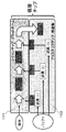
- FIG. 2 is a schematic diagram showing components of the DNA analysis microchannel chip of the present disclosure.
- the material of the chip A is silicon, and a channel and a structure are dug on the silicon substrate by photolithography and RIE (reactive ion gas etching).
- RIE reactive ion gas etching
- a mixer 205 and a filter 206 are used. And connect as shown.
- the material of the chip B is plastic, and it is preferable to use PMMA (polymethyl methacrylate resin) or PDMS (polydimethylsiloxy acid). Moreover, it is preferable to use an adhesive layer or an elastomer for the connection portion with the silicon layer.
- the reagent (3) used for the sensor is arranged in this chip. The specimen is injected through hole 207, reagent (1), and reagent (2) through hole 208 and hole 209, respectively. The reagent may be freeze-dried, and the buffer solution may be poured and dissolved before use.
- the chip B has a liquid feeding mechanism, a pump 210 and a valve 211 are arranged, and a function of pouring the reagent into the chip A is controlled, and the input amount and timing are controlled.
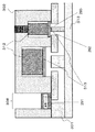
- FIG. 3A and FIG. 3B are schematic cross-sectional views showing components of the DNA analysis microchannel chip of the present disclosure.
- FIG. 3A is a cross-sectional view including a reagent, a pump, and a valve.
- the valve 311 is embedded in a plastic part so that it can be easily detached.
- the actuator 312 of the pump drive unit may be a piezo element or a polymer actuator, and is arranged so that the membrane 313 can be moved up and down.
- a polymer actuator Assuming that the chip is used disposable, it is particularly preferred to use a polymer actuator. As shown in the figure, these are connected to a port and a channel formed of silicon on the lower surface, and liquid feeding can be performed in the silicon layer.
- the microchannel of the silicon layer is patterned from the lower surface by photolithography and RIE. Further, Pyrex glass 314 is used as a lid in order to seal the patterned flow path. The Pyrex glass 314 is bonded to the silicon surface by an anodic oxidation method. Further, in order to connect the plastic and silicon micro-channels, a through hole is formed from the upper surface before joining the plastic layer.
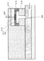
- FIG. 3B is a cross-sectional view of a portion including the sensor.
- the sensor chip 315 is arranged so that the detection surface 316 faces the lower surface.
- the sensor chip 317 is preferably in a detachable state.
- the reagent (3) may be dry-chemized on the detection surface and held in the cavity 318.
- a spacer 319 may be provided in the case where the distance between the sensor chip and the silicon chip is long. Since air needs to be degassed when the liquid is sent to the sensor cavity, an air hole 320 may be provided on the upper surface.
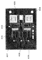
- FIG. 4 is a layout diagram of components included in the silicon chip used in the embodiment of the present disclosure.
- the thickness of the silicon substrate is preferably about 500 to 800 ⁇ m.
- Each part is etched from the top and bottom surfaces using two masks.
- the area around PCR1 403 and PCR2 404 is etched from both the upper and lower surfaces by RIE, and is completely dug out and thermally isolated.
- the flow path and mixer 405 and the micro sieve 406 are formed by etching a depth of about 300 ⁇ m from the lower surface by RIE, and Pyrex glass is anodically bonded to block the surface.
- the through-holes at the connection portions between the holes 407, 408, and 409 and the plastic portion are formed by etching to a depth of about 300 ⁇ m from the upper surface by RIE.
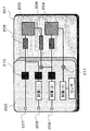
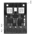
- FIG. 5 shows a layout diagram of components included in the plastic chip of the present disclosure.
- a polymer actuator pump is mounted at a position 510, and a polymer actuator valve is mounted at a position 511. Further, a sensor is connected to the reference numeral 515.
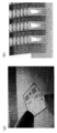
- FIG. 6 (a) is a photograph of the silicon chip portion of the DNA analysis microchannel chip actually fabricated according to the present embodiment.
- FIG. 6B is a photograph of the filter part actually produced by the method of the present embodiment.
- FIG. 7 is a photograph of a plastic chip of a DNA analysis microchannel chip actually manufactured according to the embodiment and a silicon chip bonded thereto.
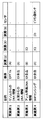
- FIG. 8 is a table summarizing examples in which the DNA analysis microchip of the present disclosure described in the embodiment is used for four types of purposes.
- the composition of the reagent is described below.
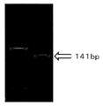
- Example 1 Extraction and amplification of desired DNA fragment containing 114th base of exon 12 of acetaldehyde dehydrogenase 2 (ALDH2) gene from human genome sample using DNA analysis microchannel chip according to one embodiment of present disclosure Went. Primer 1 and Primer 2 described above were used as primers, and an attempt was made to extract and amplify a DNA fragment having a fragment length of 141 bp.
- (A) was used, and after stirring with the sample with a mixer, the reaction in the PCR1 reactor was subjected to PCR for 30 cycles under the conditions of 98 ° C. for 30 seconds, 60 ° C. for 30 seconds, and 68 ° C. for 30 seconds. Then pass through the filter and PCR2 as they are. 3 ⁇ L of this was collected. Thereafter, the presence or absence of DNA amplification was confirmed by agarose gel electrophoresis.
- the second lane in FIG. 9 shows the result of the presence or absence of amplification of the DNA fragment collected from the sample. As shown in the second lane (L2) of FIG. 9, it was confirmed that the desired DNA fragment (141 bp) was amplified.
- Example 2 DNA amplification was performed from a blood sample using a DNA analysis microchannel chip according to an embodiment of the present disclosure.
- a model for DNA amplification AB type and O type blood were used as templates.
- a DNA fragment containing the 261st base of exon 6 in the genome of human blood was extracted and amplified.
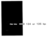
- primer Primer 3 and Primer 4 described above were used, and an attempt was made to extract and amplify a DNA fragment having a fragment length of 134 or 135 bp.
- (B) was used, and after stirring with the sample using a mixer, the reaction in the PCR1 reactor was performed for 35 cycles under conditions of 98 ° C. for 30 seconds, 60 ° C. for 30 seconds, and 68 ° C. for 30 seconds. Subsequently, unnecessary blood cell components crushed by the PCR reactor were removed by passing through a filter. The sample was passed through the PCR2 reactor as it was, 3 ⁇ L of this sample solution was collected, and the presence or absence of DNA amplification was confirmed by electrophoresis.
- the second lane in FIG. 10 is the result of the presence or absence of amplification of a DNA fragment collected from a sample of AB type and the third lane of O type. As shown in FIG. 10, it was confirmed that DNA was amplified for both AB (135 bp) and O (134 bp).
- Allele-specific DNA amplification was performed from a blood sample using the DNA analysis microchannel chip according to an embodiment of the present disclosure.
- AB type and O type blood were used as templates.
- Primer 3 and Primer 4 described above were used as primers for amplifying a DNA fragment containing the 261st base (SNP site) of the sixth exon of the human genome.
- Measurement was performed using Primer 3 ′ and Primer 4 as allele-specific primers that discriminate the difference of the 261nd base (SNP site) of the sixth exon.
- This allele-specific primer causes an extension reaction specifically only for AB type blood.
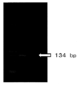
- (B) was used, and after stirring with the sample using a mixer, the reaction in the PCR1 reactor was performed for 35 cycles under conditions of 98 ° C. for 30 seconds, 60 ° C. for 30 seconds, and 68 ° C. for 30 seconds. Then, after removing impurities with a micro sieve, (C) was used as reagent 2, and PCR was performed for 30 cycles under conditions of 95 ° C. for 30 seconds, 60 ° C. for 30 seconds, and 72 ° C. for 30 seconds. 3 ⁇ L of this sample solution was collected, and the presence or absence of allele-specific DNA amplification was confirmed by electrophoresis.
- the second lane in FIG. 11 is the result of the presence or absence of amplification of a DNA fragment collected from a sample of AB type and the third lane of O type. As shown in FIG. 11, it was confirmed that only AB specifically amplified DNA.
- Example 4 An example in which SNP detection is performed from a blood sample using the DNA analysis microchannel chip according to an embodiment of the present disclosure will be described.
- AB type and O type blood were used as templates as SNP detection models.
- the kind of primer used is the same as in Example 3.
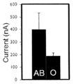
- reagent 1 For reagent 1, (B) was used, and after stirring with the sample using a mixer, the reaction in the PCR1 reactor was performed for 35 cycles under conditions of 98 ° C. for 30 seconds, 60 ° C. for 30 seconds, and 68 ° C. for 30 seconds. Thereafter, the filter is passed through to remove unnecessary blood cell components crushed by the PCR reactor, and then mixed with the reagent 2 by the mixer 2 and introduced into the PCR2 reactor. PCR was performed for 30 cycles under the conditions of 30 ° C., 30 seconds at 60 ° C., and 30 seconds at 72 ° C.
- DNA extraction, amplification, or detection of the sequence thereof can be performed quickly and easily, and at the same time, the chip can be used for various purposes. Rise. Expected to contribute to tailor-made medical care.
Landscapes
- Chemical & Material Sciences (AREA)
- Health & Medical Sciences (AREA)
- Chemical Kinetics & Catalysis (AREA)
- Life Sciences & Earth Sciences (AREA)
- General Health & Medical Sciences (AREA)
- Organic Chemistry (AREA)
- Analytical Chemistry (AREA)
- Clinical Laboratory Science (AREA)
- Zoology (AREA)
- Proteomics, Peptides & Aminoacids (AREA)
- Engineering & Computer Science (AREA)
- Wood Science & Technology (AREA)
- Biochemistry (AREA)
- Molecular Biology (AREA)
- Dispersion Chemistry (AREA)
- Hematology (AREA)
- Biophysics (AREA)
- Microbiology (AREA)
- Immunology (AREA)
- Biotechnology (AREA)
- Physics & Mathematics (AREA)
- Bioinformatics & Cheminformatics (AREA)
- General Engineering & Computer Science (AREA)
- Genetics & Genomics (AREA)
- Apparatus Associated With Microorganisms And Enzymes (AREA)
- Measuring Or Testing Involving Enzymes Or Micro-Organisms (AREA)
Abstract
Description
非特許文献1では、プラスチックとシリコンを積層し、マイクロ流路チップと送液部を分けて配置する構造が開示されている。しかしながら、この方法によると、サーマルリアクタがプラスチック材料で構成されている上、そのリアクタがガラス基板を挟んで加熱面であるシリコンから隔離されているため熱接触が非常に取りにくく、熱伝達が悪いため、高速な昇降温には対応できない。また、検体や試薬をチップ外部から供給する構造になっているため、簡便に使用できない。そのため、迅速・簡便な処理に向かないことが問題であった。
シリコンからなる第1層(101)および
プラスチックからなる第2層(102)
を具備し、ここで、
前記第2層(102)が前記検体の種類および解析される対象物に応じて可変的に選択されるように、前記第2層(102)は前記第1層(101)上に積層され、
前記第1層(101)は、
少なくとも4個の開口部(291、292、293、294)
2以上のPCRリアクタ(203、204、403、404)、および
前記開口部および各PCRリアクタの間と連通するマイクロ流路
を具備し、
前記第2層(102)は、
前記PCR法のために用いられる試薬(1、2)、
ポンプ(312)、
センサ(315)
を具備し、
第1層(101)の法線方向から見たときに、前記試薬(1、2)は、前記複数の開口部の少なくとも1つの開口部に重なり合い、
第1層(101)の法線方向から見たときに、前記ポンプ(312)は、前記複数の開口部の少なくとも2つの開口部に重なり合い、
前記ポンプにより、前記試薬は、前記マイクロ流路を介して前記PCRリアクタに供給され、
前記PCRリアクタには、前記試薬および前記検体の混合物が供給され、
前記混合物は、前記PCRリアクタから前記センサに送られ、前記センサを用いて前記検体に含有されるDNAをPCR法により解析する。
シリコンからなる第1層(101)および
プラスチックからなる第2層(102)
を具備し、ここで、
前記第2層(102)が前記検体の種類および解析される対象物に応じて可変的に選択されるように、前記第2層(102)は前記第1層(101)上に積層され、
前記第1層(101)は、
少なくとも4個の開口部(291、292、293、294)、
2以上のPCRリアクタ(203、204、403、404)、
前記PCRリアクタの間に設けられた少なくとも1つのフィルタ(206)、および
前記開口部、各PCRリアクタおよび前記少なくとも1つのフィルタの間と連通するマイクロ流路
を具備し、
前記第2層(102)は、
前記PCR法のために用いられる試薬(1、2)、
ポンプ(312)、および
センサ(315)
を具備し、
第1層(101)の法線方向から見たときに、前記試薬(1、2)は、前記少なくとも4個の開口部に含まれる少なくとも1つの開口部(291)に重なり合い、
第1層(101)の法線方向から見たときに、前記ポンプ(312)は、前記少なくとも4個の開口部に含まれる少なくとも2つの開口部(292、293)に重なり合い、
前記ポンプにより、前記試薬は、前記マイクロ流路を介して前記PCRリアクタに供給され、
前記PCRリアクタには、前記試薬および前記検体の混合物が供給され、
前記混合物は、前記PCRリアクタから前記少なくとも4個の開口部に含まれる少なくとも1つの開口部(294)を介して前記センサに送られ、前記センサを用いて前記検体に含有されるDNAを解析する。
上記のように、PCRリアクタの外周部を概ね掘り抜いて、周辺部と熱的に分離された構造とすることによって、リアクタ外周部への放熱、外周部からの吸熱を抑制できるため、より高速な昇降温が可能なPCRができるようになり、より迅速なDNA解析が行える。
上記のように、ピラー間の間隔を10μm以下、1μm以上とすることによって、検体に血液を用いたとき、PCRリアクタで破砕された不要な血球成分を、フィルタを目詰まりさせることなく、フィルタで効率的に取り除くことができる。
上記のように送液機構(例えば、ポンプ)にポリマーアクチュエータを用いることによって、送液を行うことに対して高い発生力が得られるため、フィルタでの検体由来物質の目詰まりを起こしにくい。さらに、送液機構(例えば、バルブ)にポリマーアクチュエータを用いることによって、送液を止めることに対して、高い耐圧性が得られるため、流路へのリークを抑制することができる。これらより、安定したチップ動作が行える。
第1層(101)および複数の第2層(102)を用意する工程(a)、ここで、
前記第1層(101)は、シリコンからなり、
前記第1層(101)は、
少なくとも4個の開口部(291、292、293、294)、
2以上のPCRリアクタ(203、204、403、404)、
前記PCRリアクタの間に設けられた少なくとも1つのフィルタ(206)、および
前記開口部、各PCRリアクタおよび前記少なくとも1つのフィルタの間と連通するマイクロ流路
を具備し、
各第2層(102)は、プラスチックからなり、
各第2層(102)は、
前記PCR法のために用いられる試薬(1、2)、
ポンプ(312)、および
センサ(315)
を具備し、
前記複数の第2層(102)の中から、前記検体の種類および解析される対象物に応じて1つの第2層(102)を選択する工程(b)、
工程(b)において選択された第2層を前記第1層(101)上に積層し、DNA解析マイクロ流路チップを得る工程(c)、ここで、
第1層(101)の法線方向から見たときに、前記試薬(1、2)は、前記少なくとも4個の開口部に含まれる少なくとも1つの開口部(291)に重なり合い、かつ
第1層(101)の法線方向から見たときに、前記ポンプ(312)は、前記少なくとも4個の開口部に含まれる少なくとも2つの開口部(292、293)に重なり合い、
前記DNA解析マイクロ流路チップの内部に、前記検体を供給する工程(d)、
前記ポンプにより、前記試薬を、前記マイクロ流路を介して前記PCRリアクタに供給する工程(e)、
ここで、前記PCRリアクタには、前記試薬および前記検体の混合物が供給され、
前記PCRリアクタにおいて、前記PCR法を実施し、PCR生成物を得る工程(f)、
前記工程(f)において得られたPCR生成物を、前記PCRリアクタから前記少なくとも4個の開口部に含まれる少なくとも1つの開口部(294)を介して前記センサに送る工程(g)、および
前記センサを用いて前記PCR生成物を感知して、前記検体に含有されるDNAを解析する工程(h)
を含む。
以下を具備するDNA解析マイクロ流路チップを用意する工程(a’)
シリコンからなる第1層(101)および
プラスチックからなる第2層(102)、ここで、
前記第2層(102)は前記第1層(101)上に積層され、
前記第1層(101)は、
少なくとも4個の開口部(291、292、293、294)、
2以上のPCRリアクタ(203、204、403、404)、
前記PCRリアクタの間に設けられた少なくとも1つのフィルタ(206)、および
前記開口部、各PCRリアクタおよび前記少なくとも1つのフィルタの間と連通するマイクロ流路
を具備し、
前記第2層(102)は、
前記PCR法のために用いられる試薬(1、2)、
ポンプ(312)、および
センサ(315)
を具備し、
第1層(101)の法線方向から見たときに、前記試薬(1、2)は、前記少なくとも4個の開口部に含まれる少なくとも1つの開口部(291)に重なり合い、かつ
第1層(101)の法線方向から見たときに、前記ポンプ(312)は、前記少なくとも4個の開口部に含まれる少なくとも1つの開口部(292、293)に重なり合い、
前記DNA解析マイクロ流路チップの内部に、前記検体を供給する工程(d)、
前記ポンプにより、前記試薬を、前記マイクロ流路を介して前記PCRリアクタに供給する工程(e)、
ここで、前記PCRリアクタには、前記試薬および前記検体の混合物が供給され、
前記PCRリアクタにおいて、前記PCR法を実施し、PCR生成物を得る工程(f)、
前記工程(f)において得られたPCR生成物を、前記PCRリアクタから前記少なくとも4個の開口部に含まれる少なくとも1つの開口部(294)を介して前記センサに送る工程(g)、および
前記センサを用いて前記PCR生成物を感知して、前記検体に含有されるDNAを解析する工程(h)、
を含む。
図1は、本開示のマイクロ流路チップの全般的概念図である。本開示におけるDNA解析マイクロ流路チップは、シリコン層101(チップA)とプラスチック層102(チップB)が積層された構造を有する。前記チップAは、マイクロ流路中に少なくとも2つ以上直列に接続されたPCRリアクタと、前記PCRリアクタ間に複数本のシリコンピラーで構成される少なくとも1つのフィルタを具備し、前記チップBは、マイクロ流路中に試薬、送液機構およびセンサを具備し、かつ前記試薬、送液機構およびセンサは、検体の種類および検出対象によって可変できることを特徴とする。検体や試薬の投入や各処理は図1の矢印の順番に進む。
図3(a)は、試薬、ポンプ、バルブを含む断面図である。ポンプ310は、バルブ311は、プラスチック部に埋め込まれ、脱着が容易にできるようになっている。ポンプの駆動部のアクチュエータ312は、ピエゾ素子やポリマーアクチュエータを用いるとよく、メンブレン313を上下できるように配置される。チップが使い捨てで使われることを想定すると、ポリマーアクチュエータを用いることが特に好ましい。図に示す通り、これらは下面のシリコンで形成されたポートと流路に接続され、シリコン層内での送液が行うことができる。シリコン層のマイクロ流路は、下面から、フォトリソグラフィとRIEによってパターニングされる。また、パターニングされた流路を密閉させるために、パイレックスガラス314を蓋として用いる。パイレックスガラス314は、陽極酸化法でシリコン面に対して接合されている。また、プラスチックとシリコンのマイクロ流路を接続するために、プラスチック層を接合する前に上面から貫通穴を形成している。
シリコン基板の厚さは500~800μm程度が好ましい。2枚のマスクを用いて上面および下面からそれぞれのパーツがエッチングされる。PCR1の403、PCR2の404の周りは概ねRIEにより上面および下面の両面からエッチングされ、完全に掘り抜かれ、熱的に孤立している。一方で、流路およびミキサー405、マイクロシーブ406は、RIEによって下面より約300μmの深さをエッチングして形成され、パイレックスガラスを陽極酸化接合し、表面がふさがれている。孔407,408,409とプラスチック部との接続部の貫通穴は、RIEによって上面より約300μmの深さをエッチングして形成されている。
(A)タカラバイオ製のTaq−ポリメラーゼ:0.2・L、PCR mix:3・L、水:2μL、2mMdNTP:1・L、10・M Primer1:1・L、10・M Primer2:1・L(それぞれのPrimer配列は※に記載)
(B)東洋紡製KOD−FXポリメラーゼ:0.2・L、2×KOD−Buffer:5・L、2mMdNTP: 1・L、10・M Primer3:1・L、10・M Primer4:1・L (それぞれのPrimer配列は※に記載)
(C)タカラバイオ製のTaq−ポリメラーゼ:0.2・L、PCR mix:3・L、Primer3‘:2・L、Primer4:2・L、蒸留水10.8・L (それぞれのPrimer配列は※に記載)
(D) トリシン緩衝液(pH8.8) 1.8μL 45mM
酸化型ニコチンアミドジヌクレオチド 0.2μL 1mM
塩化マグネシウム 0.4μL 1.7mM
フェリシアン化カリウム 2μL 10mM
グリセルアルデヒド−3−リン酸 0.66μL 10mM
ジアホラーゼ 1μL 10U/mL
グリセルアルデヒド−3−リン酸デヒドロゲナーゼ 1μL 32U/mL
ピロホスファターゼ 0.5μL 5U/mL
※Primer1(5‘−ACGGGCTGCAGGCATACACT−3‘:配列番号1)、Primer2(5’−GGC AGG TCC TGA ACC TC−3’:配列番号2)、Primer3(5‘−TAGGAAGGATGTCCTCG−3’:配列番号3)、Primer3‘(5’−TAGGAAGGATGTCCTCGTGACG−3’:配列番号4)、およびPrimer4(5’−TTCTTGATGGCAAACACAGTTAAC−3’:配列番号5)
本開示の一実施の形態に係るDNA解析マイクロ流路チップを用いて、ヒトゲノム検体からアセトアルデヒド脱水素酵素2(ALDH2)遺伝子の第12エクソンの114番目の塩基を含む所望のDNA断片の抽出・増幅を行った。プライマーは、前述したPrimer1およびPrimer2を用い、断片長141bpのDNA断片の抽出・増幅を試みた。
本開示の一実施の形態に係るDNA解析マイクロ流路チップを用いて、血液検体からDNA増幅を行った。DNA増幅のモデルとして、テンプレートとしてAB型とO型それぞれの血液を用いた。ヒト血液のゲノム中の第6エクソンの261番目の塩基を含む、DNA断片の抽出・増幅行った。プライマーとして、プライマーは前述したPrimer3およびPrimer4を用い、断片長134又は135bpのDNA断片の抽出・増幅を試みた。
本開示の一実施の形態に係るDNA解析マイクロ流路チップを用いて、血液検体からアレル特異DNA増幅を行った。アレル特異DNA増幅のモデルとして、テンプレートとしてAB型とO型それぞれの血液を用いた。ヒトゲノムの第六エクソンの261番目の塩基(SNP部位)を含むDNA断片を増幅するプライマーとして、前述したPrimer3およびPrimer4を用いた。第六エクソンの261番目の塩基(SNP部位)の違いを見分けるアレル特異性プライマーとして、Primer3‘、Primer4を用いて測定を行った。このアレル特異性プライマーはAB型の血液に対してのみ特異的に伸長反応を起こす。
本開示の一実施の形態に係るDNA解析マイクロ流路チップを用いて、血液検体からSNP検出を行った実施例について説明する。
例3と同様、SNP検出のモデルとして、テンプレートとしてAB型とO型それぞれの血液を用いた。用いたプライマーの種類は例3と同様である。
102 プラスチック基板
203 PCR1
204 PCR2
205 ミキサー
206 フィルタ
207 孔(検体)
208 孔(試薬1)
209 孔(試薬2)
210、310 ポンプ
211、311 バルブ
312 アクチュエータ
313 メンブレン
314 パイレックスガラス
315 センサチップ
316 検出面
317 試薬3
318 キャビティ
319 スペーサ
320 空気穴
Claims (6)
- 検体に含有されるDNAをPCR法により解析するために用いられるDNA解析マイクロ流路チップであって、
シリコンからなる第1層(101)および
プラスチックからなる第2層(102)
を具備し、ここで、
前記第2層(102)が前記検体の種類および解析される対象物に応じて可変的に選択されるように、前記第2層(102)は前記第1層(101)上に積層され、
前記第1層(101)は、
少なくとも4個の開口部(291、292、293、294)、
2以上のPCRリアクタ(203、204、403、404)、
前記PCRリアクタの間に設けられた少なくとも1つのフィルタ(206)、および
前記開口部、各PCRリアクタおよび前記少なくとも1つのフィルタの間と連通するマイクロ流路
を具備し、
前記第2層(102)は、
前記PCR法のために用いられる試薬(1、2)、
ポンプ(312)、および
センサ(315)
を具備し、
第1層(101)の法線方向から見たときに、前記試薬(1、2)は、前記少なくとも4個の開口部に含まれる少なくとも1つの開口部(291)に重なり合い、
第1層(101)の法線方向から見たときに、前記ポンプ(312)は、前記少なくとも4個の開口部に含まれる少なくとも2つの開口部(292、293)に重なり合い、
前記ポンプにより、前記試薬は、前記マイクロ流路を介して前記PCRリアクタに供給され、
前記PCRリアクタには、前記試薬および前記検体の混合物が供給され、
前記混合物は、前記PCRリアクタから前記少なくとも4個の開口部に含まれる少なくとも1つの開口部(294)を介して前記センサに送られ、前記センサを用いて前記検体に含有されるDNAを解析する、DNA解析マイクロ流路チップ。 - 請求項1記載のDNA解析マイクロ流路チップにおいて、前記PCRリアクタの周辺部のうち、マイクロ流路と接続されている付近以外のシリコン領域が掘り抜かれていることを特徴とする、DNA解析マイクロ流路チップ。
- 請求項1記載のDNA解析マイクロ流路チップにおいて、前記フィルタは、シリコンのエッチングで形成された円柱形状のピラーにより構成され、前記ピラー間の間隔が10μm以下、1μm以上であることを特徴とする、DNA解析マイクロ流路チップ。
- 請求項1記載のDNA解析マイクロ流路チップにおいて、前記送液機構にポリマーアクチュエータを用いることを特徴とする、DNA解析マイクロ流路チップ。
- 検体に含有されるDNAをPCR法により解析する方法であって、
第1層(101)および複数の第2層(102)を用意する工程(a)、ここで、
前記第1層(101)は、シリコンからなり、
前記第1層(101)は、
少なくとも4個の開口部(291、292、293、294)、
2以上のPCRリアクタ(203、204、403、404)、
前記PCRリアクタの間に設けられた少なくとも1つのフィルタ(206)、および
前記開口部、各PCRリアクタおよび前記少なくとも1つのフィルタの間と連通するマイクロ流路
を具備し、
各第2層(102)は、プラスチックからなり、
各第2層(102)は、
前記PCR法のために用いられる試薬(1、2)、
ポンプ(312)、および
センサ(315)
を具備し、
前記複数の第2層(102)の中から、前記検体の種類および解析される対象物に応じて1つの第2層(102)を選択する工程(b)、
工程(b)において選択された第2層を前記第1層(101)上に積層し、DNA解析マイクロ流路チップを得る工程(c)、ここで、
第1層(101)の法線方向から見たときに、前記試薬(1、2)は、前記少なくとも4個の開口部に含まれる少なくとも1つの開口部(291)に重なり合い、かつ
第1層(101)の法線方向から見たときに、前記ポンプ(312)は、前記少なくとも4個の開口部に含まれる少なくとも2つの開口部(292、293)に重なり合い、
前記DNA解析マイクロ流路チップの内部に、前記検体を供給する工程(d)、
前記ポンプにより、前記試薬を、前記マイクロ流路を介して前記PCRリアクタに供給する工程(e)、
ここで、前記PCRリアクタには、前記試薬および前記検体の混合物が供給され、
前記PCRリアクタにおいて、前記PCR法を実施し、PCR生成物を得る工程(f)、
前記工程(f)において得られたPCR生成物を、前記PCRリアクタから前記少なくとも4個の開口部に含まれる少なくとも1つの開口部(294)を介して前記センサに送る工程(g)、および
前記センサを用いて前記PCR生成物を感知して、前記検体に含有されるDNAを解析する工程(h)
を含む、検体に含有されるDNAをPCR法により解析する方法。 - 検体に含有されるDNAをPCR法によりDNA解析マイクロ流路チップを用いて解析する方法であって、
以下を具備するDNA解析マイクロ流路チップを用意する工程(a’)
シリコンからなる第1層(101)および
プラスチックからなる第2層(102)、ここで、
前記第2層(102)は前記第1層(101)上に積層され、
前記第1層(101)は、
少なくとも4個の開口部(291、292、293、294)、
2以上のPCRリアクタ(203、204、403、404)、
前記PCRリアクタの間に設けられた少なくとも1つのフィルタ(206)、および
前記開口部、各PCRリアクタおよび前記少なくとも1つのフィルタの間と連通するマイクロ流路
を具備し、
前記第2層(102)は、
前記PCR法のために用いられる試薬(1、2)、
ポンプ(312)、および
センサ(315)
を具備し、
第1層(101)の法線方向から見たときに、前記試薬(1、2)は、前記少なくとも4個の開口部に含まれる少なくとも1つの開口部(291)に重なり合い、かつ
第1層(101)の法線方向から見たときに、前記ポンプ(312)は、前記少なくとも4個の開口部に含まれる少なくとも1つの開口部(292、293)に重なり合い、
前記DNA解析マイクロ流路チップの内部に、前記検体を供給する工程(d)、
前記ポンプにより、前記試薬を、前記マイクロ流路を介して前記PCRリアクタに供給する工程(e)、
ここで、前記PCRリアクタには、前記試薬および前記検体の混合物が供給され、
前記PCRリアクタにおいて、前記PCR法を実施し、PCR生成物を得る工程(f)、
前記工程(f)において得られたPCR生成物を、前記PCRリアクタから前記少なくとも4個の開口部に含まれる少なくとも1つの開口部(294)を介して前記センサに送る工程(g)、および
前記センサを用いて前記PCR生成物を感知して、前記検体に含有されるDNAを解析する工程(h)、
を含む、検体に含有されるDNAをPCR法によりDNA解析マイクロ流路チップを用いて解析する方法。
Priority Applications (3)
| Application Number | Priority Date | Filing Date | Title |
|---|---|---|---|
| JP2013557966A JP5583290B2 (ja) | 2012-04-20 | 2013-04-19 | Dna解析マイクロ流路チップ |
| EP13778172.0A EP2840129B1 (en) | 2012-04-20 | 2013-04-19 | Dna chip with micro-channel for dna analysis |
| US14/196,293 US10100352B2 (en) | 2012-04-20 | 2014-03-04 | DNA chip with micro-channel for DNA analysis |
Applications Claiming Priority (2)
| Application Number | Priority Date | Filing Date | Title |
|---|---|---|---|
| JP2012096885 | 2012-04-20 | ||
| JP2012-096885 | 2012-04-20 |
Related Child Applications (1)
| Application Number | Title | Priority Date | Filing Date |
|---|---|---|---|
| US14/196,293 Continuation US10100352B2 (en) | 2012-04-20 | 2014-03-04 | DNA chip with micro-channel for DNA analysis |
Publications (1)
| Publication Number | Publication Date |
|---|---|
| WO2013157667A1 true WO2013157667A1 (ja) | 2013-10-24 |
Family
ID=49383605
Family Applications (1)
| Application Number | Title | Priority Date | Filing Date |
|---|---|---|---|
| PCT/JP2013/062310 Ceased WO2013157667A1 (ja) | 2012-04-20 | 2013-04-19 | Dna解析マイクロ流路チップ |
Country Status (4)
| Country | Link |
|---|---|
| US (1) | US10100352B2 (ja) |
| EP (1) | EP2840129B1 (ja) |
| JP (1) | JP5583290B2 (ja) |
| WO (1) | WO2013157667A1 (ja) |
Cited By (3)
| Publication number | Priority date | Publication date | Assignee | Title |
|---|---|---|---|---|
| CN106195321A (zh) * | 2016-08-30 | 2016-12-07 | 博奥颐和健康科学技术(北京)有限公司 | 一种液体存储和释放组件及液体存储和释放芯片 |
| WO2018109829A1 (ja) * | 2016-12-13 | 2018-06-21 | 栄研化学株式会社 | マイクロチップ |
| WO2022034866A1 (ja) * | 2020-08-11 | 2022-02-17 | 杏林製薬株式会社 | 核酸増幅チップ |
Families Citing this family (6)
| Publication number | Priority date | Publication date | Assignee | Title |
|---|---|---|---|---|
| CN106701556B (zh) * | 2017-01-06 | 2019-02-12 | 广东顺德永诺生物科技有限公司 | 数字pcr检测装置及其液路系统 |
| US20210170396A1 (en) | 2018-01-16 | 2021-06-10 | Hewlett-Packard Development Company, L.P. | Fluid testing |
| US11731126B2 (en) | 2018-04-19 | 2023-08-22 | Nanyang Technological University | Microfluidic board and method of forming the same |
| CN110849868B (zh) * | 2019-10-21 | 2022-09-13 | 江苏大学 | 基于微流控芯片的面粉中溴酸钾智能检测装置与方法 |
| CN110791422B (zh) * | 2019-11-08 | 2021-07-20 | 宁波胤瑞生物医学仪器有限责任公司 | 一种核酸扩增仪的调控方法 |
| US11986821B2 (en) * | 2019-11-13 | 2024-05-21 | Beijing Boe Health Technology Co., Ltd. | Detection chip |
Citations (2)
| Publication number | Priority date | Publication date | Assignee | Title |
|---|---|---|---|---|
| JP2011522219A (ja) * | 2008-04-10 | 2011-07-28 | ヴァルティオン・テクニッリネン・トゥトキムスケスクス | マイクロ流体チップ装置およびその使用 |
| US20130078155A1 (en) * | 2011-09-23 | 2013-03-28 | Imec | Method and Device for Thermal Insulation of Micro-Reactors |
Family Cites Families (5)
| Publication number | Priority date | Publication date | Assignee | Title |
|---|---|---|---|---|
| WO2004034028A2 (en) * | 2002-10-09 | 2004-04-22 | The Board Of Trustees Of The University Of Illinois | Microfluidic systems and components |
| US20050142565A1 (en) * | 2003-12-30 | 2005-06-30 | Agency For Science, Technology And Research | Nucleic acid purification chip |
| CA2559778C (en) * | 2004-03-26 | 2011-07-05 | Infectio Recherche Inc. | Removable microfluidic flow cell |
| KR100773563B1 (ko) * | 2006-11-14 | 2007-11-07 | 삼성전자주식회사 | 미세유체 처리 소자를 포함한 미세유체 처리 장치 및 이의제조방법 |
| US20090227476A1 (en) * | 2008-03-07 | 2009-09-10 | Applied Microarrays, Inc. | Amplification and microarray detection apparatus and methods of making |
-
2013
- 2013-04-19 JP JP2013557966A patent/JP5583290B2/ja not_active Expired - Fee Related
- 2013-04-19 EP EP13778172.0A patent/EP2840129B1/en active Active
- 2013-04-19 WO PCT/JP2013/062310 patent/WO2013157667A1/ja not_active Ceased
-
2014
- 2014-03-04 US US14/196,293 patent/US10100352B2/en active Active
Patent Citations (2)
| Publication number | Priority date | Publication date | Assignee | Title |
|---|---|---|---|---|
| JP2011522219A (ja) * | 2008-04-10 | 2011-07-28 | ヴァルティオン・テクニッリネン・トゥトキムスケスクス | マイクロ流体チップ装置およびその使用 |
| US20130078155A1 (en) * | 2011-09-23 | 2013-03-28 | Imec | Method and Device for Thermal Insulation of Micro-Reactors |
Non-Patent Citations (9)
| Title |
|---|
| BIOMED MICRODEVICE, vol. 13, 2011, pages 19 - 27 |
| ICHIRO YAMASHITA ET AL.: "Realizing rapid on- site SNP (Single Nucleotide Polymorphism) Diagnosis", PANASONIC TECHNICAL JOURNAL, vol. 57, no. 3, 15 October 2011 (2011-10-15), pages 21 - 26, XP008173315 * |
| LEE, D.S. ET AL.: "Bulk-micromachined submicroliter-volume PCR chip with very rapid thermal response and low power consumption", LAB ON A CHIP, vol. 4, no. 4, 29 March 2004 (2004-03-29), pages 401 - 407, XP009047295 * |
| MAJEED, B. ET AL.: "Silicon Based System for Single-Nucleotide-Polymorphism Detection: Chip Fabrication and Thermal Characterization of Polymerase Chain Reaction Microchamber", JAPANESE JOURNAL OF APPLIED PHYSICS, vol. 51, 20 April 2012 (2012-04-20), XP003032530 * |
| MAJEED, B. ET AL.: "Silicon micro-pillar filter fabrication for DNA separation in Lab-on-chip system", ELECTRONICS PACKAGING TECHNOLOGY CONFERENCE (EPTC), 2012 IEEE 14TH, 5 December 2012 (2012-12-05), pages 52 - 56, XP032425993 * |
| MAN, P.F. ET AL.: "Microfluidic plastic capillaries on silicon substrates: a new inexpensive technology for bioanalysis chips", MICRO ELECTRO MECHANICAL SYSTEMS, 1997. MEMS '97, PROCEEDINGS, IEEE., TENTH ANNUAL INTERNATIONAL WORKSHOP, 26 January 1997 (1997-01-26), pages 311 - 316, XP010216924 * |
| PALMIERI, M. ET AL.: "Advanced Microfluidic Packaging for Molecular Diagnostics", 43RD INTERNATIONAL SYMPOSIUM ON MICROELECTRONICS 2010, (IMAPS 2010), 2010, pages 36 - 41, XP008172446 * |
| PROCEEDING OF 43RD INTERNATIONAL SYMPOSIUM ON MICROELECTRONICS (IMAPS 2010, 2010, pages 000036 |
| See also references of EP2840129A4 * |
Cited By (6)
| Publication number | Priority date | Publication date | Assignee | Title |
|---|---|---|---|---|
| CN106195321A (zh) * | 2016-08-30 | 2016-12-07 | 博奥颐和健康科学技术(北京)有限公司 | 一种液体存储和释放组件及液体存储和释放芯片 |
| CN106195321B (zh) * | 2016-08-30 | 2017-09-22 | 博奥颐和健康科学技术(北京)有限公司 | 一种液体存储和释放组件及液体存储和释放芯片 |
| US10821443B2 (en) | 2016-08-30 | 2020-11-03 | Capitalbio Ehealth Science & Technology (Beijing) Co., Ltd. | Liquid storage and release assembly and liquid storage and release chip |
| WO2018109829A1 (ja) * | 2016-12-13 | 2018-06-21 | 栄研化学株式会社 | マイクロチップ |
| WO2022034866A1 (ja) * | 2020-08-11 | 2022-02-17 | 杏林製薬株式会社 | 核酸増幅チップ |
| JPWO2022034866A1 (ja) * | 2020-08-11 | 2022-02-17 |
Also Published As
| Publication number | Publication date |
|---|---|
| JP5583290B2 (ja) | 2014-09-03 |
| EP2840129A1 (en) | 2015-02-25 |
| EP2840129B1 (en) | 2017-07-05 |
| JPWO2013157667A1 (ja) | 2015-12-21 |
| US10100352B2 (en) | 2018-10-16 |
| US20140186846A1 (en) | 2014-07-03 |
| EP2840129A4 (en) | 2015-12-30 |
Similar Documents
| Publication | Publication Date | Title |
|---|---|---|
| JP5583290B2 (ja) | Dna解析マイクロ流路チップ | |
| Yin et al. | Digital recombinase polymerase amplification, digital loop‐mediated isothermal amplification, and digital CRISPR‐Cas assisted assay: current status, challenges, and perspectives | |
| JP5523327B2 (ja) | 統合型マイクロ流体デバイスおよび方法 | |
| EP3527288B1 (en) | Methods for virus detection | |
| WO2016065300A1 (en) | Microfluidic cartridge | |
| US20080166770A1 (en) | Method and apparatus for amplifying and synthesisizing nucleic acid with denaturant | |
| Zhang et al. | Overview and future perspectives of microfluidic digital recombinase polymerase amplification (dRPA) | |
| Parthasarathy et al. | Developments in microfluidic integrated lab-on-chip devices for DNA biosensing towards unifying the emergence of nanobiosensor | |
| JP5521126B2 (ja) | Dna解析マイクロ流路チップ | |
| US20130096035A1 (en) | Self-sustained fluidic droplet cassette and system for biochemical assays | |
| JP2015192603A (ja) | マイクロ流路チップおよびその駆動方法 | |
| Becker et al. | Continuous-flow PCR using segmented flow and integrating sample preparation | |
| KR20240108803A (ko) | 신속 현장진단검사용 바이오칩 및 이를 이용한 호흡기 감염병의 다중 분자진단 | |
| Ugaz | PCR in integrated microfluidic systems | |
| Chen | Fully integrated microsystem for bacterial genotyping | |
| Chabert | Gene Expression Analysis on Microchips | |
| HK1186430B (en) | Assays | |
| HK1186499B (en) | Assays | |
| HK1144406A (en) | Assay for detecting viral nucleic acid | |
| HK1144406B (en) | Assay for detecting viral nucleic acid | |
| HK1186430A (en) | Assays | |
| HK1186499A (en) | Assays | |
| HK1190357A (en) | Microfluidic system |
Legal Events
| Date | Code | Title | Description |
|---|---|---|---|
| 121 | Ep: the epo has been informed by wipo that ep was designated in this application |
Ref document number: 13778172 Country of ref document: EP Kind code of ref document: A1 |
|
| ENP | Entry into the national phase |
Ref document number: 2013557966 Country of ref document: JP Kind code of ref document: A |
|
| REEP | Request for entry into the european phase |
Ref document number: 2013778172 Country of ref document: EP |
|
| WWE | Wipo information: entry into national phase |
Ref document number: 2013778172 Country of ref document: EP |
|
| NENP | Non-entry into the national phase |
Ref country code: DE |