WO2013157851A1 - 약제 불출 시스템 및 그 제어방법 - Google Patents
약제 불출 시스템 및 그 제어방법 Download PDFInfo
- Publication number
- WO2013157851A1 WO2013157851A1 PCT/KR2013/003256 KR2013003256W WO2013157851A1 WO 2013157851 A1 WO2013157851 A1 WO 2013157851A1 KR 2013003256 W KR2013003256 W KR 2013003256W WO 2013157851 A1 WO2013157851 A1 WO 2013157851A1
- Authority
- WO
- WIPO (PCT)
- Prior art keywords
- drug
- unit
- dispensing
- medicine
- drug delivery
- Prior art date
- Legal status (The legal status is an assumption and is not a legal conclusion. Google has not performed a legal analysis and makes no representation as to the accuracy of the status listed.)
- Ceased
Links
Images


Classifications
-
- G—PHYSICS
- G16—INFORMATION AND COMMUNICATION TECHNOLOGY [ICT] SPECIALLY ADAPTED FOR SPECIFIC APPLICATION FIELDS
- G16H—HEALTHCARE INFORMATICS, i.e. INFORMATION AND COMMUNICATION TECHNOLOGY [ICT] SPECIALLY ADAPTED FOR THE HANDLING OR PROCESSING OF MEDICAL OR HEALTHCARE DATA
- G16H40/00—ICT specially adapted for the management or administration of healthcare resources or facilities; ICT specially adapted for the management or operation of medical equipment or devices
- G16H40/60—ICT specially adapted for the management or administration of healthcare resources or facilities; ICT specially adapted for the management or operation of medical equipment or devices for the operation of medical equipment or devices
- G16H40/67—ICT specially adapted for the management or administration of healthcare resources or facilities; ICT specially adapted for the management or operation of medical equipment or devices for the operation of medical equipment or devices for remote operation
-
- A—HUMAN NECESSITIES
- A61—MEDICAL OR VETERINARY SCIENCE; HYGIENE
- A61J—CONTAINERS SPECIALLY ADAPTED FOR MEDICAL OR PHARMACEUTICAL PURPOSES; DEVICES OR METHODS SPECIALLY ADAPTED FOR BRINGING PHARMACEUTICAL PRODUCTS INTO PARTICULAR PHYSICAL OR ADMINISTERING FORMS; DEVICES FOR ADMINISTERING FOOD OR MEDICINES ORALLY; BABY COMFORTERS; DEVICES FOR RECEIVING SPITTLE
- A61J7/00—Devices for administering medicines orally, e.g. spoons; Pill counting devices; Arrangements for time indication or reminder for taking medicine
- A61J7/0076—Medicament distribution means
- A61J7/0084—Medicament distribution means for multiple medicaments
-
- G—PHYSICS
- G07—CHECKING-DEVICES
- G07F—COIN-FREED OR LIKE APPARATUS
- G07F17/00—Coin-freed apparatus for hiring articles; Coin-freed facilities or services
- G07F17/0092—Coin-freed apparatus for hiring articles; Coin-freed facilities or services for assembling and dispensing of pharmaceutical articles
-
- G—PHYSICS
- G07—CHECKING-DEVICES
- G07F—COIN-FREED OR LIKE APPARATUS
- G07F9/00—Details other than those peculiar to special kinds or types of apparatus
- G07F9/001—Interfacing with vending machines using mobile or wearable devices
-
- G—PHYSICS
- G16—INFORMATION AND COMMUNICATION TECHNOLOGY [ICT] SPECIALLY ADAPTED FOR SPECIFIC APPLICATION FIELDS
- G16H—HEALTHCARE INFORMATICS, i.e. INFORMATION AND COMMUNICATION TECHNOLOGY [ICT] SPECIALLY ADAPTED FOR THE HANDLING OR PROCESSING OF MEDICAL OR HEALTHCARE DATA
- G16H20/00—ICT specially adapted for therapies or health-improving plans, e.g. for handling prescriptions, for steering therapy or for monitoring patient compliance
- G16H20/10—ICT specially adapted for therapies or health-improving plans, e.g. for handling prescriptions, for steering therapy or for monitoring patient compliance relating to drugs or medications, e.g. for ensuring correct administration to patients
- G16H20/13—ICT specially adapted for therapies or health-improving plans, e.g. for handling prescriptions, for steering therapy or for monitoring patient compliance relating to drugs or medications, e.g. for ensuring correct administration to patients delivered from dispensers
-
- A—HUMAN NECESSITIES
- A61—MEDICAL OR VETERINARY SCIENCE; HYGIENE
- A61J—CONTAINERS SPECIALLY ADAPTED FOR MEDICAL OR PHARMACEUTICAL PURPOSES; DEVICES OR METHODS SPECIALLY ADAPTED FOR BRINGING PHARMACEUTICAL PRODUCTS INTO PARTICULAR PHYSICAL OR ADMINISTERING FORMS; DEVICES FOR ADMINISTERING FOOD OR MEDICINES ORALLY; BABY COMFORTERS; DEVICES FOR RECEIVING SPITTLE
- A61J2205/00—General identification or selection means
- A61J2205/10—Bar codes
-
- A—HUMAN NECESSITIES
- A61—MEDICAL OR VETERINARY SCIENCE; HYGIENE
- A61J—CONTAINERS SPECIALLY ADAPTED FOR MEDICAL OR PHARMACEUTICAL PURPOSES; DEVICES OR METHODS SPECIALLY ADAPTED FOR BRINGING PHARMACEUTICAL PRODUCTS INTO PARTICULAR PHYSICAL OR ADMINISTERING FORMS; DEVICES FOR ADMINISTERING FOOD OR MEDICINES ORALLY; BABY COMFORTERS; DEVICES FOR RECEIVING SPITTLE
- A61J2205/00—General identification or selection means
- A61J2205/60—General identification or selection means using magnetic or electronic identifications, e.g. chips, RFID, electronic tags
Definitions
- the present invention relates to a drug dispensing system, and more particularly to a drug storage and supply device for safe storage of medicines of various shapes and sizes and automatically supply the stored medicines at the request of a manager having the right authority.
- the present invention relates to a drug dispensing system and a control method thereof, and more particularly, registration of unique identification information in a medicine container housing a medicine and determining whether the medicine box is genuine when installed in a cabinet of a hospital or pharmacy.
- the present invention relates to a drug management system and a control method thereof capable of managing inventory and supply information of drugs through communication between cabinets, hospital servers, and producer servers.
- the present invention relates to a drug delivery system and a control method thereof, and more particularly, to a drug delivery system and a control method for discharging a drug from a drug delivery box containing a drug.
- a single dose of a medicament according to a patient's prescription may include various types and types of medicaments, and a single dose of the medicament is delivered to the patient in a basket.
- Various medications in one basket are collected in each basket according to the type and number of medications written in the patient's prescription from the box containing each medication, the basket in which the medications are collected is delivered to the patient and the patient The medicine collected in the basket will be taken.
- a medical expert such as a pharmacist needed to take out a bottle from a bottle containing a medicine manually according to a patient's prescription, and then put it into the basket. It was necessary to confirm again.
- the drug is generally used to be prepared to have a component for treating the disease, the variety is also various, and is produced in various formulations, such as tablets, powders, injections.
- An object of the present invention is to provide a drug dispensing system and a method of controlling the same so as to promptly and accurately dispense from a drug dispensing box in collecting a drug to be taken by a patient.
- Another object of the present invention is to provide a drug dispensing system and a method of controlling the same so that the drug which is easy to be broken in the process of collecting the drug is not broken in collecting the medicine to be taken by the patient.
- Yet another object of the present invention is to provide a medication dispensing system and a method of controlling the same, which can be operated more conveniently and efficiently by an administrator and / or user in collecting medication to be taken by a patient.
- Another object of the present invention is to provide a drug dispensing system and a control method for dispensing a drug quickly and accurately while simultaneously storing more drugs in collecting a drug to be taken by a patient. .
- Still another object of the present invention is to provide a drug dispensing system and a method of controlling the same, which safely stores medicines of various shapes and sizes and automatically supplies the stored medicines at the request of a manager having proper authority.
- Another object of the present invention to provide a drug dispensing system and a method of controlling the same that can safely discharge the stored drug.
- Another object of the present invention is to provide a drug dispensing system and a control method thereof that can easily manage the inventory of the drug by providing the storage information and supply information of the drug.
- Another object of the present invention is to provide a drug dispensing system and a control method that can efficiently manage the drug by using the drug storage by giving a unique identification information to the drug storage to store the drug, according to the prescription information To provide.
- Another object of the present invention is to provide a drug dispensing system and a control method for managing the drug discharge in real time by transmitting information of the medicine container mounted on the cabinet in real time with the hospital server.
- Another object of the present invention is to provide a drug dispensing system and a method of controlling the drug can be taken out and supplemented only by the administrator having a legitimate access authority by setting the access rights of the manager for drug acceptance.
- Another object of the present invention is to provide a drug dispensing system and a control method that can be traced by using the information stored in the discharge of the drug by storing the information of the drug and the manager information taken out of the drug.
- a drug storage unit for storing the drug
- a drug discharge unit for discharging the drug stored in the drug storage unit
- a communication module for communicating with the hospital server and from the hospital server through the communication module
- a drug dispensing device comprising a control unit for controlling the operation of the drug storage unit and the drug discharge unit to discharge the drug based on the received prescription information of the prescription.
- Authentication means for authenticating the access authority of the administrator to discharge the drug stored in the administrator authenticated the right to access the prescription information of the prescription may be further included.
- a display unit for displaying various menus and operation states for carrying out chemical storage and supply operation, an input unit for receiving a command to select a menu displayed on the display unit to perform a desired operation, and inventory information of the medicine stored in the chemical storage unit;
- the storage unit for storing the emission information and the access information of the manager may be further included.
- the drug dispensing device may be communicatively connected to at least one sub-device having a drug storage therein.
- the drug storage unit may be provided in a storage box that is slidably moved and detachably mounted forward from the cabinet forming the outer shape of the drug delivery device.
- Packaging unit providing a wrapping paper for packaging the discharged drug, a printing unit for printing a guide for guiding the discharged drug on a sticker, a recovery box for recovering the drug discharged and the information of the recovered drug to recognize Bar code recognition unit may be further included.
- the medicine storage unit is formed in a box shape having an upper opening, the cartridge containing a medicine cartridge and a plurality of mounting spaces for mounting the medicine cartridge and the drug cartridge is formed in which the discharge port for storing the drug and discharge the drug therein is provided,
- the chemical cartridge is mounted to be detachably stacked in the mounting space of the cartridge mounting unit, and includes a discharge opening / closing part for opening and closing the discharge opening at a lower portion thereof, and opening and closing the discharge opening and closing part according to a control signal of the controller.
- the chemical cartridge is installed on the upper surface of the opening and closing operation
- the locking means for locking and releasing the cover is installed on the rear of the chemical cartridge and the opening and closing the opening and closing the cartridge when the cartridge mounting portion
- the locking release member installed in the front of the mounting portion may include an outlet opening and closing locking portion for releasing the locking of the outlet opening and closing.
- An insertion hole into which the locking release member is inserted may be formed at a rear surface of the medicine cartridge.
- the chemical cartridge may further include a locking member penetrating through a coupling hole formed in the cartridge mounting unit and coupled to the cartridge mounting locking unit provided in the cartridge mounting unit.
- the medicine dispensing device is manufactured separately from the drug dispensing device, and further includes a medicine refilling device for opening the cover of the medicine cartridge after completion of the authorized access authority authentication, the locking means is the medicine refilling It can be unlocked only when it is mounted on the device.
- the medicine cartridge has a memory chip for storing the unique number and the stored information of the medicine given during the initial manufacturing
- the cartridge mounting portion has a memory recognition unit is installed in a position corresponding to the memory chip of the medicine cartridge
- the memory chip may include a read-only memory to prevent deletion and modification of the initially stored information.
- the drug discharge unit is moved up and down to transfer the drug discharged from the storage box to a predetermined discharge position, the collecting unit for collecting the medicine transported by the transfer unit, discharge the medicine delivered from the collecting unit to the manager And a shutter opening and closing unit for opening and closing a take-out box and a shutter provided between the collecting unit and the take-out box.
- the transfer unit includes a conveyor belt for transferring the chemicals discharged from the chemical cartridge toward the collecting unit and a lifting unit for lifting and lowering the conveyor belt, and the chemicals discharged from the chemical cartridge are on both sides of the conveyor belt.
- a seating guide for guiding the seating on the conveyor belt may be installed.
- a buffer member may be provided on at least one of the upper surface of the seating guide and the upper surface of the conveyor belt.
- One side of the collecting part is opened to receive the drug from the conveyor belt and is delivered to the take-out, and the opening side of the collecting part is provided with a transfer shutter opening and closing operation by the shutter opening and closing portion, one side of the take-out box In the opening and closing operation of the transfer shutter may be installed to take out the shutter opening and closing operation.
- the drug storage unit may include a drawer for storing a drug storage case of different shapes according to the formulation of the drug and a drawer mounting portion provided with a loading space so that the drawer is stacked in multiple stages.
- the medicine storage case is provided with a plurality of cells are formed in accordance with the shape of the medicine to be stored, the plurality of cells are provided on the upper surface of each of the opened cells to selectively shield the door, the door for detecting the opening of the door A detection unit, a door opening and closing unit installed in each cell to open and close the door, and a memory chip for storing a unique number assigned to each cell for the first production and information of a medicine contained therein, wherein the memory chip is first A read-only memory may be provided to prevent deletion and modification of the stored information.
- a drawer detecting unit for detecting the draw state of the drawer is installed, and a fixing means for fixing the drawer in the drawn state is installed at the front part of the drawer mounting unit.
- the control unit controls the operation of the door opening and closing unit to open the door of the cell in which the chemicals to be stored among the cells provided in the medicine storage case according to the detection signal of the drawer detection unit, and all the doors are closed. Only in this state, the drawer can control the operation of the fixing means to be drawn into the drawer mounting portion.
- the drug replenishment device which is manufactured separately from the drug dispensing device and opens the door provided in each cell of the drug storage case after the administrator's legitimate access authority authentication is completed is further included. May be included.
- the present invention it is possible to accurately dispense the necessary medication from the medication delivery box according to the patient's prescription.
- an efficient and quick drug dispensing operation is possible.
- the connection between the drug delivery box and the cartridge having a rail for guiding the drug delivery box when the connection between the drug delivery box and the cartridge having a rail for guiding the drug delivery box can be connected in place.
- the drug can be dispensed only at the appropriate time by having a power transmission block for allowing or limiting the external power to be delivered in the drug delivery box for delivery of the drug.
- the present invention in the drug delivery unit to transfer the drug to the drug collection device, by providing side guards on both sides of the drug delivery unit to prevent the drug released from the drug delivery box to the outside by bounce (bounce) Can be. Furthermore, by providing a buffer member inside the side guard portion, even when the drug is bounced and collides with the side guard portion, it is possible to minimize the impact to prevent damage to the drug.
- a drug storage matrix capable of storing an ampoule-type drug is provided, and a shutter device for dispensing the ampoule-type drug is provided to facilitate automatic dispensing of the ampoule drug.
- the ampoule-type drugs stored therein are sequentially dropped onto the conveyor by a shutter drop method, and the dropped ampoule-type drugs can be sequentially dispensed according to the operation of the conveyor.
- various types of cams for operating the shutters provided in the multiple layers may be provided to provide dispensing devices that meet various environments and needs.
- the dispensing of the blister drug in the blister drug dispensing box, the dispensing of the blister drug can be easily realized by the movement of the drug accommodating portion, so that the configuration can be simplified. Further, in the injection of the blister packaging medicament, the blister packaging medicament can be prevented from interfering with other components, so that the blister packaging medicament can be accurately introduced into the drug receiving portion.
- the perforation line of the medicine package can be easily detected as a premise for individually cutting the medicine package.
- the photographing area or the acquisition area of the image used for detecting the cutting line of the medicine package it is possible to efficiently and quickly detect the cutting line by minimizing the resources of the computing system consumed in the continuous image processing of the continuous image.
- the components necessary for detecting the cutting line of the medicine package are miniaturized and economically advantageous.
- the pouch-type drug dispensing box it is possible to maximize the efficiency of the operation by preventing the pouch-type drug from being broken in dispensing the pouch-type drug.
- the present invention in order to prevent breakage of drugs to be dispensed, by controlling the dispensing timing of each drug in a variety of ways, it is possible to dispense drugs quickly and efficiently and more safely.
- drug dispensing information is stored separately, and during drug dispensing operation, by dispensing drugs in consideration of drug dispensing information, the same drugs are duplicated for the same patient.
- the dispensation can be prevented beforehand.
- the present invention is effective to safely store drugs of various formulations such as injections and tablets, and to automatically discharge the stored drugs according to prescription prescription information to a manager who has been authorized to have a safe prescription and dosing.
- the present invention it is possible to prevent damage in the process of storing and discharging the chemicals produced by the glass container to improve the storage efficiency of the chemicals.
- the door of the drug stored in each cell of the drug storage case is opened only after the administrator has completed the right access authorization, and drawers are slidable to the drawer only when all the doors are closed It can prevent malfunction and damage of chemical storage case and door.
- the present invention by providing the prescription information of the prescription provided from the hospital server only to the administrator authorized access authority to accurately administer the medication prescribed to the patient, it is possible to prevent the accident of weakening due to the wrong medication.
- the storage information of the drug stored in the drug storage unit and the discharge information of the discharged drug can be synchronized with the hospital server in real time to manage the inventory of the drug integrated.
- the present invention it is possible to accurately manage the discharge information of the drug by delivering the recovered drug information to the hospital server in real time while recovering through the recovery of the effluent drug.
- the locking device in each of the front and rear of the collection box, only the administrator with the right access authority can put the medicine into the collection box, and it is possible to take out the recovered medicine after releasing each locking device.
- the storage box is formed in the same unit standard according to the chemicals to be stored in the same unit standard, because the storage box is selectively mounted and used in the cabinet of the main unit and the sub-units, the efficiency of chemical storage Can improve.
- the drug cartridge for storing the drug of various shapes and sizes can be easily attached and detached to the cartridge mounting portion, it is possible to accurately supply the drug according to the prescription information of the prescription to the administrator authorized the right access.
- the storage compartment in the event of damage or failure of the storage compartment or the cartridge mounting portion, the storage compartment can be detached from the main body after the sliding movement of the storage compartment, and can be replaced or repaired. Can improve.
- the cartridge mounting portion is formed in a multi-stage shelf structure, and the cartridge mounting portion is stacked in the mounting space of the cartridge mounting portion so that the medicine cartridge is detachably mounted, so that a large number of chemicals can be efficiently stored and all the stored chemicals are discharged.
- the medicine cartridge can be easily replenished by separating the medicine cartridge from the cartridge mounting part during the refilling operation.
- the locking release member when the chemical cartridge is mounted to the cartridge mounting portion, the locking release member is inserted through the insertion hole formed in the cartridge body while pressing the pressing end of the hinge rotating member while the hinge rotating member rotates to open and close the member. Release the bite.
- the present invention it is possible to open and close the outlet only when the chemical cartridge is mounted in the cartridge mounting portion, and in the state of being separated from the cartridge mounting portion by closing the discharge port by using the opening and closing member at all times, vibration in the movement process It is possible to prevent the accident that the drug is discharged.
- the inventory of the drug stored in the drug cartridge may be delivered to the hospital management unit in real time, thereby improving the efficiency of the drug inventory management operation performed by the hospital management unit.
- the present invention by giving identification information to the drug container to store the drug and discharge according to the prescription information, it is possible to easily manage the drug acceptance box and the drug, and to prevent drug use and illegal use of the drug Can be.
- the present invention by opening the cover provided in the medicine container to the medicine refilling device only after the access authority of the administrator is completed, it is possible to prevent the drug to be mistaken, improve the security for special drugs You can.
- the present invention it is possible to systematically manage the drug acceptance box identification information by generating and registering the unique drug acceptance box identification information to the individual drug box.
- the medicine container it is possible to drive the medicine container by identifying the medicine container for each mounting position of the cartridge mounting portion.
- the present invention by using the drug discharge status information of the medicine container in the production management unit by analyzing the drug consumption by hospital, region, period for various purposes, it is possible to improve the efficiency of the drug production management operation.
- the present invention has the effect of checking the discharge situation of the drug in real time using the drug storage box, and analyzing the consumption information using the discharge situation of the drug to improve the efficiency of the inventory management and production management operations of the drug.
- FIG. 1 is an environment diagram schematically illustrating an environment in which a drug dispensing system according to an embodiment of the present invention operates.
- FIGS 2 to 6 are diagrams for explaining various configurations of the drug delivery system according to an embodiment of the present invention.
- FIG. 7 is a block diagram for explaining a drug collection device according to an embodiment of the present invention.
- FIG. 8 is a schematic perspective view of a drug collection device according to an embodiment of the present invention.
- FIG. 9 is a schematic perspective view showing a first drug dispensing device according to the present invention.
- 10 and 11 are schematic diagrams for explaining the principle that the drug is dispensed from the drug delivery box by the drug delivery drive means according to the present invention.
- 12 and 13 are schematic perspective views showing a drug dispensing unit according to an embodiment of the present invention.
- FIG. 14 is a schematic exploded perspective view showing the drug delivery unit according to an embodiment of the present invention.
- 15 is a schematic perspective view illustrating a state in which a position moving part of a drug dispensing unit is moved in position according to an embodiment of the present invention.
- 16 and 17 are schematic views showing a state in which the rotation support portion of the drug dispensing unit according to an embodiment of the present invention is rotated.
- FIG. 18 is a schematic partial exploded perspective view showing a drug delivery unit in another embodiment of the present invention.
- FIG. 19 is a schematic perspective view showing a state in which a position moving part of a drug delivery unit is moved in position according to another embodiment of the present invention.
- 20 is a schematic perspective view showing the drug delivery driving means according to the present invention.
- Figure 21 is a schematic perspective view showing an operating state of the drug delivery drive means according to the present invention.
- Figure 22 is a schematic perspective view showing another operating state of the drug delivery drive means according to the present invention.
- Figure 23 is a schematic perspective view showing another operating state of the drug delivery drive means according to the present invention.
- 24 is a schematic perspective view for explaining that the drug delivery drive means according to the present invention can be applied to a drug delivery box of various sizes.
- FIG. 25 is a schematic perspective view showing an operating state in the case of FIG. 24.
- 26 is a perspective view illustrating a partially cut-out view of the drug delivery unit according to one embodiment.
- 27 is a perspective view showing a state of the drug delivery unit according to an embodiment.
- FIG. 28 is a perspective view illustrating a drug delivery unit having a side guard unit according to an embodiment.
- FIG. 28 is a perspective view illustrating a drug delivery unit having a side guard unit according to an embodiment.
- FIG. 29 is a side view showing a state of the drug delivery unit of FIG. 28.
- FIG. 29 is a side view showing a state of the drug delivery unit of FIG. 28.
- FIG. 30 is a perspective view showing a state of the medicine transport unit having a side guard unit according to another embodiment.
- FIG. 31 is a side view showing a state of the drug delivery unit of FIG. 30; FIG.
- FIG. 32 is a perspective view showing a state of the medicine transport unit having a side guard unit according to another embodiment.
- FIG. 33 is a side view showing a state of the drug delivery unit of FIG.
- FIG. 34 is a perspective view illustrating a cartridge in accordance with one embodiment.
- 35 and 36 are perspective views illustrating a configuration and an operation of the fixing unit according to an exemplary embodiment.
- 37 is a perspective view showing the state of the drug delivery box according to an embodiment.
- FIG. 38 is a front perspective view illustrating the bottom surface of the drug delivery box of FIG. 37.
- FIG. 38 is a front perspective view illustrating the bottom surface of the drug delivery box of FIG. 37.
- FIG. 39 is a bottom perspective view showing the back side of the medicine dispensing box of FIG. 37; FIG.
- FIG. 40 is a rear perspective view of the drug dispensing box of FIG. 37 viewed from another angle.
- FIG. 40 is a rear perspective view of the drug dispensing box of FIG. 37 viewed from another angle.
- 41 to 43 are cutaway perspective views showing the state of the drug delivery box of FIG.
- 44 is a perspective view showing the connection of the drug delivery box and the cartridge according to an embodiment.
- 45 and 46 are schematic diagrams schematically illustrating a connection state of a drug delivery box and a cartridge according to one embodiment.
- 47 is a perspective view showing the state of the medicine-type drug delivery box according to an embodiment of the present invention.
- FIG. 48 is a bottom perspective view showing a state of a medicine-type drug delivery box according to an embodiment.
- 49 is an exploded perspective view of a partially cut medicine-type drug delivery box according to an embodiment.
- 50 is a cross-sectional view showing the state of the medicine-type drug delivery box according to an embodiment.
- 51 is a perspective view of a cut away a portion of the drug delivery type drug delivery box according to an embodiment.
- FIG. 52 is an exploded perspective view of a drug delivery box according to one embodiment.
- 53 is another exploded perspective view of the drug delivery box according to an embodiment of the drug delivery box.
- FIG. 54 is a bottom perspective view illustrating a light blocking unit according to an embodiment.
- 55 and 56 are schematic views illustrating an operation state of the scan unit according to an exemplary embodiment.
- 57 is a block diagram illustrating components related to cut line detection of a medicine package, according to an exemplary embodiment.
- 58 is a schematic view showing a schematic view of a medicine package.
- FIG. 59 is a flowchart illustrating a cutting line detecting method according to an exemplary embodiment.
- 60 is a flowchart illustrating an image processing process according to an exemplary embodiment.
- 61 is a flowchart illustrating a cut line detection process according to an embodiment.
- 62 is a diagram for describing a method of detecting a cut line, according to an exemplary embodiment.
- FIG. 63 is a schematic perspective view of a blister packaging medicine dispensing box according to an embodiment of the present invention.
- FIG. 64 is a schematic perspective view showing a state in which the pivoting portion provided in the blister packaging medicine dispensing box according to the embodiment of the present invention is rotated from the main body portion.
- 65 and 66 are schematic perspective views illustrating a principle in which the pivoting portion provided in the blister packaging medicine dispensing box according to the embodiment of the present invention is rotated from the main body portion.
- FIG. 67 is a schematic perspective view illustrating a blister packaging medicine being dispensed from the first row of medicine receiving portions provided in the blister packaging medicine dispensing box according to an embodiment of the present invention.
- FIG. 68 is an internal configuration diagram illustrating a state in which blister packaging medicines are dispensed from the first row of medicine receiving portions provided in the blister packaging medicines dispensing box according to an embodiment of the present invention.
- 69 and 70 are views illustrating the internal configuration of the blister packaging medicines dispensed from the first row of medicine receiving parts provided in the blister packaging medicines dispensing box according to an embodiment of the present invention. to be.
- FIG. 71 is a schematic perspective view illustrating a blister packaging medicine being dispensed from the second row of medicine receiving portions provided in the blister packaging medicine dispensing box according to an embodiment of the present invention.
- FIG. 72 is an internal configuration diagram illustrating a state in which blister packaging medicines are dispensed from the medicine receiving portion of the second row provided in the blister packaging medicines dispensing box according to an embodiment of the present invention.
- 73 and 74 are schematic diagrams for explaining the operating principle of the opening and closing portion for dispensing blister packaging medicine from the second column of drug receiving portion provided in the blister packaging medicine dispensing box according to an embodiment of the present invention.
- 75 is a schematic exploded perspective view for explaining the principle that the drug receiving portion provided in the blister packaging drug delivery box according to an embodiment of the present invention is fixed to the rail unit.
- FIG. 76 is a schematic perspective view illustrating a process of inserting a blister packaging medicine into a blister packaging medicine dispensing box according to an embodiment of the present invention.
- 77 and 78 are internal configuration diagrams for explaining the process of the blister packaging medicine is injected into the blister packaging drug delivery box according to an embodiment of the present invention.
- 79 is an internal configuration diagram illustrating a jam prevention unit provided in a blister packaging medicine dispensing box according to an embodiment of the present invention.
- FIG. 80 is a schematic exploded perspective view illustrating a jam prevention unit provided in a blister packaging medicine dispensing box according to an embodiment of the present invention.
- FIG. 81 is a schematic perspective view showing a modification of the blister packaging medicine dispensing box according to an embodiment of the present invention.
- FIG. 82 is a diagram illustrating an internal configuration of a blister packaging medicine dispensing box according to an embodiment of the present invention.
- 83 is an internal exploded perspective view showing a modification of the blister packaging drug delivery box according to an embodiment of the present invention.
- FIG. 84 is a perspective view showing an ampoule-type drug delivery box according to an embodiment of the present invention.
- FIG. 85 is a perspective view illustrating an ampoule-type drug delivery box having an open side according to an embodiment.
- 86 and 87 are cutaway perspective views sequentially showing an operation of the locking device according to one embodiment.
- FIG. 88 is a cutaway perspective view illustrating a state of an ampule type drug delivery box according to an embodiment.
- 89 is a perspective view illustrating a driving unit according to an embodiment.
- FIG. 90 is an exploded perspective view illustrating a partition member according to an embodiment.
- 91 is a perspective view illustrating a shutter according to an embodiment.
- FIG. 92 is a perspective view illustrating a combination of a partition member and a shutter according to an embodiment.
- FIG. 93 is a partial cutaway perspective view illustrating a sensing unit and a sensing unit according to an embodiment.
- FIG. 94 is a perspective view illustrating a conveyor of an ampoule type medicine box according to an embodiment.
- 95 to 96 are partial cutaway perspective views illustrating each unit cell being opened or closed.
- FIG. 97 is a longitudinal cross-sectional view of FIG. 96.
- 98 is a block diagram showing the overall appearance of the ampoule-type drug delivery box according to an embodiment.
- 99 to 104 are partial cutaway perspective views sequentially showing the ampule-type drug is dispensed.
- 105 is a flowchart sequentially showing an operation sequence of an ampule type medication delivery box.
- 106 is a schematic perspective view showing a pouch-type drug delivery box according to an embodiment of the present invention.
- 107 and 108 are schematic perspective views for explaining the principle that the pivoting portion provided in the pouch-type drug delivery box according to the embodiment of the present invention is rotated from the housing.
- 109 and 110 are internal configuration diagrams for explaining the internal configuration of the pouch-type drug delivery box according to an embodiment of the present invention.
- 111 to 114 are schematic perspective views for explaining the principle that the pouch-type drug is dispensed from the drug storage unit provided in the pouch-type drug delivery box according to an aspect of the present invention.
- 115 is a schematic perspective view for explaining how the pouch-type drug is moved by the drug storage unit provided in the pouch-type drug delivery box according to an embodiment of the present invention.
- 116 is a schematic view for explaining the principle that the pouch-type drug is moved by the drug storage unit provided in the pouch-type drug delivery box according to an embodiment of the present invention.
- 117 is a schematic perspective view showing a second drug dispensing device according to the present invention.
- 118 and 119 are schematic perspective views showing the package drug dispensing means and the package drug dispensing means moving unit provided in the second drug dispensing device according to the present invention.
- 120 to 126 are schematic perspective views showing an operation relationship between a package drug dispensing means and a package drug dispensing box provided in the second drug dispensing apparatus according to the present invention.
- 127 and 128 are schematic perspective views showing a package drug delivery box provided in the second drug delivery device according to the present invention.
- 129 is a partially exploded perspective view showing a packaging drug delivery box provided in the second drug delivery device according to the present invention.
- FIG. 130 is a schematic perspective view showing a medicine container of the packaging medicine delivery box provided in the second medicine dispensing device according to the present invention after being withdrawn;
- FIG. 130 is a schematic perspective view showing a medicine container of the packaging medicine delivery box provided in the second medicine dispensing device according to the present invention after being withdrawn;
- 131 is a schematic perspective view showing the inside of a package drug delivery box provided in the second drug delivery device according to the present invention.
- FIG. 132 is a schematic exploded perspective view showing the inside of the packaging drug delivery box provided in the second drug delivery device according to the present invention.
- 133 and 134 is an internal configuration diagram for explaining the operation principle of the pressing portion of the packaging drug delivery box provided in the second drug delivery device according to the present invention.
- 135 to 145 is a schematic diagram showing a modification of the pressure source portion of the packaging drug delivery box provided in the second drug delivery device according to the present invention.
- 146 and 147 is a schematic exploded perspective view and a partial view for explaining the principle of detecting the movement of the packaging drug delivery box provided in the second drug delivery device according to the present invention.
- 148 and 149 are partial views for explaining the principle of increase and decrease of the external communication space of the package drug delivery box provided in the second drug delivery device according to the present invention.
- 150 to 152 is a partial view for explaining the operation principle of the alignment of the packaging drug delivery box provided in the second drug delivery device according to the present invention.
- 153 to 156 is a schematic view for explaining the principle of operation of the dispensing space increasing portion of the packaging drug delivery box provided in the second drug delivery device according to the present invention.
- 157 to 160 is a schematic diagram for explaining the operation principle of the withdrawal implementation and the moving block of the packaging drug delivery box provided in the second drug delivery device according to the present invention.
- 161 and 162 is a schematic view for explaining the principle of operation of the locking portion of the packaging drug delivery box provided in the second drug delivery device according to the present invention.
- 163 is a schematic view for explaining the principle of mounting on the cartridge of the packaging drug delivery box provided in the second drug delivery device according to the present invention.
- 164 to 167 is a schematic view for explaining the principle of operation of the take-out force applying unit of the package drug delivery means provided in the second drug delivery device according to the present invention.
- 168 to 173 are schematic views for explaining the principle of operation of the package drug dispensing means provided in the second drug dispensing device.
- 174 and 175 is a schematic perspective view showing a cartridge for packaging packaging box provided in the packaging drug delivery facility according to the present invention.
- 176 to 182 is a schematic view for explaining the operation principle of the position fixing portion of the packaging drug storage box installation cartridge provided in the packaging drug delivery facility according to the present invention.
- Figure 183 is a schematic diagram for explaining the principle of operation of the separation detection sensor of the packaging drug storage box installation cartridge provided in the packaging drug delivery facility according to the present invention.
- 184 is a flowchart illustrating a control method of a drug dispensing system according to an embodiment of the present invention.
- 185 is a flowchart illustrating an operation of dispensing a drug in a drug dispensing system according to an embodiment of the present invention.
- 186 illustrates a method of selecting a drug delivery box in a drug delivery system according to an embodiment of the present invention.
- 187 and 188 illustrate a drug dispensing procedure according to an embodiment of the present invention.
- 189 is a diagram illustrating a method of controlling drug dispensing timing of drug dispensing boxes according to one embodiment of the present invention.
- 190 is a flowchart illustrating a dispensing operation control method of a drug dispensing system according to another embodiment of the present invention.
- 191 and 192 are diagrams for describing a method of controlling a dispensing timing of a drug dispensing box according to another embodiment of the present invention.
- 193 to 196 are views for explaining a method of controlling a drug delivery unit when two or more drug delivery units are provided in the drug delivery device according to an embodiment of the present invention.
- 197 is a flowchart for explaining a method for selecting a prescription according to an embodiment of the present invention.
- 198 is an exemplary view for explaining a method for selecting a prescription according to an embodiment of the present invention.
- 199 is a block diagram of a drug integrated management system using a drug storage and supply apparatus according to an embodiment of the present invention.
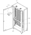
- FIG. 200 is a perspective view of the main device and the sub device shown in FIG. 199.
- FIG. 201 is a perspective view of the main apparatus shown in FIG. 200.
- FIG. 202 is a perspective view of the first storage part shown in FIG. 201.
- FIG. 203 is an enlarged perspective view of a part of the second storage part shown in FIG. 201.
- FIG. 204 is an enlarged perspective view of a portion of the second storage unit illustrated in FIG. 203.
- FIG. 205 is a perspective view of the medicine cartridge shown in FIG. 203.
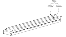
- FIG. 206 is a perspective view of a drug discharge part shown in FIG. 201.
- 207 is an enlarged view illustrating main parts of the drug discharge part shown in FIG.
- FIG. 208 is a perspective view of the recovery bin shown in FIG. 201.
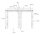
- FIG. 210 is another perspective view of the medicine cartridge and the cartridge mounting unit shown in FIG. 203.
- Figure 211 is a perspective view showing the internal configuration by opening the cover in the drug cartridge shown in FIG.
- FIG. 212 is a plan view illustrating an internal configuration by removing the inclined member and the cover in FIG. 211.
- FIG. 213 is an operational state diagram showing a state in which the drug cartridge shown in FIG. 212 is mounted on the cartridge mounting portion.
- FIG. 214 is an operating state diagram showing an operating state of the opening and closing block when the locking release member shown in FIG. 212 is coupled.
- FIG. 215 is an enlarged perspective view illustrating main parts of the cartridge mounting unit shown in FIG. 210.
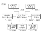
- 216 is a block diagram of a production management unit according to an embodiment of the present invention.
- 217 is a block diagram of a hospital management unit according to an embodiment of the present invention.
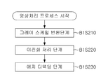
- 218 is a flowchart illustrating a step-by-step control method of the drug management system according to an embodiment of the present invention.
- connection does not necessarily mean a direct connection or a connection, but a concept including an indirect connection or connection through a medium.
- module or “unit” is a term used for convenience of description, it does not have a meaning or function distinguished from each other by itself.
- FIG. 1 is an environment diagram schematically illustrating an environment in which a drug dispensing system according to an embodiment of the present invention operates.
- the drug dispensing system 1 may communicate with various external electronic devices 2 and 3.
- a server (2, hereinafter referred to as a 'server') deployed in the hospital and / or staff of the hospital (e.g. doctors, pharmacists, nurses) Etc.
- an electronic device such as a PC assigned to a user, a smartphone, and / or a terminal (3, hereinafter, referred to as a “terminal”) for performing a similar function.
- a drug management system the environment in which the drug dispensing system according to an embodiment of the present invention operates may be referred to as a drug management system.
- the drug dispensing system 1 may be connected to the server 2 and / or the terminal 3 via a predetermined network N.
- the network N may include both wired and wireless networks.
- the server 2 may store various information about the patient, identification information and / or authentication information about the users, and the like.
- the various information about the patient may be human information such as the patient's name, gender, age, etc., medical history information such as the patient's disease history, prescription information about the medicine to be taken by the patient, and the like.
- the terminal 3 obtains necessary information by users connecting to the medication dispensing system 1 and / or the server 2 or performing input for operating the medication dispensing system 1 and / or the server 2. Can be used.
- FIGS 2 to 6 are diagrams for explaining various configurations of the drug delivery system according to an embodiment of the present invention.
- the drug dispensing system 1 may include various sub-devices.
- the various sub-devices may include at least one of the first drug dispensing device 100, the second drug dispensing device 200, and the drug collecting device 300.
- the first drug dispensing device 100 is a device that is relatively standardized and stores a drug having a relatively small volume, and can dispense the drug as necessary.
- the second drug dispensing device 200 is a relatively unstructured, relatively bulky drug, and / or a device used for medical practice.
- the drug dispensed through the second drug dispensing device 200 shall include not only a drug but also an apparatus used for medical practice.
- the drug collection device 300 may collect the drugs dispensed from the first drug delivery device 100 and the second drug delivery device 200, and deliver them to the user.
- first and second drug delivery devices 100 and 200 and the drug collection device 300 will be described later.
- the drug dispensing system 1 may be configured by various combinations of the sub devices 100, 200 and 300.
- the drug dispensing system 1 may be composed of one first drug dispensing device 100 and one drug collecting device 300.
- the drug dispensing system 1 may be composed of one second drug dispensing device 200 and one drug collecting device 300.
- one first drug dispensing device 100, one second drug dispensing device 200, and one drug collecting device 300 may be configured.
- a plurality of first drug dispensing devices 100 and one drug collecting device 300 may be configured.
- a plurality of second drug dispensing device 200 and one drug collecting device 300 may be configured.
- a combination of one first drug dispensing device 100, a plurality of second drug dispensing devices 200, and one drug collecting device 300, and a plurality of first drug dispensing devices 100 are provided.
- a combination of one second drug dispensing device 200 and one drug collecting device 300, a plurality of first drug dispensing devices 100, a plurality of second drug dispensing devices 200, and one drug collecting device In combination with 300, the drug dispensing system 1 may be configured.
- a plurality of drug collection device 300 may be configured in each combination.
- FIG. 7 is a block diagram for explaining a drug collection device according to an embodiment of the present invention
- Figure 8 is a schematic perspective view of the drug collection device according to an embodiment of the present invention.
- the drug collecting device 300 includes a communication unit 302, an output unit 310, an input unit 316, a storage unit 308, a control unit 318, and a drug inlet 320. It may include. Although the drug collecting device 300 is not specifically illustrated in the drawings, the drug collecting device 300 may include a drug collecting space inside the drug collecting device 300, and the drugs collected in the drug collecting space may be the drug collecting device 300. May be provided to the user via one side (eg, front face 300F). The drug inlet 320 is preferably located above the drug collection space.
- FIG. 8 illustrates that the drug inlet 320 is located on the right side of the drug collecting device 300, the drug inlet 320 may be located on the left side as needed. It can be located both on the left side.
- the communication unit 302 may communicate with other electronic devices, and may include a plurality of communication modules optimized for a plurality of communication protocols.
- the communication unit 302 may include an internet module unit, a short-range communication module unit, or the like that enables communication with the server 2 and / or the terminal 3 described above.
- the internet module unit 304 may refer to a module for accessing the Internet, and may be built in or external to the drug collection device 300.
- the short-range communication module unit 306 is a module for short-range communication, and the short-range communication technologies include Bluetooth, Radio Frequency Identification (RFID), Near Field Communication (NFC), Infrared Data Association (IrDa), and UWB. (Ultra Wideband), ZigBee and the like can be used.
- the communication unit 302 may further include another separate communication module for performing communication with the first and second drug delivery devices.
- the storage unit 308 may store information.
- the storage unit 308 may store information necessary for the operation of the drug collection device 300 and information generated by the operation of the drug collection device 300. In addition, the storage unit 308 may also store information necessary for the operation of the first and second drug delivery device (100,200) and information generated by their operation.
- the storage unit 308 may include various storage media.
- the storage unit 308 may be a flash memory, a random access memory (RAM), a static random access memory (SRAM), a read only memory (ROM), or an EEPROM.
- card type memory such as electrically erasable programmable read only memory, hard disk, magnetic memory, magnetic disk, optical disc such as CD or Blu-ray, SD card and
- the present invention may include at least one of other storage media that will be apparent to those skilled in the art.
- the storage unit 308 may be provided in a form mounted on the inside of the drug collection device 300, a form located separately to the outside, or a detachable form.
- the storage unit 308 having an external location may include not only an external hard disk but also a web storage that performs a storage function of the storage unit 308 on the Internet or the server 2. .
- the output unit 310 may output information.
- the user may receive various information through the output unit 310.
- the output unit 310 may output information using at least one of an audio signal and a visual signal.
- the output unit 310 may include at least one of a display, a speaker, and other output devices that are obvious to those skilled in the art.
- the output unit 310 may include at least one of an image output unit 312 and a sound output unit 314.
- the image output unit 312 may output a visual signal. That is, the image output unit 312 may display image information. For example, the image output unit 312 may display a user UI or a graphic user interface (GUI).
- GUI graphic user interface
- the image output unit 312 may include a liquid crystal display (LCD), a thin film transistor liquid crystal display, an organic light-emitting diode display, a flexible display, It may be implemented as at least one of a three-dimensional display (3D display) and other displays that are obvious to those skilled in the art.
- LCD liquid crystal display
- 3D display three-dimensional display
- the audio error output unit 314 may output an audio signal, that is, an audio signal.
- the sound output unit 314 may output sound signals related to various functions performed in the drug dispensing system 1.
- the sound output unit 314 may be implemented as a receiver, a speaker, a buzzer, or the like.
- the input unit 316 may receive an input required for the operation of the drug collecting device 300 and / or the drug dispensing device (100,200) from the user. The user may directly operate operations of the drug collection device 300 and / or the drug dispensing device 100 or 200 through the input unit 316.
- the input unit 316 may include a keypad, a dome switch, a jog wheel, a jog switch, a touch pad, and a common knowledge in the art. It may include at least one of the other input device that is obvious to the person having.
- the output unit 310 in particular, the image output unit 312 and the input unit 316 can be implemented integrally as a single device.
- the output unit 310 and the input unit 316 may be implemented as a touch screen which displays information and receives a touch input.
- the touch screen may include a display for displaying information and a touch panel for sensing a touch input.
- the touch panel detects a touch input and detects at least one of a location where the touch input is touched, an area touched, and an intensity of the touch.
- the touch screen may display information and receive a touch input.
- Drug inlet 320 may be a passage for receiving a drug from the drug delivery device (100,200).
- the controller 318 may control the overall operation of the drug dispensing system 1 including the drug collecting device 300 and / or the drug dispensing device 100, 200 and other components included therein. For example, the controller 318 may associate various pieces of information and process the information so that it can be used.
- the controller 318 may be implemented in a computer or similar device using software, hardware, or a combination thereof.
- the controller 318 may be hardware, including application specific integrated circuits (ASICs), digital signal processors (DSPs), digital signal processing devices (DSPDs), programmable logic devices (PLDs), field programmable gate arrays (FPGAs), and processors (processors). ), Controllers, micro-controllers, microprocessors, and at least one of an electrical device for performing a control function obvious to those skilled in the art. Can be.
- ASICs application specific integrated circuits
- DSPs digital signal processors
- DSPDs digital signal processing devices
- PLDs programmable logic devices
- FPGAs field programmable gate arrays
- processors processors
- the control unit 318 may be implemented by software code or software application written in one or more programming languages. Such software may be stored in the storage 308 and executed by a hardware configuration of the controller 318. The software may be installed by being transmitted from an external device, for example, the server 2 or the like, to the drug dispensing system 1.
- FIG. 9 is a schematic perspective view showing a first drug dispensing device according to the present invention.
- the first drug dispensing apparatus 100 includes a drug dispensing box D100 containing at least one drug, and the drug dispensing box D100 is the first drug dispensing apparatus 100.
- the first drug dispensing device 100 is a cartridge (D200) to be mounted on, the drug delivery drive means (D300) and the drug delivery drive means (D300) for discharging the drug contained in the drug delivery box (D100)
- Drug delivery drive means for moving the floor by layer (D400) may include.
- a plurality of drug dispensing boxes D100 may be mounted on a cartridge D200, and the cartridge D200 may be layered of the first drug dispensing apparatus 100. It may be provided as.
- At least one cartridge D200 may be installed in each layer of the first drug dispensing apparatus 100, and the number of drug dispensing boxes D100 that may be mounted on one cartridge D200 may be determined by those skilled in the art. Various changes can be made to suit the intention.
- the first drug dispensing apparatus 100 is to be dispensed by the drug dispensing driving means (D300) by rotating the dispensing unit (D110) of the drug dispensing box (D100) for receiving at least one drug
- the drug dispensing box D100 may be inserted and mounted to be detachably mounted on the cartridge D200.
- the drug dispensed to the outside by the drug delivery driving means (D300) may be seated on the drug delivery unit (D500).
- the drug delivery unit D500 may be, for example, a component including a conveyor belt. Hereinafter, for convenience of description, it may be referred to as a conveyor unit D500.
- the drug seated on the conveyor unit D500 may be collected in a predetermined external space by changing its position by belt rotational movement of the conveyor unit D500.
- the drug delivery unit D500 may transfer the dispensed medicine in a horizontal direction while the drug dispensing operation is performed.
- the speed at which the drug delivery unit D500 transfers the dispensed medicine in a horizontal direction may be constant or variable.
- the floor-by-floor movement of the drug delivery driving means D300 may be implemented by the drug delivery driving means moving part D400, and the drug delivery driving means moving part D400 may be an external signal (for example, the first medicine.
- the drug is a layer on which a drug delivery box (D100) containing a packaged medicine required by a control unit provided in the dispensing device 100 and / or a control signal generated by a control unit provided in the drug collecting device 300, etc.) is disposed.
- the dispensing driving means D300 may be moved.
- the drug dispensing driving means moving unit D400 may desire the drug dispensing driving means D300 by the signal. After moving to a layer, the packaging medicine required by the drug delivery box D100 may be dispensed by rotating the delivery unit D110 of the drug delivery box D100 by the drug delivery drive unit D300.
- the dispensing agent may be seated on the conveyor unit D500, and the conveyor unit D500 on which the medication is seated is moved to a position corresponding to a preset dispensing space by the drug dispensing driving unit moving unit D400.
- the drug seated by the belt rotational movement of the conveyor unit D500 may be collected in a predetermined external space.
- the first drug dispensing device 100 may be provided with a drug outlet at a position corresponding to the drug inlet 320 of the drug collection device 300 as described above, and dispensed from the drug dispensing box (D100).
- the drugs can be moved to the drug outlet and the drug inlet 320 by the drive of the conveyor (D500), the drug can be transferred to the drug collection space through the drug outlet and the drug inlet (320).
- the belt rotational movement of the conveyor unit D500 is not limited to that implemented after the conveyor unit D500 is moved to a position corresponding to a preset dispensing space, and the conveyor unit D500 is dispensing. It may be implemented before moving to a position corresponding to the space.
- the drug delivery drive means (D300) is drug delivery drive
- the moving unit (D400) can be dispensed from the drug delivery box (D100) sequentially or simultaneously with a plurality of drug delivery boxes placed on one floor located on the floor located, and when dispensing from any one floor is complete The drug may be dispensed again by moving to the floor.
- the conveyor unit (D500) is finally seated on the drug dispensing driving means moving unit (D400) By moving to a position corresponding to the predetermined dispensing space by a plurality of drugs seated by the belt rotational movement of the conveyor unit (D500) may be collected in a predetermined external space.
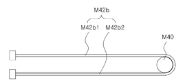
- 10 and 11 are schematic diagrams for explaining the principle that the drug is dispensed from the drug delivery box by the drug delivery drive means according to the present invention.
- the dispensing of the medication from the medication dispensing box D100 may be implemented by the rotation of the dispensing portion D110 exposed in front of the medication dispensing box D100, and the dispensing portion. Rotation of (D110) may be implemented to move the position of the drug delivery unit (U) of the drug delivery drive means (D300).
- the drug dispensing unit U may be one component constituting the drug dispensing driving means D300, and a plurality of drug dispensing units U may be set to implement one drug dispensing driving means D300. have.
- the drug delivery driving means (D300) may include at least two or more drug delivery unit (U).
- the drug dispensing driving unit D400 may move the drug dispensing driving unit D300 to a position corresponding to the drug dispensing box D100 in which the drug requiring dispensing is accommodated.
- the position shifting unit 10 (see FIG. 12) of the drug dispensing unit U3 (hereinafter referred to as the third drug dispensing unit) corresponding to the drug dispensing box D100 containing the drug requiring dispensing may be moved.
- the position moving unit D10 of the third drug dispensing unit U3 may be moved toward the drug dispensing box D100 according to an external signal, and eventually, the dispensing unit rotating unit D20 provided in the position moving unit D10. ) Is engaged with the discharge unit (D110).
- the dispensing part rotating part D20 is rotated, and the dispensing part D110 is also rotated by the dispensing part rotating part D20.
- the medicine contained in the drug delivery box (D100) by the rotation of the dispensing unit (D110) can be dispensed to the conveyor unit (D500) that is external, the drug seated on the conveyor unit (D500) is predetermined by the belt rotation movement It can be collected in the outer space of the.
- the position moving unit D10 to which the position is moved is not limited to the third drug dispensing unit U3, which will be described later with reference to FIGS. 20 to 25.
- FIGS. 12 and 13 are schematic perspective views showing a drug delivery unit according to an embodiment of the present invention
- Figure 14 is a schematic exploded perspective view showing a drug delivery unit according to an embodiment of the present invention
- Figure 15 is It is a schematic perspective view which shows the state where the position movement part of the drug delivery unit was moved according to one embodiment of the invention.
- 16 and 17 are schematic views showing a state in which the rotational support of the drug delivery unit is rotated according to an embodiment of the present invention.
- the drug dispensing unit U may be one component constituting the drug dispensing driving means D300, and the position of the drug dispensing unit U may be in contact with the dispensing part D110 of the drug dispensing box D100.
- a position moving unit (D10) having a dispensing unit rotating unit (D20) to be moved to rotate the dispensing unit (D110), a rotational power providing unit for generating a driving force for providing a rotational force to the dispensing unit rotating unit (D20) ( D30) and a position movement force providing unit D40 that provides a driving force for the position movement of the position movement unit.
- the rotational power providing unit (D30) and the positional movement power providing unit (D40) may be disposed adjacent to the position moving unit (D10), may be a kind of small motor for generating a rotational force.
- the position movement force providing unit (D40) may be driven by an external signal to generate a rotational force, the rotational force may rotate the pinion gear (D50).
- the position movement of the position moving unit D10 may be implemented by the rotation of the pinion gear D50.
- the position shifting unit D10 linearly moves by the rotation of the pinion gear D50 so that the dispensing unit rotating unit D20 comes into contact with the dispensing unit D110 of the medicine dispensing box D100.
- the rack gear (D11) may be a kind of linear gear.
- the rack gear D11 may be formed on the bottom surface of the position shifting unit D10, and the rack gear D11 may be linearly moved by the rotation of the pinion gear D50 to move the position shifting unit D10. have.
- the rotation of the pinion gear (D50) may be implemented by a worm gear (D60), the worm gear may include a worm (D62) and a worm wheel (D64).
- the position movement force providing unit D40 may include a worm gear D60 and a pinion gear D50, and the rotation direction is changed by a worm gear D60 including a worm D62 and a worm wheel D64. This can be
- the rotation direction of the wheel 62 and the rotation direction of the worm wheel D64 are different from each other, and the worm wheel D64 may be rotated in cooperation with each other in the same direction as the rotation direction of the pinion gear D50. This is because the axis of rotation is shared.
- Rotation of the pinion gear (D50) may be a linear movement of the rack gear (D11) of the position moving part (D10), the dispensing part rotating part (D20) by the linear movement of the position moving part (D10) drug delivery box (D100) ) May be in contact with the discharge unit (D110).
- the position moving unit (D10) is connected to the rack gear unit (D12) and the rack gear unit (D12) in which the above-mentioned rack gear (D11) is formed and rotatably supporting the dispensing unit rotating unit (D20). It may include a rotation support (D14).
- the rotation support part D14 may be connected to the rack gear part D12 so as to be rotatable, thereby improving transmission of the rotational driving force by contact from the discharge part rotating part D20 to the discharge part D110. have.
- the dispensing part rotating part D20 and the dispensing part D110 may be formed of a kind of gear, and the dispensing part D110 may be formed by the rotation of the dispensing part rotating part D20. To be rotated they must be engaged with each other.
- the teeth of the gear of the dispensing unit rotating unit D20 and the gears of the dispensing unit D110 are mutually different. There is a possibility of a bump.
- the dispensing part rotating part D20 should be engaged with each other through vertical movement, and in the present invention, the rotating support part D14 may be implemented by rotating from the rack gear part D12.
- the rotation of the rotation support portion (D14) from the rack gear portion (D12) can be implemented within a limited range by the restoring member (D70) provided on the rotation shaft, the dispensing portion rotating portion (D20) Rotation generated in the process of engaging with the dispensing unit (D110) is disengaged after the dispensing unit rotating part (D20) rotates the dispensing unit (D110) to dispense the medicament in place by the restoring member (D70) Can be returned.
- Rotation of the discharge portion rotating unit (D20) may be implemented by a rotational power providing unit (D30) disposed adjacent to the position moving unit (D10), the driving force of the rotational power providing unit (D30) is a rotational power linking unit ( D32) may be delivered to the dispensing part rotating unit (D20).
- the rotary power linkage unit D32 is a component of the rotary support unit D14, and may be a kind of gear, and the rotational power of the rotary power linkage unit D32 may be discharged by the rotary power transfer unit D34. D20).
- the rotary power transmission unit D34 may be a component of the rotary support unit D14 disposed to be in contact with the rotary power interlocking unit D32, and the rotational force of the rotary power interlocking unit D32 may be disbursed by a kind of gear. It can be transmitted to the sub-rotation unit (D20).
- the rotational power transmission unit D34 is a first rotational power transmission unit D34a and the first rotational power transmission unit D34a and the discharge unit rotation unit D20 which are disposed to contact the rotational power interlocking unit D32. It may include a second rotary power transmission unit (D34b) disposed in contact with.
- the rotary power interlocking unit D32, the rotary power transmitting unit D34, and the discharge unit rotating unit D20 are disposed to engage with each other so that the rotary power of the rotary power providing unit D30 is finally the discharge unit rotating unit ( D20).
- the rotational power of the rotational power providing unit D30 is not limited to being transmitted to the discharge unit rotating unit D20 by the plurality of gears as described above, and the rotational power providing unit D30 directly discharges the rotating unit.
- the rotation D20 may be rotated, and the rotation power linking unit D32 may be arranged to engage the discharge unit rotation unit D20 without the rotation power transmission unit D34.
- rotational power linking unit (D32), the rotational power transmission unit (D34) and the discharge portion rotating unit (D20) is not limited to being formed of a gear, it can be understood that it can also be implemented by a belt or a chain.
- the position movement of the position movement unit (D10) by the position movement force providing unit (D40) can be supported by the position movement support (D80), the position movement support (D80) of the position movement unit (D10) It can be arranged in both directions.
- the position movement support part D80 may be a kind of fixed structure that supports the movement of the position movement part D10 in view of the position movement part D10, and includes a position fixing part D82 and at least one support shaft D84. It may include.
- the position fixing part D82 may be a kind of separation preventing wall that prevents the moving of the position moving part D10, and the support shaft D84 may be a connecting shaft connecting the position fixing part D82 to each other.
- the position moving part (D10) may be provided with a through portion (S) for allowing the support shaft (D84) to be penetrated so that the support shaft (D84) is disposed between the position fixing portion (D82),
- the penetrating portion S may be continuously formed along the position movement direction of the position movement portion D10.
- the through part S may define a range of position movement of the position moving part D10, and the position moving part D10 may have a medicine dispensing box while the support shaft D84 penetrates the through part S. D100).
- the movement of the position moving part D10 may be guided by a guide part D86 coupled to the support shaft D84, and the guide part D86 is in contact with a wall defining the through part S. It may be one component of the position movement support (D80) to guide the position movement of the position movement unit (D10).
- the position moving part D10 may slide while being in contact with the guide part D86, but the guide part D86 may be formed as a ball bearing to guide the position movement by the rotation of the ball bearing.
- the drug dispensing unit (U) can detect whether the position movement of the position moving unit (D10) by the movement detection unit (D90), the movement detection unit (D90)
- the position moving part D10 may be disposed in one direction.
- the movement detection unit (D90) may detect the movement of the extension (D95) of the position moving unit (D10) extending toward the movement detection unit (D90), the position movement unit (D10) Is formed in at least two or more within the movement range of can detect whether the extension (D95), that is, the movement of the position moving unit (D10).
- Figure 19 is a schematic perspective view showing a state in which the position moving portion of the drug dispensing unit according to another embodiment of the present invention is moved to be.
- FIG. 18 is a drug delivery unit (U ') according to another embodiment of the present invention is a rotary power linkage (D32'), the rotational power transmission unit (D34 ') and the discharge portion rotating unit Except for the arrangement relationship of (D20 '), since the configuration and effect are the same as the drug delivery unit (U) according to an embodiment of the present invention described with reference to FIGS. 12 to 17, the rotary power linkage (D32') The descriptions other than the arrangement relationship between the rotational power transmission unit D34 'and the discharge unit rotating unit D20' will be omitted.
- the rotational power transmission unit D34 ' may include a first rotational power transmission unit D34'a and a second rotational power transmission unit D34'b, and a rotational power interlocking unit D32b and the first rotational unit.
- the power transmission unit D34'a, the second rotational power transmission unit D34'b, and the dispensing unit rotating unit 20 ' may be entirely disposed as "a".
- Figure 21 is a schematic perspective view showing an operating state of the drug delivery drive means according to the present invention.
- FIG. 22 is a schematic perspective view showing another operating state of the drug delivery driving means according to the present invention.
- the drug dispensing driving means D300 may be mounted on the first drug dispensing apparatus 100 having at least one layer and a plurality of drug dispensing boxes D100 mounted on the layers. And, it may be a kind of drug delivery structure for dispensing at least one or more drugs by rotating the delivery unit (D110) of the drug delivery box (D100).
- the drug dispensing driving means (D300) may include a first drug dispensing unit to the N-th drug dispensing unit disposed to correspond to the drug dispensing box mounted on one of the layers, the first drug dispensing unit The unit to the N-th drug dispensing unit may rotate the dispensing unit D110 of the drug dispensing box D100 containing the drug requiring dispensing so as to dispensing the drug requiring dispensing (N is a natural number).
- the first drug dispensing unit to the N-th drug dispensing unit dispenses respective drugs from the plurality of drug dispensing boxes D100 requiring dispensing.
- the dispensing units D110 of the plurality of drug dispensing boxes D100 may be rotated simultaneously or sequentially.
- the number of drug dispensing units (U) provided in the drug dispensing driving means (D500) is less than the number of drug dispensing boxes (D500) for dispensing the drug in one layer (for example, If the number of drug delivery boxes (D500) to dispense the drug to the floor is three, the number of drug delivery units (U) provided in the drug delivery drive means (D500) two, drug delivery box (D500)
- the drug can be dispensed sequentially while moving the position of the drug dispensing drive unit (U) from side to side so that the drug can be dispensed in accordance with the drug dispensing order given to).
- the drug dispensing driving means (D300) according to the present invention can be accurately dispensed from the drug dispensing box (D100) necessary drugs according to the prescription of the patient and at the same time can improve the efficiency of drug dispensing.
- first drug dispensing unit to the N-th drug dispensing unit may be disposed at the same height to form a first drug dispensing unit layer A, and the remainder is the first drug dispensing unit layer A. It may be disposed at the same height in one direction of the second drug delivery unit layer (B).
- the dispensing part rotating part of the drug dispensing unit constituting the second drug dispensing unit layer B may have the same height as that of the dispensing part rotating part of the drug dispensing unit constituting the first drug dispensing unit layer A.
- the first drug dispensing unit layer A and the second drug dispensing unit layer B disposed to have different heights are intended to correspond to the widths of the various drug dispensing boxes D100 and have a relatively large width.
- a drug dispensing unit constituting the first drug dispensing unit layer A and a drug dispensing unit constituting the second drug dispensing unit layer B may be applied simultaneously. .
- the drug when dispensing a drug from the drug dispensing box (D100) having a relatively small width, the drug can be dispensed with only the drug dispensing unit constituting the first drug dispensing unit layer (A).
- the corresponding drug dispensing unit when the drug dispensing box D100 is relatively small may be a drug dispensing unit included in the first drug dispensing unit layer A.
- N 12 and the drug dispensing box D100 is relatively small will be described as an example.
- the third drug dispensing unit U3 and the sixth drug dispensing unit are dispensed by the drug dispensing driving unit D300 according to the present invention.
- the operation state will be described taking as an example a case where a medicine contained in the medicine dispensing box D100 corresponding to the unit U6 is dispensed.
- the drug dispensing driving means D300 may move the drug dispensing driving means D300 to a position corresponding to a drug dispensing box D100 in which a drug requiring dispensing is accommodated.
- the position movement force providing unit D40 of the third drug delivery unit U3 and the sixth drug delivery unit U6 may be driven by an external signal.
- the position shifting unit D10 of the sixth drug dispensing unit U6 may be moved to a corresponding drug dispensing box D100, and each dispensing unit rotating unit D20 is a dispensing unit D110 of the drug dispensing box D100. ) Can be engaged.
- the rotational power providing unit D30 of the third drug delivery unit U3 and the rotational power providing unit D30 of the sixth drug delivery unit U6 generate a driving force to each of the discharge unit rotation units D20. It is rotated, thereby the dispensing unit (D110) of the corresponding drug dispensing box (D100) can be rotated to be dispensed to the conveyor unit (D500).
- the driving of the rotational power providing unit D30 that generates the driving force need not be limited to the third drug delivery unit U3 and the sixth drug delivery unit U6.
- Rotational power providing unit D30 of the drug delivery unit U1, U2, U4, U5, U7 to U12 other than the drug delivery unit U3 and the sixth drug delivery unit U6 may be driven. Do.
- the rotational power providing unit D30 of the third drug delivery unit U3 and the rotational power providing unit D30 of the sixth drug delivery unit U6 stop the rotation to drive the driving force.
- the position shifting unit D10 may be returned to its original position by the driving force of the position movement force providing unit D40 of the third drug dispensing unit U3 and the sixth drug dispensing unit U6. have.
- the position movement direction of the drug delivery unit (U3, U6) by the position movement force providing unit D40 may be implemented by switching the rotation direction of the position movement force providing unit (D40).
- the corresponding moving parts D10 may be simultaneously moved by the driving force of the corresponding rotating power providing unit D30, respectively.
- the movement of the position moving unit D10 and the generation of the driving force of the rotational power providing unit D30 are not limited to being implemented at the same time, and may be implemented sequentially.
- Figure 23 is a schematic perspective view showing another operating state of the drug delivery drive means according to the present invention.
- the drug dispensing driving unit D400 may move the drug dispensing driving unit D300 to a position corresponding to a drug dispensing box D100 in which a drug requiring dispensing is accommodated.
- the completion is completed, not only the position movement force providing unit D40 of the third drug dispensing unit U3 and the sixth drug dispensing unit U6 by the external signal, but also the third drug dispensing unit U3 and the sixth drug dispensing unit.
- the position movement force providing unit D40 of at least one of the drug dispensing units U1, U2, U4, U5, U7 to U12 other than the unit U6 may also be driven.
- the position shifting unit D10 of the drug dispensing unit U9 may be moved to a corresponding drug dispensing box D100, respectively, and each dispensing unit rotating unit D20 may be dispensing unit D110 and the drug dispensing box D100. Can interlock.
- the rotational power providing unit D30 of the third drug delivery unit U3 and the rotational power providing unit D30 of the sixth drug delivery unit U6 generate a driving force to each of the discharge unit rotation units D20. It is rotated, thereby the dispensing unit (D110) of the corresponding drug dispensing box (D100) can be rotated to be dispensed to the conveyor unit (D500).
- dispensing part rotating parts D20 whose positions are moved are engaged with corresponding dispensing parts D110, respectively, but the dispensing part rotating parts D20 rotated are the third drug dispensing unit U3 and the sixth drug dispensing unit U6. ), So that the dispensing part (D110) rotated may also be limited thereto.
- each position shifting unit D10 may be returned to its original position by a driving force of the position moving force providing unit D40 of the first drug dispensing unit U1 to the ninth drug dispensing unit U9. have.
- each of the rotational power providing unit (D30) of the third drug delivery unit (U3) and the sixth drug delivery unit (U6) is not limited to implementing at the same time, may be implemented sequentially. .
- FIG. 24 is a schematic perspective view for explaining that the drug dispensing driving means according to the present invention is applicable to a drug dispensing box of various sizes
- FIG. 25 is a schematic perspective view showing an operating state in the case of FIG.
- the drug dispensing driving means D300 may include a first drug dispensing unit layer A and a second drug dispensing unit layer B, and the second drug dispensing unit layer (B).
- the dispensing part rotating part of the drug dispensing unit constituting B) may have the same height as the dispensing part rotating part of the drug dispensing unit constituting the first drug dispensing unit layer (A).
- the corresponding drug dispensing unit in the case where the drug dispensing box D100 is relatively large is included in both the first drug dispensing unit layer A and the second drug dispensing unit layer B. Can be.
- the drug dispensing unit corresponding to the relatively large drug dispensing box D100 may include a first drug dispensing unit U1, a tenth drug dispensing unit U10, a fourth drug dispensing unit U4, and an eleventh drug dispensing unit D100.
- the drug dispensing unit U11, the seventh drug dispensing unit U7, and the twelfth drug dispensing unit U12 may be provided.
- the drug dispensing driving means D300 according to the present invention may be applicable to both the drug dispensing box D100 having various widths by the first drug dispensing unit layer U1 and the second drug dispensing unit layer U2. have.
- the process of dispensing a drug from the drug dispensing box D100 may be the same as described with reference to FIGS. 20 to 23.
- FIGS. 26 and 27 A drug delivery unit according to an embodiment will be described with reference to FIGS. 26 and 27.
- 26 is a perspective view illustrating a partially cut-out of the drug delivery unit according to an embodiment
- FIG. 27 is a perspective view illustrating a drug delivery unit according to an embodiment.
- the drug delivery unit D500 or the conveyor unit is a component in which a drug to be dispensed is seated.
- the drug delivery part D500 includes a conveyor belt CB11, a pair of track shafts CB12a and CB12b, a pair of path change rolls CB13a and CB13b, and a drive roll CB14.
- the conveyor belt CB11 rotates along the caterpillar.
- Conveyor belt CB11 is mounted with the drug dispensed.
- the pair of track axes CB12a and CB12b are in charge of both axes of the endless track on which the conveyor belt CB11 rotates. That is, the conveyor belt CB11 rotates along the track via the outer circumferential surfaces of the pair of track shafts CB12a and CB12b.
- the conveyor belt CB11 may rotate via a pair of path change rolls CB13a and CB13b and a driving roll CB14.
- the driving roll CB14 is connected to the motor CB15 and the timing belt CB16 and rotates to transmit the driving force so that the conveyor belt CB11 can rotate.
- the pair of path switching rolls CB13a and CB13b are provided to contact the outer circumferential surface of the conveyor belt CB11, and the driving roll CB14 is provided to contact the inner circumferential surface of the conveyor belt CB11.
- the driving roll CB14 is located between the pair of path switching rolls CB13a and CB13b, and at the same time a lower position than the pair of path switching rolls CB13a and CB13b, that is, a pair based on the conveyor belt CB11.
- a support plate CB171 is provided at the lower end of the upper surface of the conveyor belt CB11.
- Support plate (CB171) supports the upper surface of the conveyor belt (CB11) and receives a shock to the drug that falls when the drug is discharged through the upper surface of the conveyor belt (CB11).
- drug delivery unit (D500) includes a side member (CB172). The above-mentioned support plate CB171 is fixed to the side member CB172.
- FIG. 28 is a perspective view illustrating a drug delivery unit having a side guard unit according to an embodiment
- FIG. 29 is a side view illustrating a drug delivery unit of FIG. 28.
- Side of the drug delivery unit according to the present embodiment is provided with a predetermined height as shown in Figure 28 is provided with at least one or more side guard portion (CB30) to prevent the drug from leaving the outside when the drug is seated Can be.
- CB30 side guard portion
- the side guard part CB30 may include a fixing part CB33, first inclined parts CB32a and CB32b, and a height reinforcing part CB31.
- the fixing part CB33 is a component for fixing the side guard parts CB30a and CB30b to the side member CB172.
- the first inclined portions CB32a and CB32b are formed to be inclined upward toward the outside.
- the first inclined portions CB32a and CB32b have a function of enlarging a region in which the dispensing agent may be seated, and minimize the drop impact due to the inclination of the medication.
- the height reinforcement part CB31 functions to secure the height of the side guard part CB30 to prevent the drug from being bounced up by a bounce while leaving the drug.
- FIG. 30 is a perspective view illustrating a drug delivery unit provided with a side guard unit according to another embodiment
- FIG. 31 is a side view illustrating a drug delivery unit of FIG. 30.
- the side guard part CB30 may be provided with a shock absorbing member CB35 that absorbs the shock generated by the blowing of the drug.
- the shock absorbing member CB35 is formed of a material capable of absorbing shock inside the side guard parts CB30a and CB30b.
- FIG. 32 is a perspective view illustrating a drug delivery unit provided with a side guard unit according to still another embodiment
- FIG. 33 is a side view illustrating a drug delivery unit of FIG. 32.
- the side guard portion CB30a ′ opposite to the direction CBD1 in which the drug delivery box D100 is located is opposite to the first slopes CB32a and CB32b.
- the second inclined portion CB34 may be included.
- the second inclined portion CB34 may be formed to be inclined inward to more actively prevent the drug that is dropped upon delivery from being bounced outward.
- FIGS. 34 to 36 are perspective views illustrating a cartridge according to one embodiment
- FIGS. 35 and 36 are perspective views illustrating a configuration and an operation of a fixing unit according to an embodiment.
- the cartridge D200 includes a cartridge housing composed of a lower housing CR40 and a rear housing CR50.
- the lower housing CR40 supports the drug dispensing box when the drug dispensing box to be connected to be described later is entered, and the rear housing CR50 restricts the drug dispensing box from entering a predetermined distance or more.
- a rail CR41 is provided at an upper end of the lower housing CR40 along the entry path of the drug delivery box D100 to be described later.
- the rail CR41 guides the medicine dispensing box D100 to enter for connection along the entry path.
- the rail CR41 is formed to have a predetermined length and is formed in an upwardly protruding shape. In addition, the rail CR41 may be formed in two or more protruding shapes parallel to each other.
- the first housing transmitting and receiving terminal CR51 may be provided in the rear housing CR50.
- the first data transmission and reception terminal CR51 is connected to the drug delivery box to transmit and receive data with the control means in the drug delivery box.
- the drug dispensing apparatus may receive the UUID of the drug dispensing box through the first data transmission / reception terminal CR51 and may acquire information such as the type and quantity of drugs stored in the dispensing box.
- the first data transmission and reception terminal CR51 is formed in a protruding shape having a predetermined step toward the front from the rear housing CR50, and a plurality of connector pins for electrically connecting the drug delivery box at the bottom It is provided.
- the lower housing CR40 includes a separation promoting part CR42.
- the separation promoting unit CR42 applies a force in the separation direction to the drug delivery box D100 at the time of separation of the drug delivery box to be described later.
- the separation promoting part CR42 includes a first protrusion part CR421 and a first elastic member CR422.
- the first protrusion CR421 protrudes to an upper end of the lower housing CR40 and is exposed to the outside.
- the first elastic member CR422 is pressurized in the process of connecting the drug delivery box D100 and provides a restoring force by the elastic force to the drug delivery box D100 when the drug delivery box D100 is separated.
- the rear housing (CR50) is provided with a locking portion (CR52) for fixing to release or detachable drug delivery box (D100).
- the locking unit CR52 includes a cam CR523, a locking unit body CR522, a hook unit CR521, an extension unit CR524, a sensing unit CR525, and a sensing unit CR526. Include.
- the cam CR523 rotates about a certain axis, and has a long radius and a short radius about an axis that is the center of rotation.
- the locking unit body CR522 constitutes a body of the locking unit. As shown in FIGS. 35 and 36, the locking unit body CR522 is provided to be in contact with the outer circumferential surface of the cam CR523. As the cam CR523 rotates, the locking unit body CR522 is raised. When it comes in contact with the short radius, it operates to descend.
- the hook portion CR521 extends from the front surface of the lock portion main body CR522 and rises or falls together as the lock portion main body CR522 moves up and down.
- the detector CR526 may further include an extension part CR524 extending upwardly from an upper end of the lock part body CR522, and adjacent to the extension part CR524.
- a sensor including a light receiver and a light emitter may be used, for example, an infrared sensor.
- the sensing unit CR525 is formed by extending from one side of the extension unit CR524, and the sensing unit CR525 is provided to ascend and descend between the light receiving unit and the light emitting unit of the sensing unit CR526. Is determined as to whether the locking portion CR52 is in the fixed position or the release position.
- FIGS. 37 to 39 A drug delivery box according to an embodiment will be described with reference to FIGS. 37 to 39.
- 37 is a perspective view showing the state of the drug delivery box according to an embodiment
- Figure 38 is a front side bottom perspective view showing the state of the drug delivery box of Figure 37
- Figure 39 is a view of the drug delivery box of Figure 37 Rear side bottom perspective view.
- the drug delivery box D100 includes a delivery box housing CR61.
- the housing CR61 includes a housing body CR611 and a front end portion CR612.
- a discharge port CR613 is formed in the front end portion CR612, and the gear CR621 is provided to the outside.
- the gear CR621 may be the same component as the dispensing unit D110 (see FIGS. 16 and 17) of the drug dispensing box D100 described above.
- a rail accommodating portion CR64 is formed at a bottom of the housing main body CR611.
- the rail accommodating portion CR64 is inserted along the rail and guided along the entry path.
- the rail accommodating part CR64 is formed up to the rear surface of the housing main body CR611.
- the rail accommodating portion CR64 is accommodated by the rail from the rear side when the drug delivery box and the cartridge is connected, and the rail is gradually received toward the front side along the rail accommodating portion CR64.
- the rail accommodating portion CR64 may have an accommodating start portion CR64a formed on the rear side of the dispensing box housing CR611.
- the accommodating start part CR64a is formed as a part of the rail accommodating part CR64 so that the width may gradually increase toward the rear side.
- the accommodating start part CR64a is a starting point for accommodating the rail, so that the width thereof is expanded so that the rail can be accommodated more easily.
- the accommodation initiator CR64a may be formed in various lengths. That is, it is also possible to form such that the entire width of the rail receiving portion CR64 gradually increases toward the rear side.
- a separation promoting part accommodating groove CR65 is formed which accommodates the above-mentioned separation promoting part.
- the separation promoting part is pressed in the state accommodated in the receiving groove CR65 or the force applied by the elastic force in the separation direction to the housing body CR611 when the drug delivery box and the cartridge are connected.
- the rear surface of the housing body CR611 may include data terminal portions CR66 and CR67.
- the data terminal portion includes a terminal accommodating groove CR66 and a second data transmitting and receiving terminal CR67.
- the terminal accommodating groove CR66 accommodates a data transmission / reception terminal of the cartridge, and the second data transmission / reception terminal CR67 is electrically connected to the data transmission / reception terminal of the cartridge.
- a locking portion CR68 is formed on the rear surface of the housing main body CR611.
- the locking portion CR68 is formed in a stepped groove shape so that the hook portion of the lock portion of the cartridge described above can be caught.
- FIG. 40 is a bottom perspective view of the rear side of the drug dispensing box of FIG. 37 viewed from another angle
- FIGS. 41 to 43 are cutaway perspective views showing a state of the drug dispensing box of FIG. 37.
- the rotating part CR691 is exposed at the front side of the rail accommodating part CR64 formed in the bottom face of the housing main body CR611.
- the rotating unit CR691 is a component that is pressed by the rail when the rail described above is accommodated as one component of the power interruption unit.
- the drug delivery box D100 includes at least one gear that receives power from the outside.
- the power interrupter is a mechanical component that controls the gears to restrain or release, despite the power transmitted from the outside.
- the power interruption unit includes a rotating unit CR691 and a breaking unit main body CR692.
- the rotation part CR691 includes a first end CR6911, a rotation shaft CR6912, and a second end CR6913.
- the first end CR6911 rotates about the rotation shaft CR6912
- the second end CR6913 is provided on the other side of the first end CR6911 with respect to the rotation shaft CR6912 to provide the first end CR6911. It rotates in the same direction as the rotation direction of.
- the blocking unit body CR692 includes a contact portion CR6921, a first extension portion CR6922, a second extension portion CR6923, and a second protrusion portion CR6924.
- the contact portion CR6921 is provided in contact with the second end CR6913 described above.
- the first extension portion CR6922 extends from the contact portion CR6921 in the direction of the gear CR622, and the second extension portion CR6923 extends upward from the gear CR622 side end portion of the first extension portion CR6922. do.
- a second protrusion CR6924 protruding in the direction of the gear CR622 is formed.
- the second protrusion CR6924 is inserted between the tooth and the tooth of the gear CR622 to restrain the rotation of the gear CR622, or between the tooth and the tooth of the gear CR622. Departing from, the gear CR622 is released to be rotatable.
- the second elastic member CR693 may be provided to contact the second extension part CR6923.
- the second elastic member CR693 functions to push the second extension part CR6923 in the direction in which the gear CR622 is provided by elasticity.
- FIGS. 45 and 46 are schematic views schematically illustrating a connection state of a drug delivery box and a cartridge according to one embodiment.
- the drug delivery box D100 enters along the rail CR41 provided in the bottom housing CR40 of the cartridge D200 and is coupled to the cartridge D200.
- the separation promoting unit CR42, the first transmission / reception terminal CR51, and the locking unit CR52 provided in the cartridge D200 are inserted into corresponding components of the drug delivery box D100, respectively.
- the rail (CR41) is accommodated in the rail receiving portion (CR64), the hook portion (521) is inserted into the locking portion (CR68) formed on the back of the drug delivery box (D100) Is fixed in such a way as to hang.
- the first data transmission / reception terminal CR51 is electrically connected to the drug delivery box D100 in a state accommodated in the data terminal unit CR66. At this time, the short radius portion of the outer surface of the cam CR523 is in contact with the locking portion main body CR522.
- the long radius portion of the outer peripheral surface of the cam (CR523) is in contact with the locking portion (CR522) and the hook portion (521) is lifted.
- the hook portion CR521 is lifted up, the hook portion CR521 is released from the hook portion CR68 formed on the rear surface of the drug delivery box D100, so that the drug delivery box D100 is detachable.
- the rail (CR41) is gradually separated from the rail receiving groove (CR64) is increased, the first data transmission and reception terminal (CR51) is the data terminal portion (CR66) and the data terminal portion ( CR66).
- the drug delivery drive BOX1, the blaster package drug delivery box BOX2, the ampule type drug delivery box BOX3, and the pouch type drug delivery box BOX4, which will be described below, are drug delivery drive. It may be provided with both the structure of the dispensing unit (D110) for dispensing the drug by the driving of the means (D300) and the coupling structure for coupling to the cartridge (D200). However, hereinafter, detailed description thereof will be omitted for convenience of description.
- Drug delivery box is a device for dispensing the drug is stored therein in the form of a package.
- Medicine drug delivery device includes a storage unit, the transfer unit, the cutting unit, the light source unit and the scan unit.
- FIGS. 47 and 48 A housing constituting the outline will be described with reference to FIGS. 47 and 48.
- 47 is a perspective view showing the state of the medicine-type drug delivery box according to an embodiment of the present invention
- Figure 48 is a bottom perspective view showing the state of the medicine-type drug delivery box according to an embodiment.
- the housing constituting the outline of the drug delivery type medication delivery box BOX1 includes a housing main body B1130, a front portion B1110, and a housing cover B1120.
- the housing body B1130 is formed in a rectangular parallelepiped shape as a whole.
- a housing cover B1120 is provided at an upper end of the housing body B1130.
- the housing cover B1120 is fixed at one side to be rotatable and can be opened and closed.
- the front part B1110 is formed with an outlet B1112 through which the cut medicine is discharged.
- the outlet B1112 is provided to penetrate through the front end cover B1111 to be exposed to the outside.
- the discharge port (B1112) may be provided with a sensor (not shown) for detecting the discharge medicine. In this case, the number of discharged medicines may be counted by providing a counting means for counting the number of discharged medicines detected by the sensor.
- a rail receiving portion B1140 is provided at the lower end of the housing body B1130.
- the rail accommodating part B1140 receives the rail formed in the cartridge D200 in which the medicine-type drug dispensing box BOX1 according to the present embodiment is accommodated, and functions to guide the insertion.
- FIG. 49 is an exploded perspective view of a partially cut medicine-type drug delivery box according to an embodiment.
- the front end B1110 of the housing includes a front end body B1115 and a front end cover B1111.
- the front end body B1115 is formed with a first medicine moving device B1116 connected to communicate with the outlet B1112 described above.
- the front end body B1115 has a cutout B1200 therein.
- the cutting part B1200 is formed with a second medicine drug moving tool B1210, and cuts the medicine drug package moving through the second medicine drug moving tool B1210.
- the second medicine drug moving device B1210 is communicatively connected to the first medicine drug moving device B1116 of the front end body B1115 and the outlet B1112 of the front end cover B1111.
- FIGS. 50 and 51 are cross-sectional views showing a state of the medicine-type drug delivery box according to an embodiment
- Figure 51 is a cutaway perspective view of a portion of the medicine-type drug delivery box according to an embodiment cut.
- the storage part B1300 is formed in a wheel shape and is stored in a state in which the medicine package B12 is wound.
- the storage part B1300 includes a core B1320 and a side case B1310.
- the medicine package B12 is wound around the core B1320 and then unrolled by the transfer unit B1400.
- the side case B1310 functions to prevent the side package from being separated to the side when the medicine package B12 is wound or unwound on the core B1320.
- the storage unit (B1300) can also be formed simply by the space portion that can be stored in the medicine package. In other words, it is also possible to form a simple space without a component such as a wheel in the storage portion, and to simply fold the medicine package to the formed space portion.
- the transfer part B1400 includes a pair of first rolls B1410, a pair of second rolls B1420, and a discharge roll B1430.
- the pair of first rolls B1410 includes a first upper roll B1411 and a first lower roll B1412.
- the first upper roll B1411 is positioned above the first lower roll B1412 and provided to contact the first lower roll B1412.
- the outer circumferential surfaces of the first upper roll B1411 and the first lower roll B1412 may be formed of an elastic material, particularly a porous material. Since the outer circumferential surfaces of the first upper roll B1411 and the first lower roll B1412 are formed of an elastic material, a force for pressing the drugs in the medicine package interposed therebetween can be minimized.
- the first lower roll B1412 in this embodiment is driven by a motor, preferably a stepper motor, and the first upper roll B1411 is passively rotated in accordance with the rotational direction of the first lower roll B1412.
- the pair of first rolls B1410 guide the medicine package B12 to be discharged toward the discharge roll B1430 in a state where the front end of the medicine package B12 is first positioned.
- the pair of second rolls B1420 transfers the front end portion of the medicine package B12 transferred from the pair of first rolls B1410 to the discharge roll B1430.
- the pair of second rolls B1420 includes a second upper roll B1421 and a second lower roll B1422.
- the second upper roll B1421 is positioned above the second lower roll B1422 and provided to contact the second lower roll B1422.
- the outer circumferential surfaces of the second upper roll B1421 and the second lower roll B1422 may be formed of an elastic material, particularly a porous material. Since the outer circumferential surfaces of the second upper roll B1421 and the second lower roll B1422 are formed of an elastic material, a force for pressing the drugs in the medicine package interposed therebetween can be minimized.
- the second lower roll B1422 in this embodiment is driven by a motor, preferably a stepper motor, and the second upper roll B1421 rotates passively in accordance with the rotational direction of the second lower roll B1422.
- the pair of second rolls B1420 transfers the foremost end of the medicine package B12 toward the discharge roll B1430.
- the first lower roll B1412 and the second lower roll B1422 are driven by independent driving motors, respectively.
- the medicine package B12 interposed between the first lower roll B1412 and the second lower roll B1422 is folded or loosened, detection of a cut line of the medicine package B12 may not be easy.
- by driving one of the first lower roll (B1412) and the second lower roll (B1422) in the direction of generating tension in the medicine package (B12) it can minimize the error that may occur when the detection of the cut line. At this time, it is possible to apply an accurate tension by driving the respective rolls using a step motor.
- the first upper roll (B1411) and the second upper roll (B1421) is connected to the upper by an elastic member (B1403).
- the first upper roll B1411 and the second upper roll B1421 are fixed by the elastic member B1403 to have a constant operating range in the vertical direction, and are lifted by the user during initial setting of the medicine package B12 or when an error occurs. Even if the medicine package B12 is transported in a state interposed between the first roll B1410 and the second roll B1420, the force applied to the medicine contained in the medicine package B12 is minimized. .
- a discharging roll B1430 may be provided at the distal end portion of the conveying direction.
- the discharge roll B1430 discharges the medicine package B12 transferred from the pair of second rolls B1420 to the outside.
- the discharge roll B1430 receives the driving force using the second upper roll B1421 and the timing belt.
- a support part B1150 for supporting the medicine package to be transported via the first lower roll B1412 and the second lower roll B1422 is included.
- the medicine package is conveyed in a supported state by a transfer plate B1151 formed in a flat plate shape on an upper end of the support part B1150.
- the first lower roll (B1412) and the second lower roll (B1422) is provided in a state exposed on the transfer plate (B1151).
- the light transmission member B1152 is provided in the center part of the conveyance plate B1151.
- the light transmitting member B1152 transmits light emitted from the light source unit B1500 provided under the light transmitting member B1152.
- the light source unit B1500 emits light using the light emitting element B1510.
- the light emitted from the light source unit B1500 is used as illumination when the medicine package is photographed by the scan unit to be described later.
- the light source unit B1500 may provide illumination in an indirect lighting method.
- the light transmitting member B1152 is used as an indirect lighting method.
- the light transmitting member B1152 may scatter or diffuse the light emitted from the light source unit B1500 to uniform the illuminance distribution and prevent the light from concentrating on other components.
- the light source unit B1500 may have the light emitting device B1510 facing downward so that the reflected light may be directed upward.
- the light source unit B1500 in this embodiment is provided on the opposite side of the scan unit to be described later on the basis of the medicine package.
- FIG. 52 is an exploded perspective view of a drug delivery type drug delivery box according to an embodiment
- FIG. 53 is another exploded perspective view of a drug delivery type drug delivery box according to an embodiment
- FIG. 54 is a view of the light blocking unit according to an embodiment It is a bottom perspective view which shows.
- 55 and 56 are schematic diagrams illustrating an operation of the scan unit, according to an exemplary embodiment.
- the light blocking unit B1160 is included.
- the light blocking portion B1160 includes an upper portion of the light blocking portion B1160a and a lower portion of the light blocking portion B1160b.
- the upper case B1160a and the lower case B1160b of the light blocking unit B1160 form a constant space portion that may include a scan unit therein.
- a scan window B1161 is formed in the light blocking lower case B1160b as illustrated in FIG. 54.
- the scan unit to be described below may photograph the medicine package under the scan window B1161 through the scan window B1161. In this case, the light blocking unit B1160 prevents other optical noise from flowing into the image other than the image of the medicine package.
- a light absorption layer (not shown) may be formed inside the light blocking unit B1160 to minimize reflection of light.
- a matte black coating layer may be used as the light absorption layer.
- upper components of the transfer part B1400 such as the first upper roll are exposed to the light blocking lower case B1160b.
- the scanning unit B1600 is positioned above the light transmitting member B1152, and the medicine package B12 is unloaded from the storage unit B1300 and transported onto the light transmitting member B1152 as illustrated in FIGS. 55 and 56. Take a series of images. At this time, it is preferable that the scan unit B1600 photographs the fusion unit formed at the time of sealing the medicine package B12 among the medicine package B12.
- FIG. 57 is a block diagram illustrating components related to cut line detection of a medicine package
- FIG. 58 is a schematic view illustrating a schematic view of a medicine package.
- 59 is a flowchart illustrating a perforated line detection method according to an exemplary embodiment
- FIG. 60 is a flowchart illustrating an image processing process according to an exemplary embodiment
- FIG. 61 is a flowchart illustrating a perforated line detection process according to an exemplary embodiment.
- the scan unit B1600 captures a continuous image of the medicine package B12 that is transferred by using illumination provided by the lighting unit B1500.
- the sensing unit B1700 receives a continuous image photographed from the scanning unit B1600 and detects a cutting line.
- a method of detecting the cutting line of the medicine package B12 by the scan unit B1600 and the detector B1700 will be described in detail.
- the medicine package B12 is manufactured by folding a sheet in half and then forming a heat fusion portion B1A1 by thermal fusion and then forming a cut line B1L1.
- the medicines are respectively provided with a medicine accommodating part B1A2 by which the medicines are accommodated by the heat-sealing part B1A1.
- the heat fusion portion B1A1 may be divided into a lateral heat fusion portion B1A1a and a longitudinal heat fusion portion B1A1b.
- the lateral heat seal portion B1A1a functions to seal the inlet of the medicine package B12
- the longitudinal heat seal portion B1A1b functions to partition the drug receiving portion B1A2 formed between the respective medicines. .
- intersection portion B1A2 of the lateral heat fusion portion B1A1a and the longitudinal heat fusion portion B1A1b, the lateral heat fusion portion B1A1a and the longitudinal heat fusion portion B1A1b The term of the inner crossing of (B1P1a, P1b) is used.
- the intersection portion B1A2 of the lateral heat fusion portion B1A1a and the longitudinal heat fusion portion B1A1b means a portion where the lateral heat fusion portion B1A1a and the longitudinal heat fusion portion B1A1b meet and cross each other.
- the inner intersections B1P1a and P1b of the transverse thermal fusion portion B1A1a and the longitudinal thermal fusion portion B1A1b mean the innermost intersection points of the intersection portions B1A2 as shown in FIG. 58.
- the medicine package is transported in a predetermined direction B1D1, the medicine package is divided into a first inner crossing point B1P1a and a second inner crossing point B1P1b according to the photographing order by the scanning unit.
- the medicine package perforation detection method includes an image acquisition step B1S10, an image processing step B1S20, and a perforation line detection step B1S30 as illustrated in FIG. 59.
- image acquisition step (B1S10) to acquire the image including the cross-section of the heat-sealing portion formed in the lateral direction of the medicine package and the heat-sealed portion formed in the longitudinal direction
- image processing step (B1S20) to detect the cut line
- Image processing is performed as a preliminary step.
- the perforation detection step (B1S30) the perforation line of the medicine package is detected using the image processed image.
- the medicine package is further transported (B1S45) in the image acquisition step (B1S10), the image processing step (B1S20), the perforation line detection step (B1S30) Repeat.
- the image obtaining step may include an image obtaining first step of capturing an image of a medicine package; And an image acquisition second step of cutting out an image including an intersection of a transverse thermal fusion portion and a longitudinal thermal fusion portion of the medicine package among the captured images. That is, the size of the perforated line detection target image may be reduced by capturing an image of the medicine package using a camera and taking only necessary portions and discarding the rest.
- the medicine package is formed in various ways using a transparent material or an opaque material, but in the case of the heat-sealed portion, the material of the material is transparent by being fused by high heat. Therefore, if the scan unit photographs the corresponding image after providing the light from the back of the medicine package through the lighting unit, the contrast between the image and the other part is significantly different in the case of the heat fusion unit through which the light passes.
- the image processing process B1S20 converts to a gray scale in order to remove color information from the first acquired image (B1S210). On the other hand, before the conversion to gray scale, it is also possible to remove the noise of the image using a median filter if necessary.
- the image converted to gray scale is binarized and converted to display only white and black (B1S220).
- the edge of the binarized image is extracted (B1S230).
- the edge-extracted image output is converted so that the white and black borders are displayed in black.
- the noise removal may be performed by a median filter.
- the perforation detection process can be performed in a variety of ways.
- the cutting line of the medicine package may be extracted using an edge tracking method using an image of which edges are extracted, or using a pattern recognition method.
- a pattern of black pixels in the edge-extracted image is identified using various known techniques, and when a linear pattern terminating the image exists in the image, the pixels corresponding to the pattern are the perforations of the medicine package. It can be judged that
- a black pixel located at the top of the edge-extracted image is first found (B1S310). If a black pixel located at the topmost part is found, peripheral black pixels are detected using the pixel as a reference pixel (B1S320). In this case, there may be various methods. However, in the present embodiment, when tracing an outline under the image, it is determined whether there are black pixels around from three o'clock in the clockwise direction. When there are black pixels around (B1S340), the corresponding pixels are used as reference pixels again and moved (B1S345) to detect the surrounding black pixels in the same manner.
- the reference pixel reaches the bottom of the image. In this case, it may be determined that a perforation line exists in the corresponding image, and the movement path of the reference pixel corresponds to the perforation line. Meanwhile, in the present embodiment, only the unidirectional tracking method from the top to the bottom of the image is used, but it is also possible to continue tracking from the bottom to the top again. In this case, it is detected whether the pixel is a black pixel from the pixel at 9 o'clock of the reference pixel. If the pixel does not have black information, it is rotated clockwise to determine whether the surrounding pixel has black information. If there are black pixels in the vicinity, the pixels are moved as reference pixels to determine whether there are black pixels nearby.
- the moving path of the reference pixel when the moving path of the reference pixel is formed in a straight line from the top to the bottom of the image by tracking the outline, it may be determined that the position of the moving path of the reference pixel corresponds to the position of the cutting line of the medicine package.
- FIG. 62A A detailed description with reference to FIG. 62 is as follows. As shown in FIG. 62A, a black pixel is first detected at the top of an image, and the pixel is referred to as a reference pixel. Next, peripheral black pixels are detected clockwise from the pixel at 3 o'clock of the reference pixel. In this case, as shown in FIG. 62B, since the pixel immediately below is a black pixel, the reference pixel is moved to the pixel below to track the surrounding black pixels clockwise from 3 o'clock. Tracking the surrounding black pixels in this manner causes the reference pixel to form a path from the right edge of the black pixels to the bottom of the image, as shown in FIGS. 62C-62F.
- the black pixels protruding in the transverse direction reach the transverse end of the image or do not reach the lower end of the image, it is determined that the pixels are not cut lines.
- 62A through 62F since black pixels terminating the image exist, it may be determined as a cut line.
- the outline may be further tracked from the lower end to the upper part as shown in FIGS. 62F to 62K.
- black pixels are tracked by rotating clockwise from the pixel at 9 o'clock of the reference pixel.
- the left outline of the black pixels is traced. In this way, by tracking the outlines of the pixels included in the image, it is determined whether the movement path of the reference pixel terminates the image to detect the position of the perforation line.
- FIG. 63 is a schematic perspective view illustrating a blister packaging medicine dispensing box according to an embodiment of the present invention
- FIG. 64 is a pivoting unit provided in a blister packaging medicine dispensing box according to an embodiment of the present invention, rotated from a main body part
- 65 and 66 are schematic perspective views for explaining a principle of a pivoting unit provided in a blister packaging medicine dispensing box according to an embodiment of the present invention, which is rotated from a main body unit.
- a blister packaging medicine dispensing box BOX2 includes a medicine receiving unit B2110 in which a plurality of blister packaging medicines B2P are accommodated and arranged in at least one row. ), A dispensing part (B2120, FIG. 68) for moving the position of the drug accommodating part (B2110) and the dispensing part for dispensing the blister packaging drug (B2P) accommodated in the drug accommodating part (B2110) to the outside ( B2130).
- the drug receiving portion (B2110) is fastened to the position moving portion (B2120) can be rotated in accordance with the rotational movement of the position movement portion (B2120), the drug receiving portion is located in a predetermined position according to the rotational movement B2110 may be discharged to the outside through the blister packaging medicine (B2P) received through the discharge portion (B2130).
- the blister packaging drug delivery box (BOX2) may be a box for dispensing the blister packaging drug (B2P) to the outside one by one according to the patient's prescription, ampoule drug delivery box It can be fixed to the cartridge of the drug delivery device together with the pouch-type drug delivery box.
- the blister packaging medicine dispensing box BOX2 when the blister packaging medicine dispensing box BOX2 is fixed to the cartridge D200 of the medicine dispensing device 100 and the blister packaging medicine B2P is included in the prescription according to the patient, it is necessary. It may be a kind of blister packaging drug delivery box for dispensing according to.
- the blister packaging drug delivery box (BOX2) is the main body portion (B2101) to provide a predetermined internal space so that the above-mentioned drug receiving portion (B2110), the position moving portion (B2120) and the dispensing portion (B2130) It may include a), the rotating portion (B2102) which is fastened to be rotatable from the main body portion (B2101) to be able to be fastened to the main body portion (B2101) to be exposed to the outside. have.
- the pivoting part B2102 may be rotated from the main body part B2101 to inject a new blister packaging medicine B2P into the drug receiving part B2110, and whether the pivoting part B2102 is rotated. May be determined by the locking portion B2L fastened to the opposite side of the dispensing portion B2130.
- the locking portion B2L is separately provided to rotate the pivoting portion B2102 to introduce a new blister packaging medicine B2P into the medicine accommodating portion B2110. It can be rotated using a release member, the locking jaw (B2103) of the pivoting portion (B2102) is moved by interlocking with the locking portion (B2L) by rotating the locking portion (B2L) by the release member.
- the rotation part B2102 may be rotated from the main body part B2101 by being separated from the corresponding part B2L1.
- the dissociation member is composed of a kind of key can be rotated by the rotation part (B2102) by inserting the locking portion (B2L) according to the user's needs, but the key is provided to prevent the professionalism and weakening of the drug You can also use a separate refill station.
- the blister packaging medicine delivery box (BOX2) is separated from the drug delivery device. After the insertion into the refill station it is possible to rotate the locking portion (B2L).
- the key which is a dismantling member provided in the refill station is automatically inserted into the lock portion B2L to rotate the lock portion B2L.
- FIG. 67 is a schematic perspective view illustrating a blister packaging medicine being dispensed from the first row of medicine receiving portions provided in a blister packaging medicine dispensing box according to an embodiment of the present invention
- FIG. 68 is an embodiment of the present invention. It is an internal block diagram for demonstrating the blister packaging medicines being dispensed from the chemical
- FIGS. 69 and 70 are omitted to illustrate the principle of dispensing the blister packaging medicine from the first row of medicine accommodating parts provided in the blister packaging medicine dispensing box according to an embodiment of the present invention. It is a block diagram.
- the blister packaging drug delivery box (BOX2) is a drug receiving portion (B2110) for receiving a plurality of blister packaging drugs (B2P) to be separated from each other and the It may be coupled to the drug receiving portion (B2110) may include a position moving portion (B2120) for moving the position of the drug receiving portion (B2110).
- the dispensing direction B2X is rotated such that the drug receiving portion B2110 disposed above the rotating shafts B2R1 and B2R2 faces the dispensing portion B2130 as shown in FIG. 68. It may be a direction to, and the feeding direction (B2Y) may be a direction to rotate opposite to the dispensing direction (B2X).
- the drug receiving unit B2110 may include a receiving space B2S for accommodating a plurality of blister packaging drugs B2P, respectively, and may be arranged in at least one row.
- the position moving unit (B2120) can move the drug receiving unit (B2110) in an infinite orbit by the rotation, the present invention by the position movement of the drug receiving unit (B2110) by the position moving unit (B2120)
- the blister packaging medicine dispensing box BOX2 according to an embodiment of the blister packaging medicine B2P may be dispensed out one by one in order.
- the blister packaging medicine dispensing box BOX2 is dispensed out one by one by the rotational movement of the medicine accommodating part B2110 by the position moving part B2120 irrespective of the number of rows of the medicine accommodating part B2110. It can be done.
- the number of rows of the drug receiving portion (B2110) is 2 or more, it may be provided with an opening and closing portion (B2133) to be described later for the sequential discharge of one of the blister packaging medication (B2P), without the opening and closing portion (B2133) Dispensing of the single blister packaging medicines B2P may be realized sequentially by disposing the medicine receiving portions B2110 constituting each row in a mutually offset manner.
- the drug receiving portion (B2110) according to the present invention is disposed in at least one or more rows can be dispensed blister packaging drugs (B2P) to the outside one by one, if necessary, in the following case is formed in two rows for convenience of description An example will be described.
- the drug receiving portion B2110 may be arranged in two rows and may be symmetrically disposed with respect to the boundary of each row.
- the drug receiving part B2110 may simultaneously dispense the drug receiving part B2110 and the blister packaging drug B2P in the neighboring row to the dispensing part B2130.
- the position moving unit (B2120) is wound around two or more rotation shafts (B2R1, B2R2) and the two or more rotation shafts (B2R1, B2R2) by the rotation of the two or more rotation shafts (B2R1, B2R2) in an infinite orbit by the drug receiving portion ( Rail portion (B2122) to enable a change in the position of the B2110, and the discharge of the blister packaging medicine (B2P) from the drug receiving portion (B2110) is a rotating shaft (B2R1) close to the discharge portion (B2130) While passing through it may be dispensed to the dispensing unit (B2130) by the gravity caused by the position change of the drug receiving portion (B2110).
- the position moving unit (B2120) may be provided with a pitch sensor for detecting a change in position, the pitch sensor to detect the change in the position of the drug receiving unit (B2110) for the rotational movement of the position moving unit (B2120). Can be.
- dispensing of blister packaging medicine (B2P) according to the change of the position of the drug receiving portion (B2110) can be implemented by the rotation of the pivoting wall (B2111) partitioning the receiving space (B2S), and about this It will be described later.
- the position moving unit B2120 moves the drug receiving unit B2110 in the direction toward the discharge unit B2130 by the rotation of the two or more rotation shafts B2R1 and B2R2, and then dispenses a blister packing agent B2P. It can be dispensed to the part B2130 and can be returned to its original position.
- the dispensing unit B2130 may be disposed in the moving direction of the chemical accommodating unit B2110 so that the blister packaging medication B2P accommodated in the chemical accommodating unit B2110 may be dispensed out one by one.
- the unit B2131 and the opening and closing unit B2133 may be included.
- the storage unit B2131 may temporarily store the blister packaging agent B2P simultaneously discharged from the drug receiving unit B2110 constituting each row before being discharged to the outside, and the opening and closing unit B2133 may be It may be a kind of opening / closing door which allows the blister packaging medicines B2P to be discharged to the outside one by one from the storage unit B2131.
- the dispensing part B2130 may be formed to correspond to the pharmaceutical accommodating part B2110 constituting each row, and when the chemical accommodating part B2110 is arranged in two rows, the dispensing part B2130 is accordingly disposed. 2 may be formed.
- the opening and closing portion (B2133) can block any one of the two storage (B2131) from the outside, this is to discharge the blister packaging agent (B2P) one by one sequentially.
- the opening and closing unit B2133 communicates one of the blocked storage units B2131 with the outside and sequentially dispenses one by one. You can do that.
- Emitter packaging drug (B2P) can also be dispensed to the discharge unit (B2130) at the same time as the blister packaging drug (B2P) accommodated in the drug receiving unit (B2110), by any one of the storage unit (B2131) ), The blister packaging agent (B2P) is discharged to the outside at the same time.
- the opening and closing part B2133 is blocked. It is to be opened for dispensing the blister packaging agent (B2P) from the unit (B2131).
- the power for opening and closing of the opening and closing portion (B2133) may be provided by the opening and closing power providing unit (B2140), the opening and closing power providing unit (B2140) is a blister packaging drug dispensing box (BOX2) according to the present invention a kind of It may be a small motor disposed in the body portion (B2101) of the.
- BOX2 blister packaging drug dispensing box
- the rotating shaft rotated by the opening and closing power providing unit B2140 may be coupled to the opening and closing power rotating unit B2141, which is a kind of spur gear, and the opening and closing power rotating unit B2141 is opened and closed by the opening and closing power medium B2142. And open and close power transmission unit (B2143) for the opening and closing of each other.
- the opening and closing power rotation unit (B2141), the opening and closing power transmission unit (B2142) and the opening and closing power transmission unit (B2143) is a kind of spur gear, may be arranged in engagement with each other, the opening and closing power providing unit (B2140)
- the opening and closing power rotation unit (B2141) is rotated, the opening and closing power medium (B2142) is also rotated, and thus the opening and closing power transmission unit (B2143) is also rotated.
- the opening and closing movement unit (B2134) coupled to one end of the opening and closing portion (B2133) is moved upward by the rotation of the opening and closing power transmission unit (B2143) to open and close the opening portion ( B2133) is opened.
- the opening and closing moving part (B2134) may be a rack gear which is a kind of linear gear that can be moved upwards with respect to the rotation of the opening and closing power transmission part (B2143), which is a kind of spur gear, and the opening and closing part (B2133) is opened. After it can be closed again by switching the rotational direction of the opening and closing power providing unit (B2140).
- opening / closing that is, opening and closing of the opening and closing portion B2133 may be implemented by automatic control by the opening and closing power providing unit B2140, which is a non-powering agent that provides power to rotate the position moving unit B2120.
- Study B2151 may be different from each other.
- the discharge power providing unit (B2151) is a kind of spur gear, and once the blister packaging drug delivery box (BOX2) according to the present invention is fixed to the cartridge of the drug delivery device, the drug delivery automatically according to the prescription of the patient. Engagement with one component of the device can provide external power and can be rotated by the external power provided.
- the rotational power of the discharge power providing unit B2151 is fastened to the rotation shaft B2R1 of the position moving unit B2120 to be rotated with the rotation shaft B2R1. It rotates the dispensing power transmission unit (B2153) that rotates in conjunction.
- the rotation of the non-power transmission unit (B2153) by the rotational power of the power output providing unit (B2151) is a power transmission can be mediated by the non-power medium (B2152) arranged to engage between the components. This can be realized by arranging the components to engage with each other in a kind of spur gear.
- the power for the rotational movement of the position moving unit (B2120) and the power for opening and closing of the opening and closing portion (B2133) may be different power in that the external power and the internal power.
- dispensing of the blister packaging medicine B2P from the medicine accommodating portion B2110 rotated by the dispensing power providing portion B2151 is caused by the rotation of the rotation wall B2111 which divides the accommodation space B2S.
- the pivot wall B2111 may be rotated when the medicine container B2110 is disposed at a predetermined position by the position shifter B2120.
- the drug receiving portion (B2110) may include a plurality of walls for partitioning the receiving space (B2S), specifically, the plurality of walls are fastened with the rail portion (B2122) and blister packaging drug (B2P)
- a bottom wall B2114 (see FIG. 79) on which the floor is seated, a partition wall B2113 extending toward the outside of the rail portion B2122 from the other edge of the bottom wall B2114, and one drug receiving portion B2110
- a side wall (B2115) constituting an outer wall of the drug receiving portion (B2110) adjacent to one column and the drug receiving portion (B2110) adjacent to the column containing the drug receiving portion (B2110) to set a boundary for partitioning Can be.
- pivot wall B2111 may be rotated using one side edge of the bottom wall B2114 as the pivot shaft.
- the pivot wall B2111 may be rotated by gravity due to the weight of the pivot wall B2111 based on the pivot axis, and the pivot of the pivot wall B2111 is at least two or more rotation shafts of the position shifter B2120. It can be implemented while passing through either.
- the pivot wall B2111 is not rotated when passing through the rotation axis B2R2 other than the rotation axis B2R1 adjacent to the upper side, the lower side, and the discharge portion B2130 of at least two rotation shafts B2R1 and B2R2.
- the rotating part B2R1 adjacent to the discharge part B2130 may be rotated only.
- the drug receiving part B2110 is at least two or more of the rotation shafts B2R1 and B2R2.
- the pivot wall B2111 of each of the drug receiving portions B2110 is disposed in the same row and rotated in the dispensing direction B2X by the partition wall B2113 of the neighboring drug receiving portion B2110. It may not be.
- pivot wall B2111 of the drug receiving part B2110 may be in contact with the boundary wall B2112 and may also be blocked in the accommodation space B2S of the drug receiving part B2110.
- the rotation of the rotating wall B2111 of the drug receiving portion B2110 is moved from the upper side of the rotating shaft B2R1 adjacent to the dispensing portion B2130, that is, at least two or more of the rotating shafts B2R1 and B2R2. Only the case can be rotated, by the rotation of the rotating wall (B2111) blister packaging agent (B2P) can be freely dropped and discharged to the discharge portion (B2130).
- a predetermined region of the bottom wall B2114 of the drug receiving portion B2110 may be spaced apart from the rail portion B2122 while passing through at least one rotation shaft B2R1 of the at least two rotation shafts B2R1 and B2R2. .
- a predetermined region of the bottom wall B2114 of the medicine accommodating part B2110 may be spaced apart from the rail part B2122 when moved from the upper side to the lower side of the at least two rotation shafts B2R1 and B2R2.
- the fastening protrusions B2116 (see FIG. 75) and the detachable protrusions B2117 (see FIG. 75) formed from the protrusions may be inserted into and fastened to the fastening holes B2H formed in the rail portion B2122.
- blister packaging medication (B2P) can be dispensed
- the frictional force is reduced between the rotation wall (B2111) and the blister packaging agent (B2P) can be effectively dispensed to the discharge portion (B2130).
- At least one friction reducing portion B2118 protruding from one side of the rotation wall B2111 may be formed, and the friction reducing portion B2118 may be configured to provide a discharge direction B2X of the blister packaging agent B2P. Therefore, at least one or more may be formed continuously.
- the pivot wall (B2111) and the blister packaging agent (B2P) may be dispensed to the discharge unit (B2130) while making a minimum frictional force by the line contact. .
- the friction reducing unit (B2118) may be formed in the storage unit (B2131), when the blister packaging agent (B2P) is discharged due to this, the storage unit (B2131) and the blister packaging agent (B2P) The frictional force is reduced in between, thereby enabling effective outflow.
- the friction reducing unit (B2118) is not limited to being continuously formed along the discharge direction (B2X) of the blister packaging agent (B2P), it turns out that a plurality of protrusions may be formed.
- FIG. 71 is a schematic perspective view illustrating a blister packaging medicine being dispensed from the second row of medicine receiving portions provided in the blister packaging medicine dispensing box according to an embodiment of the present invention
- FIG. 72 is an embodiment of the present invention. It is an internal block diagram for demonstrating the blister packaging medicine discharged from the chemical
- 73 and 74 are schematic diagrams for explaining the operation principle of the opening and closing portion for dispensing blister packaging medicine from the second row of medicine receiving portion provided in the blister packaging medicine dispensing box according to an embodiment of the present invention. .
- the dispensing unit B2130 for dispensing the blister packaging agent B2P may include a storage unit B2131 and an opening / closing unit B2133. Can be.
- the drug receiving unit (B2110) of the blister packaging drug delivery box (BOX2) according to the present invention is arranged in two rows, one drug receiving unit by the rotation of the drug receiving unit (B2110) by the position moving unit (B2120)
- the blister packaging agent B2P accommodated in the drug receiving unit B2110 in the neighboring row B2110 is simultaneously dispensed.
- the dispensing of the blister packaging agent (B2P) should be implemented sequentially one by one, which may be implemented by opening and closing the opening and closing portion (B2133) as described above.
- the blister packaging agent B2P naturally discharged to the storage unit B2131 in which the opening / closing unit B2133 is not disposed among the blister packaging agent B2P simultaneously dispensed into the storage unit B2131 of the dispensing unit B2130. If the dispenser can be dispensed to the outside and dispensed with another blister packaging agent B2P after dispensing, dispensing from the storage unit B2131 closed by the opening / closing unit B2133 should be implemented.
- the opening and closing portion (B2133) may be opened for dispensing to the outside of another blister packaging medicine (B2P), the power for opening and closing of the opening and closing portion (B2133) to be provided by the opening and closing power providing unit (B2140). Can be.
- the opening and closing power providing unit (B2140) may be coupled to the opening and closing power rotation unit (B2141), the opening and closing power rotation unit (B2141) opening and closing power transmission for opening and closing of the opening and closing portion (B2133) by the opening and closing power medium (B2142).
- the unit B2143 may be interlocked with each other.
- the opening and closing power rotation unit (B2141) is rotated by the opening and closing power providing unit (B2140), the opening and closing power medium (B2142) is also rotated, and thus the opening and closing power transmission unit (B2143) is also rotated.
- the opening and closing movement unit (B2134) coupled to one end of the opening and closing portion (B2133) is moved upward by the rotation of the opening and closing power transmission unit (B2143) to open and close the opening portion ( B2133) is opened.
- 75 is a schematic exploded perspective view for explaining the principle that the drug receiving portion provided in the blister packaging drug delivery box according to an embodiment of the present invention is fixed to the rail unit.
- the fastening protrusion B2116 and the detachable protrusion B2117 protruding from the bottom wall B2114 of the drug receiving portion B2110 may be fastened between the rail portion B2122 and the medicine accommodating portion B2110. It may be implemented by being inserted into each of the fastening holes (B2H) formed on both sides of the rail portion (B2122).
- the fastening protrusion B2116 may protrude from one side of the bottom surface of the bottom wall B2114 and bend outward so as to have an overall “L” shape.
- the detachable protrusion B2117 may be disposed at the fastening hole B2H. It may be a half arrowhead shape that can be fitted.
- the medicine accommodating part B2110 is the rail portion. It can be fixed stably with (B2122).
- the rail part B2122 may be formed by connecting a plurality of rail elements B2123 to each other, and the bottom wall B2114 of the drug receiving part B2110 may correspond to two rail elements B2123. have.
- fastening protrusions B2116 and the detachable protrusions B2117 protruding from the bottom wall B2114 may be coupled to the fastening holes B2H formed at both ends of one rail element B2123.
- a predetermined region of the bottom wall B2114 of the medicine container B2110 is at least one of at least one of the rotation shafts B2R1 and B2R2.
- the rail may be spaced apart from the rail portion B2122 while passing through the rotation shaft B2R1.
- a predetermined region of the bottom wall B2114 of the drug receiving portion B2110 may be spaced apart from the rail portion B2122 when moved from the upper side to the lower side of the at least two rotation shafts B2R1 and B2R2. .
- FIGS. 77 and 78 are blisters according to an embodiment of the present invention. It is an internal structure for demonstrating the process which blister packaging medicine is put into a packaging drug delivery box.
- Figure 79 is an internal configuration for explaining the jam prevention portion provided in the blister packaging drug delivery box according to an embodiment of the present invention
- Figure 80 is a blister packaging drug delivery according to an embodiment of the present invention It is a schematic exploded perspective view for demonstrating the jam prevention part provided in a box.
- the blister packaging medicine dispensing box (BOX2) is the main body portion when all blister packaging medicine (B2P) received from the drug receiving portion (B2110) is discharged to the outside through the dispensing portion (B2130)
- a new blister packaging agent (B2P) can be introduced into the empty drug receiving unit B2110.
- the rotation of the pivoting portion (B2102) is the locking portion (B2L) by separating the blister packaging drug delivery box (BOX2) from the drug delivery device and then inserted into the refill station as described with reference to FIGS. 63 to 65. It can be implemented by rotating.
- the key which is a release member provided in the refill station is automatically inserted into the lock portion (B2L) to rotate the lock portion (B2L).
- the movement blocking unit B2160 for blocking the movement of the drug receiving unit B2110 should be separated from the discharge power medium B2152, which may be implemented by a release providing unit provided in the refill station.
- the moving blocking portion by the release providing portion provided in the cartridge of the drug delivery device B2160 may be separated from the discharge power medium B2152.
- the blister packaging agent (B2P) when the blister packaging agent (B2P) is dispensed from the drug receiving unit (B2110) and when the blister packaging agent (B2P) is injected into the drug receiving unit (B2110), the blister packaging agent (B2P) is The pinch preventing portion B2170 may prevent the pinch from being caught between the partition wall B2113 and the main body portion B2101.
- the blister packaging medicine (B2P) is accommodated in all the drug receiving portion (B2110) and the blister packaging medicine (B2P) is discharged from the medicine receiving portion (B2110) in the rotational movement of the position moving portion (B2120)
- the drug receiving portion (B2110) passing through the upper side of the two or more rotation shafts (B2R1, B2R2) of the blister packaging drug (B2P) does not occur between the partition wall (B2113) and the main body portion (B2101).
- the lower side of the two or more rotary shafts (B2R1, B2R2) with the blister packaging agent (B2P) is accommodated before the drug receiving unit (B2110) is discharged from the blister packaging drug (B2P) from the drug receiving unit (B2110).
- the blister packaging agent (B2P) is the body portion (B2101) by gravity ), The blister packaging agent (B2P) is likely to be caught between the partition wall (B2113) and the body portion (B2101).
- the circumferential wall B2113 and the main body portion B2101 should be formed to correspond to each other to minimize and smoothly move, which is an open end B2113-2 and a main body portion B2101 which are ends of the partition wall B2113.
- the inner surface of the main body portion B2101 and the open end B2113-2 of the partition wall B2113 should be close to each other so as to maintain contact with each other or to minimize the gap therebetween.
- the movement path through which the partition wall B2113 of the medicine accommodation portion B2110 passes through the rotation axis B2R2 other than the discharge portion B2130 adjacent to the discharge portion B2130 among the two or more rotation shafts B2R1 and B2R2 is rounded. Since the inner surface of the main body portion B2101 corresponding to the movement path is formed to be round, the inner surface of the main body portion B2101 and the open end B2113-2, which is the end of the partition wall B2113, are brought into contact with or close to each other. You can.
- the open end B2113-2 of the partition wall B2113 and the inner surface of the main body portion B2101 are formed to be in contact with each other. It can be formed in close proximity.
- the present invention may be provided with a jam prevention portion (B2170).
- the pinch prevention portion (B2170) may be formed on the movement path of the drug receiving portion (B2110) by the position moving portion (B2120), any one of the partition wall (B2113) and the body portion (B2101). It may have a protrusion (B2172) formed in one and a receiving portion (B2174) formed in the other one to accommodate the protrusion (B2172).
- the pinch prevention part B2170 may prevent the blister packaging agent B2P from being caught between the partition wall B2113 and the body part B2101 by forming at least one bend.
- the protruding portion B2172 and the receiving portion B2174 constituting the pinch preventing portion B2170 may have shapes corresponding to each other.
- the protruding portion B2172 and the receiving portion B2174 are not necessarily limited to the formation corresponding to each other, and any shape as long as the protrusion portion B217 may be formed between the partition wall B2113 and the main body portion B2101. It may be applicable.
- the partition wall B2113 may include a fixed end B2113-1 fastened to the rail part B2122 and an open end B2113-2 neighboring the main body part B2101.
- the accommodation portion B2174 may be recessed and formed from the open end B2113-2 of the partition wall B2113.
- the plurality of accommodation portions B2174 may be formed to be spaced apart from each other, and the protrusions B2172 may also be the same.
- the protrusion B2172 may be formed in any area of the inner surface of the main body portion B2101, but the blister packaging agent B2P is partitioned during the rotational movement of the position moving portion B2120 in the input direction B2Y. Only the part which may be pinched by the wall B2113 and the main-body part B2101 may be formed.
- the protrusion B2172 may be formed on the movement path of the medicine accommodating part B2110 corresponding to the lower side of two or more rotation shafts B2R1 and B2R2 among the inner surfaces of the body part B2101, and the blister
- the packaged medicine may be formed on a movement path of the drug receiving portion B2110 passing through the rotation axis B2R2 other than the rotation axis B2R1 passing for dispensing.
- the protrusion B2172 has a movement path in which the position of the drug receiving portion B2110 is moved from the upper side to the lower side of the two or more rotation shafts B2R1 and B2R2 among the inner surfaces of the body portion B2101. And it may be formed only on the movement path passing through the lower side.
- the pinch prevention part B2170 may perform a guide function to prevent the pinching phenomenon of the blister packaging agent B2P in advance and at the same time implement smooth rotation of the drug receiving unit B2110.
- the protrusion B2172 has two or more rotating shafts (B2R1) with the blister packaging medicine (B2P) received before the blister packaging medicine (B2P) is discharged from the medicine accommodation portion (B2110) from the medicine accommodation portion (B2110).
- the blister packing agent in at least one of a case passing through a lower side of B2R2 and a case in which at least one of two or more rotation shafts B2R1 and B2R2 passes a rotation shaft B2R2 other than the discharge portion B2130 and a neighboring rotation shaft B2R1. (B2P) may be seated, in which case the blister packaging agent (B2P) is to be moved on the protrusion (B2172).
- the medicine receiving portion (B2110) is a rotary shaft (B2R2) other than the rotating shaft (B2R1) adjacent to the discharge portion (B2130) of the two or more rotary shafts (B2R1, B2R2)
- the case may also be the case of at least one of the case passing through the) and the case passing through the lower side of the two or more rotation shafts (B2R1, B2R2).
- the protrusion B2172 may reduce the frictional force generated in the process of seating and moving the blister packaging agent B2P so that the noise and vibration may be minimized.
- FIG. 81 is a schematic perspective view showing a modification of the blister packaging drug delivery box according to an embodiment of the present invention
- FIG. 82 is a modification of a blister packaging drug delivery box according to an embodiment of the present invention
- 83 is an internal exploded perspective view showing a modification of the blister packaging drug delivery box according to an embodiment of the present invention.
- the blister packaging medicine dispensing box BOX2 is configured with the previous embodiment except for the guide hole B22000 formed on the sidewall and the guide protrusion B21000 formed on the pivot wall. Since the effects are the same, descriptions other than the guide hole B22000 and the guide protrusion B21000 will be omitted.
- the pivot wall can be rotated by free fall by gravity, in which case the range of rotation can be limited.
- the range in which the pivot wall freely falls and rotates may be limited within the length range of the guide hole B22000. .
- the drug receiving portion B2110 is illustrated in a rectangular parallelepiped shape, but is not limited thereto, and may have a trapezoidal shape that becomes narrower toward the position moving portion B2120.
- the arrangement surface of the drug receiving portion (B2110) is not limited to being formed symmetrically in two rows, and may be formed to be offset from each other, and may be formed in a plurality of rows or more.
- the driving force for the rotation of the position moving unit (B2120) and the driving of the opening and closing unit (B2133), etc. may be provided by a drive device by a motor or the like inside or outside the blister packaging drug delivery box (BOX2) according to the present invention. have.
- the ampoule drug delivery box according to the present invention is an apparatus for dispensing an ampoule drug (hereinafter referred to as an 'ampoule' for convenience of description) formed of a material such as an ampoule (amboule) or a vial.
- Ampoule type drug delivery box according to an embodiment of the present invention includes a storage unit, a shutter, a drive unit, a conveyor, an outlet.
- the storage unit is a component divided into a multi-layered multi-space space so that a plurality of ampoules can be stored
- the shutter is a component for operating the respective storage compartments to be opened and closed in the vertical direction
- the driving unit is a component for operating the shutter.
- the conveyor is a component that is provided at the lower end of the storage unit is a dropping ampoule seated, and transports the seated components.
- FIG. 84 is a perspective view illustrating an ampoule-type drug delivery box according to an embodiment of the present invention
- FIG. 85 is a perspective view illustrating an ampoule-type drug delivery box having an open side according to an embodiment.
- 86 and 87 are cutaway perspective views sequentially illustrating an operation of the locking device according to an embodiment.
- the ampoule type drug delivery box BOX3 includes a housing B310 constituting an external appearance.
- the housing B310 in this embodiment is formed in the shape of a rectangular parallelepiped.
- the housing B310 includes a housing body B3110, a front portion B3120, and an ampoule injection gate B3130.
- the front portion (B3120) provided on the front of the housing (B310) is provided with a discharge port (B3121) for discharging the ampoule, the drive gear (B3140) for transmitting power transmitted from the outside, such as a conveyor to be described later is exposed to the outside It is provided in a state.
- the discharge port (B3121) is preferably formed in a shape inclined downward to the outside.
- One side of the housing B310 is provided with an ampoule injection gate B3130 for supplying an ampoule therein.
- the ampoule injection gate B3130 is provided so that one side is opened in a fixed state by a hinge or the like.
- a hook portion B3132 formed in a hook shape is formed inside the ampoule injection gate B3130.
- the hook portion B3132 is a component corresponding to the hook portion B3633 provided inside the housing B310.
- the locking portion B3633 will be described in detail in the description regarding FIG.
- a plurality of ampoules B32 are accommodated inside the housing B310.
- the ampoule of the dictionary meaning but also any drug formed in the shape of the ampoule with glass or a replaceable material, such as a vial, is acceptable inside the housing B310.
- a locking device B360 corresponding to the hook portion B3132 is provided inside the housing.
- the locking device B360 is a component that allows the ampoule injection gate B3130 to be locked or opened by fixing or releasing the hook portion B3132.
- the locking device B360 includes a locking unit B361, a first rotating unit B362, and a second rotating unit B363.
- the locking portion B361 is provided inside the rear side of the housing.
- the lock portion B361 is provided to be rotatable using a valid key or the like.
- the outer circumferential surface of the locking portion B361 is provided to have a long radius and a short radius radially with respect to the rotation axis.
- the first pivot part B362 is provided inside the rear surface of the housing.
- the first rotating part B362 is fixed so that the first end B3621 and the second end B3623 are rotatable within a predetermined range about the first rotational axis B3622.
- the first end portion B3621 of the first pivoting portion B362 is provided to contact the outer circumferential surface of the locking portion B361.
- the first end B3621 of the first pivoting part B362 is provided to contact the short radius portion of the locking part B361 as shown in FIG. 86.
- the second pivoting portion B363 is provided inside the side of the housing, and the first end portion B3631 of the second pivoting portion B363 is located above the second end portion B3623 of the first pivoting portion B362. It is provided to contact.
- the first end B3631 and the second end B3633 of the second pivoting part B363 are also provided to be rotatable about the second rotation axis B3632. In the locked state, the hook portion B3132 is caught by the second end portion B3633 of the second pivoting portion B363 while the ampoule injection gate B3130 is closed.
- the first rotating part B362 and the second rotating part B363 are collectively defined as the rotational force transmission part, and the second end portion B3633 of the second rotating part B363 is particularly defined as a locking part.
- the long radius portion of the locking portion B361 comes into contact with the first end portion B3621 of the first pivoting portion B362 as the locking portion B361 rotates.
- the first end B3621 is pushed to one side.
- the first end portion B3621 of the first rotating portion B362 is rotated counterclockwise about the first rotational axis B3622 while being pushed by the long radius portion of the locking portion B361, the first rotating portion B362
- the second end (B3623) also rotates in the same direction, that is, counterclockwise.
- the locking part B3633 moves the second rotation shaft B3632. Rotate clockwise around the center. In this case, the locking portion B3633 is released so that the above-described hook portion B3132 can be opened from the locked state by rotating down.
- FIGS. 88 and 89 are cutaway perspective view illustrating a form of an ampoule-type drug delivery box according to an embodiment
- FIG. 89 is a perspective view illustrating a driving unit according to an embodiment.
- the driver B320 is a component for driving a shutter to be described later. As shown in FIG. 88, the driving unit B320 is provided to be adjacent to one end of the storage unit B330.
- the cam portion B3230 includes a camshaft B3231, a first cam B3232, a second cam B3233, and a third cam B3234.
- the first cam B3232, the second cam B3233, and the third cam B3234 are provided to have a long radius portion and a short radius portion with respect to the cam shaft B3231, respectively, and rotate together around the cam shaft B3231.
- the motor B3210 generates a physical rotational force by using the electric power, and the gears B3220 transmit the rotational force generated from the motor B3210 to the cam portion B3230 described above.
- the outer circumferential surfaces of the first cam B3232, the second cam B3233, and the third cam B3234 are provided to contact one end of the shutters to be described later.
- Cams B3232, B3233, and B3234 operate to sequentially push the shutters from the lowest floor to the highest floor in rotation.
- FIGS. 90 to 93 A storage unit, a shutter, and related components will be described with reference to FIGS. 90 to 93.
- 90 is an exploded perspective view illustrating a partition member according to an embodiment
- FIG. 91 is a perspective view illustrating a shutter according to an embodiment
- FIG. 92 is a perspective view illustrating a combination of a partition member and a shutter according to an embodiment
- FIG. 93 is a partial cutaway perspective view illustrating a sensing unit and a sensing unit according to an embodiment.
- Storage unit B330 includes a plurality of partition members (B331).
- a plurality of partition members B331 are provided to form a plurality of layers, and each of the partition members B331a, B331b, and B331c partitions the plurality of spaces B3313 so that the ampoules can be stored.
- the member between the space parts B3313 which divides each space part B3313 is called division partition B3311.
- a partition member support part B3314 protrudes toward the bottom and connects the partition members B3311.
- the other side of the partition partition B3311 is provided with a partition member sidewall B3312 connecting the partition partition B3311.
- the partition member sidewall B3312 has a constant thickness and is formed in a shape protruding laterally from the partition member B331.
- An accommodation groove B3315 is formed at one end of the partition member B331.
- Receiving groove (B3315) is formed so that one end of the elastic member to be described later is accommodated and / or fixed.
- a constant space is formed between the partition members B331a, B331b, and B331c by the partition member supporter B3314.
- a space defined by the partition member support part B3314 and the partition members B331a, B331b, and B331c is formed, and a shutter to be described later is inserted through the space part.
- this space portion is called a shutter accommodating portion.
- the shutter B340 is formed in a plate shape in which a plurality of vertical through holes are formed.
- the shutter B340 has gates B343 formed therethrough so that a plurality of ampoules can pass along the length direction. Short sides of the gates B343 may be formed to have a size larger than the width of the ampoule and the same or smaller than the width of the space B3313 of the partition member.
- a member for partitioning the respective gates B343 is referred to as an ampoule support part B341.
- the ampoule support part B341 connects between side members of the shutter B340 and partitions the gate B343.
- a protrusion B343 is formed at one end of the shutter B340.
- An accommodation groove B3431 is formed inside the protrusion B343 to accommodate and / or fix an elastic member to be described later.
- the other side surface of the protrusion B343 is in contact with the outer circumferential surface of the cams B3232, B3233, and B3234 of the cam portion B3230 described above. That is, when the cams B3232, B3233, and B3234 rotate, the protruding portion B343 is pushed by the long radius portion of the cams B3232, B3233, and B3234, so that the entire shutter B340 is pushed and moved.
- a sensing unit B344 is formed at one end of the shutter B340.
- the sensing unit B344 is formed to protrude by a predetermined length in the longitudinal direction of the shutter.
- the sensing unit B344 is a component for determining whether the shutter B340 has moved or the current position of the shutter B340 by being sensed by the sensing unit to be described later.
- a plurality of partition members B331 are stacked.
- Shutters B340a, 40b, and 40c are inserted between the partitions B331a, B331b, and B331c, respectively, and between the shutter accommodating parts defined by the partition member supports B3314.
- the partition partitions B3311 adjacent to the partition member B331 and the ampoule support part B341 of the shutter B340 adjacent to each other form a constant space portion in which a single ampoule can be stored.
- a space part is called a unit cell.
- the length of the short side of the unit cell may be formed to correspond to the length of the short side of the shutter B340 described above.
- sidewall insertion grooves B3113 are formed at one inner side of the housing.
- the aforementioned partition member sidewall B3312 (see FIG. 90) is inserted into and fixed to the sidewall insertion groove B3113.
- the side wall insertion groove B3113 may be formed as a groove having a predetermined depth on the inner surface of the housing, but the side wall insertion groove B3113 having a predetermined depth inside the step portion B3112 by forming a step portion B3112 around the side wall insertion groove B3113. Is preferably formed.
- a guide groove B3114 may be formed along the length direction between the sidewall insertion grooves B3113. The guide groove B3114 guides the movement of the shutter B340 in the longitudinal direction while accommodating the side surface of the shutter B340.
- the inner surface of the housing is provided with a sensing unit (B360).
- the sensing unit B360 detects whether the sensing unit B344 of the shutter B340 is moved as described above.
- the sensing unit B360 according to the present embodiment is provided in pairs.
- the first detection unit B361 detects the detected unit B344 when the shutter B340 moves to the detection unit B360 and the second detection unit B362 detects the shutter B340.
- B360 may be used for checking whether the shutter B340 is normally provided by detecting the sensing unit B344 even when located on the side or moved in the opposite direction.
- the sensing unit B360 may use an infrared sensor having a light emitting unit and a light receiving unit.
- FIG. 94 is a perspective view illustrating a conveyor of an ampoule type medicine box according to an embodiment.
- the ampoule conveyor B350 is a component that transports the ampoule that is falling and is seated, and discharges the seated ampoule to the outside of the apparatus.
- the ampoule conveyor B350 includes a conveyor belt B352, a track shaft B3512, and at least one transmission gear B3511.
- the conveyor belt B352 again includes a belt body B3521 and a belt partition B3522.
- the belt main body B3521 rotates on the infinite track via the outer circumferential surface of the track shaft B3512.
- the belt partition B3522 is provided on the belt main body B3521 to partition and form a space in which the ampoules can be mounted.
- the distance between the belt partitions B3522 is preferably equal to the distance between the partition partitions B3311 (see FIG. 90) of the partition member and the gap between the ampoule supports B341 (see FIG. 91) of the shutter.
- the track shaft B3512 is provided as a pair, and is responsible for two rotating shafts on the endless track of the ampoule conveyor B350.
- the transmission gear B3511 receives a rotational force from the driving gear B3140 provided to be drawn out in front of the housing and transmits the rotational force to any one of the track shafts B3512.
- FIGS. 95 to 97 are partial cutaway perspective views illustrating each unit cell being opened or closed, and FIG. 97 is a longitudinal cross-sectional view of FIG. 96.
- the ampoule supporting portions B341a, 41b, and 41c of the shutters B340 intersect each other between vertically adjacent unit cells. Becomes This state is defined as a state in which each unit cell or each layer is closed or closed.
- the shutter B340b of the second layer is pushed out by the cam B3233 from below, and the ampoule supporting portions B341b of the shutter B340b of the second layer are made of The barrier ribs B3311b and 311c of the second and third layers are pushed and positioned.
- the second layer at this time is defined as an open or open state.
- the first and third layers are still closed.
- an elastic member B345 is provided between the protrusion B343 of the shutter B340 and one end of the adjacent partition member B331. Both ends of the elastic member B345 are provided to be accommodated and / or fixed in the accommodation groove B3431 of the protrusion B343 and the accommodation groove B3315 of the partition member B331.
- the shutter B340 may return to the initial position by the elastic force of the elastic member B345 in a state where the shutter B340 is pushed to one side by the cam described above. That is, the elastic member B345 provides a restoring force for restoring the position of the shutter B340.
- FIG. 98 is a block diagram showing the overall appearance of the ampoule-type drug delivery box according to an embodiment.
- the ampoule conveyor B350 further includes various sensing units for determining whether the ampoule is additionally required for refilling and a controller for controlling the replenishment of the ampoule.
- the third detector B3610 directly senses whether the ampoule remains on the ampoule conveyor B350 using an infrared sensor, a proximity sensor, or the like.
- the third sensing unit B3610 may be provided to sense the ampoule at the end position of the dispensing direction of the ampoule conveyor B350. If the ampoule does not exist at the end of the dispensing direction, it may be determined that the ampoule is no longer present on the ampoule conveyor B350. When the ampoule is no longer detected, the third detector B3610 transmits a signal to the controller B370 indicating that the ampoule does not exist.
- the fourth sensing unit B3620 directly senses the ampoules dispensed through the outlet B3121 described above.
- the fourth sensing unit B3620 senses the dispensed ampoule and transmits a signal indicating that the ampoule has been dispensed to the controller B370 whenever the ampoule is dispensed.
- the fifth sensing unit B3630 senses the rotation speed of the power transmission unit B3511, that is, gears or track shafts for power transmission. In order to dispense one ampoule, the gear or track shaft must be rotated by a certain number of revolutions. The number of revolutions required to dispense one ampoule is defined as one step.
- the fifth detector B3630 senses the number of steps and transmits the number of steps to the controller B370.
- the third to fifth sensing units B3610, B3620, and B3630 may be selectively provided to determine whether the ampule needs to be refilled on the ampoule conveyor B350, or may include two or more sensing units for accuracy. Do.
- the controller B370 includes refill determination unit B3710 and ampoule replenishment control unit B3720.
- the refill determination unit B3710 may determine that the ampoule needs to be refilled when the third sensing unit B3610 receives a signal indicating that the ampoule is no longer present on the ampoule conveyor B350.
- the refill determination unit (B3710) receives a signal from the fourth detection unit (B3620) to calculate the total number of ampoules dispensed, and when the number of ampoules dispensed reaches the total number of ampoules to be supplemented, It can be determined that supplementation is necessary.
- the refill determination unit B3710 may calculate the number of dispensed ampoules every time the step progresses from the fifth sensing unit B3630 or receive the number of steps, and determine whether the ampule needs to be refilled.
- the ampoule replenishment control unit B3720 may cause the ampoule to be dropped from the storage unit B330 onto the ampoule conveyor B350 when the ampoule replenishment determining unit B3710 determines that the ampoule is not present on the conveyor. ).
- a control method of the ampoule type drug delivery box will be described in detail with reference to the ampoule replenishment control means B3720.
- FIGS. 99 to 105 are partial cutaway perspective views sequentially showing a state in which the ampoule-type drug is dispensed
- FIG. 105 is a flowchart sequentially showing an operation sequence of the ampoule-type drug delivery box.
- the ampoules B32 may also be initially loaded onto the ampoule conveyor B350.
- the ampoule conveyor B350 operates by using external power.
- the controller determines that the ampoule needs to be refilled as described above, and starts the control for refilling the ampoule.
- the controller controls the driver B3230 to open the first layer of the storage B330.
- the third cam B3234 rotates in one direction B3D1 and the third shutter B343c is pushed in the dispensing direction B3D2
- the first layer B330c of the storage unit B330. Is opened.
- the ampoules stored in the first layer B330c are dropped onto the ampoule conveyor B350 to complete replenishment of the ampoules.
- the replenishment of the ampoule is completed, the sum of the number of steps and the number of dispensing of the ampoule are initialized for refilling the ampoule.
- the controller may set the storage B330 to a replenishment standby state.
- the replenishment standby state means that the ampoules of each layer are sequentially filled from the lowermost layer so that the ampoules may be replenished onto the ampoule conveyor B350.
- the control unit further rotates the cam unit B3230 in the above-described one direction B3D1 to control the second layer B343b of the storage unit B330 to be pushed open in the dispensing direction B3D2.
- the ampoules stored in the second layer B343b fall. Subsequently, as shown in FIG.
- control unit further rotates the cam unit B3230 in the above-described one direction B3D1 to control the third layer B343a of the storage unit B330 to be pushed open in the dispensing direction B3D2. .
- the third layer B343a is opened, the ampoules stored in the third layer B343a fall down.
- the ampoules accommodated in the first layer should only fall when the ampoules are no longer present on the conveyor.
- the ampoules of the second layer or more may fall at various timings. It is possible to open the first layer, second layer and third layer sequentially by rotating the cam at a constant speed regardless of whether the conveyor is operated or not, and if the ampoule is not present on the conveyor It is also possible to control them to fall sequentially.
- FIG. 106 is a schematic perspective view showing a pouch-type drug delivery box according to an embodiment of the present invention
- Figures 107 and 108 is a rotating unit provided in the pouch-type drug delivery box according to an embodiment of the present invention is rotated from the housing It is a schematic perspective view for demonstrating the principle.
- Pouch-type drug delivery box may be a box for dispensing the pouch-type drug (B4110) one by one according to the prescription of the patient, blister packaging drug delivery box, ampoule It can be fixed to the cartridge of the drug delivery device together with the type drug delivery box.
- the pouch-type drug dispensing box BOX4 is fixed to a cartridge of the drug dispensing device, and is a kind of pouch for dispensing as needed when the pouch-type drug B4110 is included in a prescription according to a patient's prescription. It may be a drug delivery box.
- the pouch-type drug delivery box (BOX4) is a drug storage unit (B4100) for accommodating a plurality of pouch-type drugs (B4110), a housing (B410) for housing the drug storage unit (B4100) and the drug number It may include a drug dispenser (B450) for dispensing the pouch-type drug (B4110) accommodated in the payment (B4100) to the outside.
- FIGS. 106 to 108 the rotation part provided in the pouch-type drug delivery box according to an embodiment of the present invention will be described in more detail.
- the pivoting part B430 may be fastened to be rotatable from the housing B410 to allow the drug storage part B4100 to be exposed to the outside, and the new pouch type medicine B4110 may be rotated by the drug. It can be put in the accommodating part B4100.
- the rotation of the pivoting portion (B430) can be determined by the locking portion (B470) provided on the rear side of the housing (B410).
- the locking part B470 is separately released to rotate the pivoting part B430 to inject a new pouch-type medicine into the drug receiving part B4100. It can be rotated by using, the locking jaw corresponding to the locking jaw (B493) of the pivoting portion (B430) is moved in conjunction with the locking portion (B470) by rotating the locking portion (B470) by the release member
- the pivoting part B430 may be naturally rotated from the housing B410 by being separated from the B491. Accordingly, as illustrated in FIG. 108, the locking jaw B493 of the pivoting part B430 may be released from the locking jaw corresponding part B491.
- the locking jaw B493 in the locked state, the locking jaw B493 may be caught by the locking jaw corresponding part B491, and the pivoting part B430 may be in a closed state.
- the release member is composed of a kind of key can be rotated by the rotation unit (B430) by inserting the locking portion (B470) according to the user's needs, the key is provided to prevent the professionalism and weakening of the drug A separate refill station is available.
- the pouch type drug dispensing box BOX4 is opened.
- the lock part B470 can be rotated by separating from the drug delivery device and inserting it into the refill station. At this time, the key, which is a release member provided in the refill station is automatically inserted into the lock portion (B470) to rotate the lock portion (B470).
- FIGS. 109 to 114 a state in which the pouch-type drug is dispensed from the drug storage unit provided in the pouch-type drug delivery box according to an embodiment of the present invention will be described in more detail.
- Figures 111 to 114 is a pouch-type drug delivery box according to an aspect of the present invention It is a schematic perspective view for demonstrating the principle that a pouch-type medicine is dispensed from the chemical
- the pouch-type drug dispense box BOX4 includes a drug storage unit B4100 that accommodates the pouch-type drug B4110 so that a plurality of pouch-type drugs B4110 can move, and the For dispensing the pouch-type drug (B4110) disposed at a predetermined position among the housing (B410) for accommodating the drug storage unit (B4100) and the pouch-type drug (B4110) accommodated in the drug storage unit (B4100) to the outside It may include a drug delivery unit (B450) to be provided with a discharge space (B455).
- the drug delivery unit (B450) may include a closing portion (B451) and the discharge space forming portion (B453). That is, the closing part B451 may close one side of the housing B410 formed to be openable, and the discharging space forming part B453 may include the discharging space B455 and the closing part B451. It may be formed extending from one end of the).
- the closing part B451 may be rotatably fastened to an upper edge of one side of the housing B410, and the discharge space forming part B453 may be a chemical solution from the lower end of the closing part B451. It may be formed to extend toward the payment portion (B4100).
- the pouch-type drug (B4110) located at the end of the dispensing direction (B4120) of the drug storage unit (B4100) of the pouch-type drug (B4110) accommodated in the drug storage unit (B4100), the closed portion By the rotation of (B451) it can be discharged to the outside through the discharge space (B455) provided in the discharge space forming unit (B453) communicating with the outside.
- the dispensing space forming unit B453 may provide a dispensing space B455 having a sufficient size to prevent the pouch-type drug B4110 from being damaged in the dispensing process.
- the pouch-type drug (B4110) can be dispensed by gravity, preferably can be dispensed by free fall.
- the drug delivery unit (B450) may be rotated on the basis of a rotation shaft (B4170) disposed on the upper side of the open side of the housing (B410), the rotation of the drug delivery unit (B450) is a driving force provided from the outside It can be implemented by.
- the pouch-type drug delivery box BOX4 may further include a power providing unit B4130 for supplying a driving force to rotate the drug delivery unit B450.
- the power providing unit B4130 may be coupled to the housing B410 and rotate by a driving force provided from the outside.
- the drug delivery unit (B450) may be provided in contact with the power providing unit (B4130) may be provided with a rotation providing unit (B4150) receives a driving force from the power providing unit (B4130).
- the power supply unit (B4130) is fastened to engage with the drive gear (B4131) and the drive gear (B4131) that is directly rotated by a driving force provided from the outside is the drug delivery unit to the rotation providing unit (B4150) It may include a power transmission gear (B4133) for transmitting a driving force for the rotation of (B450).
- the drive gear (B4131) and the power transmission gear (B4133) may be preferably a spur gear
- the rotation providing unit (B4150) may be fastened to engage with the power transmission gear (B4133).
- the rotation providing unit B4150 may rotate in engagement with the power transmission gear B4133 when the gear B4F for supplying an external driving force to the driving gear B4131 is engaged to be engaged.
- the rotation providing unit B4150 is more than the pitch circle B4181 of the power transmission gear B4133 so that the drug delivery unit B450 may be rotated by a predetermined angle by the rotation of the power transmission gear B4133.
- a large pitch circle B4183 can be provided. That is, the drug dispensing unit B450 may rotate at a predetermined angle by rotating the rotation providing unit B4150 in association with the power providing unit B4130, and the dispensing space B455 is the drug dispensing unit B450. By rotating), communication with the outside can be blocked or allowed.
- the predetermined angle is an angle at which the dispensing space B455 communicates with the outside for discharging the pouch-type drug B4110 to the outside, and may be a predetermined value, and the pouch-type drug disposed at the predetermined position. If the drug dispensing unit B450 is rotated below a predetermined angle (B4110), dispensing may be blocked.
- the dispensing space (B455) may be provided by the rotation of the drug dispensing unit (B450), pouch-type drug (B4110) disposed in the predetermined position is the dispensing space (B455) Can be dispensed to the outside through.
- the drug dispensing unit B450 may be rotated such that the dispensing space B455 is moved from a first position at which communication with the outside is blocked to a second position at which the communication is allowed.
- the first position may mean a position before the drug dispensing unit B450 is rotated
- the second position may mean a position after the drug dispensing unit B450 is rotated.
- the dispensing space B455 may be moved outward from the lower portion B411 of the housing to communicate with the outside. That is, when the drug delivery unit (B450) is rotated, the pouch-type drug (B4110) disposed at the predetermined position among the pouch-type drugs stored in the drug storage unit (B4100) through the discharge space (B455) It can be dispensed to the outside.
- the dispensing space B455 may be blocked from communicating with the outside by the lower portion B411 of the housing before the drug dispensing portion B450 is rotated. That is, before the medicine dispensing unit B450 is rotated, even if the pouch-type medicine B4110 is disposed at the predetermined position, dispensing to the outside may be blocked by the lower portion B411 of the housing.
- the drug dispensing unit (B450) is automatically by the restoring member (B4171) fastened to the rotation shaft (B4170) Can be reversely rotated.
- the restoring member B4171 may be inserted into the pivot shaft B4170, one end of the restoring member B4171 may be in contact with the housing B410, and the other end of the restoring member B4171 may be inserted into the pivoting member B4171.
- the restoring member B4171 may be an elastic member that provides an elastic force so that the drug delivery unit B450 may be automatically reversed, and may be preferably a spring.
- the dispensing space B455 is rotated to the opposite side automatically by the elastic force of the restoring member B4171 after the pouch-type medicine B4110 disposed at the predetermined position is discharged to the outside, and thus, FIG. As shown, communication with the outside may be blocked by the lower portion B411 of the housing as before the drug dispensing portion B450 is rotated.
- the pouch-type drug B4110 disposed at the predetermined position is discharged to the outside through the dispensing space B455 provided by the rotation of the drug dispensing unit B450, the pouch-type drug B4110 Is prevented from being broken in the dispensing process, and can be dispensed sequentially one by one simply and accurately.
- FIG. 115 is a schematic perspective view illustrating a state in which a pouch-type drug is moved by a drug storage unit provided in a pouch-type drug dispensing box according to an embodiment of the present invention
- FIG. 116 is a view illustrating an embodiment of the present invention. It is a schematic diagram for demonstrating the principle by which a pouch-type medicine is moved by the medicine storage part provided in the pouch-type drug delivery box.
- the pouch-type medicine B4110 is stored in all storage spaces. While it is stored, it can be moved in the dispensing direction (B4120), but for convenience of description it will be noted that the pouch-type drug (B4110) is shown in only a portion.
- the drug storage unit B4100 may provide an accommodation space to accommodate the plurality of pouch-type drugs B4110 spaced apart from each other. Therefore, the plurality of pouch-type drugs (B4100) may be spaced apart from each other in the drug storage unit (B4100).
- the drug storage unit (B4100) is preferably a coil spring shape, the movement of the pouch-type drug (B4110) in the dispensing direction (B4120) of the drug storage unit (B4100) It can be implemented by the rotation of.
- Power for the rotation of the drug storage unit (B4100) may be provided by a rotational power providing unit (B4230) which is a kind of small motor, the rotational power by the rotational power providing unit (B4230) is the drug storage unit (B4100). ) Is delivered to the rotating part (B4210) fastened to be interlocked with the drug storage part (B4100) can be rotated.
- the rotational power generated by the rotational power providing unit B4230 may be transmitted to the rotational unit B4210 through the rotational power transmission unit B4250 and the rotational power mediating unit B4270, and the rotational power
- the transmission unit B4250 may be a kind of spur gear that is fastened to the rotation shaft of the rotation power providing unit B4230.
- the rotary power medium (B4270) may include a spur gear portion (B4271) and a bevel gear portion (B4273) fastened to engage with the rotary power transmission unit (B4250) and the rotary unit (B4210), respectively.
- the bevel gear part B4273 By the bevel gear part B4273, the rotation direction of the rotation part B4210 and the rotation direction of the rotation power transmission part B4250 may be different.
- the pouch-type medicine B4100b stored in the medicine storage part B4100 by the rotational movement of the rotation part B4210 in the third direction B4Y may be moved in the same dispensing direction B4120 as the rotation axis direction. Can be.
- the pouch-type drug delivery box (B410) by the linear movement of the pouch-type drug (B4110) by the rotational movement of the drug storage portion (B4100) of the pouch-type drug delivery box (B4110)
- the configuration of the box itself can be simplified.
- At least one of the inner surfaces of the housing B410 may include at least one unevenness B4190. That is, by providing the at least one unevenness (B4190), when the pouch-type drug (B4110) moves by the rotation of the drug storage portion (B4100), the frictional force with the inner side wall of the housing (B410) is reduced You can.
- a plurality of pouch-type drugs B4110 may be spaced apart from each other in the drug storage unit B4100 disposed in the pouch-type drug delivery box BOX4.
- the pouch-type drug B4110 may be disposed at a predetermined position by the rotational movement of the drug storage part B4100. Accordingly, the pouch-type drugs B4110 disposed at the predetermined positions may be sequentially dispensed out one by one through the dispensing space provided by the rotation of the drug dispensing unit B450.
- the pouch-type drug delivery box (BOX4) is a control unit for controlling the rotational movement of the drug storage unit (B4100) and the rotation of the drug delivery unit (B450), and the pouch-type drug (B4100) is predetermined It may include a sensing unit for detecting whether it is disposed at the position of.
- the controller may receive a command for requesting dispensing of the pouch-type drug B4110 from an external device, and control the rotational movement of the drug storage unit B4100 when the dispensing request is received. That is, the control unit may control the rotational power providing unit B4230 to provide the power for the rotational movement of the drug storage unit (B4100) can be driven, the pouch type housed in the drug storage unit (B4100)
- the medicine B4110 may move in the dispensing direction B4120 and be disposed at a predetermined position.
- control unit if it is determined that any one of the plurality of pouch-type drugs (B4110) accommodated in the drug storage unit (B4100) by the sensing unit is disposed in a predetermined position, it is disposed in the predetermined position Rotation of the drug delivery unit B450 may be controlled so that the pouch-type drug B4110 is discharged to the outside. That is, the controller may control the power providing unit B4130 to provide a driving force for the rotation of the drug delivery unit B450 to be driven, and the medicine may be rotated by the power supply unit B4130.
- the dispensing part B450 may be rotated at a predetermined angle to control the dispensing space B455 provided by the drug dispensing part B450 to communicate with the outside.
- the pouch-type drugs B4110 disposed at the predetermined position may be sequentially dispensed out one by one through the dispensing space B455.
- the controller may control the driving of the drug delivery unit (B450) and the drug storage unit (B4100) at the same time or sequentially.
- the control unit if it is determined that any one of a plurality of pouch-type drugs (B4110) accommodated in the drug storage unit (B4100) by the sensing unit is disposed at a predetermined position, the rotational power providing unit (B4230) It is possible to control the driving of the rotating unit (B4210) by the stop), and at the same time it is possible to control the drug delivery unit (B450) so that the pouch-type drug (B4110) disposed at the predetermined position immediately.
- control unit by controlling so that only one drug of the plurality of pouch-type drugs (B4110) accommodated in the drug storage unit (B4100) can be disposed at the end of the dispensing direction (B4120) which is a predetermined position,
- the pouch-type drugs (B4100) accommodated in the drug storage unit (B4100) may be dispensed one by one.
- the drug storage unit (B4100) may be driven by the rotational power providing unit (B4230), that is, the power supplied from the inside, the drug delivery unit (B450) is the power supplied from the outside Can be driven selectively.
- the external power supplied to the drug dispensing unit B450 is disposed at the end of the dispensing direction B4120 at which one of the pouch-type drugs stored in the drug storing unit B4100 by the sensing unit is a predetermined position. Whether or not there is a supply can be determined.
- the controller when it is determined that any one of the pouch-type drugs stored in the drug storage unit B4100 is disposed at a predetermined position by the sensing unit, the controller is configured to rotate the drug dispensing unit B450.
- the power providing unit B4130 that provides the driving force may be controlled to be driven.
- the power providing unit (B4130) and the rotation providing unit (B4150) is formed of a gear to rotate the drug delivery unit (B450) from the housing (B410), but is not necessarily limited to this, such as a belt or chain It may be implemented by.
- the main components of the first drug dispensing apparatus 100 and the drug dispensing boxes D100, BOX1, BOX2, which are mounted on the first drug dispensing apparatus 100 and designed to automatically dispense various types of drugs BOX3 and BOX4) were demonstrated.
- FIG. 117 is a schematic perspective view showing a second drug dispensing device according to the present invention
- Figures 118 and 119 shows a package drug dispensing means and a package drug dispensing means moving unit provided in the second drug dispensing device according to the present invention It is a schematic perspective view.
- the second drug dispensing apparatus 200 includes a packaging drug dispensing box M4 containing at least one or more packaging medicines, and the packaging medicine dispensing box M4 is the second medicine dispensing box M4.
- Packaging drug dispensing box mounting cartridge (M6, hereinafter referred to as a cartridge) to be mounted on the drug dispensing device 200, packaging drug dispensing means (M8) for dispensing the packaging drug contained in the packaging drug dispensing box (M4) and the
- the package drug dispensing means M8 may include a package drug dispensing means moving unit M10 for moving the package drug dispensing means M8 by layer in the second drug dispensing device 200.
- Packaging drug dispensing box (M4) that can be mounted on the second drug dispensing device 200 according to the present invention and various drug dispensing box (D100) that can be mounted on the first drug dispensing device 100, has a basic function In consideration of the above, the drug is stored and then the drug stored in the container is discharged by external force.
- the packaging drug delivery box mounting cartridge (M6) provided in the second drug delivery device 200 according to the present invention and the cartridge (D200) provided in the first drug delivery device 100 when considering the basic functions, the drug dispensing box D100 or the package drug dispensing box M4 performs a similar function in that they can be mounted on the first drug dispensing device 100 or the second drug dispensing device 200, respectively.
- the drug delivery driving means (D8) provided in the package drug delivery means (M8) and the first drug delivery device 100 provided in the second drug delivery device 200 according to the present invention when considering the basic function , And performs a similar function in that it provides an external force for dispensing the drug stored in the drug delivery box (D100) or the package drug delivery box (M4).
- the drug delivery drive means moving unit (D400) provided in the package drug delivery means moving unit (M10) and the first drug delivery device 100 provided in the second drug delivery device 200 according to the present invention the basic In view of the function, the drug dispensing drive means D300 or the package drug dispensing means M8 perform functions similar to each other in that they enable interlayer movement.
- the second drug dispensing device 200 may have a different structure from the first drug dispensing device 100.
- a plurality of packaging drug dispensing boxes M4 may be mounted on a cartridge M6, and the cartridge M6 may be provided in the second drug dispensing device 200. It may be provided for each floor.
- the cartridge M6 may be installed in at least one or more layers on each layer of the second drug dispensing device 200, and the number of packaging drug dispensing boxes M4 that can be mounted on one cartridge M6 may be determined by those skilled in the art. It can be changed in various ways according to the intention of the.
- the second drug dispensing device 200 is withdrawal of the drug receiving portion M12 of the package drug delivery box (M4) for receiving at least one or more packaging drug and the delivery of the package drug by the package drug dispensing means (M8)
- the packaging drug delivery box (M4) may be inserted and mounted to be detachable on the cartridge (M6).
- the packaging drug dispensing means M8 may apply at least one of the packaged medicines to the outside by applying a drawing external force to the packaging medicine dispensing box M4 fixed at a predetermined position on the cartridge M6. Dispensing force can be applied to the drug to be dispensed to the outside.
- the packaging agent dispensed to the outside may be seated on the conveyor unit M16 of the packaging agent dispensing means M8, and the position is changed by belt rotation of the conveyor unit M16 to be collected in a predetermined external space. can do.
- the floor-based movement of the package drug dispensing means (M8) may be implemented by the package drug dispensing means moving unit (M10), the packaging drug dispensing means moving unit (M10) is a packaging drug required by an external signal
- the packaging drug dispensing means M8 may be moved to a layer on which the packaged drug dispensing box M4 is disposed.
- the package drug dispensing means moving unit M10 desires the package drug dispensing means M8 by the signal. After moving to a layer, it is possible to dispense the necessary packaging medicine from the packaging drug delivery box (M4) by the withdrawal and external force withdrawal by the packaging drug delivery means (M8).
- the dispensed packing agent may be seated on the conveyor unit M16, and the conveyor unit M16 on which the packing agent is mounted, that is, the packing agent dispensing unit M8 is moved by the packing agent dispensing unit moving unit M10. After moving to a position corresponding to the preset dispensing space MS1, the packaging medicine seated by the belt rotational movement of the conveyor unit M16 may be collected in a predetermined external space.
- the belt rotational movement of the conveyor unit M16 is not limited to that implemented after the conveyor unit M16 is moved to a position corresponding to the preset dispensing space MS1, and the conveyor unit M16 May be implemented before moving to the position corresponding to the dispensing space MS1.
- the packaged medication according to the patient's prescription is contained in a plurality of packaging drug delivery box (M4) arranged in each layer and a plurality of packaging drug delivery box (M4) arranged in multiple layers packaging drug delivery means (M8) )
- the conveyor unit M16 on which the plurality of packaged drugs is finally seated that is, the packaged drug dispensing means ( M8 is moved to a position corresponding to the dispensing space (MS1) predetermined by the packaging drug dispensing means moving unit (M10) and then prescribed a plurality of packaging medicines seated by the belt rotational movement of the conveyor (M16) It can be collected in the outer space of the.
- 120 to 126 are schematic perspective views showing an operation relationship between a package drug dispensing means and a package drug dispensing box provided in the second drug dispensing apparatus according to the present invention.
- the dispensing of the packaged drug from the package medicine dispensing box M4 is performed by the drug receiving unit M12 of the package drug dispensing box M4 with the external force applying unit M18 of the package drug dispensing means M8. After being withdrawn by) can be implemented by the dispensing force by the dispensing force application unit (M20).
- the packaging drug dispensing means moving unit M10 is withdrawn external force applying unit (M18), dispensing force by the signal
- the packaging drug dispensing means M8 including the application unit M20 and the conveyor unit M16 is moved to the desired layer.
- At least one packaging drug dispensing box M4 may be mounted on the at least one cartridge M6 on the layer to which the packaging drug dispensing means M8 is moved, and the withdrawal and external force of the packaging drug dispensing means M8 is disposed.
- the application unit (M18) is to be moved to a position corresponding to any one of the packaging drug delivery box (M4) containing the required packaging medicine.
- the withdrawal external force applying unit M18 When the withdrawal external force applying unit M18 is completed to move to a position corresponding to any one of the packaging drug delivery box (M4), the withdrawal external force applying unit (M18) is slid along the departure prevention guide portion (M22) It moves toward the packaging drug delivery box (M4).
- the withdrawal external force applying unit (M18) may be the attraction force with the packaging drug delivery box (M4), the magnetization ( ⁇ ⁇ ) is determined according to the flow of the current is controlled whether the attraction force It may comprise an electromagnet.
- the drug receiving portion (M12) of the package drug delivery box (M4) so that the attraction force acts between the draw external force application unit (M18) and the packaging drug delivery box (M4) of the draw external force application unit (M18) It may be provided with a front portion (M24) that reacts with the magnetism, by the attraction force acting between the draw external force applying portion M18 and the front portion (M24) and the withdrawal external force applying portion (M18) and The drug receiving unit (M12) is able to move in conjunction.
- the withdrawal external force applying unit M18 moved toward the front portion M24 of the package medicine dispensing box M4 returns to its original position while acting with the medicine accommodating portion M12 to accommodate the medicine.
- the part M12 can be taken out from the support part M14.
- the packaging drug dispensing box (M4) may be exposed to the at least one or more packaging drugs (MT) due to the withdrawal of the drug receiving unit (M12), the packaging drug (MT) exposed is the conveyor unit ( It is placed in a waiting state for delivery to M16).
- the packaging agent MT exposed to the outside as described above may be provided with a dispensing force by the movement of the dispensing force applying unit M20 of the dispensing means dispensing means M8, by the dispensing force applying unit M20
- the dispensing force may eventually be dispensed to the conveyor unit M16.
- the packaging drug MT which is discharged to the conveyor unit M16 by the discharge force of the discharge external force applying unit M20 is located at the foremost of the packaging drugs accommodated in the drug receiving unit M12.
- another packaging drug may be automatically disposed in the position.
- the packaged drug in the drug receiving unit M12 may be automatically disposed sequentially from the front, and repeatedly by the movement of the discharge force applying unit M20. Dispensing can be implemented.
- the packaging medicine MT seated on the conveyor unit M16 is collected in a predetermined external space by vertical movement by the packaging drug dispensing means moving unit M10 and belt rotational movement of the conveyor unit M16. can do.
- the medicine of the packaging medicine dispensing box M4 Another packaging drug may be dispensed by the repetitive movement of the dispensing force applying unit M20 in a state where the accommodating part M12 is drawn out.
- the dispensing of two or more packaging drugs by repetitive movement of the dispensing force application unit M20 as described above may be realized by the automatic forward movement of the packaging medicine in the drug receiving unit M12.
- packaging drug dispensing box M4 the packaging drug dispensing means M8, and the packaging drug dispensing box installing cartridge M6 will be described in detail.
- FIG. 127 and 128 are schematic perspective views showing a package drug delivery box provided in the second drug delivery device according to the present invention
- Figure 129 is a package drug delivery box provided in the second drug delivery device according to the present invention
- 130 is a partially exploded perspective view
- FIG. 130 is a schematic perspective view showing a medicine container of the package medicine delivery box provided in the second drug delivery device according to the present invention after being withdrawn.
- the packaging drug dispensing box M4 provided to the second drug dispensing device 200 according to the present invention includes a predetermined internal space MS2 to accommodate at least one packaging drug. It may include a drug receiving portion (M12) and the support portion (M14) for supporting the drug receiving portion (M12).
- the support part M14 may be a component mounted to the cartridge M6, and the drug receiving part M12 may be mounted to be withdrawn to the support part M14.
- the drug receiving unit M12 may be movable in the withdrawal direction from the support unit M14 to expose at least one of the packing drugs disposed in the inner space to the outside for at least one or more packing drugs to be dispensed.
- This may be implemented by the withdrawal external force by the withdrawal external force applying unit (M18) of the packaging drug dispensing means (M8).
- the withdrawal external force may be provided by the withdrawal external force applying unit M18 including an electromagnet in which magnetization is determined according to whether current flows, and the drug receiving unit M12 is provided with the electromagnet. It is provided with a front portion (M24) for generating an attraction force with the electromagnet in response to the magnetism of the can be moved in conjunction with the draw external force applying unit (M18).
- the medication receptacle M12 is replaced by the removal of the withdrawal external force. Can be returned automatically.
- the blocking of the force acting between the drug receiving part M12 and the withdrawal external force applying unit M18 by removing the withdrawal external force is implemented by cutting off the current flowing in the withdrawing external force applying unit M18 including an electromagnet.
- the automatic return of the medicine accommodating part M12 may be implemented by an attraction force or an elastic member formed by a magnet formed in the medicine accommodating part M12 and the support part M14.
- the return of the drug receiving portion (M12) is not limited to being implemented by the removal of the withdrawal external force, and when the movement by the withdrawal external force is completed and at least one of the packaging drug is dispensed to the outside, the withdrawal It may be returned to its original position by changing the direction of the external force.
- the drug accommodating part M12 may be slid from the support part M14 and moved in the withdrawal direction by the withdrawal external force by the withdrawal external force applying unit M18, and the drug accommodating part M12 and the for smooth sliding movement.
- the support part M14 may include a movement guide part M26 and a rotating part M28, respectively.
- the movement guide part M26 may be rotatably fastened to an extension part M30 extending toward the side of the support part M14 from the lower end of the side wall of the drug receiving part M12 as a kind of ball bearing.
- the movement guide portion M26 may be fastened to a single extension portion M30 as shown in the figure, but is not limited thereto, and may be formed of at least one according to the intention of those skilled in the art.
- the movement guide part M26 may be movable along the side of the support part M14 to guide the movement in the withdrawal direction of the drug receiving part M12 while seated on the upper side of the support part M14.
- the side of the support portion M14 may include a movement guide counterpart M32 which is inserted and formed along the withdrawal direction to insert the movement guide portion M26 to provide a movement path of the movement guide portion M26. have.
- the movable guide portion M26 is a kind within the movable guide corresponding portion M32. Function to the wheel can implement a smooth withdrawal of the drug receiving portion (M12).
- the withdrawal from the support portion M14 of the drug receiving portion M12 may proceed more smoothly by the rotary portion M28, which is a kind of ball bearing, and the rotary portion M28 may be provided at the support portion M14. Can be.
- the rotation part M28 is a predetermined position such that the drug receiving portion M12 is in contact with the bottom surface of the drug receiving portion M12 so that the movement in the withdrawal direction is guided while seated on the upper surface of the support portion M14. It can be fastened to the support (M14) to rotate in.
- the rotary part M28 need not be formed in a single piece like the movement guide part M26, but may be provided in at least one according to the intention of those skilled in the art.
- the sliding withdrawal from the support portion M14 of the medicine accommodating portion M12 by the withdrawal external force applying portion M18 is such that the movement guide portion M26 rotates within the movement guide corresponding portion M32 and the predetermined movement is performed. It can be realized by the rotation of the rotary part M28 in position, and it is noted that the movement guide part M26 and the rotary part M28 may be changed by other means than ball bearings.
- Figure 131 is a schematic perspective view showing the inside of the packaging drug delivery box provided in the second drug delivery device according to the present invention
- Figure 132 is a view of the inside of the packaging drug delivery box provided in the second drug delivery device according to the present invention It is a schematic exploded perspective view shown.
- At least one packaged medicine may be disposed in the drug receiving unit M12 as described above, and may be withdrawn from the support unit M14 of the drug receiving unit M12. At least one of the packaging agents disposed in (MS2) may be exposed to the outside.
- the exposed at least one packaging agent may be dispensed to the conveyor unit M16 by the movement of the dispensing force applying unit M20, and when the dispensing is completed, the packaging agent disposed in the medicine receiving unit M12 may be sequentially disposed from the front.
- the position can be automatically moved to be arranged.
- the frictional force due to the positional movement between the packaging drug and the drug receiving portion (M12) in order to smoothly move the packaging drug in the drug receiving portion (M12) needs to be reduced, which is because of the unevenness It can be implemented by at least one seating portion M34 having a surface.
- the seating part M34 may be a kind of bottom wall on which the packing agent in the drug receiving part M12 is seated, and the packing part in the inner space MS3 due to the continuous concave-convex shape along the withdrawal direction. It is possible to reduce the contact area to facilitate the movement of the packaging agent.
- the seating portion (M34) may be inserted into a detachable portion (M36) extending in the downward direction to be detachable to the detachable portion M38 formed on the support portion (M14) may constitute a support portion (M14),
- One of the detachable portion M36 and the detachable correspondence portion M38 may be a protrusion and the other may be formed as a groove or a hole.
- a predetermined spaced space MS3 may be formed between the seated portion M34 and the other seated portion M34, and the spaced apart space ( MS3) may provide a movement path for moving the pressing unit M40 to be described later in the drawing direction.
- 133 and 134 is an internal configuration diagram for explaining the operation principle of the pressing portion of the packaging drug delivery box provided in the second drug delivery device according to the present invention.
- the positional movement of the package drug MT in the drug receiving unit M12 provides a pressing force toward the front side to the package drug MT accommodated in the internal space MS2.
- the pressing unit M40 and the pressing unit M40 may be implemented by the pressing source unit M42 which provides a restoring force toward the front side to the pressing unit M40 so that the pressing force is generated.
- the pressing source portion M42 may be made of a kind of rubber material capable of elastic deformation, and may move the pressing portion M40 in a direction toward the drawing direction by a restoring force against elastic deformation.
- the pressing portion M40 may be formed to protrude upward from the seating portion M34 of the drug receiving portion M12, the separation space (MS3) formed between the seating portion (M34) and the other seating portion (M34). It can be moved along the withdrawal direction.
- the pressing portion M40 is disposed below the seating portion M34 and is coupled to the pressing portion M44 and the pressing portion M44 to which the pressing source portion M42 is connected to the seating portion (M44). It may include a pressing force providing unit (M46) extending to the upper side of the M34 and provides a pressing force directly to the packaging agent.
- M46 pressing force providing unit
- the pressurizing moving part M44 may include a groove corresponding to a part of the outer surface of the pressurizing source part M42 so as to stably wind the pressurizing source part M42, and to the restoring force of the pressurizing source part M42. It can be moved toward the withdrawal direction by.
- the drug receiving portion (M12) corresponding to the lower side of the seating portion (M34) may be provided with at least one protrusion fixing portion (M48) is formed to protrude so that the pressure source portion (M42), As can be formed in a pair biased to the front side.
- the protrusion fixing part M48 may have a groove corresponding to a part of the outer surface of the pressure source part M42 to stably wind the pressure source part M42, and the pressure source part M M42 may include a first pressurizing source portion M41 and a second pressurizing source portion M43.
- the at least one first pressurizing root portion M41 and the second pressurizing root portion M43 extend from one side fixed end and the one side fixed end connected to the drug receiving portion M12 and are elastically deformable while being capable of elastic deformation. After winding on the protruding fixing part M48, the other side free end connected to the pressing part M40 may be provided, and each other free end may be integrally connected to each other and wound on the pressing part M40. .
- the pressing source portion M42 may be a single elastic rubber, the one end is fixed to the rear side of the drug receiving portion (M12), the other end is elastically deformed protrusion formed on the front side It can be wound on the government (M48) and then wound on the pressure moving unit (M44) and then wound on the protrusion fixing part (M48) formed on the front side and finally fixed to the rear side.
- the pressurizing unit M40 is automatically dispensed by the dispensing external force applying unit M20 to the conveyor unit M16 when the packaged drug located at the forefront of the drug receiving unit M12 is automatically transferred to the pressurizing source unit M42. It can be moved in the withdrawal direction by the restoring force, which allows the packaging medicine to be disposed sequentially from the front.
- 135 to 145 is a schematic diagram showing a modification of the pressure source portion of the packaging drug delivery box provided in the second drug delivery device according to the present invention.
- the pressing source portion M42a may include one fixed end connected to the front side and the other free end connected to the pressing unit M40 while being elastically deformable from the one fixed end to the rear side. .
- the pressure source portion (M42a) is not limited to being formed in a single piece, it may be formed in at least one or more to suit the intention of those skilled in the art.
- the pressurization source portion M42b may include a first pressurization source portion M42b1 and a second pressurization source portion M42b2, and each other free end may be integrally connected to each other. It may be wound around the pressing portion M40.
- the pressing source portion (M42c) is wound on a single protruding portion (M48) formed on the front side of the drug receiving portion (M12) can be elastically deformed to the rear side, one side free end And the other free end may be connected to the pressing portion (M40).
- the one side free end and the other free end may be integrally connected to each other and wound on the pressing unit M40.
- the pressure source portion M42c and the protrusion forming portion M48 are not limited to being formed in a single piece, and may be formed in at least one according to the intention of those skilled in the art.
- the pressurization source part M42d may include a first pressurization source part M42d1 and a second pressurization source part M42d2, respectively, which are connected to the drug receiving part M12.
- One side fixing end and the other side free end extending from the one fixed end may be provided with the other side connected to the pressing unit (M40) after being wound around the at least one or more protruding fixing (M48).
- the other free end of the first pressurizing source portion M42d1 and the other free end of the second pressurizing source portion M42d2 may be wound around the pressurizing portion M40 while being connected to each other.
- the pressure source portion M42e may include a rack gear M42e1 and a pinion gear M42e2 and a spiral elastic member M42e3 fastened to a rotation shaft of the pinion gear M42e2.
- the pressing unit M40 may be fastened to the rotation shaft.
- the restoring force in the drawing direction can be generated by the helical elastic member M42e3, and the pressing portion M40 can be moved in the drawing direction by rotation on the rack gear M42e1 of the pinion gear M42e2. have.
- 146 and 147 is a schematic exploded perspective view and a partial view for explaining the principle of detecting the movement of the packaging drug delivery box provided in the second drug delivery device 200 according to the present invention.
- the package dispensing box M4 may include a movement detecting sensor M50 that detects whether the drug accommodating part M12 is moved from the support part M14, that is, withdrawal. have.
- the movement sensor M50 may be provided in any one of the support portion M14 and the drug receiving portion M12, and the support portion M14 and the movement detection sensor M50 are not provided.
- One of the drug receiving unit M12 may include a magnetic field generating unit M52 for generating a magnetic field.
- the movement detection sensor (M50) may be a magnetic sensor for measuring the size and direction of the magnetic field or magnetic force line, by measuring the size or direction of the magnetic field generated from the magnetic field generating unit (M52) drug receiving unit (M12) You can detect whether the withdrawal.
- the magnetic field generating unit M52 which is a kind of magnet, may be disposed on an upper surface of the rear side of the supporting unit M14, and the magnetic field generating unit M52 may be disposed on the rear surface of the drug receiving unit M12.
- the movement sensor M50 which is a magnetic sensor that detects a magnetic field, may be disposed.
- the movement detecting sensor M50 may detect whether the medicine accommodating part M12 moves by the distance change of the movement detecting sensor M50 and the magnetic field generating part M52.
- the position of the magnetic field generating unit M52 may be changed for accuracy of detection.
- the sensing force of the movement detecting sensor M50 may vary somewhat according to the environment, the accuracy of the magnetic field generating unit M52 may be moved to correct the position.
- the support part M14 is the magnetic sensor provided in the support part M14 and the drug receiving part M12 according to the movement of the drug receiving part M12 or the magnetic field generating part ( It may be provided with an interference prevention space (MS4) that is formed continuously along the moving direction of the drug receiving portion (M12) so that no interference with the M52.
- MS4 interference prevention space
- the magnetic field generating unit M52 disposed on the rear bottom surface of the drug receiving unit M12 due to the interference preventing space MS4 moves stably in the withdrawal direction without interference with the support unit M14. Can be.
- 148 and 149 are partial views for explaining the principle of increase and decrease of the external communication space of the packaging drug delivery box provided in the second drug delivery device 200 according to the present invention.
- the drug receiving unit M12 includes a drug receiving unit M12 containing at least one or more packaging medicines and is drawn out by the withdrawal external force by the withdrawal external force applying unit M18.
- a drug receiving unit M12 containing at least one or more packaging medicines and is drawn out by the withdrawal external force by the withdrawal external force applying unit M18.
- When is dispensed with may be provided with an external communication space (MS5) corresponding to the packaging agent to be dispensed to prevent interference with the sidewall (M54) defining the packaging agent and the interior space is discharged.
- MS5 external communication space
- M54 sidewall
- the external communication space (MS5) may be variable in size by a plurality of removable communication space control unit (M56), the size of the communication space control unit (M56) is the width of the packaging agent accommodated in the internal space Can be corresponded to.
- the packaging drug that can be accommodated in the drug receiving portion (M12) of the packaging drug delivery box (M4) may vary, and thus may vary in width.
- the external communication space (MS5) can be controlled by the attachment or detachment of at least one or more communication space control unit (M56), which is the number of communication space control unit (M56) is concluded in consideration of the width of the packaging drug in the end. You can adjust it.
- 150 to 152 is a partial view for explaining the operation principle of the alignment of the packaging drug delivery box provided in the second drug delivery device according to the present invention.
- the medicine accommodating part M12 is an alignment part M58 which is movable in the inner space to press the packaging drug in one direction for the alignment of the packing medicine accommodated in the internal space MS2. ) May be provided.
- the alignment unit M58 may be fastened to the rotating unit M60 which is fastened to be rotatable for the introduction of a new packaged medicine into the internal space, and the packing agent may be fastened due to the alignment unit M58. It can be placed stably within.
- an alignment unit M58 is required to press the packaging agent in one direction of one side wall in order to prevent the movement of the packaging agent in the inner space.
- the alignment unit M58 is the same as the extraction direction to the first alignment unit M58a and the first alignment unit M58a that are movably fastened to the pivot unit M60 in a direction inclined at a predetermined angle with the extraction direction. It may include a second alignment portion (M58b) fastened to be movable in the direction.
- the first alignment unit M58a may move in a direction perpendicular to the drawing direction to press the packaging agent against one side wall
- the second alignment unit M58b may be based on the first alignment unit M58a. In order to be able to move in the same direction as the withdrawal direction to achieve a stable dispensing of the packaging agent disposed at the forefront.
- the alignment unit M58 may implement a stable arrangement in the inner space by pressing all of the packaging drugs except the packaging drugs disposed at the foremost of the packaging drugs disposed in the inner space to one side wall, and the discharge force applying unit M20. It shall be spaced apart from the packaging agent placed at the forefront in order to apply the out force to the packaging agent placed at the forefront.
- the packaging agent that can be accommodated in the drug receiving unit (M12) is not constant, and may vary in width and size depending on the type of packaging drug, the first alignment unit (M58a) and the second alignment unit (M58b) ) Is provided to be movable in the rotating unit (M60) to satisfy all of the above reasons.
- 153 to 156 is a schematic view for explaining the principle of operation of the dispensing space increasing portion of the packaging drug delivery box provided in the second drug delivery device according to the present invention.
- the package drug delivery box M4 may include a drug accommodating part M12 and a support part M14 supporting the drug accommodating part M12 and the drug accommodating part M12. ) May further include a passage part M62 that passes when the external force is drawn out from the support part M14 by the drawing out force by the drawing out force.
- the passing portion M62 may be fastened to the support portion M14, and at least a part of the sidewall of the medicine containing portion M12 before the medicine containing portion M12 is moved from the support portion M14.
- the drug receiving portion (M12) moves in the withdrawal direction may be a structure that the drug receiving portion (M12) passes.
- the packaging medicine dispensing box (M4) is the packaging that is disposed in the forefront of the packaging medicine accommodated in the inner space after the drug receiving portion (M12) is moved in the withdrawal direction passing through the passage (M62)
- the dispensing is fastened to the drug receiving unit M12 to increase the dispensing space MS6 through which the dispensing force applying unit M20 passes.
- the space increasing unit M64 may be included.
- the front side of the drug receiving portion (M12) is a predetermined discharge space (MS6) formed between the front portion (M24) and the discharge space increasing portion (M64) before the drug receiving portion is moved in the withdrawal direction from the support (M14)
- the dispensing space increasing unit M64 may increase the dispensing space MS6 when the drug receiving unit M12 is withdrawn.
- the dispensing space increasing part M64 is in contact with the passing part M62 before the medicine accommodating part M12 passes through the passing part M62 and the movement is blocked, and the passing part M62 is closed.
- the restoring force is to increase the discharge space (MS6) formed on the front side of the drug receiving portion (M12).
- the dispensing space increasing part M64 is raised by the restoring force of the restoring member M66, which is a kind of spring, when the medicine accommodating part M12 passes through the passing part M62, thereby increasing the dispensing space MS6. It is possible to increase, it is possible to implement a smooth movement of the dissipation force applying unit (M20) providing the dissipation force due to the increase in the dispensing space (MS6).
- the dispensing space increasing unit (M64) is a fixed portion (M64a) coupled to the drug receiving portion (M12), a pair of intermediate portion (M64b) and the medium is fastened to be rotatable to the fixed portion (M64a) It may be provided with a lifting unit (M64c) is fastened to the portion (M64b) to determine whether or not the lifting by the rotation of the intermediate portion (M64b).
- the increase of the discharge space MS6 may be realized by the elevation of the lifting unit M64c, and the raising of the lifting unit M64c may be a pair of intermediate units rotating in the fixing unit M64a. M64b) can be linked with the rotation.
- the restoring member M66 is coupled to the fixing portion M64a and provides a restoring force in the direction of rising to the lifting portion M64c.
- the lifting unit M64c is raised by the restoring force, and at the same time, the intermediate unit M64b is rotated by a predetermined angle from the fixing unit M64a.
- the restoring member (M66) is inserted into the restoring member fixing part (M64a1) which is formed to extend substantially in the center from one side edge of the fixing direction (M64a) in the draw direction, and at the same time accommodates the restoring member fixing part (M64a1). It is accommodated in the receiving groove (M64c1) formed in the lifting unit (M64c) so that it can be stably fixed at a predetermined position.
- the restoration member M66 is not limited to an elastic member such as a spring, and may be implemented as a magnet in which repulsive force is generated.
- the elevating of the elevating portion M64c may be effectively implemented by the elevating guide portion M68a and the elevating guide corresponding portion M68b inserted to be slidable to the elevating guide portion M68a.
- the elevating guide portion M68a may be formed by being recessed in any one of the medicine accommodating portion M12 and the elevating portion M64c along the elevating direction, and the elevating guide corresponding portion M68b is the other one.
- a protrusion may be formed to correspond to the elevating guide part M68a so as to slide with the elevating guide part M68a.
- the elevating of the elevating unit M64 may be implemented by sliding the elevating guide counterpart M68b along the elevating guide unit M68a, thereby preventing a possibility of the elevating unit M64c being separated during the elevating process. can do.
- 157 to 160 is a schematic diagram for explaining the operation principle of the withdrawal implementation and the moving block of the packaging drug delivery box provided in the second drug delivery device according to the present invention.
- the support part M14 of the package drug delivery box M4 is moved by a draw-out part M70 of the cartridge M6 on which the support part M14 is mounted.
- M72 may be provided, and the position movement of the movement blocking unit M72 may be implemented by the elastic member M74.
- the drug receiving portion (M12) is released by the movement blocking portion (M72) by the position movement of the withdrawal allowable portion (M70) is released so that the movement in the withdrawal direction is implemented. It may be provided with a draw out implementation (M76).
- the withdrawal implementation (M76) may be formed to protrude downward from the bottom of the drug receiving portion (M12), a groove may be formed on one side of the rear side of the moving blocking portion (M72). .
- the movement blocking part M72 may be fixed to the upper surface of the rear side of the support part M14 by the cover part M78, and may be fixed to the groove of the drawout part M76 by the restoring force of the elastic member M74. It is always caught, so that the movement of the withdrawal / implementation unit M76, that is, the non-ideal withdrawal of the drug receiving unit M12, can be prevented in advance.
- the withdrawal and implementation part M76 is held in the moving blocking part M72, so that the medicine receiving part M12 Withdrawal may be blocked, and the moving blocking part M72 is pushed out by the withdrawal allowance part M70 of the cartridge M6 as soon as it is mounted on the cartridge M6. It can be changed into a state that can move freely from the movement blocking portion M72.
- 161 and 162 is a schematic view for explaining the principle of operation of the locking portion of the packaging drug delivery box provided in the second drug delivery device according to the present invention.
- the packaging drug delivery box (M4) may include a rotating part (M60) is fastened so as to be rotatable for the introduction of a new packaging drug, and whether or not the rotating part (M60) is rotated It may be implemented by a locking portion (M78) formed on the rear side in the drug receiving portion (M12).
- the rotating unit (M60) should be rotated.
- the lock portion M78 may include a lock medium portion M78a having a variable position by a separate unlocking member, and the pivoting portion M60 may be fastened to be detachable from the lock medium portion M78a. It may be provided with a locking portion (M60a) is determined whether the locking by the movement of the locking medium (M78a).
- the dissociation member is composed of a kind of key can be rotated by the rotation unit (M60) by inserting the locking portion (M78) according to the needs of the user, the key is provided for preventing the professionalism of the drug and weakening accident You can also use a separate refill station.
- the packaging medicine delivery box M4 is separated from the cartridge M6, and then inserted into the refill station.
- the part M78 can be rotated.
- the key which is the unlocking member provided in the refill station is automatically inserted into the lock portion M78 to rotate the lock portion M78.
- 163 is a schematic view for explaining the principle of mounting on the cartridge of the packaging drug delivery box provided in the second drug delivery device according to the present invention.
- the support part M14 is inserted from the bottom to fix the position on the cartridge M6 by inserting the position fixing part M82 formed in the cartridge M6 on which the support part M14 is mounted.
- the position fixing correspondence part M84 may be provided.
- the position fixing correspondent M84 is inserted into the position fixing part M82 which is formed to be liftable on the cartridge M6.
- Dispensing box (M4) can be fixed, the packaging drug dispensing box (M4) can not be separated from the cartridge (M6) without lowering the position fixing portion (M82).
- the insertion guide protrusion M88 and the insertion guide groove M86 may guide the insertion of the packaging drug delivery box M4 into the cartridge M6.
- the bottom of the support portion M14 may be coupled to the separation detection detection unit (M80), which is a kind of magnet for generating a magnetic field, the separation detection detection support unit (M80) is provided in the cartridge (M6) separation
- the sensor M90 may be operated to detect whether the support part M14 is non-ideal departure from the cartridge M6.
- FIG. 164 to 167 is a schematic view for explaining the operation principle of the take-out external force applying unit of the package drug delivery means provided in the second drug delivery device according to the present invention
- Figures 168 to 173 is provided in the second drug delivery device It is a schematic diagram for explaining the principle of operation of the packaging drug dispensing means.
- the packaging drug dispensing means M8 applies at least one of the packaging medicines by applying an external force to the packaging medicine dispensing box M4 containing at least one packaging medicine fixed at a predetermined position. It may be a kind of external force applying device that exposes to the outside, and applies the outgoing force to the exposed packaging drug to be discharged to the outside.
- the withdrawal external force is connected to the withdrawal external force applying unit M18 and the withdrawal external force applying unit M18 which are movably fastened on the support frame M92 in the withdrawal direction of the withdrawal external force applying unit M18. It may be provided by the drawing out force driving force providing unit (M94) for providing a driving force for the movement.
- M94 drawing out force driving force providing unit
- the withdrawal external force applying unit M18 draws the packaging drug delivery box M4 mounted on the cartridge M6 to expose the packaging drug delivery box M4 to expose at least one of the packaging drugs to the outside.
- a drawing force may be applied, and the drawing external force driving force providing unit M94 is connected to the drawing external force applying unit M18 to drive the drawing external force applying unit M18 to generate the drawing external force.
- the withdrawal external force applying unit M18 may be moved to a position corresponding to any one of the package drug delivery box M4 which is fastened to be movable to the support frame M92 and disposed at different positions, which is a prescription of the patient.
- the signal according to may be implemented by applying to the second drug dispensing device 200.
- At least one packaging drug dispensing box M4 may be mounted on the at least one cartridge M6 in a layer to which the packaging drug dispensing means M8 is moved by the signal, and the packaging drug dispensing means may be disposed.
- the withdrawal external force applying unit M18 of the M8 is moved on the support frame M92 to be disposed at a position corresponding to any one packaged medicine dispensing box M4 in which the required packaging medicine is accommodated.
- the withdrawal external force applying unit M18 When the withdrawal external force applying unit M18 is completed to move to a position corresponding to any one of the packaging drug delivery box (M4), the withdrawal external force applying unit (M18) is slid along the departure prevention guide portion (M22) It moves toward the packaging drug delivery box (M4).
- the departure prevention guide portion M22 may prevent the extraction of the external force applying portion M18 in the process of moving toward the packaging drug delivery box M4 of the external force applying portion M18.
- the external force applying unit M18 may be coupled with the drawing external force applying unit M18 to slide.
- the release preventing guide portion M22 may include at least one release preventing guide groove M22a which is formed continuously along the moving direction of the drawout force applying portion M18, and the drawout force applying portion M18. Is formed to correspond to the departure prevention guide groove (M22a) may be provided with a departure prevention guide projection (M22b) inserted into the departure prevention guide groove (M22a).
- the movement toward the packaging drug dispensing box M4 of the withdrawal external force applying unit M18 is implemented while the release preventing guide protrusion M22b is inserted into the release preventing guide groove M22a, thereby ensuring stable sliding. It can be implemented.
- the withdrawal external force by the withdrawal external force applying unit M18 may be implemented by an attraction force acting between the withdrawal external force applying unit M18 and the packaging drug delivery box M4, and specifically, the withdrawal external force applying unit. It may be an attraction force acting between the (M18) and the front portion (M24).
- the attraction force may be generated by an electromagnet in which magnetization is determined according to whether current flows, and the drawing external force applying unit M18 may include an electromagnet to control generation of attraction force. .
- the withdrawal external force applying unit M18 is moved toward the packaged medicine dispensing box M4 by a driving force by the withdrawal external force driving force providing unit M94 to provide the withdrawal external force to the packaged medicine dispensing box M4. It can be, and returned to its place by the driving force by the withdrawal external force driving force providing unit (M94) in the state in which the packaging drug delivery box (M4) and the attraction force is applied to the drug receiving portion of the packaging drug delivery box (M4) ( Withdrawal of M12) can be implemented.
- one of the packaging drugs may be dispensed to the conveyor unit M16 by the dispensing external force applying unit M20.
- the packaging agent seated on the conveyor unit M16 may be changed in position by belt rotation of the conveyor unit M16.
- the movement of the drawing external force applying unit M18 may be implemented by the rotation of the drawing external force driving force providing unit M94, and according to the rotational direction of the drawing external force driving force providing unit M94.
- the direction of movement can be determined.
- the driving force by the drawing external force driving force providing unit M94 may be transmitted to the drawing external force transmitting unit M96 by a bevel gear, and the drawing external force transmitting unit M96 may be spaced apart from each other. It may include an M96a, a second chain pulley part M96b, and a chain part M96c.
- the withdrawal external force transmission unit M96 is connected to the withdrawal external force driving force providing unit M94 and the withdrawal external force applying unit M18 to drive the driving force by the withdrawal external force driving force providing unit M94 with the withdrawal external force applying unit. It may be a kind of driving force transmission structure for transmitting to (M18).
- the drawing external force driving force providing unit M94 rotates the bevel gear so that the driving force generated by the rotation may be provided to at least one of the first chain pulley M96a and the second chain pulley M96b, and the chain
- the part M96c is bitten by the first chain pulley part M96a and the second chain pulley part M96b and is rotated by the first chain pulley part M96a and the second chain pulley part M96b. Can be moved.
- the withdrawal external force applying unit M18 may be fastened to the chain part M96c to be linked with the movement of the chain part M96c to move toward the packaging drug delivery box M4 or to move in the opposite direction.
- the rotational direction of the first chain pulley M96a and the second chain pulley M96b may be changed according to the rotational direction of the drawing external force driving force providing unit M94, and thus the traveling direction of the drawing external force applying unit M18 may be changed. have.
- the movement of the withdrawal force applying unit M18 by the withdrawal force driving force providing unit (M94) can be detected by the withdrawal detection sensor (M98), the withdrawal detection sensor (M98) is a departure prevention guide unit It may be fastened to the sensor seating portion (M100) is fastened to one side of the (M22).
- the position where the draw detection sensor M98 is fastened may be a position corresponding to an initial position of the draw external force applying unit M18 and a position finally moved and finally disposed on the sensor seating portion M100, but is not limited thereto.
- the present invention may be variously modified to suit the intention of those skilled in the art.
- the number of the withdrawal detection sensor (M98) also turns out that can be variously changed.
- At least one or more packaging drugs may be exposed to the outside, among the exposed packaging drugs One may be dispensed to the conveyor unit M16 by the dispensing force by the dispensing force applying unit M20.
- the dispensing external force applying unit M20 may be disposed around the drawing external force applying unit M18 on the support frame M92, and applies the dispensing external force according to the movement to the packaging drug dispensing box M4. At least one of the packaged medicines can be dispensed to the outer conveyor portion (M16).
- the dispensing force by the dispensing external force applying unit M20 may be provided by moving from one side direction of the packaging drug dispensing box M4 drawn by the withdrawal external force applying unit M18 to the other direction, the After moving from one side direction to the other direction, it may be moved again to the one direction so that another outgoing force may be applied.
- the movement in the support frame (M92) of the dispensing external force applying unit M20 and the movement to a position corresponding to any one of the packaging drug dispensing box disposed in different positions of the withdrawal external force applying unit (M18) The driving force may be implemented by different driving forces, and the motors M102 and 104 providing the driving force may be fastened on the support frame M92.
- the packaged drug When the packaged drug is dispensed from the packaged drug delivery box M4 by the discharged external force applying unit M20 and seated on the conveyor unit M16, whether the packaged drug is discharged or stacked on the conveyor unit M16. Whether or not to be seated can be detected by the stack sensor (M106).
- the stack detection sensor M106 may be disposed adjacent to the drawing external force applying unit M18 to detect whether the packaged drug is dispensed or to detect whether the packaged drug is stacked after being dispensed.
- the package drug dispensing means M8 is a package drug dispensing box in which a package drug required by the package drug dispensing means moving unit M10 is accommodated in the second drug dispensing device 200 according to a patient's prescription ( It is moved to the layer where M4) is arrange
- the packaging drug dispensing means M8 may be moved to another layer according to the prescription of the patient when dispensing of the packaging medicine is completed, and the dispensing of the packaging medicine may be realized by repetitive operation.
- packaging drugs disposed on different layers are dispensed, different packaging drugs may be accommodated in the same packaging drug delivery box M4 except for different layers, and in the process, they may be placed at the same location of the conveyor unit M16. There may be a possibility that other packaging medications will be released.
- the movement of the drawing external force applying unit M18 and the dispensing external force applying unit M20 may be a problem due to the volume of the stacked packaging drugs, and the means for detecting the stacking sensor M106 )
- the stack may be removed by belt rotation and vibration of the conveyor unit M16.
- a belt rotation of the conveyor unit M16 may be performed when the floor-based movement of the package drug dispensing means M8 is prevented in order to prevent stacking of different drug packs.
- 174 and 175 is a schematic perspective view showing a cartridge for packaging drug delivery box installation provided in the second drug delivery device according to the present invention.
- the cartridge M6 may be provided for each layer of the second drug dispensing device 200, and a kind of packing drug dispensing box mounting structure in which the packing drug dispensing box M4 is inserted to be detachable. Can be.
- the cartridge M6 protrudes from the cartridge housing M108 and the cartridge housing M108 that support the packaging drug delivery box M4 while restricting entry of the packaging drug delivery box M4 or more. It may include a withdrawal allowance (M70) to allow the withdrawal of the drug receiving portion (M12) of the packaging drug delivery box (M4).
- M70 withdrawal allowance
- the withdrawal allowance part M70 is inserted into the support part M14 of the packaging drug delivery box M4 when the packaging drug delivery box M4 is inserted into the cartridge housing M108, and withdrawal implementation part M76. ) Can be separated from the movement blocking unit M72 to implement the withdrawal of the drug receiving unit M12 by the withdrawal force applying unit M18.
- the packaging drug delivery box (M4) is maintained in the state that the withdrawal implementation (M76) is caught in the moving block (M72) before being mounted to the cartridge (M6) to be withdrawn from the drug receiving unit (M12)
- the moving blocking part M72 may be pushed out by the withdrawal allowing part M70 of the cartridge M6 at the moment of being attached to the cartridge M6, so that the withdrawal implementing part M76 is the moving blocking part ( M72) can be changed to a state that can move freely.
- the cartridge housing (M108) is coupled to one side of the seating housing (M110) and the seating housing (M110) on which the packaging drug delivery box (M4) is seated to define the entry range of the packaging drug delivery box (M4). It may include a restriction housing (M112), the restriction housing (M112) may be in contact with the rear side wall of the packaging drug delivery box (M4).
- the restriction housing M112 of the cartridge housing M108 may be provided with a data transmission / reception terminal to be connected to the packaging medicine dispensing box M4 to transmit and receive data, and the cartridge housing (M114) by the data transmission / reception terminal M114. M108 may transmit and receive information related to the packaged drug with the packaged drug delivery box (M4).
- the withdrawal allowance (M70) may protrude from the limit housing (M112), it may be formed in parallel with the seating housing (M110).
- the withdrawal allowance M70 is formed to have a smaller width at the other end than the one end toward the restriction housing M112 so that the withdrawal allowance M70 is supported on the support part M14 of the packaging drug delivery box M4.
- the moving blocking part M72 may be pushed smoothly to separate the drawing implement part M76 from the moving blocking part M72.
- the withdrawal allowance M70 may be linearly or nonlinearly reduced in width after a predetermined length from the restriction housing M112. On the other side, one side of the withdrawal allowance M70 may be limited. From the housing M112 may be formed to be inclined toward the other side after a predetermined length.
- 176 to 182 are schematic views for explaining the operation principle of the position fixing portion of the packaging drug delivery box installation cartridge provided in the second drug delivery device according to the present invention.
- the cartridge M6 is inserted into a position fixing counter M84 formed by being recessed from the bottom surface of the package dispensing box M4 and the seating housing of the package dispensing box M4.
- Position fixing portion (M82) may be included to fix the position in the (M110), the position fixing portion (M82) may be installed to be mounted to the lifting housing (M110).
- the position fixing part M82 may be formed at the front side of the seating housing M110, the lowering may be implemented by the lowering source part M116, and the lowering may be automatically implemented by the restoring force after the lowering. have.
- the descending source portion (M116) is completed dispensing of the packaging medicine required after the position fixing part (M82) is inserted into the position fixing portion (M84) of the packaging drug delivery box (M4) or the packaging
- the location fixing part M82 may be lowered to allow the package drug delivery box M4 to be withdrawn from the cartridge housing M108.
- the lowering force for lowering the fixing portion M82 may be provided by the contact surface with the position fixing portion M82.
- the contact surface of the descending root portion M116 and the position fixing portion M82 is formed to be inclined with the direction of the direction of movement toward the limit housing M112 of the descending root portion M116, the lower root portion M116
- the position fixing portion (M82) is to be naturally lowered by the contact surface formed inclined.
- the descending root portion M116 and the position fixing portion M82 may be automatically returned to its original position by a restoring force after moving the position toward the limit housing M112 of the descending root portion M116.
- the first restoring member M118 may be a spring that is an elastic body disposed between both side ends of the descending root portion M116 and the seating housing M110, and the second restoring member M120 may have a position fixing part M82. It may be a spring that is an elastic body disposed between the bottom and the seating housing (M110).
- the number of the first restoring member M118 and the second restoring member M120 need not be fixed constantly, and may be variously changed according to the intention of those skilled in the art.
- first restoring member M118 and the second restoring member M120 do not necessarily need to be springs that are elastic bodies, and may be implemented as magnets for generating repulsive force.
- the stopper M122 may limit the moving range by contact with the descending source portion M116, and may include a shock absorbing portion to mitigate the impact caused by the contact.
- the buffer part may be formed of a rubber material or the like as a kind of elastic body.
- the lifting guide projection (M124) and the lifting when the lifting and lowering of the position fixing part (M82) by the lowering and restoring force of the position fixing part (M82) due to the movement toward the limit housing (M112) of the descending source (M116) By the lifting guide groove M126 into which the guide protrusion M124 is inserted, separation of the position fixing unit M82 may be prevented.
- the lifting guide protrusion (M124) may be formed to protrude on any one side of the position fixing portion (M82) and one surface of the seating housing (M110) facing the one side, the lifting guide groove (M126) May be embedded in the other one.
- the elevating guide protrusion (M124) may be formed to protrude continuously along the elevating direction from both sides of the position fixing portion (M82), the elevating guide groove (M126) is the elevating guide projection (M124) is elevated It may be formed to be continuously recessed along the lifting direction to enable.
- the lifting and lowering of the position fixing unit M82 by the position movement by the lowering source unit M116 may be stably implemented by sliding the lifting guide protrusion M124 along the lifting guide groove M126.
Landscapes
- Health & Medical Sciences (AREA)
- Engineering & Computer Science (AREA)
- General Health & Medical Sciences (AREA)
- Public Health (AREA)
- Primary Health Care (AREA)
- Medical Informatics (AREA)
- Epidemiology (AREA)
- Biomedical Technology (AREA)
- Physics & Mathematics (AREA)
- General Physics & Mathematics (AREA)
- Bioinformatics & Cheminformatics (AREA)
- Medicinal Chemistry (AREA)
- Chemical & Material Sciences (AREA)
- Business, Economics & Management (AREA)
- General Business, Economics & Management (AREA)
- Veterinary Medicine (AREA)
- Animal Behavior & Ethology (AREA)
- Life Sciences & Earth Sciences (AREA)
- Medical Preparation Storing Or Oral Administration Devices (AREA)
- Medical Treatment And Welfare Office Work (AREA)
Description
본 발명은 약제 불출 시스템에 관한 것으로, 더욱 상세하게는 다양한 형상 및 크기의 의약품을 안전하게 보관하고 정당한 권한을 가진 관리자의 요청에 따라 보관된 약품을 자동으로 공급하는 약품보관 및 공급장치에 관한 것이다.
또한, 본 발명은 약제 불출 시스템 및 그의 제어방법에 관한 것으로, 더욱 상세하게는 약품을 수용하는 약품수용함에 고유의 식별정보를 등록하여 병원이나 약국의 캐비닛에 장착시, 약품수용함의 정품 여부를 판별하고, 캐비닛, 병원 서버 및 생산자 서버의 통신을 통해 약품의 재고 및 공급 정보를 관리할 수 있는 약품관리시스템 및 그의 제어방법에 관한 것이다.
나아가, 본 발명은 약제 불출 시스템 및 그 제어방법에 관한 것으로, 더욱 상세하게는 약제가 수용되어 있는 약제 불출 박스로부터 약제를 배출시키는 약제 불출 시스템 및 그 제어방법에 관한 것이다.
일반적으로 환자의 처방전에 따른 1회 복용분의 약제에는 다양한 종류 및 형태의 약제들이 포함될 수 있으며, 1회 복용분의 약제가 바스켓에 담겨 환자에게 전달되게 된다.
하나의 바스켓에 담기게 되는 다양한 약제는 각각의 약제가 담긴 박스로부터 환자의 처방전에 기재된 약제의 종류 및 개수에 따라 하나의 바스켓에 수집되게 되며, 약제가 수집된 바스켓이 환자에게 전달되고 환자는 상기 바스켓에 수집된 약제를 복용하게 된다.
한편, 하나의 바스켓에 다양한 약제의 수집을 위해서 종래에는 약사 등의 의약 전문가가 환자의 처방전에 따라 수동으로 약제를 담아 놓은 병 등으로부터 일일히 꺼낸 후 담는 과정이 필요하였으며, 이에 따라 약제 수집의 정확성을 재차 판단해야 하는 확인작업이 반드시 필요하였다.
이는 투약의 정확성을 담보하기 어려워 약화사고를 발생시킬 가능성을 항상 내포하게 된다. 또한, 약화사고 가능성뿐만 아니라 수집 과정 자체가 복잡하여 환자의 처방전에 맞게 약제를 수집하는 시간도 오래 걸리게 되어 작업 효율성이 저하된다는 문제도 유발시키게 된다.
이러한 이유로 환자의 처방전에 따라 1회 복용분씩 약제를 수집하는데 있어서, 정확성 및 효율성을 향상시켜 약사 등의 사용자에게 편의성을 제공하는 동시에 약화사고를 미연에 방지하도록 하는 방안 및 기술에 대한 연구가 필요하다.
아울러, 일반적으로 사용되는 약품은 해당 질병을 치료하는 성분을 갖도록 제조되는데, 그 종류도 다양하고, 정제, 산제, 주사제 등 다양한 제형으로 생산된다.
이와 같이, 다양한 형태 및 종류의 약품을 자동화하여 보관 및 공급하기 위해, 약품보관 및 공급장치가 개발되고 있다.
특히, 액상의 약품을 보관하는 주사제의 경우, 유리용기를 이용해 제작됨에 따라 보관 및 공급과정에서 약품들끼리 부딪히면서 주사제가 손상되는 문제점이 있었다.
따라서 주사제와 정제와 같이, 서로 다른 종류 및 형태의 약품을 복합적으로 보관하고, 환자에게 정확한 약품을 공급할 수 있으며, 각 약품의 보관, 공급 상황을 실시간으로 확인할 수 있는 약품보관 및 공급시스템이 필요한 실정이다.
한편, 약품 중에서 특수 약품인 경우, 해당 환자가 아닌 타 환자에게 공급되면, 오히려 약품을 복용한 환자에게 큰 위해를 가할 수 있으므로, 각 약품에 대한 접근 권한을 설정하여 정당한 권한을 가진 관리자만이 해당 약품을 보관 및 공급해야만 한다.
또한, 종래에는 약품을 보관하고 있는 약품수용함의 정품 여부를 확인할 수 있는 수단이 마련되지 않아, 약품수용함의 부정 사용에 따른 약품 사고가 발생하는 문제점이 있었다.
본 발명의 일 과제는, 환자가 복용하여야 할 약제를 수집하는데 있어서, 약제 불출 박스로부터 신속하고 정확하게 불출시키도록 하는 약제 불출 시스템 및 그 제어방법을 제공하는 것이다.
본 발명의 다른 일 과제는, 환자가 복용하여야 할 약제를 수집하는데 있어서, 약제가 수집되는 과정에서 파손되기 쉬운 약제가 파손되지 않을 수 있도록 하는 약제 불출 시스템 및 그 제어방법을 제공하는 것이다.
본 발명의 또 다른 일 과제는, 환자가 복용하여야 할 약제를 수집하는 데 있어서, 관리자 및/또는 사용자가 보다 더 편리하고 효율적으로 동작시킬 수 있는 약제 불출 시스템 및 그 제어방법을 제공하는 것이다.
본 발명의 또 다른 일 과제는, 환자가 복용하여야 할 약제를 수집하는 데 있어서, 보다 더 많은 약제를 보관할 수 있으면서 동시에 신속하고 정확하게 약제를 불출시키도록 하는 약제 불출 시스템 및 그 제어방법을 제공하는 것이다.
본 발명의 또 다른 일 과제는 다양한 형상 및 크기의 의약품을 안전하게 보관하고 정당한 권한을 가진 관리자의 요청에 따라 보관된 약품을 자동으로 공급하는 약제 불출 시스템 및 그 제어방법을 제공하는 것이다.
본 발명의 또 다른 일 과제는 보관된 약품을 안전하게 배출할 수 있는 약제 불출 시스템 및 그 제어방법을 제공하는 것이다.
본 발명의 또 다른 일 과제는 약품의 보관 정보 및 공급 정보를 제공하여 약품의 재고관리를 용이하게 수행할 수 있는 약제 불출 시스템 및 그 제어방법을 제공하는 것이다.
본 발명의 또 다른 일 과제는 의약품을 보관하고, 처방정보에 따라 배출하는 약품수용함에 고유의 식별정보를 부여하여 약품수용함을 이용해 의약품을 효율적으로 관리할 수 있는 약제 불출 시스템 및 그 제어방법을 제공하는 것이다.
본 발명의 또 다른 일 과제는 캐비닛에 장착된 약품수용함의 정보를 병원서버와 실시간으로 전송하여 약품 배출상황을 실시간으로 관리할 있는 약제 불출 시스템 및 그 제어방법을 제공하는 것이다.
본 발명의 또 다른 일 과제는 약품수용함에 대한 관리자의 접근 권한을 설정하여 정당한 접근 권한을 가진 관리자만이 의약품을 취출 및 보충할 수 있는 약제 불출 시스템 및 그 제어방법을 제공하는 것이다.
본 발명의 또 다른 일 과제는 배출되는 의약품의 정보 및 해당 의약품을 취출한 관리자 정보를 저장하여 의약품의 오배출시 저장된 정보를 이용해 추적이 가능한 약제 불출 시스템 및 그 제어방법을 제공하는 것이다.
본 발명의 일 실시예에 의하면, 약품을 보관하는 약품 보관부, 상기 약품 보관부에 보관된 약품을 배출하는 약품 배출부,병원서버와 통신을 수행하는 통신모듈 및 상기 통신모듈을 통해 병원서버로부터 수신된 처방전의 처방정보에 기초해서 약품을 배출하도록 상기 약품 보관부 및 약품 배출부의 구동을 제어하는 제어부를 포함하는 것을 특징으로 하는 약제 불출 장치가 개시된다.
상기 처방전의 처방정보에 대한 정당한 접근 권한을 인증받은 관리자에게 보관된 약품을 배출하도록 관리자의 접근 권한을 인증하는 인증수단이 더 포함될 수 있다.
약품보관 및 공급작업을 수행하기 위한 각종 메뉴와 동작상태를 표시하는 표시부, 상기 표시부에 표시된 메뉴를 선택하여 원하는 작업을 수행하도록 명령을 입력받는 입력부 및 상기 약품 보관부에 보관된 약품의 재고정보, 배출정보 및 관리자의 접근 정보를 저장하는 저장부가 더 포함될 수 있다. 이 때, 상기 약제 불출 장치는 내부에 약품 보관부를 구비한 하나 이상의 서브 장치와 통신 가능하게 연결될 수 있다. 상기 약품 보관부는 상기 약제 불출 장치의 외형을 형성하는 캐비닛으로부터 전방을 향해 슬라이딩 이동 및 착탈 가능하게 장착되는 보관함으로 마련될 수 있다.
배출된 약품을 포장하는 포장지를 제공하는 포장지 제공부, 배출된 약품의 투약방법을 안내하는 안내문을 스티커에 인쇄하는 인쇄부, 오배출된 약품을 회수하는 회수함 및 회수되는 약품의 정보를 인식하는 바코드 인식부가 더 포함될 수 있다.
상기 약품 보관부는 상부가 개구된 박스 형상으로 형성되어 내부에 약품을 보관하고 약제를 배출하는 배출구가 형성되는 약품 카트리지 및 상기 약품 카트리지가 장착되는 다수의 장착공간이 마련되는 카트리지 장착부를 포함하고, 상기 약품 카트리지는 상기 카트리지 장착부의 장착공간에 적층해서 탈착 가능하게 장착되고, 하부에 상기 배출구를 개폐하는 배출구 개폐부를 포함하며, 상기 제어부의 제어신호에 따라 상기 배출구 개폐부가 개폐 동작할 수 있다. 이 때, 상기 약품 카트리지는 개구된 상면에 설치되어 개폐동작하는 커버, 상기 약품 카트리지의 후면에 설치되어 상기 커버를 잠금 및 해제하는 잠금수단 및 상기 배출구 개폐부를 록킹하고 상기 카트리지 장착부에 장착시 상기 카트리지 장착부의 전면에 설치된 록킹해제부재가 삽입되면 상기 배출구 개폐부의 록킹을 해제하는 배출구 개폐록킹부를 포함할 수 있다. 상기 약품 카트리지의 후면에는 상기 록킹해제부재가 삽입되는 삽입공이 형성될 수 있다. 상기 약품 카트리지는 상기 카트리지 장착부에 형성된 결합공을 관통하여 상기 카트리지 장착부에 구비된 카트리지 장착록킹부에 결합되는 록킹부재를 더 구비할 수 있다.
상기 약품 카트리지에 약품 보충이 필요한 경우, 상기 약제 불출 장치와 별도로 제작되어 관리자의 정당한 접근 권한 인증이 완료된 후에 상기 약품 카트리지의 커버를 개방하는 약품보충장치를 더 포함하고, 상기 잠금수단은 상기 약품보충장치에 장착된 상태에서만 잠금 해제동작할 수 있다.하는 것을 특징으로
상기 약품 카트리지는 최초 제작시 부여된 고유번호와 보관된 약품의 정보를 저장하는 메모리칩을 구비하고, 상기 카트리지 장착부는 상기 약품 카트리지의 메모리칩과 대응되는 위치에 설치되는 메모리 인식부를 구비하며, 상기 메모리칩은 최초 저장된 정보의 삭제 및 수정을 방지하도록 읽기 전용 메모리를 구비할 수 있다.
상기 약품 배출부는 승강 동작하여 상기 보관함으로부터 배출된 약품을 미리 정해진 배출 위치로 이송하는 이송부, 상기 이송부에 의해 이송된 약품을 1차 수집하는 취합부, 상기 취합부로부터 전달되는 약품을 관리자에게 배출하는 취출함 및 상기 취합부와 취출함 사이에 설치되는 셔터를 개폐하는 셔터 개폐부를 구비할 수 있다. 상기 이송부는 상기 약품 카트리지로부터 배출되는 약품을 상기 취합부를 향해 이송하는 컨베이어 벨트 및 상기 컨베이어 벨트를 승하강 동작시키는 승하강부를 구비하고, 상기 컨베이어 벨트의 양측에는 상기 약품 카트리지로부터 배출된 약품이 약품이 상기 컨베이어 벨트에 안착되도록 안내하는 안착가이드가 설치될 수 있다.되는 것을 특징으로 하는 약제 불출 장치.
상기 안착가이드의 상면 및 상기 컨베이어 벨트의 상면 중 적어도 하나에는 완충부재가 구비될 수 있다.
상기 취합부의 일측면은 상기 컨베이어 벨트로부터 약품을 전달받아 상기 취출함으로 전달하도록 개구되어 형성되고, 상기 취합부의 개구된 일측면에는 상기 셔터 개폐부에 의해 개폐 동작하는 전달셔터가 설치되며, 상기 취출함의 일측에는 상기 전달셔터의 개폐 동작시 함께 개폐 동작하는 취출셔터가 설치될 수 있다.
상기 약품 보관부는 약품의 제형에 따라 서로 다른 형상의 약품 보관케이스가 수납되는 드로워 및 내부에 상기 드로워가 다단으로 적층되도록 적재공간이 마련되는 드로워 장착부를 포함할 수 있다.
상기 약품 보관케이스에는 수납되는 약품의 형상에 따라 형성되는 다수의 셀이 마련되고, 상기 다수의 셀은 개구된 각 셀의 상면에 설치되어 선택적으로 차폐하는 도어, 상기 도어의 개방 여부를 감지하는 도어감지부, 상기 각 셀에 설치되어 상기 도어를 개폐하는 도어 개폐부 및 상기 각 셀별로 최초 제작시 부여되는 고유번호와 내부에 수납되는 약품의 정보를 저장하는 메모리칩을 구비하고, 상기 메모리칩은 최초 저장된 정보의 삭제 및 수정을 방지하도록 읽기 전용 메모리를 구비할 수 있다.
상기 드로워의 후단부 또는 드로워 장착부의 전면부에는 상기 드로워의 인출상태를 감지하는 인출감지부가 설치되고, 상기 드로워 장착부의 전면부에는 상기 드로워를 인출된 상태로 고정하는 고정수단이 설치되며, 상기 제어부는 상기 인출감지부의 감지신호에 따라 상기 약품 보관케이스에 구비된 전체 셀 중에서 배출하고자 하는 약품이 보관된 셀의 도어를 개방하도록 상기 도어 개폐부의 동작을 제어하고, 모든 도어가 폐쇄된 상태에서만 상기 드로워가 드로워 장착부 내부로 인입되도록 상기 고정수단의 동작을 제어할 수 있다.
상기 약품 보관케이스의 각 셀에 약품 보충이 필요한 경우, 상기 약제 불출 장치와 별도로 제작되어 상기 약품 보관케이스의 각 셀에 구비되는 도어를 관리자의 정당한 접근 권한 인증이 완료된 후에 개방하는 약품보충장치가 더 포함될 수 있다.
본 발명에 의하면 다음과 같은 효과가 발생한다.
본 발명에 의하면, 환자의 처방전 따라 필요한 약제를 약제 불출 박스로부터 정확하게 불출되도록 할 수 있다. 특히, 필요한 복수의 약제의 불출 시에도 보다 더 빠르고 정확하게 불출할 수 있도록 제어함으로써, 효율적이고 신속한 약제 불출 동작이 가능해진다.
본 발명에 의하면, 약제 불출 박스와 결합되는 카트리지에 있어서, 약제 불출박스와 카트리지와의 연결 시 약제 불출박스를 가이드하는 레일을 구비함으로써 정위치에 연결이 가능하다. 또한, 약제의 불출을 위하여 외부의 동력이 약제 불출박스 내에 전달되도록 허용하거나 제한하는 동력전달 차단부를 구비함으로써 약제가 적절한 시기에만 불출이 가능하도록 하는 효과가 있다.
본 발명에 의하면,약제를 약제 취합 장치로 이송하고자 하는 약제 이송부에 있어서, 약제 이송부의 양측면에 측면 가드부를 구비함으로써 약제 불출박스로부터 불출되는 약제가 바운스(bounce)에 의하여 외부로 이탈하는 것을 방지할 수 있다. 나아가, 측면 가드부 내측에 완충부재를 구비함으로써 약제가 바운스되어 측면 가드부에 충돌하는 경우에도 충격을 최소화 하여 약제의 파손을 방지할 수 있다.
본 발명에 의하면, 앰플형 약제 불출 장치에 있어서, 앰플형 약제가 저장될 수 있는 약제 저장 매트릭스가 구비되고, 이를 불출하기 위한 셔터 장치가 구비됨으로써 앰플형 약제의 자동 불출이 용이하다. 또한, 내부에 저장된 앰플형 약제가 셔터 드랍 방식에 의하여 순차적으로 컨베이어에 낙하하고, 낙하한 앰플형 약제는 컨베이어의 작동에 따라 순차적으로 불출이 가능하다. 나아가, 다중 층에 구비된 셔터들을 작동시키기 위한 다양한 방식의 캠이 제공됨으로써 다양한 환경 및 요구에 부합하는 불출장치를 제공할 수 있다. 아울러, 저장되어 있는 앰플형 약제들을 다양한 타이밍, 방식 및 형태로 불출하는 것이 가능하여, 앰플형 약제들끼리의 충돌에 의한 손상 등을 방지하고 안정적인 약제의 불출을 가능하게 한다.
본 발명에 의하면, 블리스터 약제 불출 박스에 있어서, 블리스터 약제의 불출을 약제수용부의 이동에 의해 간단하게 구현할 수 있으므로 구성이 간단해질 수 있다. 나아가, 블리스터 포장 약제를 투입하는데 있어서 상기 블리스터 포장 약제와 다른 구성요소와의 걸림을 방지하여 블리스터 포장 약제의 약제수용부로의 투입을 정확하게 할 수 있다.
본 발명에 의하면, 약포형 약제 불출 박스에 있어서, 약포 패키지를 개별로 절단하기 위한 전제로서 약포 패키지의 절취선을 용이하게 감지할 수 있다. 또한, 약포 패키지의 절취선 감지에 이용되는 이미지의 촬영 영역 또는 획득 영역을 최소화 함으로써 연속 이미지의 연속적인 영상처리에 소모되는 컴퓨팅 시스템의 자원을 최소화함으로써 효율적이고 신속한 절취선의 감지가 가능하다. 나아가, 약포 패키지의 절취선을 감지하기 위하여 카메라 모듈만을 이용하고 이외에 다른 센서를 이용하지 않음으로써 약포 패키지의 절취선 검출에 필요한 구성부들을 소형화하고 경제적으로도 유리한 효과가 있다.
본 발명에 의하면, 파우치형 약제 불출 박스에 있어서, 파우치형 약제를 불출함에 있어서 상기 파우치형 약제가 파손되는 것을 방지하여 작업의 효율성을 극대화할 수 있다.
본 발명에 의하면, 불출되어야 하는 약제들의 파손을 방지하기 위하여, 각 약제들의 불출 타이밍을 다양한 방법으로 제어함으로써, 신속하고 효율적으로 약제를 불출하면서도 보다 더 안전하게 약제를 불출할 수 있게 된다.
본 발명에 의하면, 일부 약제를 선불출하게 되는 경우에도, 약제 불출 정보를 별도로 저장하고 있다가, 약제 불출 동작 시에, 약제 불출 정보를 고려하여 약제를 불출시킴으로써, 동일한 환자에 대하여 동일한 약제가 중복 불출되는 경우를 미연에 방지할 수 있다.
본 발명에 의하면, 주사제 및 정제와 같이 다양한 제형의 약품을 안전하게 보관하고, 처방전의 처방정보에 따라 보관된 약품을 정당한 접근 권한을 인증받은 관리자에게 자동으로 배출하여 안전한 처방 및 투약이 가능하게 하는 효과를 가진다.
본 발명에 의하면, 유리 용기로 제작되는 약품을 보관 및 배출하는 과정에서 파손되는 것을 방지하여 약품의 보관 효율을 향상시킬 수 있다.
본 발명에 의하면, 약품 보관케이스의 각 셀에 보관된 약품의 도어를 관리자가 정당한 접근 권한 인증이 완료된 후에만 개방하고, 모든 도어가 폐쇄된 상태에서만 드로워가 드로워 장착부로 슬라이딩 가능하게 함에 따라 약품 보관케이스 및 도어의 고장 및 파손을 방지할 수 있다.
본 발명에 의하면, 병원서버로부터 제공되는 처방전의 처방정보를 접근 권한이 인증된 관리자에게만 제공하여 환자에게 처방된 약품을 정확하게 투약하게 함으로써, 약품의 오투약으로 인한 약화사고를 방지할 수 있다.
본 발명에 의하면, 약품 보관부에 보관된 약품의 보관정보 및 배출된 약품의 배출정보를 실시간으로 병원서버와 동기화시켜 약품의 재고를 통합적으로 관리할 수 있다.
본 발명에 의하면, 약품 보관부의 약품 보관케이스 및 약품 카트리지를 별도의 약품보충장치에서만 개방시켜 약품을 보충함에 따라 약품의 분실 및 오투약을 방지할 수 있다.
본 발명에 의하면, 오배출된 약품을 회수함을 통해 회수함과 동시에 회수되는 약품 정보를 실시간으로 병원서버로 전달하여 약품의 배출정보를 정확하게 관리할 수 있다.
본 발명에 의하면, 회수함의 전후측에 각각 잠금장치를 설치하여 정당한 접근 권한을 가진 관리자만이 약품을 회수함에 투입하게 하고, 각 잠금장치를 해제한 후 회수된 약품을 취출할 수 있게 한다.
본 발명에 의하면, 회수함의 회수구 내측에 회전부재를 설치하여 회수된 약품이 회수구를 통해 외부로 배출되는 것을 방지할 수 있다.
본 발명에 의하면, 보관되는 약품에 따라 내부가 서로 다른 형상으로 형성되는 보관함을 동일한 단위 규격으로 형성함에 따라, 메인장치 및 서브장치의 캐비닛에 보관함을 선택적으로 장착해서 사용하기 때문에, 약품 보관시 효율성을 향상시킬 수 있다.
본 발명에 의하면, 다양한 형상 및 크기의 약품을 보관하는 약품 카트리지를 카트리지 장착부에 용이하게 탈부착하여 정당한 접근 권한이 인증된 관리자에게 처방전의 처방정보에 따라 해당 약품을 정확하게 공급할 수 있다.
본 발명에 의하면, 보관함이나 카트리지 장착부의 손상이나 고장이 발생하는 경우, 해당 보관함을 전방을 향해 슬라이딩 이동시킨 후에 본체로부터 탈착해서 교체하거나 수리할 수 있어, 유지 보수 작업시 작업 공간 제약이 없고 작업성을 향상시킬 수 있다.
본 발명에 의하면, 카트리지 장착부를 다단을 갖는 선반 구조로 형성하고, 카트리지 장착부의 장착공간에 적층해서 약품 카트리지를 탈착 가능하게 장착함으로써, 다수의 약품을 효율적으로 보관할 수 있고, 보관된 약품이 모두 배출된 경우, 보충작업시 약품 카트리지를 카트리지 장착부로부터 분리하여 약품을 용이하게 보충할 수 있다.
본 발명에 의하면, 약품 카트리지가 카트리지 장착부에 장착되면, 카트리지 장착부의 록킹해제부재가 카트리지 본체에 형성된 삽입공을 통해 삽입되면서 힌지회전부재의 가압단을 가압함에 따라 힌지회전부재가 회전하면서 개폐부재와의 물림을 해제한다.
본 발명에 의하면, 약품 카트리지가 카트리지 장착부에 장착된 상태에서만 배출구의 개폐가 가능하게 하고, 카트리지 장착부에서 분리된 상태에서는 항상 개폐부재를 이용해 배출구를 폐쇄하여 약품의 배출을 차단함으로써, 이동과정에서 진동에 의해 약품이 배출되는 사고를 미연에 방지할 수 있다.
본 발명에 의하면, 경사부재의 경사면을 따라 약품을 배출구로 자연스럽게 이동시킴으로써, 약품 카트리지 내부에 약품을 이동시키기 위한 별도의 구동장치를 설치할 필요가 없기 때문에 약품 카트리지의 제작에 필요한 비용을 절감하고, 작업성을 향상시킬 수 있다.
본 발명에 의하면, 약품을 약품 카트리지에 보관되는 약품의 높이에 따라 제2 가이드를 이동시켜 약품을 일측으로 밀착시킴으로써 약품의 손상이나 파손을 방지하여 다양한 크기의 약품을 안전하게 보관할 수 있다.
본 발명에 의하면, 약품 배출작업시 약품 카트리지에 보관된 약품의 재고를 병원관리부로 실시간으로 전달하여 병원관리부에서 수행하는 약품 재고관리작업의 효율성을 향상시킬 수 있다.
본 발명에 의하면, 약품을 보관하고 처방정보에 따라 배출하는 약품수용함에 식별정보를 부여하여, 약품수용함 및 약품의 관리를 용이하게 수행할 수 있고, 약품수용함 및 약품의 부정 사용을 방지할 수 있다.
본 발명에 의하면, 약품수용함에 구비된 커버를 약품보충장치에 장착한 상태에서 관리자의 접근권한이 완료된 후에만 개방하게 함으로써, 약품의 오투약을 방지할 수 있고, 특수 약품에 대한 보안성을 향상시킬 수 있다.
본 발명에 의하면, 개별 약품수용함에 고유의 약품수용함식별정보를 생성 및 등록하여 약품수용함식별정보를 체계적으로 관리할 수 있다.
본 발명에 의하면, 카트리지 장착부의 장착위치별로 약품수용함을 식별하여 약품수용함을 구동할 수 있다.
본 발명에 의하면, 생산관리부에 약품수용함의 약품 배출상황정보를 이용해 약품 소모량을 병원별, 지역별, 기간별로 다양하게 분석하여 약품 생산작업에 반영함으로써, 약품 생산관리작업의 효율성을 향상시킬 수 있다.
본 발명에 의하면, 약품수용함을 이용해 약품의 배출상황을 실시간으로 검사하고, 약품의 배출상황을 이용한 소비정보를 분석해서 약품의 재고관리 및 생산관리작업의 효율성을 향상시키는 효과를 가진다.
도 1은 본 발명의 일 실시예에 따르는 약제 불출 시스템이 동작하는 환경을 개략적으로 설명하기 위한 환경도이다.
도 2 내지 도 6은 본 발명의 일 실시예에 따르는 약제 불출 시스템의 다양한 구성예를 설명하기 위한 도면들이다.
도 7은 본 발명의 일 실시예에 따른 약제 취합 장치를 설명하기 위한 블록도이다.
도 8은 본 발명의 일 실시예에 따른 약제 취합 장치의 개략 사시도이다.
도 9는 본 발명에 따른 제1 약제 불출 장치를 도시한 개략 사시도이다.
도 10 및 도 11은 본 발명에 따른 약제 불출 구동수단에 의해 약제 불출 박스로부터 약제가 불출되는 원리를 설명하기 위한 개략도이다.
도 12 및 도 13는 본 발명의 일 실시예에 따른 약제 불출 유닛을 도시한 개략 사시도이다.
도 14는 본 발명의 일 실시예에 따른 약제 불출 유닛을 도시한 개략 분해 사시도이다.
도 15는 본 발명의 일 실시예에 따른 약제 불출 유닛의 위치이동부가 위치 이동된 상태를 도시한 개략 사시도이다.
도 16 및 도 17은 본 발명의 일 실시예에 따른 약제 불출 유닛의 회전지지부가 회동하는 상태를 도시한 개략도이다.
도 18은 본 발명의 다른 일 실시예에 약제 불출 유닛을 도시한 개략 부분 분해 사시도이다.
도 19는 본 발명의 다른 일 실시에 따른 약제 불출 유닛의 위치이동부가 위치 이동된 상태를 도시한 개략 사시도이다.
도 20은 본 발명에 따른 약제 불출 구동수단를 도시한 개략 사시도이다.
도 21은 본 발명에 따른 약제 불출 구동수단의 작동 상태를 도시한 개략 사시도이다.
도 22는 본 발명에 따른 약제 불출 구동수단의 다른 작동 상태를 도시한 개략 사시이다.
도 23은 본 발명에 따른 약제 불출 구동수단의 또 다른 작동 상태를 도시한 개략 사시도이다.
도 24는 본 발명에 따른 약제 불출 구동수단이 다양한 크기의 약제 불출 박스에 적용 가능하다는 것을 설명하기 위한 개략 사시도이다.
도 25는 도 24의 경우에 있어서의 작동 상태를 도시한 개략 사시도이다.
도 26은 일 실시예에 따른 약제 이송부의 일부 절개된 모습을 나타내는 사시도이다.
도 27은 일 실시예에 따른 약제 이송부의 모습을 나타내는 사시도이다.
도 28은 일 실시예에 따른 측면 가드부가 구비된 약제 이송부의 모습을 나타내는 사시도이다.
도 29는 도 28의 약제 이송부의 모습을 나타내는 측면도이다.
도 30은 다른 실시예에 따른 측면 가드부가 구비된 약제 이송부의 모습을 나타내는 사시도이다.
도 31은 도 30의 약제 이송부의 모습을 나타내는 측면도이다.
도 32는 또 다른 실시예에 따른 측면 가드부가 구비된 약제 이송부의 모습을 나타내는 사시도이다.
도 33은 도 32의 약제 이송부의 모습을 나타내는 측면도이다.
도 34는 일 실시예에 따른 카트리지의 모습을 나타내는 사시도이다.
도 35 및 도 36은 일 실시예에 따른 고정부의 구성 및 작동 모습을 나타내는 사시도이다.
도 37은 일 실시예에 따른 약제 불출박스의 모습을 나타내는 사시도이다.
도 38은 도 37의 약제 불출박스의 모습을 나타내는 정면측 저면 사시도이다.
도 39는 도 37의 약제 불출박스의 모습을 나타내는 후면측 저면 사시도이다.
도 40은 도 37의 약제 불출박스를 다른 각도에서 바라본 후면측 저면 사시도이다.
도 41 내지 도 43은 도 37의 약제 불출박스의 모습을 나타내는 절개 사시도이다.
도 44는 일 실시예에 따른 약제 불출박스와 카트리지의 연결 모습을 나타내는 사시도이다.
도 45 및 도 46은 일 실시에에 따른 약제 불출박스와 카트리지의 연결 모습을 개략적으로 나타내는 개략도이다.
도 47은 본 발명의 일 실시예에 따른 약포형 약제 불출 박스의 모습을 나타내는 사시도이다.
도 48은 일 실시예에 따른 약포형 약제 불출 박스의 모습을 나타내는 저면 사시도이다.
도 49는 일 실시예에 따른 약포형 약제 불출 박스를 일부 절개한 분해 사시도이다.
도 50은 일 실시예에 따른 약포형 약제 불출박스의 모습을 나타내는 단면도이다.
도 51은 일 실시예에 따른 약포형 약제 불출박스의 일부를 절개한 절개 사시도이다.
도 52는 일 실시예에 따른 약포형 약제 불출박스의 분해 사시도이다.
도 53은 일 실시예에 따른 약포형 약제 불출박스의 또 다른 분해 사시도이다.
도 54는 일 실시예에 따른 광차단부의 모습을 나타내는 저면 사시도이다.
도 55 및 도 56은 일 실시예에 따른 스캔부의 작동 모습을 나타내는 개략도이다.
도 57은 일 실시예에 따른 약포 패키지의 절취선 감지와 관련된 구성부들을 나타내는 블록도이다.
도 58은 약포 패키지의 개략적인 모습을 나타내는 개략도이다.
도 59는 일 실시예에 따른 절취선 감지 방법을 나타내는 순서도이다.
도 60은 일 실시예에 따른 영상처리 프로세스를 나타내는 순서도이다.
도 61은 일 실시예에 따른 절취선 감지 프로세스를 나타내는 순서도이다.
도 62는 일 실시예에 따른 절취선의 검출방법을 설명하기 위한 도면이다.
도 63은 본 발명의 일 실시예에 따른 블리스터 포장 약제 불출 박스를 도시한 개략 사시도이다.
도 64는 본 발명의 일 실시예에 따른 블리스터 포장 약제 불출 박스에 제공되는 회동부가 본체부로부터 회동된 상태를 도시한 개략 사시도이다.
도 65 및 도 66은 본 발명의 일 실시예에 따른 블리스터 포장 약제 불출 박스에 제공되는 회동부가 본체부로부터 회동되는 원리를 설명하기 위한 개략 사시도이다.
도 67은 본 발명의 일 실시예에 따른 블리스터 포장 약제 불출 박스에 제공되는 제1 열의 약제수용부로부터 블리스터 포장 약제가 불출되는 모습을 도시한 개략 사시도이다.
도 68은 본 발명의 일 실시예에 따른 블리스터 포장 약제 불출 박스에 제공되는 제1 열의 약제수용부로부터 블리스터 포장 약제가 불출되는 모습을 설명하기 위한 내부 구성도이다.
도 69 및 도 70은 본 발명의 일 실시예에 따른 블리스터 포장 약제 불출 박스에 제공되는 제1 열의 약제수용부로부터 블리스터 포장 약제가 불출되는 원리을 설명하기 위해 불출부를 생략하여 도시한 내부 구성도이다.
도 71은 본 발명의 일 실시예에 따른 블리스터 포장 약제 불출 박스에 제공되는 제2 열의 약제수용부로부터 블리스터 포장 약제가 불출되는 모습을 도시한 개략 사시도이다.
도 72는 본 발명의 일 실시예에 따른 블리스터 포장 약제 불출 박스에 제공되는 제2 열의 약제수용부로부터 블리스터 포장 약제가 불출되는 모습을 설명하기 위한 내부 구성도이다.
도 73 및 도 74는 본 발명의 일 실시예에 따른 블리스터 포장 약제 불출 박스에 제공되는 제2 열의 약제수용부로부터 블리스터 포장 약제가 불출되기 위한 개폐부의 작동 원리를 설명하기 위한 개략도이다.
도 75는 본 발명의 일 실시예에 따른 블리스터 포장 약제 불출 박스에 제공되는 약제수용부가 레일부에 고정되는 원리를 설명하기 위한 개략 분해 사시도이다.
도 76은 본 발명의 일 실시예에 따른 블리스터 포장 약제 불출 박스에 블리스터 포장 약제가 투입되는 과정을 설명하기 위한 개략 사시도이다.
도 77 및 도 78은 본 발명의 일 실시예에 따른 블리스터 포장 약제 불출 박스에 블리스터 포장 약제가 투입되는 과정을 설명하기 위한 내부 구성도이다.
도 79는 본 발명의 일 실시예에 따른 블리스터 포장 약제 불출 박스에 제공되는 끼임방지부를 설명하기 위한 내부 구성도이다.
도 80은 본 발명의 일 실시예에 따른 블리스터 포장 약제 불출 박스에 제공되는 끼임방지부를 설명하기 위한 개략 분해 사시도이다.
도 81은 본 발명의 일 실시예에 따른 블리스터 포장 약제 불출 박스의 변형예를 도시한 개략 사시도이다.
도 82는 본 발명의 일 실시예에 따른 블리스터 포장 약제 불출 박스의 변형예를 도시한 내부 구성도이다.
도 83은 본 발명의 일 실시예에 따른 블리스터 포장 약제 불출 박스의 변형예를 도시한 내부 분해 사시도이다.
도 84는 본 발명의 일 실시예에 따른 앰플형 약제 불출 박스를 나타내는 사시도이다.
도 85는 일 실시예에 따른 측면이 개방된 앰플형 약제 불출 박스를 나타내는 사시도이다.
도 86 및 도 87는 일 실시예에 따른 잠금장치의 작동 모습을 순차적으로 나타내는 절개 사시도이다.
도 88은 일 실시예에 따른 앰플형 약제 불출 박스의 모습을 나타내는 절개 사시도이다.
도 89는 일 실시예에 따른 구동부의 모습을 나타내는 사시도이다.
도 90은 일 실시예에 따른 구획부재의 모습을 나타내는 분해 사시도이다.
도 91은 일 실시예에 따른 셔터의 모습을 나타내는 사시도이다.
도 92는 일 실시예에 따른 구획부재 및 셔터의 결합모습을 나타내는 사시도이다.
도 93은 일 실시예에 따른 감지부 및 피감지부의 모습을 나타내는 부분 절개 사시도이다.
도 94는 일 실시예에 따른 앰플형 약제 박스의 컨베이어의 모습을 나타내는 사시도이다.
도 95 내지 도 96은 각각의 단위셀이 개방 또는 폐쇄되는 모습을 나타내기 위한 부분 절개 사시도이다.
도 97은 도 96의 종방향 단면도이다.
도 98은 일 실시예에 따른 앰플형 약제 불출 박스의 전체적인 모습을 나타내는 블록도이다.
도 99 내지 도 104는 앰플형 약제가 불출되는 모습을 순차적으로 나타내는 부분 절개 사시도이다.
도 105는 앰플형 약제 불출 박스의 작동 순서를 순차적으로 나타내는 순서도이다.
도 106 은 본 발명의 일 실시예에 따른 파우치형 약제 불출 박스를 도시한 개략 사시도이다.
도 107 및 도 108 은 본 발명의 일 실시예에 따른 파우치형 약제 불출 박스에 제공되는 회동부가 하우징으로부터 회동되는 원리를 설명하기 위한 개략 사시도이다.
도 109 및 도 110은 본 발명의 일 실시예에 따른 파우치형 약제 불출 박스의 내부 구성을 설명하기 위한 내부 구성도이다.
도 111 내지 도 114 는 본 발명의 일 양상에 따른 파우치형 약제 불출 박스에 제공되는 약제수납부로부터 파우치형 약제가 불출되는 원리를 설명하기 위한 개략 사시도이다.
도 115 는 본 발명의 일 실시예에 따른 파우치형 약제 불출 박스에 제공되는 약제수납부에 의해 파우치형 약제가 이동되는 모습을 설명하기 위한 개략 사시도이다.
도 116 은 본 발명의 일 실시예에 따른 파우치형 약제 불출 박스에 제공되는 약제수납부에 의해 파우치형 약제가 이동되는 원리를 설명하기 위한 개략도이다.
도 117은 본 발명에 따른 제2 약제 불출장치를 도시한 개략 사시도이다.
도 118 및 도 119는 본 발명에 따른 제2 약제 불출장치에 제공되는 포장약제 불출수단 및 포장약제 불출수단 이동부를 도시한 개략 사시도이다.
도 120 내지 도 126은 본 발명에 따른 제2 약제 불출장치에 제공되는 포장약제 불출수단과 포장약제 불출박스의 작동 관계를 도시한 개략 사시도이다.
도 127 및 도 128는 본 발명에 따른 제2 약제 불출장치에 제공되는 포장약제 불출박스를 도시한 개략 사시도이다.
도 129는 본 발명에 따른 제2 약제 불출장치에 제공되는 포장약제 불출박스를 도시한 부분 분해 사시도이다.
도 130은 본 발명에 따른 제2 약제 불출장치에 제공되는 포장약제 불출박스의 약제수용부가 인출된 이후를 도시한 개략 사시도이다.
도 131은 본 발명에 따른 제2 약제 불출장치에 제공되는 포장약제 불출박스의 내부를 도시한 개략 사시도이다.
도 132는 본 발명에 따른 제2 약제 불출장치에 제공되는 포장약제 불출박스의 내부를 도시한 개략 분해 사시도이다.
도 133 및 도 134는 본 발명에 따른 제2 약제 불출장치에 제공되는 포장약제 불출박스의 가압부의 작동원리를 설명하기 위한 내부 구성도이다.
도 135 내지 도 145는 본 발명에 따른 제2 약제 불출장치에 제공되는 포장약제 불출박스의 가압근원부의 변형예를 도시한 개략도이다.
도 146 및 도 147은 본 발명에 따른 제2 약제 불출 장치에 제공되는 포장약제 불출박스의 이동을 감지하는 원리를 설명하기 위한 개략 분해 사시도 및 부분도이다.
도 148 및 도 149는 본 발명에 따른 제2 약제 불출 장치에 제공되는 포장약제 불출박스의 외부연통공간의 증감 원리를 설명하기 위한 부분도이다.
도 150 내지 도 152은 본 발명에 따른 제2 약제 불출장치에 제공되는 포장약제 불출박스의 정렬부의 작동 원리를 설명하기 위한 부분도이다.
도 153 내지 도 156은 본 발명에 따른 제2 약제 불출장치에 제공되는 포장약제 불출박스의 불출공간증가부의 작동 원리를 설명하기 위한 개략도이다.
도 157 내지 도 160은 본 발명에 따른 제2 약제 불출장치에 제공되는 포장약제 불출박스의 인출구현부 및 이동차단부의 작동 원리를 설명하기 위한 개략도이다.
도 161 및 도 162는 본 발명에 따른 제2 약제 불출장치에 제공되는 포장약제 불출박스의 잠금부의 작동 원리를 설명하기 위한 개략도이다.
도 163은 본 발명에 따른 제2 약제 불출장치에 제공되는 포장약제 불출박스의 카트리지에의 장착 원리를 설명하기 위한 개략도이다.
도 164 내지 도 167은 본 발명에 따른 제2 약제 불출장치에 제공되는 포장약제 불출수단의 인출외력인가부의 작동 원리를 설명하기 위한 개략도이다.
도 168 내지 도 173은 제2 약제 불출장치에 제공되는 포장약제 불출수단의 작동 원리를 설명하기 위한 개략도이다.
도 174 및 도 175는 본 발명에 따른 포장약제 불출설비에 제공되는 포장약제 보관박스 설치용 카트리지를 도시한 개략 사시도이다.
도 176 내지 도 182는 본 발명에 따른 포장약제 불출설비에 제공되는 포장약제 보관박스 설치용 카트리지의 위치고정부의 작동원리를 설명하기 위한 개략도이다.
도 183은 본 발명에 따른 포장약제 불출설비에 제공되는 포장약제 보관박스 설치용 카트리지의 이탈감지센서의 작동원리를 설명하기 위한 개략도이다.
도 184는 본 발명의 일 실시예에 따른 약제 불출 시스템의 제어 방법을 설명하기 위한 흐름도이다.
도 185는 본 발명의 일 실시예에 따른 약제 불출 시스템에 있어서 약제가 불출되는 동작을 설명하기 위한 흐름도이다.
도 186은 본 발명의 일 실시예에 따른 약제 불출 시스템에 있어서 약제 불출 박스를 선택하는 방법을 설명하기 위한 도면이다.
도 187 및 188은 본 발명의 일 실시예에 따라 약제 불출 순서를 설명하기 위한 도면이다.
도 189는 본 발명의 일 실시예에 따라 약제 불출 박스들의 약제 불출 타이밍을 제어하는 방법을 설명하기 위한 도면이다.
도 190은 본 발명의 다른 실시예에 따른 약제 불출 시스템의 불출 동작 제어방법을 설명하기 위한 흐름도이다.
도 191 및 도 192는 본 발명의 다른 실시예에 따라 약제 불출 박스의 불출 타이밍을 제어하는 방법을 설명하기 위한 도면이다.
도 193 내지 도 196은 본 발명의 일 실시예에 따른 약제 불출 장치에 두 개 이상의 약제 이송부가 구비되어 있는 경우, 약제 이송부의 제어방법을 설명하기 위한 도면들이다.
도 197은 본 발명의 일 실시예에 따라 처방전을 선택하기 위한 방법을 설명하기 위한 흐름도이다.
도 198은 본 발명의 일 실시예에 따라 처방전을 선택하기 위한 방법을 설명하기 위한 예시도이다.
도 199는 본 발명의 바람직한 실시 예에 따른 약품보관 및 공급장치를 이용한 약품통합관리시스템의 블록구성도이다.
도 200은 도 199에 도시된 메인장치 및 서브장치의 사시도이다.
도 201은 도 200에 도시된 메인장치의 사시도이다.
도 202은 도 201에 도시된 제1 보관부의 사시도이다.
도 203은 도 201에 도시된 제2 보관부의 부분확대 사시도이다.
도 204는 도 203에 도시된 제2 보관부의 부분확대 사시도이다.
도 205는 도 203에 도시된 약품 카트리지의 사시도이다.
도 206은 도 201에 도시된 약품 배출부의 사시도이다.
도 207은 도 206에 도시된 약품 배출부의 요부 확대도이다.
도 208은 도 201에 도시된 회수함의 사시도이다.
도 209는 약품 배출동작을 보인 동작상태도이다.
도 210은 도 203에 도시된 약품 카트리지와 카트리지 장착부의 또 다른 사시도이다
도 211은 도 210에 도시된 약품 카트리지에서 커버를 개방하여 내부 구성을 보인 사시도이다.
도 212는 도 211에서 경사부재 및 커버를 제거하여 내부 구성을 보인 평면도이다.
도 213은 도 212에 도시된 약품 카트리지가 카트리지 장착부에 장착된 상태를 보인 동작상태도이다.
도 214는 도 212에 도시된 록킹해제부재 결합시 개폐차단부의 동작상태를 보인 동작상태도이다.
도 215는 도 210에 도시된 카트리지 장착부의 요부 확대사시도이다.
도 216은 본 발명의 일 실시예에 따르는 생산관리부의 블록구성도이다.
도 217은 본 발명의 일 실시예에 따르는 병원관리부의 블록구성도이다.
도 218은 본 발명의 바람직한 실시 예에 따른 약품관리시스템의 제어방법을 단계별로 설명하는 흐름도이다.
본 명세서에서 사용되는 용어는 본 발명을 용이하게 설명하기 위하여 사용되는 것이다. 따라서, 본 발명은 본 명세서에서 사용되는 용어에 의해 한정되지 아니한다.
본 명세서에서 사용하는 용어 중 "접속"이나 "연결"은 반드시 직접적인 접속 또는 연결만을 의미하는 것은 아니며, 매개체를 통한 간접적인 접속 또는 연결을 포함하는 개념이다. 또한 "모듈" 또는 "부"는 설명의 편의성을 위하여 사용하는 용어이므로, 그 자체로 서로 구별되는 의미 또는 기능을 가지는 것은 아니다.
본 발명은 본 발명의 사상 및 범위를 벗어나지 아니하고 수정 또는 변형될 수 있다. 이때, 본 발명의 사상 및 범위를 벗어나지 아니하는 수정 또는 변형은, 이 기술의 분야에서 통상의 지식을 가진 자에게 자명하다. 따라서, 본 발명은 본 발명의 사상 및 범위를 벗어나지 아니하는 수정예 또는 변형예를 포함한다. 또한 본 발명은 후술할 실시예에 의해 한정되지 아니한다.
이하에서는 본 발명에 대하여 첨부된 도면을 참조하여 설명한다. 여기서, 도면은 본 발명에 관한 이해를 돕기 위한 것이므로, 본 발명의 기술적 사상이 첨부된 도면에 의해 한정되는 것은 아니다. 한편, 동일한 구성요소에 대해서는 도면상 동일한 도면부호가 사용되고, 중복된 설명은 생략될 수 있다. 다만, 동일한 구성요소에 대해서도, 설명의 편의를 위하여, 별도의 도면 부호를 더 사용할 수도 있을 것이다.
1.동작 환경
도 1은 본 발명의 일 실시예에 따르는 약제 불출 시스템이 동작하는 환경을 개략적으로 설명하기 위한 환경도이다.
도 1을 참조하면, 본 발명의 일 실시예에 따르는 약제 불출 시스템(1)은 다양한 외부 전자기기(2,3)와 통신을 수행할 수 있다. 예를 들어, 약제 불출 시스템(1)이 병원 내에 배치된다면, 병원에 구축되어 있는 서버(2, 이하, '서버'라 함) 및/또는 병원의 직원들(예를 들어, 의사, 약사, 간호사 등, 이하, '사용자'라 함)에게 할당된 PC, 스마트폰 및/또는 이와 유사한 기능을 수행하기 위한 단말기(3, 이하, '단말기'라 함) 등과 같은 전자기기에 연결될 수 있다. 이하에서, 설명의 편의를 위하여, 본 발명의 일 실시예에 따르는 약제 불출 시스템이 동작하는 환경을 약품관리시스템이라고 아울러 칭할 수 있다.
약제 불출 시스템(1)은 서버(2) 및/또는 단말기(3)와 소정의 네트워크(N)를 통해 연결될 수 있다. 상기 네트워크(N)는 유무선 네트워크를 모두 포함할 수 있다.
서버(2)는 환자에 대한 각종 정보, 사용자들에 대한 식별정보 및/또는 인증정보 등을 저장하고 있을 수 있다. 예를 들어, 환자에 대한 각종 정보는, 환자의 이름, 성별, 나이 등과 같은 인적 정보, 환자의 질병 이력과 같은 병력 정보, 환자가 복용하여야 할 약에 대한 처방 정보 등일 수 있다. 또한, 사용자들에 대한 식별정보 및 인증정보는, 특정 사용자에게 서버(2)에 대한 접근 권한을 부여하기 위한 사용자의 고유 식별정보로써, 아이디와 패스워드, 등록번호, 공인인증서 및 지문정보, 얼굴인식정보, 음성인식정보, 홍채인식정보 등과 같은 생체인식정보일 수 있다.
단말기(3)는 사용자들이 약제 불출 시스템(1) 및/또는 서버(2)에 접속하여 필요한 정보를 획득하거나, 약제 불출 시스템(1) 및/또는 서버(2)를 동작시키기 위한 입력을 수행하는 데 사용될 수 있다.
2.전체 시스템
도 2 내지 도 6은 본 발명의 일 실시예에 따르는 약제 불출 시스템의 다양한 구성예를 설명하기 위한 도면들이다.
본 발명의 일 실시예에 따르는 약제 불출 시스템(1)은 다양한 서브장치(sub-device)를 포함할 수 있다. 상기 다양한 서브장치는, 제1 약제 불출 장치(100), 제2 약제 불출 장치(200) 및 약제 취합 장치(300) 중 적어도 하나를 포함할 수 있다.
상기 제1 약제 불출 장치(100)는, 비교적 정형화되어 있으며 부피가 상대적으로 작은 약제를 보관하고 있다가, 필요에 따라, 해당약제를 불출할 수 있는 장치이다.
상기 제2 약제 불출 장치(200)는, 비교적 정형화되어 있지 않으며 부피가 상대적으로 큰 약제 및/또는 의료행위에 사용되는 기구 등을 보관하고 있다가, 필요에 따라 불출할 수 있는 장치이다. 이하에서는, 설명의 편의에 따라, 제2 약제 불출 장치(200)를 통해 불출되는 약제에는 약제 뿐만 아니라, 의료행위에 사용되는 기구 등도 포함되는 것으로 한다.
상기 약제 취합 장치(300)는, 제1 약제 불출 장치(100) 및 제2 약제 불출 장치(200)로부터 불출된 약제들을 취합하여 사용자에게 전달할 수 있다.
제1 및 제2 약제 불출 장치(100, 200) 및 약제 취합 장치(300)의 구체적인 구성에 대해서는 후술하기로 한다.
본 발명의 일 실시예에 따르는 약제 불출 시스템(1)은 상기 서브장치들(100,200,300)의 다양한 조합에 의해 구성될 수 있다.
예를 들어, 도 2를 참조하면, 약제 불출 시스템(1)은, 하나의 제1 약제 불출 장치(100) 및 하나의 약제 취합 장치(300)로 구성될 수 있다.
다른 예를 들어, 도 3을 참조하면, 약제 불출 시스템(1)은, 하나의 제2 약제 불출 장치(200) 및 하나의 약제 취합 장치(300)로 구성될 수 있다.
또 다른 예를 들어, 도 4를 참조하면, 하나의 제1 약제 불출 장치(100), 하나의 제2 약제 불출 장치(200) 및 하나의 약제 취합 장치(300)로 구성될 수 있다.
또 다른 예를 들어, 도 5를 참조하면, 복수의 제1 약제 불출 장치(100) 및 하나의 약제 취합 장치(300)로 구성될 수 있다.
또 다른 예를 들어, 도 6을 참조하면, 복수의 제2 약제 불출 장치(200) 및 하나의 약제 취합 장치(300)로 구성될 수 있다.
도면에 도시되지는 않았지만, 하나의 제1 약제 불출 장치(100), 복수의 제2 약제 불출 장치(200) 및 하나의 약제 취합 장치(300)의 조합, 복수의 제1 약제 불출 장치(100), 하나의 제2 약제 불출 장치(200) 및 하나의 약제 취합 장치(300)의 조합, 복수의 제1 약제 불출 장치(100), 복수의 제2 약제 불출 장치(200) 및 하나의 약제 취합 장치(300)의 조합으로, 상기 약제 불출 시스템(1)이 구성될 수 있다.
또한, 도면에 도시되지는 않았지만, 각각의 조합에서 약제 취합 장치(300)가 복수개로 구성될 수도 있다.
이하에서는, 상기 약제 불출 시스템(1), 상기 제1 약제 불출 장치(11) 및 상기 제2 약제 불출 장치(12)에 관련된 상세한 구성에 대해서 구체적으로 설명하기로 한다.
3.약제 취합 장치 구조
도 7은 본 발명의 일 실시예에 따른 약제 취합 장치를 설명하기 위한 블록도이고, 도 8은 본 발명의 일 실시예에 따른 약제 취합 장치의 개략 사시도이다.
도 7 및 도 8을 참조하면, 약제 취합 장치(300)는, 통신부(302), 출력부(310), 입력부(316), 저장부(308), 제어부(318) 및 약제 투입구(320)를 포함할 수 있다. 한편, 약제 취합 장치(300)는, 도면에 구체적으로 도시하지 않았지만, 약제 취합 장치(300)의 내부에 약제 취합공간을 구비할 수 있으며, 상기 약제 취합 공간에 취합된 약제는 약제 취합 장치(300)의 일 측면(예를 들어, 정면(300F))을 통해 사용자에게 제공될 수 있다. 상기 약제 투입구(320)는 상기 약제 취합 공간보다 위쪽에 위치하는 것이 바람직하다.
한편, 도 8에는 약제 투입구(320)가 약제 취합 장치(300)의 우측(right side)에 위치한 것을 도시하고 있으나, 필요에 따라 약제 투입구(320)는 좌측에 위치하여도 무방하며, 나아가, 우측과 좌측 모두에 위치하여도 무방하다.
상기 통신부(302)는 다른 전자기기와 통신을 수행할 수 있으며, 복수의 통신 프로토콜에 최적화된 복수의 통신모듈들을 포함할 수 있다. 예를 들어, 상기 통신부(302)는, 설명한 서버(2) 및/또는 단말기(3)와 통신을 가능하게 하는 인터넷 모듈부, 근거리통신 모듈부 등을 포함할 수 있다. 인터넷 모듈부(304)는 인터넷 접속을 위한 모듈을 의미할 수 있으며, 상기 약제 취합 장치(300)에 내장되거나 외장될 수 있다. 근거리통신 모듈부(306)는 근거리 통신을 위한 모듈로써, 근거리통신 기술로는 블루투스(Bluetooth), RFID(Radio Frequency Identification), NFC(Near Field Communication), 적외선 통신(IrDa, infrared Data Association), UWB(Ultra Wideband), ZigBee 등을 이용할 수 있다. 상기 통신부(302)는 또한, 제1 및 제2 약제 불출장치와 통신을 수행하기 위한 또 다른 별도의 통신 모듈을 더 구비할 수 있다.
저장부(308)는 정보를 저장할 수 있다.
상기 저장부(308)는 약제 취합 장치(300)의 동작에 필요한 정보 및 약제 취합 장치(300)의 동작에 의하여 생성된 정보를 저장할 수 있다. 또한, 상기 저장부(308)는, 제1 및 제2 약제 불출장치(100,200)의 동작에 필요한 정보 및 그들의 동작에 의하여 생성된 정보를 또한 저장할 수 있다.
저장부(308)는 다양한 저장매체를 포함할 수 있다. 예를 들어, 저장부(308)는 플래쉬메모리(flash memory), 램(RAM: random access memory), 에스램(SRAM: static random access memory), 롬(ROM: read only memory), 이이피롬(EEPROM: electrically erasable programmable read only memory), 하드디스크(hard disk), 자기메모리, 자기디스크(magnetic disc), 씨디나 블루레이 등의 광디스크(optical disc), 에스디카드(SD card) 등의 카드타입메모리 및 본 발명이 속하는 기술의 분야에서 통상의 지식을 가진 자에게 자명한 다른 저장매체 중 적어도 하나를 포함할 수 있다.
저장부(308)는 약제 취합 장치(300)의 내부에 장착된 형태, 외부에 별도로 위치하는 형태 또는 탈부착이 가능한 형태로 마련될 수 있다. 외부에 위치하는 형태의 저장부(308)에는, 외장하드디스크는 물론, 인터넷 상 또는 상기 서버(2) 등에서 저장부(308)의 저장기능을 수행하는 웹스토리지(web storage) 등이 포함될 수 있다.
출력부(310)는 정보를 출력할 수 있다. 사용자는 출력부(310)를 통해 다양한 정보를 제공받을 수 있다.
출력부(310)는 청각적 신호, 및 시각적 신호 중 적어도 하나를 이용하여 정보를 출력할 수 있다. 이러한 출력부(310)는 디스플레이, 스피커 및 본 발명이 속하는 기술분야에서 통상의 지식을 가진 자에게 자명한 다른 출력장치 중 적어도 하나를 포함할 수 있다.
출력부(310)는 영상출력부(312) 및 음향출력부(314) 중 적어도 하나를 포함할 수 있다.
영상출력부(312)는 시각적 신호를 출력할 수 있다. 즉, 영상출력부(312)는 영상정보를 표시할 있다. 예를 들어, 영상출력부(312)는 사용자UI 또는 그래픽사용자인터페이스(GUI: graphic user interface)를 표시할 수 있다.
영상출력부(312)는 액정 디스플레이(LCD: liquid crystal display), 박막 트랜지스터 액정 디스플레이(thin film transistor liquid crystal display), 유기 발광 다이오드 디스플레이(organic light-emitting diode display), 플렉서블 디스플레이(flexible display), 3차원 디스플레이(3D display) 및 본 발명이 속하는 기술분야에서 통상의 지식을 가진 자에게 자명한 다른 디스플레이 중 적어도 하나로 구현될 수 있다.
음향오출력부(314)는 청각적 신호, 즉 음향신호를 출력할 수 있다. 예를 들어, 음향출력부(314)는 약제 불출 시스템(1)에서 수행되는 각종 기능에 관련된 음향신호를 출력할 수 있다.
이러한 음향출력부(314)는 리시버(receiver), 스피커(speaker), 버저(buzzer) 등으로 구현될 수 있다.
입력부(316)는 사용자로부터 상기 약제 취합 장치(300) 및/또는 상기 약제 불출 장치(100,200)의 동작에 필요한 입력을 받을 수 있다. 사용자는 입력부(316)를 통해 약제 취합 장치(300) 및/또는 약제 불출 장치(100,200)의 동작을 직접 조작할 수 있다. 입력부(316)는, 키패드(key pad), 돔스위치(dome switch), 조그휠(jog wheel), 조그스위치(jog switch), 터치패드(touch pad) 및 본 발명이 속하는 기술분야에서 통상의 지식을 가진 자에게 자명한 다른 입력장치 중 적어도 하나를 포함할 수 있다.
한편, 출력부(310, 특히, 영상출력부(312))와 입력부(316)가 하나의 장치로써 일체로 구현되는 것이 가능하다.
예를 들어, 출력부(310)와 입력부(316)는, 정보를 표시하는 동시에 터치입력을 받는 터치스크린으로 구현될 수 있다. 터치스크린은 서로 레이어를 이루도록 배치되는, 정보를 표시하는 디스플레이와 터치입력을 감지하는 터치패널을 포함할 수 있다. 여기서, 터치패널은 터치입력을 감지하여 터치입력이 터치된 위치, 터치된 면적 및 터치의 강도 중 적어도 하나를 검출할 수 있다.
터치스크린은 정보를 표시함과 동시에 터치입력을 받을 수 있다.
약제 투입구(320)는 상기 약제 불출 장치(100,200)로부터 약제를 전달받기 위한 통로일 수 있다.
제어부(318)는 약제 취합 장치(300) 및/또는 약제 불출장치(100,200)를 포함하는 약제 불출 시스템(1)의 전반적인 동작 및 그에 포함된 다른 구성요소를 제어할 수 있다. 예를 들어, 제어부(318)는 각종 정보를 연계시키고, 그 정보를 사용할 수 있도록 처리할 수 있다.
이러한 제어부(318)는 소프트웨어, 하드웨어 또는 이들의 조합을 이용하여 컴퓨터 또는 이와 유사한 장치로 구현될 수 있다.
제어부(318)는, 하드웨어적으로 ASICs(application specific integrated circuits), DSPs(digital signal processors), DSPDs(digital signal processing devices), PLDs(programmable logic devices), FPGAs(field programmable gate arrays), 프로세서(processors), 제어기(controllers), 마이크로컨트롤러(micro-controllers), 마이크로프로세서(microprocessors) 및 본 발명이 속하는 기술분야에서 통상의 지식을 가진 자에게 자명한 제어기능을 수행하기 위한 전기적인 장치 중 적어도 하나로 구현될 수 있다.
제어부(318)는, 소프트웨어적으로 하나 이상의 프로그램 언어로 쓰여진 소프트웨어코드 또는 소프트웨어어플리케이션에 의해 구현될 수 있다. 이러한 소프트웨어는 저장부(308)에 저장되고 제어부(318)의 하드웨어적인 구성에 의해 실행될 수 있다. 또 소프트웨어는 외부기기, 예를 들어 서버(2) 등으로부터 약제 불출 시스템(1)으로 송신됨으로써 설치될 수 있다.
4. 제1 약제 불출 장치
도 9는 본 발명에 따른 제1 약제 불출 장치를 도시한 개략 사시도이다.
도 9를 참조하면, 본 발명에 따른 제1 약제 불출 장치(100)는 적어도 하나 이상의 약제를 수용하는 약제 불출 박스(D100), 상기 약제 불출 박스(D100)가 상기 제1 약제 불출 장치(100)에 장착되도록 하는 카트리지(D200), 상기 약제 불출 박스(D100)에 수용된 상기 약제를 불출시키도록 하는 약제 불출 구동수단(D300) 및 상기 약제 불출 구동수단(D300)을 상기 제1 약제 불출 장치(100) 내에서 층별 이동시키는 약제 불출 구동수단 이동부(D400)를 포함할 수 있다.
본 발명에 따른 제1 약제 불출 장치(100)는 카트리지(D200) 상에 다수의 약제 불출 박스(D100)가 장착될 수 있으며, 상기 카트리지(D200)는 상기 제1 약제 불출 장치(100)의 층별로 구비될 수 있다.
상기 카트리지(D200)는 상기 제1 약제 불출 장치(100)의 각 층에 적어도 하나 이상으로 설치될 수 있으며, 하나의 카트리지(D200)에 장착될 수 있는 약제 불출 박스(D100)의 수는 당업자의 의도에 맞게 다양하게 변경될 수 있다.
여기서, 상기 제1 약제 불출 장치(100)는 약제 불출 구동수단(D300)에 의해 적어도 하나 이상의 약제를 수용하는 약제 불출 박스(D100)의 불출부(D110)를 회전시킴으로써 약제의 불출이 구현되도록 할 수 있으며, 상기 약제 불출 박스(D100)는 상기 카트리지(D200) 상에 착탈 가능하도록 삽입되어 장착될 수 있다.
약제 불출 구동수단(D300)에 의해 외부로 불출된 약제는 약제 이송부(D500)에 안착될 수 있다. 약제 이송부(D500)는, 예를 들어, 컨베이어 벨트를 포함하는 구성요소일 수 있다. 이하에서는, 설명의 편의를 위하여 컨베이어부(D500)라고 칭할 수 있다. 컨베이어부(D500)에 안착된 약제는 상기 컨베이어부(D500)의 밸트 회전이동에 의해 위치가 가변되어 소정의 외부공간에 수집될 수 있다.
상기 약제 이송부(D500)는, 약제 불출 동작이 수행되는 동안 불출된 약제를 수평 방향으로 이송시킬 수 있다.
상기 약제 이송부(D500)가 상기 불출된 약제를 수평 방향으로 이송시키는 속도는 일정하거나 가변적일 수 있다.
한편, 약제 불출 구동수단(D300)의 층별 이동은 약제 불출 구동수단 이동부(D400)에 의해 구현될 수 있으며, 상기 약제 불출 구동수단 이동부(D400)는 외부신호(예를 들어, 제1 약제 불출 장치(100)에 구비된 제어부 및/또는 약제 취합 장치(300)에 구비된 제어부 등에서 생성된 제어신호)에 의해 필요로 하는 포장약제가 수용된 약제 불출 박스(D100)가 배치된 층으로 상기 약제 불출 구동수단(D300)를 이동시킬 수 있다.
다시 말하면, 환자의 처방전에 따른 신호가 본 발명에 따른 제1 약제 불출 장치(100)에 인가되면, 상기 신호에 의해 약제 불출 구동수단 이동부(D400)가 상기 약제 불출 구동수단(D300)를 원하는 층으로 이동시키고 이후에는 상기 약제 불출 구동수단(D300)에 의한 약제 불출 박스(D100)의 불출부(D110) 회전에 의해 약제 불출 박스(D100)로부터 필요로 하는 포장약제를 불출시킬 수 있다.
불출된 약제는 컨베이어부(D500)에 안착될 수 있으며, 약제가 안착된 컨베이어부(D500)는 상기 약제 불출 구동수단 이동부(D400)에 의해 기설정된 불출공간과 대응되는 위치로 이동된 후 상기 컨베이어부(D500)의 밸트 회전이동에 의해 안착된 약제를 소정의 외부공간에 수집되도록 할 수 있다. 예를 들어, 제1 약제 불출 장치(100)는 전술한 바 있는 약제 수집 장치(300)의 약제 투입구(320)에 대응되는 위치에 약제 배출구를 구비할 수 있는데, 약제 불출 박스(D100)로부터 불출된 약제들은 컨베이어부(D500)의 구동에 의하여 약제 배출구와 약제 투입구(320) 측으로 이동될 수 있으며, 이동된 약제는, 약제 배출구와 약제 투입구(320)를 통해서 약제 취합 공간으로 전달될 수 있다.
다만, 상기 컨베이어부(D500)의 밸트 회전이동은 상기 컨베이어부(D500)가 기설정된 불출공간과 대응되는 위치로 이동된 이후에 구현되는 것에 한정되는 것은 아니며, 상기 컨베이어부(D500)가 상기 불출공간과 대응되는 위치로 이동되기 전에 구현되어도 무방하다.
한편, 환자의 처방전에 따른 약제가 각 층에 배치되는 다수의 약제 불출 박스(D100) 및 여러층에 배치되는 약제 불출 박스(D100)에 수용되어 있는 경우 약제 불출 구동수단(D300)는 약제 불출 구동수단 이동부(D400)에 의해 어느 한 층에 위치한 후 위치된 층에 배치된 다수의 약제 불출 박스(D100)로부터 순차적 또는 동시에 포장약제를 불출시킬 수 있으며, 어느 한 층으로부터의 불출이 완료되면 다른 층으로 이동하여 재차 약제의 불출을 구현할 수 있다.
상기와 같이 다수의 약제 불출 박스(D100)로부터 환자의 처방전에 따른 약제의 불출이 완료되면, 최종적으로 다수의 상기 약제가 안착된 컨베이어부(D500)는 상기 약제 불출 구동수단 이동부(D400)에 의해 기설정된 불출공간과 대응되는 위치로 이동된 후 상기 컨베이어부(D500)의 밸트 회전이동에 의해 안착된 다수의 약제를 소정의 외부공간에 수집되도록 할 수 있다.
4-1.약제 불출 박스로부터의 약제 불출 원리
도 10 및 도 11은 본 발명에 따른 약제 불출 구동수단에 의해 약제 불출 박스로부터 약제가 불출되는 원리를 설명하기 위한 개략도이다.
도 10 및 도 11을 참조하면, 약제 불출 박스(D100)로부터의 약제의 불출은 상기 약제 불출 박스(D100)의 전방에 노출된 불출부(D110)의 회전에 의해 구현될 수 있으며, 상기 불출부(D110)의 회전은 약제 불출 구동수단(D300)의 약제 불출 유닛(U)의 위치 이동에 구현될 수 있다.
상기 약제 불출 유닛(U)은 상기 약제 불출 구동수단(D300)를 구성하는 일 구성요소일 수 있으며, 다수의 약제 불출 유닛(U)이 세트화되어 하나의 약제 불출 구동수단(D300)를 구현할 수 있다. 이 때, 약제 불출 구동 수단(D300)은 적어도 2개 이상의 약제 불출 유닛(U)을 포함할 수 있다.
이하에서는 불출을 필요로 하는 약제가 특정한 층에 위치한 어느 하나의 약제 불출 박스(D100)에 수용되어 있다고 가정하고 약제의 불출 원리를 설명한다.
약제 불출 구동수단 이동부(D400)에 의해 약제 불출 구동수단(D300)는 불출을 필요로 하는 약제가 수용된 약제 불출 박스(D100)와 대응되는 위치로 이동될 수 있으며, 이동이 완료되면 다수의 약제 불출 유닛(U) 중 불출을 필요로 하는 약제가 수용된 약제 불출 박스(D100)와 대응되는 약제 불출 유닛(U3, 이하 제3 약제 불출 유닛)의 위치이동부(10, 도 12 참조)가 위치 이동될 수 있다.
상기 제3 약제 불출 유닛(U3)의 위치이동부(D10)는 외부의 신호에 따라 약제 불출 박스(D100)를 향해 이동될 수 있으며, 결국, 상기 위치이동부(D10)에 구비되는 불출부회전부(D20)가 상기 불출부(D110)와 맞물리게 된다.
이 경우, 상기 불출부회전부(D20)는 회전하게 되며, 상기 불출부회전부(D20)의 회전에 의해 상기 불출부(D110)도 연동되어 회전하게 된다.
상기 불출부(D110)의 회전에 의해 약제 불출 박스(D100) 내부에 수용된 약제는 외부인 컨베이어부(D500)로 불출될 수 있으며, 상기 컨베이어부(D500)에 안착된 약제는 밸트 회전이동에 의해 소정의 외부공간에 수집되도록 할 수 있다.
여기서, 위치가 이동되는 위치이동부(D10)는 상기 제3 약제 불출 유닛(U3)에 한정되는 것은 아니며, 이에 대한 구체적인 설명은 도 20 내지 도 25을 참조로 후술하기로 한다.
4-2.약제 불출 유닛
도 12 및 도 13는 본 발명의 일 실시예에 따른 약제 불출 유닛을 도시한 개략 사시도이며, 도 14는 본 발명의 일 실시예에 따른 약제 불출 유닛을 도시한 개략 분해 사시도이고, 도 15은 본 발명의 일 실시예에 따른 약제 불출 유닛의 위치이동부가 위치 이동된 상태를 도시한 개략 사시도이다.
또한, 도 16 및 도 17는 본 발명의 일 실시예에 따른 약제 불출 유닛의 회전지지부가 회동하는 상태를 도시한 개략도이다.
도 12 내지 도 15을 참조하면, 약제 불출 유닛(U)은 약제 불출 구동수단(D300)를 구성하는 일 구성요소일 수 있으며, 약제 불출 박스(D100)의 불출부(D110)와 접촉되도록 위치가 이동되어 상기 불출부(D110)를 회전 가능하도록 하는 불출부회전부(D20)를 구비하는 위치이동부(D10), 상기 불출부회전부(D20)에 회전력을 제공하기 위한 구동력을 발생시키는 회전동력제공부(D30) 및 상기 위치이동부의 위치 이동에 대한 구동력을 제공하는 위치이동동력제공부(D40)를 포함할 수 있다.
여기서, 상기 회전동력제공부(D30) 및 위치이동동력제공부(D40)는 상기 위치이동부(D10)와 이웃하게 배치될 수 있으며, 회전력을 발생시키는 일종의 소형 모터일 수 있다.
여기서, 위치이동동력제공부(D40)는 외부의 신호에 의해 구동되어 회전력을 발생시킬 수 있으며, 상기 회전력은 피니언 기어(D50)를 회전시킬 수 있다.
위치이동부(D10)의 위치 이동은 상기 피니언 기어(D50)의 회전에 의해 구현될 수 있다.
구체적으로, 위치이동부(D10)는 상기 피니언 기어(D50)의 회전에 의해 직선 운동하여 불출부회전부(D20)를 약제 불출 박스(D100)의 불출부(D110)와 접촉되도록 하는 랙기어(D11)를 구비할 수 있으며, 상기 랙기어(D11)는 일종의 선형기어일 수 있다.
상기 랙기어(D11)는 위치이동부(D10)의 저면에 형성될 수 있으며, 피니언 기어(D50)의 회전에 의해 상기 랙기어(D11)는 직선운동을 하여 상기 위치이동부(D10)가 이동될 수 있다.
여기서, 상기 피니언 기어(D50)의 회전은 웜기어(D60)에 의해 구현될 수 있으며, 상기 웜기어는 웜(D62)과 웜휠(D64)을 포함할 수 있다.
다시 말하면, 위치이동동력제공부(D40)는 웜기어(D60) 및 피니언 기어(D50)를 포함할 수 있으며, 회전 방향은 웜(D62)과 웜휠(D64)을 포함하는 웜기어(D60)에 의해 변경이 될 수 있다.
상기 윔(62)의 회전 방향과 상기 웜휠(D64)의 회전방향은 서로 상이하며, 상기 웜휠(D64)은 상기 피니언 기어(D50)의 회전 방향과 동일하게 서로 연동되어 회전될 수 있으며, 이는 동일한 회전축을 공유하기 때문이다.
결국, 위치이동동력제공부(D40)에 의해 발생되는 회전 동력은 웜(D62)을 회전시키고, 웜(D62)의 회전에 의해 웜휠(D64)이 회전되며, 상기 웜휠(D64)의 회전에 의해 피니언 기어(D50)가 회전되는 것이다.
상기 피니언 기어(D50)의 회전은 위치이동부(D10)의 랙기어(D11)를 직선 운동하도록 할 수 있으며, 위치이동부(D10)의 직선 운동에 의해 불출부회전부(D20)는 약제 불출 박스(D100)의 불출부(D110)에 접촉될 수 있다.
한편, 상기 위치이동부(D10)는 앞서 언급한 랙기어(D11)가 형성되는 랙기어부(D12) 및 상기 랙기어부(D12)와 연결되고 상기 불출부회전부(D20)를 회전 가능하게 지지하는 회전지지부(D14)를 포함할 수 있다.
상기 회전지지부(D14)는 상기 랙기어부(D12)와 회동 가능하도록 연결될 수 있으며, 이로 인해 상기 불출부회전부(D20)로부터 상기 불출부(D110)로의 접촉에 의한 회전 구동력의 전달을 향상시킬 수 있다.
도 16 및 도 17를 참조하면, 상기 불출부회전부(D20) 및 상기 불출부(D110)는 일종의 기어로 형성될 수 있으며, 상기 불출부회전부(D20)의 회전에 의해 상기 불출부(D110)가 회전되려면 서로 맞물리도록 체결되어야 한다.
여기서, 위치이동동력제공부(D40)의 구동력에 의해 위치이동부(110)가 약제 불출 박스(D100)를 향하여 이동되면 불출부회전부(D20)의 기어의 이와 불출부(D110)의 기어의 이가 서로 부딪칠 가능성이 존재한다.
이 경우 불출부회전부(D20)의 상하 이동을 통해 서로 맞물리도록 해야 하며, 본 발명에서는 회전지지부(D14)의 랙기어부(D12)로부터의 회동을 통해 구현할 수 있는 것이다.
한편, 상기 회전지지부(D14)의 상기 랙기어부(D12)로부터의 회동은 회동축에 구비되는 복원부재(D70)에 의해 제한적인 범위내에서 구현될 수 있으며, 상기 불출부회전부(D20)가 상기 불출부(D110)와 서로 맞물리는 과정에서 발생되는 회동은 상기 불출부회전부(D20)가 상기 불출부(D110)를 회전시켜 약제를 불출시킨 후 분리되면 상기 복원부재(D70)에 의해 제자리로 복귀될 수 있다.
상기 불출부회전부(D20)의 회전은 위치이동부(D10)와 이웃하게 배치되는 회전동력제공부(D30)에 의해 구현될 수 있으며, 상기 회전동력제공부(D30)의 구동력은 회전동력연동부(D32)에 의해 불출부회전부(D20)에 전달될 수 있다.
상기 회전동력연동부(D32)는 회전지지부(D14)의 일 구성요소로, 일종의 기어일 수 있으며, 회전동력연동부(D32)의 회전 동력은 회전동력전달부(D34)에 의해 불출부회전부(D20)에 전달될 수 있다.
회전동력전달부(D34)는 상기 회전동력연동부(D32)와 접촉되도록 배치되는 회전지지부(D14)의 일 구성요소일 수 있으며, 일종의 기어로 상기 회전동력연동부(D32)의 회전력을 상기 불출부회전부(D20)에 전달할 수 있다.
상기 회전동력전달부(D34)는 상기 회전동력연동부(D32)와 접촉되도록 배치되는 제1 회전동력전달부(D34a) 및 상기 제1 회전동력전달부(D34a)와 상기 불출부회전부(D20)에 접촉되도록 배치되는 제2 회전동력전달부(D34b)를 포함할 수 있다.
결국, 회전동력연동부(D32), 상기 회전동력전달부(D34) 및 상기 불출부회전부(D20)는 서로 맞물리도록 배치되어 회전동력제공부(D30)의 회전 동력은 최종적으로 상기 불출부회전부(D20)에 전달될 수 있다.
다만, 회전동력제공부(D30)의 회전 동력은 상기와 같은 다수의 기어에 의해 상기 불출부회전부(D20)에 전달되는 것에 한정되는 것은 아니며, 회전동력제공부(D30)가 직접적으로 불출부회전부(D20)를 회전시켜도 무방하며, 회전동력전달부(D34) 없이 회전동력연동부(D32)가 불출부회전부(D20)에 맞물리도록 배치되어도 무방할 수 있다.
또한, 회전동력연동부(D32), 상기 회전동력전달부(D34) 및 상기 불출부회전부(D20)는 기어로 형성되는 것에 한정되지 않으며, 밸트나 체인 등에 의해서도 구현될 수 있음을 밝혀둔다.
한편, 위치이동동력제공부(D40)에 의한 상기 위치이동부(D10)의 위치 이동은 위치이동지지부(D80)에 의해 지지될 수 있으며, 상기 위치이동지지부(D80)는 상기 위치이동부(D10)의 양측 방향에 배치될 수 있다.
상기 위치이동지지부(D80)는 상기 위치이동부(D10)의 관점에서 상기 위치이동부(D10)의 이동을 지지하는 일종의 고정구조물일 수 있으며, 위치고정부(D82) 및 적어도 하나의 지지축(D84)을 포함할 수 있다.
상기 위치고정부(D82)는 상기 위치이동부(D10)의 이탈을 방지하는 일종의 이탈방지벽일 수 있으며, 상기 지지축(D84)은 상기 위치고정부(D82)를 서로 연결하는 연결축일 수 있다.
여기서, 상기 위치이동부(D10)는 상기 지지축(D84)이 관통되도록 하여 상기 지지축(D84)이 상기 위치고정부(D82) 사이에 배치되도록 하는 관통부(S)를 구비할 수 있으며, 상기 관통부(S)는 상기 위치이동부(D10)의 위치 이동 방향을 따라 연속적으로 형성될 수 있다.
상기 관통부(S)는 상기 위치이동부(D10)의 위치 이동 범위를 규정할 수 있으며, 상기 위치이동부(D10)는 지지축(D84)이 상기 관통부(S)에 관통된 채 약제 불출 박스(D100)로 이동될 수 있다.
여기서, 상기 위치이동부(D10)의 이동은 지지축(D84)에 결합되는 가이드부(D86)에 의해 가이드될 수 있으며, 상기 가이드부(D86)는 상기 관통부(S)를 규정하는 벽과 접촉되어 상기 위치이동부(D10)의 위치 이동을 가이드 하도록 하는 위치이동지지부(D80)의 일 구성요소일 수 있다.
상기 위치이동부(D10)는 상기 가이드부(D86)와 접촉된 채 슬라이딩 될 수 있으나, 상기 가이드부(D86)가 볼베어링으로 형성되어 볼베어링의 회전에 의해 위치 이동이 가이드될 수도 있다.
한편, 본 발명의 일 실시예에 따른 약제 불출 유닛(U)은 이동여부감지부(D90)에 의해 위치이동부(D10)의 위치 이동 여부를 감지할 수 있으며, 상기 이동여부감지부(D90)는 상기 위치이동부(D10)의 일측 방향에 배치될 수 있다.
여기서, 상기 이동여부감지부(D90)는 상기 이동여부감지부(D90)를 향하여 연장 형성되는 위치이동부(D10)의 연장부(D95)의 이동 여부를 감지할 수 있으며, 상기 위치이동부(D10)의 이동 범위 내에 적어도 2 이상으로 형성되어 상기 연장부(D95), 즉, 상기 위치이동부(D10)의 이동 여부를 감지할 수 있다.
도 18은 본 발명의 다른 일 실시예에 약제 불출 유닛을 도시한 개략 부분 분해 사시도이며, 도 19는 본 발명의 다른 일 실시에 따른 약제 불출 유닛의 위치이동부가 위치 이동된 상태를 도시한 개략 사시도이다.
도 18 및 도 19를 참조하면, 도 18은 본 발명의 다른 일 실시예에 따른 약제 불출 유닛(U')은 회전동력연동부(D32'), 회동동력전달부(D34') 및 불출부회전부(D20')의 배열 관계를 제외하고는 도 12 내지 도 17을 참조로 설명한 본 발명의 일 실시예에 따른 약제 불출 유닛(U)과 구성 및 효과가 동일하므로, 회전동력연동부(D32'), 회동동력전달부(D34') 및 불출부회전부(D20')의 배열 관계 이외의 설명은 생략하기로 한다.
회동동력전달부(D34')는 제1 회동동력전달부(D34'a) 및 제2 회동동력전달부(D34'b)를 포함할 수 있으며, 회동동력연동부(D32b), 상기 제1 회동동력전달부(D34'a), 상기 제2 회동동력전달부(D34'b) 및 상기 불출부회전부(20')는 전체적으로 "ㄱ"자로 배치될 수 있다.
이는 상기 약제 불출 유닛(U')이 제1 약제 불출 장치(100) 내에서 배치되는 높이에 의한 것으로, 후술할 제2 약제 불출 유닛층(B)을 구성하기 때문이며, 이하에서 설명하기로 한다.
4-3.약제 불출 구동수단
도 20은 본 발명에 따른 약제 불출 구동수단를 도시한 개략 사시도이며, 도 21은 본 발명에 따른 약제 불출 구동수단의 작동 상태를 도시한 개략 사시도이다.
또한, 도 22는 본 발명에 따른 약제 불출 구동수단의 다른 작동 상태를 도시한 개략 사시이다.
도 20을 참조하면, 약제 불출 구동수단(D300)는 적어도 하나 이상의 층을 구비하고 상기 층에 약제가 수용되는 약제 불출 박스(D100)가 복수개 장착되는 제1 약제 불출 장치(100)에 장착될 수 있으며, 상기 약제 불출 박스(D100)의 불출부(D110)를 회전시켜 적어도 하나 이상의 약제를 불출시키기 위한 일종의 약제 불출 구조물일 수 있다.
구체적으로, 상기 약제 불출 구동수단(D300)는 하나의 상기 층에 장착된 상기 약제 불출 박스와 대응되도록 배치되는 제1 약제 불출 유닛 내지 제N 약제 불출 유닛을 포함할 수 있으며, 상기 제1 약제 불출 유닛 내지 상기 제N 약제 불출 유닛은 불출을 필요로 하는 약제를 불출시키도록 불출을 필요로 하는 약제가 수용된 약제 불출 박스(D100)의 불출부(D110)를 회전시킬 수 있다(N은 자연수).
또한, 불출이 필요한 약제 불출 박스(D100)가 복수개인 경우 상기 제1 약제 불출 유닛 내지 상기 제N 약제 불출 유닛은 불출을 필요로 하는 복수개의 상기 약제 불출 박스(D100)로부터 각각의 약제를 불출시키도록 불출을 필요로 하는 복수개의 상기 약제 불출 박스(D100)의 불출부(D110)를 동시에 또는 순차적으로 회전시킬 수 있다.
만약, 하나의 층에서 약제를 불출해야하는 약제 불출 박스(D500)의 개수보다 상기 약제 불출 구동수단(D500)에 구비되어 있는 약제 불출 유닛(U)의 개수가 더 적은 경우(예를 들어, 하나의 층에 약제를 불출해야 하는 약제 불출 박스(D500)의 개수가 3개인데, 약제 불출 구동수단(D500)에 구비되어 있는 약제 불출 유닛(U)의 개수가 2개인 경우), 약제 불출 박스(D500)에 부여되는 약제 불출 순서에 따라서 약제가 불출될 수 있도록, 약제 불출 구동 유닛(U)의 위치를 좌우로 이동시키면서 순차적으로 약제를 불출시킬 수 있다.
따라서, 본 발명에 따른 약제 불출 구동수단(D300)는 환자의 처방전에 따라 필요한 약제를 약제 불출 박스(D100)로부터 정확하게 불출되도록 할 수 있는 동시에 약제 불출의 효율성을 향상시킬 수 있다.
한편, 상기 제1 약제 불출 유닛 내지 상기 제N 약제 불출 유닛 중 일부는 동일한 높이에 배치되어 제1 약제 불출 유닛층(A)을 형성할 수 있으며, 나머지는 상기 제1 약제 불출 유닛층(A)의 일측 방향에 동일한 높이에 배치되어 제2 약제 불출 유닛층(B)을 형성할 수 있다.
여기서, 상기 제2 약제 불출 유닛층(B)을 구성하는 약제 불출 유닛의 불출부회전부는 상기 제1 약제 불출 유닛층(A)을 구성하는 약제 불출 유닛의 불출부회전부와 높이가 동일하게 형성될 수 있다.
이는 제2 약제 불출 유닛층(B)을 구성하는 약제 불출 유닛의 회동동력연동부(D32'), 상기 제1 회동동력전달부(D34'a), 상기 제2 회동동력전달부(D34'b) 및 상기 불출부회전부(D20')가 전체적으로 "ㄱ"자로 배치됨으로써 구현될 수 있다(도 18 및 도 19 참조).
높이가 상이하도록 배치되는 상기 제1 약제 불출 유닛층(A)과 상기 제2 약제 불출 유닛층(B)은 다양한 약제 불출 박스(D100)의 폭과 대응하도록 하기 위함이며, 상대적으로 큰 폭을 가지는 약제 불출 박스(D100)로부터 약제를 불출하는 경우 상기 제1 약제 불출 유닛층(A)을 구성하는 약제 불출 유닛과 상기 제2 약제 불출 유닛층(B)을 구성하는 약제 불출 유닛이 동시에 적용될 수 있다.
다만, 상대적으로 작은 폭을 가지는 약제 불출 박스(D100)로부터 약제를 불출하는 경우에는 상기 제1 약제 불출 유닛층(A)을 구성하는 약제 불출 유닛 만으로 약제의 불출이 가능하도록 할 수 있다.
다시 말하면, 약제 불출 박스(D100)가 도시된 바와 같이 상대적으로 폭이 작은 경우의 대응되는 약제 불출 유닛은 상기 제1 약제 불출 유닛층(A)에 포함된 약제 불출 유닛일 수 있다.
이하에서는 N이 12이며, 약제 불출 박스(D100)가 상대적으로 작은 경우를 예로 들어 설명하되, 본 발명에 따른 약제 불출 구동수단(D300)에 의해 제3 약제 불출 유닛(U3) 및 제6 약제 불출 유닛(U6)과 각각 대응되는 약제 불출 박스(D100)에 수용된 약제가 불출되는 경우를 예로 들어 작동 상태를 설명한다.
도 21을 참조하면, 약제 불출 구동수단 이동부(D400)에 의해 약제 불출 구동수단(D300)는 불출을 필요로 하는 약제가 수용된 약제 불출 박스(D100)와 대응되는 위치로 이동될 수 있으며, 이동이 완료되면 외부의 신호에 의해 제3 약제 불출 유닛(U3) 및 제6 약제 불출 유닛(U6)의 위치이동동력제공부(D40)가 구동될 수 있다.
상기 제3 약제 불출 유닛(U3) 및 상기 제6 약제 불출 유닛(U6)의 위치이동동력제공부(D40)에 의한 구동력에 의해 상기 제3 약제 불출 유닛(U3)의 위치이동부(D10) 및 상기 제6 약제 불출 유닛(U6)의 위치이동부(D10)는 각각 대응되는 약제 불출 박스(D100)로 이동될 수 있으며, 각각의 불출부회전부(D20)는 약제 불출 박스(D100)의 불출부(D110)와 맞물릴 수 있다.
여기서, 불출부회전부(D20)와 불출부(D110)의 기어의 이가 부딪치는 경우에는 회전지지부(D14)의 랙기어부(D12)로부터의 회동에 의해 맞물리도록 보정될 수 있다(도 16 및 도 17 참조).
이후에는 상기 제3 약제 불출 유닛(U3)의 회전동력제공부(D30)와 상기 제6 약제 불출 유닛(U6)의 회전동력제공부(D30)가 구동력을 발생시켜 각각의 불출부회전부(D20)를 회전시키게 되며, 이로 인해 대응되는 약제 불출 박스(D100)의 불출부(D110)가 회전되어 필요로 하는 약제가 컨베이어부(D500)에 불출되도록 할 수 있다.
다만, 도 22를 참조하면, 구동력을 발생시키는 회전동력제공부(D30)의 구동은 상기 제3 약제 불출 유닛(U3)와 상기 제6 약제 불출 유닛(U6)에 한정될 필요는 없으며, 상기 제3 약제 불출 유닛(U3)와 상기 제6 약제 불출 유닛(U6) 이외의 약제 불출 유닛(U1, U2, U4, U5, U7 내지 U12) 중 적어도 하나의 회전동력제공부(D30)가 구동되어도 무방하다.
필요로 하는 약제의 불출이 완료되면, 상기 제3 약제 불출 유닛(U3)의 회전동력제공부(D30)와 상기 제6 약제 불출 유닛(U6)의 회전동력제공부(D30)은 회전을 멈추어 구동력을 정지시키며, 상기 제3 약제 불출 유닛(U3) 및 상기 제6 약제 불출 유닛(U6)의 위치이동동력제공부(D40)에 의한 구동력에 의해 각각의 위치이동부(D10)는 제자리로 복귀될 수 있다.
여기서, 위치이동동력제공부(D40)에 의한 약제 불출 유닛(U3, U6)의 위치 이동 방향은 상기 위치이동동력제공부(D40)의 회전 방향의 전환에 의해 구현될 수 있다.
상기와 같이 불출을 필요로 하는 약제가 동일층에 2 이상이 존재하는 경우 각각 대응되는 위치이동부(D10)가 이동된 후 각각 대응되는 회전동력제공부(D30)의 구동력에 의해 동시에 불출시킬 수 있다.
다만, 위치이동부(D10)의 이동 및 회전동력제공부(D30)의 구동력 발생은 동시에 구현하는 것에 한정되는 것은 아니며, 순차적으로 구현되어도 무방하다.
도 23은 본 발명에 따른 약제 불출 구동수단의 또 다른 작동 상태를 도시한 개략 사시도이다.
도 23를 참조하면, 약제 불출 구동수단 이동부(D400)에 의해 약제 불출 구동수단(D300)는 불출을 필요로 하는 약제가 수용된 약제 불출 박스(D100)와 대응되는 위치로 이동될 수 있으며, 이동이 완료되면 외부의 신호에 의해 제3 약제 불출 유닛(U3) 및 제6 약제 불출 유닛(U6)의 위치이동동력제공부(D40) 뿐만 아니라, 제3 약제 불출 유닛(U3) 및 제6 약제 불출 유닛(U6) 이외의 약제 불출 유닛(U1, U2, U4, U5, U7 내지 U12) 중 적어도 하나의 위치이동동력제공부(D40)도 구동될 수 있다.
이하에서는 제1 약제 불출 유닛(U1) 내지 제9 약제 불출 유닛(U9)의 위치이동동력제공부(D40)가 구동되는 경우를 예로 들어 설명한다.
제1 약제 불출 유닛(U1) 내지 제9 약제 불출 유닛(U9)의 위치이동동력제공부(D40)에 의한 구동력에 의해 상기 제1 약제 불출 유닛(U1)의 위치이동부(D10) 내지 상기 제9 약제 불출 유닛(U9)의 위치이동부(D10)는 각각 대응되는 약제 불출 박스(D100)로 이동될 수 있으며, 각각의 불출부회전부(D20)는 약제 불출 박스(D100)의 불출부(D110)와 맞물릴 수 있다.
이후에는 상기 제3 약제 불출 유닛(U3)의 회전동력제공부(D30)와 상기 제6 약제 불출 유닛(U6)의 회전동력제공부(D30)가 구동력을 발생시켜 각각의 불출부회전부(D20)를 회전시키게 되며, 이로 인해 대응되는 약제 불출 박스(D100)의 불출부(D110)가 회전되어 필요로 하는 약제가 컨베이어부(D500)에 불출되도록 할 수 있다.
즉, 위치가 이동된 불출부회전부(D20) 모두가 각각 대응되는 불출부(D110)와 맞물리게 되나 회전되는 불출부회전부(D20)는 제3 약제 불출 유닛(U3)과 제6 약제 불출 유닛(U6)에 한정되므로, 회전되는 불출부(D110)도 그에 한정될 수 있는 것이다.
필요로 하는 약제의 불출이 완료되면, 상기 제3 약제 불출 유닛(U3)의 회전동력제공부(D30)와 상기 제6 약제 불출 유닛(U6)의 회전동력제공부(D30)은 회전을 멈추어 구동력을 정지시키며, 상기 제1 약제 불출 유닛(U1) 내지 상기 제9 약제 불출 유닛(U9)의 위치이동동력제공부(D40)에 의한 구동력에 의해 각각의 위치이동부(D10)는 제자리로 복귀될 수 있다.
한편, 상기 제3 약제 불출 유닛(U3)과 상기 제6 약제 불출 유닛(U6)의 각각의 회전동력제공부(D30)의 구동력 발생은 동시에 구현하는 것에 한정되는 것은 아니며, 순차적으로 구현되어도 무방하다.
도 24는 본 발명에 따른 약제 불출 구동수단이 다양한 크기의 약제 불출 박스에 적용 가능하다는 것을 설명하기 위한 개략 사시도이며, 도 25는 도 24의 경우에 있어서의 작동 상태를 도시한 개략 사시도이다.
도 24 및 도 25를 참조하면, 약제 불출 구동수단(D300)는 제1 약제 불출 유닛층(A) 및 제2 약제 불출 유닛층(B)을 포함할 수 있으며, 상기 제2 약제 불출 유닛층(B)을 구성하는 약제 불출 유닛의 불출부회전부는 상기 제1 약제 불출 유닛층(A)을 구성하는 약제 불출 유닛의 불출부회전부와 높이가 동일하게 형성될 수 있다.
여기서, 약제 불출 박스(D100)가 도시된 바와 같이 상대적으로 폭이 큰 경우의 대응되는 약제 불출 유닛은 상기 제1 약제 불출 유닛층(A)과 상기 제2 약제 불출 유닛층(B)에 모두 포함될 수 있다.
구체적으로, 상대적으로 폭이 큰 약제 불출 박스(D100)와 대응되는 약제 불출 유닛은 제1 약제 불출 유닛(U1), 제10 약제 불출 유닛(U10), 제4 약제 불출 유닛(U4), 제11 약제 불출 유닛(U11), 제7 약제 불출 유닛(U7) 및 제12 약제 불출 유닛(U12)일 수 있다.
따라서, 본 발명에 따른 약제 불출 구동수단(D300)는 제1 약제 불출 유닛층(U1) 및 제2 약제 불출 유닛층(U2)에 의해 다양한 폭을 가지는 약제 불출 박스(D100)에 모두 적용가능할 수 있다.
한편, 약제 불출 박스(D100)로부터 약제를 불출시키는 과정은 도 20 내지 도 23를 참조로 설명한 바와 동일할 수 있다.
4-4. 약제 이송부(컨베이어부) 구조
도 26 및 도 27을 참조하여 일 실시예에 따른 약제 이송부를 설명한다. 도 26은 일 실시예에 따른 약제 이송부의 일부 절개된 모습을 나타내는 사시도이고, 도 27은 일 실시예에 따른 약제 이송부의 모습을 나타내는 사시도이다.
약제 이송부(D500, 컨베이어부)는 불출되는 약제가 안착되는 구성부이다. 약제 이송부(D500)는 컨베이어 벨트(CB11), 한 쌍의 궤도축(CB12a, CB12b), 한 쌍의 경로 전환 롤(CB13a, CB13b) 및 구동롤(CB14)를 포함한다.
컨베이어 벨트(CB11)는 무한 궤도를 따라 회전한다. 컨베이어 벨트(CB11)는 불출되는 약제가 안착된다. 또한 한 쌍의 궤도축(CB12a, CB12b)은 컨베이어 벨트(CB11)가 회전하는 무한궤도의 양 축을 담당한다. 즉, 컨베이어 벨트(CB11)는 한 쌍의 궤도축(CB12a, CB12b)의 외주면을 경유하는 궤도를 따라 회전한다.
한편, 도 26에 도시된 바와 같이 컨베이어 벨트(CB11)는 한 쌍의 경로 전환 롤(CB13a, CB13b) 및 구동롤(CB14)를 경유하여 회전할 수 있다. 구동롤(CB14)은 모터(CB15)와 타이밍 벨트(CB16) 등으로 연결되어 회전함으로써 컨베이어 벨트(CB11)가 회전할 수 있도록 구동력을 전달한다. 이 때 한 쌍의 경로 전환 롤(CB13a, CB13b)은 컨베이어 벨트(CB11)의 외주면에 접하도록 구비되고, 구동롤(CB14)은 컨베이어 벨트(CB11)의 내주면에 접하도록 구비된다. 또한 구동롤(CB14)은 한 쌍의 경로 전환 롤들(CB13a, CB13b) 사이에 위치하며, 동시에 한 쌍의 경로 전환 롤들(CB13a, CB13b)보다 낮은 위치, 즉 컨베이어 벨트(CB11)를 기준으로 한 쌍의 경로 전환롤(CB13a, CB13b)들의 외측에 구비된다. 컨베이어 벨트(CB11)의 상부면 하단에는 지지플레이트(CB171)가 구비된다. 지지플레이트(CB171)는 컨베이어 벨트(CB11)의 상부면을 지지하며 약제 불출 시 낙하하는 약제에 충격을 컨베이어 벨트(CB11)의 상부면을 통해 전달받는다. 또한 도 27에 도시된 바와 같이 본 실시예에 따른 약제 이송부(D500)는 측면부재(CB172)를 포함한다. 상술한 지지플레이트(CB171)는 측면부재(CB172)에 고정된다.
도 28 내지 도 29를 참조하여 일 실시예에 따른 측면 가드부를 설명한다. 도 28은 일 실시예에 따른 측면 가드부가 구비된 약제 이송부의 모습을 나타내는 사시도이고, 도 29는 도 28의 약제 이송부의 모습을 나타내는 측면도이다.
본 실시예에 따른 약제 이송부의 측면에는 도 28에 도시된 바와 같이 일정 높이를 갖도록 구비되어 상기 약제의 안착시 상기 약제가 외부로 이탈하는 것을 방지하는 적어도 하나 이상의 측면 가드부(CB30)를 구비할 수 있다.
구체적으로 도 29에 도시된 바와 같이 측면 가드부(CB30)는 고정부(CB33), 제1 경사부(CB32a, CB32b) 및 높이 보강부(CB31)를 포함할 수 있다. 고정부(CB33)는 측면 가드부(CB30a, CB30b)들을 측면 부재(CB172)에 고정하기 위한 구성부이다. 제1 경사부(CB32a, CB32b)는 외측을 향하여 상향 경사지도록 형성된다. 제1 경사부(CB32a, CB32b)는 불출되는 약제가 안착될 수 있는 영역을 확대하는 기능을 하며, 약제의 낙하시 경사에 의하여 낙하 충격을 최소화 하는 기능을 한다. 높이 보강부(CB31)는 측면 가드부(CB30)의 높이를 확보하여 약제가 불출되는 도중 바운스(bounce)에 의하여 튀어 올라 외측으로 이탈하는 것을 방지하는 기능을 한다.
도 30 및 도 31을 참조하여 다른 실시예에 따른 측면 가드부를 설명한다. 도 30은 다른 실시예에 따른 측면 가드부가 구비된 약제 이송부의 모습을 나타내는 사시도이고, 도 31은 도 30의 약제 이송부의 모습을 나타내는 측면도이다.
측면 가드부(CB30)는 도 30 및 도 31에 도시된 바와 같이 내측면에 불출되는 약제가 부??힘으로써 발생하는 충격을 흡수하는 완충부재(CB35)가 구비될 수 있다. 완충부재(CB35)는 도 31에 도시된 바와 같이 측면 가드부(CB30a, CB30b)들의 내측에 충격을 흡수할 수 있는 재질로 형성된다. 특히, 적어도 약제 불출박스가 위치하는 방향(CBD1)의 반대편 측면 가드부(CB30a)에는 완충부재(CB35)를 구비하는 것이 바람직하다.
도 32 및 도 33를 참조하여 또 다른 실시예에 따른 측면 가드부를 설명한다. 도 32는 또 다른 실시예에 따른 측면 가드부가 구비된 약제 이송부의 모습을 나타내는 사시도이고, 도 33은 도 32의 약제 이송부의 모습을 나타내는 측면도이다.
도 32 및 도 33에 도시된 바와 같이 특히, 약제 불출 박스(D100)가 위치하는 방향(CBD1)의 반대편 측면 가드부(CB30a')는 제1 경사부(CB32a, CB32b)와는 반대의 경사가 형성되는 제2 경사부(CB34)가 포함될 수 있다. 제2 경사부(CB34)는 내측으로 경사지도록 형성됨으로써 불출 시 낙하하는 약제가 외측으로 바운스되어 이탈하는 것을 보다 능동적으로 방지할 수 있다.
4-5.카트리지 구조
도 34 내지 도 36을 참조하여 일 실시예에 따른 카트리지를 설명한다. 도 34는 일 실시예에 따른 카트리지의 모습을 나타내는 사시도이고, 도 35 및 도 36은 일 실시예에 따른 고정부의 구성 및 작동 모습을 나타내는 사시도이다.
카트리지(D200)는 하부 하우징(CR40) 및 후면 하우징(CR50)으로 구성되는 카트리지 하우징을 포함한다. 하부 하우징(CR40)은 연결되기 위한 후술할 약제 불출박스가 진입되는 경우 약제 불출박스를 지지하며, 후면 하우징(CR50)은 약제 불출박스가 일정 거리 이상 진입하는 것을 제한한다. 하부 하우징(CR40)의 상단에는 레일(CR41)이 후술할 약제 불출박스(D100)의 진입 경로를 따라 구비된다. 레일(CR41)은 약제 불출박스(D100)가 연결을 위하여 진입하는 것을 진입 경로를 따라 가이드한다. 레일(CR41)은 일정한 길이를 갖도록 형성되며, 상향 돌출된 형상으로 형성된다. 또한 레일(CR41)은 서로 평행한 둘 이상의 돌출 형상으로 형성될 수 있다.
후면 하우징(CR50)에는 제1 데이터 송수신 단자(CR51)가 구비될 수 있다. 제1 데이터 송수신 단자(CR51)는 약제 불출박스에 연결되어 약제 불출박스 내의 제어수단과 데이터를 송수신한다. 일 예로서 약제 불출 장치는 제1 데이터 송수신 단자(CR51)를 통하여 약제 불출박스의 UUID 등을 수신하며 해당 불출박스에 보관된 약제의 종류 및 수량 등의 정보를 획득할 수 있다.
본 실시예에 있어서 제1 데이터 송수신 단자(CR51)는 후면 하우징(CR50)으로부터 전면을 향하여 일정한 단차를 갖는 돌출된 형상으로 형성되며, 하단에 약제 불출박스와 전기적으로 연결하기 위한 복수의 커넥터 핀이 구비된다.
하부 하우징(CR40)에는 이탈 촉진부(CR42)를 구비한다. 이탈 촉진부(CR42)는 후술할 약제 불출박스의 분리 시에 약제 불출박스(D100)에 분리방향으로 힘을 가한다. 구체적으로 이탈 촉진부(CR42)는 제1 돌출부(CR421) 및 제1 탄성부재(CR422)를 포함한다. 제1 돌출부(CR421)는 하부 하우징(CR40)의 상단으로 돌출되어 외부로 노출된다. 제1 탄성부재(CR422)는 약제 불출박스(D100)가 연결되는 과정에서 가압되었다가 약제 불출박스(D100)가 분리될 때에 약제 불출박스(D100)에 탄성력에 의한 복원력을 제공한다.
또한 후면 하우징(CR50)에는 약제 불출박스(D100)를 고정시키거나 이탈가능하도록 릴리즈 시키는 잠금부(CR52)를 구비한다. 잠금부(CR52)는 도 35에 도시된 바와 같이 캠(CR523), 잠금부 본체(CR522), 걸이부(CR521), 연장부(CR524), 피감지부(CR525) 및 감지부(CR526)를 포함한다.
캠(CR523)은 일정한 축을 중심으로 회전하며, 회전의 중심이 되는 축을 중심으로 장반경부 및 단반경부를 구비한다. 잠금부 본체(CR522)는 잠금부의 몸체를 구성하며, 도 35 및 도 36에 도시된 바와 같이 캠(CR523)의 외주면에 접하도록 구비되어 캠(CR523)이 회전함에 따라 장반경부에 접할 때는 상승하고, 단반경부에 접할때는 하강하도록 작동된다. 걸이부(CR521)는 잠금부 본체(CR522)의 전면으로부터 연장형성되며, 잠금부 본체(CR522)의 승강에 따라 함께 상승하거나 하강한다. 한편, 잠금부 본체(CR522)의 상단으로부터 상향 연장 형성되는 연장부(CR524)를 더 포함하며, 연장부(CR524)와 인접하도록 감지부(CR526)가 구비된다. 감지부(CR526)로는 수광부 및 발광부를 구비하는 센서, 예를 들면 적외선 센서를 이용할 수 있다. 연장부(CR524)의 일측으로부터 연장되어 피감지부(CR525)가 형성되며, 피감지부(CR525)는 감지부(CR526)의 수광부와 발광부 사이에서 상승 및 하강 하도록 구비되어 잠금부(CR52)의 상승 및 하강, 즉 잠금부(CR52)가 고정 위치인지 혹은 릴리즈 위치인지의 여부를 판별한다.
도 37 내지 도 39를 참조하여 일 실시예에 따른 약제 불출박스를 설명한다. 도 37은 일 실시예에 따른 약제 불출박스의 모습을 나타내는 사시도이고, 도 38은 도 37의 약제 불출박스의 모습을 나타내는 정면측 저면 사시도이며, 도 39는 도 37의 약제 불출박스의 모습을 나타내는 후면측 저면 사시도이다.
약제 불출박스(D100)는 불출박스 하우징(CR61)을 포함한다. 구체적으로 하우징(CR61)은 하우징 본체(CR611)와 전단부(CR612)를 포함한다. 전단부(CR612)에는 배출구(CR613)가 형성되며, 기어(CR621)가 외부로 노출된 상태로 구비된다. 예를 들어, 상기 기어(CR621)는 전술한 약제 불출 박스(D100)의 불출부(D110, 도 16 및 도 17 참고)와 동일한 구성요소일 수 있다.
도 38에 도시된 바와 같이 하우징 본체(CR611)의 저면에는 레일 수용부(CR64)가 형성된다. 레일 수용부(CR64)는 상술한 레일이 삽입되어 진입 경로를 따라 가이드된다. 레일 수용부(CR64)는 하우징 본체(CR611)의 후면에 이르기까지 형성된다. 또한 레일 수용부(CR64)은 약제 불출박스와 카트리지의 연결 시에 후면측으로부터 레일이 수용되고, 레일이 레일 수용부(CR64)를 따라 전면부 측으로 점차적으로 수용된다. 이 때 레일 수용부(CR64)는 불출박스 하우징(CR611)의 후면부측에 수용 개시부(CR64a)가 형성될 수 있다. 수용 개시부(CR64a)는 레일 수용부(CR64)의 일부로서 후면측으로 갈수록 점차적으로 폭이 확대되도록 형성된다. 수용 개시부(CR64a)는 레일이 수용되는 개시지점으로서 폭이 확대됨으로써 레일이 보다 용이하게 수용될 수 있도록 한다. 수용 개시부(CR64a)는 다양한 길이로 형성될 수 있다. 즉, 레일 수용부(CR64) 전체가 후면측으로 갈수록 폭이 점차적으로 증가하도록 형성하는 것도 가능하다.
한편, 하우징 본체(CR611)의 저면에는 상술한 이탈 촉진부를 수용하는 이탈 촉진부 수용홈(CR65)이 형성된다. 앞서 설명한 바와 같이 이탈 촉진부는 약제 불출박스와 카트리지의 연결시에 수용홈(CR65)에 수용된 상태로 가압되거나 하우징 본체(CR611)에 분리방향으로 탄성력에 의한 힘을 가한다.
하우징 본체(CR611)의 후면에는 데이터 단자부(CR66, CR67)를 포함할 수 있다. 구체적으로 데이터 단자부는 단자 수용홈(CR66)과 제2 데이터 송수신 단자(CR67)를 포함한다. 단자 수용홈(CR66)은 카트리지의 데이터 송수신 단자를 수용하며, 제2 데이터 송수신 단자(CR67)는 카트리지의 데이터 송수신 단자에 전기적으로 연결된다.
또한 하우징 본체(CR611)의 후면에는 걸림부(CR68)가 형성된다. 걸림부(CR68)는 앞서 설명한 카트리지의 잠금부 중 걸이부가 걸릴수 있도록 단차진 홈 형상으로 형성된다.
도 40 내지 도 43을 참조하여 일 실시예에 따른 약제 불출박스의 동력 차단부를 설명한다. 도 40은 도 37의 약제 불출박스를 다른 각도에서 바라본 후면측 저면 사시도이고, 도 41 내지 도 43은 도 37의 약제 불출박스의 모습을 나타내는 절개 사시도이다.
한편, 하우징 본체(CR611)의 저면에 형성된 레일 수용부(CR64)의 전면측에는 회동부(CR691)가 노출된다. 회동부(CR691)는 도 40 및 도 41에 도시된 바와 같이 동력 차단부의 일 구성부로서 상술한 레일이 수용되는 경우 레일에 의하여 가압되는 구성부이다. 앞서 설명한 바와 같이 약제 불출박스(D100)는 외부로부터의 동력을 전달받는 기어를 적어도 하나 이상 구비한다. 동력 차단부는 외부로부터 전달되는 동력에도 불구하고 기어들이 회전하지 못하도록 구속하거나 릴리즈시키도록 제어하는 기계적인 구성부이다.
구체적으로 도 42을 참조하여 설명하면 도시된 바와 같이 동력 차단부는 회동부(CR691) 및 차단부 본체(CR692)를 포함한다. 회동부(CR691)는 제1 단부(CR6911), 회동축(CR6912) 및 제2 단부(CR6913)를 포함한다. 제1 단부(CR6911)는 회동축(CR6912)을 중심으로 회동하며, 제2 단부(CR6913)는 회동축(CR6912)을 기준으로 제1 단부(CR6911)의 타측에 구비되어 제1 단부(CR6911)의 회전방향과 동일한 방향으로 회동하게 된다.
차단부 본체(CR692)는 접촉부(CR6921), 제1 연장부(CR6922), 제2 연장부(CR6923) 및 제2 돌출부(CR6924)를 포함한다. 접촉부(CR6921)는 상술한 제2 단부(CR6913)에 접촉한 상태로 구비된다. 제1 연장부(CR6922)는 접촉부(CR6921)로부터 기어(CR622) 측 방향으로 연장형성되며, 제2 연장부(CR6923)는 제1 연장부(CR6922)의 기어(CR622) 측 단부로부터 상향 연장형성된다. 제2 연장부(CR6923)의 단부에는 기어(CR622) 측 방향으로 돌출된 제2 돌출부(CR6924)가 형성된다. 제2 돌출부(CR6924)는 기어(CR622)의 이(tooth)와 이(tooth) 사이에 삽입되어 기어(CR622)의 회전을 구속하거나, 기어(CR622)의 이(tooth)와 이(tooth) 사이로부터 이탈하여 기어(CR622)가 회전가능하도록 릴리즈된다. 한편, 제2 연장부(CR6923)에 접하도록 제2 탄성부재(CR693)이 구비될 수 있다. 제2 탄성부재(CR693)는 탄성에 의하여 제2 연장부(CR6923)를 기어(CR622)가 구비된 방향으로 밀어주는 기능을 한다.
도 43을 참조하여 설명하면, 제1 단부(CR6911)가 상술한 레일에 의하여 밀려 기어(CR622) 측 방향(CRD2)으로 회동하게 되면, 제2 단부(CR6913)은 반대로 기어(CR622)의 반대측 방향(CRD3)으로 회동한다. 이 때 접촉부(CR6921)는 제2 단부(CR6913)에 의하여 기어(CR622)의 반대측 방향(CRD3)으로 밀려 후퇴하며, 접촉부(CR6921)와 제1 연결부(CR6922) 및 제2 연결부(CR6923)을 통하여 연결된 제2 돌출부(CR6924) 또한 기어(CR622)의 반대측 방향(CRD3)으로 후퇴하여 기어(CR622)의 이와 이 사이로부터 이탈하게 된다. 이 상태에서 기어(CR622)는 회전이 가능하게 릴리즈된다.
도 44 내지 도 46을 참조하여 일 실시예에 따른 약제 불출박스와 카트리지의 연결 모습을 설명한다. 도 44는 일 실시예에 따른 약제 불출박스와 카트리지의 연결 모습을 나타내는 사시도이고, 도 45 및 도 46은 일 실시에에 따른 약제 불출박스와 카트리지의 연결 모습을 개략적으로 나타내는 개략도이다.
도 44에 도시된 바와 같이 약제 불출박스(D100)는 카트리지(D200)의 저면 하우징(CR40)에 구비된 레일(CR41)을 따라 진입되어 카트리지(D200)와 결합된다. 이 때 앞서 설명한 바와 같이 카트리지(D200)에 구비되는 이탈 촉진부(CR42), 제1 송수신 단자(CR51) 및 잠금부(CR52)는 약제 불출박스(D100) 중 각각 대응하는 구성부에 삽입된다.
구체적으로 약체 불출박스(D100)의 결합 시에 레일(CR41)은 레일 수용부(CR64)에 수용되고, 걸이부(CR521)는 약제 불출박스(D100)의 후면에 형성된 걸림부(CR68)에 삽입되어 걸리는 방식으로 고정된다. 또한 제1 데이터 송수신 단자(CR51)는 데이터 단자부(CR66)에 수용된 상태로 약제 불출박스(D100)와 전기적으로 연결된다. 이 때 캠(CR523)은 외주면 중 단반경 부분이 잠금부 본체(CR522)와 접하게 된다.
또한 약제 불출박스(D100)의 분리 시에는 역으로 캠(CR523)의 외주면 중 장반경 부분이 잠금부 본체(CR522)와 접하게 되어 걸이부(CR521)가 들어올려지게 된다. 걸이부(CR521)가 들어올려지게 되면, 걸이부(CR521)는 약제 불출박스(D100)의 후면에 형성된 걸림부(CR68)로부터 릴리즈 됨으로써 약제 불출박스(D100)가 분리 가능한 상태가 된다. 약제 불출박스(D100)가 분리되는 경우 레일(CR41)은 레일 수용홈(CR64)으로부터 점차적으로 이탈되는 부분이 증가하게 되며, 제1 데이터 송수신 단자(CR51)는 데이터 단자부(CR66) 또한 데이터 단자부(CR66)로부터 이탈하게 된다.
이하에서는, 제1 약제 불출 장치(100)에 장착될 수 있는 다양한 형태의 약제 불출 박스(D100)에 대해서 설명하기로 한다. 이하에서, 설명할 약포형 약제 불출 박스(BOX1), 블라스터 포장 약제 불출 박스(BOX2), 앰퓰형 약제 불출 박스(BOX3) 및 파우치형 약제 불출 박스(BOX4)는, 전술한 바와 같이, 약제 불출 구동수단(D300)의 구동에 의해 약제를 불출할 수 있도록 하는 불출부(D110)의 구조 및 카트리지(D200)에 결합하기 위한 결합구조 등을 모두 구비하고 있을 수 있다. 다만, 이하에서는, 설명의 편의를 위하여, 이에 대한 자세한 설명은 생략하기로 한다.
4-6. 약제 불출 박스 #1 - 약포형 약제 불출 박스
본 발명에 따른 약포형 약제 불출 박스는 패키지 형태로 내부에 보관되어 있는 약제를 불출하기 위한 장치이다. 본 발명의 일 실시예에 따른 약포형 약제 불출 장치는 보관부, 이송부, 절단부, 광원부 및 스캔부 등을 포함한다. 이하에서는 도면들을 참조하여 각 구성부들을 상세히 설명한다.
도 47 및 도 48을 참조하여 외형을 구성하는 하우징을 설명한다. 도 47은 본 발명의 일 실시예에 따른 약포형 약제 불출 박스의 모습을 나타내는 사시도이고, 도 48은 일 실시예에 따른 약포형 약제 불출 박스의 모습을 나타내는 저면 사시도이다.
약포형 약제 불출 박스(BOX1)의 외형을 구성하는 하우징은 하우징 본체(B1130), 전면부(B1110) 및 하우징 커버(B1120)를 포함한다. 하우징 본체(B1130)는 전체적으로 직육면체 형상으로 형성된다. 하우징 본체(B1130)의 상단에는 하우징 커버(B1120)가 구비된다. 하우징 커버(B1120)는 회동가능하도록 일측이 고정되어 개폐가 가능하다. 전면부(B1110)에는 절단된 약포가 배출되는 배출구(B1112)가 형성된다. 배출구(B1112)는 전단부 커버(B1111)를 관통하여 외부로 노출되도록 구비된다. 한편, 배출구(B1112)에는 배출되는 약포를 감지하는 센서(미도시)를 구비할 수 있다. 이 경우 센서에 의하여 감지된 배출 약포의 수를 카운팅하는 카운팅 수단 등을 구비함으로써 배출된 약포의 수를 집계할 수도 있다.
도 48에 도시된 바와 같이 하우징 본체(B1130)의 하단에는 레일 수용부(B1140)가구비된다. 레일 수용부(B1140)는 본 실시예에 따른 약포형 약제 불출박스(BOX1)가 수용되는 카트리지(D200)에 형성된 레일을 수용하여 삽입 시 가이드하는 기능을 한다.
도 49를 참조하여 하우징의 전면부 및 절단부를 설명한다. 도 49는 일 실시예에 따른 약포형 약제 불출 박스를 일부 절개한 분해 사시도이다.
하우징의 전단부(B1110)는 전단부 본체(B1115) 및 전단부 커버(B1111)를 포함한다. 전단부 본체(B1115)에는 상술한 배출구(B1112)에 소통가능하도록 연결되는 제1 약포 이동구(B1116)가 형성된다. 전단부 본체(B1115)는 내측에 절단부(B1200)를 구비한다. 절단부(B1200)는 제2 약포 이동구(B1210)가 형성되며, 제2 약포 이동구(B1210)를 통하여 이동하는 약포 패키지를 절단한다. 제2 약포 이동구(B1210)는 전단부 본체(B1115)의 제1 약포 이동구(B1116)와 전단부 커버(B1111)의 배출구(B1112)에 소통가능하도록 연결된다.
도 50 및 도 51를 참조하여 이송부, 보관부 및 광원부를 설명한다. 도 50은 일 실시예에 따른 약포형 약제 불출박스의 모습을 나타내는 단면도이고, 도 51은 일 실시예에 따른 약포형 약제 불출박스의 일부를 절개한 절개 사시도이다.
보관부(B1300)는 휠 형상으로 형성되어 약포 패키지(B12)가 권취된 상태로 보관된다. 보관부(B1300)는 권심(B1320)과 측면 케이스(B1310)를 포함한다. 약포 패키지(B12)는 권심(B1320)에 권취되어 있다가 이송부(B1400)에 의하여 권출(B1unrolled)된다. 측면 케이스(B1310)는 ??심(B1320)에 약포 패키지(B12)가 권취되거나 권출되는 경우 측면으로 이탈하는 것을 방지하는 기능을 한다. 한편, 보관부(B1300)는 단순히 약포 패키지가 보관될 수 있는 공간부만으로도 형성하는 것도 가능하다. 즉, 보관부 내에 휠 등의 구성부를 배제하고 단순한 공간으로 형성하고, 형성된 공간부에 약포 패키지를 단순히 접히도록 구비하는 것도 가능하다.
이송부(B1400)는 한 쌍의 제1롤(B1410), 한 쌍의 제2롤(B1420) 및 배출롤(B1430)을 포함한다. 한 쌍의 제1롤(B1410)은 제1 상부롤(B1411)과 제1 하부롤(B1412)를 포함한다. 제1 상부롤(B1411)은 제1 하부롤(B1412)의 상부에 위치하며, 제1 하부롤(B1412)과 맞닿도록 구비된다. 제1 상부롤(B1411)과 제1 하부롤(B1412)의 외주면은 탄성재질, 특히 다공성 재질로 형성될 수 있다. 제1 상부롤(B1411)과 제1 하부롤(B1412)의 외주면이 탄성재질로 형성됨으로써 사이에 개재되는 약포 패키지 내의 약제들을 가압하는 힘을 최소화할 수 있다. 본 실시예에서의 제1 하부롤(B1412)은 모터 바람직하게는 스텝 모터에 의하여 구동되며, 제1 상부롤(B1411)은 제1 하부롤(B1412)의 회전방향에 따라 피동적으로 회전한다. 한 쌍의 제1롤(B1410)은 약포 패키지(B12)의 최 전단부가 최초로 위치된 상태에서 약포 패키지(B12)를 배출롤(B1430) 방향으로 이송되도록 유도한다.
한 쌍의 제2롤(B1420)은 한 쌍의 제1롤(B1410)로부터 이송되는 약포 패키지(B12)의 전단부를 배출롤(B1430) 측으로 이송시킨다. 한 쌍의 제2롤(B1420)은 제2 상부롤(B1421) 및 제2 하부롤(B1422)을 포함한다. 제2 상부롤(B1421)은 제2 하부롤(B1422)의 상부에 위치하며 제2 하부롤(B1422)과 맞닿도록 구비된다. 제2 상부롤(B1421)과 제2 하붑롤(B1422)의 외주면은 탄성재질, 특히 다공성 재질로 형성될 수 있다. 제2 상부롤(B1421)과 제2 하부롤(B1422)의 외주면이 탄성재질로 형성됨으로써 사이에 개재되는 약포 패키지 내의 약제들을 가압하는 힘을 최소화 할 수 있다. 본 실시예에서의 제2 하부롤(B1422)은 모터 바람직하게는 스텝 모터에 의하여 구동되며, 제2 상부롤(B1421)은 제2 하부롤(B1422)의 회전방향에 따라 피동적으로 회전한다. 한 쌍의 제2롤(B1420)은 약포 패키지(B12)의 최전단부가 배출롤(B1430) 방향으로 이송시킨다.
한편, 제1 하부롤(B1412)과 제2 하부롤(B1422)은 각각 독립된 구동 모터에 의하여 구동되는 것이 바람직하다. 제1 하부롤(B1412)과 제2 하부롤(B1422) 사이에 개재되는 약포 패키지(B12)가 접히거나 느슨해 지는 경우 약포 패키지(B12)의 절취선의 감지가 용이하지 않을 수 있다. 이 경우 제1 하부롤(B1412)과 제2 하부롤(B1422) 중 어느 하나를 약포 패키지(B12)에 장력을 발생시키는 방향으로 구동함으로써 절취선의 감지 시 발생할 수 있는 오류를 최소화 할 수 있다. 이 때 스텝 모터를 이용하여 각 롤들을 구동함으로써 정확한 장력을 가할 수 있게 된다.
한편, 제1 상부롤(B1411)과 제2 상부롤(B1421)은 상부에 탄성부재(B1403)로 연결된다. 제1 상부롤(B1411)과 제2 상부롤(B1421)은 탄성부재(B1403)로 고정됨으로써 수직 방향으로 일정한 작동 범위를 갖게 되어 약포 패키지(B12)의 초기 세팅 시나 에러 발생시에 사용자에 의하여 들어 올려질 수 있으며, 약포 패키지(B12)가 제1롤(B1410) 및 제2롤(B1420) 사이에 개재된 상태로 이송되는 경우에도 약패 패키지(B12) 내측에 포함된 약제에 가하는 힘을 최소화 하게 된다.
이송방향의 말단부에는 배출롤(B1430)을 구비할 수 있다. 배출롤(B1430)은 한 쌍의 제2롤(B1420)로부터 이송되는 약포 패키지(B12)를 외부로 배출시킨다. 배출롤(B1430)은 제2 상부롤(B1421)과 타이밍 벨트 등을 이용하여 구동력을 전달받는다.
도 51에 도시된 바와 같이 제1 하부롤(B1412)과 제2 하부롤(B1422)을 경유하여 이송되는 약포 패키지를 지지하는 지지부(B1150)를 포함한다. 약포 패키지는 지지부(B1150)의 상단에 편평한 플레이트 형상으로 형성되는 이송 플레이트(B1151)에 의하여 지지된 상태로 이송된다. 이 때 제1 하부롤(B1412)과 제2 하부롤(B1422)은 이송 플레이트(B1151) 상으로 노출된 상태로 구비된다. 이송 플레이트(B1151)의 중앙부에는 광투과 부재(B1152)가 구비된다. 광투과 부재(B1152)는 광투과 부재(B1152)의 하부에 구비되는 광원부(B1500)로부터 발광되는 빛을 투과시킨다. 광원부(B1500)는 발광소자(B1510)를 이용하여 빛을 발광한다. 광원부(B1500)로부터 발광되는 빛은 후술할 스캔부에 의하여 약포 패키지를 촬영 시에 조명으로 이용된다. 한편, 광원부(B1500)는 간접조명 방식으로 조명을 제공할 수 있다. 본 실시예에서는 간접조명 방식으로 광투과 부재(B1152)를 이용한다. 광투과 부재(B1152)는 광원부(B1500)로부터 발광되는 빛을 산란 또는 확산시켜 조도분포를 균일화하고 빛이 기타 구성부들에 집중되는 것을 방지할 수 있다. 한편, 광원부(B1500)는 본 실시예와는 달리 발광소자(B1510)가 아래로 향하도록 구비하여 반사광이 상부로 향하도록 할 수 있다. 본 실시예에 있어서의 광원부(B1500)는 약포 패키지르 기준으로 후술할 스캔부의 반대측에 구비된다.
도 52 내지 도 56을 참조하여 스캔부 및 광차단부를 설명한다. 도 52는 일 실시예에 따른 약포형 약제 불출박스의 분해 사시도이고, 도 53은 일 실시예에 따른 약포형 약제 불출박스의 또 다른 분해 사시도이며, 도 54는 일 실시예에 따른 광차단부의 모습을 나타내는 저면 사시도이다. 또한 도 55 및 도 56은 일 실시예에 따른 스캔부의 작동 모습을 나타내는 개략도이다.
도 52에 도시된 바와 같이 광차단부(B1160)를 포함한다. 광차단부(B1160)는 도 53에 도시된 바와 같이 광차단부 상부케이스(B1160a) 및 광차단부 하부케이스(B1160b)를 포함한다. 광차단부(B1160)의 상부케이스(B1160a)와 하부 케이스(B1160b)는 내부에 스캔부를 구비할 수 있는 일정한 공간부를 형성한다. 광차단부 하부케이스(B1160b)에는 도 54에 도시된 바와 같이 스캔창(B1161)이 형성된다. 후술할 스캔부는 스캔창(B1161)을 통하여 스캔창(B1161) 하부의 약포 패키지를 촬영할 수 있다. 이 때 광차단부(B1160)는 약포 패키지의 영상 이외에 기타 광 노이즈가 해당 영상에 유입되는 것을 방지한다. 또한 광차단부(B1160)의 내측은 광의 반사를 최소화하는 광흡수층(미도시)가 형성될 수 있다. 이 때 광흡수층으로는 무광택의 검정색 코팅층이 이용될 수 있다. 또한 광차단부 하부 케이스(B1160b)으로는 제1 상부롤 등 이송부(B1400)의 상부 구성부들이 노출된다.
스캔부(B1600)는 광투과 부재(B1152)의 상부에 위치하며, 도 55 및 도 56에 도시된 바와 같이 보관부(B1300)로부터 권출되어 광투과 부재(B1152) 상으로 이송되는 약포 패키지(B12)의 연속 이미지를 촬영한다. 이 때 스캔부(B1600)는 약포 패키지(B12) 중 약포 패키지(B12)의 밀봉 시에 형성되는 융착부를 중심으로 촬영하는 것이 바람직하다.
도 57 내지 도 61을 참조하여 일 실시예에 따른 약포 패키지의 절취선 감지 방법을 설명한다. 도 57은 일 실시예에 따른 약포 패키지의 절취선 감지와 관련된 구성부들을 나타내는 블록도이고, 도 58은 약포 패키지의 개략적인 모습을 나타내는 개략도이다. 또한 도 59는 일 실시예에 따른 절취선 감지 방법을 나타내는 순서도이고, 도 60은 일 실시예에 따른 영상처리 프로세스를 나타내는 순서도이며, 도 61은 일 실시예에 따른 절취선 감지 프로세스를 나타내는 순서도이다.
도 57을 참조하여 설명하면, 앞서 설명한 바와 같이 스캔부(B1600)는 조명부(B1500)가 제공하는 조명을 이용하여 이송되는 약포 패키지(B12)의 연속 이미지를 촬영한다. 이 때 감지부(B1700)는 스캔부(B1600)로부터 촬영된 연속 이미지를 전달받아 절취선을 감지한다. 이하에서는 스캔부(B1600) 및 감지부(B1700)에 의하여 약포 패키지(B12)의 절취선을 감지하는 방법에 대하여 구체적으로 설명한다.
먼저 약포 패키지(B12)는 도 58에 도시된 바와 같이 일반적으로 한 장의 시트를 반으로 접은 후 열 융착에 의하여 열융착부(B1A1)를 형성한 후 절취선(B1L1)을 형성함으로써 제작된다. 열융착부(B1A1)에 의하여 각각 약포들은 내측에 약제가 수용되는 약제 수용부(B1A2)가 구비된다. 이 때 열융착부(B1A1)는 횡방향 열융착부(B1A1a)와 종방향 열융착부(B1A1b)로 구분될 수 있다. 횡방향 열융착부(B1A1a)는 약포 패키지(B12)의 입구를 밀봉하는 기능을 하며, 종방향 열융착부(B1A1b)는 각각의 약포 간에 형성되는 약제 수용부(B1A2)를 구획하는 기능을 한다. 한편, 설명의 편의를 위하여 이하에서는 횡방향 열융착부(B1A1a)와 종방향 열융착부(B1A1b)의 교차부(B1A2)와 횡방향 열융착부(B1A1a)와 종방향 열융착부(B1A1b)의 내측 교차점(B1P1a, P1b)의 용어를 사용한다. 횡방향 열융착부(B1A1a)와 종방향 열융착부(B1A1b)의 교차부(B1A2)는 횡방향 열융착부(B1A1a)와 종방향 열융착부(B1A1b)가 만나 교차하는 부분을 의미하며, 횡방향 열융착부(B1A1a)와 종방향 열융착부(B1A1b)의 내측 교차점(B1P1a, P1b)은 도 58에 도시된 바와 같이 교차부(B1A2) 중 가장 내측의 교차지점을 의미한다. 또한 약포 패키지가 일정한 방향(B1D1)으로 이송되는 경우 스캔부에 의하여 촬영되는 순서에 따라 제1 내측 교차점(B1P1a)과 제2 내측 교차점(B1P1b)로 구분한다.
본 실시예에 따른 약포 패키지 절취선 감지 방법은 도 59에 도시된 바와 같이 영상 획득 단계(B1S10), 영상 처리 단계(B1S20), 절취선 감지 단계(B1S30)를 포함한다. 영상 획득 단계(B1S10)에서는 약포 패키지 중 횡방향으로 형성된 열융착부와 종방향으로 형성된 열융착부의 교차부를 포함하는 이미지를 획득하고, 영상 처리 단계(B1S20)에서는 획득된 이미지를 절취선을 감지하기 위한 사전 단계로서 이미지 처리를 수행한다. 절취선 감지 단계(B1S30)에서는 영상 처리된 이미지를 이용하여 약포 패키지의 절취선을 감지한다.
이 때 절취선 감지 단계(B1S30)에서 절취선을 감지하지 못하는 경우(B1S40)에는 약포 패키지가 더 이송(B1S45)된 상태에서 영상 획득 단계(B1S10), 영상 처리 단계(B1S20), 절취선 감지 단계(B1S30)를 반복한다.
구체적으로 영상 획득 단계는 약포 패키지의 이미지를 촬영하는 영상 획득 제1 단계; 및 쵤영된 이미지 중 약포 패키지의 횡방향 열융착부와 종방향 열융착부의 교차부를 포함하는 이미지를 잘라내는 영상 획득 제2 단계로 구분될 수 있다. 즉, 카메라를 이용하여 약포 패키지의 이미지를 촬영한 후 필요한 부분만 취하고 나머지는 버리는 식으로 절취선 감지 대상 이미지의 크기를 줄일 수 있다.
약포 패키지는 투명 재질 또는 불투명 재질을 이용하여 다양하게 형성되고 있으나, 열융착부의 경우 고열에 의하여 융착이 됨으로써 재질의 성격이 투명하게 변하게 된다. 따라서 조명부를 통하여 약포 패키지의 후면에서 조명을 제공한 후 스캔부가 해당 이미지를 촬영하면, 빛이 통과되는 열융착부의 경우 다른 부분과 이미상에서의 명암이 크게 차이가 나게 된다.
한편, 횡방향 열융착부와 종방향 열융착부의 교차부를 검출하기 위해서는 스캔부의 위치를 해당 위치에 위치하도록 하여 이미지를 촬영하는 방법이 있고, 이미지를 촬영한 후 횡방향 열융착부와 종방향 열융착부의 내측 교차점을 검출하여 횡방향 열융착부와 종방향 열융착부의 교차부의 위치를 유추하는 방법을 이용하는 것도 가능하다.
도 60을 참조하여 설명하면, 영상처리 프로세스(B1S20)는 먼저 획득된 이미지로부터 컬러 정보를 없에기 위하여 그레이 스케일로 변환한다(B1S210). 한편, 그레이 스케일로 변환하기 이전에 필요에 따라 미디언 필터를 이용하여 이미지의 노이즈를 제거하는 것도 가능하다.
다음으로 그레이 스켕일로 변환된 이미지를 이진화 처리하여 흰색과 검정만으로 표시되도록 변환한다(B1S220). 영상처리의 마지막 단계로서, 이진화된 이미지의 에지를 추출한다(B1S230). 에지 추출된 이미지 결과물은 흰색과 검정색의 경계가 검정색으로 표시되도록 변환된다. 더 나아가 상기 노이즈 제거는 미디언 필터에 의하여 수행될 수 있다.
절취선 감지 프로세스는 다양한 방법으로 수행될 수 있다. 예를 들어 약포 패키지의 절취선은 에지가 추출된 이미지를 이용하여 외곽선 추적 기법을 이용하거나, 패턴 인식 방법을 이용하여 추출될 수 있다.
패턴 인식 방법의 경우 공지된 다양한 기법들을 이용하여 에지가 추출된 이미지 중의 검정색 픽셀들의 패턴을 파악하고, 해당 이미지 내에 이미지를 종단하는 직선형 패턴이 존재하는 경우 해당 패턴에 해당하는 픽셀들이 약포 패키지의 절취선인 것으로 판단할 수 있다.
외곽선 추적 기법의 경우 도 61에 도시된 바와 같이 먼저 에지 추출된 이미지의 최 상단부에 위치하는 검정색 픽셀을 찾는다(B1S310). 최 상단부에 위치하는 검정색 픽셀을 찾은 경우 해당 픽셀을 기준 픽셀로 하여 주변의 검정색 픽셀을 검출한다(B1S320). 이 때 다양한 방법이 있을 수 있으나, 본 실시예에서는 이미지의 아래로 외곽선을 추적해가는 경우에는 3시방향으로부터 시계방향으로 주변의 검정색 픽셀이 있는지 여부를 판단한다. 주변에 검정색 픽셀이 존재하는 경우(B1S340) 해당 픽셀을 다시 기준 픽셀로 삼아 이동(B1S345)하여 주변의 검정색 픽셀을 같은 방법으로 검출한다. 이 때 이미지의 최하단에 이르기 전에 주위의 검정색 픽셀이 존재하지 않는 경우에는 절취선이 해당 이미지 내에 존재하지 않는 것으로 판단하고(B1S352), 주변의 검정색 픽셀들을 검출을 반복하여 기준 픽셀이 이미지의 최하단에 도달하는 경우에는 해당 이미지에 절취선이 존재하고, 기준 픽셀의 이동경로가 절취선에 해당하는 것으로 판단할 수 있다. 한편, 본 실시예에서는 이미지 상부로부터 하부에 이르는 단방향의 추적방법만을 이용하였으나, 다시 하부로부터 상부에 이르도록 추적을 계속하는 것도 가능하다. 이 경우 기준 픽셀의 9시 방향의 픽셀부터 검정색 픽셀인지 여부를 검출하며, 해당 픽셀이 검정색 정보를 갖고 있지 않은 경우에는 시계방향을 따라 회전하며 주변의 픽셀을 검정색 정보를 갖는지의 여부를 판단한다. 주변에 검정색 픽셀이 존재하는 경우 해당 픽셀을 기준 픽셀로 삼아 이동하여 다시 주변의 검정색 픽셀이 존재하는지 여부를 판단한다.
이와 같이 외곽선을 추적하여 기준 픽셀의 이동 경로가 이미지의 상부로부터 하부에 이르기까지 직선형으로 형성되는 경우에는 해당 기준 픽셀의 이동 경로의 위치가 약포 패키지의 절취선의 위치에 해당하는 것으로 판단할 수 있다.
도 62를 참조하여 구체적으로 설명하면 다음과 같다. 도 62a에 도시된 바와 같이 최초에 이미지의 최 상단에 검정색 픽셀을 검출하여 해당 픽셀을 기준 픽셀로 한다. 다음으로 기준 픽셀의 3시 방향의 픽셀로부터 시계방향으로 주변의 검정색 픽셀을 검출한다. 이 경우 도 62b에 도시된 바와 같이 바로 아래의 픽셀이 검정색 픽셀이므로 아래의 픽셀로 기준 픽셀을 이동하여 다시 주변의 검정색 픽셀을 3시 방향으로부터 시계방향으로 추적한다. 이와 같은 방법으로 주변의 검정색 픽셀을 추적하면, 도 62c 내지 도 62f에 도시된 바와 같이 기준 픽셀이 검정색 픽셀들의 오른쪽 외곽선을 따라 이미지의 하단부에 이르는 경로를 형성하게 된다. 이 경우 횡방향으로 돌출된 검정색 픽셀들이 이미지의 횡방향 단부에 이르거나 이미지의 하단부에 이르지 못하고 끊기는 경우에는 해당 픽셀들이 절취선이 아닌것으로 판단한다. 도 62a 내지 도 62f의 경우에는 이미지를 종단하는 검정색 픽셀들이 존재하므로 절취선으로 판단할 수 있다. 한편, 정확성을 높이기 위하여 도 62f 내지 도 62k에 도시된 바와 같이 하단부로부터 상부로 외곽선을 더 추적할 수 있다. 이 경우에는 기준 픽셀의 9시의 픽셀로부터 시계방향으로 회전하며 검정색 픽셀을 추적한다. 그 결과 하단부로부터 상단부로 이미지를 추적하는 경우에는 검정색 픽셀들의 왼쪽 외곽선을 추적학 된다. 이러한 방법으로 이미지에 포함된 픽셀들의 외곽선을 추적하여 기준 픽셀의 이동 경로가 이미지를 종단하는지의 여부를 판단하여 절취선의 위치를 검출하게 된다.
4-7. 약제 불출 박스 #2 - 블리스터 포장 약제 불출 박스
도 63은 본 발명의 일 실시예에 따른 블리스터 포장 약제 불출 박스를 도시한 개략 사시도이며, 도 64는 본 발명의 일 실시예에 따른 블리스터 포장 약제 불출 박스에 제공되는 회동부가 본체부로부터 회동된 상태를 도시한 개략 사시도이고, 도 65 및 도 66은 본 발명의 일 실시예에 따른 블리스터 포장 약제 불출 박스에 제공되는 회동부가 본체부로부터 회동되는 원리를 설명하기 위한 개략 사시도이다.
도 63 내지 도 66을 참조하면, 본 발명의 일 실시예에 따른 블리스터 포장 약제 불출 박스(BOX2)는 다수의 블리스터 포장 약제(B2P)가 수용되고 적어도 하나 이상의 열로 배치되는 약제수용부(B2110), 상기 약제수용부(B2110)의 위치를 이동시키는 위치이동부(B2120, 도 68 참조) 및 상기 약제수용부(B2110)에 수용된 상기 블리스터 포장 약제(B2P)가 외부로 불출되도록 하는 불출부(B2130)를 포함할 수 있다.
즉, 상기 약제수용부(B2110)는 상기 위치이동부(B2120)에 체결되어 상기 위치이동부(B2120)의 회전 이동에 따라 회전 이동될 수 있으며, 회전 이동에 따라 소정의 위치에 위치하게 되는 약제수용부(B2110)는 수용된 블리스터 포장 약제(B2P)를 상기 불출부(B2130)를 통과하여 외부로 불출될 수 있다.
한편, 본 발명의 일 실시예에 따른 블리스터 포장 약제 불출 박스(BOX2)는 환자의 처방전에 따라 하나씩 외부로 블리스터 포장 약제(B2P)를 불출시키도록 하는 박스일 수 있으며, 앰플형 약제 불출 박스, 파우치형 약제 불출 박스 등과 함께 약제 불출 장치의 카트리지에 고정될 수 있다.
다시 말하면, 상기 블리스터 포장 약제 불출 박스(BOX2)는 상기 약제 불출 장치(100)의 카트리지(D200)에 고정되어 환자의 처방전에 따른 약제에 블리스터 포장 약제(B2P)가 포함되어 있는 경우, 필요에 따라 불출시키기 위한 일종의 블리스터 포장 약제 불출 박스일 수 있는 것이다.
여기서, 상기 블리스터 포장 약제 불출 박스(BOX2)에 수용된 모든 상기 블리스터 포장 약제(B2P)를 불출부(B2130)를 통해 외부로 불출시키고 나면, 새로운 블리스터 포장 약제(B2P)를 약제수용부(B2110)에 투입시킬 수 있으며, 이로써 반영구적인 사용이 가능할 수 있다.
즉, 상기 블리스터 포장 약제 불출 박스(BOX2)는 앞서 언급한 약제수용부(B2110), 상기 위치이동부(B2120) 및 상기 불출부(B2130)가 배치되도록 소정의 내부공간을 제공하는 본체부(B2101)를 포함할 수 있으며, 상기 본체부(B2101)에는 상기 약제수용부(B2110)를 외부로 노출 가능하도록 하기 위해 상기 본체부(B2101)로부터 회동 가능하도록 체결되는 회동부(B2102)가 체결될 수 있다.
따라서, 새로운 블리스터 포장 약제(B2P)를 상기 약제수용부(B2110)에 투입시키기 위해 상기 회동부(B2102)를 상기 본체부(B2101)로부터 회동시킬 수 있으며, 상기 회동부(B2102)의 회동 여부는 불출부(B2130)의 반대측에 체결되는 잠금부(B2L)에 의해 결정될 수 있다.
다시 말하면, 회동부(B2102)를 회동시켜 새로운 블리스터 포장 약제(B2P)를 상기 약제수용부(B2110)에 투입시키기 위해 도 65 및 도 66에 도시된 바와 같이 상기 잠금부(B2L)를 별도의 해제부재를 이용하여 회전시킬 수 있으며, 상기 해재부재에 의해 상기 잠금부(B2L)를 회전시키면 상기 회동부(B2102)의 걸림턱(B2103)이 상기 잠금부(B2L)와 연동되어 이동되는 걸림턱대응부(B2L1)로부터 이탈됨으로써 상기 회동부(B2102)가 본체부(B2101)로부터 회동될 수 있다.
한편, 상기 해재부재는 일종의 열쇠로 구성되어 사용자의 필요에 따라 상기 잠금부(B2L)에 삽입함으로써 상기 회동부(B2102)를 회동시킬 수 있으나, 약제의 전문성 및 약화사고 방지를 위해 열쇠가 구비되는 별도의 리필스테이션을 이용할 수도 있다.
즉, 상기 블리스터 포장 약제 불출 박스(BOX2)의 약제수용부(B2110)에 새로운 블리스터 포장 약제(B2P)를 투입시키려 하는 경우 상기 블리스터 포장 약제 불출 박스(BOX2)를 약제 불출 장치로부터 분리시킨 후 리필스테이션에 삽입시킴으로써 상기 잠금부(B2L)를 회전시킬 수 있다.
이때, 상기 리필스테이션에 구비되는 해재부재인 열쇠는 자동적으로 상기 잠금부(B2L)에 삽입되어 상기 잠금부(B2L)를 회전시킬 수 있는 것이다.
따라서, 상기 잠금부(B2L)의 회전을 위해 기존의 열쇠만으로 구성되는 해재부재를 이용하는 경우보다 상기 리필스테이션을 이용하는 경우 안전성을 향상시킬 수 있으며, 잘못된 약제의 투입으로 인한 약화사고를 미연에 방지할 수 있다.
도 67은 본 발명의 일 실시예에 따른 블리스터 포장 약제 불출 박스에 제공되는 제1 열의 약제수용부로부터 블리스터 포장 약제가 불출되는 모습을 도시한 개략 사시도이며, 도 68은 본 발명의 일 실시예에 따른 블리스터 포장 약제 불출 박스에 제공되는 제1 열의 약제수용부로부터 블리스터 포장 약제가 불출되는 모습을 설명하기 위한 내부 구성도이다.
또한, 도 69 및 도 70은 본 발명의 일 실시예에 따른 블리스터 포장 약제 불출 박스에 제공되는 제1 열의 약제수용부로부터 블리스터 포장 약제가 불출되는 원리을 설명하기 위해 불출부를 생략하여 도시한 내부 구성도이다.
도 67 내지 도 70을 참조하면, 본 발명의 일 실시예에 따른 블리스터 포장 약제 불출 박스(BOX2)는 다수의 블리스터 포장 약제(B2P)를 각각 분리되도록 수용하는 약제수용부(B2110) 및 상기 약제수용부(B2110)와 체결되어 상기 약제수용부(B2110)의 위치를 이동시키는 위치이동부(B2120)를 포함할 수 있다.
우선, 회전 방향에 대한 용어를 정의하면, 불출 방향(B2X)은 도 68에서 볼 때, 회전축(B2R1, B2R2)의 상측에 배치되는 약제수용부(B2110)가 불출부(B2130)를 향하도록 회전하는 방향일 수 있으며, 투입 방향(B2Y)은 상기 불출 방향(B2X)과 반대로 회전하는 방향일 수 있다.
상기 약제수용부(B2110)는 다수의 블리스터 포장 약제(B2P)를 각각 분리되도록 수용하는 수용공간(B2S)을 구비할 수 있으며, 적어도 하나 이상의 열로 배치될 수 있다.
여기서, 상기 위치이동부(B2120)는 상기 약제수용부(B2110)를 회전에 의해 무한궤도로 이동시킬 수 있으며, 상기 위치이동부(B2120)에 의한 상기 약제수용부(B2110)의 위치 이동에 의해 본 발명의 일 실시예에 따른 블리스터 포장 약제 불출 박스(BOX2)는 블리스터 포장 약제(B2P)를 순차적으로 하나씩 외부로 불출시킬 수 있다.
다시 말하면, 상기 블리스터 포장 약제 불출 박스(BOX2)는 약제수용부(B2110)의 열의 수에 상관없이 상기 위치이동부(B2120)에 의한 상기 약제수용부(B2110)의 회전 이동에 의해 하나씩 외부로 불출시킬 수 있는 것이다.
다만, 상기 약제수용부(B2110)의 열의 개수가 2이상이 되는 경우에는 블리스터 포장 약제(B2P)의 하나씩의 순차적 불출을 위해 후술할 개폐부(B2133)를 구비할 수 있으며, 개폐부(B2133) 없이 각각의 열을 구성하는 약제수용부(B2110)를 서로 어긋나게 배치시킴으로써 순차적으로 단일개의 블리스터 포장 약제(B2P)의 불출을 구현할 수도 있다.
즉, 본 발명에 따른 약제수용부(B2110)는 적어도 하나 이상의 열로 배치되어 필요에 따라 하나씩 블리스터 포장 약제(B2P)를 외부로 불출시킬 수 있으나, 이하에서는 설명의 편의를 위해 2열로 형성되는 경우를 예로 들어 설명한다.
약제수용부(B2110)는 2개의 열로 배치될 수 있으며, 각각의 열의 경계를 기준으로 서로 대칭적으로 배치될 수 있다.
따라서, 상기 약제수용부(B2110)는 이웃하는 열의 약제수용부(B2110)와 블리스터 포장 약제(B2P)를 불출부(B2130)로 동시에 불출할 수 있다.
이는 상기 위치이동부(B2120)에 의한 상기 약제수용부(B2110)의 위치 변경에 구현될 수 있는 것이며, 최종적인 블리스터 포장 약제(B2P)의 불출은 위치이동부(B2120)의 회전축(B2R1, B2R2) 중 어느 하나를 지나면서 구현될 수 있다.
여기서, 상기 위치이동부(B2120)는 2이상의 회전축(B2R1, B2R2) 및 상기 2이상의 회전축(B2R1, B2R2)에 감겨 상기 2이상의 회전축(B2R1, B2R2)의 회전에 의해 무한궤도로 상기 약제수용부(B2110)의 위치 변경이 가능하도록 하는 레일부(B2122)를 포함할 수 있으며, 약제수용부(B2110)로부터의 블리스터 포장 약제(B2P)의 불출은 상기 불출부(B2130)와 가까운 회전축(B2R1)을 지나면서 상기 약제수용부(B2110)의 위치 변경에 따른 중력에 의해 상기 불출부(B2130)로 불출될 수 있다.
한편, 상기 위치이동부(B2120)에는 위치의 변화를 감지하는 피치센서가 구비될 수 있으며, 상기 피치센서는 상기 위치이동부(B2120)의 회전 이동에 대한 약제수용부(B2110)의 위치 변화를 감지할 수 있다.
따라서, 상기 약제수용부(B2110)의 회전 이동에 의해 블리스터 포장 약제(B2P)가 불출부(B2130)로 불출된 후 다음 회전 이동 여부를 제어할 수 있다.
한편, 상기 약제수용부(B2110)의 위치 변경에 따른 블리스터 포장 약제(B2P)의 불출은 수용공간(B2S)을 구획하고 회동가능한 회동벽(B2111)의 회동에 의해 구현될 수 있으며, 이에 대해서는 후술하기로 한다.
상기 위치이동부(B2120)는 상기 2이상의 회전축(B2R1, B2R2)의 회전에 의해 상기 약제수용부(B2110)를 상기 불출부(B2130)를 향한 방향으로 이동시킨 후 블리스터 포장 약제(B2P)를 불출부(B2130)로 불출시키고 다시 제자리로 복귀가 가능하도록 할 수 있다.
여기서, 상기 불출부(B2130)는 상기 약제수용부(B2110)의 이동 방향에 배치되어 상기 약제수용부(B2110)에 수용된 상기 블리스터 포장 약제(B2P)를 하나씩 외부로 불출되도록 할 수 있으며, 저장부(B2131) 및 개폐부(B2133)를 포함할 수 있다.
상기 저장부(B2131)는 각각의 열을 구성하는 상기 약제수용부(B2110)로부터 동시에 불출된 상기 블리스터 포장 약제(B2P)를 외부로 불출되기 전에 일시적으로 저장할 수 있으며, 상기 개폐부(B2133)는 상기 저장부(B2131)로부터 상기 블리스터 포장 약제(B2P)를 하나씩 외부로 불출되도록 하는 일종의 개폐문일 수 있다.
다시 말하면, 상기 불출부(B2130)는 각각의 열을 구성하는 약제수용부(B2110)와 대응되도록 형성될 수 있으며, 2개의 열로 약제수용부(B2110)가 배치되면 그에 따라 상기 불출부(B2130)도 2개로 형성될 수 있다.
여기서, 상기 개폐부(B2133)는 2개의 저장부(B2131) 중 어느 하나를 외부와 차단시킬 수 있으며, 이는 블리스터 포장 약제(B2P)를 하나씩 순차적으로 불출시키기 위함이다.
즉, 상기 개폐부(B2133)는 차단되지 않은 저장부(B2131)로부터 상기 블리스터 포장 약제(B2P)가 외부로 불출되면, 차단된 저장부(B2131) 중 하나를 외부와 연통되도록 하여 순차적으로 하나씩 불출되도록 할 수 있다.
구체적으로, 상기 약제수용부(B2110)는 각각의 열의 경계를 기준으로 서로 대칭적으로 배치될 수 있으므로, 위치이동부(B2120)에 의한 위치 변경에 의해 이웃하는 열의 약제수용부(B2110)에 수용된 블리스터 포장 약제(B2P)도 상기 약제수용부(B2110)에 수용된 블리스터 포장 약제(B2P)와 동시에 불출부(B2130)로 불출될 수 있으며, 상기 개폐부(B2133)에 의해 어느 하나의 저장부(B2131)를 차단시키지 않으면 동시에 2개의 블리스터 포장 약제(B2P)가 외부로 불출되게 된다.
그러므로, 상기 개폐부(B2133)는 블리스터 포장 약제(B2P)를 하나씩 순차적으로 외부로 불출시키기 위해 차단되지 않은 저장부(B2131)로부터 상기 블리스터 포장 약제(B2P)가 외부로 불출되면, 차단된 저장부(B2131)로부터 상기 블리스터 포장 약제(B2P)의 불출을 위해 열리게 되는 것이다.
여기서, 상기 개폐부(B2133)의 개폐를 위한 동력은 개폐동력제공부(B2140)에 의해 제공될 수 있으며, 상기 개폐동력제공부(B2140)는 일종의 본 발명에 따른 블리스터 포장 약제 불출 박스(BOX2)의 본체부(B2101)의 내부에 배치되는 소형 모터일 수 있다.
상기 개폐동력제공부(B2140)에 의해 회전되는 회전축에는 일종의 평기어인 개폐동력회전부(B2141)가 결합될 수 있으며, 상기 개폐동력회전부(B2141)는 개폐동력매개부(B2142)에 의해 개폐부(B2133)의 개폐를 위한 개폐동력전달부(B2143)와 서로 연동될 수 있다.
다시 말하면, 상기 개폐동력회전부(B2141), 상기 개폐동력매개부(B2142) 및 상기 개폐동력전달부(B2143)는 일종의 평기어로, 서로 맞물려 배치될 수 있으며, 상기 개폐동력제공부(B2140)에 의해 상기 개폐동력회전부(B2141)가 회전되면, 상기 개폐동력매개부(B2142)도 회전되고, 이에 따라 상기 개폐동력전달부(B2143)도 회전되는 것이다.
따라서, 상기 개폐동력전달부(B2143)가 회전되면, 상기 개폐부(B2133)의 일측단에 결합된 개폐이동부(B2134)가 상기 개폐동력전달부(B2143)의 회전에 의해 상측으로 이동되어 상기 개폐부(B2133)가 열리게 된다.
여기서, 상기 개폐이동부(B2134)는 일종의 평기어인 상기 개폐동력전달부(B2143)의 회전에 대해 상측 방향으로 이동될 수 있는 일종의 선형기어인 랙기어일 수 있으며, 상기 개폐부(B2133)가 열리게 된 후 상기 개폐동력제공부(B2140)의 회전 방향의 전환에 의해 다시 닫힐 수 있다.
따라서, 상기 개폐부(B2133)의 개폐, 즉, 열리고 닫힘은 상기 개폐동력제공부(B2140)에 의한 자동 제어에 의해 구현될 수 있으며, 이는 위치이동부(B2120)를 회전시키는 동력을 제공하는 불출동력제공부(B2151)와는 서로 상이할 수 있다.
여기서, 상기 불출동력제공부(B2151)는 일종의 평기어로, 본 발명에 따른 블리스터 포장 약제 불출 박스(BOX2)가 약제 불출 장치의 카트리지에 고정되고 나면, 환자의 처방전에 따라 자동적으로 상기 약제 불출 장치의 일 구성요소와 서로 맞물리게 되어 외부 동력을 제공받을 수 있으며, 제공받은 외부 동력에 의해 회전될 수 있다.
상기와 같이 외부 동력에 의해 상기 불출동력제공부(B2151)가 회전되면, 상기 불출동력제공부(B2151)의 회전 동력은 위치이동부(B2120)의 회전축(B2R1)에 체결되어 상기 회전축(B2R1)과 연동되어 회전하는 불출동력전달부(B2153)를 회전시키게 된다.
여기서, 상기 불출동력제공부(B2151)의 회전 동력에 의한 상기 불출동력전달부(B2153)의 회전은 상기 구성요소 사이에 맞물리도록 배치되는 불출동력매개부(B2152)에 의해 동력 전달이 매개될 수 있으며, 이는 상기 구성요소가 일종의 평기어로 서로 맞물리도록 배치됨으로써 구현될 수 있다.
따라서, 상기 위치이동부(B2120)의 회전 이동을 위한 동력과 개폐부(B2133)의 개폐를 위한 동력은 외부 동력과 내부 동력이라는 점에서 서로 상이한 동력일 수 있는 것이다.
한편, 상기 불출동력제공부(B2151)에 의해 회전 이동되는 약제수용부(B2110)로부터의 블리스터 포장 약제(B2P)의 불출은 수용공간(B2S)을 구획하는 회동벽(B2111)의 회동에 의해 구현될 수 있으며, 상기 회동벽(B2111)은 상기 위치이동부(B2120)에 의해 상기 약제수용부(B2110)가 소정의 위치에 배치되는 경우 회동될 수 있다.
여기서, 상기 약제수용부(B2110)는 수용공간(B2S)을 구획하도록 하는 다수의 벽을 포함할 수 있으며, 구체적으로, 다수의 벽은 레일부(B2122)와 체결되고 블리스터 포장 약제(B2P)가 안착되는 바닥벽(B2114, 도 79 참조), 상기 바닥벽(B2114)의 타측 모서리로부터 레일부(B2122)의 외측을 향해 연장되는 구획벽(B2113), 하나의 약제수용부(B2110)와 이웃하는 열의 약제수용부(B2110)를 구획하여 경계를 설정하는 경계벽(B2112) 및 하나의 약제수용부(B2110)와 이웃하는 열의 약제수용부(B2110)의 외측벽을 구성하는 측벽(B2115)을 포함할 수 있다.
그리고, 상기 회동벽(B2111)은 상기 바닥벽(B2114)의 일측 모서리를 회동축으로 하여 회동될 수 있다.
상기 회동벽(B2111)은 상기 회동축을 기준으로 상기 회동벽(B2111)의 무게에 의한 중력에 의해 회동될 수 있으며, 상기 회동벽(B2111)의 회동은 위치이동부(B2120)의 적어도 2이상의 회전축 중 어느 하나를 지나면서 구현될 수 있다.
다시 말하면, 상기 회동벽(B2111)은 적어도 2이상의 상기 회전축(B2R1, B2R2)의 상측, 하측 및 불출부(B2130)와 이웃하는 회전축(B2R1) 이외의 회전축(B2R2)를 지나가는 경우에는 회동되지 않으며, 상기 불출부(B2130)와 이웃하는 회전축(B2R1)을 지나면서만 회동될 수 있다.
즉, 상기 약제수용부(B2110)가 위치이동부(B2120)의 회전 이동에 의해 불출 방향(B2X)으로 위치 이동이 된다고 가정하면, 상기 약제수용부(B2110)가 적어도 2이상의 상기 회전축(B2R1, B2R2)의 상측에 배치되는 경우에는 각각의 약제수용부(B2110)의 회동벽(B2111)은 동일한 열에 배치되고 이웃하는 약제수용부(B2110)의 구획벽(B2113)에 의해 불출 방향(B2X)으로 회동되지 않을 수 있다.
또한, 상기 약제수용부(B2110)의 회동벽(B2111)은 경계벽(B2112)과 접촉되어 상기 약제수용부(B2110)의 수용공간(B2S) 내로의 회동도 차단될 수 있다.
마찬가지의 이유로 상기 약제수용부(B2110)가 적어도 2이상의 상기 회전축(B2R1, B2R2)의 하측에 배치되어 이동되는 경우에도 회동벽(B2111)의 회동은 차단될 수 있다.
또한, 상기 약제수용부(B2110)가 불출 방향(B2X)으로 위치 이동이 되는 경우 적어도 2이상의 상기 회전축(B2R1, B2R2)의 하측으로부터 상측으로 이동되는 경우에는 경계벽(B2112)과의 접촉에 의해 수용공간(B2S) 내로의 회동이 차단될 수 있다.
결국, 상기 약제수용부(B2110)의 회동벽(B2111)의 회동은 불출부(B2130)와 이웃하는 회전축(B2R1), 즉, 적어도 2 이상의 상기 회전축(B2R1, B2R2)의 상측으로부터 하측으로 이동되는 경우에만 회동될 수 있으며, 회동벽(B2111)의 회동에 의해 블리스터 포장 약제(B2P)는 자유 낙하되어 불출부(B2130)로 불출될 수 있다.
한편, 상기 약제수용부(B2110)의 바닥벽(B2114)의 소정 영역은 적어도 2 이상의 상기 회전축(B2R1, B2R2) 중 적어도 하나의 회전축(B2R1)을 지나면서 레일부(B2122)와 이격될 수 있다.
즉, 상기 약제수용부(B2110)의 바닥벽(B2114)의 소정 영역은 적어도 2이상의 상기 회전축(B2R1, B2R2)의 상측으로부터 하측으로 이동되는 경우 레일부(B2122)와 이격될 수 있다.
이는 레일부(B2122)와의 위치이동부(B2120)의 체결 방식에 기인한 것으로, 상기 레일부(B2122)와 상기 위치이동부(B2120)의 체결방식은 상기 약제수용부(B2110)의 바닥벽(B2114)으로부터 돌출형성되는 체결돌출부(B2116, 도 75 참조) 및 착탈돌출부(B2117, 도 75 참조)가 상기 레일부(B2122)에 형성된 체결홀(B2H)에 삽입되어 체결되는 방식일 수 있다.
이에 대해서는 도 75를 참조로 후술하기로 한다.
한편, 약제수용부(B2110)가 위치이동부(B2120)에 의한 위치 이동에 의해 적어도 2이상의 상기 회전축(B2R1, B2R2)의 상측으로부터 하측으로 이동되는 경우 블리스터 포장 약제(B2P)는 불출될 수 있으며, 이때 회동벽(B2111)과 상기 블리스터 포장 약제(B2P) 사이에는 마찰력이 감소되어 효과적으로 불출부(B2130)로 불출될 수 있다.
즉, 회동벽(B2111)의 일면에는 돌출 형성되는 적어도 하나의 마찰감소부(B2118)가 형성될 수 있으며, 상기 마찰감소부(B2118)는 블리스터 포장 약제(B2P)의 불출 방향(B2X)을 따라 연속적으로 적어도 하나 이상이 형성될 수 있다.
따라서, 상기 블리스터 포장 약제(B2P)가 불출되는 경우 상기 회동벽(B2111)과 상기 블리스터 포장 약제(B2P)는 선접촉을 하여 최소의 마찰력이 작용되면서 불출부(B2130)로 불출될 수 있다.
또한, 상기 마찰감소부(B2118)는 저장부(B2131)에도 형성될 수 있으며, 이로 인해 상기 블리스터 포장 약제(B2P)가 불출되는 경우 상기 저장부(B2131)와 상기 블리스터 포장 약제(B2P) 사이에 마찰력이 감소되어 효과적인 외부로의 불출을 구현할 수 있다.
다만, 상기 마찰감소부(B2118)는 상기 블리스터 포장 약제(B2P)의 불출 방향(B2X)을 따라 연속적으로 형성되는 것에 한정되는 것은 아니며, 돌기 형상으로 다수개가 형성되어도 무방함을 밝혀둔다.
도 71은 본 발명의 일 실시예에 따른 블리스터 포장 약제 불출 박스에 제공되는 제2 열의 약제수용부로부터 블리스터 포장 약제가 불출되는 모습을 도시한 개략 사시도이며, 도 72는 본 발명의 일 실시예에 따른 블리스터 포장 약제 불출 박스에 제공되는 제2 열의 약제수용부로부터 블리스터 포장 약제가 불출되는 모습을 설명하기 위한 내부 구성도이다.
또한, 도 73 및 도 74는 본 발명의 일 실시예에 따른 블리스터 포장 약제 불출 박스에 제공되는 제2 열의 약제수용부로부터 블리스터 포장 약제가 불출되기 위한 개폐부의 작동 원리를 설명하기 위한 개략도이다.
도 71 내지 도 74를 참조하면, 도 67 내지 도 70을 참조로 설명한 바와 같이 블리스터 포장 약제(B2P)의 불출을 위한 불출부(B2130)는 저장부(B2131) 및 개폐부(B2133)를 포함할 수 있다.
여기서, 본 발명에 따른 블리스터 포장 약제 불출 박스(BOX2)의 약제수용부(B2110)가 2열로 배치되는 경우 위치이동부(B2120)에 의한 약제수용부(B2110)의 회전에 의해 하나의 약제수용부(B2110) 및 이웃하는 열의 약제수용부(B2110)에 수용된 블리스터 포장 약제(B2P)에 동시에 불출되게 된다.
이때, 블리스터 포장 약제(B2P)의 불출은 하나씩 순차적으로 구현되어야 하며, 이는 앞서 설명한 바와 같이 개폐부(B2133)의 개폐에 의해 구현될 수 있다.
즉, 불출부(B2130)의 저장부(B2131)에 동시에 불출된 블리스터 포장 약제(B2P) 중 개폐부(B2133)가 배치되지 않은 저장부(B2131)로 불출된 블리스터 포장 약제(B2P)는 자연스럽게 외부로 불출될 수 있으며, 불출된 이후 또 다른 블리스터 포장 약제(B2P)의 불출을 원하는 경우에는 개폐부(B2133)에 의해 닫혀있던 저장부(B2131)로부터 불출이 구현되어야 한다.
이 경우에는 또 다른 블리스터 포장 약제(B2P)의 외부로의 불출을 위해 개폐부(B2133)가 열릴 수 있으며, 상기 개폐부(B2133)의 개폐를 위한 동력은 개폐동력제공부(B2140)에 의해 제공될 수 있다.
한편, 개폐동력제공부(B2140)에는 개폐동력회전부(B2141)가 결합될 수 있으며, 상기 개폐동력회전부(B2141)는 개폐동력매개부(B2142)에 의해 개폐부(B2133)의 개폐를 위한 개폐동력전달부(B2143)와 서로 연동될 수 있다.
즉, 상기 개폐동력제공부(B2140)에 의해 상기 개폐동력회전부(B2141)가 회전되면, 상기 개폐동력매개부(B2142)도 회전되고, 이에 따라 상기 개폐동력전달부(B2143)도 회전되는 것이다.
따라서, 상기 개폐동력전달부(B2143)가 회전되면, 상기 개폐부(B2133)의 일측단에 결합된 개폐이동부(B2134)가 상기 개폐동력전달부(B2143)의 회전에 의해 상측으로 이동되어 상기 개폐부(B2133)가 열리게 된다.
도 75는 본 발명의 일 실시예에 따른 블리스터 포장 약제 불출 박스에 제공되는 약제수용부가 레일부에 고정되는 원리를 설명하기 위한 개략 분해 사시도이다.
도 75을 참조하면, 레일부(B2122)와 약제수용부(B2110)와의 체결은 상기 약제수용부(B2110)의 바닥벽(B2114)으로부터 돌출 형성되는 체결돌출부(B2116) 및 착탈돌출부(B2117)가 상기 레일부(B2122)의 양측에 형성된 체결홀(B2H)에 각각 삽입되어 구현될 수 있다.
즉, 체결돌출부(B2116)는 상기 바닥벽(B2114)의 저면의 일측으로부터 돌출된 후 외측으로 굴곡되어 전체적으로 "L"자 형상일 수 있으며, 상기 착탈돌출부(B2117)는 상기 체결홀(B2H)에 끼움결합될 수 있는 반 화살촉 형상일 수 있다.
따라서, 상기 체결돌출부(B2116)를 상기 체결홀(B2H)에 삽입시킨 후 상기 착탈돌출부(B2117)를 상기 체결홀(B2H)에 외력을 가하여 끼우게 되면 상기 약제수용부(B2110)는 상기 레일부(B2122)와 안정적으로 고정시킬 수 있다.
한편, 상기 레일부(B2122)는 다수의 레일요소(B2123)가 서로 연결되어 형성될 수 있으며, 상기 약제수용부(B2110)의 바닥벽(B2114)은 2개의 레일요소(B2123)와 대응될 수 있다.
다만, 상기 바닥벽(B2114)으로부터 돌출 형성되는 체결돌출부(B2116) 및 착탈돌출부(B2117)는 하나의 레일요소(B2123)의 양측단에 형성되는 체결홀(B2H)에 결합될 수 있다.
따라서, 상기 약제수용부(B2110)가 불출 방향(B2X)으로 회전하는 경우 상기 약제수용부(B2110)의 바닥벽(B2114)의 소정 영역은 적어도 2 이상의 상기 회전축(B2R1, B2R2) 중 적어도 하나의 회전축(B2R1)을 지나면서 상기 레일부(B2122)와 이격될 수 있다.
다시 말하면, 상기 약제수용부(B2110)의 바닥벽(B2114)의 소정 영역은 적어도 2이상의 상기 회전축(B2R1, B2R2)의 상측으로부터 하측으로 이동되는 경우 상기 레일부(B2122)와 이격될 수 있는 것이다.
도 76은 본 발명의 일 실시예에 따른 블리스터 포장 약제 불출 박스에 블리스터 포장 약제가 투입되는 과정을 설명하기 위한 개략 사시도이며, 도 77 및 도 78은 본 발명의 일 실시예에 따른 블리스터 포장 약제 불출 박스에 블리스터 포장 약제가 투입되는 과정을 설명하기 위한 내부 구성도이다.
또한, 도 79는 본 발명의 일 실시예에 따른 블리스터 포장 약제 불출 박스에 제공되는 끼임방지부를 설명하기 위한 내부 구성도이며, 도 80은 본 발명의 일 실시예에 따른 블리스터 포장 약제 불출 박스에 제공되는 끼임방지부를 설명하기 위한 개략 분해 사시도이다.
도 76 내지 도 80을 참조하면, 블리스터 포장 약제 불출 박스(BOX2)는 약제수용부(B2110)로부터 수용된 블리스터 포장 약제(B2P)가 전부 불출부(B2130)를 통해 외부로 불출되면, 본체부(B2101)로부터 회동부(B2102)를 회동시켜 비어있는 약제수용부(B2110)에 새로운 블리스터 포장 약제(B2P)를 투입할 수 있다.
여기서, 상기 회동부(B2102)의 회동은 도 63 내지 도 65을 참조로 설명한 바와 같이 상기 블리스터 포장 약제 불출 박스(BOX2)를 약제 불출 장치로부터 분리시킨 후 리필스테이션에 삽입시킴으로써 잠금부(B2L)를 회전시켜 구현될 수 있다.
이때, 상기 리필스테이션에 구비되는 해재부재인 열쇠가 자동적으로 상기 잠금부(B2L)에 삽입되어 상기 잠금부(B2L)를 회전시킬 수 있는 것이다.
한편, 상기 회동부(B2102)가 본체부(B2101)로부터 회동되어 상기 약제수용부(B2110)가 외부로 노출되면, 상기 약제수용부(B2110)에 새로운 블리스터 포장 약제(B2P)를 투입하고 상기 약제수용부(B2110)를 불출 방향(B2X)과 반대 방향인 투입 방향(B2Y)으로 자동 또는 수동으로 회전시키면서 모든 약제수용부(B2110)로의 투입을 완료할 수 있다.
여기서, 상기 약제수용부(B2110)의 회전 이동, 즉, 상기 위치이동부(B2120)의 투입 방향(B2Y)으로의 회전을 위해 불출동력매개부(B2152)와 접촉되어 상기 위치이동부(B2120)에 의한 상기 약제수용부(B2110)의 위치 이동을 차단하는 이동차단부(B2160)를 상기 불출동력매개부(B2152)로부터 이탈시켜야하며, 이는 리필스테이션에 구비되는 이탈제공부에 의해 구현될 수 있다.
그리고, 위치이동부(B2120)의 회전 이동에 의한 약제수용부(B2110)로부터의 블리스터 포장 약제(B2P)의 불출을 구현하는데 있어서도 약제 불출 장치의 카트리지에 구비되는 이탈제공부에 의해 상기 이동차단부(B2160)를 상기 불출동력매개부(B2152)로부터 이탈시킬 수 있다.
한편, 상기 약제수용부(B2110)로부터 블리스터 포장 약제(B2P)가 불출되는 경우 및 상기 약제수용부(B2110)로 블리스터 포장 약제(B2P)를 투입하는 경우 상기 블리스터 포장 약제(B2P)는 끼임방지부(B2170)에 의해 구획벽(B2113)과 본체부(B2101) 사이에 끼이지 않도록 할 수 있다.
이하에서는 상기 약제수용부(B2110)의 위치 및 회전 방향에 따라 블리스터 포장 약제(B2P)가 구획벽(B2113)과 본체부(B2101) 사이에 끼일 가능성이 있는지 여부에 대해 살펴보기로 한다.
우선, 모든 상기 약제수용부(B2110)에 블리스터 포장 약제(B2P)가 수용되고 위치이동부(B2120)의 회전 이동에 상기 약제수용부(B2110)로부터 상기 블리스터 포장 약제(B2P)가 불출되는 경우를 살펴보면, 2이상의 회전축(B2R1, B2R2)의 상측을 지나는 약제수용부(B2110)는 블리스터 포장 약제(B2P)가 구획벽(B2113)과 본체부(B2101) 사이에 끼일 염려는 발생되지 않는다.
이는 약제수용부(B2110)가 2이상의 회전축(B2R1, B2R2)의 상측을 지나는 경우 상기 블리스터 포장 약제(B2P)는 중력에 의해 약제수용부(B2110)의 바닥벽(B2114)에 안착된 상태로 위치 이동이 되기 때문이다.
그리고, 약제수용부(B2110)가 불출부(B2130)와 이웃하는 회전축(B2R1)을 지나면서블리스터 포장 약제(B2P)를 불출하고 난 뒤 2이상의 회전축(B2R1, B2R2)의 하측을 지나는 경우에도 문제가 되지 않는다.
다만, 약제수용부(B2110)가 상기 약제수용부(B2110)로부터 블리스터 포장 약제(B2P)가 불출되기 전부터 상기 블리스터 포장 약제(B2P)가 수용된 채로 2이상의 회전축(B2R1, B2R2)의 하측을 지나는 경우와 2이상의 회전축(B2R1, B2R2) 중 불출부(B2130)와 이웃하는 회전축(B2R1) 이외의 회전축(B2R2)을 지나는 경우에는 상기 블리스터 포장 약제(B2P)가 중력에 의해 본체부(B2101) 내면에 안착될 가능성이 있어, 상기 블리스터 포장 약제(B2P)는 구획벽(B2113)과 본체부(B2101) 사이에 끼일 가능성이 존재한다.
또한, 약제수용부(B2110)로부터 모든 블리스터 포장 약제(B2P)가 불출되고, 상기 약제수용부(B2110)를 투입 방향(B2Y)으로 회전시키면서 새로운 블리스터 포장 약제(B2P)를 투입하는 경우에는 새로운 블리스터 포장 약제(B2P)가 투입된 상기 약제수용부(B2110)가 2이상의 회전축(B2R1, B2R2) 중 불출부(B2130)와 이웃하는 회전축(B2R1) 이외의 회전축(B2R2)을 지나는 경우 및 2이상의 회전축(B2R1, B2R2)의 하측을 지나는 경우에도 앞서 설명한 이유와 마찬가지의 이유로 상기 블리스터 포장 약제(B2P)가 구획벽(B2113)과 본체부(B2101) 사이에 끼일 가능성이 존재한다.
결국, 상기 구획벽(B2113)과 상기 본체부(B2101) 사이에 상기 블리스터 포장 약제(B2P)가 끼일 가능성을 저감시키는 동시에 상기 구획벽(B2113)의 상기 본체부(B2101) 내면과의 간섭을 최소화하여 원활한 회전 이동을 위해 상기 구회벽(B2113)과 상기 본체부(B2101)는 서로 대응되도록 형성되어야 하며, 이는 구획벽(B2113)의 끝단인 개방단(B2113-2)과 본체부(B2101)가 서로 접촉된 상태를 유지하거나 사이 간격이 최소화되도록 구획벽(B2113)의 개방단(B2113-2)과 본체부(B2101)의 내면이 근접해야 한다.
따라서, 상기 약제수용부(B2110)의 구획벽(B2113)이 2이상의 회전축(B2R1, B2R2) 중 불출부(B2130)와 이웃하는 회전축(B2R1)의 이외의 회전축(B2R2)을 지나는 이동경로가 라운드지게 형성되므로, 상기 이동경로와 대응되는 본체부(B2101)의 내면도 라운드지게 형성되어 구획벽(B2113)의 끝단인 개방단(B2113-2)과 본체부(B2101)의 내면을 접촉시키거나 근접시킬 수 있다.
또한, 약제수용부(B2110)가 2이상의 회전축(B2R1, B2R2)의 하측을 지나는 경우에도 상기 구획벽(B2113)의 개방단(B2113-2)과 본체부(B2101)의 내면은 접촉되도록 형성되거나 근접되게 형성될 수 있다.
여기서, 구획벽(B2113)의 끝단인 개방단(B2113-2)과 본체부(B2101)의 내면을 대응되도록 형성하여 서로 접촉시키거나 근접시키는 경우 상기 구획벽(B2113)과 상기 본체부(B2101) 사이에 상기 블리스터 포장 약제(B2P)가 끼일 가능성을 저감시킬 수는 있으나, 블리스터 포장지의 특성상 끼일 가능성을 완전히 배제할 수는 없다.
그러므로, 구획벽(B2113)과 상기 본체부(B2101) 사이에 상기 블리스터 포장 약제(B2P)가 끼일 가능성을 미연에 완벽하게 차단하는 동시에 상기 구획벽(B2113)의 상기 본체부(B2101) 내면과의 간섭을 최소화하여 원활한 회전 이동을 구현하기 위해 본 발명은 끼임방지부(B2170)를 구비할 수 있다.
구체적으로, 상기 끼임방지부(B2170)는 위치이동부(B2120)에 의한 상기 약제수용부(B2110)의 이동 경로 상에 형성될 수 있으며, 상기 구획벽(B2113)과 상기 본체부(B2101) 중 어느 하나에 형성되는 돌출부(B2172)와 나머지 하나에 형성되어 상기 돌출부(B2172)를 수용하는 수용부(B2174)를 구비할 수 있다.
상기 끼임방지부(B2170)는 구획벽(B2113)과 상기 본체부(B2101) 사이에 적어도 하나 이상의 굴곡을 형성시킴으로써 상기 블리스터 포장 약제(B2P)가 그 사이에 끼이는 것을 방지할 수 있으며, 상기 끼임방지부(B2170)를 구성하는 상기 돌출부(B2172)와 상기 수용부(B2174)는 서로 대응되는 형상일 수 있다.
다만, 상기 돌출부(B2172)와 상기 수용부(B2174)는 반드시 서로 대응되는 형성에 한정되는 것은 아니며, 상기 구획벽(B2113)와 상기 본체부(B2101) 사이에 굴곡을 형성할 수 있는 형상이면 모두 적용 가능할 수 있다.
여기서, 상기 구획벽(B2113)는 레일부(B2122)에 체결되는 고정단(B2113-1) 및 앞서 언급한 상기 본체부(B2101)와 이웃하는 개방단(B2113-2)을 구비할 수 있으며, 상기 수용부(B2174)는 구획벽(B2113)의 개방단(B2113-2)으로부터 함입되어 형성될 수 있다.
또한, 상기 수용부(B2174)는 다수개가 서로 이격되어 형성될 수 있으며, 상기 돌출부(B2172)도 마찬가지일 수 있다.
한편, 상기 돌출부(B2172)는 상기 본체부(B2101) 내면의 모든 영역에 형성될 수 있으나, 위치이동부(B2120)의 투입 방향(B2Y)으로의 회전 이동 중 상기 블리스터 포장 약제(B2P)가 구획벽(B2113)과 본체부(B2101)에 끼일 가능성이 있는 부분만 형성되어도 무방하다.
즉, 상기 돌출부(B2172)는 상기 본체부(B2101)의 내면 중 2이상의 회전축(B2R1, B2R2)의 하측과 대응되는 상기 약제수용부(B2110)의 이동 경로 상에 형성될 수 있으며, 상기 블리스터 포장 약제가 불출되기 위해 지나가는 회전축(B2R1) 이외의 회전축(B2R2)을 지나가는 상기 약제수용부(B2110)의 이동 경로 상에 형성될 수 있다.
다시 말하면, 약제수용부(B2110)로의 블리스터 포장 약제(B2P)의 투입을 위해 불출 방향(B2X)과 반대 방향인 투입 방향(B2Y)으로 상기 위치이동부(B2120)를 회전 이동시켜 약제수용부(B2110)도 회전 이동시키는 경우 상기 돌출부(B2172)는 상기 본체부(B2101)의 내면 중 상기 약제수용부(B2110)의 위치가 상기 2이상의 회전축(B2R1, B2R2)의 상측으로부터 하측으로 이동되는 이동 경로 및 상기 하측을 통과하는 이동 경로 상에만 형성되어도 무방한 것이다.
따라서, 상기 위치이동부(B2120)를 투입 방향(B2Y)으로 회전 이동시켜 상기 약제수용부(B2110)에 블리스터 포장 약제(B2P)를 투입시키는 경우 상기 끼임방지부(B2170)에 의해 구획벽(B2113)와 본체부(B2101) 사이에 상기 블리스터 포장 약제(B2P)가 끼이거나 걸리는 문제점을 미연에 방지할 수 있다.
또한, 상기 약제수용부(B2110)에 모든 블리스터 포장 약제(B2P)가 수용된 후 불출을 위해 회전 이동하는 경우에도 상기의 내용이 그대로 적용될 수 있다.
결국, 끼임방지부(B2170)는 상기 블리스터 포장 약제(B2P)의 끼임 현상을 미연에 방지하는 동시에 약제수용부(B2110)의 원활한 회전을 구현토록 하는 가이드 기능을 수행할 수 있는 것이다.
한편, 상기 돌출부(B2172)는 약제수용부(B2110)가 상기 약제수용부(B2110)로부터 블리스터 포장 약제(B2P)가 불출되기 전부터 상기 블리스터 포장 약제(B2P)가 수용된 채로 2이상의 회전축(B2R1, B2R2)의 하측을 지나는 경우 및 2이상의 회전축(B2R1, B2R2) 중 불출부(B2130)와 이웃하는 회전축(B2R1) 이외의 회전축(B2R2)을 지나는 경우 중 적어도 하나의 경우에 상기 블리스터 포장 약제(B2P)가 안착될 수 있으며, 이 경우, 상기 블리스터 포장 약제(B2P)는 상기 돌출부(B2172) 상에서 이동되게 된다.
또한, 상기 돌출부(B2172)는 약제수용부(B2110)로부터 모든 블리스터 포장 약제(B2P)가 불출되고, 상기 약제수용부(B2110)를 투입 방향(B2Y)으로 회전시키면서 새로운 블리스터 포장 약제(B2P)를 투입하는 경우, 새로운 블리스터 포장 약제(B2P)가 투입된 상기 약제수용부(B2110)가 2이상의 회전축(B2R1, B2R2) 중 불출부(B2130)와 이웃하는 회전축(B2R1) 이외의 회전축(B2R2)을 지나는 경우 및 2이상의 회전축(B2R1, B2R2)의 하측을 지나는 경우 중 적어도 하나의 경우에도 마찬가지일 수 있다.
따라서, 상기 돌출부(B2172)는 상기 블리스터 포장 약제(B2P)가 안착되어 이동되는 과정에서 발생되는 마찰력을 저감시켜 소음 및 진동이 최소화된 채로 이동되도록 할 수 있는 것이다.
도 81은 본 발명의 일 실시예에 따른 블리스터 포장 약제 불출 박스의 변형예를 도시한 개략 사시도이며, 도 82는 본 발명의 일 실시예에 따른 블리스터 포장 약제 불출 박스의 변형예를 도시한 내부 구성도이고, 도 83은 본 발명의 일 실시예에 따른 블리스터 포장 약제 불출 박스의 변형예를 도시한 내부 분해 사시도이다.
도 81 내지 도 83을 참조하면, 블리스터 포장 약제 불출 박스(BOX2')는 측벽에 형성되는 가이드홀(B22000) 및 회동벽에 형성되는 가이드돌기(B21000)를 제외하고는 앞선 실시예와 구성 및 효과가 동일하므로, 상기 가이드홀(B22000) 및 상기 가이드돌기(B21000) 이외의 설명은 생략하기로 한다.
회동벽은 중력에 의한 자유낙하에 의해 회동될 수 있으며, 이 경우 회동 범위가 제한될 수 있다.
즉, 회동벽에 형성된 가이드돌기(B21000)가 측벽에 형성된 가이드홀(B22000)에 삽입되므로, 상기 회동벽이 자유낙하되어 회동되는 범위는 상기 가이드홀(B22000)의 길이 범위 내로 제한될 수 있는 것이다.
상기에서는 본 발명에 따른 실시예를 기준으로 본 발명의 구성과 특징을 설명하였으나 본 발명은 이에 한정되지 않으며, 본 발명의 사상과 범위내에서 다양하게 변경 또는 변형할 수 있음은 본 발명이 속하는 기술분야의 당업자에게 명백한 것이며, 따라서 이와 같은 변경 또는 변형은 첨부된 특허청구범위에 속함을 밝혀둔다.
즉, 도면상에서는 약제수용부(B2110)가 직육면체 형상으로 도시가 되어 있으나, 이에 한정되는 것은 아니며 위치이동부(B2120)를 향해 폭이 좁아지는 사다리꼴 형상이어도 무방할 수 있다.
또한, 약제수용부(B2110)의 배치면에서도 2열로 대칭적으로 형성되는 것에 한정되지 않으며, 서로 어긋나게 형성되어도 무방하며 2열 이상의 다수의 열로 형성되어도 무방할 수 있다.
또한, 상기 위치이동부(B2120)의 회전 및 개폐부(B2133) 등의 구동을 위한 구동력은 본 발명에 따른 블리스터 포장 약제 불출 박스(BOX2)의 내부 또는 외부의 모터 등에 의한 구동장치에 의해 제공될 수 있다.
4-8. 약제 불출 박스 #3 - 앰퓰형 약제 불출 박스
본 발명에 따른 앰플형 약제 불출 박스는 앰플(amboule)이나 비알(vial) 등과 같이 유리 등의 재질로 형성되는 앰플형 약제(이하 설명의 편의를 위하여 '앰플'이라 함)를 불출하기 위한 장치이다. 본 발명의 일 실시예에 따른 앰플형 약제 불출 박스는 저장부, 셔터, 구동부, 컨베이어, 배출구 등을 포함한다. 저장부는 다수의 앰플들이 저장될 수 있도록 공간을 다층 다열로 구획된 구성부이고, 셔터는 수직방향으로 각 저장칸들이 개폐될 수 있도록 작동시키는 구성부이며, 구동부는 셔터가 작동시키는 구성부이다. 컨베이어는 저장부의 하단에 구비되어 낙하하는 앰플이 안착되고, 안착된 구성부들을 이송하는 구성부이다. 이하에서는 도면들을 참조하여 각 구성부들을 상세히 설명한다.
도 84 내지 도 87을 참조하여 하우징 및 잠금장치 관련 구성부들을 설명한다. 도 84는 본 발명의 일 실시예에 따른 앰플형 약제 불출 박스를 나타내는 사시도이고, 도 85는 일 실시예에 따른 측면이 개방된 앰플형 약제 불출 박스를 나타내는 사시도이다. 또한 도 86 및 도 87는 일 실시예에 따른 잠금장치의 작동 모습을 순차적으로 나타내는 절개 사시도이다.
본 실시예에 따른 앰플형 약제 불출 박스(BOX3)는 외형을 구성하는 하우징(B310)을 구비한다. 본 실시예에서의 하우징(B310)은 직육면체의 형상으로 형성된다. 하우징(B310)은 하우징 본체(B3110), 전면부(B3120), 앰플 투입 게이트(B3130)를 포함한다. 하우징(B310)의 전면에 구비되는 전면부(B3120)에는 앰플이 배출되는 배출구(B3121)가 구비되며, 후술할 컨베이어 등에 외부로부터 전달되는 동력을 전달하기 위한 구동 기어(B3140)가 외부로 노출된 상태로 구비된다. 한편, 배출구(B3121)는 외측으로 하향 경사진 형상으로 형성되는 것이 바람직하다. 이러한 형상에 의하여 배출구(B3121)의 단차에 따른 충격을 최소화 하여 내측으로부터 불출되는 유리 재질의 앰플(amboule) 또는 비알(vial)이 파손되는 것을 방지할 수 있다. 하우징(B310)의 일 측면에는 앰플을 내부에 공급하기 위한 앰플 투입 게이트(B3130)가 구비된다. 본 실시예에서의 앰플 투입 게이트(B3130)는 일측이 힌지 등으로 고정된 상태로 개방되도록 구비된다. 한편, 도 85에 도시된 바와 같이 앰플 투입 게이트(B3130)의 내측에는 후크 형상으로 형성되는 걸이부(B3132)가 형성된다. 걸이부(B3132)는 하우징(B310) 내측에 구비되는 걸림부(B3633)에 대응하는 구성부이다. 걸림부(B3633)에 관하여는 도 86에 관한 설명에서 상세히 설명한다. 또한 하우징(B310)의 내측에는 다수의 앰플(B32)들이 수용된다. 한편, 앞서 설명한 바와 같이 하우징(B310)의 내측에는 사전적 의미의 앰플 뿐 아니라 비알(vial)과 같이 유리 혹은 대체가능한 재질로 앰플의 형상과 유사하게 형성되는 모든 약제가 수용가능하다.
도 86에 도시된 바와 같이 하우징 내측에는 상술한 걸이부(B3132)에 대응하는 잠금장치(B360)가 구비된다. 잠금장치(B360)는 걸이부(B3132)를 고정시키거나 릴리즈 시킴으로써 앰플 투입 게이트(B3130)가 잠기거나 열릴 수 있도록 하는 구성부이다.
구체적으로 잠금장치(B360)는 잠금부(B361), 제1 회동부(B362) 및 제2 회동부(B363)를 포함한다. 잠금부(B361)는 하우징의 후면 내측에 구비된다. 잠금부(B361)는 유효한 키(key) 등을 이용하여 회동 가능하도록 구비된다. 또한 잠금부(B361)의 외주면은 회전축을 기준으로 방사상으로 장반경 및 단반경을 갖도록 구비된다.
제1 회동부(B362)는 하우징의 후면 내측에 구비된다. 제1 회동부(B362)는 제1 회전축(B3622)을 중심으로 제1 단부(B3621)와 제2 단부(B3623)가 일정 범위 내에서 회동가능하도록 고정된다. 또한 제1 회동부(B362)의 제1 단부(B3621)는 잠금부(B361)의 외주면에 접하도록 구비된다. 잠김 상태에서 제1 회동부(B362)의 제1 단부(B3621)는 도 86에 도시된 바와 같이 잠금부(B361)의 단반경 부분과 접하도록 구비된다.
제2 회동부(B363)는 하우징의 측면 내측에 구비되며, 제2 회동부(B363)의 제1 단부(B3631)는 상술한 제1 회동부(B362)의 제2 단부(B3623)의 상부에 접하도록 구비된다. 제2 회동부(B363)의 제1 단부(B3631) 및 제2 단부(B3633) 또한 제2 회전축(B3632)를 중심으로 회동가능하도록 구비된다. 잠김 상태에서는 상술한 앰플 투입 게이트(B3130)가 닫힌 상태에서 걸이부(B3132)가 제2 회동부(B363)의 제2 단부(B3633)에 걸린 상태가 된다. 이하에서는 제1 회동부(B362)와 제2 회동부(B363)를 통칭하여 회동력 전달부라 정의하고, 제2 회동부(B363)의 제2 단부(B3633)를 특히 걸림부라 정의한다.
도 87을 참조하여 열림 상태의 작동방법을 설명하면, 잠금부(B361)가 회동함에 따라 잠금부(B361)의 장반경 부분이 제1 회동부(B362)의 제1 단부(B3621)와 접하게 되고, 제1 단부(B3621)가 일측으로 밀려나게 된다. 제1 회동부(B362)의 제1 단부(B3621)가 잠금부(B361)의 장반경 부분에 의하여 밀려나면서 제1 회전축(B3622)을 중심으로 반 시계방향으로 회동하게 되면, 제1 회동부(B362)의 제2 단부(B3623) 또한 동일한 방향, 즉 반 시계방향으로 회동하게 된다. 제2 회동부(B363)의 제1 단부(B3631)가 제1 회동부(B362)의 제2 단부(B3623)에 의하여 상부로 들어올려지면, 걸림부(B3633)는 제2 회전축(B3632)을 중심으로 하여 시계방향으로 회동한다. 이 경우 걸림부(B3633)가 회동하여 아래로 내려감으로써 상술한 걸이부(B3132)가 잠김상태로부터 열릴 수 있도록 릴리즈 된다.
도 88 및 도 89를 참조하여 구동부를 설명한다. 도 88은 일 실시예에 따른 앰플형 약제 불출 박스의 모습을 나타내는 절개 사시도이고, 도 89는 일 실시예에 따른 구동부의 모습을 나타내는 사시도이다.
구동부(B320)는 후술할 셔터를 구동하기 위한 구성부이다. 구동부(B320)는 도 88에 도시된 바와 같이 저장부(B330)의 일 단부에 인접하도록 구비된다. 도 89을 참조하여 설명하면, 캠부(B3230)는 캠축(B3231), 제1 캠(B3232), 제2 캠(B3233) 및 제3 캠(B3234)를 구비한다. 제1 캠(B3232), 제2 캠(B3233) 및 제3 캠(B3234)은 각각 캠축(B3231)을 중심으로 장반경 부분과 단반경 부분을 갖도록 구비되며, 캠축(B3231)을 중심으로 함께 회전한다. 모터(B3210)는 전력을 이용하여 물리적 회전력을 생성하며, 기어들(B3220)은 모터(B3210)로부터 생성된 회전력을 상술한 캠부(B3230)에 전달한다. 제1 캠(B3232), 제2 캠(B3233) 및 제3 캠(B3234)의 외주면은 각각 후술할 셔터들의 일 단부와 접촉하도록 구비된다. 캠(B3232, B3233, B3234)들은 회전 시 순차적으로 최하층으로부터 최상층에 이르는 셔터들을 순차적으로 밀어내도록 작동한다.
도 90 내지 도 93을 참조하여 저장부, 셔터 및 관련 구성부들을 설명한다. 도 90은 일 실시예에 따른 구획부재의 모습을 나타내는 분해 사시도이고, 도 91은 일 실시예에 따른 셔터의 모습을 나타내는 사시도이다. 또한 도 92는 일 실시예에 따른 구획부재 및 셔터의 결합모습을 나타내는 사시도이고, 도 93은 일 실시예에 따른 감지부 및 피감지부의 모습을 나타내는 부분 절개 사시도이다.
본 실시예에 따른 저장부(B330)는 다수의 구획부재(B331)를 포함한다. 구획부재(B331)는 복수의 층을 이루도록 복수개 구비되며, 각 구획부재들(B331a, B331b, B331c)은 앰플이 보관될 수 있도록 다수의 공간부(B3313)를 구획한다. 이 때 각 공간부(B3313)를 구획하는 공간부(B3313) 사이의 부재를 구획 격벽(B3311)이라 한다. 또한 구획 격벽(B3311)들의 일측 하단부에는 하단으로 돌출되며 각 구획 부재(B3311)들을 연결하는 구획부재 지지부(B3314)가 형성된다. 구획 격벽(B3311)의 타측면에는 구획 격벽(B3311)을 연결하는 구획부재 측벽(B3312)을 구비한다. 구획부재 측벽(B3312)은 일정한 두께를 갖고 구획부재(B331)로부터 측방향으로 돌출된 형상으로 형성된다.
구획 부재(B331)의 일 단부에는 수용홈(B3315)이 형성된다. 수용홈(B3315)은 후술할 탄성부재의 일 단부가 수용 및/또는 고정될 수 있도록 형성된다.
한편, 각 구획 부재들(B331a, B331b, B331c)이 적층되는 경우 구획부재 지지부(B3314)에 의하여 각 구획 부재들(B331a, B331b, B331c) 사이에는 일정한 공간이 형성된다. 구획부재 지지부(B3314)와 각 구획 부재들(B331a, B331b, B331c)에 의하여 정의되는 공간이 형성되며, 상기 공간부를 통하여 후술할 셔터가 삽입된다. 이하에서는 이러한 공간부를 셔터 수용부라 한다.
셔터(B340)는 도 91에 도시된 바와 같이 다수의 상하 방향의 관통구가 형성된 플레이트 형상으로 형성된다. 셔터(B340)는 길이 방향을 따라 다수의 앰플이 통과할 수 있도록 관통된 게이트(B343)들이 형성된다. 게이트(B343)들의 단변은 앰플의 폭 보다 크고 상술한 구획부재의 공간부(B3313)의 폭 보다 같거나 작은 크기를 갖도록 형성되는 것이 바람직하다. 이 때 각 게이트(B343)들을 구획하는 부재를 앰플 지지부(B341)라고 한다. 앰플 지지부(B341)는 셔터(B340)의 측면 부재간을 연결하며, 게이트(B343)를 구획한다. 셔터(B340)의 일 단부에는 돌출부(B343)가 형성된다. 돌출부(B343)의 내측에는 후술할 탄성부재가 수용 및/또는 고정될 수 있도록 형성된 수용홈(B3431)이 형성된다. 돌출부(B343)의 타측면은 상술한 캠부(B3230)의 캠들(B3232, B3233, B3234)의 외주면에 접하게 된다. 즉, 캠들(B3232, B3233, B3234)의 회전 시에 캠들(B3232, B3233, B3234)의 장반경 부분에 의하여 돌출부(B343)가 밀려서 셔터(B340) 전체가 밀려 이동하게 된다.
한편, 셔터(B340)의 일 단부에는 피감지부(B344)가 형성된다. 피감지부(B344)는 셔터의 길이방향으로 일정 길이만큼 돌출된 상태로 형성된다. 피감지부(B344)는 후술할 감지부에 의하여 감지됨으로써 셔터(B340)가 이동했는지의 여부 또는 셔터(B340)의 현 위치를 판단하기 위한 구성부이다.
도 92를 참조하여 설명하면, 복수의 구획부재(B331)가 적층된다. 각 구획부재들(B331a, B331b, B331c)간의 간격과 구획부재 지지부(B3314)들로 정의되는 셔터 수용부 사이로 각각 셔터들(B340a, 40b, 40c)이 삽입된다. 이 때 구획부재(B331)의 인접하는 구획 격벽(B3311)들과 인접하는 셔터(B340)의 앰플 지지부(B341)는 단일 앰플이 저장될 수 있는 일정한 공간부를 형성한다. 이하에서는 이러한 공간부를 단위셀(cell)이라 한다.
단위 셀(cell)의 단변의 길이는 상술한 셔터(B340)의 단변의 길이와 대응되도록 형성하는 것이 바람직하다.
한편, 하우징의 내측 일 측면에는 측벽 삽입홈(B3113)이 형성된다. 측벽 삽입홈(B3113)에는 상술한 구획부재 측벽(B3312; 도 90 참조)이 삽입되어 고정된다. 측벽 삽입홈(B3113)은 하우징의 내측면에 일정 깊이를 갖는 홈으로 형성하는 것도 가능하나, 주위에 단차부(B3112)를 형성함으로써 단차부(B3112) 내측에 일정한 깊이를 갖는 측벽 삽입홈(B3113)을 형성하는 것이 바람직하다. 또한 측벽 삽입홈(B3113) 사이에는 길이방향을 따라 가이드홈(B3114)이 형성될 수 있다. 가이드홈(B3114)은 셔터(B340)의 측면을 수용한 상태로 셔터(B340)가 길이 방향으로 이동하는 것을 가이드한다.
한편, 하우징의 내측면에는 감지부(B360)를 구비한다. 감지부(B360)는 앞서 설명한 셔터(B340)의 피감지부(B344)의 이동여부를 감지한다. 본 실시예에 따른 감지부(B360)는 한 쌍으로 구비된다. 제1 감지부(B361)는 셔터(B340)가 감지부(B360)측으로 이동하여 위치하였을 때 피감지부(B344)를 감지하고, 제2 감지부(B362)는 셔터(B340)가 감지부(B360)측에 위치하거나 반대방향으로 이동하여 위치하는 경우에도 피감지부(B344)를 감지함으로써 셔터(B340)가 정상적으로 구비되었는지의 여부를 확인하는 용도로 이용할 수 있다. 한편, 감지부(B360)로는 발광부와 수광부를 구비하는 적외선 센서 등을 이용할 수 있다.
도 94를 참조하여 앰플형 약제 박스의 컨베이어를 설명한다. 도 94는 일 실시예에 따른 앰플형 약제 박스의 컨베이어의 모습을 나타내는 사시도이다.
앰플 컨베이어(B350)는 낙하하는 앰플이 안착되고, 안착된 앰플을 장치 외부로 배출되도록 이송하는 구성부이다. 앰플 컨베이어(B350)는 컨베이어 벨트(B352), 궤도축(B3512) 및 적어도 하나 이상의 전달 기어(B3511)를 포함한다. 컨베이어 벨트(B352)는 다시 벨트 본체(B3521)와 벨트 격벽(B3522)을 포함한다. 벨트 본체(B3521)는 궤도축(B3512)의 외주면을 경유하여 무한 궤도 상을 회전한다. 벨트 격벽(B3522)은 벨트 본체(B3521) 상에 구비되어 앰플이 각각 안착할 수 있는 공간부를 구획 및 형성한다. 벨트 격벽(B3522)들 간의 간격은 앞서 설명한 구획 부재의 구획 격벽(B3311, 도 90 참조)들 간의 간격 및 셔터의 앰플 지지부(B341; 도 91 참조)들 간의 간격과 동일하게 형성하는 것이 바람직하다.
궤도축(B3512)은 한 쌍으로 구비되며, 앰플 컨베이어(B350)의 무한궤도 상의 두 회전축을 담당한다. 전달 기어(B3511)는 하우징의 전면에 도출되도록 구비되는 구동 기어(B3140)로부터 회전력을 전달받아 궤도축(B3512)들 중 어느 하나에 전달한다.
도 95 내지 도 97을 참조하여 저장부의 각 단위셀들이 개방되거나 폐쇄되는 작동방법 및 구조에 대하여 설명한다. 도 95 내지 도 96은 각각의 단위셀이 개방 또는 폐쇄되는 모습을 나타내기 위한 부분 절개 사시도이고, 도 97은 도 96의 종방향 단면도이다.
도 95를 참조하여 설명하면, 캠부(B3230)가 회전하지 않는 상태에서는 셔터(B340)들의 앰플 지지부들(B341a, 41b, 41c)이 상하로 인접하는 각 단위셀(cell)들 간을 가로막고 있는 형태가 된다. 이러한 상태를 각 단위셀들 또는 각층이 폐쇄 또는 클로즈된 상태라고 정의한다.
도 96 및 도 97을 참조하여 설명하면, 아래로부터 제2층의 셔터(B340b)가 캠(B3233)에 의하여 밀려난 상태가 되고, 제2층의 셔터(B340b)의 앰플 지지부(B341b)들은 제2층 및 제3층의 구획 격벽(B3311b, 311c)들 사이로 밀려 들어가 위치하게 된다. 이 때의 제2층을 개방 또는 오픈된 상태라고 정의한다. 제1층 및 제3층은 여전히 폐쇄된 상태이다.
한편, 도 97에 도시된 바와 같이 셔터(B340)의 돌출부(B343)와 인접하는 구획부재(B331)의 일 단부 사이에는 탄성부재(B345)가 구비된다. 탄성부재(B345)는 양단이 돌출부(B343)의 수용홈(B3431)과 구획 부재(B331)의 수용홈(B3315)에 수용 및/또는 고정된 상태로 구비된다. 셔터(B340)는 상술한 캠에 의하여 일측으로 밀려난 상태에서 탄성부재(B345)의 탄성력에 의하여 초기 위치로 복귀할 수 있다. 즉, 탄성부재(B345)는 셔터(B340)의 위치를 복원시키는 복원력을 제공한다.
도 98을 참조하여 전기적 구성부들을 포함하는 전체적인 앰플형 약제 불출 박스를 설명한다. 도 98은 일 실시예에 따른 앰플형 약제 불출 박스의 전체적인 모습을 나타내는 블록도이다.
본 실시예에서는 앰플 컨베이어(B350)에 앰플이 추가적으로 보충이 필요한지의 여부를 판단하기 위한 다양한 감지부와 앰플의 보충을 제어하는 제어부를 더 포함한다.
제3 감지부(B3610)는 적외선 센서, 근접센서 등을 이용하여 앰플 컨베이어(B350) 상에 앰플이 잔존하는지 여부를 직접적으로 센싱한다. 이 때 제3 감지부(B3610)는 앰플 컨베이어(B350) 중 불출 방향의 최말단 위치에서 앰플을 감지하도록 구비되는 것이 바람직하다. 불출 방향의 최말단 위치에 앰플이 존재하지 않는 경우 앰플 컨베이어(B350) 상에 더 이상 앰플이 존재하지 않는 것으로 판단할 수 있다. 제3 감지부(B3610)는 더 이상 앰플이 감지되지 않는 경우 앰플이 존재하지 않는 다는 의미의 신호를 제어부(B370)로 전송한다.
제4 감지부(B3620)는 상술한 배출구(B3121)를 통하여 불출되는 앰플을 직접적으로 센싱한다. 제4 감지부(B3620)가 불출되는 앰플을 센싱하여 앰플이 불출될 때마다 제어부(B370)로 앰플이 불출되었음을 알리는 신호를 전송한다.
제5 감지부(B3630)는 동력 전달부(B3511), 즉 동력 전달을 위한 기어들이나 궤도축의 회전수를 센싱한다. 앰플 하나를 불출하기 위하여 기어나 궤도축은 일정한 회전수만큼을 회전하여야 한다. 이러한 앰플 하나의 불출을 위하여 필요한 회전수를 한 스텝이라 정의한다. 제5 감지부(B3630)는 스텝수를 센싱하여 제어부(B370)로 전송한다.
제3 내지 제5 감지부들(B3610, B3620, B3630)은 선택적으로 어느 하나만 구비하여 앰플 컨베이어(B350) 상의 앰플 보충의 필요여부를 판단하는 것도 가능하고, 정확성을 위하여 둘 이상의 감지부를 구비하는 것도 가능하다.
제어부(B370)는 보충여부 판단수단(B3710)과 앰플 보충 제어수단(B3720)을 포함한다. 보충여부 판단수단(B3710)은 제3 감지부(B3610)로부터 앰플 컨베이어(B350) 상에 더 이상 앰플이 존재하지 않는다는 신호를 받는 경우 앰플의 보충이 필요하다고 판단할 수 있다. 또한 보충여부 판단수단(B3710)은 제4 감지부(B3620)로부터 신호를 전달받아 총 불출된 앰플의 수를 산출하고, 불출된 앰플의 수가 보충되는 앰플의 총 수에 도달하였을 때 앰플의 추가적이 보충이 필요하다고 판단할 수 있다. 또한 보충여부 판단수단(B3710)은 제5 감지부(B3630)로부터 스텝이 진행될 때마다 또는 스텝 수를 전달받아 불출된 앰플의 수를 산출하고, 이로부터 앰플의 보충 필요 여부를 판단할 수 있다.
앰플 보충 제어수단(B3720)은 앰플보충 판단수단(B3710)에 의하여 컨베이어 상에 앰플이 존재하지 않는 것으로 판단되는 경우 저장부(B330)로부터 앰플 컨베이어(B350) 상에 앰플을 낙하시키도록 구동부(B320)를 제어한다. 이하에서는 앰플보충 제어수단(B3720)을 중심으로 앰플형 약제 불출박스의 제어방법에 대하여 구체적으로 설명한다.
도 99 내지 도 105를 참조하여 앰플형 약제 불출박스의 제어방법에 대하여 설명한다. 도 99 내지 도 104는 앰플형 약제가 불출되는 모습을 순차적으로 나타내는 부분 절개 사시도이고, 도 105는 앰플형 약제 불출 박스의 작동 순서를 순차적으로 나타내는 순서도이다.
도 99는 앰플(B32)들이 수용된 초기 모습을 나타낸다. 도 99에 도시된 바와 같이 초기에 앰플 컨베이어(B350) 상에도 앰플(B32)들이 투입될 수 있다. 앞서 설명한 바와 같이 앰플 컨베이어(B350)는 외부의 동력을 이용하여 작동한다. 앰플 컨베이어(B350)에 구동력이 전달되어 불출되기 시작하면, 도 100에 도시된 바와 같이 불출 방향의 최말단의 앰플부터 외부로 불출되기 시작한다. 앰플 컨베이어(B350) 상에 위치한 앰플들이 모두 배출되고 난 이후에는 앞서 설명한 바와 같이 제어부가 앰플의 보충이 필요함을 판단하고 앰플 보충을 위한 제어를 시작한다.
앰플의 보충이 시작되면, 제어부는 구동부(B3230)를 제어하여 저장부(B330)의 제1층이 오픈되도록 제어한다. 도 102에 도시된 바와 같이 제3캠(B3234)가 일 방향(B3D1)으로 회전하여 제3 셔터(B343c)가 불출방향(B3D2)으로 밀리게 되면, 저장부(B330)의 제1층(B330c)이 오픈된다. 저장부(B330)의 제1층(B330c)이 오픈되면 제1층(B330c)에 저장되어 있던 앰플들이 앰플 컨베이어(B350) 상으로 낙하하여 앰플의 보충이 완료된다. 앰플의 보충이 완료되면, 앰플의 보충 여부를 위하여 합산했던 스텝수나 앰플의 불출수를 초기화 한다.
이후 제어부는 저장부(B330)를 보충 대기 상태로 세팅할 수 있다. 보충 대기 상태는 재차 앰플 컨베이어(B350) 상으로 앰플이 보충될 수 있도록 각 층의 앰플 들을 최 하층으로부터 차례로 채우는 것을 의미한다. 제어부는 도 103에 도시된 바와 같이 캠부(B3230)를 상술한 일 방향(B3D1)으로 더 회전시켜 저장부(B330)의 제2층(B343b)이 불출방향(B3D2)으로 밀려나 오픈되도록 제어한다. 제2층(B343b)이 오픈되면 제2층(B343b)에 보관되어 있던 앰플들이 낙하한다. 이어서 제어부는 도 104에 도시된 바와 같이 캠부(B3230)를 상술한 일 방향(B3D1)으로 더 회전시켜 저장부(B330)의 제3층(B343a)이 불출방향(B3D2)으로 밀려나 오픈되도록 제어한다. 제3층(B343a)이 오픈되면 제3층(B343a)에 보관되어 있던 앰플들이 아래로 낙하한다.
한편, 제1층에 수용되어 있는 앰플들은 컨베이어 상에 앰플이 더 이상 존재하지 않는 경우에만 낙하하여야 한다. 반면, 제2층 이상의 앰플들은 다양한 타이밍에 낙하할 수 있다. 컨베이어의 작동여부와는 상관없이 캠이 일정한 속도로 회전하여 순차적으로 제1층, 제2층 및 제3층을 오픈 시키는 것도 가능하고, 컨베이어 상에 앰플이 존재하지 않는 경우에 제2층 이상의 앰플들이 순차적으로 낙하하도록 제어하는 것도 가능하다.
정리하면, 도 105에 도시된 바와 같이 불출 박스 내에 앰플이 보충(B3S10) 상태에서 외부 동력이 전달되면(B3S20) 컨베이어에 안착되어 있는 앰플들의 불출이 진행된다(B3S30). 각 앰플들이 불출될 때마다 상술한 바와 같이 컨베이어 상에 앰플을 보충해야할 필요가 있는지 여부를 감지하고(B3S40), 컨베이어 상에 앰플을 보충해야하는 경우에는 저장부를 최하층으로부터 순차적으로 개방 및 폐쇄함(B3S50)으로써 컨베이어 상에 앰플이 보충되도록 하고, 저장부의 하층으로 앰플들이 위치하도록 제어한다.
4-9. 약제 불출 박스 #4 - 파우치형 약제 불출 박스
이하에서는, 본 발명의 일 실시예에 따른 파우치형 약제 불출 박스에 관련된 구성에 대하여 도면을 참조하여 상세하게 설명한다.
도 106 은 본 발명의 일 실시예에 따른 파우치형 약제 불출 박스를 도시한 개략 사시도이며, 도 107 및 도 108 은 본 발명의 일 실시예에 따른 파우치형 약제 불출 박스에 제공되는 회동부가 하우징으로부터 회동되는 원리를 설명하기 위한 개략 사시도이다.
본 발명의 일 실시예에 따른 파우치형 약제 불출 박스(BOX4)는, 환자의 처방전에 따라 파우치형 약제(B4110)를 하나씩 외부로 불출시키도록 하는 박스일 수 있고, 블리스터 포장 약제 불출 박스, 앰플형 약제 불출 박스 등과 함께 약제 불출 장치의 카트리지에 고정될 수 있다.
다시 말하면, 상기 파우치형 약제 불출 박스(BOX4)는, 상기 약제 불출 장치의 카트리지에 고정되어 환자의 처방전에 따른 약제에 파우치형 약제(B4110)가 포함되어 있는 경우, 필요에 따라 불출시키기 위한 일종의 파우치형 약제 불출 박스일 수 있는 것이다.
구체적으로, 상기 파우치형 약제 불출 박스(BOX4)는, 복수의 파우치형 약제(B4110)를 수납하는 약제수납부(B4100), 상기 약제수납부(B4100)를 수용하는 하우징(B410) 및 상기 약제수납부(B4100)에 수납된 파우치형 약제(B4110)를 외부로 불출시키기 위한 약제불출부(B450)를 포함할 수 있다.
한편, 상기 파우치형 약제 불출 박스(BOX4)에 수용된 모든 상기 파우치형 약제(B4110)를 상기 약제불출부(B450)를 통해 외부로 불출시키고 나면, 새로운 파우치형 약제(B4110)를 상기 약제수납부(B4100)에 투입시킬 수 있으며, 이로써 반영구적인 사용이 가능할 수 있다.
이하에서는 도 106 내지 도 108 을 참조하여, 본 발명의 일 실시예에 따른 파우치형 약제 불출 박스에 제공되는 회동부가 본체부로부터 회동되는 모습을 보다 구체적으로 설명하기로 한다.
도 106 내지 도 108 에 도시된 바와 같이, 상기 파우치형 약제 불출 박스(BOX4)는, 상기 약제수납부(B4100)를 수용하는 하우징(B410) 및 상기 하우징(B410)으로부터 회동가능 하도록 체결되는 회동부(B430)를 포함할 수 있고, 후술할 외부로부터 공급되는 동력을 제공하기 위한 동력제공부(B4130)가 외부로 노출된 상태로 구비될 수 있다.
상기 회동부(B430)는, 상기 약제수납부(B4100)를 외부로 노출 가능하도록 하기 위해 상기 하우징(B410)으로부터 회동 가능하도록 체결될 수 있고, 회동에 의해 새로운 파우치형 약제(B4110)를 상기 약제수납부(B4100)에 투입할 수 있다.
한편, 상기 회동부(B430)의 회동여부는 상기 하우징(B410)의 후방측면에 구비된 잠금부(B470)에 의해 결정될 수 있다.
다시 말하면, 도 107 및 도 108 에 도시된 바와 같이, 상기 회동부(B430)를 회동시켜 새로운 파우치형 약제를 상기 약제수납부(B4100)에 투입시키기 위해 상기 잠금부(B470)를 별도의 해제부재를 이용하여 회전시킬 수 있으며, 상기 해제부재에 의해 상기 잠금부(B470)를 회전시키면 상기 회동부(B430)의 걸림턱(B493)이 상기 잠금부(B470)와 연동되어 이동되는 걸림턱대응부(B491)로부터 이탈됨으로써 상기 회동부(B430)가 상기 하우징(B410)으로부터 자연스럽게 회동될 수 있다. 따라서, 도 108 에 도시된 바와 같이, 상기 회동부(B430)의 걸림턱(B493)은 상기 걸림턱대응부(B491)로부터 해제될 수 있다.
또한, 도 107를 참조하면, 잠김 상태에서는 상기 걸림턱(B493)이 걸림턱대응부(B491)에 걸린 상태가 될 수 있고, 상기 회동부(B430)는 닫힌 상태가 될 수 있다.
한편, 상기 해제부재는 일종의 열쇠로 구성되어 사용자의 필요에 따라 상기 잠금부(B470)에 삽입함으로써 상기 회동부(B430)를 회동시킬 수 있으나, 약제의 전문성 및 약화사고 방지를 위해 열쇠가 구비되는 별도의 리필스테이션을 이용할 수 있다.
즉, 도 108 에 도시된 바와 같이, 상기 파우치형 약제 불출 박스(BOX4)의 약제수납부(B4100)에 새로운 파우치형 약제(B4110)를 투입시키려 하는 경우, 상기 파우치형 약제 불출 박스(BOX4)를 약제 불출 장치로부터 분리시킨 후 리필스테이션에 삽입시킴으로써, 상기 잠금부(B470)를 회전시킬 수 있다. 이 때, 상기 리필스테이션에 구비되는 해재부재인 열쇠는 자동적으로 상기 잠금부(B470)에 삽입되어 상기 잠금부(B470)를 회전시킬 수 있는 것이다.
따라서, 상기 잠금부(B470)의 회전을 위해 기존의 열쇠만으로 구성되는 해재부재를 이용하는 경우보다 상기 리필스테이션을 이용하는 경우 안전성을 향상시킬 수 있으며, 잘못된 약제의 투입으로 인한 약화사고를 미연에 방지할 수 있다.
이하에서는 도 109 내지 도 114 를 참조하여, 본 발명의 일 실시예에 따른 파우치형 약제 불출 박스에 제공되는 약제수납부로부터 파우치형 약제가 불출되는 모습을 보다 구체적으로 설명하기로 한다.
도 109 및 도 110은 본 발명의 일 실시예에 따른 파우치형 약제 불출 박스의 내부 구성을 설명하기 위한 내부 구성도이며, 도 111 내지 도 114 는 본 발명의 일 양상에 따른 파우치형 약제 불출 박스에 제공되는 약제수납부로부터 파우치형 약제가 불출되는 원리를 설명하기 위한 개략 사시도이다.
도 109 및 도 110 을 참조하면, 상기 파우치형 약제 불출 박스(BOX4)는, 복수의 파우치형 약제(B4110)가 이동 가능하도록 상기 파우치형 약제(B4110)를 수납하는 약제수납부(B4100), 상기 약제수납부(B4100)를 수용하는 하우징(B410) 및 상기 약제수납부(B4100)에 수납된 상기 파우치형 약제(B4110) 중 소정의 위치에 배치되는 파우치형 약제(B4110)를 외부로 불출시키기 위한 불출공간(B455)이 제공되도록 하는 약제불출부(B450)를 포함할 수 있다.
구체적으로, 상기 약제불출부(B450)는 폐쇄부(B451) 및 불출공간 형성부(B453)를 포함할 수 있다. 즉, 상기 폐쇄부(B451)는, 개방 가능하도록 형성된 상기 하우징(B410)의 일측을 폐쇄시킬 수 있고, 상기 불출공간형성부(B453)는 불출공간(B455)을 구비한 채 상기 폐쇄부(B451)의 일측단으로부터 연장되어 형성될 수 있다.
다시 말하면, 상기 폐쇄부(B451)는 상기 하우징(B410)의 일측의 상측 모서리에 회동 가능하게 체결될 수 있으며, 상기 불출공간형성부(B453)는 상기 폐쇄부(B451)의 하측단으로부터 약제수납부(B4100)를 향하여 연장되어 형성될 수 있다.
따라서, 상기 약제수납부(B4100)에 수납된 상기 파우치형 약제(B4110) 중, 상기 약제수납부(B4100)의 불출 방향(B4120)의 끝단에 위치하는 파우치형 약제(B4110)는, 상기 폐쇄부(B451)의 회동에 의해 외부와 연통되는 상기 불출공간형성부(B453)에 구비된 불출공간(B455)을 통해 외부로 불출될 수 있다.
여기서, 상기 불출공간형성부(B453)는, 상기 파우치형 약제(B4110)가 불출 과정에서 파손되는 것을 방지하기 위하여 충분한 크기의 불출 공간(B455)을 제공할 수 있다. 또한, 상기 파우치형 약제(B4110)는, 중력에 의해 불출될 수 있고, 바람직하게는 자유낙하에 의해 불출될 수 있다.
이하에서는, 도 111 내지 도 113 을 참조하여, 상기 약제불출부(B450)가 회동되는 원리를 보다 상세하게 설명하기로 한다.
상기 약제불출부(B450)는 개방된 상기 하우징(B410)의 일측의 상측에 배치되는 회동축(B4170)을 기준으로 회동될 수 있고, 상기 약제불출부(B450)의 회동은 외부로부터 제공되는 구동력에 의해 구현될 수 있다.
도 111 및 도 112를 참조하면, 상기 파우치형 약제 불출 박스(BOX4)는, 상기 약제불출부(B450)가 회동되도록 구동력을 공급하기 위한 동력제공부(B4130)를 더 포함할 수 있다. 상기 동력제공부(B4130)는, 상기 하우징(B410)에 체결되어 외부로부터 제공되는 구동력에 의해 회전할 수 있다.
또한, 상기 약제불출부(B450)는, 상기 동력제공부(B4130)와 접촉되도록 형성되어 상기 동력제공부(B4130)로부터 구동력을 제공받는 회동제공부(B4150)를 구비할 수 있다.
또한, 상기 동력제공부(B4130)는 외부로부터 제공되는 구동력에 의해 직접적으로 회전하는 구동기어(B4131) 및 상기 구동기어(B4131)와 맞물리도록 체결되어 상기 회동제공부(B4150)에 상기 약제불출부(B450)의 회동을 위한 구동력을 전달하는 동력전달기어(B4133)를 포함할 수 있다. 여기서, 상기 구동기어(B4131) 및 상기 동력전달기어(B4133)는 바람직하게는 평기어일 수 있고, 상기 회동제공부(B4150)는 상기 동력전달기어(B4133)와 맞물리도록 체결될 수 있다.
상기 회동제공부(B4150)는, 상기 구동기어(B4131)에 외부 구동력을 공급하기 위한 기어(B4F)가 맞물리도록 체결되는 경우, 상기 동력전달기어(B4133)와 맞물려 회전할 수 있다.
구체적으로, 상기 회동제공부(B4150)는, 상기 동력전달기어(B4133)의 회전에 의해 상기 약제불출부(B450)가 소정각도 회동 가능하도록 상기 동력전달기어(B4133)의 피치원(B4181)보다 큰 피치원(B4183)을 구비할 수 있다. 즉, 상기 약제불출부(B450)는 상기 회동제공부(B4150)가 상기 동력제공부(B4130)와 연동되어 회전함으로써 소정각도 회동할 수 있고, 상기 불출공간(B455)은 상기 약제불출부(B450)가 회동함에 의해 외부와의 연통이 차단 또는 허용될 수 있다.
여기서, 상기 소정각도는 상기 파우치형 약제(B4110)를 외부로 불출시키기 위하여 상기 불출공간(B455)이 외부와 연통 가능한 각도로서, 미리 결정된 특정 값일 수 있고, 상기 소정의 위치에 배치된 파우치형 약제(B4110)는 상기 약제불출부(B450)가 소정각도 미만으로 회동되는 경우 불출이 차단될 수 있다.
한편, 전술한 바와 같이, 상기 약제불출부(B450)의 회동에 의해 상기 불출공간(B455)이 제공될 수 있고, 상기 소정의 위치에 배치된 파우치형 약제(B4110)는 상기 불출공간(B455)을 통하여 외부로 불출될 수 있다.
즉, 상기 약제불출부(B450)는, 상기 불출공간(B455)이 외부와의 연통이 차단되는 제 1 위치로부터 상기 연통이 허용되는 제 2 위치로 이동되도록 회동할 수 있다.
상기 제 1 위치는 상기 약제불출부(B450)가 회동되기 전의 위치를 의미할 수 있으며, 상기 제 2 위치는 상기 약제불출부(B450)가 회동된 이후의 위치를 의미할 수 있다.
도 113 을 참조하면, 상기 불출공간(B455)은 상기 약제불출부(B450)가 회동되면, 상기 하우징의 하부(B411)로부터 외측으로 이동되어 외부와 연통될 수 있다. 즉, 상기 약제불출부(B450)가 회동되면, 상기 약제수납부(B4100)에 수납된 상기 파우치형 약제 중 상기 소정의 위치에 배치되는 파우치형 약제(B4110)는 상기 불출공간(B455)을 통해 외부로 불출될 수 있다.
반대로, 상기 불출공간(B455)은, 도 111 에 도시된 바와 같이, 상기 약제불출부(B450)가 회동되기 전에는 상기 하우징의 하부(B411)에 의해 외부와의 연통이 차단될 수 있다. 즉, 상기 약제불출부(B450)가 회동되기 전에는, 상기 소정의 위치에 파우치형 약제(B4110)가 배치되어 있더라도 상기 하우징의 상기 하부(B411)에 의해 외부로의 불출이 차단될 수 있다.
한편, 전술한 바와 같이 상기 소정의 위치에 배치되는 파우치형 약제(B4110)가 외부로 불출되면, 상기 약제불출부(B450)는 상기 회동축(B4170)에 체결된 복원부재(B4171)에 의해 자동으로 반대로 회동될 수 있다.
도 114 를 참조하면, 상기 복원부재(B4171)는 상기 회동축(B4170)에 삽입될 수 있고, 상기 복원부재(B4171)의 일단은 상기 하우징(B410)에 접촉되며, 타단은 상기 약제불출부(B450)에 접촉될 수 있다. 또한, 상기 복원부재(B4171)는 상기 약제불출부(B450)가 자동으로 반대로 회동될 수 있도록 탄성력을 제공하는 탄성부재일 수 있고, 바람직하게는 용수철일 수 있다.
다시 말하면, 상기 불출공간(B455)은, 상기 소정의 위치에 배치되는 파우치형 약제(B4110)가 외부로 불출된 다음, 상기 복원부재(B4171)의 탄성력에 의해 자동으로 반대로 회동됨으로써, 도 111 에 도시된 바와 같이, 상기 약제불출부(B450)가 회동되기 전과 동일하게 상기 하우징의 하부(B411)에 의해 외부와의 연통이 차단될 수 있다.
따라서, 상기 약제불출부(B450)의 회동에 의해 제공되는 상기 불출공간(B455)을 통해 상기 소정의 위치에 배치된 파우치형 약제(B4110)가 외부로 불출되는 경우, 상기 파우치형 약제(B4110)가 불출 과정에서 파손되는 것을 방지함과 동시에 간단하고 정확하게 하나씩 순차적으로 불출될 수 있다.
도 115 는 본 발명의 일 실시예에 따른 파우치형 약제 불출 박스에 제공되는 약제수납부에 의해 파우치형 약제가 이동되는 모습을 설명하기 위한 개략 사시도이며, 도 116 은 본 발명의 일 실시예에 따른 파우치형 약제 불출 박스에 제공되는 약제수납부에 의해 파우치형 약제가 이동되는 원리를 설명하기 위한 개략도이다.
이하에서는, 상기 약제수납부(B4100)에 수납된 파우치형 약제(B4110)가 소정의 위치로 이동하는 과정에 대하여 도면을 참조하여 보다 상세히 설명하기로 하며, 모든 수납 공간에 파우치형 약제(B4110)가 수납된 채, 불출 방향(B4120)으로 이동될 수 있으나, 설명의 편의상 일부에만 상기 파우치형 약제(B4110)가 수납된 것을 도시하였음을 밝혀둔다.
도 115 를 참조하면, 상기 약제수납부(B4100)는, 상기 복수의 파우치형 약제(B4110)가 이격되어 수납되도록 수납 공간을 제공할 수 있다. 따라서, 상기 약제수납부(B4100)에는 상기 복수의 파우치형 약제(B4100)가 각각 이격되어 수납될 수 있다.
또한, 도 116 을 참조하면, 상기 약제수납부(B4100)는 바람직하게는 코일스프링 형상일 수 있고, 상기 파우치형 약제(B4110)의 불출 방향(B4120)으로의 이동은 상기 약제수납부(B4100)의 회전에 의해 구현될 수 있다.
상기 약제수납부(B4100)의 회전을 위한 동력은 일종의 소형 모터인 회전동력 제공부(B4230)에 의해 제공될 수 있으며, 상기 회전동력 제공부(B4230)에 의한 회전 동력은 상기 약제수납부(B4100)와 연동되도록 체결된 회전부(B4210)에 전달되어 상기 약제수납부(B4100)가 회전될 수 있다.
구체적으로, 상기 회전동력 제공부(B4230)에 의해 발생되는 회전 동력은, 회전동력 전달부(B4250) 및 회전동력 매개부(B4270)를 통해 상기 회전부(B4210)에 전달될 수 있으며, 상기 회전동력 전달부(B4250)는 상기 회전동력 제공부(B4230)의 회전축에 체결되는 일종의 평기어일 수 있다.
그리고, 상기 회전동력 매개부(B4270)는 상기 회전동력 전달부(B4250) 및 상기 회전부(B4210)와 각각 맞물리도록 체결되는 평기어부(B4271) 및 베벨기어부(B4273)를 포함할 수 있으며, 상기 베벨기어부(B4273)에 의해 상기 회전부(B4210)의 회전 방향과 상기 회전동력 전달부(B4250)의 회전 방향은 상이할 수 있다.
다시 말하면, 상기 회전동력 전달부(B4250)가 상기 회전동력 제공부(B4230)에 의해 제1 방향(B4X)으로 회전하게 되면, 상기 회전동력 매개부(B4233)의 평기어부(B4232) 및 베벨기어부(B4211)는 제2 방향(B4X')으로 회전하게 되며, 상기 베벨기어부(B4211)에 의해 상기 회전부(B4210)는 제3 방향(B4Y)으로 회전하게 된다.
이에 따라, 상기 회전부(B4210)의 제3 방향(B4Y)으로의 회전 이동에 의해 상기 약제수납부(B4100)에 수납된 파우치형 약제(B4100b)는 회전축 방향과 동일한 불출 방향(B4120)으로 이동될 수 있다.
따라서, 본 발명에 따른 파우치형 약제 불출 박스(B410)는, 상기 파우치형 약제(B4110)의 불출을 상기 약제수납부(B4100)의 회전 이동에 의한 상기 파우치형 약제(B4110)의 직선 이동에 의해 구현함으로써, 박스 자체의 구성을 간단하게 할 수 있다.
한편, 도 115 에 도시된 바와 같이, 상기 하우징(B410)의 내면 중 적어도 하나는, 적어도 하나의 요철(B4190)을 구비할 수 있다. 즉, 상기 적어도 하나의 요철(B4190)을 구비함으로써, 상기 파우치형 약제(B4110)가 상기 약제수납부(B4100)의 회전에 의해 이동 할 때, 상기 하우징(B410)의 내부 측벽과의 마찰력을 저감시킬 수 있다.
도 106 내지 도 116 을 참조하여 전술한 바와 같이, 상기 파우치형 약제 불출 박스(BOX4) 내에 배치된 상기 약제수납부(B4100)에는 복수의 파우치형 약제(B4110)가 서로 이격되어 수납될 수 있고, 상기 파우치형 약제(B4110)는 상기 약제수납부(B4100)의 회전 이동에 의해 소정의 위치에 배치될 수 있다. 이에 따라, 상기 소정의 위치에 배치된 상기 파우치형 약제(B4110)는, 상기 약제불출부(B450)의 회동에 의해 제공되는 불출공간을 통해 한개 씩 순차적으로 외부로 불출될 수 있다.
여기서, 상기 파우치형 약제 불출 박스(BOX4)는, 상기 약제수납부(B4100)의 회전 이동 및 상기 약제불출부(B450)의 회동을 제어할 수 있는 제어부, 및 상기 파우치형 약제(B4100)가 소정의 위치에 배치되어 있는지 여부를 감지하기 위한 센싱부를 포함할 수 있다.
상기 제어부는, 외부 장치로부터 상기 파우치형 약제(B4110)의 불출을 요청하는 명령을 수신할 수 있고, 상기 불출 요청이 수신된 때 상기 약제수납부(B4100)의 회전 이동을 제어할 수 있다. 즉, 상기 제어부는 상기 약제수납부(B4100)의 회전 이동을 위한 동력을 제공하는 회전동력 제공부(B4230)가 구동될 수 있도록 제어할 수 있고, 상기 약제수납부(B4100)에 수납된 파우치형 약제(B4110)는 불출 방향(B4120)으로 이동되어 소정의 위치에 배치될 수 있다.
또한, 상기 제어부는, 상기 센싱부에 의해 상기 약제수납부(B4100)에 수납된 복수의 파우치형 약제(B4110) 중 어느 하나가 소정의 위치에 배치된 것으로 판단되면, 상기 소정의 위치에 배치된 파우치형 약제(B4110)가 외부로 불출되도록 상기 약제불출부(B450)의 회동을 제어할 수 있다. 즉, 상기 제어부는, 상기 약제불출부(B450)의 회동을 위한 구동력을 제공하는 동력제공부(B4130)가 구동될 수 있도록 제어할 수 있고, 상기 동력제공부(B4130)의 회전에 의해 상기 약제불출부(B450)가 소정각도로 회동하여 상기 약제불출부(B450)에 의해 제공되는 불출공간(B455)이 외부와 연통되도록 제어할 수 있다.
따라서, 상기 불출공간(B455)을 통해 상기 소정의 위치에 배치된 파우치형 약제(B4110)가 한개 씩 순차적으로 외부로 불출될 수 있다.
여기서, 상기 제어부는, 상기 약제불출부(B450) 및 상기 약제수납부(B4100)의 구동을 동시에 또는 순차적으로 제어할 수 있다. 또한, 상기 제어부는, 상기 센싱부에 의해 상기 약제수납부(B4100)에 수납된 복수의 파우치형 약제(B4110) 중 어느 하나가 소정의 위치에 배치된 것으로 판단되면, 상기 회전동력 제공부(B4230)에 의한 상기 회전부(B4210)의 구동이 정지되도록 제어할 수 있고, 동시에 상기 소정의 위치에 배치된 상기 파우치형 약제(B4110)가 즉시 불출되도록 상기 약제불출부(B450)를 제어할 수 있다.
다시 말하면, 상기 제어부는, 상기 약제수납부(B4100)에 수납된 복수의 파우치형 약제(B4110) 중 하나의 약제만이 소정의 위치인 불출 방향(B4120)의 끝단에 배치될 수 있도록 제어함으로써, 상기 약제수납부(B4100)에 수납된 상기 파우치형 약제(B4100)가 한개 씩 순차적으로 불출되도록 할 수 있다.
한편, 전술한 바와 같이, 상기 약제수납부(B4100)는 회전동력 제공부(B4230), 즉, 내부에서 공급되는 동력에 의해 구동될 수 있고, 상기 약제불출부(B450)는 외부에서 공급되는 동력에 의해 선택적으로 구동될 수 있다.
상기 약제불출부(B450)에 공급되는 외부 동력은, 상기 센싱부에 의해 상기 약제수납부(B4100)에 수납된 상기 파우치형 약제 중 어느 하나가 소정의 위치인 불출 방향(B4120)의 끝단에 배치되어 있는지 여부에 따라 공급여부가 결정될 수 있다.
즉, 상기 제어부는, 상기 센싱부에 의해 상기 약제수납부(B4100)에 수납된 상기 파우치형 약제 중 어느 하나가 소정의 위치에 배치된 것으로 판단되면, 상기 약제불출부(B450)의 회동을 위한 구동력을 제공하는 동력제공부(B4130)가 구동될 수 있도록 제어할 수 있다.
상기에서는 본 발명에 따른 실시예를 기준으로 본 발명의 구성과 특징을 설명하였으나 본 발명은 이에 한정되지 않으며, 본 발명의 사상과 범위내에서 다양하게 변경 또는 변형할 수 있음은 본 발명이 속하는 기술분야의 당업자에게 명백한 것이며, 따라서 이와 같은 변경 또는 변형은 첨부된 특허청구범위에 속함을 밝혀둔다.
예를 들어, 동력제공부(B4130) 및 회동제공부(B4150)는 기어로 형성되어 약제불출부(B450)를 하우징(B410)으로부터 회동시킬 수 있으니, 반드시 이에 한정되는 것은 아니며, 밸트 또는 체인 등에 의해 구현될 수도 있는 것이다.
이상, 제1 약제 불출 장치(100)의 주요 구성요소들 및 제1 약제 불출 장치(100)에 장착되어 다양한 형태의 약제들을 자동으로 불출할 수 있도록 설계된 약제 불출 박스들(D100, BOX1, BOX2, BOX3, BOX4)에 대해서 설명하였다.
이하에서는, 제 약제 불출 장치(200)에 대해서 설명하기로 한다.
5. 제2 약제 불출 장치
도 117은 본 발명에 따른 제2 약제 불출장치를 도시한 개략 사시도이며, 도 118 및 도 119는 본 발명에 따른 제2 약제 불출장치에 제공되는 포장약제 불출수단 및 포장약제 불출수단 이동부를 도시한 개략 사시도이다.
도 117 내지 도 119을 참조하면, 본 발명에 따른 제2 약제 불출 장치(200)는 적어도 하나 이상의 포장약제를 수용하는 포장약제 불출박스(M4), 상기 포장약제 불출박스(M4)가 상기 제2 약제 불출 장치(200)에 장착되도록 하는 포장약제 불출박스 설치용 카트리지(M6, 이하 카트리지), 상기 포장약제 불출박스(M4)에 수용된 상기 포장약제를 불출시키도록 하는 포장약제 불출수단(M8) 및 상기 포장약제 불출수단(M8)를 상기 제2 약제 불출 장치(200) 내에서 층별 이동시키는 포장약제 불출수단 이동부(M10)를 포함할 수 있다.
본 발명에 따른 제2 약제 불출 장치(200)에 장착될 수 있는 포장약제 불출박스(M4)와 제1 약제 불출 장치(100)에 장착될 수 있는 다양한 약제 불출 박스(D100)는, 기본적인 기능을 고려할 때, 약제를 저장하고 있다가 외부에서 제공되는 외력에 의해 저장하고 있던 약제를 불출한다는 점에서 서로 유사한 기능을 수행한다.
또한, 본 발명에 따른 제2 약제 불출 장치(200)에 구비된 포장약제 불출박스 설치용 카트리지(M6)와 제1 약제 불출 장치(100)에 구비된 카트리지(D200)는, 기본적인 기능을 고려할 때, 약제 불출 박스(D100) 또는 포장약제 불출박스(M4)가 각각 제1 약제 불출 장치(100) 또는 제2 약제 불출 장치(200)에 장착될 수 있도록 한다는 점에서 서로 유사한 기능을 수행한다.
나아가, 본 발명에 따른 제2 약제 불출 장치(200)에 구비된 포장약제 불출수단(M8)과 제1 약제 불출 장치(100)에 구비된 약제 불출 구동수단(D300)은, 기본적인 기능을 고려할 때, 약제 불출 박스(D100) 또는 포장약제 불출박스(M4)에 저장된 약제를 불출시키도록 하기 위한 외력을 제공한다는 점에서 서로 유사한 기능을 수행한다.
또한, 본 발명에 따른 제2 약제 불출 장치(200)에 구비된 포장약제 불출수단 이동부(M10)와 제1 약제 불출 장치(100)에 구비된 약제 불출 구동수단 이동부(D400)는, 기본적인 기능을 고려할 때, 약제 불출 구동 수단(D300) 또는 포장약제 불출수단(M8)의 층간 이동을 가능하게 한다는 점에서 서로 유사한 기능을 수행한다.
그러나, 다음과 같은 점에서 제2 약제 불출 장치(200)는 제1 약제 불출 장치(100)와 서로 다른 구조를 가질 수 있다.
이하에서는, 제2 약제 불출 장치(200)의 구체적인 구성에 대해서 설명하기로 한다.
본 발명에 따른 제2 약제 불출 장치(200)는 카트리지(M6) 상에 다수의 포장약제 불출박스(M4)가 장착될 수 있으며, 상기 카트리지(M6)는 상기 제2 약제 불출 장치(200)의 층별로 구비될 수 있다.
상기 카트리지(M6)는 상기 제2 약제 불출 장치(200)의 각 층에 적어도 하나 이상으로 설치될 수 있으며, 하나의 카트리지(M6)에 장착될 수 있는 포장약제 불출박스(M4)의 수는 당업자의 의도에 맞게 다양하게 변경될 수 있다.
여기서, 상기 제2 약제 불출 장치(200)는 적어도 하나 이상의 포장약제를 수용하는 포장약제 불출박스(M4)의 약제수용부(M12)의 인출 및 포장약제 불출수단(M8)에 의해 포장약제의 불출이 구현되도록 할 수 있으며, 상기 포장약제 불출박스(M4)는 상기 카트리지(M6) 상에 착탈 가능하도록 삽입되어 장착될 수 있다.
상기 포장약제 불출수단(M8)는 카트리지(M6) 상의 소정의 위치에 고정된 포장약제 불출박스(M4)에 인출외력을 인가하여 포장약제 중 적어도 하나를 외부에 노출시킬 수 있으며, 노출된 상기 포장약제에 불출외력을 인가하여 외부로 불출되도록 할 수 있다.
외부로 불출된 포장약제는 상기 포장약제 불출수단(M8)의 컨베이어부(M16)에 안착될 수 있으며, 상기 컨베이어부(M16)의 밸트 회전이동에 의해 위치가 가변되어 소정의 외부공간에 수집되도록 할 수 있다.
한편, 포장약제 불출수단(M8)의 층별 이동은 포장약제 불출수단 이동부(M10)에 의해 구현될 수 있으며, 상기 포장약제 불출수단 이동부(M10)는 외부신호에 의해 필요로하는 포장약제가 수용된 포장약제 불출박스(M4)가 배치된 층으로 상기 포장약제 불출수단(M8)를 이동시킬 수 있다.
다시 말하면, 환자의 처방전에 따른 신호가 본 발명에 따른 제2 약제 불출 장치(200)에 인가되면, 상기 신호에 의해 포장약제 불출수단 이동부(M10)가 상기 포장약제 불출수단(M8)를 원하는 층으로 이동시키고 이후에는 상기 포장약제 불출수단(M8)에 의한 인출외력 및 불출외력에 의해 포장약제 불출박스(M4)로부터 필요로 하는 포장약제를 불출시킬 수 있다.
불출된 포장약제는 컨베이어부(M16)에 안착될 수 있으며, 포장약제가 안착된 컨베이어부(M16), 즉, 상기 포장약제 불출수단(M8)는 상기 포장약제 불출수단 이동부(M10)에 의해 기설정된 불출공간(MS1)과 대응되는 위치로 이동된 후 상기 컨베이어부(M16)의 밸트회전이동에 의해 안착된 포장약제를 소정의 외부공간에 수집되도록 할 수 있다.
다만, 상기 컨베이어부(M16)의 밸트 회전이동은 상기 컨베이어부(M16)가 기설정된 불출공간(MS1)과 대응되는 위치로 이동된 이후에 구현되는 것에 한정되는 것은 아니며, 상기 컨베이어부(M16)가 상기 불출공간(MS1)과 대응되는 위치로 이동되기 전에 구현되어도 무방하다.
한편, 환자의 처방전에 따른 포장약제가 각 층에 배치되는 다수의 포장약제 불출박스(M4) 및 여러층에 배치되는 다수의 포장약제 불출박스(M4)에 수용되어 있는 경우 포장약제 불출수단(M8)는 포장약제 불출수단 이동부(M10)에 의해 어느 한 층에 위치한 후 위치된 층에 배치된 다수의 포장약제 불출박스(M4)로부터 순차적으로 포장약제를 불출시킬 수 있으며, 어느 한 층으로부터의 불출이 완료되면 다른 층으로 이동하여 재차 포장약제의 불출을 구현할 수 있다.
상기와 같이 다수의 포장약제 불출박스(M4)로부터 환자의 처방전에 따른 포장약제의 불출이 완료되면, 최종적으로 다수의 상기 포장약제가 안착된 컨베이어부(M16), 즉, 상기 포장약제 불출수단(M8)는 상기 포장약제 불출수단 이동부(M10)에 의해 기설정된 불출공간(MS1)과 대응되는 위치로 이동된 후 상기 컨베이어부(M16)의 밸트회전이동에 의해 안착된 다수의 포장약제를 소정의 외부공간에 수집되도록 할 수 있다.
5-1. 포장약제 불출수단에 의한 포장약제 불출박스로부터의 포장약제의 불출 원리
도 120 내지 도 126은 본 발명에 따른 제2 약제 불출장치에 제공되는 포장약제 불출수단과 포장약제 불출박스의 작동 관계를 도시한 개략 사시도이다.
도 120를 참조하면, 포장약제 불출박스(M4)로부터의 포장약제의 불출은 상기 포장약제 불출박스(M4)의 약제수용부(M12)가 포장약제 불출수단(M8)의 인출외력인가부(M18)에 의해 인출된 후 불출외력인가부(M20)에 의한 불출외력에 의해 구현될 수 있다.
구체적으로, 환자의 처방전에 따른 신호가 본 발명에 따른 제2 약제 불출 장치(200)에 인가되면, 상기 신호에 의해 포장약제 불출수단 이동부(M10)가 인출외력인가부(M18), 불출외력인가부(M20) 및 컨베이어부(M16)를 포함하는 상기 포장약제 불출수단(M8)를 원하는 층으로 이동시킨다.
상기 포장약제 불출수단(M8)가 이동된 층에는 적어도 하나 이상의 카트리지(M6)에 적어도 하나 이상의 포장약제 불출박스(M4)가 장착되어 배치될 수 있으며, 상기 포장약제 불출수단(M8)의 인출외력인가부(M18)는 필요로 하는 포장약제가 수용된 어느 하나의 포장약제 불출박스(M4)와 대응되는 위치로 이동이 되게 된다.
상기 인출외력인가부(M18)가 어느 하나의 포장약제 불출박스(M4)와 대응되는 위치로 이동이 완료되면, 상기 인출외력인가부(M18)는 이탈방지가이드부(M22)를 따라 슬라이딩되어 상기 포장약제 불출박스(M4)을 향하여 이동하게 된다.
한편, 상기 인출외력인가부(M18)는 상기 포장약제 불출박스(M4)와 인력이 작용할 수 있으며, 전류의 흐름 여부에 따라 자기화(磁氣化)가 결정되어 상기 인력의 발생여부가 조절되는 전자석을 포함할 수 있다.
여기서, 상기 인출외력인가부(M18)와 상기 포장약제 불출박스(M4) 사이에 인력이 작용하도록 상기 포장약제 불출박스(M4)의 약제수용부(M12)는 상기 인출외력인가부(M18)의 자기(磁氣)와 반응하는 전면부(M24)를 구비할 수 있으며, 상기 인출외력인가부(M18)와 상기 전면부(M24) 사이에 작용하는 인력에 의해 상기 인출외력인가부(M18)와 상기 약제수용부(M12)는 연동되어 이동할 수 있게 된다.
결국, 상기 포장약제 불출박스(M4)의 전면부(M24)를 향해 이동된 상기 인출외력인가부(M18)는 상기 약제수용부(M12)와 인력이 작용한 채 다시 제자리로 복귀됨으로써 상기 약제수용부(M12)를 지지부(M14)로부터 인출시킬 수 있다.
한편, 상기 포장약제 불출박스(M4)는 상기 약제수용부(M12)의 인출로 인하여 적어도 하나 이상의 포장약제(MT)가 외부로 노출될 수 있으며, 노출된 상기 포장약제(MT)는 컨베이어부(M16)로의 불출을 위해 대기 상태로 놓여지게 된다.
상기와 같이 외부로 노출된 상기 포장약제(MT)는 포장약제 불출수단(M8)의 불출외력인가부(M20)의 이동에 의해 불출외력을 제공받을 수 있으며, 불출외력인가부(M20)에 의한 상기 불출외력에 의해 결국 상기 컨베이어부(M16)로 불출될 수 있는 것이다.
여기서, 상기 불출외력인가부(M20)의 불출외력에 의해 상기 컨베이어부(M16)로 불출되는 포장약제(MT)는 상기 약제수용부(M12)에 수용된 포장약제 중 최전방에 위치하는 포장약제(MT)일 수 있으며, 상기 불출외력인가부(M20)의 이동에 의해 최전방에 위치하는 포장약제(MT)가 불출되면 자동적으로 그 위치에는 다른 포장약제가 배치될 수 있다.
따라서, 하나의 포장약제가 상기 컨베이어부(M16)로 불출되면 약제수용부(M12) 내의 포장약제는 자동적으로 최전방에서부터 순차적으로 배치될 수 있으며, 불출외력인가부(M20)의 이동에 의해 반복적인 불출을 구현할 수 있다.
여기서, 상기 컨베이어부(M16)에 안착된 포장약제(MT)는 포장약제 불출수단 이동부(M10)에 의한 상하 이동 및 상기 컨베이어부(M16)의 밸트 회전 이동에 의해 소정의 외부공간에 수집되도록 할 수 있다.
한편, 하나의 포장약제 불출박스(M4)로부터 2개 이상의 포장약제의 불출이 필요한 경우 불출외력인가부(M20)의 이동에 의해 하나의 포장약제를 불출시킨 후 포장약제 불출박스(M4)의 약제수용부(M12)가 인출된 상태에서 상기 불출외력인가부(M20)의 반복적인 이동에 의해 또 다른 포장약제를 불출시킬 수 있다.
상기와 같은 불출외력인가부(M20)의 반복적인 이동에 의한 2개 이상의 포장약제 불출은 약제수용부(M12) 내에서 포장약제의 자동적인 최전방으로의 이동에 의해 구현될 수 있는 것이다.
이하에서는 앞서 설명한 포장약제 불출박스(M4), 포장약제 불출수단(M8) 및 포장약제 불출박스 설치용 카트리지(M6)에 관해 구체적으로 설명하기로 한다.
5-2. 포장약제 불출박스
도 127 및 도 128는 본 발명에 따른 제2 약제 불출장치에 제공되는 포장약제 불출박스를 도시한 개략 사시도이며, 도 129은 본 발명에 따른 제2 약제 불출장치에 제공되는 포장약제 불출박스를 도시한 부분 분해 사시도이고, 도 130은 본 발명에 따른 제2 약제 불출장치에 제공되는 포장약제 불출박스의 약제수용부가 인출된 이후를 도시한 개략 사시도이다.
도 127 내지 도 130를 참조하면, 본 발명에 따른 제2 약제 불출 장치(200)에 제공되는 포장약제 불출박스(M4)는 적어도 하나 이상의 포장약제가 수용되도록 소정의 내부공간(MS2)을 구비하는 약제수용부(M12) 및 상기 약제수용부(M12)를 지지하는 지지부(M14)를 포함할 수 있다.
여기서, 상기 지지부(M14)는 카트리지(M6)에 장착되는 구성요소일 수 있으며, 상기 약제수용부(M12)는 상기 지지부(M14)에 인출가능하도록 안착될 수 있다.
다시 말하면, 상기 약제수용부(M12)는 적어도 하나 이상의 포장약제가 불출되기 위해 내부공간에 배치된 상기 포장약제 중 적어도 하나를 외부에 노출시키도록 상기 지지부(M14)로부터 인출방향으로 이동가능할 수 있으며, 이는 포장약제 불출수단(M8)의 인출외력인가부(M18)에 의한 인출외력에 의해 구현될 수 있다.
즉, 상기 인출외력은 전류의 흐름 여부에 따라 자기화(磁氣化)가 결정되는 전자석을 포함하는 인출외력인가부(M18)에 의해 제공될 수 있으며, 상기 약제수용부(M12)는 상기 전자석의 자기(磁氣)와 반응하여 상기 전자석과의 인력을 발생시키는 전면부(M24)를 구비하여 상기 인출외력인가부(M18)와 연동되어 이동될 수 있다.
상기 약제수용부(M12)는 상기 인출외력인가부(M18)에 의한 인출외력에 의해 인출방향으로의 이동이 완료되어 상기 포장약제 중 적어도 하나가 외부로 불출되면, 상기 인출외력의 제거에 의해 제자리로 자동적으로 복귀될 수 있다.
여기서, 상기 인출외력의 제거에 의한 상기 약제수용부(M12)와 상기 인출외력인가부(M18) 사이에 작용하는 인력 차단은 전자석을 포함하는 인출외력인가부(M18)에 흐르는 전류가 차단됨으로써 구현될 수 있으며, 상기 약제수용부(M12)의 자동적 복귀는 약제수용부(M12)와 지지부(M14)에 형성되는 자석에 의한 인력 또는 탄성부재에 의해 구현될 수 있다.
다만, 상기 약제수용부(M12)의 복귀는 상기 인출외력의 제거에 의해 구현되는 것에 한정되는 것은 아니며, 상기 인출외력에 의한 이동이 완료되어 상기 포장약제 중 적어도 하나가 외부로 불출되면, 상기 인출외력의 방향 전환에 의해 제자리로 복귀될 수도 있다.
상기 약제수용부(M12)는 인출외력인가부(M18)에 의한 인출외력에 의해 지지부(M14)로부터 슬라이딩되어 인출방향으로 이동될 수 있으며, 원활한 슬라이딩 이동을 위해 상기 약제수용부(M12) 및 상기 지지부(M14)는 각각 이동가이드부(M26) 및 회전부(M28)를 구비할 수 있다.
상기 이동가이드부(M26)는 일종의 볼 베어링으로 상기 약제수용부(M12)의 측벽의 하측단으로부터 지지부(M14)의 측면을 향해 연장 형성되는 연장부(M30)에 회전가능하도록 체결될 수 있다.
여기서, 상기 이동가이드부(M26)는 도시된 바와 같이 단일개의 연장부(M30)에 단일개로 체결될 수 있으나, 이에 한정되는 것은 아니며, 당업자의 의도에 맞게 적어도 하나 이상으로 형성될 수 있다.
상기 이동가이드부(M26)는 상기 지지부(M14)의 상측면에 안착된 채 상기 약제수용부(M12)의 인출방향으로의 이동이 가이드되도록 상기 지지부(M14)의 측면을 따라 이동가능할 수 있으며, 상기 지지부(M14)의 측면은 상기 이동가이드부(M26)가 삽입되어 상기 이동가이드부(M26)의 이동경로를 제공하도록 인출방향을 따라 함입되어 형성되는 이동가이드대응부(M32)를 구비할 수 있다.
따라서, 인출외력인가부(M18)에 의한 인출외력에 의해 상기 약제수용부(M12)가 지지부(M14)로부터 인출되는 경우 상기 이동가이드부(M26)는 상기 이동가이드대응부(M32) 내에서 일종의 바퀴 기능을 하게 되어 상기 약제수용부(M12)의 원활한 인출을 구현할 수 있다.
한편, 상기 약제수용부(M12)의 지지부(M14)로부터의 인출은 볼 베어링의 일종인 회전부(M28)에 의해 더욱더 원활하게 진행될 수 있으며, 상기 회전부(M28)는 상기 지지부(M14)에 구비될 수 있다.
즉, 상기 회전부(M28)는 약제수용부(M12)가 상기 지지부(M14)의 상측면에 안착된 채 인출방향으로의 이동이 가이드되도록 상기 약제수용부(M12)의 저면과 접촉되도록 소정의 위치에서 회전되도록 상기 지지부(M14)에 체결될 수 있다.
여기서, 상기 회전부(M28)는 상기 이동가이드부(M26)와 마찬가지로 단일개로 형성될 필요는 없으며, 당업자의 의도에 맞게 적어도 하나 이상으로 구비될 수 있다.
상기와 같이 인출외력인가부(M18)에 의한 약제수용부(M12)의 지지부(M14)로부터의 슬라이딩 인출은 이동가이드부(M26)가 이동가이드대응부(M32) 내에서의 회전 이동 및 소정의 위치에서의 회전부(M28)의 회전에 의해 구현될 수 있으며, 상기 이동가이드부(M26) 및 상기 회전부(M28)는 볼 베어링 이외의 다른 수단으로 변경될 수도 있음을 밝혀둔다.
도 131은 본 발명에 따른 제2 약제 불출장치에 제공되는 포장약제 불출박스의 내부를 도시한 개략 사시도이며, 도 132는 본 발명에 따른 제2 약제 불출장치에 제공되는 포장약제 불출박스의 내부를 도시한 개략 분해 사시도이다.
도 131 및 도 132을 참조하면, 약제수용부(M12)에는 앞서 언급한 바와 같이 적어도 하나 이상의 포장약제가 배치될 수 있으며, 약제수용부(M12)의 지지부(M14)로부터의 인출에 의해 내부공간(MS2)에 배치된 상기 포장약제 중 적어도 하나를 외부로 노출될 수 있다.
노출된 적어도 하나의 포장약제는 불출외력인가부(M20)의 이동에 의해 컨베이어부(M16)로 불출될 수 있으며, 불출이 완료되면 상기 약제수용부(M12) 내에 배치된 포장약제는 최전방에서부터 순차적으로 배치되도록 자동적으로 위치 이동이 될 수 있다.
여기서, 상기 약제수용부(M12) 내에서의 포장약제의 원활한 위치 이동을 위해 상기 포장약제와 상기 약제수용부(M12) 사이에 작용하는 위치 이동에 의한 마찰력은 저감될 필요가 있으며, 이는 요철의 표면을 구비하는 적어도 하나의 안착부(M34)에 의해 구현될 수 있다.
상기 안착부(M34)는 상기 약제수용부(M12) 내에서의 포장약제가 안착되는 일종의 바닥벽일 수 있으며, 인출방향을 따라 연속적인 요철 형상으로 인해 내부공간(MS3) 내에서 상기 포장약제와의 접촉면적을 저감시켜 상기 포장약제의 이동이 원활하도록 할 수 있다.
한편, 상기 안착부(M34)는 하측 방향으로 연장 형성되는 착탈부(M36)가 지지부(M14) 상에 형성된 착탈대응부(M38)에 착탈 가능하도록 삽입되어 지지부(M14)를 구성할 수 있으며, 상기 착탈부(M36) 및 상기 착탈대응부(M38) 중 어느 하나는 돌기로 나머지 하나는 홈 또는 홀로 형성될 수 있다.
상기 착탈부(M36)가 상기 착탈대응부(M38)에 삽입되면, 상기 안착부(M34)와 다른 안착부(M34) 사이에는 소정의 이격공간(MS3)을 형성할 수 있으며, 상기 이격공간(MS3)은 후술할 가압부(M40)가 인출방향으로 이동되기 위한 이동 경로를 제공할 수 있다.
도 133 및 도 134는 본 발명에 따른 제2 약제 불출장치에 제공되는 포장약제 불출박스의 가압부의 작동원리를 설명하기 위한 내부 구성도이다.
도 133 및 도 134을 참조하면, 약제수용부(M12) 내에서의 포장약제(MT)의 위치 이동은 상기 내부공간(MS2)에 수용된 상기 포장약제(MT)에 전방측을 향한 가압력을 제공하는 가압부(M40) 및 상기 가압부(M40)에 연결되어 상기 가압력이 발생되도록 상기 가압부(M40)에 전방측을 향한 복원력을 제공하는 가압근원부(M42)에 의해 구현될 수 있다.
상기 가압근원부(M42)는 일종의 탄성 변형이 가능한 고무 재질로 이루어질 수 있으며, 탄성 변형에 대한 복원력에 의해 상기 가압부(M40)를 인출방향을 향한 방향으로 이동시킬 수 있다.
상기 가압부(M40)는 약제수용부(M12)의 안착부(M34)의 상측으로 돌출되어 형성될 수 있으며, 안착부(M34)와 다른 안착부(M34) 사이에 형성되는 이격공간(MS3)을 따라 인출방향으로 이동될 수 있다.
여기서, 상기 가압부(M40)는 상기 안착부(M34)의 하측에 배치되어 가압근원부(M42)가 연결되는 가압이동부(M44) 및 상기 가압이동부(M44)와 체결되어 상기 안착부(M34)의 상측으로 연장되고 포장약제에 직접적인 가압력을 제공하는 가압력제공부(M46)를 포함할 수 있다.
상기 가압이동부(M44)는 상기 가압근원부(M42)가 안정적으로 감기도록 상기 가압근원부(M42)의 외면의 일부와 대응되는 홈을 구비할 수 있으며, 가압근원부(M42)의 복원력에 의해 인출방향을 향하여 이동될 수 있다.
한편, 안착부(M34)의 하측과 대응되는 약제수용부(M12)는 돌출 형성되어 상기 가압근원부(M42)가 감기도록 하는 적어도 하나 이상의 돌출고정부(M48)를 구비할 수 있으며, 도시된 바와 같이 한쌍으로 전방측에 치우쳐 형성될 수 있다.
다시 말하면, 상기 돌출고정부(M48)는 상기 가압근원부(M42)의 외면의 일부와 대응되는 홈을 구비하여 상기 가압근원부(M42)를 안정적으로 감기도록 할 수 있으며, 상기 가압근원부(M42)는 제1 가압근원부(M41) 및 제2 가압근원부(M43)를 포함할 수 있다.
상기 제1 가압근원부(M41) 및 상기 제2 가압근원부(M43)는 상기 약제수용부(M12)에 연결되는 일측고정단 및 상기 일측고정단으로부터 연장되어 탄성 변형이 가능한 채 상기 적어도 하나 이상의 상기 돌출고정부(M48)에 감긴 후 상기 가압부(M40)에 연결되는 타측자유단을 구비할 수 있으며, 상기 각각의 타측자유단은 서로 연결된 채 일체화되어 상기 가압부(M40)에 감길 수 있다.
결국, 도시된 바와 같이 상기 가압근원부(M42)는 단일개의 탄성고무일 수 있으며, 일측단이 약제수용부(M12)의 후방측에 고정된 후 타측단이 탄성 변형되어 전방측에 형성된 돌출고정부(M48)에 감긴 다음 가압이동부(M44)에 감긴 후 다시 전방측에 형성된 돌출고정부(M48)에 감기고 난 뒤 최종적으로 후방측에 고정될 수 있다.
따라서, 가압부(M40)는 불출외력인가부(M20)에 의해 약제수용부(M12)의 최전방에 위치하는 포장약제가 컨베이어부(M16)로 불출되면, 자동적으로 상기 가압근원부(M42)의 복원력에 의해 인출방향으로 이동될 수 있으며, 이로 인해 최전방에서부터 순차적으로 포장약제가 배치될 수 있다.
도 135 내지 도 145는 본 발명에 따른 제2 약제 불출장치에 제공되는 포장약제 불출박스의 가압근원부의 변형예를 도시한 개략도이다.
도 135를 참조하면, 가압근원부(M42a)는 전방측에 연결되는 일측고정단 및 상기 일측고정단으로부터 후방측으로 탄성 변형이 가능한 채 가압부(M40)와 연결되는 타측자유단을 구비할 수 있다.
여기서, 상기 가압근원부(M42a)는 단일개로 형성되는 것에 한정되지 않으며, 당업자의 의도에 맞게 적어도 하나 이상으로 형성될 수 있다.
도 136 내지 도 139을 참조하면, 가압근원부(M42b)는 제1 가압근원부(M42b1) 및 제2 가압근원부(M42b2)를 포함할 수 있으며, 각각의 타측 자유단은 서로 연결된 채 일체화되어 가압부(M40)에 감길 수 있다.
도 140 및 도 141를 참조하면, 가압근원부(M42c)는 약제수용부(M12)의 전방측에 형성되는 단일개 돌출형성부(M48)에 감긴 후 후방측으로 탄성 변형될 수 있으며, 일측자유단 및 타측자유단은 가압부(M40)에 연결될 수 있다.
한편, 도 141에 도시된 바와 같이 상기 일측자유단 및 상기 타측자유단은 서로 연결된 채 일체화되어 상기 가압부(M40)에 감길 수 있다.
여기서, 상기 가압근원부(M42c) 및 상기 돌출형성부(M48)는 단일개로 형성되는 것에 한정되지 않으며, 당업자의 의도에 맞게 적어도 하나 이상으로 형성될 수 있다.
도 142 및 도 143을 참조하면, 가압근원부(M42d)는 제1 가압근원부(M42d1) 및 제2 가압근원부(M42d2)를 포함할 수 있으며, 각각 상기 약제수용부(M12)에 연결되는 일측고정단 및 상기 일측고정단으로부터 연장되어 탄성 변형이 가능한 채 상기 적어도 하나 이상의 상기 돌출고정부(M48)에 감긴 후 상기 가압부(M40)에 연결되는 타측자유단을 구비할 수 있다.
여기서, 상기 제1 가압근원부(M42d1)의 타측자유단 및 상기 제2 가압근원부(M42d2)의 타측자유단은 서로 연결된 채 가압부(M40)에 감길 수 있다.
도 144 및 도 145를 참조하면, 가압근원부(M42e)는 랙기어(M42e1) 및 피니언 기어(M42e2)와 상기 피니언 기어(M42e2)의 회전축에 체결되는 나선형 탄성부재(M42e3)를 포함할 수 있으며, 상기 회전축에 가압부(M40)가 체결될 수 있다.
따라서, 상기 가압부(M40)는 상기 나선형 탄성부재(M42e3)에 의해 인출방향을 향한 복원력이 발생될 수 있으며, 피니언 기어(M42e2)의 랙기어(M42e1) 상의 회전에 의해 인출방향으로 이동될 수 있다.
도 146 및 도 147은 본 발명에 따른 제2 약제 불출 장치(200)에 제공되는 포장약제 불출박스의 이동을 감지하는 원리를 설명하기 위한 개략 분해 사시도 및 부분도이다.
도 146 및 도 147을 참조하면, 포장약제 불출박스(M4)는 지지부(M14)로부터의 약제수용부(M12)의 이동여부, 즉, 인출여부를 감지하는 이동감지센서(M50)를 구비할 수 있다.
여기서, 상기 이동감지센서(M50)는 상기 지지부(M14) 및 상기 약제수용부(M12) 중 어느 하나에 구비될 수 있으며, 상기 이동감지센서(M50)가 구비되지 않은 상기 지지부(M14) 및 상기 약제수용부(M12) 중 하나는 자기장을 발생시키는 자기장발생부(M52)를 구비할 수 있다.
여기서, 상기 이동감지센서(M50)는 자기장 또는 자력선의 크기와 방향을 측정하는 자기센서일 수 있으며, 상기 자기장발생부(M52)로부터 발생되는 자기장의 크기 또는 방향을 측정하여 약제수용부(M12)의 인출여부를 감지할 수 있다.
일례로, 도시된 바와 같이 지지부(M14)의 후방측 상면에는 자석의 일종인 자기장발생부(M52)가 배치될 수 있으며, 약제수용부(M12)의 후방측 저면에는 상기 자기장발생부(M52)의 자기장을 감지하는 자기센서인 이동감지센서(M50)가 배치될 수 있다.
따라서, 약제수용부(M12)의 인출 시 이동감지센서(M50)와 자기장발생부(M52)의 거리 변화에 의해 상기 이동감지센서(M50)는 상기 약제수용부(M12)의 이동여부를 감지할 수 있으며, 감지의 정확성을 위해 상기 자기장발생부(M52)의 위치는 가변될 수 있다.
즉, 이동감지센서(M50)의 감지력은 환경에 따라 다소 변할 수 있으므로, 이를 보정하기 위해 자기장발생부(M52)의 위치를 이동시켜 정확성을 보장할 수 있는 것이다.
한편, 지지부(M14)는 상기 약제수용부(M12)의 이동에 따라 상기 지지부(M14)와 상기 약제수용부(M12)에 구비되는 상기 자기센서인 이동감지센서(M50) 또는 상기 자기장발생부(M52)와의 간섭이 발생되지 않도록 상기 약제수용부(M12)의 이동 방향을 따라 연속적으로 형성되는 간섭방지공간(MS4)을 구비할 수 있다.
따라서, 상기 간섭방지공간(MS4)으로 인하여 상기 약제수용부(M12)의 후방측 저면에 배치되는 자기장발생부(M52)는 상기 지지부(M14)와 간섭이 발생되지 않은 채 안정적으로 인출방향으로 이동될 수 있다.
도 148 및 도 149는 본 발명에 따른 제2 약제 불출 장치(200)에 제공되는 포장약제 불출박스의 외부연통공간의 증감 원리를 설명하기 위한 부분도이다.
도 148 및 도 149을 참조하면, 약제수용부(M12)는 적어도 하나 이상의 포장약제를 수용하는 약제수용부(M12)가 인출외력인가부(M18)에 의한 인출외력에 의해 인출되어 하나의 포장약제가 불출되는 경우 불출되는 상기 포장약제와 상기 내부공간을 규정하는 측벽(M54)과의 간섭을 방지하도록 불출되는 상기 포장약제와 대응되는 외부연통공간(MS5)을 구비할 수 있다.
여기서, 상기 외부연통공간(MS5)은 착탈가능한 복수의 연통공간조절부(M56)에 의해 크기가 가변적일 수 있으며, 상기 연통공간조절부(M56)의 크기는 내부공간에 수용되는 포장약제의 폭과 대응될 수 있다.
다시 말하면, 포장약제 불출박스(M4)의 약제수용부(M12)에 수용될 수 있는 포장약제는 다양할 수 있으며, 이에 따라 폭도 다를 수 있다.
폭이 상대적으로 작은 포장약제의 경우에는 외부연통공간(MS5)이 상기 폭과 대응되도록 작게 형성되어 있어도 약제수용부(M12)가 인출된 후 상기 외부연통공간(MS5)을 통하여 포장약제를 불출하는데 아무런 문제가 발생되지 않으나, 상기 외부연통공간(MS5)보다 큰 폭을 가진 포장약제의 경우에는 외부연통공간(MS5)을 조정할 필요가 있다.
따라서, 상기 외부연통공간(MS5)은 적어도 하나 이상의 연통공간조절부(M56)의 착탈여부에 의해 조절될 수 있으며, 이는 결국 포장약제의 폭을 고려하여 체결되는 연통공간조절부(M56)의 갯수를 조절하면 된다.
도 150 내지 도 152은 본 발명에 따른 제2 약제 불출장치에 제공되는 포장약제 불출박스의 정렬부의 작동 원리를 설명하기 위한 부분도이다.
도 150 내지 도 152을 참조하면, 약제수용부(M12)는 내부공간(MS2)에 수용되는 상기 포장약제의 정렬을 위해 상기 포장약제를 일방향으로 가압하도록 상기 내부공간 내에서 이동 가능한 정렬부(M58)를 구비할 수 있다.
여기서, 상기 정렬부(M58)는 상기 내부공간으로의 새로운 포장약제의 투입을 위해 회동 가능하도록 체결되는 회동부(M60)에 체결될 수 있으며, 상기 정렬부(M58)로 인해 포장약제는 내부공간 내에서 안정적으로 배치될 수 있다.
즉, 포장약제의 크기는 다양할 수 있으므로,내부공간 내에서의 포장약제의 이동을 방지하기 위해 상기 포장약제를 일방향인 일측벽 방향으로 가압하는 정렬부(M58)가 요구되는 것이다.
상기 정렬부(M58)는 상기 회동부(M60)에 인출방향과 소정 각도로 경사진 방향으로 이동가능하게 체결된 제1 정렬부(M58a) 및 상기 제1 정렬부(M58a)에 인출방향과 동일한 방향으로 이동가능하도록 체결된 제2 정렬부(M58b)를 포함할 수 있다.
구체적으로, 상기 제1 정렬부(M58a)는 인출방향과 수직인 방향으로 이동하여 포장약제를 일측벽에 가압할 수 있으며, 상기 제2 정렬부(M58b)는 제1 정렬부(M58a)를 기준으로 인출방향과 동일한 방향으로 이동 가능하여 최전방에 배치된 포장약제의 안정적인 불출을 구현하도록 할 수 있다.
정렬부(M58)는 내부공간에 배치된 포장약제 중 최전방에 배치된 포장약제를 제외한 모든 포장약제를 일측벽으로 가압하여 안정적인 상기 내부공간에의 배치를 구현할 수 있으며, 불출외력인가부(M20)의 최전방에 배치된 포장약제로의 불출외력 인가를 위해 최전방에 배치된 포장약제와는 이격되어야 한다.
다시 말하면, 약제수용부(M12)에 수용될 수 있는 포장약제는 일정한 것이 아니며, 포장약제의 종류에 따라 폭 및 크기가 다양할 수 있으므로, 제1 정렬부(M58a) 및 제2 정렬부(M58b)가 회동부(M60) 내에서 이동가능하게 구비됨으로써 상기와 같은 이유를 모두 충족시킬 수 있는 것이다.
도 153 내지 도 156은 본 발명에 따른 제2 약제 불출장치에 제공되는 포장약제 불출박스의 불출공간증가부의 작동 원리를 설명하기 위한 개략도이다.
도 153 내지 도 156을 참조하면, 포장약제 불출박스(M4)는 약제수용부(M12) 및 상기 약제수용부(M12)를 지지하는 지지부(M14)를 포함할 수 있으며, 상기 약제수용부(M12)가 인출외력인가부(M18)에 의한 인출외력에 의해 상기 지지부(M14)로부터 인출되는 경우 통과되는 통과부(M62)를 더 포함할 수 있다.
구체적으로, 상기 통과부(M62)는 상기 지지부(M14)에 체결될 수 있으며, 상기 약제수용부(M12)가 상기 지지부(M14)로부터 이동되기 전 상기 약제수용부(M12)의 측벽의 적어도 일부를 포위하고 상기 약제수용부(M12)가 인출방향으로 이동하는 경우 상기 약제수용부(M12)가 통과하는 구조물일 수 있다.
여기서, 본 발명에 따른 포장약제 불출박스(M4)는 상기 약제수용부(M12)가 상기 통과부(M62)를 통과하여 인출방향으로 이동된 후 상기 내부공간에 수용된 포장약제 중 최전방에 배치되는 포장약제가 불출외력인가부(M20)에 의한 불출외력에 의해 불출되는 경우, 상기 불출외력인가부(M20)가 통과하는 불출공간(MS6)을 증가시키도록 상기 약제수용부(M12)에 체결되는 불출공간증가부(M64)를 포함할 수 있다.
상기 약제수용부(M12)의 전방측은 상기 약제수용부가 지지부(M14)로부터 인출방향으로 이동되기 전부터 전면부(M24)와 불출공간증가부(M64) 사이에 형성되는 소정의 불출공간(MS6)을 구비할 수 있으며, 상기 불출공간증가부(M64)는 상기 약제수용부(M12)의 인출 시 상기 불출공간(MS6)을 증가시킬 수 있다.
즉, 상기 불출공간증가부(M64)는 상기 약제수용부(M12)가 상기 통과부(M62)를 통과하기 전에는 상기 통과부(M62)와 접촉되어 이동이 차단되며, 상기 통과부(M62)를 통과하면 복원력에 의해 이동되어 상기 약제수용부(M12)의 전방측에 형성되는 상기 불출공간(MS6)을 증가시킬 수 있는 것이다.
다시 말하면, 상기 불출공간증가부(M64)는 상기 약제수용부(M12)가 상기 통과부(M62)를 통과하면 일종의 스프링인 복원부재(M66)의 복원력에 의해 상승되어 상기 불출공간(MS6)을 증가시킬 수 있으며, 불출공간(MS6)의 증가로 인하여 불출외력을 제공하는 불출외력인가부(M20)의 원활한 이동을 구현시킬 수 있다.
구체적으로, 상기 불출공간증가부(M64)는 약제수용부(M12)에 결합되는 고정부(M64a), 상기 고정부(M64a)에 회동가능하도록 체결되는 한 쌍의 매개부(M64b) 및 상기 매개부(M64b)에 체결되어 상기 매개부(M64b)의 회동에 의해 승강여부가 결정되는 승강부(M64c)를 구비할 수 있다.
여기서, 불출공간(MS6)의 증가는 결국, 상기 승강부(M64c)의 상승에 의해 구현될 수 있으며, 상기 승강부(M64c)의 상승은 고정부(M64a) 내에서 회동하는 한쌍의 매개부(M64b)의 회동과 연동될 수 있다.
즉, 상기 약제수용부(M12)가 통과부(M62)를 통과하게 되면, 고정부(M64a)와 결합되어 상기 승강부(M64c)에 상승하는 방향으로의 복원력을 제공하는 복원부재(M66)의 복원력에 의해 상기 승강부(M64c)는 상승하게 되며, 상승과 동시에 매개부(M64b)는 상기 고정부(M64a)로부터 소정각도 회동하게 된다.
한편, 상기 복원부재(M66)는 고정부(M64a)의 인출방향 측의 일측모서리로부터 대략 중앙에서 연장되어 형성되는 복원부재고정부(M64a1)에 삽입되는 동시에 상기 복원부재고정부(M64a1)를 수용하도록 승강부(M64c)에 형성된 수용홈(M64c1)에 수용되어 소정의 위치에 안정적으로 고정될 수 있다.
다만, 상기 복원부재(M66)는 스프링 등의 탄성부재에 한정되는 것은 아니며, 척력이 발생되는 자석으로 구현될 수도 있다.
여기서, 상기 승강부(M64c)의 승강은 승강가이드부(M68a) 및 상기 승강가이드부(M68a)에 슬라이딩 가능하도록 삽입되는 승강가이드대응부(M68b)에 의해 효과적으로 구현될 수 있다.
구체적으로, 상기 승강가이드부(M68a)는 상기 약제수용부(M12) 및 승강부(M64c) 중 어느 하나에 승강 방향을 따라 함입되어 형성될 수 있으며, 상기 승강가이드대응부(M68b)는 나머지 하나에 상기 승강가이드부(M68a)와 대응되도록 돌출 형성되어 상기 승강가이드부(M68a)와 슬라이딩되도록 할 수 있다.
결국, 상기 승강부(M64)의 승강은 승강가이드대응부(M68b)가 승강가이드부(M68a)를 따라 슬라이딩됨으로써 구현될 수 있으며, 승강 과정에서 상기 승강부(M64c)의 이탈 가능성을 미연에 방지할 수 있다.
도 157 내지 도 160은 본 발명에 따른 제2 약제 불출장치에 제공되는 포장약제 불출박스의 인출구현부 및 이동차단부의 작동 원리를 설명하기 위한 개략도이다.
도 157 내지 도 160를 참조하면, 포장약제 불출박스(M4)의 지지부(M14)는 상기 지지부(M14)가 장착되는 카트리지(M6)의 인출허용부(M70)에 의해 위치가 이동하는 이동차단부(M72)를 구비할 수 있으며, 상기 이동차단부(M72)의 위치 이동은 탄성부재(M74)에 의해 구현될 수 있다.
여기서, 상기 약제수용부(M12)는 상기 인출허용부(M70)에 의한 이동차단부(M72)의 위치 이동에 의해 상기 이동차단부(M72)와의 걸림이 해제되어 인출방향으로의 이동이 구현되도록 하는 인출구현부(M76)를 구비할 수 있다.
구체적으로, 상기 인출구현부(M76)는 상기 약제수용부(M12)의 저면으로부터 하측으로 돌출되어 형성될 수 있으며, 후방측 일측에는 상기 이동차단부(M72)가 걸리게되는 홈이 형성될 수 있다.
상기 이동차단부(M72)는 덮개부(M78)에 의해 지지부(M14)의 후방측 상면에 이동가능하도록 고정될 수 있으며, 탄성부재(M74)의 복원력에 의해 인출구현부(M76)의 홈에 항상 걸리게 되어 상기 인출구현부(M76)의 이동, 즉, 약제수용부(M12)의 비이상적인 인출을 미연에 방지할 수 있다.
다시 말하면, 본 발명에 따른 포장약제 불출박스(M4)는 카트리지(M6)에 장착되기 전에는 상기 이동차단부(M72)에 인출구현부(M76)가 걸린 상태로 유지되어 약제수용부(M12)의 인출이 차단될 수 있으며, 상기 카트리지(M6)에 장착되는 순간 상기 카트리지(M6)의 인출허용부(M70)에 의해 상기 이동차단부(M72)가 밀리게 되어 상기 인출구현부(M76)는 상기 이동차단부(M72)로부터 자유롭게 움직일 수 있는 상태로 변할 수 있다.
결국, 포장약제 불출박스(M4)가 카트리지(M6)에 장착되면, 인출외력인가부(M18)에 의한 약제수용부(M12)의 인출이 구현될 수 있으며, 상기 카트리지(M6)에 장착되지 않으면 포장약제의 인출이 차단될 수 있는 것이다.
도 161 및 도 162는 본 발명에 따른 제2 약제 불출장치에 제공되는 포장약제 불출박스의 잠금부의 작동 원리를 설명하기 위한 개략도이다.
도 161 및 도 162을 참조하면, 포장약제 불출박스(M4)는 새로운 포장약제의 투입을 위해 회동 가능하도록 체결되는 회동부(M60)를 포함할 수 있으며, 상기 회동부(M60)의 회동 여부는 약제수용부(M12)에 후방측에 형성되는 잠금부(M78)에 의해 구현될 수 있다.
여기서, 상기 포장약제 불출박스(M4)에 수용된 모든 포장약제가 인출외력인가부(M18) 및 불출외력인가부(M20)에 의해 불출되고 나면, 새로운 포장약제를 상기 포장약제 불출박스(M4)에 투입시킬 수 있으며, 이 경우 회동부(M60)를 회동시켜야 한다.
상기 잠금부(M78)는 별도의 잠금해제부재에 의해 위치가 가변적인 잠금매개부(M78a)를 구비할 수 있으며, 상기 회동부(M60)는 상기 잠금매개부(M78a)에 착탈가능하도록 체결되어 상기 잠금매개부(M78a)의 이동 여부에 의해 걸림 여부가 결정되는 걸림부(M60a)를 구비할 수 있다.
한편, 회동부(M60)를 회동시켜 새로운 포장약제를 약제수용부(M12)에 투입시키기 위해 별도의 잠금해제부재를 이용하여 잠금부(M78)의 잠금매개부(M78a)를 회전시킬 수 있으며, 상기 잠금해재부재에 의해 상기 잠금매개부(M78a)를 회전시키면 상기 회동부(M60)의 걸림부(M60a)가 상기 잠금매개부(M78a)로부터 이탈됨으로써 상기 회동부(M60)의 회동이 구현될 수 있다.
여기서, 상기 해재부재는 일종의 열쇠로 구성되어 사용자의 필요에 따라 상기 잠금부(M78)에 삽입함으로써 상기 회동부(M60)를 회동시킬 수 있으나, 약제의 전문성 및 약화사고 방지를 위해 열쇠가 구비되는 별도의 리필스테이션을 이용할 수도 있다.
즉, 상기 포장약제 불출박스(M4)의 약제수용부(M12)에 새로운 포장약제를 투입시키려 하는 경우 상기 포장약제 불출박스(M4)를 카트리지(M6)로부터 분리시킨 후 리필스테이션에 삽입시킴으로써 상기 잠금부(M78)를 회전시킬 수 있다.
이때, 상기 리필스테이션에 구비되는 잠금해재부재인 열쇠는 자동적으로 상기 잠금부(M78)에 삽입되어 상기 잠금부(M78)를 회전시킬 수 있는 것이다.
따라서, 상기 잠금부(M78)의 회전을 위해 기존의 열쇠만으로 구성되는 해재부재를 이용하는 경우보다 상기 리필스테이션을 이용하는 경우 안전성을 향상시킬 수 있으며, 잘못된 약제의 투입으로 인한 약화사고를 미연에 방지할 수 있다.
도 163은 본 발명에 따른 제2 약제 불출장치에 제공되는 포장약제 불출박스의 카트리지에의 장착 원리를 설명하기 위한 개략도이다.
도 163을 참조하면, 지지부(M14)는 상기 지지부(M14)가 장착되는 카트리지(M6)에 형성된 위치고정부(M82)가 삽입되어 상기 카트리지(M6) 상에 위치를 고정시키도록 저면으로부터 함입되어 형성되는 위치고정대응부(M84)를 구비할 수 있다.
포장약제 불출박스(M4)를 카트리지(M6)에 삽입시켜 장착하는 경우 상기 위치고정대응부(M84)는 상기 카트리지(M6)에 승강가능하도록 형성되는 위치고정부(M82)가 삽입되어 상기 포장약제 불출박스(M4)를 고정시킬 수 있으며, 상기 위치고정부(M82)의 하강 없이는 상기 포장약제 불출박스(M4)를 카트리지(M6)로부터 분리시킬 수 없게 된다.
한편, 상기 포장약제 불출박스(M4)를 카트리지(M6)에 삽입하는 경우 지지부(M14)의 양측면의 하측에 삽입 방향을 따라 연속적으로 형성되는 삽입가이드홈(M86)에 카트리지(M6)에 형성된 삽입가이드돌기(M88)가 삽입될 수 있으며, 이로 인해 상기 지지부(M14)의 상기 카트리지(M6)에의 삽입을 원활하게 할 수 있다.
즉, 상기 삽입가이드돌기(M88) 및 상기 삽입가이드홈(M86)에 의해 포장약제 불출박스(M4)의 카트리지(M6)에의 삽입이 가이드될 수 있는 것이다.
한편, 상기 지지부(M14)의 저면에는 자기장을 발생시키는 자석의 일종인 이탈여부감지대응부(M80)가 결합될 수 있으며, 상기 이탈여부감지대응부(M80)는 카트리지(M6)에 구비되는 이탈감지센서(M90)를 작동시켜 상기 지지부(M14)가 상기 카트리지(M6)로부터의 비이상적인 이탈 여부를 감지토록 할 수 있다.
5-3. 포장약제 불출수단
도 164 내지 도 167은 본 발명에 따른 제2 약제 불출장치에 제공되는 포장약제 불출수단의 인출외력인가부의 작동 원리를 설명하기 위한 개략도이며, 도 168 내지 도 173은 제2 약제 불출장치에 제공되는 포장약제 불출수단의 작동 원리를 설명하기 위한 개략도이다.
도 164 내지 도 173을 참조하면, 포장약제 불출수단(M8)는 소정의 위치에 고정된 적어도 하나 이상의 포장약제를 수용하는 포장약제 불출박스(M4)에 인출외력을 인가하여 상기 포장약제 중 적어도 하나를 외부에 노출시키며, 노출된 상기 포장약제에 불출외력을 인가하여 외부로 불출되도록 하는 일종의 외력인가장치일 수 있다.
여기서,상기 인출외력은 지지프레임(M92)상에 이동가능하게 체결되는 인출외력인가부(M18) 및 상기 인출외력인가부(M18)와 연결되어 상기 인출외력인가부(M18)의 인출방향으로의 이동에 대한 구동력을 제공하는 인출외력구동력제공부(M94)에 의해 제공될 수 있다.
구체적으로, 상기 인출외력인가부(M18)는 카트리지(M6)에 장착된 포장약제 불출박스(M4)를 인출하여 포장약제 중 적어도 하나를 외부에 노출시키도록 상기 포장약제 불출박스(M4)에 상기 인출외력을 인가할 수 있으며, 상기 인출외력구동력제공부(M94)는 상기 인출외력인가부(M18)와 연결되어 상기 인출외력을 발생시키도록 상기 인출외력인가부(M18)를 이동가능하게 하는 구동력을 제공할 수 있다.
상기 인출외력인가부(M18)는 지지프레임(M92)에 이동가능하도록 체결되어 서로 다른 위치에 배치되는 포장약제 불출박스(M4) 중 어느 하나와 대응되는 위치로 이동가능할 수 있으며, 이는 환자의 처방전에 따른 신호가 제2 약제 불출 장치(200)에 인가됨으로써 구현될 수 있다.
즉, 상기 신호에 의해 상기 포장약제 불출수단(M8)가 이동된 층에는 적어도 하나 이상의 카트리지(M6)에 적어도 하나 이상의 포장약제 불출박스(M4)가 장착되어 배치될 수 있으며, 상기 포장약제 불출수단(M8)의 인출외력인가부(M18)는 지지프레임(M92) 상에서 이동되어 필요로 하는 포장약제가 수용된 어느 하나의 포장약제 불출박스(M4)와 대응되는 위치에 배치되게 된다.
상기 인출외력인가부(M18)가 어느 하나의 포장약제 불출박스(M4)와 대응되는 위치로 이동이 완료되면, 상기 인출외력인가부(M18)는 이탈방지가이드부(M22)를 따라 슬라이딩되어 상기 포장약제 불출박스(M4)을 향하여 이동하게 된다.
상기 이탈방지가이드부(M22)는 상기 인출외력인가부(M18)의 포장약제 불출박스(M4)를 향하여 이동하는 과정에서의 상기 인출외력인가부(M18)의 이탈을 방지할 수 있으며, 상기 인출외력인가부(M18)가 슬라이딩되도록 상기 인출외력인가부(M18)와 체결될 수 있다.
상기 이탈방지가이드부(M22)는 상기 인출외력인가부(M18)의 이동방향을 따라 연속적으로 형성되는 적어도 하나의 이탈방지가이드홈(M22a)을 구비할 수 있으며, 상기 인출외력인가부(M18)는 상기 이탈방지가이드홈(M22a)과 대응되도록 형성되어 상기 이탈방지가이드홈(M22a)에 삽입되는 이탈방지가이드돌기(M22b)를 구비할 수 있다.
따라서, 상기 인출외력인가부(M18)의 상기 포장약제 불출박스(M4)를 향한 이동은 상기 이탈방지가이드돌기(M22b)가 상기 이탈방지가이드홈(M22a)에 삽입된 채 구현되므로, 안정적인 슬라이딩을 구현할 수 있도록 할 수 있다.
여기서, 인출외력인가부(M18)에 의한 인출외력은 상기 인출외력인가부(M18)와 상기 포장약제 불출박스(M4) 사이에 작용하는 인력에 의해 구현될 수 있으며, 구체적으로 상기 인출외력인가부(M18)와 전면부(M24) 사이에 작용하는 인력일 수 있다.
상기 인력은 전류의 흐름 여부에 따라 자기화(M磁氣化)가 결정되는 전자석에 의해 발생될 수 있으며, 상기 인출외력인가부(M18)는 전자석을 포함하여 인력의 발생여부가 조절될 수 있다.
상기 인출외력인가부(M18)는 인출외력구동력제공부(M94)에 의한 구동력에 의해 상기 포장약제 불출박스(M4)를 향하여 이동되어 상기 포장약제 불출박스(M4)에 상기 인출외력인 인력을 제공할 수 있으며, 상기 포장약제 불출박스(M4)와 인력이 작용된 상태로 상기 인출외력구동력제공부(M94)에 의한 구동력에 의해 제자리로 복귀되어 상기 포장약제 불출박스(M4)의 약제수용부(M12)의 인출이 구현되도록 할 수 있다.
상기 인출외력인가부(M18)에 의한 인출외력에 의해 약제수용부(M12)가 인출되면, 불출외력인가부(M20)에 의해 포장약제 중 하나가 컨베이어부(M16)로 불출될 수 있으며, 상기 컨베이어부(M16)에 안착된 포장약제는 컨베이어부(M16)의 밸트 회전에 의해 위치가 가변될 수 있다.
인출외력인가부(M18)의 이동은 인출외력구동력제공부(M94)의 회전에 의해 구현될 수 있으며, 상기 인출외력구동력제공부(M94)의 회전 방향에 따라 상기 인출외력인가부(M18)의 이동 방향이 결정될 수 있다.
즉, 인출외력구동력제공부(M94)에 의한 구동력은 베벨기어에 의해 인출외력전달부(M96)로 전달될 수 있으며, 상기 인출외력전달부(M96)는 서로 이격되어 배치되는 제1 체인풀리부(M96a), 제2 체인풀리부(M96b) 및 체인부(M96c)를 포함할 수 있다.
여기서, 상기 인출외력전달부(M96)는 상기 인출외력구동력제공부(M94)와 상기 인출외력인가부(M18)와 연결되어 상기 인출외력구동력제공부(M94)에 의한 구동력을 상기 인출외력인가부(M18)로 전달하는 일종의 구동력 전달구조물일 수 있다.
상기 인출외력구동력제공부(M94)는 베벨기어를 회전시켜 회전에 의해 발생되는 구동력은 제1 체인풀리부(M96a) 및 제2 체인풀리부(M96b) 중 적어도 하나에 제공될 수 있으며, 상기 체인부(M96c)는 상기 제1 체인풀리부(M96a) 및 상기 제2 체인풀리부(M96b)에 물리게 되어 상기 제1 체인풀리부(M96a) 및 상기 제2 체인풀리부(M96b)의 회전에 의해 이동될 수 있다.
상기 인출외력인가부(M18)는 상기 체인부(M96c)에 체결되어 상기 체인부(M96c)의 이동과 연동되어 포장약제 불출박스(M4)를 향하여 이동되거나 반대 방향을 향하여 이동될 수 있으며, 결국, 인출외력구동력제공부(M94)의 회전 방향에 따라 제1 체인풀리부(M96a) 및 제2 체인풀리부(M96b)의 회전 방향이 바뀌게 되어 인출외력인가부(M18)의 진행 방향도 바뀔 수 있다.
한편, 인출외력구동력제공부(M94)에 의한 인출외력인가부(M18)의 이동 시 이동 여부는 인출감지센서(M98)에 의해 감지될 수 있으며, 상기 인출감지센서(M98)는 이탈방지가이드부(M22)의 일측면에 체결되는 센서안착부(M100)에 체결될 수 있다.
상기 인출감지센서(M98)가 체결되는 위치는 상기 센서안착부(M100) 상에서 인출외력인가부(M18)의 초기 위치 및 이동되어 최종적으로 배치되는 위치와 대응되는 위치일 수 있으나, 반드시 이에 한정되는 것은 아니며, 당업자의 의도에 맞게 다양하게 변경될 수 있다.
또한, 상기 인출감지센서(M98)의 갯수도 다양하게 변경될 수 있음을 밝혀둔다.
인출외력인가부(M18)가 불출을 필요로 하는 포장약제 불출박스(M4)의 약제수용부(M12)를 인출하게 되면, 적어도 하나 이상의 포장약제는 외부로 노출될 수 있으며, 노출된 포장약제 중 하나는 불출외력인가부(M20)에 의한 불출외력에 의해 컨베이어부(M16)로 불출될 수 있다.
구체적으로, 상기 불출외력인가부(M20)는 지지프레임(M92) 상에서 상기 인출외력인가부(M18)의 주변에 배치될 수 있으며, 이동에 따른 불출외력을 인가하여 포장약제 불출박스(M4)에 수용된 포장약제 중 적어도 하나를 외부인 컨베이어부(M16)로 불출시킬 수 있다.
여기서, 상기 불출외력인가부(M20)에 의한 불출외력은 상기 인출외력인가부(M18)에 의해 인출된 상기 포장약제 불출박스(M4)의 일측 방향으로부터 타측 방향으로 이동됨으로써 제공될 수 있으며, 상기 일측 방향으로부터 상기 타측 방향으로 이동된 후 다시 상기 일측 방향으로 이동되어 또 다른 불출외력이 인가되도록 할 수 있다.
한편, 상기 불출외력인가부(M20)의 지지프레임(M92)에서의 이동은 상기 인출외력인가부(M18)의 서로 다른 위치에 배치되는 포장약제 불출박스 중 어느 하나와 대응되는 위치로의 이동과 서로 다른 구동력에 의해 구현될 수 있으며, 각각의 상기 구동력을 제공하는 모터(M102, 104)는 지지프레임(M92) 상에 체결될 수 있다.
불출외력인가부(M20)에 의한 불출외력에 의해 포장약제 불출박스(M4)로부터 포장약제가 불출되어 컨베이어부(M16)에 안착되는 경우 상기 포장약제의 불출여부 또는 상기 컨베이어부(M16)에의 적층되어 안착되는지 여부는 적층감지센서(M106)에 의해 감지될 수 있다.
즉, 상기 적층감지센서(M106)는 상기 인출외력인가부(M18)와 이웃하게 배치되어 포장약제의 불출 여부를 감지하거나, 불출된 이후의 포장약제의 적층여부를 감지할 수 있다.
다시 말하면, 포장약제 불출수단(M8)는 환자의 처방전에 따라 제2 약제 불출 장치(200) 내에서 포장약제 불출수단 이동부(M10)에 의해 필요로 하는 포장약제가 수용되는 포장약제 불출박스(M4)가 배치되는 층으로 이동되고, 인출외력 및 불출외력에 의해 포장약제 불출박스(M4)로부터 필요로 하는 포장약제를 불출시킬 수 있다.
상기 포장약제 불출수단(M8)는 포장약제의 불출이 완료되면, 환자의 처방전에 따라 다른 층으로 이동될 수 있으며, 반복적인 동작에 의해 또 다른 포장약제의 불출을 구현할 수 있다.
여기서, 다른 층에 배치되는 포장약제가 불출되는 경우 서로 다른 포장약제는 층만 다를 뿐 위치가 동일한 포장약제 불출박스(M4)에 수용될 수 있으며, 이 과정에서 컨베이어부(M16)의 동일한 위치에 서로 다른 포장약제가 불출될 가능성이 존재할 수 있다.
이 경우 서로 다른 포장약제는 컨베이어부(M16)의 거의 동일한 위치에 안착될 수 있으며, 이로 인해 적층되어 안착될 가능성이 존재한다.
만약, 서로 다른 포장약제가 적층되면 적층된 포장약제의 부피로 인해 인출외력인가부(M18) 및 불출외력인가부(M20)의 이동이 문제될 수 있으며, 이를 감지하는 수단이 적층감지센서(M106)인 것이다.
따라서, 적층감지센서(M106)에 의해 포장약제의 적층 여부가 감지되면 컨베이어부(M16)의 밸트 회전 이동 및 진동 등에 의해 적층을 제거할 수 있다.
다만, 서로 다른 포장약제의 적층 현상을 방지하기 위해 포장약제 불출수단(M8)의 층별 이동 시 컨베이어부(M16)의 밸트 회전이 이루어져도 무방할 수 있다.
5-4. 포장약제 불출박스 설치용 카트리지
도 174 및 도 175는 본 발명에 따른 제2 약제 불출 장치에 제공되는 포장약제 불출박스 설치용 카트리지를 도시한 개략 사시도이다.
도 174 및 도 175를 참조하면, 카트리지(M6)는 제2 약제 불출 장치(200)의 층별로 구비될 수 있으며, 포장약제 불출박스(M4)가 착탈 가능하도록 삽입되는 일종의 포장약제 불출박스 설치구조물일 수 있다.
구체적으로, 상기 카트리지(M6)는 포장약제 불출박스(M4)의 소정 거리 이상의 진입을 제한한 채 상기 포장약제 불출박스(M4)를 지지하는 카트리지 하우징(M108) 및 상기 카트리지 하우징(M108)으로부터 돌출되어 상기 포장약제 불출박스(M4)의 약제수용부(M12)의 인출을 허용하도록 하는 인출허용부(M70)를 포함할 수 있다.
상기 인출허용부(M70)는 상기 포장약제 불출박스(M4)가 상기 카트리지 하우징(M108)에 삽입되는 경우 상기 포장약제 불출박스(M4)의 지지부(M14)의 내부로 삽입되어 인출구현부(M76)를 이동차단부(M72)로부터 분리를 시켜 인출외력인가부(M18)에 의한 약제수용부(M12)의 인출을 구현토록 할 수 있다.
여기서, 상기 포장약제 불출박스(M4)는 카트리지(M6)에 장착되기 전에는 상기 이동차단부(M72)에 인출구현부(M76)가 걸린 상태로 유지되어 약제수용부(M12)의 인출이 차단될 수 있으며, 상기 카트리지(M6)에 장착되는 순간 상기 카트리지(M6)의 인출허용부(M70)에 의해 상기 이동차단부(M72)가 밀리게 되어 상기 인출구현부(M76)는 상기 이동차단부(M72)로부터 자유롭게 움직일 수 있는 상태로 변할 수 있는 것이다.
상기 카트리지 하우징(M108)은 상기 포장약제 불출박스(M4)가 안착되는 안착하우징(M110) 및 상기 안착하우징(M110)의 일측단에 결합되어 상기 포장약제 불출박스(M4)의 진입 범위를 규정하는 제한하우징(M112)을 포함할 수 있으며, 상기 제한하우징(M112)은 포장약제 불출박스(M4)의 후방측벽과 접촉될 수 있다.
상기 카트리지 하우징(M108)의 상기 제한하우징(M112)은 포장약제 불출박스(M4)와 연결되어 데이터를 송수신하도록 데이터 송수신 단자를 구비할 수 있으며,상기 데이터 송수신 단자(M114)에 의해 상기 카트리지 하우징(M108)은 포장약제과 관련된 정보를 포장약제 불출박스(M4)와 송수신 할 수 있다.
한편, 인출허용부(M70)은 상기 제한하우징(M112)으로부터 돌출되어 형성될 수 있으며, 상기 안착하우징(M110)과 나란하게 형성될 수 있다.
그리고, 상기 인출허용부(M70)는 상기 제한하우징(M112)을 향한 일측단보다 타측단의 폭이 작게 형성되어 상기 인출허용부(M70)가 포장약제 불출박스(M4)의 지지부(M14)에 삽입되는 경우 이동차단부(M72)를 부드럽게 밀어 인출구현부(M76)를 상기 이동차단부(M72)로부터 분리시킬 수 있다.
이를 위해 상기 인출허용부(M70)는 상기 제한하우징(M112)으로부터 소정 길이 이후부터 폭이 선형적 또는 비선형적으로 감소될 수 있으며, 다른 측면으로 상기 인출허용부(M70)의 일측면은 상기 제한하우징(M112)으로부터 소정 길이 이후부터 타측면을 향하여 경사지게 형성될 수 있다.
도 176 내지 도 182는 본 발명에 따른 제2 약제 불출 장치에 제공되는 포장약제 불출박스 설치용 카트리지의 위치고정부의 작동원리를 설명하기 위한 개략도이다.
도 176 내지 도 182을 참조하면, 카트리지(M6)는 포장약제 불출박스(M4)의 저면으로부터 함입되어 형성되는 위치고정대응부(M84)에 삽입되어 상기 포장약제 불출박스(M4)의 상기 안착하우징(M110)에의 위치를 고정하도록 위치고정부(M82)를 포함할 수 있으며, 상기 위치고정부(M82)는 안착하우징(M110)에 승강가능하게 설치될 수 있다.
상기 위치고정부(M82)는 안착하우징(M110)의 전방측에 형성될 수 있으며, 하강근원부(M116)에 의해 하강이 구현될 수 있으며, 하강된 이후 복원력에 의해 자동적으로 상승이 구현될 수 있다.
구체적으로, 상기 하강근원부(M116)는 포장약제 불출박스(M4)의 위치고정대응부(M84)에 상기 위치고정부(M82)가 삽입된 이후 필요로 하는 포장약제의 불출이 완료되거나 상기 포장약제 불출박스(M4)를 카트리지(M6)로부터 분리시키려고 하는 경우 상기 위치고정부(M82)를 하강시켜 상기 포장약제 불출박스(M4)를 상기 카트리지 하우징(M108)으로부터 인출되도록 할 수 있으며, 상기 위치고정부(M82)를 하강시키는 하강력은 상기 위치고정부(M82)와의 접촉면에 의해 제공될 수 있다.
즉, 상기 하강근원부(M116)와 상기 위치고정부(M82)의 접촉면은 상기 하강근원부(M116)의 제한하우징(M112)을 향한 위치 이동 방향과 경사지게 형성되어, 상기 하강근원부(M116)가 제한하우징(M112)을 향하여 위치 이동하게 되면 상기 위치고정부(M82)는 경사지게 형성되는 접촉면에 의해 자연스럽게 하강될 수 있는 것이다.
여기서, 상기 하강근원부(M116) 및 상기 위치고정부(M82)는 상기 하강근원부(M116)의 상기 제한하우징(M112)을 향한 위치 이동 후 복원력에 의해 자동으로 제자리로 복귀될 수 있으며, 이는 각각 상기 하강근원부(M116)와 상기 안착하우징(M110) 사이에 배치되는 제1 복원부재(M118) 및 상기 위치고정부(M82)와 상기 안착하우징(M110) 사이에 배치되는 제2 복원부재(M120)에 의해 구현될 수 있다.
상기 제1 복원부재(M118)는 상기 하강근원부(M116)의 양측단과 안착하우징(M110) 사이에 배치되는 탄성체인 스프링일 수 있으며, 상기 제2 복원부재(M120)는 위치고정부(M82)의 저면과 안착하우징(M110) 사이에 배치되는 탄성체인 스프링일 수 있다.
여기서, 상기 제1 복원부재(M118) 및 상기 제2 복원부재(M120)의 갯수는 일정하게 정해질 필요는 없으며, 당업자의 의도에 맞게 다양하게 변경될 수 있다.
또한, 상기 제1 복원부재(M118) 및 상기 제2 복원부재(M120)는 반드시 탄성체인 스프링일 필요는 없으며, 척력을 발생시키는 자석 등으로 구현되어도 무방하다.
한편, 하강근원부(M116)가 제한하우징(M112)을 향한 방향으로 이동되는 경우 상기 하강근원부(M116)의 하측에 배치되는 스톱퍼(M122)에 의해 상기 하강근원부(M116)의 제한하우징(M112)으로의 이동 범위가 제한될 수 있으며, 상기 스톱퍼(M122)는 안착하우징(M110)의 상면에 체결될 수 있다.
상기 스톱퍼(M122)는 상기 하강근원부(M116)와의 접촉에 의해 이동 범위를 제한할 수 있으며, 접촉되는 부분에 접촉에 의한 충격을 완화하도록 하는 완충부를 구비할 수 있다.
상기 완충부는 일종의 탄성체로 고무재질 등으로 형성될 수 있다.
한편, 상기 하강근원부(M116)의 제한하우징(M112)을 향한 이동에 의한 위치고정부(M82)의 하강 및 복원력에 의한 위치고정부(M82)의 승강 시 승강가이드돌기(M124) 및 상기 승강가이드돌기(M124)가 삽입되는 승강가이드홈(M126)에 의해 위치고정부(M82)의 이탈을 방지할 수 있다.
상기 승강가이드돌기(M124)는 상기 위치고정부(M82)의 일측면 및 상기 일측면과 대향하는 상기 안착하우징(M110)의 일면 중 어느 하나에 돌출 형성될 수 있으며, 상기 승강가이드홈(M126)은 나머지 하나에 함입되어 형성될 수 있다.
구체적으로, 상기 승강가이드돌기(M124)는 위치고정부(M82)의 양측면으로부터 승강방향을 따라 연속적으로 돌출되어 형성될 수 있으며, 상기 승강가이드홈(M126)은 상기 승강가이드돌기(M124)가 승강가능하도록 승강 방향을 따라 연속적으로 함입되어 형성될 수 있다.
따라서, 하강근원부(M116)에 의한 위치 이동에 의한 위치고정부(M82)의 승강은 상기 승강가이드홈(M126)을 따라 상기 승강가이드돌기(M124)가 슬라이딩되어 안정적으로 구현될 수 있다.
한편, 안착하우징(M110)은 상기 포장약제 불출박스(M4)가 삽입되는 경우 삽입을 안내하는 삽입가이드부(M128)를 구비할 수 있으며, 상기 삽입가이드부(M128)는 포장약제 불출박스(M4)의 폭과 대응되도록 배치될 수 있다.
여기서, 상기 삽입가이드부(M128)는 상기 포장약제 불출박스(M4)의 양측면의 하측에 형성된 삽입가이드홈(M86)에 삽입되는 삽입가이드돌기(M88)를 구비할 수 있으며, 상기 삽입가이드돌기(M88)는 상기 삽입가이드홈(M86)과 대응되도록 형성될 수 있다.
상기 삽입가이드돌기(M88)는 하나의 삽입가이드부(M128)의 양측에 한 쌍으로 형성될 수 있으며, 하나의 삽입가이드돌기(M88)와 다른 삽입가이드부(M128)의 삽입가이드돌기(M88)가 동시에 하나의 포장약제 불출박스(M4)의 한 쌍의 삽입가이드홈(M86)에 삽입될 수 있다.
따라서, 포장약제 불출박스(M4)의 카트리지(M6)로의 삽입은 상기 삽입가이드돌기(M88)가 상기 삽입가이드홈(M86)에 삽입된 채 슬라이딩되어 안정적으로 구현될 수 있다.
도 183은 본 발명에 따른 제2 약제 불출 장치에 제공되는 포장약제 불출박스 설치용 카트리지의 이탈감지센서의 작동원리를 설명하기 위한 개략도이다.
도 183을 참조하면, 카트리지 하우징(M108)에는 포장약제 불출박스(M4)가 상기 카트리지 하우징(M108)으로부터의 이탈 여부를 감지토록 하는 이탈감지센서(M90)가 설치될 수 있으며, 상기 이탈감지센서(M90)는 포장약제 불출박스(M4)의 지지부(M14)의 저면에 결합되어 자기장을 발생시키는 이탈여부감지대응부(M80)를 감지할 수 있다.
따라서, 상기 이탈감지센서(M90)는 상기 카트리지(M6)로부터의 상기 포장약제 불출박스(M4)의 비이상적인 이탈 여부를 감지하여 허용되지 않은 제3 자에 의한 상기 포장약제 불출박스(M4)의 인출을 미연에 방지할 수 있다.
6. 약제 불출 시스템의 제어방법
이하에서는, 본 발명의 일 실시예에 따른 약제 불출 시스템의 제어 방법에 관하여 도면을 참조하여 상세하게 설명한다.
본 발명의 일 실시예에 따른 약제 불출 시스템의 제어 방법은, 도 1을 참조하여 전술한 환경에서 구현될 수 있다.
또한, 본 발명의 일 실시예에 따른 약제 불출 시스템의 제어 방법은, 도 2 내지 도 183을 참조하여 전술한 약제 불출 장치(100,200) 및 약제 취합 장치(300)의 조합에 의해 구성되는 약제 불출 시스템(1)에 의해 구현될 수 있다. 그러나, 이하에서는, 설명의 편의를 위하여, 상기 약제 불출 시스템(1)은 하나의 제1 약제 불출 장치(100) 및 하나의 약제 취합 장치(300)로 구성되는 것으로 가정하여 설명한다(도 2 참고). 또한, 제1 약제 불출 장치(100)는 약제 취합 장치(300)의 좌측(left side)에 위치한 경우를 예로 들어 설명한다. 즉, 제1 약제 불출 장치(100) 내에서 좌측이 제1 약제 불출 장치(100)로부터 더 멀리 위치하고, 우측이 제1 약제 불출 장치(100)에 더 가까이 위치하는 것을 상정하여 설명한다.
나아가, 이하에서는, 설명의 편의를 위하여 약제 취합 장치(300)에 구비되어 있는 제어부(318)가 약제 불출 시스템(1)을 구성하는 약제 취합 장치(300) 및 약제 불출장치(100,200)의 동작을 모두 제어하는 것으로 설명하기로 한다. 그러나, 약제 불출장치(100,200)가 반드시 약제 취합 장치(300)의 제어부(318)에 의해 제어될 필요는 없으며, 약제 불출 장치(100,200)의 각각이 그 동작에 필요한 제어를 수행하는 제어부를 별도로 구비하고 있을 수 있다.
또한, 이하에서, 설명할 약제 취합 장치는 도 7 및 도 8을 참조하여 설명한 약제 취합 장치(300)와 동일한 구성요소를 포함하는 것을 예로 들어 설명한다. 그러나, 본 발명의 일 실시예에 따른 약제 불출 시스템의 제어방법이 반드시 도 7 및 도 8을 통하여 전술한 약제 취합 장치(300)에 의해 구현되어야 할 필요는 없다. 즉, 도 7 및 도 8에서 설명된 약제 취합 장치(300)보다 더 많은 구성요소를 구비하거나 더 적은 구성요소를 구비하는 약제 취합 장치에 의해 구현되어도 무방하다.
도 184는 본 발명의 일 실시예에 따른 약제 불출 시스템의 제어 방법을 설명하기 위한 흐름도이다.
도 184를 참조하면, 본 발명의 일 실시예에 따른 약제 불출 시스템의 제어방법은, 적어도 하나의 처방전을 수신하는 단계(S10), 수신된 처방전을 저장하는 단계(S12), 적어도 하나의 처방전을 선택하는 단계(S14), 처방전에 따른 약제를 불출시키는 단계(S16), 불출된 약제의 정보를 저장하는 단계(S18)를 포함할 수 있다. 이하에서, 각 단계에 대해 구체적으로 설명하기로 한다.
상기 통신부(302)는 상기 서버(2)로부터 적어도 하나의 처방전을 수신할 수 있다(S10).
상기 처방전은 특정 환자에 대하여 대응되어 있을 수 있으며, 상기 처방전은 약제의 종류, 약제의 수량, 복용 방법, 복약 시간에 대한 정보 등(이하,'처방전'이라 한다)을 포함할 수 있다.
상기 처방전은 서버(2)에 의해 실시간으로 전송될 수 있으며, 상기 전송된 처방전은 상기 통신부(302)에 의해 실시간으로 수신될 수 있으며, 전술한 네트워크(N)를 통해 수신될 수 있다.
또한, 상기 통신부(302)는, 상기 서버(2)로부터 상기 처방전 외에 상기 처방전에 대응되는 환자에 대한 각종 정보를 함께 수신할 수 있다. 상기 환자에 대한 각종 정보는, 전술한 바와 같이, 환자의 이름, 성별, 나이 등과 같은 인적 정보, 환자의 질병 이력과 같은 병력 정보, 담당 의사에 대한 정보, 담당 간호사에 대한 정보, 입원 병동에 대한 정보 및 입원 병실에 대한 정보 등 일 수 있다. 예를 들어, A 환자에 대한 처방전과 함께 A 환자의 담당 의사는 'B'이고, 담당 간호사는 'C'이며, A 환자는 '암 병동','300호'에 입원 중이라는 정보를 수신할 수 있다.
상기 저장부(308)는 상기 통신부(302)에 의해 수신된 처방전을 저장할 수 있다(S12).
이 때, 상기 저장부(308)는 S10 단계에서 수신된 처방전에 대응되는 환자에 대한 각종 정보를 함께 저장할 수 있다.
상기 저장부(308)는 상기 수신된 처방전을 상기 수신된 처방전에 대응되는 환자에 대한 각종 정보를 기초로 카테고리화하여 저장할 수 있다.
상기 카테고리는 담당 의사, 담당 간호사, 입원 병동, 입원 병실 등 일 수 있으며, 상기 저장부(308)는 상기 수신된 처방전을 상기 카테고리 중 적어도 하나와 관련 지어 저장할 수 있다.
예를 들어, 담당 의사 A, 담당 간호사 B, 소아 병동, 300호에 입원 중인 환자 C에 대한 제1 처방전 및, 담당 의사 A', 담당 간호사 B, 소아 병동, 200호에 입원 중인 환자 D에 대한 제2 처방전이 수신된 경우, 담당 의사 A 카테고리에는 상기 제1 처방전이 저장될 수 있고, 담당 의사 A'카테고리에는 상기 제2 처방전이 저장될 수 있다. 또한, 담당 간호사 B의 카테고리에는 상기 제1 처방전 및 상기 제2 처방전이 저장될 수 있다. 또한, '소아병동' 카테고리에는 상기 제1 처방전 및 상기 제2 처방전이 저장될 수 있고, 소아병동의 '300호'카테고리에는 상기 제1 처방전, 소아병동의 '200호' 카테고리에는 상기 제2 처방전이 저장될 수 있다.
상기 제어부(318)는 상기 수신된 적어도 하나의 처방전 중에서 적어도 하나의 처방전을 선택(이하, '적어도 하나의 선택 처방전'이라 함)할 수 있다(S14).
상기 제어부(318)는 미리 정해진 알고리즘에 따라 상기 적어도 하나의 선택 처방전을 자동으로 선택할 수도 있으며, 또는 사용자의 입력에 따라 상기 적어도 하나의 처방전을 선택할 수 있다.
이하에서는, 먼저 미리 정해진 알고리즘에 따라 적어도 하나의 처방전이 선택되는 것에 대해서 설명한다.
제어부(318)는, 다양한 이벤트에 따라서 처방전을 선택할 수 있다.
예를 들어, 제어부(318)는, 약제 불출 시스템(1)에 로그인한 사용자에 따라 서로 다른 처방전을 선택할 수 있다. 즉, 간호사 A가 상기 약제 불출 시스템(1)에 로그인한 경우, 제어부(318)는 간호사 A가 간호하고 있는 환자들에 대응되는 처방전들을 선택할 수 있다. 만약, 간호사 B가 로그인한 경우에는, 간호사 B에 할당되어 있는 환자들에 대응되는 처방전들이 선택될 수 있다.
다른 예를 들어, 제어부(318)는, 처방전에 포함되어 있는 복약시각을 고려하여 서로 다른 처방전을 선택할 수 있다. 즉, 현재 시각을 고려하여, 현재시각을 기준으로 미리 정해진 범위 이내의 시각에 약을 복용하도록 처방되어 있는 처방전들을 선택할 수 있다. 즉, 제1 처방전은 오후 2시가 복약 시각으로 되어 있고, 제2 처방전은 오후 3시가 복약 시각으로 되어 있을 때, 현재 시각이 오후 2시 근처인 경우, 제어부(318)는 상기 제1 처방전을 선택하고, 상기 제2 처방전은 선택하지 않을 수 있다. 상기 미리 정해진 범위는 사용자의 설정에 의해 달라질 수 있으며, 또는 미리 설정되어 있을 수 있다. 예를 들어, 상기 미리 정해진 범위가 +30분인경우, 현재 시각으로부터 현재 시각에 30분이 더해진 시각까지의 범위에 대응되는 처방전들이 선택될 수 있으며(처방전에 처방된 복약시간을 고려), 상기 미리 정해진 범위가 -15분 ~ +20인 경우, 현재 시각으로부터 15분 이전의 시각부터 현재 시각에 20분이 더해진 시각까지의 범위에 대응되는 처방전들이 선택될 수 있다.
이어서, 사용자의 입력에 따라 적어도 하나의 처방전이 선택되는 것에 대해서 설명한다.
상기 제어부(318)는 상기 적어도 하나의 처방전을 선택하기 위한 사용자의 입력을 수신하기 위하여, 적어도 하나의 사용자 인터페이스(User Interface)를 제공할 수 있다.
일 예를 들어, 상기 제어부(318)는, 사용자가 각 환자에게 대응되는 처방전을 개별적으로 선택할 수 있도록 처방전 목록을 출력부(310)를 통해 출력할 수 있다. 이에 따라, 사용자는 처방전 목록으로부터 필요한 처방전(즉, 약제의 불출이 필요한 처방전)을 선택할 수 있다. 예를 들어, 사용자는 영상 출력부(312)에 표시되는 처방전 목록 중에서 'A 환자'및/또는 'B 환자'에 대응되는 처방전을 선택할 수 있다.
다른 예를 들어, 상기 제어부(318)는, 사용자가 상기 저장부(308)에 저장되어 있는 카테고리에 기초하여 적어도 하나의 처방전을 선택할 수 있도록 이미지 또는 텍스트를 포함하는 제1 사용자 인터페이스를 제공할 수 있다. 상기 이미지 또는 텍스트는, 병동, 병실, 담당의사, 담당간호사 등에 대응되는 것일 수 있으며, 사용자는 표시되는 이미지 또는 텍스트를 이용하여 처방전 선택에 필요한 카테고리를 선택할 수 있다. 예를 들어, 사용자는 상기 제1 사용자 인터페이스에 표시되는 카테고리 중에서 '병동'에 대응되는 이미지를 선택할 수 있다. 이어서, 상기 제어부(318)는 사용자가 선택한 카테고리들에 대응되는 하부 카테고리를 선택할 수 있도록 제2 사용자 인터페이스를 제공할 수 있다. 예를 들어, 사용자가 제1 사용자 인터페이스를 통해 '병동' 카테고리를 선택한 경우, 제어부(318)는 복수의 병동 중에서 적어도 하나의 병동을 선택 할 수 있도록 제2 사용자 인터페이스를 제공할 수 있다. 이에 따라, 사용자는 상기 제2 사용자 인터페이스에 표시되는 복수의 병동(예를 들어, 소아 병동, 암 병동 등) 중에서 적어도 하나(예를 들어,'소아 병동')에 대응되는 이미지 또는 텍스트를 선택할 수 있다. 이와 같이, 사용자의 선택입력에 따라, 상기 제어부(318)는, 상기 저장부(308)에 저장되어 있는 환자에 대한 각종 정보를 기초로'소아 병동'에 입원 중인 환자에 대응되는 적어도 하나의 처방전을 선택할 수 있다.
상기 제어부(318)는 상기 선택된 적어도 하나의 처방전에 포함된 약제를(이하, '처방전에 포함된 약제'라 한다) 불출시키기 위하여 약제 불출 동작을 제어할 수 있다 (S16).
상기 제어부(318)는 상기 처방전에 포함된 약제를 저장하고 있는 적어도 하나의 약제 불출 박스(D100)를 포함하고 있는 제1 약제 불출 장치(100)에 대하여, 약제 불출 동작 요청을 전송할 수 있다.
상기 약제 불출 동작 요청에는, 상기 적어도 하나의 약제 불출 박스(D100)로부터 처방전에 포함되어 있는 특정 약제들을 불출하기 위한 정보가 포함되어 있을 수 있다. 예를 들어, 상기 약제 불출 동작 요청에는, 처방정보(예를 들어, 처방된 약제의 종류 및 수량 등), 상기 처방전에 포함된 약제를 저장하고 있는 약제 불출 박스(D100)에 관련된 정보(예를 들어, 약제의 재고 수량, 약제의 유효 기간, 박스의 위치 정보), 상기 처방전에 포함된 약제를 저장하고 있는 약제 불출 박스(D100)의 선택 정보 및 선택된 약제 불출 박스(D100)의 불출 순서 정보 중 적어도 하나가 포함될 수 있다. 약제 불출 동작에 필요한 정보(예를 들어, 약제 불출 박스(D100)의 선택 정보 및 불출 순서 정보)에 대해서는 나중에 구체적으로 설명하기로 한다.
상기 약제 불출 동작 요청에 포함되는 정보의 종류는, 약제 취합 장치(300)와 제1 약제 불출 장치(100) 사이의 역할 분담에 의해 결정될 수 있다.
예를 들어, 약제 취합 장치(300)가 약제 불출 동작에 필요한 모든 사항을 결정하고, 제1 약제 불출 장치(100)는 결정된 사항을 전달받아 불출 동작만을 수행하는 경우가 있을 수 있다. 이러한 경우, 제어부(318)는 약제 불출 박스(D100)의 선택 정보 및 불출 순서 정보를 제1 약제 불출 장치(100)로 전송하고, 상기 제1 약제 불출 장치(100)는 수신된 약제 불출 박스(D100)의 선택 정보 및 선택된 약제 불출 박스(D100)의 불출 순서에 따라, 상기 처방전에 포함된 약제가 불출되도록 상기 적어도 하나의 약제 불출 박스(D100)의 동작을 제어할 수 있다. 한편, 각 약제에 대해서, 불출되어야 하는 수량 정보도 함께 송/수신될 수 있다.
다른 예를 들어, 약제 취합 장치(300)가 약제 불출 동작에 필요한 최소한의 사항을 전달하고, 제1 약제 불출 장치(100)가 약제 불출 동작에 필요한 모든 사항을 결정하여 불출 동작을 수행하는 경우가 있을 수 있다. 이러한 경우, 제어부(318)는 선택된 처방정보만을 제1 약제 불출 장치(100)로 전송할 수 있으며, 제1 약제 불출 장치(100)는, 필요한 기타의 사항들을 고려하여 약제 불출 박스(D100)를 선택하고, 선택된 약제 불출 박스(D100)의 불출 순서를 결정한 후, 결정된 순서에 따라 상기 처방전에 포함된 약제가 불출되도록 상기 적어도 하나의 약제 불출 박스(D100)의 동작을 제어할 수 있다.
또 다른 예를 들어, 약제 취합 장치(300)가 약제 불출 동작에 필요한 일부의 사항을 결정하여 전달하고, 제1 약제 불출 장치(100)가 나머지 약제 불출 동작에 필요한 다른 사항들을 결정하여 불출 동작을 수행하는 경우가 있을 수 있다. 이러한 경우, 제어부(318)는 처방전 등에 기초하여 약제 불출 박스(D100)를 선택하여 약제 불출 박스(D100) 선택 정보를 제1 약제 불출 장치(100)로 전송하고, 제1 약제 불출 장치(100)는, 수신된 선택 정보에 기초하여, 필요한 기타의 사항들(예를 들어, 선택된 약제 불출 박스(D100)의 위치 등)을 고려해 불출 순서를 결정하고, 결정된 순서에 따라 상기 처방전에 포함된 약제가 불출되도록 상기 적어도 하나의 약제 불출 박스(D100)의 동작을 제어할 수 있다.
상기 제어부(318) 및/또는 상기 제1 약제 불출 장치(100)에 의한 상기 약제 불출 동작의 구체적인 제어방법은 관련된 부분에서 후술하기로 한다.
상기 저장부(308)는 상기 선택된 적어도 하나의 처방전에 대응되는 약제불출 정보를 저장할 수 있다(S18).
상기 약제 불출 정보는, S16 단계에 따른 약제 불출 동작 요청에 대응하여, 상기 처방전에 포함된 약제가 정상적으로 불출 되었는지 여부에 대한 정보일 수 있다. 즉, 상기 저장부(308)는 상기 수신된 처방전에 포함된 약제 중 일부 또는 전부의 약제가 불출된 경우, 또는 상기 수신된 처방전에 포함된 약제 중 일부 또는 전부의 약제가 불출되지 않은 경우에 대한 불출 정보를 저장할 수 있다.
상기 저장부(308)는 S12 단계에서 저장한 처방전과는 별도로 상기 약제 불출 정보를 저장할 수 있으며, 또는 상기 처방전과 연관하여 저장할 수 있다. 예를 들어, 상기 약제 불출 정보는 별도의 파일로 저장될 수 있으며, 또는 상기 약제 불출 정보는 처방전에 포함되어 저장될 수 있다.
본 발명의 일 실시예에 따른 약제 불출 시스템(1)에 의하면, 약제 불출 정보를 저장함으로써, 상기 수신된 처방전에 대응되는 약제를 정확하게 불출시켜 환자에게 전달할 수 있고, 기 불출된 약제가 동일한 약이 중복적으로 불출되어 환자에게 전달됨으로써 발생될 수 있는 약화 사고를 방지할 수 있다.
6-1. 불출 동작의 제어방법 - 제1 실시예
이하에서는 본 발명의 일 실시예에 따른 약제 불출 시스템에 있어서, 약제 불출 동작의 구체적인 제어 방법에 관하여 관련된 도면을 참조하여 상세하게 설명한다. 즉, 전술한 불출 동작 제어 단계(S16)의 구체적인 제어방법이 이하에서 자세하게 설명될 것이다.
도 185는 본 발명의 일 실시예에 따른 약제 불출 시스템에 있어서 약제가 불출되는 동작을 설명하기 위한 흐름도이고, 도 186은 본 발명의 일 실시예에 따른 약제 불출 시스템에 있어서 약제 불출 박스를 선택하는 방법을 설명하기 위한 도면이다.
도 185를 참조하면, 본 발명의 일 실시예에 따른 약제 불출 시스템에 있어서 약제 불출 동작의 제어방법은, 처방전에 기초하여 불출할 약제를 확인하는 단계(S40), 불출할 약제가 수납된 약제 불출 박스(D100)에 대한 정보를 확인하는 단계(S42), 약제를 불출할 약제 불출 박스를 선택하는 단계(S44), 선택된 박스의 불출 순서를 결정하는 단계(S46), 결정된 순서에 따라따른 약제 이송부 및 약제 불출 박스(D100)의 동작을 제어하는 단계(S48)를 포함할 수 있다.
도 184를 참조하여 전술한 바와 같이, 상기 제어부(318)는 상기 서버(2)로부터 수신된 처방전 중 적어도 하나의 처방전을 선택할 수 있고(S14), 이때, 상기 제어부(318)는 상기 선택된 처방전에 기초하여 불출할 약제를 확인할 수 있다(S40). 다시 말하면, 상기 제어부(318)는 상기 선택된 처방전에 포함된 처방 정보를 기초로, 불출할 약제의 종류, 약제의 수량 정보 등을 확인할 수 있다.
상기 제어부(318)는, 상기 S40 단계에서 확인된 약제의 종류, 약제의 수량 정보 등을 기초로 불출할 약제가 수납된 약제 불출 박스(D100)에 대한 정보를 확인할 수 있다(S42).
상기 약제 불출 박스(D100)는, 전술한 바와 같이, 약포형 약제 불출 박스(BOX1), 블리스터 포장 약제 불출 박스(BOX2), 앰플형 약제 불출 박스(BOX3) 및 파우치형 약제 불출 박스(BOX4) 중 적어도 하나를 포함할 수 있다. 전술한 바와 같이, 상기 약포형 약제 불출 박스(BOX1), 블리스터 포장 약제 불출 박스(BOX2), 앰플형 약제 불출 박스(BOX3) 및 파우치형 약제 불출 박스(BOX4)는 상기 제1 약제 불출 장치(100)내에 배치되어 있을 수 있다.
상기 약제 불출 박스(D100)에 대한 정보는, 상기 약제 불출 박스(D100)에 수납된 약제의 종류, 재고 수량, 유효 기한 및 상기 약제 불출 박스(D100)의 위치 정보 등 일 수 있다.
또한, 상기 약제 불출 박스(D100)에 대한 정보는 사용자에 의해 수동으로 입력될 수 있고, 상기 입력된 정보는 상기 저장부(308)에 저장되어 있을 수 있다. 또는, 상기 약제 불출 박스(D100)에 대한 정보는 상기 약제 불출 박스(D100)에 포함된 메모리에 별도로 저장되어 있을 수 있다.
상기 제어부(318)는 상기 저장부(308)에 저장되어 있는 상기 약제 불출 박스(D100) 에 대한 정보를 기초로, 상기 불출할 약제가 수납된 약제 불출 박스(D100)에 대한 정보를 확인할 수 있다.
또는, 상기 제어부(318)는 상기 제1 약제 불출 장치(100)에 대하여 상기 약제 불출 박스(D100)에 대한 정보를 요청할 수 있다.
상기 제어부(318)는, 상기 불출할 약제가 수납된 약제 불출 박스(D100)에 구비된 별도의 메모리로부터, 약제 불출 박스에 대한 정보를 획득할 수 있다. 또는, 상기 제어부(318)는, 상기 제1 약제 불출 장치(100)에 구비된 별도의 저장 수단에 미리 저장되어 있는 상기 약제 불출 박스에 대한 정보를 기초로, 상기 불출할 약제가 수납된 약제 불출 박스에 대한 정보를 획득할 수 있다.
따라서, 상기 제어부(318)는, 상기 처방전에 복수의 약제가 포함되어 있는 경우, 상기 복수의 약제 각각이 저장된 박스가 상기 약제 불출 시스템(1)에 포함된 복수의 약제 불출 박스(D100)들 중 어느 것인지 확인할 수 있고, 상기 확인된 약제 불출 박스(D100)에 수납된 약제의 재고 수량, 유효 기간 및 상기 확인된 약제 불출 박스(D100)의 위치정보를 확인할 수 있다.
<약제 불출 박스의 선택>
상기 제어부(318)는 상기 처방전 및 상기 확인된 약제 불출 박스(D100)에 대한정보를 기초로 약제를 불출할 박스를 선택할 수 있다(S44).
만일, 상기 제어부(318)는, 상기 처방전에 포함되어 있는 복수의 약제 중 하나의 약제를 포함하고 있는 약제 불출 박스(D100)의 개수가 상기 약제 불출 시스템(1)에 포함된 복수의 약제 불출 박스(D100)들 중에서 하나인 경우에는, 상기 하나의 약제 불출 박스를 선택할 수 있다.
한편, 상기 제어부(318)는, 상기 처방전에 포함되어 있는 복수의 약제 중 하나의 약제가 상기 약제 불출 시스템(1)에 포함된 복수의 약제 불출 박스(D100)들 중에서 2개 이상의 약제 불출 박스(D100)에 저장되어 있는 것으로 확인된 경우에는 상기 2개 이상의 약제 불출 박스(D100) 중 적어도 하나 이상의 약제 불출 박스(D100)를 선택할 수 있다. 이 때, 상기 제어부(318)는, 상기 2개 이상의 약제 불출 박스(D100) 중 실제로 약제를 불출할 약제 불출 박스(D100)를 선택함에 있어서, 약제 불출 박스(D100)의 위치 정보, 약제 불출 박스(D100)에 수납된 약제의 재고 수량 및 유효 기간 중 적어도 하나를 고려할 수 있다.
상기 제어부(318)는, 재고 수량, 유효 기간, 위치 정보 중 미리 결정된 우선 순위에 따라 약제를 불출할 약제 불출 박스(D100)를 선택할 수 있다. 상기 제어부(318)는, 재고 수량, 유효 기간, 위치 정보 중 적어도 하나에 대하여 미리 부여된 가중치에 따라 약제를 불출할 약제 불출 박스(D100)를 선택할 수 있다. 상기 우선 순위 및 상기 가중치는 사용자에 의해 미리 설정될 수 있다. 즉, 재고 수량, 유효기간 및 위치 정보 중, 우선순위가 유효기간 -> 재고 수량 -> 위치정보로 설정되어 있는 경우, 유효기간을 가장 먼저 고려하여 약제를 불출할 약제 불출 박스(D100)를 선택할 수 있다.
이하에서는, 상기 제어부(318)가 재고 수량, 유효 기간, 위치 정보 중 적어도 하나를 고려하여 적어도 하나의 약제 불출 박스(D100)를 선택하는 방법에 대해서 구체적으로 설명하기로 한다.
또한, 이하에서는 설명의 편의를 위하여, 환자 A에 대한 제1 처방전에는 A 약제 5개, B 약제 2개가 포함되어 있고, 도 186에 도시된 바와 같이, 상기 제1 약제 불출 장치(100)에는 A 약제를 저장하고 있는 제1 약제 불출 박스(A1,D100) 및 A 약제를 저장하고 있는 제2 약제 불출 박스(A2,D100), B 약제를 저장하고 있는 제3 약제 불출 박스(B,D100)가 배치되어 있는 경우를 상정하여 설명하기로 한다.
[유효기간]
제어부(318)는, A 약제를 A1 및 A2 약제 불출 박스(A1, A2, D100)에서 저장하고 있는 것으로 확인한 경우(S42), A1 약제 불출 박스(A1, D100) 및 A2 약제 불출 박스(A2, D100)에 저장되어 있는 A약제의 유효기간이 더 짧은 것을 우선적으로 선택할 수 있다. 예를 들어, A1 약제 불출 박스(A1, D100)에 포함되어 있는 약제는 유효기간이 한달 남아 있고, A2 약제 불출 박스(A2, D100)에 포함되어 있는 약제는 유효기간이 두달 남아 있는 경우, 제어부(318)는 A1 약제 불출 박스(A1, D100)에서 A 약제를 불출하기로 선택할 수 있다.
한편, 제어부(318)는, 유효기간을 고려하여 약제를 불출할 약제 불출 박스(D100)를 선택함에 있어서, 유효기간에 대한 임계범위를 설정해 놓고, 약제 불출 박스(D100)에 저장된 약제의 유효기간이 임계범위를 벗어난 경우에는, 유효기간을 고려하지 않을 수 있다. 예를 들어, 유효기간에 대한 임계범위가 6개월 이내로 설정되어 있는 경우, 상기 A1 약제 불출 박스(A1, D100)와 A2 약제 불출 박스(A2, D100)의 유효기간이 모두 6개월이 넘게 남아있는 경우, A1 약제 불출 박스(A1, D100)와 A2 약제 불출 박스(A2, D100) 사이에, 유효기간에 의한 우선순위는 생기지 않을 수 있다. 이러한 경우, 제어부(318)는, 유효기간 보다 후순위의 요인을 고려하여 A 약제를 불출할 약제 불출 박스(D100)를 선택할 수 있다.
[재고 수량]
제어부(318)는, A약제를 A1 및 A2 약제 불출 박스(A2, D100)에서 저장하고 있는 것으로 확인한 경우(S42), A1 약제 불출 박스(A1, D100) 및 A2 약제 불출 박스(A2, D100)에 저장되어 있는 A약제의 재고수량이 더 적은 것을 우선적으로 선택할 수 있다. 예를 들어, A1 약제 불출 박스(A1, D100)에 포함되어 있는 약제의 수량은 8개이고, A2 약제 불출 박스(A2, D100)에 포함되어 있는 약제의 수량은 14개인 경우, 제어부(318)는 A1 약제 불출 박스(A1, D100)에서 A 약제를 불출하기로 선택할 수 있다.
그러나, 만약, A1 약제 불출 박스(A1, D100)에 저장되어 있는 A 약제의 재고 수량이 처방정보에 포함되어 있는 A 약제의 복약 수량보다 더 적은 경우(예를 들어, A1 약제 불출 박스의 재고 수량이 3개인 경우)가 있을 수 있는데, 이 때, 제어부(318)는 다음과 같이 A 약제를 불출할 약제 불출 박스(D100)를 선택할 수 있다.
제어부(318)는, 상기 A1 약제 불출 박스(A1, D100) 및 상기 A2 약제 불출 박스(A2, D100)를 모두 선택할 수 있다. 즉, A 약제를 처방전에 처방된 바와 같이 총 5개를 불출해야 하는 경우, 제어부(318)는, A1 약제 불출 박스(A1, D100)로부터 3개의 A 약제를 불출하고, 나머지 2개의 A 약제는 A2 약제 불출 박스(A2, D100)로부터 불출할 수 있도록 A1 약제 불출 박스(A1, D100) 및 A2 약제 불출 박스(A2, D100)를 모두 선택할 수 있다.
또는, 제어부(318)는, 처방전에 포함되어 있는 약제의 수량을 모두 불출할 수 있는 약제 불출 박스(D100)를 우선적으로 선택할 수 있다. 예를 들어, 처방된 수량은 5개인데, 하나의 약제 불출 박스(D100)의 재고 수량이 3개이고, 다른 하나의 약제 불출 박스(D100)의 재고 수량이 10개인 경우, 제어부(318)는 10개의 재고를 가지고 있는 약제 불출 박스(D100)로부터 약제가 불출 될 수 있도록 10개의 재고를 가지고 있는 약제 불출 박스(D100)를 선택할 수 있다.
또는, 제어부(318)는, 재고 수량을 제외한 다른 요인을 고려하여, A 약제를 불출할 약제 불출 박스(D100)를 선택할 수 있다. 특히, 제어부(318)는, 재고 수량보다 후순위로 고려되는 다른 요인을 더 고려하여, A 약제를 불출할 약제 불출 박스(D100)를 선택할 수 있다. 예를 들어, A1 약제 불출 박스(A1, D100)는 B약제를 보관하고 있는 B 약제 불출 박스(D100)와 다른 층에 있으나, A2 약제 불출 박스(A2, D100)는 B약제를 보관하고 있는 B약제 불출 박스(D100)와 같은 층에 있는 경우, 제어부(318)는, 약제 불출 속도와 같은 요인을 고려하여, A2 약제 불출 박스(A2, D100)에서 A 약제를 불출할 수 있도록 상기 A2 약제 불출 박스(A2, D100)를 선택할 수 있다.
[위치관계 #1 - 수직 위치]
제어부(318)는, A 약제를 A1, A2 및 A3 약제 불출 박스(A1, A2, A3, D100)에서 저장하고 있는 것으로 확인한 경우(S42), A1 약제 불출 박스(A1, D100), A2 약제 불출 박스(A2, D100) 및 A3 약제 불출 박스(A3, D100) 중 가장 높은 곳에 위치한 박스 또는 가장 낮은 곳에 위치한 박스를 우선적으로 선택할 수 있다. 예를 들어, A1 약제 불출 박스(A1, D100)가 가장 높은 위치에, A3 약제 불출 박스(D100)가 가장 낮은 위치에, A2 약제 불출 박스(A2, D100)가 가운데 위치에 있는 경우, 제어부(318)는 A1 약제 불출 박스(A1, D100) 또는 A3 약제 불출 박스(D100)에서 A 약제를 불출하기로 선택할 수 있다.
한편, 제어부(318)는, 제1 약제 불출 장치(100) 내에서의 약제 불출 박스(D100)의 절대적 높이를 고려하기 보다는, 상기 약제 투입구(320, 도 8 참조)와의 상대적인 수직 거리를 고려할 수 있다. 즉, 상기 약제 취합 장치(300)의 상기 약제 투입구(320)로부터 수직거리가 더 멀거나 더 가까이 있는 약제 불출 박스(D100)를 선택할 수 있다.
또는, 제어부(318)는, 제1 약제 불출 장치(100) 내에서의 약제 불출 박스(D100)와 약제 이송부(D500)의 상대적인 수직거리를 고려하여 약제를 불출할 약제 불출 박스(D100)를 결정할 수 있다.
[위치관계 #2 - 수평 위치]
제어부(318)는, A약제를 A1 및 A2 약제 불출 박스(A2, D100)에서 저장하고 있는 것으로 확인한 경우(S42), A1 약제 불출 박스(A1, D100) 및 A2 약제 불출 박스(A2, D100) 중 약제 투입구(320)로부터 더 가까이에 위치한 것을 선택할 수 있다. 예를 들어, 약제 불출 시스템(1)에 포함된 약제 취합 장치(300)가 한 개인 경우, 상기 약제 취합 장치(300)의 상기 약제 투입구(320)로부터 보다 더 가까이 위치한 약제 불출 박스(D100)를 선택할 수 있을 것이며, 만일 약제 불출 시스템(1)에 포함된 약제 취합 장치(300)가 둘 이상인 경우, 불출된 약제를 취합할 하나의 약제 취합 장치(300)가 선택되며, 상기 선택된 약제 취합 장치(300)의 상기 약제 투입구(320)를 기준으로 보다 더 가까이에 위치한 약제 불출 박스(D100)를 선택할 수 있다.
[위치관계#3 - 다른 박스와의 상대적 위치 관계]
제어부(318)는, A약제를 A1, A2 및 A3 약제 불출 박스(A1, A2, A2, D100)에서 저장하고 있는 것으로 확인한 경우(S42), A1 약제 불출 박스(A1, D100), A2 약제 불출 박스(A2, D100) 및 A3 약제 불출 박스(A3, D100) 중 다른 약제를 불출할 약제 불출 박스(D100)와 동일한 층에 위치한 박스를 우선적으로 선택할 수 있다. 예를 들어, A1 및 A3 약제 불출 박스(A1, A3, D100)는 B약제를 보관하고 있는 B 약제 불출 박스(B, D100)와 다른 층에 있으나, A2 약제 불출 박스(A2, D100)는 B약제를 보관하고 있는 B약제 불출 박스(B, D100)와 같은 층에 있는 경우, 제어부(318)는, A2 약제 불출 박스(A2, D100)에서 A 약제를 불출할 수 있도록 상기 A2 약제 불출 박스(A2, D100)를 선택할 수 있다.
이하에서는, 보다 더 상세한 설명을 위하여, 다양한 상황에서 복수의 약제 불출 박스들(D100) 중에서 약제를 불출할 적어도 하나 이상의 약제 불출 박스(D100)를 선택하는 기준을 예를 들어 설명하기로 한다.
[유효기간 vs 재고 수량]
예를 들어, A1 약제 불출 박스(A1, D100)에 수납된 A 약제의 재고 수량은 10개, 유효 기한은 3개월이 남았고, A2 약제 불출 박스(A2, D100)에 수납된 A 약제의 재고 수량은 4개, 유효 기한은 1년이 남아 있는 경우, 상기 제1 처방전에 의하면 A 약제를 5개 불출해야 하는 경우를 상정한다. 이 때, 유효 기한을 우선적으로 고려한다면(우선순위: 유효기간 > 재고수량), 상기 제어부(318)는 잔존 유효 기간이 짧은 상기 A1 약제 불출 박스(A1, D100)를 선택할 수 있다.
그러나, 재고수량을 우선적으로 고려한다면(우선순위: 유효기간 < 재고수량), 상기 제어부(318)는, 상기 유효 기간에 관계 없이 재고 수량을 우선적으로 고려하여, A2 약제 불출 박스(A2, D100)를 선택할 수 있다.
[유효기간 vs 위치 정보]
다른 예를 들어, 도 186에 도시되어 있는 바와 같이, A 약제를 저장하고 있는 A1 약제 불출 박스(A1, D100)는 상기 제1 약제 불출 장치(100)의 첫 번째 층에 배치되어 있고, A 약제를 저장하고 있는 A2 약제 불출 박스(A2, D100) 및 B 약제를 저장하고 있는 B 약제 불출 박스(B, D100)는 두 번째 층에 배치되어 있으며, 상기 A1 약제 불출 박스(A1, D100)에 저장된 A 약제의 유효 기간은 3개월 남았고, 상기 A2 약제 불출 박스(A2, D100)에 저장된 A 약제의 유효 기한은 1년이 남아 있는 경우를 상정한다. 이 때, 유효 기간을 우선적으로 고려한다면(우선순위: 유효기간 > 위치 정보), 상기 제어부(318)는 잔존 유효 기간이 짧은 상기 A1 약제 불출 박스(A1, D100)을 선택할 수 있다.
그러나, 위치 정보를 우선적으로 고려한다면(우선순위: 유효기간 < 위치정보), 상기 제어부(318)는, 상기 유효 기간에 관계 없이 위치 정보를 우선적으로 고려할 수 있다. 도 186에 도시된 바와 같은 경우, 상기 제어부(318)는 상기 A2 약제 불출 박스(A2, D100)에 저장된 A 약제의 잔존 유효 기간이 더 짧더라도, 상기 B 약제 불출 박스(B, D100)와 같은 층에 배치된 상기 A2 약제 불출 박스(A2, D100)를 선택할 수 있다.
[재고수량 vs 위치정보]
또 다른 예를 들어, 도 186에 도시되어 있는 바와 같이, A 약제를 저장하고 있는 A1 약제 불출 박스(A1, D100)는 상기 제1 약제 불출 장치(100)의 첫 번째 층에 배치되어 있고, A 약제를 저장하고 있는 A2 약제 불출 박스(A2, D100) 및 B 약제를 저장하고 있는 B 약제 불출 박스(B, D100)는 두 번째 층에 배치되어 있으며, 상기 A1 약제 불출 박스(A1, D100)에 저장된 A 약제의 재고 수량은 6개, 상기 A2 약제 불출 박스(A2, D100)에 저장된 A 약제의 재고 수량은 10개인 경우를 상정한다. 재고 수량을 우선적으로 고려하는 경우(우선순위: 재고수량 > 위치 정보), 상기 제어부(318)는, 재고 수량이 더 적게 남은 상기 A1 약제 불출 박스(A1, D100)를 선택 할 수 있다. 또는, 처방전에 따른 약제의 수량을 모두 불출하기에 충분한 재고 수량을 보유하고 있는 상기 A2 약제 불출 박스(A2, D100)를 선택할 수 있다.
그러나, 위치 정보를 우선적으로 고려하는 경우(우선순위: 재고수량 < 위치 정보), 상기 제어부(318)는, 상기 재고 수량에 관계 없이 위치 정보를 우선적으로 고려할 수 있다. 따라서, 상기 제어부(318)는 B 약제를 저장하고 있는 상기 B 약제 불출 박스(B, D100)와의 위치 관계를 우선적으로 고려하는 할 수 있고, 상기 제어부(318)는 상기 B 약제 불출 박스(B, D100)와 같은 층에 배치된 상기 A2 약제 불출 박스(A2, D100)를 선택할 수 있다. 왜냐하면, 다른 약제 불출 박스(D100)와 같은 층에 있는 것을 선택하는 경우 동시에 불출 가능하기 때문에, 다른 층에 위치한 약제 불출 박스로부터 약제를 불출하는 것 보다 신속하게 약제를 불출할 수 있기 때문이다.
<약제 불출 순서의 결정>
상기 제어부(318)는, 상기 선택된 약제 불출 박스(D100)들 중에서 어느 약제 불출 박스(D100)에서부터 약제를 불출 시킬 것인지에 관한 약제 불출 순서를 결정할 수 있다(S46).
이하에서는, 도 187에 도시된 바를 참조하여 설명하기로 한다. 도 187은 본 발명의 일 실시예에 따라 약제 불출 순서를 설명하기 위한 도면이다.
예를 들어, A 약제는 제1 약제 불출 박스(1B, D100)에서 불출하기로 선택되었고, B 약제는 제2 약제 불출 박스(2B, D100)에서 불출하기로 선택되었으며, C 약제는 제3 약제 불출 박스(3B, D100), 그리고 D 약제는 제4 약제 불출 박스(4B,D100)로부터 불출하기로 선택된 경우를 가정하여 설명하기로 한다.
이와 같은 경우, 제어부(318)는, 제1 내지 제4 약제 불출 박스들(1B, 2B, 3B, 4B, D100) 중에서 어떠한 순서를 약제를 불출할지 여부에 대해서 결정할 수 있다.
기본적으로, 약제 불출 순서를 결정함에 있어서, 고려되는 요인은 약제의 불출에 소요되는 시간 또는 약제의 불출에 필요한 약제 이송부(D500)의 이동거리(예를 들어, 수직 이동거리)가 될 수 있다.
또는, 약제 불출 순서를 결정함에 있어서, 고려되는 요인은 불출되는 약제들 중 파손용이약제(fragile medicine)가 존재 하는지 여부 및/또는 파손용이약제(fragile medicine)의 개수가 될 수 있다.
상기 파손용이약제(fragile medicine)는, 상기 복수 개의 약제들을 불출하는 과정에서 파손되거나 깨지기 쉬운 약제로서, 예를 들어, 앰플형 약제일 수 있다.
한편, 파손용이약제는 함께 불출되어야 하는 약제들 사이에서의 상대적인 개념으로써, 하나의 처방전에 포함되어 있는 약제들 중에서는 파손용이약제로 취급되는 약제가 다른 하나의 처방전에 포함되어 있는 약제들 중에서는 파손용이약제로 취급되지 않고 파손유발약제(breakage-causing medicine)로 취급될 수 있다(파손유발약제는 상기 파손용이약제를 파손 시키거나 깨지기 쉽게 하는 약제를 의미함).
예를 들어, 불출되는 복수의 약제들 중 앰플형 약제가 복수개인 경우, 더 큰 부피(또는 더 큰 무게)를 가지고 있는 앰플형 약제가 파손유발약제로 취급되며, 더 작은 부피(또는 더 작은 무게)를 가지고 있는 앰플형 약제가 파손용이약제로 취급될 수 있다. 또는, 동일한 경우, 앰플형 약제의 재질이 보다 더 깨지기 쉬운 재질로 되어 있는 경우, 파손용이약제로 취급되며, 보다 덜 깨지기 쉬운 재질로 되어 있는 경우, 파손유발약제로 취급될 수 있다.
이하에서는, 보다 더 상세한 설명을 위하여, 다양한 상황에서 복수의 약제 불출 박스들(D100)의 약제 불출 순서를 결정하는 기준을 예를 들어 설명하기로 한다.
상기 제어부(318)는 상기 선택된 약제 불출 박스(D100)로부터 불출되는 약제를 상기 약제 취합 장치(300)로 이송시키기 위한 약제 이송부(D500)가 움직이는 경로가 최단 거리가 되거나 또는 약제가 불출되는 데 소요되는 시간이 최단 시간이 되도록 불출 순서를 결정할 수 있다. 이하에서, 약제 이송부(D500)가 움직이는 경로가 최단 거리가 되도록 고려하는 것을 최단 경로 조건, 약제가 불출되는 데 소요되는 시간이 최단 시간이 되도록 고려하는 것을 최단 시간 조건이라고 한다.
제어부(318)는, 최단 경로 조건 및/또는 최단 시간 조건을 달성하기 위하여, 약제를 불출할 약제 불출 박스들(D100)이 복수의 층에 나누어져 위치하고 있는 경우, 상기 약제 불출박스들(D100) 중 가장 높이 위치한 약제 불출 박스(D100) 및 가장 낮게 위치한 약제 불출 박스(D100) 중 하나를 최선순위 약제 불출 박스(D100)로 결정하고, 그 중 나머지 하나를 최후순위 약제 불출 박스(D100)로 결정할 수 있다. 이 때, 가장 높이 위치한 약제 불출 박스(D100)와 가장 낮게 위치한 약제 불출 박스(D100)를 제외한 나머지 박스들은 최선 순위 약제 불출 박스(D100)에 보다 가까이 있는 약제 불출 박스(D100)에 보다 더 높은 선순위가 부여될 수 있다. 즉, 도 187에 도시된 바와 같이, 제1 약제 불출 박스(1B, D100)가 제일 높이 위치하고, 그 다음 높이에 제2 약제 불출 박스(2B D100), 또 그 다음 높이에 제3 약제 불출 박스(3B, D100), 그리고, 제4 약제 불출 박스(4B, D100)가 가장 낮게 위치하는 경우, 제어부(318)는, 제1 약제 불출 박스(1B, D100) 및 제4 약제 불출 박스(4B, D100) 중 하나를 최선순위 약제 불출 박스(D100)로 결정할 수 있다. 이 때, 만약, 제1 약제 불출 박스(1B, D100)를 최선순위 약제 불출 박스(D100)로 결정하였다면, 제2 순위는 제2 약제 불출 박스(2B, D100)에 부여되고, 제 3 순위는 제3 약제 불출 박스(3B, D100)에 부여되며, 최후순위는 제4 약제 불출 박스(4B, D100)에 부여될 수 있다. 반면, 제4 약제 불출 박스(4B, D100)를 최선순위 약제 불출 박스(D100)로 결정하였다면, 제2 순위는 제3 약제 불출 박스(3B, D100)에 부여되고, 제 3 순위는 제2 약제 불출 박스(2B, D100)에 부여되며, 최후순위는 제1 약제 불출 박스(1B, D100)에 부여될 수 있다.
상기 제어부(318)는 상기 선택된 약제 불출 박스(D100)로부터 불출되는 약제들 중 파손용이약제(fragile medicine)가 존재 하는지 여부 및/또는 파손용이약제(fragile medicine)의 개수를 고려하여 파손용이약제가 파손되지 않도록 불출 순서를 결정할 수 있다.
제어부는(318)는, 불출되는 약제들 중 파손용이약제가 존재하는지 여부를 판단할 수 있다. 예를 들어, 불출하여야 할 약제들 중, 앰플형 약제가 포함되어 있는지 여부를 판단할 수 있다.
만약, 불출되어야 하는 약제들 중 파손용이약제가 포함되어 있지 않은 경우, 제어부(318)는, 전술한 최단 경로 조건 또는 최단 시간 조건에 부합하도록 불출 순서를 결정할 수 있다.
한편, 불출되어야 하는 약제들 중 파손용이약제가 포함되어 있는 경우, 제어부(318)는, 불출되어야 하는 약제들 중 파손유발약제가 포함되어 있는지 여부를 판단할 수 있다.
만약, 불출되어야 하는 약제들 중 파손용이약제는 포함되어 있으나, 파손유발약제는 포함되어 있지 않은 경우, 제어부(318)는, 전술한 최단 경로 조건 또는 최단 시간 조건에 부합하도록 불출 순서를 결정할 수 있다. 이러한 경우, 파손용이약제를 파손시킬 우려가 있는 파손유발약제가 포함되어 있지 않기 때문에, 어느 약제를 먼저 불출하더라도 파손용이약제가 파손될 가능성이 거의 없기 때문이다.
한편, 불출되어야 하는 약제들 중 파손용이약제와 파손유발약제가 모두 포함되어 있는 경우, 제어부(318)는 파손유발약제가 파손용이약제 보다 먼저 불출되도록 불출 순서를 결정할 수 있다. 예를 들어, 불출되어야 하는 약제들 중 X 크기의 앰퓰형 약제 및 Y 크기의 앰퓰형 약제(Y는 X보다 큼)가 모두 포함되어 있는 경우, Y 크기의 앰퓰형 약제는 파손유발약제로 취급되며, X 크기의 앰퓰형 약제는 파손용이약제로 취급될 수 있는데, 이러한 경우, 제어부(318)는 파손유발약제인 Y 크기의 앰퓰형 약제가 먼저 불출되도록 불출 순서를 결정할 수 있다.
파손유발약제와 파손용이약제가 모두 포함되어 있을 때 파손유발약제를 보다 먼저 불출하는 이유는 다음과 같다.
첫째, 처방전 단위로 불출될 수 있는 약제들이 제1 약제 불출 장치(100)에 의해 불출된 후, 약제 취합 장치(300)로 전달되는 과정에서 불출된 약제들은 약제 이송부(D500)의 동작에 의해서 지속적으로 이동할 수 있는데, 이와 같은 이송과정에서, 파손용이약제가 먼저 불출되어 파손유발약제가 보관된 약제 불출 박스(D100)에 근접한 위치에 있을 때, 파손유발약제가 약제 이송부(D500)로 자유낙하하게 되면, 파손용이약제가 파손될 가능성이 보다 더 높기 때문이다.
둘째, 제1 약제 불출 장치(100)에 의해 불출된 약제들이 약제 취합 장치(300)로 전달되는 과정에서, 처방전 단위로 약제 이송부(D500)의 일단(one end)에 모여 있던 약제들이 한꺼번에 약제 취합 장치(300)의 약제 취합공간(도면 미도시)로 자유낙하할 수 있는데, 파손용이약제가 먼저 약제 취합공간에 안착된 후 파손유발약제가 나중에 약제 취합공간으로 자유낙하하게 되면, 파손용이약제가 파손될 가능성이 보다 더 높기 때문이다.
이하에서는, 도 187 및 도 188을 참조하여, 보다 구체적인 상황에서 불출 순서가 결정되는 것을 예로들어 설명한다.
도 187은, 약제를 불출할 약제 불출 박스들(1B, 2B, 3B, 4B, D100)이 선택되어 있으며, 선택된 약제 불출 박스들(1B, 2B, 3B, 4B, D100)이 모두 서로 다른 층에 배치된 경우를 도시하고 있다.
도 188은, 제1 내지 제4 약제 불출 박스들(1B, 2B, 3B, 4B, D100)의 위치가, 도 187에 도시된 바와 달리, 제1 약제 불출 박스(1B, D100)이 제2 약제 불출 박스(2B, D100)와 서로 동일한 층에 위치하고 있는 것을 도시하고 있다.
먼저, 도 187을 참조하여, 선택된 약제 불출 박스들(1B, 2B, 3B, 4B, D100)이 모두 서로 다른 층에 위치하고 있는 것을 상정하여 설명한다.
이 때, 제2 약제 불출 박스(2B, D100)에 파손유발약제가 보관되어 있고, 제3 약제 불출 박스(3B, D100)에 파손용이약제가 보관되어 있다고 가정하자. 이러한 경우, 제어부(318)는 반드시, 파손유발약제가 파손용이약제보다 더 먼저 불출되도록 불출 순서를 결정하여야 한다. 예를 들어, 불출 순서는 2B>3B>1B>4B, 2B>3B>4B>1B, 1B>2B>3B>4B, 4B>1B>2B>3B, 2B>1B>4B>3B 및 2B>1B>3B>4B 등과 같이, 제2 약제 불출 박스(2B, D100)의 약제(파손유발약제)가 제3 약제 불출 박스(3B, D100)의 약제(파손용이약제) 보다 더 먼저 불출되기만 한다면, 다양하게 결정될 수 있다. 반면, 불출 순서는 3B>2B>1B>4B, 3B>1B>4B>2B, 3B>1B>2B>4B 등과 같이, 제2 약제 불출 박스(2B, D100)의 약제(파손유발약제)가 제3 약제 불출 박스(3B, D100)의 약제(파손용이약제) 보다 더 늦게 불출되는 조합으로 선택되어서는 안될 것이다. 한편, 이와 같은 상황에서, 제어부(318)는, 파손유발약제가 파손용이약제 보다 먼저 불출될 수 있는 불출 순서의 조합들 중 최단 경로 조건 또는 최단 시간 조건에 가장 부합할 수 있는 조합을 선택하여 불출 순서를 결정할 수 있다. 예를 들어, 전술한 예와 같은 경우, 1B>2B>3B>4B의 불출 순서는 최단 시간 조건 또는 최단 경로 조건을 만족함과 동시에, 파손유발약제가 파손용이약제보다 먼저 불출되는 조합이므로, 제어부(318)는 이와 같은 불출순서(1B>2B>3B>4B)를 결정할 수 있다.
반면, 제2 약제 불출 박스(2B, D100)에 파손용이약제가 보관되어 있고, 제3 약제 불출 박스(3B, D100)에 파손유발약제가 보관되어 있다고 가정하자. 이러한 경우, 제어부(318)는, 파손유발약제(C)가 파손용이약제(B) 보다 먼저 불출되면서, 최단 시간 조건 또는 최단 경로 조건을 만족시킬 수 있는 불출 순서인, 4B>3B>2B>1B를 불출순서로 결정할 수 있을 것이다.
한편, 제1 약제 불출 박스(1B, D100)에 파손용이약제가 보관되어 있고, 제3 약제 불출 박스(3B, D100)에 파손유발약제가 보관되어 있다고 가정하자. 이러한 경우, 파손유발약제가 파손용이약제보다 더 먼저 불출되어야 하는 조건을 만족시키면서, 최단 시간 조건 또는 최단 경로 조건을 가장 부합시킬 수 있는 불출 순서는 4B>3B>2B>1B로 결정될 수 있을 것이다.
도 188에 도시된 바와 같이 약제를 불출할 약제 불출 박스들(1B, 2B, 3B, 4B, D100)이 선택되어 있으며, 선택된 박스들(1B, 2B, 3B, 4B, D100)의 일부가 서로 동일한 층에 배치된 경우를 상정한다. 한편, 전술한 예를 설명할 때 가정한 바와 동일하게, 제1 약제 불출 박스(1B, D100)에는, A 약제, 제2 약제 불출 박스(2B, D100)에는 B 약제, 제3 약제 불출 박스(3B, D100)에는 C 약제, 그리고, 제4 약제 불출 박스(4B, D100)에는 D 약제가 저장되어 있는 것을 가정한다.
이 때, 제2 약제 불출 박스(2B, D100)에 파손유발약제가 보관되어 있고, 제1 약제 불출 박스(1B, D100)에 파손용이약제가 보관되어 있다고 가정하자. 이러한 경우에도 전술하여 설명한 바와 마찬가지로, 제어부(318)는 반드시, 파손유발약제가 파손용이약제보다 더 먼저 불출되도록 불출 순서를 결정하여야 한다. 예를 들어, 불출 순서는 2B>3B>1B>4B, 2B>3B>4B>1B, 1B>2B>3B>4B, 4B>1B>2B>3B, 2B>1B>4B>3B 및 2B>1B>3B>4B 등과 같이, 제2 약제 불출 박스(2B, D100)의 약제(파손유발약제)가 제3 약제 불출 박스(3B, D100)의 약제(파손용이약제) 보다 더 먼저 불출되기만 한다면, 다양하게 결정될 수 있다. 다만, 도 188에 도시된 바와 같이, 제1 약제 불출 박스(1B, D100)는 제2 약제 불출 박스(2B, D100)와 동일한 층에 위치하기 때문에, 최단 시간 조건 또는 최단 경로 조건에 가장 부합할 수 있도록 하기 위하여, 2B>1B>3B>4B 또는 4B>3B>2B>1B 중 하나로 불출 순서가 결정되는 것이 바람직하다. 이러한 경우, 제1 약제 불출 장치(100)의 약제 불출 구동 수단(D300)에 대하여 전술한 바와 같이, 동일한 층에 배치되어 있는 제1 약제 불출 박스(1B, D100)와 제2 약제 불출 박스(2B, D100)의 약제 불출 타이밍은 동시에 약제가 불출될 수 있도록 동작이 가능하지만, B 약제는 파손유발약제이고 A 약제는 파손용이약제인 경우, 제어부(318)는, 제1 약제 불출 박스(1B, D100)로부터 약제가 불출되기 전에 제2 약제 불출 박스(2B, D100)로부터 약제가 먼저 불출 될 수 있도록 상기 약제 불출 구동 수단(D300) 및 각 약제 불출 박스들(1B, 2B, D100)을 제어할 수 있다.
한편, 제어부(318)가 제1 약제 불출 박스(1B, D100)의 약제 불출 동작 타이밍을 제어함에 있어서, 실제로 제2 약제 불출 박스(2B, D100)로부터 약제가 불출되었는지 여부를 감지하여 제2 약제 불출 박스(2B, D100)로부터 실제로 약제가 불출된 이후에 제1 약제 불출 박스(1B, D100)로부터 약제가 불출될 수 있도록 타이밍을 제어할 수 있다. 이러한 경우, 각 약제 불출 박스(1B, 2B, D100)는 각각에 구비되어 있는 불출부에 약제가 불출되는지 여부를 감지할 수 있는 센서를 구비하고 있는 것이 바람직하다.
혹은, 제어부(318)가 제1 약제 불출 박스(1B, D100)의 약제 불출 동작 타이밍을 제어함에 있어서, 제2 약제 불출 박스(2B, D100)로부터 실제로 약제가 불출된 이후에 제1 약제 불출 박스(1B, D100)로부터 약제가 불출될 수 있도록 제2 약제 불출 박스(2B, D100)의 불출 타이밍과 제1 약제 불출 박스(1B, D100) 불출 타이밍 사이의 시간 간격을 충분히 길게 제어할 수 있다. 즉, 이와 같이 제어하는 경우, 별도의 불출여부를 감지할 수 있는 센서를 구비할 필요는 없을 것이다.
한편, 제2 약제 불출 박스(2B, D100)에 파손용이약제가 보관되어 있고, 제1 약제 불출 박스(1B, D100)에 파손유발약제가 보관되어 있다고 가정하자. 이러한 경우, 제어부(318)는, 불출 순서를 1B>2B>3B>4B 또는 4B>3B>1B>2B로 결정될 수 있을 것이다. 다만, 이와 같은 경우에, 제1 약제 불출 박스(1B, D100)로부터 파손유발약제가 먼저 불출되고 제2 약제 불출 박스(2B, D100)로부터 파손용이약제가 나중에 불출되더라도, 제1 약제 불출 박스(1B, D100)와 제2 약제 불출 박스(2B, D100)의 거리가 먼 경우, 실제로 파손유발약제 앞에 파손 용이약제가 불출되어 상기 약제 이송부(D500) 상에 안착될 수 있다. 이와 같은 경우, 나중에 후술하는 바와 같이, 약제 이송부(D500), 약제 불출 구동 수단(D300) 및 약제 불출 박스(D100)의 동작 타이밍을 제어하여 파손유발약제가 파손되는 것을 방지할 수 있을 것이다.
상기 제어부(318)는, 상기 결정된 약제 불출 순서에 따라 약제 이송부(D500) 및 상기 선택된 약제 불출 박스의 동작을 제어할 수 있다(S48).
상기 제어부(318)는, 전술한 바와 같이, 상기 약제 이송부(D500)가 상기 결정된 약제 불출 순서에 따라 상기 제1 약제 불출 장치(100)의 층간을 상하 이동할 수 있도록 제어할 수 있다. 즉, 전술한 바와 같이, 약제 불출 박스(1B, 2B, 3B, 4B, D100)가 약제를 불출할 약제 불출 박스들로 선택된 경우, 제어부(318)는, 각 약제 불출 박스들(1B, 2B, 3B, 4B, D100)에 대응되는 층으로 상기 약제 이송부(D500)가 상하로 이동할 수 있도록 제어할 수 있다. 즉, 상기 약제 이송부(D500)의 층간 상하 이동은, 도 9를 참조하여 전술한 약제 불출 구동수단 이동부(D400)에 의해 구현될 수 있다. 상기 제어부(318)는 상기 제1 약제 불출 장치(100)에 대하여, 상기 약제 불출 순서가 포함된 약제 불출 동작 요청을 전송할 수 있고, 상기 약제 불출 동작 요청에 포함된 상기 약제 불출 순서에 따라 상기 약제 불출 구동수단 이동부(D400)가 구동될 수 있다. 따라서, 상기 약제 불출 구동수단 이동부(D400)는 상기 약제 불출 순서에 따라, 상기 약제 이송부(D500)를 해당되는 층으로 순차적으로 이동시킬 수 있다.
한편, 제어부(318)는, 도 189에 도시된 바와 같이, 동일한 층에 위치한 약제 불출 박스들(D100) 간의 약제 불출 타이밍을 제어할 수 있다. 도 189는 본 발명의 일 실시예에 따라 약제 불출 박스들의 약제 불출 타이밍을 제어하는 방법을 설명하기 위한 도면이다.
제어부(318)는, 도 189에 도시된 바와 같이, 제5 및 제6 불출 박스(5B, 6B)가 약제를 불출할 약제 불출 박스들로 선택된 경우, 상기 제어부(318)는 제5 약제 불출 박스(5B, D100)로부터 약제가 불출되는 제1 시점(t1) 및 제6 약제 불출 박스(6B, D100)로부터 약제가 불출되는 제2 시점(t2) 사이의 시간 동안 상기 제5 약제 불출 박스(5B, D100)로부터 불출된 a 약제(a)가 상기 약제 이송부(D500)의 일단(one end)으로 이송되도록 상기 약제 이송부(D500)를 제어할 수 있다. 즉, 상기 결정된 약제 불출 순서에 따라 약제를 불출 하는 경우, 상기 선택된 약제 불출 박스로부터 약제 불출 동작이 수행되고 있는 동안 상기 약제 이송부(D500)가 계속적으로 회전 이동하도록 제어할 수 있다. 이로써, 도 189에 도시된 바와 같이, 제1 시점(t1)에 제5 약제 불출 박스(5B, D100)로부터 a 약제(a)가 불출되어 상기 약지 이송부(D500)에 a 약제(a)가 안착된 이후, 제2 시점(t2)에 제6 약제 불출 박스(6B, D100)로부터 b 약제(b)가 불출되는 때까지, 상기 약제 이송부(D500)에 의해 상기 a 약제(a)는 계속하여 이동할 수 있다.
상기 이송 제어부(D500)의 이송 속도(즉, 회전 속도)는 일정할 수 있으며, 또는 가변될 수 있다.
상기 약제 이송부(D500)의 이송 방향은 약제 취합 장치(300)를 향하는 방향일 수 있다. 즉, 상기 약제 이송부(D500)의 이송 방향은 약제 이송부(D500)에 안착된 약제가 약제 취합 장치(300)의 약제 투입구(320)에 보다 더 가까운 일단(one end)을 향하는 방향일 수 있다.
상기 약제 이송부(D500)가 지속적으로 회전하도록 구현하는 이유는, 임의의 위치에서 불출되는 약제들이 약제 이송부(D500)로 자유낙하하여 안착되는 과정에서, 이미 약제 이송부(D500)에 안착되어 있는 약제와 약제 이송부(D500)로 낙하되는 약제가 서로 충돌하여 파손되는 가능성을 줄이기 위함이다. 또한, 약제 이송부(D500)로 안착된 약제들은, 처방전 단위로, 최종적으로 약제 취합 장치(300)로 배출되어야 하는데, 이 때, 약제 이송부(500)가 약제 취합 장치(300)에 구비된 약제 투입구(320)를 향하는 방향으로 회전하게 되면, 취합된 약제를 약제 취합 장치(300)로 배출할 때, 보다 더 빠른 시간에 약제들을 배출할 수 있기 때문이다. 한편, 약제들을 약제 이송부(D500)의 일단(one end)에 취합하되, 약제 이송부(D500)의 위치가 상기 약제 투입구(320)의 위치에 대응되는 위치에서만 약제가 약제 이송부(D500)로부터 이탈할 수 있도록 상기 약제 이송부(D500)의 일단에는 개폐가 가능한 게이트(도면 미도시)가 존재할 수 있다. 즉, 상기 게이트(약제 배출차단 게이트)는, 상기 약제 이송부(D500)가 약제 불출 박스들(D100)로부터 불출되는 약제를 취합하러 이동 중인 경우에는, 닫혀 있다가, 처방전 단위로 취합이 완료된 약제들을 약제 취합 장치(300)로 전달하기 위하여, 상기 약제 이송부(D500)의 일단(one end)이 상기 약제 투입구(320)의 위치에 대응되는 곳으로 이동한 경우, 열릴 수 있다. 이 때, 상기 취합된 약제들이 약제 이송부(D500)로부터 이탈하는(배출되는) 것을 방지하던 게이트(약제 배출차단 게이트)가 열림으로써, 상기 약제들은 계속하여 회전운동을 하고 있는 약제 이송부(D500)의 동작에 의해 상기 약제 투입구(320)로 전달될 수 있다.
한편, 전술한 바와 같이, 하나의 처방전에 포함되어 있는 약제들을 모두 약제 불출 박스들(D100)로부터 불출받은 후, 상기 배출구를 통해 약제를 약제 취합 장치(300)로 전달한 후, 제1 약제 불출 장치(100)는 다음 처방전에 포함되어 있는 약제들을 동일한 방식으로 취합하여 불출할 수 있다.
이 때, 제1 처방전에 포함된 약제를 모두 불출한 후, 제2 처방전에 포함되어 있는 약제들 중 가장 먼저 불출할 약제를 약제 불출 박스(D100)로부터 불출받기 전까지의 시간동안 상기 약제 이송부의 이송동작은 정지될 수 있다.
예를 들어, 제1 처방전에 q 약제 및 r 약제가 포함되어 있고, 제2 처방전에 k약제 및 l약제가 포함되어 있으며, k약제를 l약제보다 먼저 불출하도록 불출 순서가 결정된 경우에, q 약제 및 r약제를 모두 약제 취합 장치(300)로 전달한 후, 약제 이송부(D500)의 이송동작은 정지될 수 있다. 이어서, 제2 처방전에 포함되어 있는 k 약제를 불출하기 위하여, 약제 이송부(D500)는 k 약제를 보관하고 있는 약제 불출 박스(D100)이 위치하고 있는 층으로 이동할 수 있는 데, 이 때도, 상기 약제 이송부(D500)의 이송동작은 정지되어 있을 수 있다. 다만, k 약제가 약제 불출 박스(D100)로부터 약제 이송부(D100)로 불출되는 시점에는 약제 이송부(D500)의 이송동작이 다시 재개될 수 있다.
약제 이송부(D100)의 이송동작은, 전술한 바와 같이, 보다 더 빠른 약제 취합 및 불출을 위한 것인데, 하나의 처방전에 포함되어 있던 약제를 모두 취합하여 배출한 후, 다른 하나의 처방전에 포함되어 있던 약제들을 다시 취합하기 전까지의 시점에는 전술한 이송동작을 계속하여 유지할 필요가 없기 때문이다.
전술한 바와 같이, 지속적으로 이송동작을 하도록 약제 이송부(D500)를 제어하면서도, 선택적으로 하나의 처방전과 다른 하나의 처방전 사이에는 약제 이송부(D500)의 이송동작을 중지시킴으로써, 불필요한 전력손실을 방지할 수 있는 효과가 발생한다.
다만, 제2 처방전에 포함되어 있는 약제 중 가장 먼저 불출하기로 결정된 약제를 보관하고 있는 약제 불출 박스(D100)의 층이 상기 배출구가 위치하고 있는 층과 동일한 경우에는, 예외적으로, 약제 이송부(D500)의 동작을 중지시키는 일 없이, 바로 제2 처방전에 포함되어 있는 약제를 불출할 수 있을 것이다.
전술한 바에 따라, 결정된 불출 순서에 기초하여, 약제를 불출할 약제 불출 박스(D100)가 위치한 층에 약제 이송부(D500)이 위치하게 되면, 상기 제어부(318)는, 상기 선택된 약제 불출 박스(D100)가 상기 결정된 약제 불출 순서에 따라 약제를 불출하도록 상기 선택된 약제 불출 박스(D100)를 제어할 수 있다. 상기 약제 불출 박스(D100)의 약제 불출 동작은 전술한 약제 불출 구동수단(D300)에 의해 구현될 수 있다. 즉, 상기 약제 불출 구동수단(D300)은, 상기 선택된 적어도 하나의 약제 불출 박스(D100)에서 상기 처방전에 따른 약제가 불출되도록 상기 약제 불출 박스(D100)를 구동시킬 수 있다.
이 때, 전술한 바와 같이, 상기 약제 불출 구동수단(D300)에 의하여 약제 불출 박스(D100)로부터 약제가 불출될 수 있는 상태로 준비되어 있을 필요가 있는 약제 불출 박스(D100)의 경우, 약제 불출 박스(D100)는 상기 약제 불출 구동수단(D300)이 동작하기 전에, 또는 약제 불출 구동수단(D300)의 동작과 동시에, 약제가 불출을 위한 준비 동작을 수행할 수 있다. 예를 들어, 도 105에 도시된 단계 B3S10과 같은 동작이 약제 불출을 위한 준비 동작일 수 있다. 다른 예를 들어, 도 116를 참조하여 설명한 바와 같이, 약제수납부(B4100)의 회전에 의해 파우치형 약제(B4110)가 소정의 위치(예를 들어, 불출 방향의 끝단)에 위치할 수 있도록 하는 동작이 약제 불출을 위한 준비 동작일 수 있다. 기타, 다른 타입의 약제 불출 박스(D100)의 경우에도, 전술한 바와 같은 약제 불출을 위한 준비 동작이 필요한 경우, 각 약제 불출 박스(D100)는 미리 준비동작을 수행하여, 약제 불출 구동 수단(D300)의 구동에 의해 약제가 바로 불출될 수 있도록 하는 것이 바람직할 것이다.
이와 같이, 약제 이송부(D500)의 이동, 약제 불출 구동수단(D300) 및 약제 불출 박스(D100)의 긴밀한 상호동작에 따라, 상기 선택된 약제 불출 박스(D100)로부터 처방전에 포함된 약제는 순차적으로 불출될 수 있다.
이 때, 파손용이약제의 파손을 방지하기 위하여, 전술한 바와 같이, 약제 불출 순서를 결정하여, 약제의 파손을 방지하지만, 불출 순서를 제어하여 약제 파손 방지라는 목적을 달성하기 위해서는, 이하에서 설명하는 바와 같이, 약제 불출 박스의 동작 타이밍을 보다 더 정밀하게 제어할 필요가 있다.
만약, 동일한 층에 파손유발약제를 포함하고 있는 약제 보관 박스(D100) 및 파손용이약제를 포함하고 있는 약제 보관 박스(D100)가 위치하고 있는 경우, 특히 도 188에 도시된 바와 같이 파손유발약제를 포함하고 있는 제1 약제 보관 박스(1B, D100)가 파손용이약제를 포함하고 있는 제2 약제 보관 박스(2B, D100)보다 약제 투입구(320)로부터 더 멀리 떨어져 있는 경우를 상정하기로 한다.
이와 같은 경우, 파손유발약제가 박스로부터 먼저 불출되었다고 하여도, 파손용이약제를 파손시킬 가능성은 여전히 존재한다. 왜냐하면, 제1 약제 보관 박스(1B, D100)로부터 파손유발약제가 먼저 불출되어도, 상기 약제 이송부(D500)은 지속적으로 회전동작(이동 송작)을 수행하기 때문에, 먼저 불출된 파손유발약제가 지속적으로 약제 투입구(320)측으로 이동하여, 파손용이약제가 제2 약제 불출 박스(2B, D100)로부터 불출되어 상기 약제 이송부(D500)에 안착되는 순간에, 상기 이동중이던 파손유발약제는 불출되던 파손용이약제와 충돌하여 파손용이약제가 파손될 가능성이 있는 것이다.
따라서, 제어부(318)는, 이와 같은 경우, 다음과 같이 약제 불출 동작을 제어할 수 있다.
첫째, 제어부(318)는, 파손유발약제를 보관하고 있는 제1 약제 불출 박스(1B, D100)와 파손용이약제를 보관하고 있는 제2 약제 불출 박스(2B, D100)의 거리와 약제 이송부(D500)의 회전속도(이송속도)를 고려하여, 파손유발약제가 약제 이송부(D500)의 이송동작에 의해 이송되어 파손용이약제를 보관하고 있는 제2 약제 불출 박스(2B, D100)를 지나쳤다고 판단되는 시점이 지난 후에, 파손용이약제를 불출할 수 있도록 상기 약제 불출 구동수단(D300) 등을 제어할 수 있다. 즉, 파손유발약제가 불출된 시점으로부터 파손용이약제가 불출되는 시점까지의 간격은 파손유발약제를 보관하고 있는 제1 약제 불출 박스(1B, D100)와 파손용이약제를 보관하고 있는 제2 약제 불출 박스(2B, D100)의 거리에 따라 변경될 수 있다(약제 이송부의 이송 속도가 일정하다고 가정).
둘째, 제어부(318)는, 파손유발약제와 파손용이약제가 서로 충돌하지 않도록 충분히 긴 시간인 미리 정해진 시간을 설정하여 놓고, 파손유발약제가 불출된 이후로부터 상기 미리 정해진 시간이 지난 시점에 파손용이약제가 불출될 수 있도록 상기 약제 불출 구동수단(D300) 등을 제어할 수 있다. 즉, 파손유발약제가 불출된 시점으로부터 파손용이약제가 불출되는 시점까지의 간격은 파손유발약제를 보관하고 있는 제1 약제 불출 박스(1B, D100)와 파손용이약제를 보관하고 있는 제2 약제 불출 박스(2B, D100)의 거리에 따라 변경되지 않고 일정할 수 있다.
셋째, 제어부(318)는, 상기 약제 이송부(D500)의 일단(즉, 개폐가능한 게이트가 위치한 일단)에 구비된 센서를 이용하여, 파손유발약제가 상기 약제 이송부(D500)의 일단으로 이송이 완료되었음을 감지한 후, 상기 파손용이약제가 불출될 수 있도록 상기 약제 불출 구동 수단(D300) 등을 제어할 수 있다.
기타, 제어부(318)는, 이상에서 설명한 바와 다른 방법에 의해서도, 파손유발약제와 파손용이약제의 충돌을 방지하여 파손용이약제가 파손되는 것을 방지할 수 있도록 약제 불출 타이밍을 제어할 수 있다.
이상, 본 발명의 일 실시예에 따른 불출 동작의 제어방법에 대해서 설명하였다. 전술한 불출 동작의 제어방법은, 특히 파손용이약제의 파손 방지 및/또는 약제 불출 효율성 향상 등의 목적 달성을 위하여, 약제의 불출 순서를 결정하는 방법을 채택하였다. 이하에서는, 불출 동작의 제어방법에 대한 다른 실시예에 대해서 설명하기로 한다.
6-2. 불출 동작의 제어방법 - 제2 실시예
본 발명의 다른 실시예에 따른 약제 불출 시스템의 불출 동작 제어방법에 대해 설명한다. 즉, 전술한 불출 동작 제어 단계(S16)의 구체적인 제어방법의 다른 실시예가 이하에서 자세하게 설명될 것이다.
도 190은 본 발명의 다른 실시예에 따른 약제 불출 시스템의 불출 동작 제어방법을 설명하기 위한 흐름도이다.
본 발명의 다른 실시예에 따르는 불출 동작 제어방법은, 도 190에 도시된 바와 같이, 처방전에 기초하여 불출할 약제를 확인하는 단계(S50), 불출할 약제가 수납된 박스에 대한 정보를 확인하는 단계(S52), 약제를 불출할 약제 불출 박스를 선택하는 단계(S54), 선택된 약제 불출 박스의 불출 순서를 결정하는 단계(S56), 약제 이송부의 수직 이동속도 및/또는 수평이송속도를 제어하는 단계(S58) 및 약제 불출 박스의 불출 동작을 제어하는 단계(S60) 중 적어도 하나 이상의 단계를 포함하여 수행될 수 있다. 이 때, 상기 단계 S50, S52, S54 및 S56는 전술한 단계 S40, S42, S44 및 S46과 동일하거나 유사하므로 여기서는 자세한 설명을 생략하기로 한다. 이하에서, 단계 S58 및 단계 S60에 대해서 보다 구체적으로 설명하기로 한다.
제어부(318)는, 단계 S50 내지 S56의 수행을 통하여 획득될 수 있는 정보들인 불출할 약제에 대한 정보, 선택된 약제 불출 박스(D100)에 대한 정보 및 약제 불출 순서 중 적어도 하나에 기초하여, 약제 이송부의 수직 이동속도 및 수평 이송 속도 중 적어도 하나를 제어할 수 있다(S58).
물론, 기본적으로, 전술한 본 발명에 따르는 약제 불출 동작의 제어방법의 일 실시예에서 설명한 바와 같이, 상기 제어부(318)는, 약제 이송부(D500)가 상기 결정된 약제 불출 순서에 따라 상기 제1 약제 불출 장치(100)의 층간을 상하 이동할 수 있도록 제어할 수 있을 것이다. 또한, 제어부(318)는, 상기 결정된 약제 불출 순서에 따라 약제를 불출 하는 경우, 상기 선택된 약제 불출 박스로부터 약제 불출 동작이 수행되고 있는 동안 상기 약제 이송부(D500)가 계속적으로 회전 이동하도록 제어할 수 있다. 또한, 전술한 바에 따라, 결정된 불출 순서에 기초하여, 약제를 불출할 약제 불출 박스(D100)가 위치한 층에 약제 이송부(D500)이 위치하게 되면, 상기 제어부(318)는, 상기 선택된 약제 불출 박스(D100)가 상기 결정된 약제 불출 순서에 따라 약제를 불출하도록 상기 선택된 약제 불출 박스(D100)를 제어할 수 있을 것이며, 약제 불출 박스(D100)로부터 약제가 불출될 수 있는 상태로 준비되어 있을 필요가 있는 약제 불출 박스(D100)의 경우, 약제 불출 박스(D100)는 상기 약제 불출 구동수단(D300)이 동작하기 전에, 또는 약제 불출 구동수단(D300)의 동작과 동시에, 약제가 불출을 위한 준비 동작을 수행할 수 있다. 즉, 약제 이송부(D500)의 이동, 약제 불출 구동수단(D300) 및 약제 불출 박스(D100)의 긴밀한 상호동작에 따라, 상기 선택된 약제 불출 박스(D100)로부터 처방전에 포함된 약제는 순차적으로 불출될 수 있다.
이와 같은, 부분에 대한 설명은 이미 본 발명의 일 실시예에 따르는 약제 불출 동작의 제어방법에서 설명한 바 있으므로, 여기에서는 자세한 설명을 생략하기로 하며, 이하에서는, 제어부(318)가 약제 이송부(D500)의 수직 이동 속도 및 수평 이송 속도 중 적어도 하나를 제어하는 방법에 초점을 맞추어 설명하기로 한다.
제어부(318)는, 몇몇 요인들을 고려하여, 약제 이송부(D500)의 수직 이동 속도 및 수평 이송 속도 중 적어도 하나를 제어할 수 있다.
예를 들어, 제어부(318)는, 불출할 약제에 파손용이약제가 포함되었는지 여부 및/또는 파손유발약제가 포함되었는지 여부에 기초하여 약제 이송부의 수직 이동 속도 및 수평 이송 속도 중 적어도 하나를 제어할 수 있다.
다른 예를 들어, 제어부(318)는, 불출할 약제를 보관하고 있는 약제 불출 박스(D100)들 간의 상호간의 위치관계에 기초하여 약제 이송부(D500)의 수직 이동 속도 및 수평 이송 속도 중 적어도 하나를 제어할 수 있다. 즉, 제1 약제를 보관하고 있는 제1 약제 불출 박스(D100)와 제2 약제를 보관하고 있는 제2 약제 불출 박스(D100)들에 있어서, 제1 약제 불출 박스(D100)는 P층의 N열에 위치하고 있고, 제2 약제 불출 박스(1500)는 Q층의 M열에 위치하고 있을 때, P층과 Q층 사이의 수직 거리(Dv) 및 N열과 M열 사이의 수평거리(Dh)에 기초하여, 약제 이송부(D500)의 수직 이동 속도 및 수평 이송 속도 중 적어도 하나를 제어할 수 있다.
먼저, 불출할 약제에 파손용이약제가 포함되었는지 여부 및/또는 파손유발약제가 포함되었는지 여부에 기초하여 약제 이송부의 수직 이동 속도 및 수평 이송 속도 중 적어도 하나를 제어하는 방법에 대해 설명한다.
만약, 불출되어야 하는 약제들 중 파손용이약제가 포함되어 있지 않은 경우, 제어부(318)는, 약제 이송부(D100)의 수직 이동 속도 및 수평 이송 속도를 특별히 변경하지 않을 수 있다. 즉, 약제 이송부(D100)가 미리 설정된 기본 수직 이동 속도 및 미리 설정된 기본 수평 이송 속도에 기초하여 동작할 수 있도록 약제 불출 구동수단 이동부(D400) 및 약제 이송부(D500)의 구동롤(CB14) 등을 제어할 수 있다. 그러나, 필요에 따라서, 파손용이약제가 포함되어 있지 않은 경우에도, 나중에 후술할 약제 불출 박스들(D100) 상호간의 위치관계를 고려하여, 약제 이송부(D100)의 수직 이동 속도 및 수평 이송속도를 제어할 수도 있을 것이다.
한편, 불출되어야 하는 약제들 중 파손용이약제가 포함되어 있는 경우, 제어부(318)는, 불출되어야 하는 약제들 중 파손유발약제가 포함되어 있는지 여부를 판단할 수 있다.
만약, 불출되어야 하는 약제들 중 파손용이약제는 포함되어 있으나, 파손유발약제는 포함되어 있지 않은 경우, 제어부(318)는, 전술한 바와 같이, 미리 설정된 기본 수직 이동 속도 및 미리 설정된 기본 수평 이송 속도에 기초하여 상기 약제 이송부(D500)의 구동롤(CB14) 및 약제 불출 구동 수단 이동부(D400) 등을 제어할 수 있다. 이 때도, 또한, 약제 불출 박스들(D100) 상호간의 위치관계를 고려하여, 약제 이송부(D100)의 수직 이동 속도 및 수평 이송 속도를 제어할 수 있을 것이다.
한편, 불출되어야 하는 약제들 중 파손용이약제와 파손유발약제가 모두 포함되어 있는 경우, 제어부(318)는 이하에서, 설명하는 바와 같이, 약제 불출 박스들(D100) 상호간의 위치관계를 고려하여, 약제 이송부의 수직 이동 속도 및 수평 이송 속도를 제어할 수 있다. 즉, 미리 설정된 약제 이송부의 수직 이동 속도 및 미리 설정된 약제 이송부의 수평 이송 속도가 제어부(318)의 제어에 의하여 변경될 수 있다.
제어부(318)는, 파손용이약제의 파손을 방지하기 위하여, 전술한 바와 같이, 약제 불출 순서를 결정하여, 약제의 파손을 방지하지만, 불출 순서를 제어하여 약제 파손 방지라는 목적을 달성하기 위해서는, 이하에서 설명하는 바와 같이, 약제 이송부(D500)의 수직 이동 속도 및 수평 이송 속도 중 적어도 하나를 보다 더 정밀하게 제어할 필요가 있다.
만약, 동일한 층에 파손유발약제를 포함하고 있는 약제 보관 박스(D100) 및 파손용이약제를 포함하고 있는 약제 보관 박스(D100)가 위치하고 있는 경우, 특히 도 188에 도시된 바와 같이 파손유발약제를 포함하고 있는 제1 약제 보관 박스(1B, D100)가 파손용이약제를 포함하고 있는 제2 약제 보관 박스(2B, D100)보다 약제 투입구(320)로부터 더 멀리 떨어져 있는 경우를 상정하기로 한다.
이와 같은 경우, 파손유발약제가 박스로부터 먼저 불출되었다고 하여도, 파손용이약제를 파손시킬 가능성은 여전히 존재한다. 왜냐하면, 제1 약제 보관 박스(1B, D100)로부터 파손유발약제가 먼저 불출되어도, 상기 약제 이송부(D500)은 지속적으로 회전동작(이동 송작)을 수행하기 때문에, 먼저 불출된 파손유발약제가 지속적으로 약제 투입구(320)측으로 이동하여, 파손용이약제가 제2 약제 불출 박스(2B, D100)로부터 불출되어 상기 약제 이송부(D500)에 안착되는 순간에, 상기 이동중이던 파손유발약제는 불출되던 파손용이약제와 충돌하여 파손용이약제가 파손될 가능성이 있는 것이다.
따라서, 제어부(318)는, 이와 같은 경우, 다음과 같이 약제 불출 동작을 제어할 수 있다.
도 191 및 도 192는 본 발명의 다른 실시예에 따라 약제 불출 박스의 불출 타이밍을 제어하는 방법을 설명하기 위한 도면이다. 이하에서는, 도 191 및 도 192를 참조하여, 제어부(318)의 약제 불출 동작에 대해 설명하기로 한다.
첫째, 제어부(318)는, 파손유발약제(a)를 보관하고 있는 제1 약제 불출 박스(1B, D100)와 파손용이약제(b)를 보관하고 있는 제2 약제 불출 박스(2B, D100)의 수직 거리(예를 들어, 각 박스가 위치하고 있는 층간의 거리)와 수평 거리(예를 들어, 각 박스가 위치하고 있는 열간의 거리)를 고려하여, 파손유발약제가 불출된 이후, 파손용이약제를 보관하고 있는 약제 불출 박스가 위치하고 있는 층으로 약제 이송부(D500)가 이동하기 전에 파손유발약제가 파손용이약제를 보관하고 있는 약제 불출 박스가 위치하고 있는 열을 이미 지나쳐가 있도록, 상기 약제 이송부(500D)의 수직 이동 속도를 제어할 수 있다.
예를 들어, 파손유발약제(a)가 불출된 후, 약제 이송부(D500)가 파손용이약제(b)를 보관하고 있는 약제 불출 박스(B)가 위치하고 있는 층으로 이동함에 있어서, 도 191의 (a)에 도시된 바와 같이, 약제 이송부(D500)의 수직 이동 속도가 Vv1으로 이동하게 되면, 파손유발약제(a)가 파손용이약제(b) 보다 더 뒤측에 배치될 수 있다. 이러한 경우, 전술한 바와 같이, 불출된 약제들이 약제 취합 장치(300)로 전달되는 과정에서 파손용이약제(b)가 파손유발약제(a)에 의하여 파손될 위험이 더 높아진다. 따라서, 이러한 경우, 도 191의 (b)에 도시된 바와 같이, Vv1 보다 더 큰 Vv2의 속도로 약제 이송부(D500)를 수직으로 이동시키게 되면, 파손용이약제(b)가 파손유발약제(a) 보다 더 앞쪽에 배치될 수 있으며, 이에 따라, 파손용이약제(b)의 파손 가능성이 줄어들 수 있게 된다.
한편, 파손유발약제(a)를 보관하고 있는 제1 약제 불출 박스(1B, D100)와 파손용이약제(b)를 보관하고 있는 제2 약제 불출 박스(2B, D100)의 수직거리가 충분히 큰 경우에는, 약제 이송부(D500)의 수직 이동 속도를 제어하지 않아도, 파손유발약제(a)가 파손용이약제(b) 보다 더 앞쪽에 위치할 수 있으므로, 이러한 경우에는, 제어부(318)는 약제 이송부(D500)의 수직 이동 속도를 변경하지 않아도 무방할 것이다.
또한, 파손유발약제(a)를 보관하고 있는 제1 약제 불출 박스(1B, D100)와 파손용이약제(b)를 보관하고 있는 제2 약제 불출 박스(2B, D100)의 수평거리가 충분히 작은 경우에는, 약제 이송부(D500)의 수직 이동 속도를 제어하지 않아도, 파손유발약제(a)가 파손용이약제(b) 보다 더 앞쪽에 위치할 수 있으므로, 이러한 경우에도, 제어부(318)는, 약제 이송부(D500)의 수직 이동 속도를 변경하지 않아도 무방할 것이다.
나아가, 약제 이송부(D500)의 수평 이송 속도(Vh)가 충분히 큰 경우에는, 약제 이송부(D500)의 수직 이동속도를 제어하지 않아도, 파손유발약제(a)가 파손용이약제(b) 보다 더 앞쪽에 위치할 수 있으므로, 이러한 경우에도, 제어부(31)는, 약제 이송부(D500)의 수직 이동 속도를 변경하지 않아도 무방할 것이다.
즉, 제어부(318)는, 약제 불출 박스들(1B, 2B)간의 수평 거리, 수직 거리 및 약제 이송부(D500)의 수평 이송 속도를 종합적으로 고려하여, 약제 이송부(D500)의 수직 이동 속도를 제어할 수 있다.
둘째, 제어부(318)는, 파손유발약제를 보관하고 있는 제1 약제 불출 박스(1B, D100)와 파손용이약제를 보관하고 있는 제2 약제 불출 박스(2, D100)의 수직 거리(예를 들어, 각 박스가 위치하고 있는 층간의 거리)와 수평 거리(예를 들어, 각 박스가 위치하고 있는 열간의 거리)를 고려하여, 파손유발약제가 불출된 이후, 파손용이약제를 보관하고 있는 약제 불출 박스가 위치하고 있는 층으로 약제 이송부(D500)가 이동하기 전에 파손유발약제가 파손용이약제를 보관하고 있는 약제 불출 박스가 위치하고 있는 열을 이미 지나쳐가 있도록, 상기 약제 이송부(500D)의 수평 이송 속도를 제어할 수 있다.
예를 들어, 파손유발약제(a)가 불출된 후, 약제 이송부(D500)가 파손용이약제(b)를 보관하고 있는 제2 약제 불출 박스(2B, D100)가 위치하고 있는 층으로 이동함에 있어서, 도 192의 (a)에 도시된 바와 같이, 약제 이송부(D500)의 수평 이송 속도가 Vh1인 경우, 파손유발약제(a)가 파손용이약제(b) 보다 더 뒤측에 배치될 수 있다. 이러한 경우, 전술한 바와 같이, 불출된 약제들이 약제 취합 장치(300)로 전달되는 과정에서 파손용이약제(b)가 파손유발약제(a)에 의하여 파손될 위험이 더 높아진다. 따라서, 이러한 경우, 도 192의 (b)에 도시된 바와 같이, Vh1 보다 더 큰 Vh2의 속도로 약제를 수평으로 이송시키게 되면, 파손용이약제(b)가 파손유발약제(a) 보다 더 앞쪽에 배치될 수 있으며, 이에 따라, 파손용이약제(b)의 파손 가능성이 줄어들 수 있게 된다.
한편, 파손유발약제(a)를 보관하고 있는 제1 약제 불출 박스(1B, D100)와 파손용이약제(b)를 보관하고 있는 제2 약제 불출 박스(2B, D100)의 수직거리가 충분히 큰 경우, 또는, 파손유발약제(a)를 보관하고 있는 제1 약제 불출 박스(1B, D100)와 파손용이약제(b)를 보관하고 있는 제2 약제 불출 박스(2B, D100)의 수평거리가 충분히 작은 경우, 또는 약제 이송부(D500)의 수직 이동 속도(Vv)가 충분히 작은 경우에는, 약제 이송부(D500)의 수직 이동 속도를 제어하지 않아도, 파손유발약제(a)가 파손용이약제(b) 보다 더 앞쪽에 위치할 수 있으므로, 제어부(318)는 약제 이송부(D500)의 수평 이송 속도를 변경하지 않아도 무방할 것이다.
즉, 제어부(318)는, 약제 불출 박스들(1B, 2B)간의 수평 거리, 수직 거리 및 약제 이송부(D500)의 수직 이동 속도를 종합적으로 고려하여, 약제 이송부(D500)의 수평 이송 속도를 제어할 수 있다.
셋째, 제어부(318)는, 파손유발약제를 보관하고 있는 제1 약제 불출 박스(1B, D100)와 파손용이약제를 보관하고 있는 제2 약제 불출 박스(2B, D100)의 수직 거리(예를 들어, 각 박스가 위치하고 있는 층간의 거리)와 수평 거리(예를 들어, 각 박스가 위치하고 있는 열간의 거리)를 고려하여, 파손유발약제가 불출된 이후, 파손용이약제를 보관하고 있는 약제 불출 박스가 위치하고 있는 층으로 약제 이송부(D500)가 이동하기 전에 파손유발약제가 파손용이약제를 보관하고 있는 약제 불출 박스가 위치하고 있는 열을 이미 지나쳐가 있도록, 상기 약제 이송부(500D)의 수직 이동 속도 및 수평 이송 속도를 모두 제어할 수 있다.
결국, 본 발명의 다른 실시예에 따르는 약제 불출 동작의 제어방법에 의하면, 파손유발약제를 보관하는 약제 불출 박스(D100)와 파손용이약제를 보관하는 약제 불출 박스(D100)의 수직 거리를 H, 두 박스간의 수평 거리를 S, 약제 이송부(D500)의 수직 이동 속도를 Vv, 약제 이송부(D500)의 수평 이송 속도를 Vh라고 하는 경우, 특히, 파손유발약제를 보관하는 약제 불출 박스(D100)가 파손용이약제를 보관하는 약제 불출 박스(D100) 보다 약제 투입구(320)로부터 더 멀리 배치되어 있는 경우, 제어부(318)는 S/Vh < H/Vv의 식 또는 이로부터 변형된 식을 만족시킬 수 있도록 Vv 및/또는 Vh를 제어한다고 할 수 있다.
이상, 본 발명의 다른 실시예에 따르는 약제 불출 동작의 제어방법에 대해서 설명하였다.
본 발명의 일 실시예 및 다른 실시예에 따르는 약제 불출 동작의 제어방법에 대해서 설명한 바와 같이, 본 발명의 일 실시예에 따르는 약제 불출 동작의 제어방법은, 약제 이송부(D500)의 이동 속도 및/또는 이송 속도를 제어하기 보다는, 약제 불출 박스(D100)로부터 약제 이송부(D500)로 약제가 불출되는 타이밍을 제어함으로써, 본 발명의 몇몇 목적들을 달성하게 되며, 본 발명의 다른 실시예에 따르는 약제 불출 동작의 제어방법은, 약제 불출 박스(D100)로부터 약제 이송부(D500)로 약제가 불출되는 타이밍을 제어하기 보다는, 약제 이송부(D500)의 이동 속도 및/또는 이송 속도를 제어함으로써, 본 발명의 몇몇 목적들을 달성하게 된다는 점에서 서로 다른 점이 있다.
그러나, 본 발명의 일 실시예에 따르는 약제 불출 동작의 제어방법과 본 발명의 다른 실시예에 따르는 약제 불출 동작의 제어방법은 서로 구체적인 제어방법이 다르지만, 서로 배척적인 관계에 있는 것이 아니라 서로 상호보완적인 관계에 있는 것으로 전술한 두 개의 실시예들은 서로 결합된 형태로 구현될 수 있다. 있다.
예를 들어, 약제를 불출할 약제 불출 박스(D100)가 선택되고, 약제의 불출 순서가 결정되면, 제어부(318)는, 약제 이송부(D500)의 이동 속도 및/또는 이송 속도를 제어함과 동시에, 약제 불출 박스(D100)로부터 약제 이송부(D500)로 약제가 불출되는 타이밍을 함께 제어할 수 있을 것이다.
7. 기타 변형예
이하에서는, 전술한 약제 불출 시스템(1)의 동작방법의 추가적인 동작 제어방법 및/또는 전술한 약제 불출 시스템(1)의 제어방법에 대한 다양한 변형예들에 대해서 설명하기로 한다.
7-1. 약제 이송부의 변형예 - 복수의 약제 이송부
이하에서는, 상기 제1 약제 불출 장치(100)가 두 개 이상의 약제 이송부를 포함하는 경우, S48 단계에 따른 제어 동작에 대해서 관련된 도면을 참조하여 설명하기로 한다.
도 193 내지 도 196은 본 발명의 일 실시예에 따른 약제 불출 장치에 두 개 이상의 약제 이송부가 구비되어 있는 경우, 약제 이송부의 제어방법을 설명하기 위한 도면들이다.
도 193을 참조하면, 상기 제1 약제 불출 장치(100)는 제1 약제 이송부(D500-1) 및 제2 약제 이송부(D500-2)를 포함할 수 있다. 이 때, 상기 제1 약제 이송부(D500-1) 및 상기 제2 약제 이송부(D500)는 상기 제1 약제 불출 장치(100) 내에서 담당 영역을 나누어 구동될 수 있다. 약제 불출 박스들(D100)로부터 약제를 불출할 때, 약제 이송부(D500)가 해당 약제 불출 박스(D100)가 위치하고 있는 층으로 이동하여야 하는데, 상기 담당 영역은 각 약제 이송부(D500-1, D500-2)가 약제가 약제 불출 박스(D100)로부터 불출되는 불출 동작 시 이동할 수 있는 영역을 의미할 수 있다. 이 때, 약제 이송부(D500)는, 전술한 바와 같이, 제1 약제 불출 장치(100) 내에서 상하로 이동할 수 있는 것을 예로 들어 설명하였으므로, 상기 각 약제 이송부(D500-1, D500-2)의 담당 영역은, 각 약제 이송부(D500-1, D500-2)의 상하이동범위라고 말할 수 있을 것이다.
상기 담당 영역은, 미리 지정된 고정 영역일 수 있고, 또는 상기 제어부(318)에 의해 결정되는 가변 영역일 수 있다.
먼저, 상기 담당영역이 미리 지정된 고정 영역인 경우에 대해서 설명하기로 한다.
예를 들어, 도 193을 참조하면, 제1 약제 이송부(D500-1)의 제1 담당 영역(CR1)은, 도면에 도시된 바와 같이, 제1 약제 불출 장치(100) 내의 상측으로 설정될 수 있으며, 제2 약제 이송부(D500-2)의 제2 담당 영역(CR2)은 제1 약제 불출 장치(100) 내의 하측으로 설정될 수 있다.
이 때, 제1 약제 이송부(D500-1)와 제2 약제 이송부(D500-2)의 담당 영역은, 상기 제1 약제 이송부(D500-1)이 결합되는 제1 상하 이동레일과 제2 약제 이송부(D500-2)가 결합되는 제2 상하 이동레일의 상하 길이에 의해 결정될 수 있다. 즉, 제1 상하 이동레일과 제2 상하 이동레일은 서로 물리적으로 분리되어 있을 수 있을 수 있는데, 제1 약제 이송부(D500-1)는 제1 상하 이동레일 상에서만 이동이 가능하며, 제2 약제 이송부(D500-2)는 제2 상하 이동레일 상에서만 이동이 가능하므로, 제1 약제 이송부(D500-1)의 제1 담당영역(CR1)은 제1 상하 이동레일의 길이에 의해 결정될 수 있으며, 제2 약제 이송부(D500-2)의 제2 담당영역(CR2)은 제2 상하 이동레일의 길이에 의해 결정될 수 있다.
한편, 제1 약제 이송부(D500-1)와 제2 약제 이송부(D500-2)의 담당 영역은, 논리적으로 결정될 수 있다. 즉, 전술한 바와 같이, 서로 물리적으로 분리된 상하 이동레일을 사용하는 대신, 서로 공통된 상하 이동레일에 제1 약제 이송부(D500-1) 및 제2 약제 이송부(D500-2)가 결합되어 있어도, 논리적으로 제1 약제 이송부(D500-1)의 제1 담당영역(CR1)과 제2 약제 이송부(D500-2)의 제2 담당영역(CR2)이, 도면에 도시된 바와 같이, 설정될 수 있다.
상기 제어부(318)는 상기 S44 단계에서 선택된 적어도 하나의 약제 불출 박스(D100)가 상기 제1 약제 불출 박스(100) 내에 배치되어 있는 위치를 확인하고, 확인된 위치가 상기 제1 약제 이송부(D500)의 제1 담당영역(CR1) 내인지 또는 상기 제2 약제 이송부(D500)의 제2 담당영역(CR2) 내 인지 여부를 확인할 수 있으며, 각 담당영역 내에 위치한 약제 불출 박스(D100)로부터 약제를 불출할 수 있도록, 제1 약제 이송부(D500-1) 및 제2 약제 이송부(D500-2)를 각각 제어할 수 있다. 즉, 제어부(318)는, 약제를 불출할 약제 불출 박스(D100)이 결정되면, 각 약제 이송부들(D500-1, D500-2)의 각 담당영역(CR1, CR2)을 고려하여, 각 약제 이송부들(D500-1, D500-2)에 약제 불출 박스(D100)를 할당할 수 있으며, 각 약제 이송부들(D500-1, D500-2)은 서로 독립적으로 약제 불출 동작을 수행할 수 있다. 여기서, 각 약제 이송부들(D500-1, D500-2)이 서로 독립적으로 약제 불출 동작을 수행할 수 있다는 것의 의미는, 시간적으로 제1 약제 이송부(D500-1)의 동작을 제어하여 약제를 불출한 이후에, 제2 약제 이송부(D500-2)의 동작을 제어하여 약제를 불출하기 보다는 동시에 제1 약제 이송부(D500-1) 및 제2 약제 이송부(D500-2)의 동작을 제어할 수 있다는 의미이다. 각 약제 이송부(D500-1, D500-2)의 동작이 서로 동시에 독립적으로 제어될 수 있어도, 제어부(318)는, 필요에 따라, 예를 들어 파손용이약제와 파손유발약제를 고려하여 약제 불출순서가 결정되는 경우와 같은 필요가 생기면, 제1 약제 이송부(D500-1)와 제2 약제 이송부(D500-2)의 동작 타이밍을 서로 적절히 제어할 수 있을 것이다.
이어서, 상기 담당영역이 가변적인 경우에 대해서 설명하기로 한다.
제어부(318)는, 한번에 약제 취합 장치(300)로 전달해야 하는 약제들이 보관되어 있는 약제 불출 박스들(D100)이 선택될 때마다, 선택된 약제 불출 박스들(D100)의 위치를 고려하여, 각 약제 이송부들(D500-1, D500-2)의 담당 영역들을 결정할 수 있다.
예를 들어, 도 194의 (a)는 약제를 불출할 박스들(A,B,C)이 모두 제1 약제 불출 장치(100)의 상측에 위치하는 경우를 도시하고 있는데, 이와 같은 경우에, 제어부(318)는, 약제 불출 박스 A 및 B가 위치하고 있는 층을 제1 약제 이송부(D500-1)의 제3 담당 영역(CR3)으로 결정하고, 약제 불출 박스 C가 위치하고 있는 층을 제2 약제 이송부(D500-2)의 제4 담당영역(CR4)으로 결정할 수 있다.
다른 예를 들어, 도 194의 (b)는 약제를 불출할 박스들(A,B,C)이 모두 제1 약제 불출 장치(100)의 하측에 위치하는 경우를 도시하고 있는데, 이와 같은 경우에도, 제어부(318)는, 약제 불출 박스 A 및 B가 위치하고 있는 층을 제1 약제 이송부(D500-1)의 제5 담당 영역(CR5)으로 결정하고, 약제 불출 박스 C가 위치하고 있는 층을 제2 약제 이송부(D500-2)의 제6 담당영역(CR6)으로 결정할 수 있다.
제어부(318)는, 각 약제 이송부들(D500-1, D500-2)의 담당 영역들을 결정함에 있어서, 한번에 불출되어야 하는 약제들이 불출되는데 걸리는 시간이 최소가 될 수 있도록 상기 담당 영역들을 결정할 수 있을 것이다.
제1 약제 불출 장치(100)에 두 개 이상의 약제 이송부(D500)가 구비되어 있는 경우, 제1 약제 불출 장치(100)로부터 약제 취합 장치(300)로 약제가 전달되는 약제 투입구(320)는 약제 이송부(D500)의 개수와 동일한 만큼 제공될 수 있다. 즉, 약제 이송부(D500)의 개수가 2개인 경우에, 상기 약제 투입구(320)는 2개 제공될 수 있다.
한편, 제1 약제 불출 장치(100)에 두 개 이상의 약제 이송부(D500-1, D500-2)가 구비되어 있어도, 도 195에 도시된 바와 같이, 약제 투입구(320)는 한 개만 제공될 수 있다. 이 때, 상기 약제 투입구(320)는 약제 취합 장치(300)의 가운데 높이 정도에 제공되는 것이 바람직할 것이다.
도 195에 도시된 바와 같이, 두 개 이상의 약제 이송부(D500-1, D500-2)가 구비되어 있는데도 불구하고, 하나의 약제 투입구(320)가 제공된 경우, 제어부(318)는, 제1 약제 이송부(D500-1)가 약제 취합 장치(300)로 약제를 전달하는 제1 전달 타이밍와 제2 약제 이송부(D500-2)가 약제 위합 장치(300)로 약제를 전달하는 제2 전달 타이밍을 서로 다르게 제어할 수 있다.
예를 들어, 도 196에 도시된 바와 같이, 제어부(318)는, 제1 약제 이송부(D500-1)를 먼저 상기 약제 투입구(320)에 대응되는 높이에 위치시키고 약제를 전달하도록 제어한 후에, 이어서 제2 약제 이송부(D500-2)를 상기 약제 투입구(320)에 대응되는 높이에 위치시켜 약제를 전달하도록 제어할 수 있다.
이 때, 제어부(318)는, 한번에 불출되어야 하는 약제들이 불출되는데 걸리는 시간, 또는 파손용이약제 및/또는 파손유발약제가 어느 약제 이송부(D500)에 안착되어 있는지 여부 등을 고려하여, 어느 약제 이송부(D500)를 먼저 제어하여 약제 취합 장치(300)로 약제를 전달할지를 결정할 수 있다.
7-2. 약제 불출 박스의 재고관리 방법
본 발명의 일 실시예에 따르는 약제 불출 박스의 재고를 관리하기 위한 제어방법을 설명한다.
약제 불출 박스(D100)에는, 전술한 바와 같이, 다양한 종류의 약제들이 보관될 수 있다. 사용자는, 약제 불출 박스(D100)에 약제를 담기 위해, 별도의 리필스테이션에 약제 불출 박스(D100)를 장착시킬 수 있으며, 약제 불출 박스(D100)가 리필스테이션에 장착되면, 약제 불출 박스(D100)에 새로운 약제를 투입할 수 있는 상태가 될 수 있다. 예를 들어, 블리스터 포장 약제 불출 박스(BOX2)에 대해 설명한 바와 같이, 블리스터 포장 약제 불출 박스(BOX2)를 리필스테이션에 장착함으로써 잠금부(B2L)가 회전하여 회동부(B2102)가 회동가능한 상태로 만들어주게 되며, 이로써 새로운 약제를 약제 수용부(B2110)에 약제를 투입시킬 수 있는 상태가 될 수 있다.
이와 같이, 약제들이 약제 보관 박스(D100)에 채워진 상태에서, 약제 보관 박스(D100)는 제1 약제 불출 장치(100)에 장착되게 된다. 이어서, 전술한 바와 같이, 각 약제 보관 박스(D100)에 보관되어 있던 약제들은 처방전에 따른 약제 불출 동작에 따라 순차적으로 보관하고 있던 약제를 불출하게 된다. 이에 따라, 약제 보관 박스(D100)에 보관되어 있던 약제들의 재고 수량은 점점 줄어들게 된다.
본 발명의 일 실시예에 따르는 약제 불출 시스템(1)은, 약제 불출 박스(D100) 별로 재고 부족 알람값을 설정할 수 있으며, 제어부(318)는 각 약제 불출 박스(D100)의 재고 수량을 모니터링 하면서, 특정 약제 불출 박스(D100)의 재고 수량이, 해당 약제 불출 박스(D100)에 설정되어 있던 재고 부족 알람값과 동일해지거나 더 적어지게 되는 경우, 사용자에게 해당 약제 불출 박스(D100)에 재고가 부족함을 알려줄 수 있다.
예를 들어, 특정 약제 불출 박스(D100)에 재고 부족 알람값으로 5가 설정이 되어 있는 경우, 약제 불출 동작을 통하여 상기 특정 약제 불출 박스(D100)에 보관되어 있는 약제의 수량이 5이하게 되면, 제어부(318)는 사용자에게 상기 특정 약제 불출 박스(D100)의 재고가 부족함을 알려줄 수 있는 것이다.
한편, 하나의 약제 불출 박스(D100)에는 재고 부족 알람값으로 5가 설정될 수 있으나, 다른 하나의 약제 불출 박스(D100)에는 재고 부족 알람값으로 8이 설정될 수 있다. 이와 같이, 각 약제 불출 박스(D100) 별로 서로 다른 재고 부족 알람값을 설정함으로써, 보다 더 효율적인 약제별 재고 관리가 이루어질 수 있다. 이와 같은, 각 약제 불출 박스(D100)에 대한 재고 부족 알람값은 사용자가 개별적으로 설정하는 것일 수 있다.
약제 불출 시스템(1)이 사용자에게 재고가 부족함을 알려주는 방식은 매우 다양할 수 있다.
예를 들어, 제어부(318)는, 상기 출력부(310)를 통해 시각적 또는 청각적 방법으로 사용자에게 재고 부족 상황을 알려줄 수 있다.
다른 예를 들어, 제1 약제 불출 장치(100)의 전면 또는 후면에 각 약제 불출 박스(D100)들에 대응되는 램프가 약제 불출 박스(D100)의 개수만큼 제공될 수 있으며, 재고가 부족하다고 판단되는 약제 불출 박스(D100)에 대응되는 램프에 불이 들어올 수 있다. 이로써, 사용자는 어떤 약제 불출 박스(D100)의 재고가 부족한 상황인지 알 수 있게 된다.
또 다른 예를 들어, 약제 불출 박스(D100)들이 장착되는 카트리지(D200)에 각 약제 불출 박스(D100)들에 대응되는 램프가 구비될 수 있으며, 재고구 부족하다고 판단되는 약제 불출 박스(D100)에 대응되는 램프에 불이 들어올 수 있을 것이다.-3
7-3. 처방전 선택 방법의 변형예
이하에서는, 사용자 등이 사용하는 단말기(3)를 사용하여 보다 더 편리하게 약제를 불출할 처방전을 선택할 수 있는 방법에 대해서 설명한다. 즉, 도 184를 참조하여 설명한 바 있는 적어도 하나의 처방전을 선택하는 단계(S14)에 대한 다른 실시예에 대해서 설명한다.
이하에서, 사용자 등이 사용하는 단말기(3)는 스마트폰인 것을 가정하여 설명한다. 그러나, 사용자 등의 단말기(3)는 반드시 스마트폰일 필요는 없으며, 병원 등에서 사용하는 특수한 목적으로 제작된 이동형 단말기여도 무방하다.
또한, 사용자 등이 사용하는 단말기(3)는 사용자 등 개개인에게 개별적으로 지급되어 있는 것을 가정한다.
또한, 이하에서, '근접 태깅'이라 함은, 사용자 등이, NFC(Near Field Communication) 기술, RFID(Radio Frequency Identification) 기술 등에서 규정하고 있는 리더기와 태크가 미리 정해진 프로토콜에 따라 통신을 수행할 수 있는 거리 내에 위치하도록 하는 행위를 의미한다. 즉, 약제 취합 시스템(1)에 NFC 리더기 또는 RFID 리더기 등이 위치하고 있고, 사용자 등이 사용하는 단말기(3)에 NFC 태그 또는 RFID 태그 등이 위치하고 있는 경우, 사용자가 단말기(3)를 약제 취합 시스템(1)의 리더기의 장착 위치로 근접시키는 행위를 '근접 태깅'이라고 할 수 있다. 사용자가 '근접 태깅'을 하게 되면, NFC 리더기 및/또는 RFID 리더기와 NFC 태그 및/또는 RFID 리더기는 서로 '근접 태깅'되었음을 감지하고, NFC 통신 프로토콜 및/또는 RFID 통신 프로토콜에 규정되어 있는 통신절차를 개시하게 된다. 이에 따라, NFC 리더기 및/또는 RFID 리더기와 NFC 태그 및/또는 RFID 태그는 서로 필요한 정보를 송/수신할 수 있게 된다.
나아가, 본 발명에서 설명하는 단말기(3)는, 단말기(3)에 구비되어 있는 각 구성요소들 및 단말기(3)의 동작을 총괄하기 위한 제어부를 구비할 수 있으며, 단말기(3)의 동작에 필요한 정보 등을 출력하기 위한 출력부를 구비할 수 있다.
이하에서, 도 197 내지 도 198을 참조하여, 자세히 설명한다. 도 197은 본 발명의 일 실시예에 따라 처방전을 선택하기 위한 방법을 설명하기 위한 흐름도이며, 도 198은 본 발명의 일 실시예에 따라 처방전을 선택하기 위한 방법을 설명하기 위한 예시도이다.
도 197을 참조하면, 본 발명의 일 실시예에 따른 처방전 선택 방법은 단말기(3)가 처방전에 대한 정보를 수신하는 단계(S70), 수신된 처방전의 적어도 일부를 선택하는 단계(S72), 단말기(3)가 약제 불출 시스템(1)에 근접 태깅되면, 단말기(3)는 제1 식별정보를 전송하고 약제 불출 시스템(1)은 제1 식별정보를 수신하는 단계(S74), 약제 불출 시스템(1)은 사용자 인증을 위한 사용자 인증 인터페이스를 제공하는 단계(S76), 사용자 인증 인터페이스를 통해 확인된 사용자 정보가 기저장된 사용자 인증정보와 일치하는 경우, 처방전 불출 동작을 수행하는 단계(S78)를 포함할 수 있다. 이하에서, 각 단계에 대해서 보다 구체적으로 설명한다.
단말기(3)는, 단말기(3)에 구비되어 있는 통신부를 통하여, 처방전에 대한 정보를 수신할 수 있다(S70). 단말기(3)는 각각의 사용자들에게 개별적으로 지급되어 있는 것일 수 있다. 예를 들어, 제1 단말기(3)는 제1 간호사에게 지급되어 있고, 제2 단말기(3)는 제2 간호사에게 지급되어 있을 수 있다.
이 때, 서버(2) 또는 약제 불출 시스템(1)은 제1 단말기(3)에 대한 제1 단말기 식별정보는 제1 간호사의 사용자 정보에, 제2 단말기(3)에 대한 제2 단말기 식별정보는 제2 단말기 식별정보는 제2 간호사의 사용자 정보에 각각 매칭하여 저장하고 있을 수 있다. 또는, 제1 단말기(3)는 제1 간호사에 대한 사용자 정보를 저장하고 있을 수 있으며, 제2 단말기(3)는 제2 간호사에 대한 사용자 정보를 저장하고 있을 수 있다.
의사는 환자의 진료 후에 각 환자들에 대해 발행한 처방전을 발행할 수 있으며, 발행된 처방전은 의사 등이 사용하는 컴퓨터와 같은 단말기(3)를 통해 처방전의 내용을 입력할 수 있다. 이와 같이, 입력된 처방전은 서버(2)로 전송될 수 있다. 서버(2)가 처방전을 의사측 단말기로부터 수신하게 되면, 서버(2)는 처방전의 환자 정보를 확인하여, 해당 환자에 대응되어 있는 간호사의 단말기(3) 정보를 확인할 수 있다. 즉, 서버(2)는 발행된 처방전의 환자를 제1 간호사가 담당하고 있는지 또는 제2 간호사가 담당하고 있는지 등을 확인할 수 있으며, 아울러, 담당 간호사에 할당된 단말기에 대한 정보(예를 들어, 스마트폰에 할당된 번호, 스마트폰 고유 일련 번호 등)를 확인할 수 있다. 이어서, 서버(2)는, 확인된 간호사측의 단말기(3)로 처방전에 대한 정보를 전송할 수 있으며, 이에 따라 단말기(3)는 처방전에 대한 정보를 수신할 수 있다. 서버(2)로부터 수신되는 정보는, 처방전 자체일 수도 있으나, 처방전이 발행되었다는 사실에 대한 알람일 수도 있다.
제1 간호사에 할당된 제1 단말기(3)를 기준으로 볼 때, 제1 단말기(3)는 제1 간호사가 담당하고 있는 환자들에 대해 처방전이 발행되면 해당 처방전에 대한 정보를 수신할 수 있다. 이 때, 제1 간호사가 담당하고 있는 환자들은 복수일 수 있으며, 이에 따라 제1 단말기(3)로 수신된 처방전에 대한 정보는 복수일 수도 있을 것이다.
한편, 단말기(3)는, 처방전에 관련된 정보가 수신되면, 처방전에 관련된 정보가 수신되었음을 사용자에게 알리는 알람을 출력할 수 있다.
또한, 단말기(3)는, 이미 수신된 처방전의 복약 시각이 도래하면, 복약 시간이 도래하였음을 알리는 알람을 출력할 수 있다.
이어서, 단말기(3)는, 수신된 처방전들 중 적어도 일부를 선택할 수 있다(S72).
단말기(3)는, 수신된 처방전 중 적어도 일부를 선택하기 위하여 사용자로부터 선택을 위한 입력을 수신할 수 있다. 예를 들어, 도 198에 도시된 바와 같이, 단말기(3)는, 사용자가 수신된 처방전 중 적어도 일부를 선택할 수 있도록 수신된 처방전의 목록을 시각적으로 표시하여줄 수 있으며, 이에 따라 사용자는 수신된 처방전 중 약제를 불출하고자 하는 처방전을 선택할 수 있다. 단말기(3)가 사용자에게 제공하는 일부의 처방전 선택을 위한 사용자 인터페이스는 다양한 방식에 의해 설계될 수 있을 것이다.
또는, 단말기(3)는, 수신된 처방전 중 적어도 일부를 미리 정해진 알고리즘에 따라 선택할 수 있다.
예를 들어, 수신된 처방전의 약제 복용 시간을 고려하여, 미리 정해진 기준에 해당하는 처방전들만 선택할 수 있다. 예를 들어, 현재 시각과 처방전의 약제 복용 시간을 고려하여, 현재 시각으로부터 미리 정해진 범위(예를 들어, 30분 이내) 이내에 약제 복용시간이 이미 도래했거나 앞으로 도래할 처방전들만 선택할 수 있다.
한편, 사용자에게 처방전 선택을 위한 사용자 인터페이스가 제공되었으나, 사용자로부터 선택을 위한 입력이 수신되지 않은 경우, 단말기(3)는 수신된 처방전 모두를 선택할 수 있을 것이다.
이어서, 단말기(3)가 약제 불출 시스템(1)에 근접 태깅되면, 단말기(3)는 제1 식별정보를 전송하고 약제 불출 시스템(1)은 제1 식별정보를 수신할 수 있다(S74). 즉, 사용자가 단말기(3)를 약제 불출 시스템(1)에 접근시켜 근접 태깅하게 되면, 단말기(3)와 약제 불출 시스템(1)에 탑재되어 있는 근접 통신 모듈들(예를 들어, NFC 통신을 사용하는 경우에는, 단말기(3)에 탑재된 NFC 통신 모듈 및 약제 불출 시스템(1)에 탑재되어 있는 NFC 통신 모듈) 사이에 근접 통신이 개시될 수 있으며, 상기 근접 통신을 통하여, 제1 식별정보가 송/수신될 수 있다.
상기 제1 식별정보는, 제1 단말기의 고유 일련번호 일 수 있다.
또는, 상기 제1 식별정보는, 제1 단말기를 보유하고 있는 제1 간호사에 대한 사용자 정보(예를 들어, 간호사의 성명, 간호사의 사원번호, 간호사의 주민등록 번호 등)일 수 있다.
한편, 단말기(3)는 단계 S74를 수행함과 동시에, 또는 단계 S74와 별도로, 근거리 통신 모듈들을 통하여, 단계 S72를 통해 선택된 처방전에 대한 정보를 약제 불출 시스템(1)으로 전송할 수 있다.
한편, 상기 근접 통신 모듈은 단말기(3)가 처방전에 관한 정보를 수신하기 위한 통신부와 별도로 구비되어 있는 모듈일 수 있다. 예를 들어, 처방전에 관한 정보를 수신하기 위한 통신부는 WiFi 통신을 위한 모듈이거나 이동 통신망(예를 들어, LTE 망)을 통하여 통신을 하기 위한 모듈일 수 있으며, 상기 근접 통신 모듈은 NFC 통신을 위한 모듈이거나 RFID 통신을 위한 모듈일 수 있다.
한편, 단말기(3)가 약제 불출 시스템(1)에 근접 태깅되면, 약제 불출 시스템(1)은 사용자 인증을 위한 사용자 인증 인터페이스를 제공할 수 있다(S76).
예를 들어, 약제 불출 시스템(1)은, 사용자를 인증하기 위하여, 사용자의 아이디와 패스워드, 등록번호, 공인인증서 및 지문정보, 얼굴인식정보, 음성인식정보, 홍채인식정보 등과 같은 생체인식정보 등을 사용자로부터 수신할 수 있는 사용자 인증 인터페이스를 제공할 수 있다.
사용자 인증 인터페이스를 통하여 사용자 인증정보가 수신되면, 약제 불출 시스템(1)은, 단계 S74에서 수신된 제1 식별정보에 대응되는 사용자 인증정보를 비교할 수 있다. 즉, 약제 불출 시스템(1)은, 단계 S76에서 수신된 사용자 인증정보가 사용자 패스워드인 경우, 단말기(3)로부터 수신된 제1 식별정보에 대응되어 저장되어 있는 패스워드가 사용자가 입력한 패스워드와 동일한지 여부를 비교할 수 있다. 또는, 수신된 사용자 인증정보가 지문정보인 경우, 수신된 제1 식별정보에 대응되어 저장되어 있는 지문정보가 사용자가 입력한 지문정보와 동일한지 여부를 비교할 수 있다.
이 때, 약제 불출 시스템(1)은, 사용자 인증정보를 사용자로부터 입력받기 위한 별도의 입력수단을 구비할 수 있다. 예를 들어, 지문인식 장치, 홍채입력 장치, 얼굴인식 장치와 같은 사용자 인증을 위한 장치가 약제 불출 시스템(1)에 구비될 수 있다.
사용자 인증 인터페이스를 통해 확인된 사용자 정보가 기저장된 사용자 인증정보와 일치하는 경우, 약제 불출 시스템(1)은 처방전 불출 동작을 수행할 수 있다(S78).
이 때, 약제 불출 시스템(1)은 단계 S74를 통해서 수신되거나 또는 단계 S74와 별도로 수신된 처방전 선택 정보에 기초하여 약제 불출 동작을 수행할 수 있다. 즉, 약제 불출 시스템(1)은 단말기(3)에서 수신한 처방전들 중 단말기(3)에서 선택한 적어도 일부의 처방전들에 대해서 약제 불출 동작을 수행할 수 있다.
한편, 약제 불출 시스템(1)은, 약제 불출 동작을 수행하기 전에, 단말기(3)에서 선택된 처방전을 사용자로부터 확인받기 위한 동작을 수행할 수 있다. 예를 들어, 단말기(3)에서 선택된 처방전에 대한 목록을 영상 출력부(312) 등과 같은 출력부(310)를 통해 출력할 수 있으며, 사용자는 출력된 선택 처방전 목록(약제 불출 동작을 수행할 처방전 목록)을 확인한 후 그에 대한 확인입력을 수행할 수도 있으며, 목록으로부터 일부 처방전을 제외시키거나, 또는 선택되지 않은 처방전을 더 추가할 수도 있을 것이다.
약제 불출 동작에 대해서는, 이미 전술한 바 있으므로, 여기서는 자세한 설명은 생략하기로 한다.
이상, 본 발명의 몇몇 실시예들에 따른 약제 불출 시스템의 제어방법에 대하여 설명하였다. 이상에서는, 약제 불출 시스템의 제어방법에 대하여 설명함에 있어서, 제1 약제 불출 장치(100)와 약제 취합 장치(300)의 결합에 의해 구성되는 약제 불출 시스템(1)을 가정하여 설명하였다.
그러나, 제2 약제 불출 장치(200)와 약제 취합 장치(300)의 결합에 의해 구성되는 약제 불출 시스템(1)도, 전술한 바와 유사한 방법에 의해 동작될 수 있을 것이다.
다만, 제2 약제 불출 장치(200)에는, 하나의 층에 위치하고 있는 복수의 약제 불출 박스들(D100)을 동시에 불출시킬 수 있는 약제 불출 구동 수단(D300)과 달리, 하나의 층에 위치하고 있는 하나의 포장약제 불출박스(M4)에만 약제의 불출을 위한 구동력을 전달할 수 있는 포장약제 불출수단(M8)이 구비되어 있으므로, 이러한 차이점에 의해 발생하는 제어상의 몇몇 차이점은 존재할 수 있을 것이다.
한편, 약제 불출 시스템(1)이 제1 약제 불출 장치(100), 제2 약제 불출 장치(200) 및 약제 취합 장치(300)의 결합에 의해 구성되는 경우에, 제1 약제 불출 장치(100) 및 제2 약제 불출 장치(200)의 제어는 서로 독립적으로 구현될 수 있다.
다만, 약제 불출 시스템(1)에 복수의 제1 약제 불출 장치(100)가 포함되어 있는 경우, 제1 약제 불출 장치들(100) 간의 약제 불출 동작은 상호간의 긴밀한 협조하에 진행될 수 있도록, 예를 들어 전술한 약제 불출 순서의 결정에 따른 불출 동작이 구현될 수 있도록, 제어부(318)는 복수의 제1 약제 불출 장치들(100)을 제어할 수 있다. 약제 불출 시스템(1)이 복수의 제2 약제 불출 장치(200)를 포함하고 있는 경우에도 마찬가지라 할 것이다.
또한, 설명의 편의를 위하여, 제1 약제 불출 장치(100)에 장착되는 약제 박스는 약제 불출 박스(D100)라 설명하였으며, 제2 약제 불출 장치(200)에 장착되는 약제 박스는 포장약제 불출박스(M4)라고 구별하여 설명하였으나, 약제 불출 박스(D100) 및 포장약제 불출박스(M4)를 모두 통틀어서 약제 불출 박스라고 할 수 있을 것이다.
7-4. 약제 불출 장치 및 약제 취합 장치가 일체로 형성된 약제 불출 시스템
이하에서, 설명하는 전술한 약제 불출 장치와 약제 취합 장치에 적용된 기능들과 동일/또는 유사한 기능들을 구비하는 일체형 약제 불출 시스템에 대해서 설명한다. 이하에서, 설명의 편의를 위하여, 일체형 약제 불출 시스템은 약제 공급 장치(drug supplying apparatus) 또는 약제보관 및 공급장치(drug storing and supplying apparatus)라고 구별해서 칭할 수 있다.
도 199는 본 발명의 바람직한 실시 예에 따른 약품보관 및 공급장치를 이용한 약품통합관리시스템의 블록구성도이고, 도 200은 도 199에 도시된 메인장치 및 서브장치의 사시도이다.
그리고 도 201은 도 200에 도시된 메인장치의 사시도이고, 도 202는 도 201에 도시된 제1 보관부의 사시도이며, 도 203는 도 201에 도시된 제2 보관부의 부분확대 사시도이고, 도 204는 도 203에 도시된 제2 보관부의 부분확대 사시도이며, 도 205는 도 203에 도시된 약품 카트리지의 사시도이다.
또 도 206은 도 201에 도시된 약품 배출부의 사시도이고, 도 207은 도 206에 도시된 약품 배출부의 요부 확대도이다.
또한 도 208은 도 201에 도시된 회수함의 사시도이고, 도 209는 약품 배출동작을 보인 동작상태도이다.
본 발명의 일 실시 예에 따른 약품보관 및 공급장치를 이용한 약품통합관리시스템은 도 199 및 도 200에 도시된 바와 같이, 주사제나 정제와 같이 다양한 제형의 약품을 보관하고, 관리자의 요청에 따라 보관된 약품을 배출하는 메인 약품보관 및 공급장치(이하, '메인장치'라 약칭함)(E110), 메인장치(E110)와 통신 가능하게 연결되어 내부에 보관된 약품을 배출하는 서브 약품보관 및 공급장치(이하, '서브장치'라 약칭함)(E120) 및 메인장치(E110)와 통신을 수행하여 처방전의 처방정보를 메인장치(E110)로 전달하고 메인장치(E110)와 서브장치(E120)에 보관된 약품의 재고를 관리하는 병원서버(E130)를 포함한다.
이와 함께, 본 발명의 바람직한 실시 예에 따른 약품보관 및 공급장치를 이용한 약품통합관리시스템은 메인장치(E110) 및 서브장치(E120)에 구비되는 약품 보관부(E114)의 각 카트리지에 약품을 보충하는 약품보충장치(E140)를 더 포함한다.
약품보충장치(E140)는 병원서버(E130)와 통신을 통해 접근 권한을 가진 관리자인지 인증을 수행하고, 인증된 관리자인 경우에만 약품을 보충할 수 있도록 각 카트리지에 구비된 도어를 개방하게 한다.
메인장치(E110)와 서브장치(E120)는 도 200에 도시된 바와 같이, 서로 동일하게 구성되며, 다만 서브장치(E120)는 약품 보관부만으로 구성되어 메인장치(E110)의 제어부(E117)로부터 전달되는 제어신호에 따라 약품 보관 및 공급동작을 수행한다.
도 200에서 약품통합관리시스템은 하나의 메인장치(E110)와 3대의 서브장치(E120)를 구비하는 것으로 도시되어 있으나, 본 발명은 반드시 이에 한정되는 것은 아니다.
예를 들어, 본 발명은 대형병원과 같이 환자에게 처방되는 약품의 종류와 수량이 많은 경우 하나의 메인장치(E110)와 연결된 다수의 서브장치(E120)를 구비하고, 소형 약국의 경우 하나의 메인장치(E110)만을 구비하거나 1대 또는 2대 정도의 서브장치(E120)를 구비하도록 변경될 수도 있다.
이에 따라, 본 발명은 하나의 메인장치와 서브장치를 통신 가능하게 연결하여 메인장치를 통해 다수의 서브장치에 약품을 보관하고, 처방전의 처방정보에 따라 해당 약품을 배출하여 관리자에게 정확하게 공급할 수 있다.
메인장치(E110)는 도 200 및 도 201에 도시된 바와 같이, 약품보관 및 공급작업을 수행하기 위한 각종 메뉴와 동작상태를 표시하는 표시부(E111), 표시부(E111)에 표시된 메뉴를 선택하여 원하는 작업을 수행하도록 명령을 입력받는 입력부(E112), 정당한 권한을 가진 관리자인지 여부를 인증하는 인증수단(E113), 다수의 개별 약품을 보관하는 약품 보관부(E114), 약품 보관부(E114)로부터 관리자에게 약품을 공급하도록 배출하는 약품 배출부(E115), 병원서버(E130) 및 서브장치(E120)와 통신을 수행하는 통신모듈(E116) 및 약품 보관부(E114)에 보관된 약품의 재고정보를 관리하고, 통신모듈(E116)을 통해 수신된 처방전에 기초해서 접근 권한이 인증된 관리자에게 약품을 배출하도록 약품 보관부(E114)와 약품 배출부(E115)의 동작을 제어하는 제어부(E117)를 포함한다.
이와 함께, 메인장치(E110)는 약품보관 및 공급작업을 수행하기 위한 각종 프로그램 및 약품 보관부(E114)에 보관된 약품의 재고정보, 배출정보, 관리자의 접근 정보 등을 저장하는 저장부(E118)를 더 포함한다.
표시부(E111)와 입력부(E112)는 화면에 각종 메뉴를 표시하고, 관리자의 터치조작에 따른 명령을 입력받아 해당 명령에 따른 동작상태를 표시하도록 입력 및 표시 기능을 동시에 수행하는 터치패널로 구비될 수 있다.
물론, 표시부(E111)는 액정표시장치(E1Liquid Crystal Display)나 유기발광다이오드 패널(E1Light Emitting Diode Panel)과 같은 표시장치로 구비되고, 입력부(E112)는 키보드와 같은 별도의 입력장치로 구비될 수도 있다.
인증수단(E113)은 미리 설정된 접근권한을 확인하기 위해 관리자의 지문, 홍채 등의 생체정보를 인식하는 인식장치를 구비한다.
물론, 인증수단(E113)은 입력부(E112)를 통해 입력되는 관리자의 아이디와 패스워드를 이용하거나, 아이디와 지문, 홍채 등의 인식정보를 선택적으로 이용해서 관리자의 접근 권한을 인증하도록 변경될 수도 있다.
약품 보관부(E114)는 약품의 형상이나 크기, 공급방식에 따라 제작되는 제1 보관부(E150)와 제2 보관부(E160)를 포함한다.
이러한 약품 보관부(E114)의 구성은 아래에서 도 201 내지 도 204를 참조하여 상세하게 설명하기로 한다.
약품 배출부(E115)는 약품 보관부(E114)의 제1 보관부(E160)로부터 배출되는 약품을 수집해서 관리자에게 배출하는 부분이다.
이러한 약품 배출부(E115)의 구성은 아래에서 도 205를 참조하여 상세하게 설명한다.
제어부(E117)는 메인장치(E110)와 서브장치(E120)에 구비된 각 장치들의 동작을 제어한다.
즉, 제어부(E117)는 통신모듈(E116)을 통해 병원서버(E130)와 통신을 수행해서 인증수단(E113)을 통해 입력된 인식정보 또는 관리자 정보를 병원서버(E130)로 전송해 접근 권한이 인증되면, 병원서버(E130)로부터 처방전의 처방정보를 수신한다.
그리고 제어부(E117)는 수신된 처방정보를 화면에 표시하도록 표시부(E111)의 동작을 제어하고, 입력부(E112)를 통해 입력되는 관리자의 조작에 따라 처방정보에 해당하는 약품을 배출하도록 메인장치(E110) 및/또는 서브장치(E120)에 구비되는 약품 보관부(E114) 및 약품 배출부(E115)의 동작을 제어한다.
이와 함께, 제어부(E117)는 현재 약품 보관부(E114)에 보관된 약품별 재고정보와 배출된 약품의 종류와 수량, 약품을 취출한 관리자 정보 등을 저장부(E118)에 저장함과 동시에, 통신모듈(E116)을 통해 병원서버(E130)로 전송하도록 제어한다.
이에 따라, 본 발명은 병원서버로부터 전달되는 처방전의 처방정보에 따라 해당 약품에 대한 접근 권한이 인증된 관리자에게 약품을 배출함으로써, 약품의 안전한 처방, 조제 및 투약을 가능하게 한다.
다음, 도 201 내지 도 204를 참조하여 메인장치의 구성을 상세하게 설명한다.
메인장치(E110)는 도 201에 도시된 바와 같이, 외형을 형성하는 캐비닛(E1100) 및 캐비닛(E1100) 내부의 좌우 양측에 각각 4단으로 장착되는 8개의 보관함(E1101 내지 E1108)을 구비한다.
각 보관함(E1101 내지 E1108)은 메인장치(E110)의 각 장치들이 설치되는 설치공간이 마련된 부분으로, 캐비닛(E1100) 내부에 전방을 향해 슬라이딩 이동 및 탈착 가능하게 장착된다.
그리고 각 보관함(E1101 내지 E1108)에는 접근 권한을 가진 관리자만이 보관함을 슬라이딩 이동시켜 개방 및 할 수 있도록 잠금수단이 설치되는 것이 바람직하다.
특히, 각 보관함(E1101 내지 E1108)은 단위 규격으로 제작되어 캐비닛(E1100)에 마련된 공간에 선택적으로 장착될 수 있다.
이와 같이, 본 발명은 보관되는 약품에 따라 내부가 서로 다른 형상으로 형성되는 보관함을 동일한 단위 규격으로 형성함에 따라, 메인장치 및 서브장치의 캐비닛에 보관함을 선택적으로 장착해서 사용하기 때문에, 약품 보관시 효율성을 향상시킬 수 있다.
또한 각 보관함(E1101 내지 E1108)은 도 203에 도시된 바와 같이, 다수의 약품을 보관하도록 가로 및 세로 방향으로 배치되어 선반 구조를 이루는 수평 프레임(E164)과 수직 프레임(E165)을 구비한다.
예를 들어, 도 201에 도시된 바와 같이, 표시부(E111), 입력부(E112), 통신모듈(E116) 및 제어부(E117)는 관리자가 용이하게 사용할 수 있도록 캐비닛(E1100)의 우측 상부로부터 아래로 2번째 보관함(E1102)에 마련된다.
그리고 약품 보관부(E114)의 제1 보관부(E150)는 캐비닛(E1100)의 양측 하부, 즉 좌측 상부로부터 아래로 3번째와 4번째 보관함(E1107,108) 및 우측 상부로부터 아래로 4번째 보관함(E1104)에 마련되고, 제2 보관부(E160)는 캐비닛(E1100)의 양측 상부로부터 아래로 1번째 및 2번째 보관함(E1101,E1102,E1105,E1106)에 마련된다.
특히, 제2 보관부(E160)는 캐비닛(E1100)의 양측 상부로부터 아래로 1번째 및 2번째 보관함(E1101,E1102,E1105,E1106)에 서로 마주 보게 설치되어 다수의 약품을 효율적으로 보관할 수 있다.
한편, 메인장치(E110)는 배출된 약품을 포장하는 포장지를 제공하는 포장지 제공부(E1110), 배출된 약품의 투약방법을 안내하는 안내문을 스티커에 인쇄하는 인쇄부(E1120), 오배출된 약품을 회수하는 회수함(E1130) 및 회수되는 약품의 정보를 인식하는 바코드 인식부(E1140)를 더 포함할 수 있다.
이러한 포장지 제공부(E1110)와 회수함(E1130)은 캐비닛(E1100)의 좌측 상부로부터 아래로 2번째 보관함(E1106)의 전면에 마련되고, 인쇄부(E1120)와 바코드 인식부(E1140)는 캐비닛(E1100)의 우측 상부로부터 아래로 3번째 보관함(E1103)에 마련된다.
제1 보관부(E150)는 도 202에 도시된 바와 같이, 서랍 구조로 형성되어 캐비닛(E1100)에 탈착 가능하게 장착된다.
본 실시 예에서는 설명의 편의를 위하여, 캐비닛(E1100)의 좌측 상부에서 아래로 3번째 보관함(E1107)을 예로 설명하지만, 제1 보관부(E150)가 마련되는 각 보관함(E1104,E1107,E1108)은 모두 동일한 구조로 구성된다.
즉, 제1 보관부(E150)는 약품의 제형에 따라 서로 다른 형상의 약품 보관케이스(E152)가 수납되는 드로워(E151)와 복수의 단으로 배열된 드로워(E151)가 장착되는 드로워 장착부(E153)를 구비한다.
드로워(E151)는 내부에 약품 보관케이스(E152)가 수납될 수 있도록 수납공간이 마련되어 서랍 형상으로 형성되고, 드로워(E151)의 양측면에는 관리자가 드로워 장착부(E153) 내부에서 전방을 향해 슬라이딩 이동시켜 드로워(E151)을 인출할 수 있도록 슬라이딩 부재(E1511)가 설치된다.
즉, 드로워(E151)은 별도의 구동장치 없이 관리자가 인증수단(E113)을 통해 접근 권한을 인증받은 후, 드로워(E151)의 전면에 설치된 손잡이(E1512)를 잡고 당기면 전방을 향해 슬라이딩 이동된다.
약품 보관케이스(E152)에는 다양한 종류의 정제를 보관할 수 있도록 다수 개의 셀이 마련된다.
각 셀은 상부가 개구되어 형성되며, 개구된 셀의 상면에는 도어(E1521)가 설치된다.
여기서, 각 셀의 크기 및 형상은 수용되는 정제에 따라 다양하게 변경될 수 있다.
그리고 각 셀에는 최초 제작시 고유번호와 각 셀 내부에 수납되는 약품의 정보를 저장하는 메모리칩(도면 미도시)이 설치된다.
여기서, 메모리칩은 최초 저장된 정보의 삭제 및 수정을 방지하도록 읽기 전용 메모리를 구비하는 것이 바람직하다.
이러한 약품 보관케이스(E152)는 메모리칩으로부터 제어부(E117)로부터 전달되는 제어신호에 따라 도어(E1521)를 개폐하는 도어 개폐부(도면 미도시)를 구비한다.
상기 도어 개폐부는 제어부(E117)의 제어신호에 따라 동작하는 솔레노이드를 이용해 도어(E1521)에 형성된 걸림턱과 상기 솔레노이드에 연결된 걸림부재 사이의 결합을 선택적으로 해제할 수 있다.
특히, 각 셀의 도어(E1521)는 약품 보관케이스(E152)의 전체 셀이 드로워 장착부(E153) 외부로 인출된 상태에서만 개방된다.
이를 위해, 드로워(E151)의 후단부 또는 드로워 장착부(E153)의 전면부에는 드로워(E151)의 인출상태를 감지하는 인출감지부(도면 미도시)가 설치되는 것이 바람직하다.
이와 함께, 약품 보관케이스(E152)의 각 셀에는 도어(E1521)의 개방 여부를 감지하는 도어감지부(도면 미도시)가 설치되고, 드로워 장착부(E153)의 전면부에는 드로워(E151)를 완전히 인출된 상태로 고정하는 고정수단(도면 미도시)이 설치된다.
예를 들어, 상기 고정수단은 드로워(E151)가 완전히 인출된 상태에서만 돌출 동작하여 드로워(E151)의 후단부를 드로워 장착부(E153) 선단부에 고정한다.
즉, 제어부(E117)는 드로워(E151)가 드로워 장착부(E153)로부터 완전히 인출된 상태에서 약품 보관케이스(E152)에 구비된 셀의 도어(E1521)를 개방하고, 모든 도어(E1521)가 폐쇄된 상태에서만 드로워(E151)가 드로워 장착부(E153) 내부로 인입되도록 고정수단의 동작을 제어하는 제어신호를 발생한다.
그리고 제어부(E117)는 접근 권한이 인증된 관리자가 제1 보관부(E150)에서 정제 인출시 처방전의 처방정보에 따라 인출될 약품이 보관된 셀의 도어(E1521)만을 개방하도록 제어신호를 발생한다.
이에 따라, 본 발명은 드로워가 슬라이딩 이동하는 도중에 약품 보관케이스의 각 셀에 구비된 도어와 드로워 장착부 사이의 충돌로 인한 약품 보관케이스의 고장 및 파손을 방지할 수 있다.
그리고 본 발명은 접근 권한이 인증된 관리자가 드로워를 인출하면 해당 약품이 보관된 셀의 도어를 개방하고, 관리자가 약품을 인출한 후 모든 도어를 폐쇄하면 고정수단을 해제하여 드로워를 인입시킬 수 있게 한다.
결국, 본 발명은 환자에게 처방된 약품만을 정확하게 투약하게 함으로써, 환자에게 잘못된 약품을 투약하여 발생하는 사고를 방지할 수 있다.
드로워 장착부(E153) 내부에는 복수, 예컨대 4개의 드로워(E151)가 적재되도록 적재공간이 형성되고, 드로워 장착부(E153)의 전면에는 각 드로워(E151)가 전방을 향해 슬라이딩 이동 가능하도록 개구공이 형성된다.
이러한 드로워 장착부(E153)는 하나의 보관함(E1107)으로 구성됨에 따라 캐비닛(E1100) 내부에서 전방을 향해 슬라이딩 이동할 수 있다.
이에 따라, 약품보관 및 공급장치를 고장 및 수리를 담당하는 관리자는 드로워(E151)나 약품 보관케이스(E152)에 문제가 발생하는 경우, 드로워 장착부(E153) 전체를 슬라이딩 이동시킨 후 점검 및 수리 작업을 수행함에 따라 공간 제약 없이 용이하게 작업을 수행할 수 있다.
이와 함께, 드로워 장착부(E153)는 적재공간에 적재된 각 드로워(E151)별로 선택적으로 잠금 및 해제하는 잠금수단(도면 미도시)을 구비한다.
이에 따라, 본 발명은 약품 배출시 관리자가 처방전의 처방정보에 포함된 해당 약품만을 배출하게 함으로써, 환자에게 잘못된 약품을 투약하여 발생하는 사고를 방지할 수 있다.
제2 보관부(E160)는 도 203 및 도 204에 도시된 바와 같이, 주사제를 보관하는 다수의 약품 카트리지(E161) 및 일정 개수로 나란하게 배열된 약품 카트리지(E161)가 다단으로 장착되는 카트리지 장착부(E162)를 구비한다.
본 실시 예에서 카트리지 장착부(E162)는 캐비닛(E1100) 상부 양측에 마련된 보관함(E1101,E1102,E1105,E1106)에 2열로 서로 마주보도록 배치되고, 각 카트리지 장착부(E162)에는 3개씩 3단으로 장착공간(E1621)이 형성되며, 약품 카트리지(E161)는 카트리지 장착부(E162)의 각 장착공간(E1621)에 장착된다.
약품 카트리지(E161)는 상부가 개구된 직육면체 형상으로 형성되고, 약품 카트리지(E161)의 상면에는 커버(E1611)가 설치된다.
여기서, 커버(E1611)는 약품 카트리지(E161) 내부에 보관된 주사제가 모두 배출되어 보충이 필요한 경우, 약품보충장치(E140)에 결합된 상태에서 관리자가 정당한 권한을 가진 관리자로 인증된 후에만 개방된다.
이를 위해, 약품 카트리지(E161)의 후측에는 커버(E1611)를 잠금 및 해제하는 잠금수단(도면 미도시)이 구비되고, 상기 잠금수단의 후면에는 도 205에 도시된 바와 같이, 약품 카트리지(E161)를 약품보충장치(E140)에 결합하는 경우, 약품보충장치(E140)에 구비된 키부재(도면 미도시)가 결합되는 결합공(E1612)이 형성된다.
이와 함께, 약품 카트리지(E161)의 후면에는 약품 카트리지(E161)의 고유번호 및 약품 카트리지(E161) 내부에 수납되는 약품 정보를 저장하는 메모리칩(E1613)이 설치되고, 카트리지 장착부(E162)의 장착공간(E1621)에 결합되는 록킹부재(E1614)가 후방을 향해 돌출 형성된다.
여기서, 메모리칩(E1613)은 약품 카트리지(E161)에 설치되는 메모리칩과 마찬가지로, 최초 저장된 정보의 삭제 및 수정을 방지하도록 읽기 전용 메모리를 구비하는 것이 바람직하다.
약품 카트리지(E161)의 전면부 하면에는 보관된 약품을 배출하는 배출구(E1615)가 형성되고, 배출구(E1615)에는 카트리지 장착부(E162)의 개폐구동부(E1622)에 의해 개폐 동작하는 배출구 개폐부(E1616)가 설치된다.
그리고 약품 카트리지(E161)의 내부에는 배출구 개폐부(E1616)를 록킹하고 카트리지 장착부(E162)에 장착시 카트리지 장착부(E162)의 전면에 설치된 록킹해제부재(E1627)가 삽입되면 배출구 개폐부(E1616)의 록킹을 해제하는 배출구 개폐록킹부(E1도면 미도시)가 구비된다.
이를 위해, 약품 카트리지(E161)의 후면에는 록킹해제부재(E1627)가 삽입되는 삽입공(E1619)이 형성된다.
이와 함께, 약품 카트리지(E161)의 하부 양측면에는 도 6에 도시된 바와 같이, 내측으로 요입되어 가이드홈(E1618)이 형성되고, 카트리지 장착부(E162)에는 가이드홈(E1618)에 삽입되는 다수의 가이드 리브(E1626)가 형성되는 것이 바람직하다.
다시 도 203 및 도 204에서, 카트리지 장착부(E162)에는 약품 카트리지(E161)의 메모리칩(E1613)과 대응되는 위치에 메모리 인식부(E1623)가 설치되고, 록킹부재(E1614)와 대응되는 위치에 결합공(E1624)이 형성된다.
이와 함께, 카트리지 장착부(E162)의 결합공(E1624) 내측에는 결합공(E1624)을 통해 결합된 록킹부재(E1614)의 결합을 해제하는 카트리지 장착록킹부(도면 미도시)가 설치된다.
그리고 카트리지 장착부(E162)의 개폐구동부(E1622)는 내부에 설치된 모터의 구동력을 전달받아 회전운동하여 약품 카트리지(E161)의 배출구 개폐부(E1616)를 개폐한다.
한편, 약품 카트리지(E161)의 전면 상부에는 상부에 장착된 약품 카트리지(E161)로부터 배출되는 주사제를 약품 배출부(E115)로 안내하는 가이드편(E1617)이 마련된다.
즉, 본 발명은 다수의 약품 카트리지를 설치하기 위해 카트리지 장착부를 다단으로 설치함에 따라 유리 용기로 제작되는 주사제를 하방으로 배출하는 경우, 주사제가 깨지는 사고를 방지하기 위해 약품 카트리지의 상면에서 연장되어 약품 배출부를 향해 하방으로 경사지게 가이드편을 형성하는 것이다.
이와 함께, 카트리지 장착부(E162)의 전면프레임(E1628)에는 도 203에 도시된 바와 같이, 약품 카트리지(E161)와 별도로 제작된 착탈형 가이드편(E163)을 장착할 수 있도록 장착공(E1625)이 형성된다.
즉, 본 발명은 카트리지 장착부(E162)에 마련된 다수의 장착공간(E1621) 중에서 약품 카트리지(E162)가 미장착되는 장착공간(E1621) 상부에 위치한 전면프레임(E1628)의 장착공(E1625)에 착탈형 가이드편(E163)을 장착하여 주사제를 안전하게 약품 배출부(E117)로 전달한다.
이와 같이, 본 발명은 약품 카트리지에 가이드편을 마련하거나, 카트리지 장착부에 착탈형 가이드편을 장착해서 주사제를 안전하게 약품 배출부로 배출할 수 있다.
한편, 상기 제2 보관부(E160)에 구비되는 주사제를 보관하기 위한 카트리지(E161)는, 도 203 내지 도 205를 참조하여 설명한 형상 및/또는 기능 이외에도, 전술한 앰퓰형 약제 불출 박스(BOX3)와 동일하거나 유사한 형상 및/또는 기능을 구비하도록 제공될 수 있다.
또한, 상기 제2 보관부(E160)는, 전술한 바와 같은 주사제를 보관하기 위한 카트리지(E161)이외에도, 앞서 설명한 바 있는 약포형 약제 불출 박스(BOX1), 블리스터 포장 약제 불출 박스(BOX2) 및 파우치형 약제 불출 박스(BOX4)와 동일하거나 유사한 형상 및/또는 기능을 구비하는 다른 종류의 카트리지들을 구비할 수도 있을 것이다.
나아가, 상기 카트리지 장착부(E162)는, 도 203 내지 도 205를 참조하여 설명한 형상 및/또는 기능 이외에도, 도 9 등을 참조하여 앞서 설명한 바 있는 카트리지(D200)과 동일하거나 유사항 형상 및/또는 기능을 구비하도록 제공될 수 있다.다음, 도 206을 참조하여 약품 배출부의 구성을 상세하게 설명한다.
약품 배출부(E115)는 도 206 및 도 207에 도시된 바와 같이, 캐비닛(E1100)의 양측에 각각 마련된 제2 보관부(E160) 사이를 승강 동작하여 제2 보관부(E160)로부터 배출된 약품을 캐비닛(E1100)의 전방으로 이송하는 이송부(E170), 이송부(E170)에 의해 이송된 약품을 수집하는 취합부(E171), 취합부(E171)와 접하는 일측에 취출셔터(E1721)가 설치되고 취출셔터(E1721)의 개방시 취합부(E171)에 수집된 약품을 전달받아 관리자에게 제공하는 취출함(E172) 및 취출셔터(E1721)를 개폐하는 셔터 개폐부(E173)를 구비한다.
이송부(E170)는 약품 카트리지(E161)로부터 배출되는 약품을 캐비닛(E1100)의 전면을 향해 이송하는 컨베이어 벨트(E1701) 및 컨베이어 벨트(E1701)를 승하강 동작시키는 승하강부(E1702)를 구비한다.
특히, 유리용기로 제작된 주사제를 보관하는 경우, 컨베이어 벨트(E1701)의 양측에는 약품 카트리지(E161)로부터 배출된 주사제를 안전하게 컨베이어 벨트(E1701) 상으로 안내하여 안착시키도록 안착가이드(E1703)가 설치된다.
안착가이드(E1703)는 약품 카트리지(E161)에 마련된 가이드편(E1617) 또는 카트리지 장착부(E162)에 마련된 착탈형 가이드편(E163)과 연장될 수 있도록 경사지게 형성된다.
이러한 안착가이드(E1703)의 상면에는 주사제의 손상을 방지하도록 완충부재(도면 미도시)가 구비되는 것이 바람직하다.
이와 함께, 컨베이어 벨트(E1701)의 외면에는 주사제의 안착시 충격을 최소화하여 주사제의 손상이나 파손을 방지하도록 실리콘 코팅 방식으로 완충부재(도면 미도시)가 형성될 수 있다.
취합부(E171)는 주사제를 수집하도록 호퍼(hopper) 형상으로 형성되고, 취합부(E171)의 바닥면은 내부에 수집된 주사제가 취출함(E172)으로 이동할 수 있도록 경사지게 형성된다.
그리고 취합부(E171)의 후면은 컨베이어 벨트(E1701)로부터 주사제를 전달받도록 개구되어 형성되고, 취합부(E171)의 일측면, 도 207에서 보았을 때 우측면은 내부에 수집된 주사제를 취출함(E172)으로 전달하도록 개구되며, 개구된 우측면에는 전달셔터(E1711)가 설치된다.
취출함(E172)에는 도 5에 도시된 바와 같이, 취출셔터(E1721)가 설치된다.
그리고 취출함(E172)은 주사제를 일측으로 이동시켜 한번에 취출할 수 있도록 취합부(E171)로부터 주사제를 전달받기 위해 취출셔터(E1721)가 설치되는 측 바닥면이 경사지게 형성되고, 타측 하면에는 주사제의 손상 및 파손을 방지하도록 바닥완충부재(E1722)가 부착될 수 있다.
이와 같이, 취출함(E172)의 바닥면이 취합부(E171)의 바닥면과 동일한 경사각으로 연장 형성됨에 따라, 본 발명은 취합부로부터 주사제를 안전하게 전달받을 배출할 수 있다.
이러한 취출함(E172)은 관리자가 용이하게 약품을 취출할 수 있도록 전방을 향해 슬라이딩 이동 가능하게 설치된다.
여기서, 취출함(E172)에는 정당한 접근 권한을 가진 관리자만이 약품을 취출할 수 있도록 잠금수단(도면 미도시)이 설치될 수 있다.
셔터 개폐부(E173)는 모터(E1731) 및 모터(E1731)의 구동력에 의해 회전운동하여 상기 전달셔터(E1711)를 개폐하는 회전암(E1732)을 구비한다.
이에 따라, 전달셔터(E1711)는 회전암(E1732)에 의해 개방 동작하면서 취출셔터(E1721)를 가압하여 개방한다.
한편, 회수함(E1130)은 도 201 및 도 208에 도시된 바와 같이, 캐비닛(E1100)의 좌측 상부로부터 아래로 2번째 보관함(E1102) 전면에 힌지 결합되어 하단부 양측에 결합된 힌지축을 중심으로 전방을 향해 회전운동한다.
이러한 회수함(E1130)은 후면이 개구된 대략 육면체 형상으로 형성되고, 개구된 후면에는 회수함(E1130)의 양측 내면에 힌지 결합되는 차폐도어(E1131)가 설치된다.
차폐도어(E1131)에는 약품을 회수하는 회수구(E1132)가 형성되고, 회수구(E1132) 내측에는 회수함(E1130)의 양측 내면에 힌지 결합되어 회수구(E1130)를 개방하도록 회전운동하는 회전부재(E1133)가 설치된다.
회전부재(E1133)는 일측이 개구된 관 형상으로 형성되고, 회전부재(E1133)의 개구는 회수구(E1132)와 동일한 크기로 형성된다.
이러한 회전부재(E1133)는 회수구(E1132)를 통해 약품이 투입되면, 회전운동하여 약품을 회수함(E1130) 내부로 전달하고, 다시 본래의 위치로 복귀되어 회수함(E1130) 내부로 투입된 약품이 회수구(E1132)를 통해 외부로 배출되는 것을 차단한다.
그리고 회수함(E1130)의 전면에는 회수함(E1130)을 보관함(E1102)에 잠금 및 해제하는 제1 잠금부가 설치되고(E1도 201참조), 차폐도어(E1131)에는 차폐도어(E1131)를 회수함(E1130)에 잠금 및 해제하는 제2 잠금부(E1134)가 설치된다.
이와 같이, 본 발명은 회수함의 전후측에 각각 제1 및 제2 잠금부를 설치하여 정당한 접근 권한을 가진 관리자만이 약품을 회수함에 투입하게 하고, 제1 및 제2 잠금부를 해제한 후 차폐도어를 개방해서 회수함에 회수된 약품을 취출할 수 있게 한다.
또한 본 발명은 회수함의 회수구 내측에 회전부재를 설치하여 회수된 약품이 회수구를 통해 외부로 배출되는 것을 방지할 수 있다.
다음, 본 발명의 바람직한 실시 예에 따른 약품보관 및 공급장치의 동작을 상세하게 설명한다.
먼저, 메인장치(E110) 및 서버장치(E120)에 전원이 공급되면, 메인장치(E110)의 제어부(E117)는 저장부(E118)에 저장된 프로그램을 실행시켜 표시부(E111)에 각종 메뉴를 표시함과 동시에 관리자의 접근 권한을 인증하기 위한 화면을 표시하도록 제어한다.
입력부(E112)는 관리자로부터 아이디, 패스워드를 입력받거나, 인증수단(E113)은 지문이나 홍채 등의 생체 정보를 인식하여 제어부(E117)로 전달한다.
그러면, 제어부(E117)는 통신모듈(E116)을 통해 입력된 정보를 병원서버(E130)로 전달하고, 관리자의 접근 권한 인증이 완료되면, 해당 관리자가 수행해야할 처방전의 처방정보를 수신하여 화면에 표시하도록 표시부(E117)를 제어한다.
이에 따라, 입력부(E112)가 관리자로부터 수행하고자 하는 처방정보를 선택하여 조제명령을 입력받으면, 제어부(E117)는 약품 보관부(E114)에 보관된 약품 중에서 해당 약품을 관리자에게 배출하도록 약품 보관부(E114) 및 약품 배출부(E115)의 구동을 제어한다.
이어서, 본 발명의 바람직한 실시 예에 따른 약품보관 및 공급장치의 약품 배출 동작을 상세하게 설명한다.
약품 보관케이스(E152)에 보관된 약품을 배출하는 경우, 제어부(E117)는 제1 보관부(E150)에 구비된 다수의 드로워(E151) 중에서 해당 약품이 보관된 드로워(E151)가 전방을 향해 개방될 수 있도록 드로워 장착부(E153)에 각 드로워(E151)별로 설치된 잠금수단을 해제하도록 제어한다.
이와 같이, 잠금수단이 해제 동작하면, 관리자는 손잡이(E1512)를 잡고 해당 드로워(E151)를 전방을 향해 슬라이딩 이동시킬 수 있게 된다.
이때, 제어부(E117)는 드로워 장착부(E153)의 전면부 또는 드로워(E151)의 후단부에 설치된 인출감지부로부터 드로워 장착부(E153)에서 드로워(E151)가 완전히 인출되어 감지신호가 전달되면, 약품 보관케이스(E152)에 마련된 셀 중에서 배출하고자 하는 약품이 보관된 해당 셀의 도어(E1521)를 개방하도록 도어 개폐부의 구동을 제어한다.
이어서, 제어부(E117)는 모든 약품의 배출이 완료되어 각 셀에 마련된 도어감지부로부터 모든 도어(E1521)의 폐쇄 상태를 감지한 감지신호가 전달되면, 드로워(E151)가 드로워 장착부(E153) 내부로 슬라이딩 이동 가능하게 고정수단을 해제하도록 제어한다.
약품 카트리지(E161)에 보관된 약품을 배출하는 경우, 제어부(E117)는 컨베이어 벨트(E1701)를 배출하고자 하는 약품이 보관된 약품 카트리지(E161)에 대응되는 위치로 이동시키도록 승하강부(E1702)의 구동을 제어한다.
이에 따라, 승하강부(E1702)는 도 209에 도시된 바와 같이, 컨베이어 벨트(E1701)를 약품을 배출할 약품 카트리지(E161)의 가이드편(E1617) 하단에 대응되는 위치로 상승동작시킨다.
그리고 약품 카트리지(E161)로부터 배출된 약품은 하부의 장착공간(E1621)에 장착된 약품 카트리지(E161)의 가이드편(E1617) 또는 약품 카트리지가 미장착된 경우 카트리지 장착부(E162)의 전면프레임(E1628)에 장착된 착탈형 가이드편(E163) 및 안착 가이드(E1703)를 따라 컨베이어 벨트(E1701)에 안착된다.
그러면, 승하강부(E1702)는 컨베이어 벨트(E1701)의 선단부에 결합된 취합부(E171)의 일측에 설치된 전달셔터(E1711)가 취출함(E172)의 취출셔터(E1721)에 접하도록 컨베이어 벨트(E1701)를 하강 동작시킨다.
이때, 컨베이어 벨트(E1701)는 안착된 약품을 취합부(E172)로 이송하고, 셔터 개폐부(E173)는 모터(E1731)의 구동력을 이용해 회전암(E1732)을 회전시켜 전달셔터(E1711)를 개방한다.
그러면, 전달셔터(E1711)의 일측에 위치된 취출셔터(E1721)가 전달셔터의 개방 동작에 의해 함께 개방된다.
이에 따라, 취합부(E171)에 수집된 약품이 경사진 하면을 따라 취출함(E172)으로 전달된다.
한편, 본 발명은 이송부에 의해 이송된 약품을 1차 취합하는 취합부와 취합부의 취출셔터 개방시 배출되는 약품을 2차 취합하는 취출함을 가지는 2중 구조로 구성된다.
이에 따라, 본 발명은 유리 용기로 제작되는 주사제 등의 약품을 안전하게 배출할 수 있고, 정당한 접근 권한을 가진 관리자만이 약품을 취출하여 주사제를 다른 환자에게 투약하거나 접근 권한이 없는 사용자에게 배출되어 약품을 분실하는 것과 같은 사고를 미연에 방지할 수 있다.
이와 같은 과정을 통해서 배출된 약품은 관리자가 포장지 제공부(E1110)로부터 포장지를 꺼내 배출된 약품을 포장한 후, 인쇄부(E1120)로부터 투약 방법이 인쇄된 스티커를 포장지에 부착해서 해당 환자에게 전달하여 투약된다.
이와 같은 약품의 배출 과정에서, 제어부(E117)는 배출되는 약품의 정보를 저장부(E118)에 저장함과 동시에, 통신모듈(E116)을 통해 병원서버(E130)로 전달하여 약품 재고정보의 통합관리가 가능하게 한다.
한편, 관리자가 취출된 약품을 확인한 결과, 잘못 배출된 약품이 있는 경우, 회수함(E1130)은 잘못 배출된 약품을 회수하고, 정당한 접근 권한을 가진 관리자만이 회수함(E1130)에 회수된 약품을 배출할 수 있게 한다.
이때, 바코드 인식부(E1140)는 회수되는 약품의 정보를 인식하여 인식된 정보를 제어부(E117)로 전달하고, 제어부(E117)는 회수된 약품의 정보를 저장부에 저장함과 동시에 통신모듈(E116)을 통해 병원서버(E130)로 저장한다.
상기한 바와 같은 과정을 통하여, 본 발명은 주사제 및 정제와 같이 다양한 제형의 약품을 보관하고, 정당한 접근 권한을 인증 관리자만이 약품을 취출하게 함으로써 안전한 투약이 가능하며, 실시간으로 약품의 재고관리 및 배출정보를 관리함으로써, 약품 관리작업의 효율성을 향상시킨다.
이하에서는, 도 203 내지 도 205를 참조하여 설명한 약품 카트리지(E161)에 대해 보다 구체적으로 설명하기로 한다.
도 210은 도 203에 도시된 약품 카트리지와 카트리지 장착부의 또 다른 사시도이고, 도 211은 도 210에 도시된 약품 카트리지에서 커버를 개방하여 내부 구성을 보인 사시도이며, 도 212는 도 211에서 경사부재 및 커버를 제거하여 내부 구성을 보인 평면도이고, 도 213은 도 212에 도시된 약품 카트리지가 카트리지 장착부에 장착된 상태를 보인 동작상태도이고, 도 214는 도 212에 도시된 록킹해제부재 결합시 개폐차단부의 동작상태를 보인 동작상태도이며, 도 215는 도 210에 도시된 카트리지 장착부의 요부 확대사시도이다.
이러한 약품 카트리지(E161)는 도 210 내지 도 213에 도시된 바와 같이, 상방이 개구된 직육면체 형상으로 형성되어 내부에 약품이 보관되는 공간이 마련되는 카트리지 본체(E121), 개구된 상면에 설치되는 커버(E1611), 카트리지 장착부(E162)에 구비된 개폐구동부(E1622)로부터 구동력을 전달받아 카트리지 본체(E121)의 전방측 하면에 형성된 배출구(E1615)를 개폐하는 배출구 개폐부(E1616)를 포함한다.
도 210에서, 카트리지 본체(E121)의 전방측 하면에는 약품을 배출하는 배출구(E1615)가 형성되고, 카트리지 본체(E121)의 양측면 하부에는 카트리지 장착부(E162)에 마련된 가이드 리브(E1626)가 결합되도록 가이드홈(E1618)이 길게 연장되어 형성된다.
커버(E1611)의 후방측 하면에는 폐쇄 동작시 커버잠금부(E126)에 구비된 걸이턱에 맞물리도록 걸림부재(E1221)가 형성된다.
이러한 커버(E1611)는 내부에 보관된 약품의 상태를 용이하게 확인할 수 있도록 투명 재질로 제작될 수 있고, 반면 보관되는 약품이 특수 약품인 경우에는 내부에 보관된 약품 확인이 불가능하도록 불투명재질로 제작될 수도 있다.
특히, 본 발명에서 커버(E1611)는 약품 공급장치와 별도로 제작된 약품 보충장치(도면 미도시)에 결합되는 상태에서만 개방된다.
이에 따라, 본 발명은 약품 보충장치를 이용해 정당한 접근 권한을 인증받은 관리자만이 약품 카트리지에 약품을 보충하게 하여 약품의 오투약을 방지할 수 있다.
한편, 약품 카트리지(E161)는 주사제와 같이 원통 형상으로 제작되는 약품을 보관하는 경우, 내부에 보관된 약품을 배출구(E1615)로 이동시키도록 배출구(E1615)를 향해 경사지게 설치되는 경사부재(E124) 및 본체(E121) 내부에 보관된 약품을 고정하여 유동을 방지하는 가이드부(E125)를 더 포함한다.
도 211에서, 경사부재(E124)는 카트리지 본체(E121) 내부에 보관된 원기둥 형상의 약품이 자연스럽게 배출구(E1615) 측으로 이동하도록 배출구(E1615)를 향해 경사지게 형성된다.
이러한 경사부재(E124)의 상면에는 가이드부(E125)에 구비되는 제1 가이드(E1251)가 결합되어 이동할 수 있도록 이동슬릿(E1241)이 형성되고, 경사부재(E124)의 후단에는 가이드부(E125)에 구비되는 제2 가이드(E1252)가 결합되어 이동할 수 있도록 이동홈(242)이 마련된다.
가이드부(E125)는 약품 보충장치에서 카트리지 본체(E161) 내부에 약품을 보충한 후, 본체(E121)에 장착할 때까지 이동하는 과정에서 주사제 형태의 약품이 손상되거나 파손되는 것을 방지하는 역할을 한다.
이를 위해, 가이드부(E125)는 카트리지 본체(E121) 내부에 보관된 약품을 배출구(E1615) 측으로 밀착시키는 제1 가이드부(E1251) 및 약품을 카트리지 본체(E121)의 내부 일측면, 예컨대 도 211에서 보았을 때 상측면에 밀착시키는 제2 가이드(E1252)를 포함한다.
제1 가이드(E1251)는 배출구(E1615)의 상방을 향해 경사지게 형성되고, 제1 가이드(E1251)의 하부는 경사부재(E124)의 이동슬릿(E1241)에 결합되어 이동슬릿(E1241)을 따라 이동할 수 있도록 단면이 대략 '工'자 형상으로 형성된다.
제2 가이드(E1252)는 카트리지 본체(E121)의 내부공간 폭과 대응되는 폭으로 형성되고, 제2 가이드(E1252)의 후측 하단부는 경사부재(E124)의 이동홈(E1242)을 따라 이동할 수 있도록 단면이 대략 'ㄷ'자 형상으로 형성된다.
그리고, 제2 가이드(E1252)의 후단부에는 사용자가 손가락을 걸어 용이하게 이동시킬 수 있도록 걸이부재(E1253)가 설치된다.
이에 따라, 본 발명은 약품 카트리지에 보관되는 약품의 높이에 따라 제2 가이드를 이동시켜 약품을 일측으로 밀착시킴으로써 약품의 손상이나 파손을 방지하여 다양한 크기의 약품을 안전하게 보관할 수 있다.
그리고 약품 카트리지(E161)는 도 212 및 도 213에 도시된 바와 같이, 커버(E1611)를 잠금 및 해제하는 커버잠금부(E126), 약품 카트리지(E161)의 고유번호 및 약품 카트리지(E161) 내부에 수납되는 약품 정보를 저장하는 메모리칩(E127), 카트리지 장착부(E162)와 결합되도록 후방을 향해 돌출되어 형성되는 록킹부재(E1614) 및 카트리지 본체(E121)의 후면을 통해 카트리지 장착부(E162)에 구비된 록킹해제부재(E1627)의 결합 여부에 따라 배출구 개폐부(E1616)의 개폐 동작을 차단하도록 개폐차단부(E129)를 더 포함한다.
이를 위해, 카트리지 본체(E121)의 후면에는 커버잠금부(E126)와 메모리칩(E127)이 설치되는 설치공간이 형성되고, 상기 설치공간을 차폐하는 후면커버(E1213)가 결합된다.
후면커버(E1213)에는 도 212에 도시된 바와 같이, 후방을 향해 돌출되는 록킹부재(E1614) 및 약품 공급장치와 별도로 제작되는 약품 보충장치의 키부재가 결합되는 결합구(도면 미도시)가 형성된다.
또 카트리지 본체(E121)의 후단부에는 카트리지 장착부(E162)에 장착시 록킹해제부재(E1627)가 삽입되는 삽입공(E1619)이 형성된다.
여기서, 삽입공(E1619)은 약품 카트리지(E161)를 카트리지 장착부(E162)에 장착하는 과정에서 약품 카트리지(E161)가 정확하게 장착될 수 있도록 삽입되는 록킹해제부재(E1627)를 안내하는 가이드 역할도 수행한다.
도 212 및 213에서, 배출구 개폐부(E1616)는 배출구(E1615)를 개폐하도록 전후 왕복운동하는 개폐부재(E1232) 및 카트리지 장착부(E162)의 개폐구동부(E1622)에 구비된 기어부재(E1322)와 맞물리도록 개폐부재(E1232)의 하면에 카트리지 본체(E121)의 하면을 관통해서 하방을 향해 다수의 돌기가 형성되는 돌기부(E1231)를 구비한다.
개폐부재(E1232)의 일측 후단부와 카트리지 본체(E121)의 후측 내면 사이에는 개폐부재(E1232)에 복원력을 제공하는 탄성부재(E1233)가 설치된다.
탄성부재(E1233)는 카트리지 본체(E121)의 후측 내면에 돌출 형성된 돌출바(E1215)의 외주면에 일단부가 결합된다.
커버잠금부(E126)는 미도시 하고 있지만, 후면 커버(E1213)의 결합구에 대응되는 위치에 약품 보충장치에 구비된 키부재가 결합되어 회전하는 자물쇠부재, 자물쇠부재의 회전운동에 의해 일측으로 이동하는 이동부재 및 이동부재의 상부에 결합되고 일측 상단에 커버(E1611)의 걸림부재(E1221)와 맞물리는 걸이턱이 형성되는 잠금부재를 포함한다.
메모리칩(E127)은 최초 저장된 정보의 삭제 및 수정을 방지하도록 읽기 전용 메모리를 구비하는 것이 바람직하다.
개폐차단부(E129)는 도 212 및 도 214에 도시된 바와 같이, 카트리지 본체(E121)의 바닥면에 힌지 결합되어 일단(이하 '가압단'이라 함)은 록킹해제부재(E1627)와 접촉하고 타단(이하 '물림단'이라 함)은 개폐부재(E1232)의 일측 선단부에 형성된 단턱(E1234)에 맞물리는 힌지회전부재(E1291), 힌지회전부재(E1291)의 양단 사이에 위치되고 카트리지 본체(E121)의 바닥면에 고정되는 고정부재(E1292) 및 록킹해제부재(E1627)와 접촉하는 힌지회전부재(E1291)의 가압단과 고정부재(E1292) 사이에 설치되어 힌지회전부재(E1291)의 가압단에 복원력을 제공하는 탄성스프링(E1293)을 포함한다.
즉, 도 214에 도시된 바와 같이, 약품 카트리지(E161)가 카트리지 장착부(E162)에 장착되면, 록킹해제부재(E1627)가 카트리지 본체(E121)의 삽입공(E1619)을 통해 삽입되면서 힌지회전부재(E1291)의 가압단을 가압한다.
그러면, 힌지회전부재(E1291)가 도 214에 도시된 화살표 방향을 따라 회전하면서 힌지회전부재(E1291)의 물림단과 개폐부재(E1232)의 단턱(E1234) 사이의 물림이 해제된다.
이에 따라, 본 발명은 약품 카트리지가 카트리지 장착부에 장착된 상태에서만 록킹해제부재를 이용해 배출구 개폐부의 잠금 상태를 해제하여 배출구를 개폐하게 한다.
또한 본 발명은 약품 카트리지가 카트리지 장착부에 분리된 상태에서는 개폐차단부를 이용해 개폐부재를 고정해서 항상 배출구를 폐쇄함으로써, 이동과정에서 발생하는 진동에 의한 약품의 오배출을 미연에 방지할 수 있다.
카트리지 장착부(E162)는 도 210 및 도 213에 도시된 바와 같이, 약품 카트리지(E161)의 배출구 개폐부(E1616)를 구동하는 개폐구동부(E1622), 약품 카트리지(E161)의 삽입공(E1619)을 통해 삽입되는 록킹해제부재(E1627), 약품 카트리지(E161)의 메모리칩(E127)과 대응되는 위치에 설치되는 메모리 인식부(E1623) 및 록킹부재(E1614)와 대응되는 위치에 형성된 결합공(E1624)을 통해 결합된 록킹부재(E1614)와 결합 및 해제 동작하는 록킹부(E135)를 포함한다.
개폐구동부(E1622)는 도 213에 도시된 바와 같이, 구동력을 발생하는 모터(E1321) 및 모터(E1321)의 회전축에 결합된 기어와 벨트로 연결되어 모터(E1321)로부터 전달되는 구동력을 이용해 배출구 개폐부(E1616)의 돌기부(E1231)를 직선 왕복운동시키는 기어부재(E1322)를 포함한다.
한편, 본 발명은 다수의 약품 카트리지를 설치하기 위해 카트리지 장착부를 다단으로 설치함에 따라 유리 용기로 제작되는 주사제를 하방으로 배출하는 경우, 주사제가 깨지는 사고를 방지하기 위해 약품 카트리지의 상면과 연장되게 약품 배출부를 향해 하방으로 경사지게 가이드편을 마련할 수 있다고 전술한 바 있다.
만약, 카트리지 장착부(E162)에 마련된 다수의 장착공간(E1621) 중에서 약품 카트리지(E161)가 미장착되는 경우, 약품 카트리지(E161)와 별도로 제작된 착탈형 가이드편(E163)을 장착할 수 있도록 카트리지 장착부(E162)의 전면 프레임(E1637) 하면에는 장착공(E1625)이 형성된다.
장착공(E1625)의 양측단에는 도 215에 도시된 바와 같이, 각각 고정리브(E1361)가 형성되며, 고정리브(E1361)의 중앙부에는 고정홈(E1362)이 형성된다.
착탈형 가이드편(E163)은 대략 하방을 향해 경사지게 판 형상으로 형성되고, 착탈형 가이드편(E163)의 후면에는 장착공(E1625)에 대응되는 형상으로 장착판(E1151)이 결합된다.
장착판(E1151)의 하면에는 장착공(E1625) 양단에 접촉하는 장착부(E1152)가 형성되고, 장착부(E1152)의 양측단에는 고정리브(E1361)에 형성된 고정홈(E1362)에 삽입되는 돌기(E1153)가 형성된다.
이와 같이, 본 발명은 약품 카트리지에 가이드편을 마련하거나, 카트리지 장착부에 착탈형 가이드편을 장착해서 주사제와 같이 손상되기 쉬운 약품을 안전하게 약품 배출부로 배출할 수 있다.
다음 본 발명의 바람직한 실시 예에 따른 약품공급장치의 작동방법을 상세하게 설명한다.
먼저, 약품 카트리지(E161)를 별도로 제작되는 약품 보충장치(도면 미도시)에 장착하여 관리자의 접근 권한을 인증받은 후, 카트리지 본체(E121)의 상부에 마련된 커버(E1611)를 개방하여 카트리지 본체(E121) 내부에 약품을 투입해서 보관한다.
이때, 약품 보충장치에 구비된 키부재(도면 미도시)가 회전하면서 자물쇠부재가 좌우 방향으로 길게 배열되도록 회전운동하여 이동부재 및 잠금부재를 일측으로 수평 이동시킴에 따라, 잠금부재의 일측 상단에 형성된 걸이턱으로부터 커버(E1611)의 걸림부재(E1221)가 분리되어 커버(E1611)가 개방된다.
그러면, 관리자는 카트리지 본체(E121)의 내부에 약품을 투입해서 보충한다.
한편, 약품 카트리지(E161)에 보관되는 약품이 주사제인 경우, 약품 보충장치로부터 약품공급장치에 장착하기 위해 이동하는 과정에서 주사제의 파손을 방지하도록 가이드부(E125)를 이용해 주사제를 배출구(E1615) 측 및 카트리지 본체(E121)의 내부 일측면으로 밀착시킨다.
즉, 제1 가이드(E1251)는 경사부재(E124)에 본체(E121)의 길이 방향을 따라 형성된 이동슬릿(E1241)을 따라 이동하면서 주사제를 배출구(E1615) 측으로 밀착시키고, 제2 가이드(E1252)는 경사부재(E124)의 후단에 본체(E121)의 폭 방향을 따라 형성된 이동홈(242)을 따라 이동하면서 주사제를 카트리지 본체(E121)의 내부 일측면, 도 211에서 보았을 때, 상측면으로 밀착시킨다.
이어서, 약품 보충이 완료되어 관리자가 커버(E161)를 닫으면, 상기 키부재가 커버(E121)의 개방 동작 시와 반대 방향으로 회전하면서 커버잠금부(E126)의 자물쇠부재가 상하 방향으로 길게 배열되도록 회전운동한다.
그래서 잠금부재 및 이동부재가 스프링의 복원력에 의해 커버의 개방 동작시 이동방향과 반대측으로 수평 이동함에 따라, 잠금부재의 걸이턱은 커버(E121)의 걸림부재(E1221)와 맞물리면서 커버(E1611)가 개방되지 못하도록 잠금 동작한다.
이와 같은 과정을 통해 약품이 보관된 약품 카트리지(E161)는 카트리지 장착부(E162)에 마련된 장착공간(E1621)에 장착된다.
약품 카트리지(E161)의 장착과정을 상세하게 설명하면, 약품 카트리지(E161)의 양측면에 형성된 가이드홈(E1618)은 카드리지 장착부(E162)에 마련된 한 쌍의 가이드 리브(E1626)와 대응되도록 약품 카트리지를 위치시킨 후, 카트리지 장착부(E162)의 장착공간(E1621) 내측을 향해 이동시킨다.
그러면, 약품 카트리지(E161)가 이동하는 과정에서 가이드홈(E1618)이 가이드 리브(E1626)에 의해 안내되어 카트리지 장착부(E162)에 안정적으로 장착된다.
그리고 카트리지 장착부(E162)에 구비된 록킹해제부재(E1627)는 약품 카트리지(E161)의 후면에 형성된 삽입공(E1619)을 통해 삽입된다.
약품 카트리지(E161)의 후면에 형성된 록킹부재(E1614)는 카트리지 장착부(E162)의 결합공(E1624)을 관통하여 록킹부(E135)와 맞물리게 된다.
이때, 개폐차단부(E129)에 구비되는 힌지회전부재(E1291)의 물림단은 도 214에 도시된 바와 같이, 개폐부재(E1232)의 일측 선단부에 형성된 단턱(E1234)에 맞물린 상태에서 록킹해제부재(E1627)가 힌지회전부재(E1291)의 가압단을 가압함에 따라 힌지회전부재(E1291)가 회전하면서 개폐부재(E1232)의 단턱(E1234)으로부터 맞물림이 해제된다.
이에 따라, 개폐부재(E1232)는 카트리지 장착부(E162)에 구비된 개폐구동부(E1622)로부터 전달되는 구동력에 의해 왕복운동할 수 있게 된다.
약품 카트리지(E161)의 장착이 완료되면, 카트리지 장착부(E162)의 메모리 인식부(E1623)와 약품 카트리지(E161)의 메모리칩(E127)이 전기적으로 연결되면서, 메모리 인식부(E1623)는 메모리칩(E127)에 저장된 고유번호 및 약품 정보를 인식한다.
이에 따라, 약품공급장치의 제어부는 카트리지 장착부(E162)의 메모리 인식부(E1623)로부터 메모리칩(E127)에 저장된 고유번호 및 약품 정보를 수신하여 약품의 재고관리를 수행하고, 관리자의 접근 권한 인증을 수행한 후 해당 관리자가 담당하는 처방정보에 따라 약품을 배출하도록 약품 카트리지(E161), 카트리지 장착부(E162) 및 약품 배출부(E170)의 구동을 제어한다.
약품 배출과정을 상세하게 설명하면, 카트리지 장착부(E162)에 구비된 개폐구동부(E1622)는 제어부의 제어신호에 따라 구동을 시작한다.
즉, 개폐구동부(E1622)의 모터(E1321)가 일측으로 회전하면 모터(E1321)의 회전축에 벨트로 연결된 기어부재(E1322)가 회전하면서 기어부재(E1322)에 하부에 형성된 돌기부(E1231)가 맞물린 개폐부재(E1232)가 이동하게 된다.
이로 인해, 약품 카트리지(E161)의 배출구(E1615) 및 카트리지 장착부(E162)의 배출공간(E1301)을 통해 약품이 배출되게 된다.
이때, 약품 카트리지(E161)에 보관된 약품은 주사제와 같이, 원통 형상으로 형성된 약품인 경우, 별도의 구동장치없이 경사부재(E124)의 경사면을 따라 배출구(E1615)로 자연스럽게 이동하게 된다.
이와 같이, 본 발명은 약품 카트리지 내부에 약품을 이동시키기 위한 별도의 구동장치를 설치할 필요가 없기 때문에 약품 카트리지의 제작에 필요한 비용을 절감하고, 작업성을 향상시킬 수 있다.
만약, 배출할 모든 약품이 배출되어 제어부로부터 배출구(E1615)를 폐쇄하도록 제어신호가 전달되면, 개폐구동부(E1622)의 모터(E1321)는 개방동작시와 반대 방향으로 회전하고, 기어부재(E1322)에 맞물린 개폐부재(E1232)는 개방시 이동방향과 반대 방향으로 이동하여 배출구(E1615)를 폐쇄한다.
만약, 관리자로부터 약품 보충을 위해 약품 카트리지(E161)를 해제하도록 해제 명령이 입력되면, 록킹부(E135)의 모터 구동에 의해 후크부재가 회전하면서 록킹부재(E1614)가 록킹부(E135)로부터 분리된다.
이어서, 약품 카트리지(E161)를 카트리지 장착부(E162)로부터 탈착하면, 개폐차단부(E129)의 힌지회전부재(E1291)는 록킹해제부재(E1627)가 분리됨에 따라 탄성스프링(E1293)의 복원력에 의해 본래 위치로 회전운동하고, 힌지회전부재(E1291)의 물림단은 다시 배출구 개폐부(E1616)의 일측 선단부에 형성된 단턱(E1234)에 맞물리게 된다.
이와 같이, 본 발명은 개폐차단부를 이용해 배출구 개폐부를 개폐동작이 불가능하게 고정함으로써 약품 카트리지의 이동과정에서 약품이 오배출되는 사고를 방지할 수 있다.
이에 따라, 관리자는 해당 약품 카트리지가 장착된 보관함을 전방을 향해 슬라이딩 이동시킨 후 해당 약품 카트리지만을 탈착해서 약품 보충장치를 이용해 약품을 보충한다.
상기한 바와 같은 과정을 통하여, 본 발명은 주사제 등의 약품을 보관하는 약품 카트리지를 카트리지 장착부에 용이하게 탈부착하여 약품을 안정적으로 공급할 수 있다.
이하에서는, 병원서버(E130)에 더 구비되거나 병원서버(E130)에 연결될 수 있는 생산관리부 및 병원관리부에 대해서 설명하고, 나아가, 상기 생산관리부 및/또는 병원관리부와 본 발명의 일 실시예에 따르는 약제 불출 시스템 사이의 동작방법에 대해 보다 구체적으로 설명한다.
또한, 이하에서 설명하는 약품공급장치는, 전술한 약제 불출 시스템(1), 전술한 메인장치(E110) 및 전술한 서브장치(E120) 중 적어도 하나 또는 이들의 조합을 말하는 것이다. 다만, 이하에서는, 설명의 편의를 위하여, 도 199를 참조하여 설명한 메인장치(E110)가 동작하는 것을 예로 들어 설명하기로 한다.
도 216은 본 발명의 일 실시예에 따르는 생산관리부의 블록구성도이고, 도 217은 본 발명의 일 실시예에 따르는 병원관리부의 블록구성도이다. 이하에서, 전술한 약제 불출 박스(BOX1,BOX2,BOX3,BOX4), 포장약제 불출 박스(M4) 및 약제 카트리지(E161) 등은, 설명의 편의를 위하여, 약품수용함이라고 통칭할 수 있다.
본 발명의 바람직한 실시 예에 따른 약품관리스템은 약품수용함을 생산하고 개별 약품수용함 별로 고유의 식별정보를 등록하여 정품 여부를 인증하는 생산관리부(E250), 생산관리부(E250)와 통신을 수행하여 약품수용함의 정품 인증을 요청하고 약품 배출정보를 생산관리부(E250)로 전송하는 병원관리부(E240), 내부에 다수의 약품수용함이 장착되어 병원관리부(E240)로부터 전달되는 처방정보에 따라 약품수용함에 보관된 약품을 배출하는 약품공급장치(E2100) 및 약품수용함에 약품을 보충할 수 있도록 약품수용함에 설치된 커버를 개방하고 약품수용함에 보충된 약품의 정보를 병원관리부(E240)로 전송하는 약품보충장치(E230)를 포함한다.
생산관리부(E250)는 도 216에 도시된 바와 같이, 병원관리부(E240)로부터 약품수용함에 등록된 약품수용함식별정보를 수신하고 약품수용함의 정품 인증을 수행하여 인증 결과를 전송하는 생산측정보통신부(E251), 생산측정보통신부(E251)를 이용해 병원관리부(E240) 및 약품공급장치(E2100)와 통신을 수행한 결과에 따라 약품수용함 주문 및 생산에 따른 약품수용함식별정보를 관리하는 생산정보관리제어부(E252), 생산정보관리제어부(E252)의 제어에 따라 약품수용함식별정보를 생성하는 식별정보생성부(E253), 약품수용함식별정보를 약품수용함 내부의 메모리에 등록하는 식별정보등록부(E254), 약품수용함식별정보 및 약품수용함의 생산에 따른 이력 정보를 저장하는 생산정보저장부(E255), 약품수용함식별정보를 이용해 약품수용함의 생산정보를 검색하는 생산정보검색부(E256), 생산정보검색부(E256)의 검색 결과에 따라 약품수용함의 정품 여부를 인증하는 정품인증부(E257) 및 약품수용함의 약품 배출에 관한 정보를 이용해서 약품별 소비 상황을 분석하는 약품소비분석부(E288)를 포함한다.
생산측정보통신부(E251)는 병원관리부(E240)로부터 약품수용함의 약품 배출에 관한 정보를 수신하는 기능도 함께 수행한다.
여기서, 상기 약품수용함식별정보는 개별 약품수용함을 식별하는 고유의 식별정보로서, 16자리의 16진수로 구성되며, 생산관리부(E250)의 식별정보생성부(E253)에서 생성되고, 생산정보저장부(E255)에 저장되어 관리된다.
정품인증부(E257)는 병원관리부(E240)로부터 전달되는 약품수용함 정품 인증 요청에 따라 약품수용함의 정품 인증을 수행한다.
이와 같이, 본 발명은 생산자측에서 약품수용함별로 부여된 약품수용함식별정보 및 이력정보를 이용해 해당 약품수용함의 정품 여부를 인증함에 따라 약품수용함의 부정 사용을 방지할 수 있다.
그리고 본 발명은 약품소비분석부를 이용해 약품수용함에 수용되는 약품의 종류 및 약품의 소모 상태를 병원별, 지역별, 기간별로 다양하게 분석하여 약품 생산 작업에 반영함으로써, 약품의 생산 및 재고 관리작업의 효율성을 향상시킬 수 있다.
병원관리부(E240)는 도 217에 도시된 바와 같이, 생산관리부(E250)와 통신을 수행하는 병원측정보통신부(E241), 병원측정보통신부(E241)의 통신을 이용해 약품수용함의 정품 여부를 인증받고 약품수용함에 보관되는 약품의 정보 및 처방정보에 따른 약품수용함의 배출 상황을 관리하는 약품정보관리제어부(E242), 약품수용함에 등록된 약품수용함식별정보를 인식하는 식별정보인식부(E243), 약품정보관리제어부(E242)의 제어에 따라 약품수용함식별정보와 약품수용함에 보관되는 약품의 정보를 저장하는 약품정보저장부(E244), 약품수용함에 투입되는 약품 정보를 입력하는 약품정보입력부(E245) 및 의료진단말기로부터 처방정보를 수신받아 관리하는 처방정보관리부(E246)를 포함한다.
병원측정보통신부(E241)는 병원에 공급된 약품수용함식별정보 및 약품수용함의 약품 배출 상황 정보를 생산관리부(E250)로 전송하고 생산관리부(E250)로부터 약품수용함의 정품 인증 결과를 수신한다.
상기 약품정보는 약품의 약품명, 제조사, 개수, 유효기간 정보 등이 포함될 수 있다.
한편, 약품공급장치(E2100) 또는 병원관리부(E240)는 약품공급장치(E2100)의 약품 보관부(E214)로부터 관리자에게 공급되는 각 약품별로 부착된 무선인식태그(Radio Frequency Identification, 이하 'RFID'라 함)와 같은 식별수단의 정보를 인식하는 리더기(도면 미도시)를 더 구비할 수 있다.
즉, 본 발명은 각 약품별로 식별수단을 부착하고, 약품공급장치나 병원관리부에 리더기를 설치하여 약품공급장치로부터 배출되는 약품을 정확하게 카운팅해서 약품의 재고를 실시간으로 관리할 수 있다.
이에 따라, 본 발명은 약품의 분실이나 오배출에 따른 약화사고를 사전에 방지할 수 있으며, 약품 재고관리 작업의 효율성을 향상시킬 수 있다.
다음, 도 218을 참조하여 본 발명의 바람직한 실시 예에 따른 약품관리시스템의 제어방법을 상세하게 설명한다.
도 218은 본 발명의 바람직한 실시 예에 따른 약품관리시스템의 제어방법을 단계별로 설명하는 흐름도이다.
먼저, 생산관리부(E210)는 E2S10단계에서 약품수용함을 생산한다.
이때, 생산측정보통신부(E251)는 병원관리부(E240)의 병원측정보통신부(E241)와 통신을 수행하여 약품수용함 주문정보를 수신하고(E2S11), 식별정보생성부(E253)는 주문받은 약품수용함의 개수대로 약품수용함식별정보를 생성한다(E2S12).
그러면, 식별정보등록부(E254)는 식별정보생성부(E253)에서 생성된 약품수용함식별정보를 약품수용함에 내장되는 메모리칩에 등록하고(E2S13), 생산정보저장부(E255)는 약품수용함식별정보와 생산 이력정보와 함께 저장한다(E2S14).
이와 같은 과정을 통해 약품수용함식별정보가 등록된 약품수용함이 납품되면, 병원관리부(E240)는 약품수용함의 정품 여부를 인증받는 단계를 수행한다.
즉, 식별정보인식부(E243)는 약품수용함의 메모리칩에 등록된 약품수용함식별정보를 인식하고(E2S15), 병원측정보통신부(E241)는 식별정보인식부(E243)에서 인식된 약품수용함식별정보를 생산관리부(E250)로 전송하여 정품 인증을 요청한다(E2S16).
그러면, 생산관리부(E250)의 생산정보검색부(E256)는 생산정보저장부(E255)에 저장된 약품수용함식별정보를 검색하고(E2S17), 정품인증부(E247)는 검색된 약품수용함식별정보와 수신된 약품수용함식별정보를 비교해서 일치 여부 및 등록이력정보를 통해 정품 여부를 인증하고, 생산측정보통신부(E251)는 인증결과를 병원관리부(E240)로 송신한다(E2S18).
그래서 병원측정보통신부(E241)는 생산측정보통신부(E251)로부터 정품 인증 결과를 수신하여 약품정보관리제어부(E242)에 전달한다.
만약, 상기 E2S18단계에서 정품 인증이 실패되면, 약품정보관리제어부(E242)는 해당 약품수용함의 사용을 금지하는 조치를 취하도록 관리자에게 안내한다.
반면, 약품수용함의 정품 인증이 완료되면(E2S19), 약품보충장치(E230)는 약품수용함에 약품을 투입할 수 있도록 관리자의 접근권한을 인증한 후 약품수용함의 커버를 개방하도록 약품수용함의 커버잠금부를 해제동작시킨다(E2S20).
이에 따라, 약품수용함은 내부에 약품을 투입받아 보관한다.
이때, 약품정보입력부(E245)는 관리자로부터 약품수용함에 수용된 약품 정보를 입력받아 약품정보관리제어부(E242)로 전달하고(E2S21), 약품정보관리제어부(E242)는 입력된 약품 정보를 약품수용함식별정보와 함께 약품정보저장부(E244)에 저장하도록 제어한다(E2S22).
이와 같은 과정을 통해 약품이 투입된 약품수용함은 약품공급장치(E2100)의 약품보관부(E114)에 설치된 카트리지 장착부(E162)에 장착된다(E2S23).
이때, 카트리지 장착부(E162)의 메모리 인식부는 약품수용함의 메모리칩에 저장된 정보를 인식하고(E2S24), 약품공급장치(E2100)의 통신모듈(E116)은 메모리 인식부에서 인식된 정보 및 카트리지 장착부(E162)의 장착 위치에 따른 아이디를 이용해 약품수용함의 위치를 병원관리부(E240)로 전달한다(E2S25).
이어서, 통신모듈(E116)은 병원관리부(E240)로부터 관리자의 접근 권한 인증 결과 및 처방정보를 수신하고(E2S26), 제어부(E117)는 약품수용함 내부에 보관된 약품을 상기 처방정보에 따라 배출하도록 약품수용함 및 카트리지 장착부(E162)의 구동을 제어한다(E2S27).
이때, 약품공급장치(E2100) 또는 병원관리부(E240)에 구비된 리더기는 배출되는 약품별로 부착된 식별수단의 식별정보를 인식하여 배출되는 약품의 약품명 및 개수를 정확하게 카운팅한다(E2S28).
그러면, 제어부(E217)는 통신모듈(E216)을 통해 약품수용함의 약품 배출상황정보를 병원관리부(E240)로 송신하고, 병원관리부(E240)의 약품정보관리제어부(E242)는 병원측정보통신부(E241)를 통해 약품수용함의 약품 배출상황정보를 생산관리부(E250)에 송신한다(E2S29).
그래서 생산관리부(E250)의 약품소비 분석부(E258)는 약품 소비정보를 병원별, 지역별, 기간별로 다양하게 분석할 수 있게 된다(E2S30).
이에 따라, 본 발명은 약품 소비 정보를 분석한 정보를 이용해 약품 생산 작업에 반영하여 약품생산관리작업의 효율성을 향상시킬 수 있다.
상기한 바와 같은 과정을 통하여, 본 발명은 약품을 보관하고 처방정보에 따라 배출하는 약품수용함에 식별정보를 부여하여, 약품수용함 및 약품의 관리를 용이하게 수행할 수 있고, 약품수용함 및 약품의 부정 사용을 방지할 수 있다.
상술한 본 발명에 따른 약제 불출 시스템 및 그 제어방법에 있어서, 각 실시예를 구성하는 구성요소 및/또는 단계는 필수적인 것은 아니며, 따라서 각 실시예는 상술한 구성요소 및/또는 단계를 선택적으로 포함할 수 있다. 또 각 실시예를 구성하는 단계는 반드시 설명된 순서에 따라 수행되어야 하는 것은 아니며, 나중에 설명된 단계가 먼저 설명된 단계보다 먼저 수행될 수도 있다.
또 본 발명에 따른 약제 불출 시스템 및 그 제어방법에 있어서, 각 실시예들은 서로 개별적으로 또는 조합되어 이용될 수 있다. 또 각 실시예를 구성하는 단계들은 다른 실시예를 구성하는 단계들과 개별적으로 또는 조합되어 이용될 수 있다.
또한 본 발명의 각 실시예에 따른 약제 불출 시스템의 제어방법은, 이를 수행하는 코드 또는 프로그램의 형태로 컴퓨터 판독 가능 기록매체에 저장될 수 있다.
이상에서 설명한 본 발명은, 본 발명이 속하는 기술분야에서 통상의 지식을 가진 자에 있어 본 발명의 기술적 사상을 벗어나지 않는 범위 내에서 여러 가지 치환, 변형 및 변경이 가능하므로 전술한 실시예 및 첨부된 도면에 의해 한정되는 것이 아니다. 또한 본 문서에서 설명된 실시예들은 한정되게 적용될 수 있는 것이 아니라, 다양한 변형이 이루어질 수 있도록 각 실시예들의 전부 또는 일부가 선택적으로 조합되어 구성될 수도 있다.
Claims (19)
- 약품을 보관하는 약품 보관부,상기 약품 보관부에 보관된 약품을 배출하는 약품 배출부,병원서버와 통신을 수행하는 통신모듈 및상기 통신모듈을 통해 병원서버로부터 수신된 처방전의 처방정보에 기초해서 약품을 배출하도록 상기 약품 보관부 및 약품 배출부의 구동을 제어하는 제어부를 포함하는 것을 특징으로 하는 약제 불출 장치.
- 제1항에 있어서,상기 처방전의 처방정보에 대한 정당한 접근 권한을 인증받은 관리자에게 보관된 약품을 배출하도록 관리자의 접근 권한을 인증하는 인증수단을 더 포함하는 것을 특징으로 하는 약제 불출 장치.
- 제2항에 있어서,약품보관 및 공급작업을 수행하기 위한 각종 메뉴와 동작상태를 표시하는 표시부,상기 표시부에 표시된 메뉴를 선택하여 원하는 작업을 수행하도록 명령을 입력받는 입력부 및상기 약품 보관부에 보관된 약품의 재고정보, 배출정보 및 관리자의 접근 정보를 저장하는 저장부를 더 포함하는 것을 특징으로 하는 약제 불출 장치.
- 제3항에 있어서,상기 약제 불출 장치는 내부에 약품 보관부를 구비한 하나 이상의 서브 장치와 통신 가능하게 연결되는 것을 특징으로 하는 약제 불출 장치.
- 제4항에 있어서, 상기 약품 보관부는상기 약제 불출 장치의 외형을 형성하는 캐비닛으로부터 전방을 향해 슬라이딩 이동 및 착탈 가능하게 장착되는 보관함으로 마련되는 것을 특징으로 하는 약제 불출 장치.
- 제1항에 있어서,배출된 약품을 포장하는 포장지를 제공하는 포장지 제공부,배출된 약품의 투약방법을 안내하는 안내문을 스티커에 인쇄하는 인쇄부,오배출된 약품을 회수하는 회수함 및회수되는 약품의 정보를 인식하는 바코드 인식부를 더 포함하는 것을 특징으로 하는 약제 불출 장치.
- 제1항에 있어서, 상기 약품 보관부는상부가 개구된 박스 형상으로 형성되어 내부에 약품을 보관하고 약제를 배출하는 배출구가 형성되는 약품 카트리지 및상기 약품 카트리지가 장착되는 다수의 장착공간이 마련되는 카트리지 장착부를 포함하고,상기 약품 카트리지는 상기 카트리지 장착부의 장착공간에 적층해서 탈착 가능하게 장착되고, 하부에 상기 배출구를 개폐하는 배출구 개폐부를 포함하며,상기 제어부의 제어신호에 따라 상기 배출구 개폐부가 개폐 동작하는 것을 특징으로 하는 약품공급장치.
- 제7항에 있어서, 상기 약품 카트리지는개구된 상면에 설치되어 개폐동작하는 커버,상기 약품 카트리지의 후면에 설치되어 상기 커버를 잠금 및 해제하는 잠금수단 및상기 배출구 개폐부를 록킹하고 상기 카트리지 장착부에 장착시 상기 카트리지 장착부의 전면에 설치된 록킹해제부재가 삽입되면 상기 배출구 개폐부의 록킹을 해제하는 배출구 개폐록킹부를 포함하고,상기 약품 카트리지의 후면에는 상기 록킹해제부재가 삽입되는 삽입공이 형성되는 것을 특징으로 하는 약제 불출 장치.
- 제8항에 있어서,상기 약품 카트리지는 상기 카트리지 장착부에 형성된 결합공을 관통하여 상기 카트리지 장착부에 구비된 카트리지 장착록킹부에 결합되는 록킹부재를 더 구비하는 것을 특징으로 하는 약제 불출 장치.
- 제8항에 있어서,상기 약품 카트리지에 약품 보충이 필요한 경우, 상기 약제 불출 장치와 별도로 제작되어 관리자의 정당한 접근 권한 인증이 완료된 후에 상기 약품 카트리지의 커버를 개방하는 약품보충장치를 더 포함하고,상기 잠금수단은 상기 약품보충장치에 장착된 상태에서만 잠금 해제동작하는 것을 특징으로 하는 약제 불출 장치.
- 제7항에 있어서,상기 약품 카트리지는 최초 제작시 부여된 고유번호와 보관된 약품의 정보를 저장하는 메모리칩을 구비하고,상기 카트리지 장착부는 상기 약품 카트리지의 메모리칩과 대응되는 위치에 설치되는 메모리 인식부를 구비하며,상기 메모리칩은 최초 저장된 정보의 삭제 및 수정을 방지하도록 읽기 전용 메모리를 구비하는 것을 특징으로 하는 약제 불출 장치.
- 제5항에 있어서, 상기 약품 배출부는승강 동작하여 상기 보관함으로부터 배출된 약품을 미리 정해진 배출 위치로 이송하는 이송부,상기 이송부에 의해 이송된 약품을 1차 수집하는 취합부,상기 취합부로부터 전달되는 약품을 관리자에게 배출하는 취출함 및상기 취합부와 취출함 사이에 설치되는 셔터를 개폐하는 셔터 개폐부를 구비하는 것을 특징으로 하는 약제 불출 장치.
- 제12항에 있어서, 상기 이송부는상기 약품 카트리지로부터 배출되는 약품을 상기 취합부를 향해 이송하는 컨베이어 벨트 및상기 컨베이어 벨트를 승하강 동작시키는 승하강부를 구비하고,상기 컨베이어 벨트의 양측에는 상기 약품 카트리지로부터 배출된 약품이 약품이 상기 컨베이어 벨트에 안착되도록 안내하는 안착가이드가 설치되는 것을 특징으로 하는 약제 불출 장치.
- 제13항에 있어서,상기 안착가이드의 상면 및 상기 컨베이어 벨트의 상면 중 적어도 하나에는 완충부재가 구비되는 것을 특징으로 하는 약제 불출 장치.
- 제13항에 있어서,상기 취합부의 일측면은 상기 컨베이어 벨트로부터 약품을 전달받아 상기 취출함으로 전달하도록 개구되어 형성되고,상기 취합부의 개구된 일측면에는 상기 셔터 개폐부에 의해 개폐 동작하는 전달셔터가 설치되며,상기 취출함의 일측에는 상기 전달셔터의 개폐 동작시 함께 개폐 동작하는 취출셔터가 설치되는 것을 특징으로 하는 약제 불출 장치.
- 제1항에 있어서, 상기 약품 보관부는약품의 제형에 따라 서로 다른 형상의 약품 보관케이스가 수납되는 드로워 및내부에 상기 드로워가 다단으로 적층되도록 적재공간이 마련되는 드로워 장착부를 포함하는 것을 특징으로 하는 약제 불출 장치.
- 제16항에 있어서,상기 약품 보관케이스에는 수납되는 약품의 형상에 따라 형성되는 다수의 셀이 마련되고,상기 다수의 셀은 개구된 각 셀의 상면에 설치되어 선택적으로 차폐하는 도어,상기 도어의 개방 여부를 감지하는 도어감지부,상기 각 셀에 설치되어 상기 도어를 개폐하는 도어 개폐부 및상기 각 셀별로 최초 제작시 부여되는 고유번호와 내부에 수납되는 약품의 정보를 저장하는 메모리칩을 구비하고,상기 메모리칩은 최초 저장된 정보의 삭제 및 수정을 방지하도록 읽기 전용 메모리를 구비하는 것을 특징으로 하는 약제 불출 장치.
- 제17항에 있어서,상기 드로워의 후단부 또는 드로워 장착부의 전면부에는 상기 드로워의 인출상태를 감지하는 인출감지부가 설치되고,상기 드로워 장착부의 전면부에는 상기 드로워를 인출된 상태로 고정하는 고정수단이 설치되며,상기 제어부는 상기 인출감지부의 감지신호에 따라 상기 약품 보관케이스에 구비된 전체 셀 중에서 배출하고자 하는 약품이 보관된 셀의 도어를 개방하도록 상기 도어 개폐부의 동작을 제어하고, 모든 도어가 폐쇄된 상태에서만 상기 드로워가 드로워 장착부 내부로 인입되도록 상기 고정수단의 동작을 제어하는 것을 특징으로 하는 약제 불출 장치.
- 제17항에 있어서,상기 약품 보관케이스의 각 셀에 약품 보충이 필요한 경우, 상기 약제 불출 장치와 별도로 제작되어 상기 약품 보관케이스의 각 셀에 구비되는 도어를 관리자의 정당한 접근 권한 인증이 완료된 후에 개방하는 약품보충장치를 더 포함하는 것을 특징으로 하는 약제 불출 장치.
Priority Applications (5)
| Application Number | Priority Date | Filing Date | Title |
|---|---|---|---|
| CN201380030714.0A CN104662579B (zh) | 2012-04-18 | 2013-04-17 | 药物配发系统及其控制方法 |
| EP13777795.9A EP2840547A4 (en) | 2012-04-18 | 2013-04-17 | DRUG DELIVERY SYSTEM AND CONTROL METHOD THEREFOR |
| US14/395,413 US10007764B2 (en) | 2012-04-18 | 2013-04-17 | Medicine dispensing system and control method thereof |
| US15/976,396 US20180261313A1 (en) | 2012-04-18 | 2018-05-10 | Medicine dispensing system and control method thereof |
| US15/976,558 US20180261314A1 (en) | 2012-04-18 | 2018-05-10 | Medicine dispensing system and control method thereof |
Applications Claiming Priority (8)
| Application Number | Priority Date | Filing Date | Title |
|---|---|---|---|
| KR1020120040539A KR20130117581A (ko) | 2012-04-18 | 2012-04-18 | 약품공급장치 |
| KR10-2012-0040537 | 2012-04-18 | ||
| KR10-2012-0040540 | 2012-04-18 | ||
| KR1020120040537A KR20130117580A (ko) | 2012-04-18 | 2012-04-18 | 약품보관 및 공급장치 |
| KR1020120040540A KR20130117582A (ko) | 2012-04-18 | 2012-04-18 | 약품관리시스템 및 그의 제어방법 |
| KR10-2012-0040539 | 2012-04-18 | ||
| KR1020130015366A KR20140102007A (ko) | 2013-02-13 | 2013-02-13 | 약제 불출 시스템 및 그 제어방법 |
| KR10-2013-0015366 | 2013-02-13 |
Related Child Applications (3)
| Application Number | Title | Priority Date | Filing Date |
|---|---|---|---|
| US14/395,413 A-371-Of-International US10007764B2 (en) | 2012-04-18 | 2013-04-17 | Medicine dispensing system and control method thereof |
| US15/976,396 Continuation US20180261313A1 (en) | 2012-04-18 | 2018-05-10 | Medicine dispensing system and control method thereof |
| US15/976,558 Continuation US20180261314A1 (en) | 2012-04-18 | 2018-05-10 | Medicine dispensing system and control method thereof |
Publications (1)
| Publication Number | Publication Date |
|---|---|
| WO2013157851A1 true WO2013157851A1 (ko) | 2013-10-24 |
Family
ID=49383732
Family Applications (1)
| Application Number | Title | Priority Date | Filing Date |
|---|---|---|---|
| PCT/KR2013/003256 Ceased WO2013157851A1 (ko) | 2012-04-18 | 2013-04-17 | 약제 불출 시스템 및 그 제어방법 |
Country Status (4)
| Country | Link |
|---|---|
| US (3) | US10007764B2 (ko) |
| EP (1) | EP2840547A4 (ko) |
| CN (3) | CN109377668A (ko) |
| WO (1) | WO2013157851A1 (ko) |
Cited By (4)
| Publication number | Priority date | Publication date | Assignee | Title |
|---|---|---|---|---|
| CN105607573A (zh) * | 2016-01-29 | 2016-05-25 | 南京理工大学 | 一种药房的智能仓储和自动分发系统 |
| EP3069314A4 (en) * | 2013-11-14 | 2017-06-14 | Elwha, Llc | Devices, systems, and methods for automated medical product or service delivery |
| EP3213736A4 (en) * | 2014-10-31 | 2018-06-13 | Yuyama Mfg. Co., Ltd. | Drug dispensing device |
| US11348672B2 (en) * | 2017-12-29 | 2022-05-31 | Cerner Innovation, Inc. | Medical order entry integration with automated dispensing systems |
Families Citing this family (71)
| Publication number | Priority date | Publication date | Assignee | Title |
|---|---|---|---|---|
| US11217336B2 (en) * | 2012-10-05 | 2022-01-04 | Alixa Rx, Llc | Automated medication dispensing unit |
| US9864842B2 (en) | 2013-11-14 | 2018-01-09 | Elwha Llc | Devices, systems, and methods for automated medical product or service delivery |
| US10289806B2 (en) | 2013-11-14 | 2019-05-14 | Elwha Llc | Devices, systems, and methods for automated medical product or service delivery |
| BE1021790B1 (nl) * | 2013-11-15 | 2016-01-18 | Carlo Mark Jozef Jeunen | Dispenser |
| US10073955B2 (en) * | 2014-03-28 | 2018-09-11 | Medicasafe, Inc. | Method, system and apparatus for guiding and tracking medication usage |
| US10490016B2 (en) * | 2015-05-13 | 2019-11-26 | Carefusion Germany 326 Gmbh | Device for packaging medication portions |
| US9968521B1 (en) * | 2016-03-15 | 2018-05-15 | Quality Manufacturing Systems, Inc. | Safety mechanism and method for automated medication dispensers |
| KR102489461B1 (ko) * | 2016-03-18 | 2023-01-18 | 가부시키가이샤 유야마 세이사쿠쇼 | 약품 불출 장치, 약품 불출 프로그램 |
| TR201607917A2 (tr) * | 2016-06-10 | 2017-12-21 | Ekin Teknoloji Sanayi Ve Ticaret Anonim Sirketi | Akıllı Hap Dağıtıcı |
| CA2933860C (fr) | 2016-06-23 | 2017-08-29 | Matthieu Grosfils | Systemes et equipements permettant de controler le contenu d'un ou des compartiment(s) d'un distributeur de medicaments, methode de fabrication des systemes et equipements et methode d'utilisation correspondantes |
| CN106144378B (zh) * | 2016-06-29 | 2018-09-14 | 苏州信亨自动化科技有限公司 | 瓶装药剂自动发药装置 |
| KR101902066B1 (ko) * | 2016-09-23 | 2018-09-28 | (주)제이브이엠 | 의약품 불출 장치 |
| US10332331B2 (en) * | 2016-10-14 | 2019-06-25 | Pepsico, Inc. | Modular vending machine |
| US11386390B2 (en) | 2016-11-01 | 2022-07-12 | Mckesson Corporation | Central fill facility and associated drug dispensing system and method |
| JPWO2018092771A1 (ja) * | 2016-11-15 | 2019-10-17 | 株式会社湯山製作所 | 薬剤包装装置 |
| JP6756426B2 (ja) * | 2017-04-18 | 2020-09-16 | 株式会社スズケン | 検査装置及び検査システム、並びに検査方法 |
| CN106875583A (zh) * | 2017-04-22 | 2017-06-20 | 邯郸市第医院 | 一种医院临床科室的药品自动取药输送装置及方法 |
| CN106994368A (zh) * | 2017-06-01 | 2017-08-01 | 苏州市职业大学 | 化学药品称重管理系统 |
| WO2018234612A1 (en) * | 2017-06-22 | 2018-12-27 | Newicon Oy | An apparatus for handling and delivering dose medication pouches |
| US10431035B2 (en) * | 2017-08-01 | 2019-10-01 | Becton Dickinson Rowa Germany Gmbh | Picking device and method for retrieving drug compositions from storage |
| NL2019530B1 (nl) * | 2017-09-12 | 2019-03-27 | Canister Dev B V | Inrichting voor verpakken van gedoseerde hoeveelheden vaste medicijnen |
| CN107680648A (zh) * | 2017-11-10 | 2018-02-09 | 杭州唐古信息科技有限公司 | 中药饮片调剂管理系统及方法 |
| CN108171888A (zh) * | 2017-11-16 | 2018-06-15 | 长春工业大学 | 一种基于物联网的智能医疗用配药装置 |
| CN107719879B (zh) * | 2017-12-12 | 2019-01-08 | 南京浦口科创投资集团有限公司 | 一种医疗箱装置 |
| FI20185085A1 (fi) * | 2018-01-31 | 2019-08-01 | Axitare Oy | Menetelmä lääkkeiden annosjakeluun ja lääkeannostelulaite |
| DE102018107286A1 (de) * | 2018-03-27 | 2019-10-02 | Jdm Innovation Gmbh | Vorrichtung zur Ausgabe von in Blisterbeuteln angeordneten Arzneimitteln und Betriebsverfahren hierfür |
| AU2019247418A1 (en) | 2018-04-04 | 2020-08-20 | Rxsafe Llc | Automatic packager for pharmaceuticals and method of operating the same |
| CN108557131B (zh) * | 2018-04-28 | 2020-05-05 | 中国人民解放军陆军军医大学第一附属医院 | 药物排列发放装置 |
| DE102018112116A1 (de) * | 2018-05-18 | 2019-11-21 | Jdm Innovation Gmbh | Vorrichtung zum Verarbeiten eines mehrere Blisterbeutel aufweisenden Blisterschlauchs und Betriebsverfahren hierfür |
| KR20210027451A (ko) * | 2018-07-03 | 2021-03-10 | 어드밴스드 솔루션즈 라이프 사이언스, 엘엘씨 | 하나 이상의 시료들의 관류 및/또는 배양을 위한 모듈형 저장 유닛들 및 저장 어셈블리들 |
| CN108938428B (zh) * | 2018-07-20 | 2021-08-03 | 河南科技大学第一附属医院 | 一种多功能药学室配药装置 |
| US11094158B2 (en) | 2018-08-08 | 2021-08-17 | Carefusion 303, Inc. | Mobile system for dispensing medication |
| DE102018216179A1 (de) * | 2018-09-21 | 2020-03-26 | Gebr. Willach Gmbh | Tablettenportioniervorrichtung |
| US10978193B2 (en) | 2018-12-09 | 2021-04-13 | Tech Pharmacy Services, Llc | System and method of pharmaceutical operations for post-acute care facilities long-term care facilities |
| CN109509531A (zh) * | 2018-12-19 | 2019-03-22 | 贵阳朗玛信息技术股份有限公司 | 一种药房配药发药的方法及系统 |
| DE102019104737A1 (de) * | 2019-02-25 | 2020-08-27 | Jdm Innovation Gmbh | Verfahren und Vorrichtung zum Verarbeiten eines mehrere Blisterbeutel umfassenden Blisterschlauchs |
| US11345544B2 (en) | 2019-03-29 | 2022-05-31 | Mckesson Corporation | Apparatuses, systems, and methods for the automated retrieval and dispensing of articles |
| US10959917B2 (en) | 2019-04-10 | 2021-03-30 | Tech Pharmacy Services, Llc | Medication containers in medication dispensing system |
| US10964154B2 (en) | 2019-06-04 | 2021-03-30 | Tech Pharmacy Services, Llc | Handling medication receptacles by pharmaceutical dispensing system and method |
| US11120905B2 (en) | 2019-04-10 | 2021-09-14 | Tech Pharmacy Services, Llc | Means and methods for providing a continuous pharmaceutical operation service |
| US11238970B2 (en) | 2019-06-04 | 2022-02-01 | Tech Pharmacy Services, Llc | Apparatuses and methods for handling pills within pharmaceutical dispensing devices |
| CN110316507B (zh) * | 2019-07-30 | 2021-04-27 | 刘芸强 | 一种智能发药装置及系统 |
| IT201900013821A1 (it) | 2019-08-02 | 2021-02-02 | Pharmathek S R L | Apparato per la preparazione di contenitori di farmaci con contenuti personalizzati |
| US11742074B2 (en) * | 2019-09-03 | 2023-08-29 | Carefusion 303, Inc. | Systems and methods for dispensing medications based on proximity to an electronic medication storage cabinet |
| CN110693204A (zh) * | 2019-11-26 | 2020-01-17 | 广东华展家具制造有限公司 | 一种医用手术室智能鞋柜 |
| US11276486B2 (en) | 2020-01-30 | 2022-03-15 | Mark David Rasmussen | Secure mobile lockbox |
| WO2021178443A1 (en) * | 2020-03-02 | 2021-09-10 | Rxsafe Llc | Pharmaceutical counting and packaging device |
| EP4125775A4 (en) * | 2020-04-01 | 2024-05-01 | Rxsafe Llc | AUTOMATIC PACKAGING DEVICE FOR MEDICINES |
| CN115349131A (zh) * | 2020-04-06 | 2022-11-15 | 普和希控股公司 | 药品管理系统 |
| CN111383396A (zh) * | 2020-04-14 | 2020-07-07 | 上海市第五人民医院 | 一种智能药箱收发系统 |
| CN111784914A (zh) * | 2020-05-29 | 2020-10-16 | 北京沃东天骏信息技术有限公司 | 货柜、人机交互方法和装置、计算机可读介质 |
| KR102625661B1 (ko) * | 2020-06-23 | 2024-01-16 | 세메스 주식회사 | 물품 보관 장치, 상기 물품 보관 장치의 우선 순위 설정값 계산 방법 및 이를 이용한 물품 저장 방법 |
| CN111820632B (zh) * | 2020-08-27 | 2021-12-28 | 李雪芹 | 中医药柜的驱动装置 |
| TWI765377B (zh) * | 2020-10-21 | 2022-05-21 | 高雄榮民總醫院 | 住院處方的配藥裝置及配藥方法 |
| TWI862728B (zh) * | 2020-11-11 | 2024-11-21 | 日商東商股份有限公司 | 藥品類收納裝置 |
| CN112623586B (zh) * | 2020-11-30 | 2025-08-22 | 苏州吉成智能科技有限公司 | 一种库房药品调度方法 |
| CN112386002B (zh) * | 2020-12-07 | 2021-07-13 | 宜宾市第一人民医院 | 基于计算机控制的医院住院部药品分发系统 |
| CN114283526A (zh) * | 2021-01-15 | 2022-04-05 | 青岛海特生物医疗有限公司 | 疫苗接种控制方法 |
| CN112999088B (zh) * | 2021-02-07 | 2022-07-05 | 重庆市妇幼保健院 | 急救车用药物管理系统及装置 |
| EP4280220A4 (en) * | 2021-03-01 | 2024-07-17 | PHC Holdings Corporation | SYSTEM FOR SUPPORTING COLD INSULATION STORAGE OF A MEDICAL PRODUCT, METHOD FOR SUPPORTING COLD INSULATION STORAGE OF A MEDICAL PRODUCT, AND COMPUTER PROGRAM |
| CN113101096B (zh) * | 2021-04-13 | 2022-03-04 | 济南市第三人民医院 | 一种门诊换药室用多功能推车装置 |
| US20220340312A1 (en) * | 2021-04-26 | 2022-10-27 | Parata Systems, Llc | Methods, systems, and computer program product for dispensing drug product in a drug product packaging system using round-robin draw down from holding canisters |
| CN113197442B (zh) * | 2021-04-29 | 2022-07-05 | 杭州聪宝科技有限公司 | 一种基于5g技术智能配药分装机器人 |
| US11273103B1 (en) | 2021-06-22 | 2022-03-15 | Vmi Holland B.V. | Method, computer program product and dispensing device for dispensing discrete medicaments |
| CN113793107A (zh) * | 2021-09-28 | 2021-12-14 | 联想(北京)有限公司 | 一种配送系统、方法及设备 |
| US12512199B2 (en) | 2021-12-20 | 2025-12-30 | Evernorth Strategic Development, Inc. | Selective automatic processing of authorizations based on population related data |
| CN114272136A (zh) * | 2022-01-13 | 2022-04-05 | 王国萍 | 分药用护理盒及其使用方法 |
| CN114455155B (zh) * | 2022-03-24 | 2022-11-29 | 浙江大学 | 一种医用药品打包设备 |
| CN115394416B (zh) * | 2022-10-27 | 2023-02-10 | 山东方格医疗器械有限公司 | 一种发药车数据监测管理系统及方法 |
| CN115624478B (zh) * | 2022-12-20 | 2023-03-31 | 北京东华原医疗设备有限责任公司 | 一种中药自动化煎煮的生产线 |
| WO2025255645A1 (en) * | 2024-06-11 | 2025-12-18 | 14190777 Canada Inc. | Dispenser apparatus with optical heat seal region detection |
Citations (5)
| Publication number | Priority date | Publication date | Assignee | Title |
|---|---|---|---|---|
| JP2001301930A (ja) * | 2000-02-01 | 2001-10-31 | Johnson & Johnson Vision Care Inc | 自動化入庫および多物品の在庫から注文品を充填するための装置および方法 |
| KR20040082567A (ko) * | 2003-03-19 | 2004-09-30 | (주)제이브이엠 | 개별호퍼를 구비한 자동약제 포장장치 |
| JP2007007443A (ja) * | 2006-09-12 | 2007-01-18 | Yuyama Manufacturing Co Ltd | 薬剤払出し装置 |
| KR20110112085A (ko) * | 2010-04-06 | 2011-10-12 | (주)제이브이엠 | 약품보관 및 약품 인출입 자동화 관리시스템 |
| KR20120026285A (ko) * | 2010-09-09 | 2012-03-19 | (주)제이브이엠 | 처방약 자동 인출 시스템 |
Family Cites Families (32)
| Publication number | Priority date | Publication date | Assignee | Title |
|---|---|---|---|---|
| US5720154A (en) * | 1994-05-27 | 1998-02-24 | Medco Containment Services, Inc. | Enhanced drug dispensing system |
| US7467093B1 (en) * | 1994-12-16 | 2008-12-16 | Automed Technologies, Inc | Method of tracking and despensing medical items to patients through self service delivery system |
| US5713487A (en) * | 1996-03-11 | 1998-02-03 | Scriptpro L.L.C. | Medicament verification in an automatic dispening system |
| US6011999A (en) | 1997-12-05 | 2000-01-04 | Omnicell Technologies, Inc. | Apparatus for controlled dispensing of pharmaceutical and medical supplies |
| US6883681B1 (en) * | 1998-12-10 | 2005-04-26 | Scriptpro Llc | Automatic dispensing system for unit medicament packages |
| US6330491B1 (en) | 1999-07-21 | 2001-12-11 | Nicholas Lion | Integrated system and method of vending prescription medications using a network of remotely distributed, automated dispensing units |
| WO2001034090A1 (fr) * | 1999-11-09 | 2001-05-17 | Sanyo Electric Co., Ltd. | Dispositif de remplissage de medicaments solides |
| US6755322B1 (en) * | 2000-02-22 | 2004-06-29 | Hettie J. Herzog | Automated shopping system and apparatus |
| US6636780B1 (en) * | 2000-11-07 | 2003-10-21 | Mdg Medical Inc. | Medication dispensing system including medicine cabinet and tray therefor |
| US7040077B2 (en) * | 2001-09-28 | 2006-05-09 | Yuyama Mfg. Co. Ltd. | Medicine packing apparatus |
| KR100972347B1 (ko) * | 2001-11-09 | 2010-07-26 | 가부시키가이샤 유야마 세이사쿠쇼 | 앰풀수납용기 |
| AU2003256899A1 (en) * | 2002-08-09 | 2004-02-25 | Mckesson Automation Systems, Inc. | Dispensing device having a storage chamber, dispensing chamber and a feed regulator there between |
| US8141330B2 (en) * | 2004-05-20 | 2012-03-27 | KNAPP Logistics Automation, Inc. | Systems and methods of automated tablet dispensing, prescription filling, and packaging |
| US8083078B2 (en) * | 2004-10-12 | 2011-12-27 | Tosho Inc. | Vibration-based ejection cassette, drug dispensing apparatus, PTP dispensing apparatus, pharmaceutical product storage apparatus and PTP dispensing system |
| KR100676630B1 (ko) | 2005-01-25 | 2007-02-01 | (주)제이브이엠 | 약국 자동화 관리 시스템 |
| WO2007124261A2 (en) * | 2006-04-06 | 2007-11-01 | Juan Uribe | For transferring and organizing articles from a shelf into a container |
| US7809470B2 (en) * | 2006-11-28 | 2010-10-05 | S & S X-Ray Products, Inc. | Controlled access supply cabinet and system |
| KR101367002B1 (ko) * | 2007-10-23 | 2014-02-24 | 가부시키가이샤 유야마 세이사쿠쇼 | 약제 불출 시스템 및 약제 불출 장치 |
| US8434641B2 (en) * | 2008-01-24 | 2013-05-07 | Scriptpro Llc | Medicament dispensing system |
| US8165929B2 (en) * | 2008-08-04 | 2012-04-24 | Chudy Group, LLC | Adaptive pharmaceutical product management methods and system |
| JP5564868B2 (ja) * | 2008-09-19 | 2014-08-06 | 株式会社湯山製作所 | 薬剤払出装置 |
| JP5434420B2 (ja) | 2008-09-19 | 2014-03-05 | 株式会社湯山製作所 | 薬剤払出装置及び薬剤払出方法 |
| WO2010101095A1 (ja) * | 2009-03-01 | 2010-09-10 | 株式会社湯山製作所 | 薬箱払出装置 |
| US8281553B2 (en) * | 2009-05-29 | 2012-10-09 | Jvm Co., Ltd. | Automated medicine storage and medicine introduction/discharge management system |
| CN201584017U (zh) * | 2009-08-14 | 2010-09-15 | 中山爱科数字科技有限公司 | 一种药品自动发放装置 |
| US8620472B2 (en) * | 2009-08-27 | 2013-12-31 | Utique, Inc. | Dispensing mechanism for centralized robotic gantry |
| WO2011130296A1 (en) * | 2010-04-12 | 2011-10-20 | Provider Meds, LP | On site prescription management system and methods for health care facilities |
| CN102069920B (zh) | 2010-12-06 | 2012-05-23 | 山东建筑大学 | 一种片剂药品配发装置 |
| CA2735105C (en) * | 2011-03-15 | 2015-02-10 | Jvm Co., Ltd. | Medicine feeding apparatus |
| CN102390653A (zh) * | 2011-11-07 | 2012-03-28 | 苏州艾隆科技有限公司 | 中药浓缩颗粒自动发药装置 |
| US9122783B2 (en) * | 2012-07-23 | 2015-09-01 | Omnicare, Inc. | Automated label and verification systems and methods for filling customer orders of medical items |
| KR102019706B1 (ko) * | 2012-11-01 | 2019-09-09 | (주)제이브이엠 | 상호 결합구조를 갖는 약제 불출박스 및 카트리지 |
-
2013
- 2013-04-17 WO PCT/KR2013/003256 patent/WO2013157851A1/ko not_active Ceased
- 2013-04-17 CN CN201811403929.3A patent/CN109377668A/zh active Pending
- 2013-04-17 CN CN201811405161.3A patent/CN109549400A/zh active Pending
- 2013-04-17 CN CN201380030714.0A patent/CN104662579B/zh not_active Expired - Fee Related
- 2013-04-17 US US14/395,413 patent/US10007764B2/en not_active Expired - Fee Related
- 2013-04-17 EP EP13777795.9A patent/EP2840547A4/en not_active Withdrawn
-
2018
- 2018-05-10 US US15/976,396 patent/US20180261313A1/en not_active Abandoned
- 2018-05-10 US US15/976,558 patent/US20180261314A1/en not_active Abandoned
Patent Citations (5)
| Publication number | Priority date | Publication date | Assignee | Title |
|---|---|---|---|---|
| JP2001301930A (ja) * | 2000-02-01 | 2001-10-31 | Johnson & Johnson Vision Care Inc | 自動化入庫および多物品の在庫から注文品を充填するための装置および方法 |
| KR20040082567A (ko) * | 2003-03-19 | 2004-09-30 | (주)제이브이엠 | 개별호퍼를 구비한 자동약제 포장장치 |
| JP2007007443A (ja) * | 2006-09-12 | 2007-01-18 | Yuyama Manufacturing Co Ltd | 薬剤払出し装置 |
| KR20110112085A (ko) * | 2010-04-06 | 2011-10-12 | (주)제이브이엠 | 약품보관 및 약품 인출입 자동화 관리시스템 |
| KR20120026285A (ko) * | 2010-09-09 | 2012-03-19 | (주)제이브이엠 | 처방약 자동 인출 시스템 |
Cited By (5)
| Publication number | Priority date | Publication date | Assignee | Title |
|---|---|---|---|---|
| EP3069314A4 (en) * | 2013-11-14 | 2017-06-14 | Elwha, Llc | Devices, systems, and methods for automated medical product or service delivery |
| EP3213736A4 (en) * | 2014-10-31 | 2018-06-13 | Yuyama Mfg. Co., Ltd. | Drug dispensing device |
| CN105607573A (zh) * | 2016-01-29 | 2016-05-25 | 南京理工大学 | 一种药房的智能仓储和自动分发系统 |
| US11348672B2 (en) * | 2017-12-29 | 2022-05-31 | Cerner Innovation, Inc. | Medical order entry integration with automated dispensing systems |
| US12494276B2 (en) | 2017-12-29 | 2025-12-09 | Cerner Innovation, Inc. | Medical order entry integration with automated dispensing systems |
Also Published As
| Publication number | Publication date |
|---|---|
| US10007764B2 (en) | 2018-06-26 |
| CN104662579B (zh) | 2018-12-18 |
| CN109549400A (zh) | 2019-04-02 |
| US20180261314A1 (en) | 2018-09-13 |
| CN109377668A (zh) | 2019-02-22 |
| EP2840547A1 (en) | 2015-02-25 |
| EP2840547A4 (en) | 2016-08-03 |
| US20180261313A1 (en) | 2018-09-13 |
| CN104662579A (zh) | 2015-05-27 |
| US20150127145A1 (en) | 2015-05-07 |
Similar Documents
| Publication | Publication Date | Title |
|---|---|---|
| WO2013157851A1 (ko) | 약제 불출 시스템 및 그 제어방법 | |
| CN107613942B (zh) | 检查辅助系统、片剂分包装置、分包控制程序 | |
| JP6825732B2 (ja) | 画像処理装置、プログラム | |
| CN101506047B (zh) | 药品包装装置以及药品包装方法 | |
| CN103827851B (zh) | 药物分发机柜系统及方法 | |
| JP5360168B2 (ja) | 薬剤払出装置 | |
| US5961036A (en) | Apparatus and method for accepting return of unused medical items | |
| US20080059228A1 (en) | Operation Of A Remote Medication Management System | |
| EP2628475A1 (en) | Medicine box dispensing apparatus | |
| WO2004015505A2 (en) | Controller for dispensing products | |
| WO2019172317A1 (ja) | 錠剤分包装置 | |
| KR20100017262A (ko) | 분배 시스템 및 방법 | |
| JP2021517477A (ja) | 医薬品のための自動包装機及びその操作方法 | |
| EP2985231B1 (en) | Modular check-in and baggage handling system | |
| JP2019044403A (ja) | 物品管理装置 | |
| KR20140102007A (ko) | 약제 불출 시스템 및 그 제어방법 | |
| US20200153985A1 (en) | Image forming apparatus | |
| JP2004188795A (ja) | 画像記録装置 | |
| JP6979824B2 (ja) | 物品管理機および物品管理方法 | |
| KR20210027344A (ko) | 약제 불출 시스템 및 그 제어방법 | |
| JP2016193180A (ja) | 情報処理装置、錠剤供給システム、制御方法、プログラム | |
| JP6529192B2 (ja) | 鍵管理装置 | |
| JP5487155B2 (ja) | 用紙後処理装置及び画像形成装置 | |
| JP2022020819A (ja) | 物品管理機、管理部材および物品管理方法 | |
| JP2024025420A (ja) | 貨幣処理装置、貨幣処理装置の製造方法、およびプログラム |
Legal Events
| Date | Code | Title | Description |
|---|---|---|---|
| 121 | Ep: the epo has been informed by wipo that ep was designated in this application |
Ref document number: 13777795 Country of ref document: EP Kind code of ref document: A1 |
|
| WWE | Wipo information: entry into national phase |
Ref document number: 14395413 Country of ref document: US |
|
| NENP | Non-entry into the national phase |
Ref country code: DE |
|
| WWE | Wipo information: entry into national phase |
Ref document number: 2013777795 Country of ref document: EP |