WO2013161058A1 - 振動低減装置 - Google Patents
振動低減装置 Download PDFInfo
- Publication number
- WO2013161058A1 WO2013161058A1 PCT/JP2012/061376 JP2012061376W WO2013161058A1 WO 2013161058 A1 WO2013161058 A1 WO 2013161058A1 JP 2012061376 W JP2012061376 W JP 2012061376W WO 2013161058 A1 WO2013161058 A1 WO 2013161058A1
- Authority
- WO
- WIPO (PCT)
- Prior art keywords
- vibration
- rolling element
- rotating member
- transmission device
- vibration reducing
- Prior art date
- Legal status (The legal status is an assumption and is not a legal conclusion. Google has not performed a legal analysis and makes no representation as to the accuracy of the status listed.)
- Ceased
Links
Images
Classifications
-
- F—MECHANICAL ENGINEERING; LIGHTING; HEATING; WEAPONS; BLASTING
- F16—ENGINEERING ELEMENTS AND UNITS; GENERAL MEASURES FOR PRODUCING AND MAINTAINING EFFECTIVE FUNCTIONING OF MACHINES OR INSTALLATIONS; THERMAL INSULATION IN GENERAL
- F16F—SPRINGS; SHOCK-ABSORBERS; MEANS FOR DAMPING VIBRATION
- F16F15/00—Suppression of vibrations in systems; Means or arrangements for avoiding or reducing out-of-balance forces, e.g. due to motion
- F16F15/10—Suppression of vibrations in rotating systems by making use of members moving with the system
- F16F15/16—Suppression of vibrations in rotating systems by making use of members moving with the system using a fluid or pasty material
- F16F15/167—Suppression of vibrations in rotating systems by making use of members moving with the system using a fluid or pasty material having an inertia member, e.g. ring
- F16F15/173—Suppression of vibrations in rotating systems by making use of members moving with the system using a fluid or pasty material having an inertia member, e.g. ring provided within a closed housing
-
- F—MECHANICAL ENGINEERING; LIGHTING; HEATING; WEAPONS; BLASTING
- F16—ENGINEERING ELEMENTS AND UNITS; GENERAL MEASURES FOR PRODUCING AND MAINTAINING EFFECTIVE FUNCTIONING OF MACHINES OR INSTALLATIONS; THERMAL INSULATION IN GENERAL
- F16F—SPRINGS; SHOCK-ABSORBERS; MEANS FOR DAMPING VIBRATION
- F16F15/00—Suppression of vibrations in systems; Means or arrangements for avoiding or reducing out-of-balance forces, e.g. due to motion
- F16F15/10—Suppression of vibrations in rotating systems by making use of members moving with the system
- F16F15/14—Suppression of vibrations in rotating systems by making use of members moving with the system using masses freely rotating with the system, i.e. uninvolved in transmitting driveline torque, e.g. rotative dynamic dampers
- F16F15/1407—Suppression of vibrations in rotating systems by making use of members moving with the system using masses freely rotating with the system, i.e. uninvolved in transmitting driveline torque, e.g. rotative dynamic dampers the rotation being limited with respect to the driving means
- F16F15/145—Masses mounted with play with respect to driving means thus enabling free movement over a limited range
-
- F—MECHANICAL ENGINEERING; LIGHTING; HEATING; WEAPONS; BLASTING
- F16—ENGINEERING ELEMENTS AND UNITS; GENERAL MEASURES FOR PRODUCING AND MAINTAINING EFFECTIVE FUNCTIONING OF MACHINES OR INSTALLATIONS; THERMAL INSULATION IN GENERAL
- F16F—SPRINGS; SHOCK-ABSORBERS; MEANS FOR DAMPING VIBRATION
- F16F15/00—Suppression of vibrations in systems; Means or arrangements for avoiding or reducing out-of-balance forces, e.g. due to motion
- F16F15/10—Suppression of vibrations in rotating systems by making use of members moving with the system
- F16F15/12—Suppression of vibrations in rotating systems by making use of members moving with the system using elastic members or friction-damping members, e.g. between a rotating shaft and a gyratory mass mounted thereon
- F16F15/121—Suppression of vibrations in rotating systems by making use of members moving with the system using elastic members or friction-damping members, e.g. between a rotating shaft and a gyratory mass mounted thereon using springs as elastic members, e.g. metallic springs
- F16F15/123—Wound springs
- F16F15/12353—Combinations of dampers, e.g. with multiple plates, multiple spring sets, i.e. complex configurations
-
- F—MECHANICAL ENGINEERING; LIGHTING; HEATING; WEAPONS; BLASTING
- F16—ENGINEERING ELEMENTS AND UNITS; GENERAL MEASURES FOR PRODUCING AND MAINTAINING EFFECTIVE FUNCTIONING OF MACHINES OR INSTALLATIONS; THERMAL INSULATION IN GENERAL
- F16H—GEARING
- F16H45/00—Combinations of fluid gearings for conveying rotary motion with couplings or clutches
- F16H45/02—Combinations of fluid gearings for conveying rotary motion with couplings or clutches with mechanical clutches for bridging a fluid gearing of the hydrokinetic type
-
- F—MECHANICAL ENGINEERING; LIGHTING; HEATING; WEAPONS; BLASTING
- F16—ENGINEERING ELEMENTS AND UNITS; GENERAL MEASURES FOR PRODUCING AND MAINTAINING EFFECTIVE FUNCTIONING OF MACHINES OR INSTALLATIONS; THERMAL INSULATION IN GENERAL
- F16H—GEARING
- F16H45/00—Combinations of fluid gearings for conveying rotary motion with couplings or clutches
- F16H45/02—Combinations of fluid gearings for conveying rotary motion with couplings or clutches with mechanical clutches for bridging a fluid gearing of the hydrokinetic type
- F16H2045/0205—Combinations of fluid gearings for conveying rotary motion with couplings or clutches with mechanical clutches for bridging a fluid gearing of the hydrokinetic type two chamber system, i.e. without a separated, closed chamber specially adapted for actuating a lock-up clutch
-
- F—MECHANICAL ENGINEERING; LIGHTING; HEATING; WEAPONS; BLASTING
- F16—ENGINEERING ELEMENTS AND UNITS; GENERAL MEASURES FOR PRODUCING AND MAINTAINING EFFECTIVE FUNCTIONING OF MACHINES OR INSTALLATIONS; THERMAL INSULATION IN GENERAL
- F16H—GEARING
- F16H45/00—Combinations of fluid gearings for conveying rotary motion with couplings or clutches
- F16H45/02—Combinations of fluid gearings for conveying rotary motion with couplings or clutches with mechanical clutches for bridging a fluid gearing of the hydrokinetic type
- F16H2045/0221—Combinations of fluid gearings for conveying rotary motion with couplings or clutches with mechanical clutches for bridging a fluid gearing of the hydrokinetic type with damping means
- F16H2045/0242—Combinations of fluid gearings for conveying rotary motion with couplings or clutches with mechanical clutches for bridging a fluid gearing of the hydrokinetic type with damping means with viscous dampers
-
- F—MECHANICAL ENGINEERING; LIGHTING; HEATING; WEAPONS; BLASTING
- F16—ENGINEERING ELEMENTS AND UNITS; GENERAL MEASURES FOR PRODUCING AND MAINTAINING EFFECTIVE FUNCTIONING OF MACHINES OR INSTALLATIONS; THERMAL INSULATION IN GENERAL
- F16H—GEARING
- F16H45/00—Combinations of fluid gearings for conveying rotary motion with couplings or clutches
- F16H45/02—Combinations of fluid gearings for conveying rotary motion with couplings or clutches with mechanical clutches for bridging a fluid gearing of the hydrokinetic type
- F16H2045/0221—Combinations of fluid gearings for conveying rotary motion with couplings or clutches with mechanical clutches for bridging a fluid gearing of the hydrokinetic type with damping means
- F16H2045/0263—Combinations of fluid gearings for conveying rotary motion with couplings or clutches with mechanical clutches for bridging a fluid gearing of the hydrokinetic type with damping means the damper comprising a pendulum
-
- F—MECHANICAL ENGINEERING; LIGHTING; HEATING; WEAPONS; BLASTING
- F16—ENGINEERING ELEMENTS AND UNITS; GENERAL MEASURES FOR PRODUCING AND MAINTAINING EFFECTIVE FUNCTIONING OF MACHINES OR INSTALLATIONS; THERMAL INSULATION IN GENERAL
- F16H—GEARING
- F16H45/00—Combinations of fluid gearings for conveying rotary motion with couplings or clutches
- F16H45/02—Combinations of fluid gearings for conveying rotary motion with couplings or clutches with mechanical clutches for bridging a fluid gearing of the hydrokinetic type
- F16H2045/0273—Combinations of fluid gearings for conveying rotary motion with couplings or clutches with mechanical clutches for bridging a fluid gearing of the hydrokinetic type characterised by the type of the friction surface of the lock-up clutch
- F16H2045/0294—Single disk type lock-up clutch, i.e. using a single disc engaged between friction members
Definitions
- the present invention relates to an apparatus for reducing torsional vibration, and in particular, a vibration reducing apparatus having a configuration in which a rotating body that is rotatable relative to the rotating body is accommodated in a rotating body that receives torque. It is about.
- Rotating bodies such as drive shafts and gears for transmitting the torque generated by the power source to the target location or member are caused by fluctuations in the input torque itself, fluctuations in the load, friction, etc. Inevitably vibrates. The frequency of the vibration changes according to the number of rotations, and a higher-order vibration higher than the secondary vibration is also generated. Therefore, the amplitude becomes large due to resonance, which may cause noise and durability deterioration. is there. For this reason, devices or mechanisms for preventing vibration as described above are widely used in various devices that transmit power by rotation. One example thereof is described in JP-T-2011-504987.
- the vibration reducing device described in JP-T-2011-504987 is directly transmitted from the engine via a power transmission path output from a turbine runner constituting the torque converter or a lockup clutch provided in the torque converter.
- the vibration of the torque output from the power source is reduced by the elastic damper that reduces the vibration by using the elastic action of the spring in the power transmission path and the pendulum damper provided on the rotating body on the output side of the elastic damper. And is configured to transmit.
- the elastic dampers and pendulum dampers described in JP-T-2011-504987 are provided inside the torque converter, and each damper is immersed in the oil supplied to the torque converter.
- the vibration reducing device described in JP 2011-504987 A can improve the mountability of the dampers by providing the dampers inside the torque converter.
- the inside of the torque converter is filled with oil, and the rolling elements in the pendulum damper are immersed in the oil. Therefore, when the rolling element receives the viscous resistance of oil, there is a possibility that the vibration order of the rolling element changes and the effect of vibration reduction is reduced.
- This invention was made paying attention to said technical subject, and provides the vibration reduction apparatus which can improve the vibration reduction effect of the damper provided with the rolling chamber which accommodates a rolling element. It is the purpose.
- the present invention reduces the vibration associated with the change in torque transmitted to the rotating member by the swinging of the rolling elements connected to the rotating member so as to be relatively rotatable.
- a case member that surrounds the rolling element a seal member that connects the case member and the rotating member so as to be relatively rotatable, and seals the oil from flowing into a space in which the rolling element swings. It is characterized by having.
- the present invention is the vibration reducing device according to the above invention, further comprising an elastic member for reducing a phase when the rotating member and the case member are relatively rotated.
- the present invention is characterized in that, in the above invention, the case member includes plates respectively provided on both the front and back surfaces of the rotating member, and the plates are connected so as to rotate integrally. It is a vibration reducing device.
- the present invention is the above invention, wherein the rotating member rotates integrally with a driven member of a fluid transmission device that transmits power by a fluid flow, and is disposed inside the fluid transmission device.
- This is a characteristic vibration reducing device.
- the rotating member rotates integrally with an output member of a direct coupling clutch that mechanically transmits torque input to a fluid transmission device that transmits power by a fluid flow
- the vibration reducing device is arranged inside a fluid transmission device.
- the present invention is characterized in that, in the above-described invention, the fluid transmission device includes a torque converter having a function of transmitting power by the fluid flow and amplifying the power input to the fluid transmission device. This is a vibration reducing device.
- the vibration accompanying the change in torque transmitted to the rotating member can be reduced by the swinging of the rolling elements connected to the rotating member so as to be relatively rotatable.
- the rolling element is surrounded by a case member connected to the rotating member so as to be relatively rotatable, and the case member and the rotating member are sealed by a seal member so that oil does not flow into a space where the rolling element swings. It is connected to. Therefore, it is possible to suppress or prevent the viscous resistance due to the viscosity of the fluid from acting on the rolling element, so that the effect of reducing the vibration due to the rolling element swinging is reduced, or the rolling element is shaken. It is possible to suppress or prevent the moving vibration order from shifting.
- the case member and the rotating member are connected so as to be relatively rotatable, so that the mass of the case member is a mass of the member that rotates integrally with the rotating member, that is, the rolling element swings to reduce vibration.
- the mass of the rolling element relative to the mass of the rotating body for reducing the vibration can be relatively increased by the oscillation of the rolling element without being added to the mass of the rotating body.
- the effect of reducing vibrations due to the swinging of the moving body can be improved.
- an elastic member that reduces the phase when the rotating member and the case member rotate relative to each other is further provided, it can function as a so-called mass damper using the case member as a mass body.
- the effect of reducing the vibration of the rotating member can be improved.
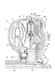
- FIG. 1 shows an example in which a vibration reducing device is provided inside a torque converter 1 which is a fluid transmission device having a torque amplifying function.
- the torque converter 1 shown here is the same as a torque converter widely installed in conventional vehicles. It has the composition of. That is, the pump impeller 2 that is a member on the input side is configured by attaching the pump blades 3 arranged in an annular shape to the inner surface of the pump shell 4, and faces the pump impeller 2 so as to face the driven side member in the present invention.
- the turbine runner 5 corresponding to is arranged.
- the turbine runner 5 has a shape that is substantially symmetric to the pump impeller 2, and is configured by fixing a large number of annularly arranged turbine blades 6 on the inner surface of an annular (or semi-doughnut-shaped) shell. Has been. Accordingly, the pump impeller 2 and the turbine runner 5 are arranged to face each other on the same axis.
- a front cover 7 covering the outer peripheral side of the turbine runner 5 is integrally joined to the outer peripheral end of the pump shell 4.
- the front cover 7 is a so-called bottomed cylindrical member having a front wall surface facing the inner surface of the pump shell 4, and oil is sealed in the inside thereof. Therefore, when the power is transmitted to the turbine runner 5 and rotated, a fluid flow enclosed in the front cover 7 is generated, and the turbine runner 5 rotates by the fluid flow to transmit the power.
- a cylindrical member 8 protruding toward the outer surface is integrally formed at the center of the front cover 7, and an engine output shaft (not shown) is inserted into the hollow portion of the cylindrical member 8.
- a plurality of nuts 9 for connecting to a drive plate (not shown) that rotates integrally with the output shaft of the engine are provided on the outer surface on the outer peripheral side of the front cover 7 in the circumferential direction. Power is transmitted to the cover 7.
- a cylindrical shaft 10 is integrally provided at an inner peripheral end portion of the pump shell 4, and the cylindrical shaft 10 extends to the back side (opposite side of the engine side) of the pump shell 4. Not connected to the oil pump.
- a fixed shaft 11 having an outer diameter smaller than the inner diameter of the cylindrical shaft 10 is inserted into the cylindrical shaft 10, and the tip portion of the torque converter 1 surrounded by the pump shell 4 and the front cover 7 is inserted. It extends to the inside.
- the distal end portion of the fixed shaft 11 is located on the inner peripheral side of the turbine runner 5 described above or the inner peripheral side of the portion between the pump impeller 2 and the turbine runner 5.
- the inner race of the clutch 12 is spline-fitted.
- a stator 13 disposed between the inner peripheral portion of the pump impeller 2 and the inner peripheral portion of the turbine runner 5 facing the outer periphery of the one-way clutch 12 is attached. That is, in a state where the speed ratio between the pump impeller 2 and the turbine runner 5 is small, the rotation of the stator 13 is prevented by the one-way clutch 12 even if the oil flowing out from the turbine runner 5 acts on the stator 13. In a state where oil is fed into the pump impeller 2 by changing the flow direction of the oil and the speed ratio becomes large and the oil strikes the so-called back surface of the stator 13, the stator 13 is rotated so as not to disturb the oil flow. It is configured.
- An output shaft (input shaft of a transmission (not shown)) 14 is rotatably inserted on the inner peripheral side of the fixed shaft 11, and its distal end protrudes (beyons) the distal end of the fixed shaft 11.
- a hub shaft 15 is spline-fitted to the outer periphery of the front end that extends from the fixed shaft 11 and extends near the inner surface of the front cover 7.
- the hub shaft 15 is formed with a flange-shaped hub 16 projecting to the outer peripheral side.
- the turbine runner 5 described above, a rolling element holding member 17 described later, and an output side constituting a torsional damper are formed on the hub 16.
- the plate 18 is connected to the hub 16 by a rivet 19 so as to be integrated. Specifically, the turbine runner 5, the rolling element holding member 17, the output side plate 18, and the hub 16 are arranged in this order along the axial direction, and the members 5, 17, 18, and 16 are integrated by the rivet 19. Yes.
- the output side plate 18 is an annular plate
- the input side plate 20 is disposed so as to face the plate 18.
- the input side plate 20 is integrated with the output side plate 18 by rivets or bolts (not shown), and rotates relative to the plates 18 and 20 between the input side plate 20 and the output side plate 18.
- the center plate 21 is arranged so that it is possible.
- the center plate 21 is configured to transmit power to the input side plate 20 and the output side plate 18 via a spring 22. Therefore, in the example shown in FIG. 1, the center plate 21 formed in an annular shape is used.
- Through-holes 21a are formed in the input side plate 20 and the output-side plate 18 so that the same positions as the positions where the through-holes 21a are formed in the radial direction are separated from each other, or the gap between both is increased.
- the spring 22 is disposed in the gap 20a so as to be contracted in the circumferential direction. That is, the spring 22 is configured to be compressed when the center plate 21 rotates relative to the input side plate 20 and the output side plate 18. Therefore, in the example shown in FIG. 1, when power is transmitted from the center plate 21 to the input side plate 20 and the output side plate 18, vibration based on torque fluctuations of the transmitted power can be damped by the spring 22. it can.
- a lock-up clutch 23 is provided on the outer peripheral side of the hub shaft 15 on the engine side from the hub 16.
- the lockup clutch 23 is configured such that the piston moves in the axial direction in accordance with the hydraulic pressure difference between the front and back surfaces of the piston, and can be configured in the same manner as a conventionally known lockup clutch. .
- the configuration of the lock-up clutch 23 will be described in detail.
- the lock-up piston 24 formed in an annular shape, the inner periphery of the lock-up piston 24 bent toward the engine side, and rotatable relative to the hub shaft 15.
- a friction plate 26 provided on a wall surface on the outer peripheral side of the lock-up piston 24, more specifically, on a wall surface facing the front cover 7.
- the lock-up piston 24 moves to the front cover 7 side and the friction plate 26 and the inner wall surface of the front cover 7 come into contact with each other and are connected. Is done. That is, the lockup piston 24 and the front cover 7 are mechanically connected. As a result, the power transmitted to the front cover 7 is directly input to the lockup piston 24.
- the outer peripheral side of the lock-up piston 24 is bent to the output side, that is, the hub 16 side, and the bent cylindrical portion 24a and the center plate 21 are connected by a sleeve or the like. Yes. That is, the cylindrical portion 24a and the center plate 21 can be relatively moved in the axial direction, and the cylindrical portion 24a and the center plate 21 can be rotated together.
- the lock-up clutch 23 is configured to be engaged when the speed ratio between the input rotation speed and the output rotation speed of the torque converter 1 shown in the figure is 1, and the torque converter 1 shown in the figure is engaged. The lockup clutch 23 is engaged when the mounted vehicle is traveling normally.
- the rolling element holding member 17 integrated between the turbine runner 5 and the hub 16 is formed in an annular shape and is fitted to the hub shaft 15. Further, an annular convex portion 27 having a predetermined thickness is formed on the outer peripheral side of the rolling element holding member 17.
- the annular protrusion 27 is for holding the rolling element 28. In order to improve the effect of reducing the vibration by the rolling element 28 swinging, the annular protruding part 27 is held on the outer peripheral side.
- the annular convex portion 27 has a predetermined length in the radial direction and holds the rolling elements 28 on the tip end side, that is, the outer peripheral side.
- the formed rolling element 28 is inserted and held in the insertion hole 27a. That is, as shown in FIG. 1, the center part is inserted in the insertion hole 27a, and both ends thereof are configured to limit the movement of the rolling element 28 in the axial direction.
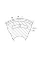
- the inner wall surface 27b on the outer peripheral side of the insertion hole 27a is formed to swing the rolling element 28 in accordance with the order of torque vibration input to the front cover 7 when the lockup clutch 23 is engaged. ing. That is, the square root of a value obtained by dividing the distance R from the center of rotation of the rolling element 28 to the center of rotation of the hub shaft 15 by the distance L from the center of gravity of the rolling element 28 to the center of rotation of the rolling element 28.
- the shape of the wall surface facing the inner wall surface 27b is not particularly limited.
- the rolling element 28 shown in the figure has large both end portions in order to prevent the rolling element 28 from detaching in the axial direction from the insertion hole 27a formed in the annular convex portion 27.
- the shape of the rolling element 28 is not limited. In short, it may be configured so that the rolling element 28 can swing along the inner wall surface 27b in the insertion hole 27a.
- the rolling element 28 swings along the inner wall surface 27b of the insertion hole 27a formed in the annular protrusion 27, the rolling element 28 and the inner wall surface 27b of the insertion hole 27a formed in the annular protrusion 27
- the surface of the rolling element 28 may be coated with a resin, and grease is applied to the outer peripheral surface of the rolling element 28 or the inner wall surface 27b of the insertion hole 27a formed in the annular protrusion 27. May be.
- a case member is provided to place the rolling element 28 in a so-called dry state, that is, a state where no lubricating oil is supplied.
- case members 29 and 30 each having a bottomed cylindrical shape are provided on both surfaces of the annular convex portion 27 so as to surround the insertion hole 27 a in the annular convex portion 27. That is, the case members 29 and 30 are arranged such that their opening portions open toward the annular convex portion 27.
- These case members 29 and 30 correspond to the plates in the present invention.
- annular convex part 27 are connected so that it can rotate relatively via the seal members 31 and 32.
- the sealing members 31 and 32 seal the oil from flowing into the portion where the rolling element 28 is accommodated, that is, the rolling chamber 33 from the gap between the case members 29 and 30 and the annular protrusion 27.
- the case members 29 and 30 are connected so as to be able to rotate relative to the annular protrusion 27. Therefore, the seal members 31 and 32 are formed of relatively soft members, and are, for example, bellows-like members formed of rubber or resin material. In the example shown in FIG. 1, the seal members 31 and 32 are formed in an annular shape, and the seal members 31 and 32 and the annular protrusion 27 or the case members 29 and 30 are bonded or welded.
- the rolling chamber 33 is formed by the case members 29 and 30, the viscous resistance due to the viscosity of the oil does not act on the rolling element 28, so the order in which the rolling element 28 swings changes. Can be suppressed or prevented. Further, the case members 29 and 30 and the annular convex portion 27 are connected so as to be able to relatively rotate. That is, a main vibration system that reduces vibration by the rolling element 28 swinging, that is, a vibration system that rotates integrally with the turbine runner 5, the hub shaft 15, the output shaft 14, and a transmission (not shown), and a case member 29.
- the sealing members 31 and 32 described above are elastic bodies having a predetermined elastic force. That is, it is desirable that the seal members 31 and 32 function so as to apply an elastic force so as to reduce the phase when the annular convex portion 28 and the case members 29 and 30 rotate relatively.
- the seal members 31 and 32 function in this way, the case members 29 and 30 can function as so-called mass dampers. Therefore, as described above, the effect of reducing vibration is improved by the mass ratio, and the case members 29 and 30 When 30 functions as a mass damper, the effect of vibration reduction can be further improved.
- the seal members 31 and 32 are not limited to those bonded or welded to the annular convex portion 27 and the case members 29 and 30 as described above.
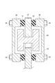
- the sealing members 31 and 32 may be held by being sandwiched between the bolt 34 and the nut 35.
- the configuration shown in FIG. 3 will be specifically described.
- the case members 29 and 30, the annular protrusion 27 and the seal members 31 and 32 are formed with through holes, and the bolts 34 are inserted into the through holes. It is configured.
- the through holes formed in the annular protrusions 27 and the seal members 31 and 32 have a predetermined circumferential direction.
- the sealing member according to the present invention only needs to be able to prevent the inflow of oil, and preferably functions as a mass damper, and it is necessary to provide both functions with only one member such as rubber.
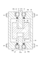
- a member 36 having only a sealing function and an elastic body 37 for applying an elastic force are arranged between the annular convex portion 27 and the case members 29 and 30, respectively. Also good.
- the configuration shown in FIG. 4 is determined in a circumferential direction on the side surface of the annular convex portion 27 and the end surface on the opening side of each case member 29, 30 facing the side surface of the annular convex portion 27.
- the long holes 27a, 29a, and 30a having the length are formed, and the springs 37 are disposed in the long holes 27a, 29a, and 30a so as to expand and contract in the circumferential direction. More specifically, a spring 37 is arranged over both the elongated hole 27a formed in the annular convex portion 27 and the elongated holes 29a and 30a formed in the case members 29 and 30, and the annular convex portion 27 and When the case members 29 and 30 are relatively rotated, one end of the spring 37 is pressed by the end surface of the elongated hole 27a formed in the annular convex portion 27, and the other end is pressed by the case members 29 and 30.
- a seal member 36 such as an O-ring is provided on the inner peripheral side of the spring 37.
- the seal member 36 is configured to seal a gap between the members 27, 29, and 30 by being sandwiched between the annular protrusion 27 and the case members 29, 30. Therefore, even when the annular protrusion 27 and the case members 29 and 30 are relatively rotated, the sealing performance by the seal member 36 is not impaired, and as a result, oil flows into the rolling chamber 33. This can be suppressed or prevented. That is, it is possible to suppress or prevent the change in the order of swinging of the rolling elements 28 due to the viscous resistance of oil.
- the fluid transmission device according to the present invention only needs to have a drive side member and a driven side member, and thus may be a fluid transmission device or a fluid coupling other than the above-described torque converter having a torque amplification action.
Landscapes
- Engineering & Computer Science (AREA)
- General Engineering & Computer Science (AREA)
- Mechanical Engineering (AREA)
- Physics & Mathematics (AREA)
- Acoustics & Sound (AREA)
- Aviation & Aerospace Engineering (AREA)
- Mechanical Operated Clutches (AREA)
- General Details Of Gearings (AREA)
- Vibration Prevention Devices (AREA)
Abstract
Description
n=√(R/L)
Claims (6)
- 回転部材に伝達されるトルクの変化に伴う振動を、前記回転部材に対して相対回転可能に連結された転動体が揺動することにより低減する振動低減装置において、
前記転動体を囲うケース部材と、
前記ケース部材と前記回転部材とを相対回転可能に連結しかつ前記転動体が揺動する空間にオイルが流入しないように封止するシール部材と
を備えていることを特徴とする振動低減装置。 - 前記回転部材と前記ケース部材とが相対回転したときの位相を減少させる弾性部材を更に備えていることを特徴とする請求項1に記載の振動低減装置。
- 前記ケース部材は、前記回転部材の表裏両面にそれぞれ設けられたプレートを含み、
該プレート同士が一体に回転するように連結されていることを特徴とする請求項1または2に記載の振動低減装置。 - 前記回転部材は、流体流により動力を伝達する流体伝動装置の従動側部材と一体に回転し、かつ前記流体伝動装置の内部に配置されていることを特徴とする請求項1ないし3のいずれかに記載の振動低減装置。
- 前記回転部材は、流体流により動力を伝達する流体伝動装置に入力されるトルクを機械的に伝達する直結クラッチの出力部材と一体に回転し、かつ該流体伝動装置の内部に配置されていることを特徴とする請求項1ないし3のいずれかに記載の振動低減装置。
- 前記流体伝動装置は、前記流体流により動力を伝達するとともに、該流体伝動装置に入力された動力を増幅する機能を有するトルクコンバータを含むことを特徴とする請求項4または5に記載の振動低減装置。
Priority Applications (5)
| Application Number | Priority Date | Filing Date | Title |
|---|---|---|---|
| PCT/JP2012/061376 WO2013161058A1 (ja) | 2012-04-27 | 2012-04-27 | 振動低減装置 |
| EP12875289.6A EP2843262B1 (en) | 2012-04-27 | 2012-04-27 | Vibration damping device |
| CN201280072494.3A CN104246301B (zh) | 2012-04-27 | 2012-04-27 | 振动减轻装置 |
| US14/380,178 US9958027B2 (en) | 2012-04-27 | 2012-04-27 | Vibration damping device |
| JP2014512253A JP5862767B2 (ja) | 2012-04-27 | 2012-04-27 | 振動低減装置 |
Applications Claiming Priority (1)
| Application Number | Priority Date | Filing Date | Title |
|---|---|---|---|
| PCT/JP2012/061376 WO2013161058A1 (ja) | 2012-04-27 | 2012-04-27 | 振動低減装置 |
Publications (1)
| Publication Number | Publication Date |
|---|---|
| WO2013161058A1 true WO2013161058A1 (ja) | 2013-10-31 |
Family
ID=49482424
Family Applications (1)
| Application Number | Title | Priority Date | Filing Date |
|---|---|---|---|
| PCT/JP2012/061376 Ceased WO2013161058A1 (ja) | 2012-04-27 | 2012-04-27 | 振動低減装置 |
Country Status (5)
| Country | Link |
|---|---|
| US (1) | US9958027B2 (ja) |
| EP (1) | EP2843262B1 (ja) |
| JP (1) | JP5862767B2 (ja) |
| CN (1) | CN104246301B (ja) |
| WO (1) | WO2013161058A1 (ja) |
Cited By (16)
| Publication number | Priority date | Publication date | Assignee | Title |
|---|---|---|---|---|
| JP2015098931A (ja) * | 2013-11-20 | 2015-05-28 | 株式会社エクセディ | トルクコンバータのロックアップ装置 |
| JP2015098933A (ja) * | 2013-11-20 | 2015-05-28 | 株式会社エクセディ | トルクコンバータのロックアップ装置 |
| JP2015132354A (ja) * | 2014-01-15 | 2015-07-23 | 株式会社エクセディ | 振り子式ダンパ装置及びトルクコンバータのロックアップ装置 |
| DE102014207260A1 (de) * | 2014-04-15 | 2015-10-15 | Zf Friedrichshafen Ag | Torsionsschwingungsdämpfer mit einer Dämpfungseinrichtung, einem Tilgersystem und einer Masseeinrichtung |
| WO2015158496A1 (de) * | 2014-04-15 | 2015-10-22 | Zf Friedrichshafen Ag | Torsionsschwingungsdämpfer mit einer dämpfungseinrichtung, einem tilgersystem und einer masseeinrichtung |
| WO2015198120A1 (en) | 2014-06-25 | 2015-12-30 | Toyota Jidosha Kabushiki Kaisha | Torsional vibration reduction device |
| DE102015109602A1 (de) | 2014-06-27 | 2015-12-31 | Toyota Jidosha Kabushiki Kaisha | Drehmomentwandler mit Torsionsschwingungsdämpfungsvorrichtung |
| CN105221655A (zh) * | 2014-06-27 | 2016-01-06 | 丰田自动车株式会社 | 减振装置 |
| CN105992895A (zh) * | 2013-12-02 | 2016-10-05 | 舍弗勒技术股份两合公司 | 扭矩传递装置 |
| JP2016205427A (ja) * | 2015-04-16 | 2016-12-08 | トヨタ自動車株式会社 | 捩り振動低減装置 |
| US9556944B2 (en) | 2013-11-22 | 2017-01-31 | Toyota Jidosha Kabushiki Kaisha | Vibration damping device |
| CN106468325A (zh) * | 2015-08-20 | 2017-03-01 | 舍弗勒技术股份两合公司 | 离心力摆和具有离心力摆的流体动力学的转矩变换器 |
| JP2017096395A (ja) * | 2015-11-24 | 2017-06-01 | トヨタ自動車株式会社 | 振動低減装置 |
| JP2018123943A (ja) * | 2017-02-03 | 2018-08-09 | 株式会社エクセディ | 動力伝達装置 |
| US10240658B2 (en) * | 2014-01-08 | 2019-03-26 | Toyota Jidosha Kabushiki Kaisha | Torsional vibration damping device |
| US10883565B2 (en) | 2014-08-29 | 2021-01-05 | Exedy Corporation | Hydraulic power transmission device |
Families Citing this family (20)
| Publication number | Priority date | Publication date | Assignee | Title |
|---|---|---|---|---|
| US9435397B2 (en) * | 2012-11-01 | 2016-09-06 | Toyota Jidosha Kabushiki Kaisha | Torsional vibration damping device |
| US9709125B2 (en) * | 2012-12-21 | 2017-07-18 | Schaeffler Technologies AG & Co. KG | Vibration damper |
| JP6090466B2 (ja) * | 2013-09-30 | 2017-03-08 | アイシン・エィ・ダブリュ株式会社 | ダンパ装置および発進装置 |
| US10570964B2 (en) | 2015-03-19 | 2020-02-25 | Honda Motor Co., Ltd. | Vibration absorber |
| US9995366B2 (en) * | 2015-08-14 | 2018-06-12 | GM Global Technology Operations LLC | Torsional vibration absorption system |
| DE102015215891A1 (de) * | 2015-08-20 | 2017-02-23 | Schaeffler Technologies AG & Co. KG | Fliehkraftpendel und hydrodynamischer Drehmomentwandler mit Fliehkraftpendel |
| JP6361617B2 (ja) * | 2015-09-14 | 2018-07-25 | トヨタ自動車株式会社 | 捩り振動低減装置 |
| CN105179635A (zh) * | 2015-10-22 | 2015-12-23 | 上海萨克斯动力总成部件系统有限公司 | 一种集成平行轴式换挡双离合器的液力变矩器 |
| JP6344373B2 (ja) * | 2015-12-07 | 2018-06-20 | マツダ株式会社 | 遠心振子ダンパ付きパワートレインの制御装置 |
| JP6278046B2 (ja) * | 2016-01-06 | 2018-02-14 | マツダ株式会社 | 遠心振子ダンパ付きパワートレインの制御装置 |
| US10563723B2 (en) * | 2016-03-16 | 2020-02-18 | Schaeffler Technologies AG & Co. KG | Integrated slip clutch with drive plate for dry damper applications |
| JP2018017378A (ja) * | 2016-07-29 | 2018-02-01 | ジヤトコ株式会社 | 磁気粘性流体クラッチ付きトルクコンバータ |
| JP6827311B2 (ja) * | 2016-12-12 | 2021-02-10 | 株式会社エクセディ | ダンパ装置 |
| JP6972652B2 (ja) * | 2017-05-15 | 2021-11-24 | トヨタ自動車株式会社 | トルクコンバータ |
| JP2018204726A (ja) * | 2017-06-06 | 2018-12-27 | トヨタ自動車株式会社 | 振り子式捩り振動低減装置 |
| JP6870545B2 (ja) | 2017-09-05 | 2021-05-12 | トヨタ自動車株式会社 | ハイブリッド車両 |
| JP6863253B2 (ja) * | 2017-12-06 | 2021-04-21 | トヨタ自動車株式会社 | 捩り振動低減装置 |
| JP7120206B2 (ja) * | 2019-11-29 | 2022-08-17 | トヨタ自動車株式会社 | 遠心振り子式ダンパ |
| JP2022124037A (ja) * | 2021-02-15 | 2022-08-25 | 株式会社エクセディ | 回転装置、及び動力伝達装置 |
| US20260045849A1 (en) * | 2024-08-12 | 2026-02-12 | Fca Us Llc | Vibration absorber for vehicle electric generator |
Citations (5)
| Publication number | Priority date | Publication date | Assignee | Title |
|---|---|---|---|---|
| JP2000297843A (ja) * | 1999-04-16 | 2000-10-24 | Nok Vibracoustic Kk | ダイナミックダンパ |
| JP2011504987A (ja) | 2007-11-29 | 2011-02-17 | ルーク ラメレン ウント クツプルングスバウ ベタイリグングス コマンディートゲゼルシャフト | 回転数適応型の動吸振器を備えた力伝達装置および減衰特性を改善するための方法 |
| JP2011208774A (ja) * | 2010-03-30 | 2011-10-20 | Toyota Motor Corp | 振動低減装置 |
| WO2012043301A1 (ja) * | 2010-09-30 | 2012-04-05 | アイシン・エィ・ダブリュ株式会社 | 流体伝動装置 |
| WO2012049762A1 (ja) * | 2010-10-15 | 2012-04-19 | トヨタ自動車株式会社 | 振動減衰装置 |
Family Cites Families (17)
| Publication number | Priority date | Publication date | Assignee | Title |
|---|---|---|---|---|
| US2277186A (en) * | 1933-12-04 | 1942-03-24 | Thege Edvin Ossian Parcival | Torsional vibration damper |
| US2636399A (en) * | 1950-06-17 | 1953-04-28 | Houdailie Hershey Corp | Tuned inertia mass viscous damper |
| GB736808A (en) * | 1952-10-08 | 1955-09-14 | Croset Louis Paul | Improvements in or relating to vibration dampers |
| US3552230A (en) * | 1970-03-11 | 1971-01-05 | Houdaille Industries Inc | Optimumly tuned and efficient viscous dampers |
| DE2118864A1 (de) * | 1971-04-19 | 1972-10-26 | Daimler-Benz Ag, 7000 Stuttgart | Drehschwingungsdämpfer für Wellen |
| DE2260318A1 (de) * | 1972-12-09 | 1974-06-12 | Knorr Bremse 1000 Berlin Und 8 | Viskositaets-drehschwingungsdaempfer |
| DE7302115U (de) * | 1973-01-20 | 1978-02-23 | Knorr-Bremse, 1000 Berlin Und 8000 Muenchen | Viskositäts-Drehschwingungsdämpfer |
| US3992963A (en) * | 1975-01-21 | 1976-11-23 | Wallace-Murray Corporation | Elastomer and liquid torsional vibration damper |
| JPS5842844A (ja) * | 1981-09-07 | 1983-03-12 | Shoichi Iwamoto | ダンパ |
| DE19831158A1 (de) * | 1998-07-11 | 2000-01-13 | Freudenberg Carl Fa | Schwungrad |
| DE19831159B4 (de) * | 1998-07-11 | 2004-06-03 | Carl Freudenberg Kg | Drehzahladaptiver Schwingungstilger |
| DE19831154B4 (de) * | 1998-07-11 | 2005-04-21 | Carl Freudenberg Kg | Drehzahladaptiver Schwingungstilger |
| DE10059101B4 (de) * | 2000-11-28 | 2012-12-20 | Zf Friedrichshafen Ag | Antriebssystem |
| DE10236752A1 (de) * | 2002-08-10 | 2004-02-19 | Daimlerchrysler Ag | Antriebsstrang eines Kraftfahrzeuges |
| DE10348725A1 (de) * | 2003-10-16 | 2005-05-19 | Depp, Jürgen Christian, Dr. | Drehschwingungsdämpfer |
| CN102177368B (zh) * | 2008-10-10 | 2013-11-27 | 丰田自动车株式会社 | 流体传动设备 |
| DE102009002481B4 (de) * | 2008-12-10 | 2022-06-02 | Zf Friedrichshafen Ag | Antriebssystem mit Drehmomentübertragungsanordnung und hydrodynamische Kopplungsanordnung |
-
2012
- 2012-04-27 US US14/380,178 patent/US9958027B2/en active Active
- 2012-04-27 WO PCT/JP2012/061376 patent/WO2013161058A1/ja not_active Ceased
- 2012-04-27 EP EP12875289.6A patent/EP2843262B1/en active Active
- 2012-04-27 JP JP2014512253A patent/JP5862767B2/ja not_active Expired - Fee Related
- 2012-04-27 CN CN201280072494.3A patent/CN104246301B/zh not_active Expired - Fee Related
Patent Citations (5)
| Publication number | Priority date | Publication date | Assignee | Title |
|---|---|---|---|---|
| JP2000297843A (ja) * | 1999-04-16 | 2000-10-24 | Nok Vibracoustic Kk | ダイナミックダンパ |
| JP2011504987A (ja) | 2007-11-29 | 2011-02-17 | ルーク ラメレン ウント クツプルングスバウ ベタイリグングス コマンディートゲゼルシャフト | 回転数適応型の動吸振器を備えた力伝達装置および減衰特性を改善するための方法 |
| JP2011208774A (ja) * | 2010-03-30 | 2011-10-20 | Toyota Motor Corp | 振動低減装置 |
| WO2012043301A1 (ja) * | 2010-09-30 | 2012-04-05 | アイシン・エィ・ダブリュ株式会社 | 流体伝動装置 |
| WO2012049762A1 (ja) * | 2010-10-15 | 2012-04-19 | トヨタ自動車株式会社 | 振動減衰装置 |
Cited By (28)
| Publication number | Priority date | Publication date | Assignee | Title |
|---|---|---|---|---|
| JP2015098933A (ja) * | 2013-11-20 | 2015-05-28 | 株式会社エクセディ | トルクコンバータのロックアップ装置 |
| JP2015098931A (ja) * | 2013-11-20 | 2015-05-28 | 株式会社エクセディ | トルクコンバータのロックアップ装置 |
| US9556944B2 (en) | 2013-11-22 | 2017-01-31 | Toyota Jidosha Kabushiki Kaisha | Vibration damping device |
| CN105992895A (zh) * | 2013-12-02 | 2016-10-05 | 舍弗勒技术股份两合公司 | 扭矩传递装置 |
| US10240658B2 (en) * | 2014-01-08 | 2019-03-26 | Toyota Jidosha Kabushiki Kaisha | Torsional vibration damping device |
| JP2015132354A (ja) * | 2014-01-15 | 2015-07-23 | 株式会社エクセディ | 振り子式ダンパ装置及びトルクコンバータのロックアップ装置 |
| WO2015158496A1 (de) * | 2014-04-15 | 2015-10-22 | Zf Friedrichshafen Ag | Torsionsschwingungsdämpfer mit einer dämpfungseinrichtung, einem tilgersystem und einer masseeinrichtung |
| CN106170638B (zh) * | 2014-04-15 | 2019-05-07 | Zf腓特烈斯哈芬股份公司 | 具有减振装置、缓冲系统和质量装置的扭转减振器 |
| DE102014207258A1 (de) * | 2014-04-15 | 2015-10-29 | Zf Friedrichshafen Ag | Torsionsschwingungsdämpfer mit einer Dämpfungseinrichtung, einem Tilgersystem und einer Masseeinrichtung |
| CN106170638A (zh) * | 2014-04-15 | 2016-11-30 | Zf腓特烈斯哈芬股份公司 | 具有减振装置、缓冲系统和质量装置的扭转减振器 |
| DE102014207260A1 (de) * | 2014-04-15 | 2015-10-15 | Zf Friedrichshafen Ag | Torsionsschwingungsdämpfer mit einer Dämpfungseinrichtung, einem Tilgersystem und einer Masseeinrichtung |
| WO2015198120A1 (en) | 2014-06-25 | 2015-12-30 | Toyota Jidosha Kabushiki Kaisha | Torsional vibration reduction device |
| JP2016008668A (ja) * | 2014-06-25 | 2016-01-18 | トヨタ自動車株式会社 | 捩り振動低減装置 |
| CN106461013B (zh) * | 2014-06-25 | 2019-03-22 | 丰田自动车株式会社 | 扭转振动降低装置 |
| US10066720B2 (en) | 2014-06-25 | 2018-09-04 | Toyota Jidosha Kabushiki Kaisha | Torsional vibration reduction device |
| CN106461013A (zh) * | 2014-06-25 | 2017-02-22 | 丰田自动车株式会社 | 扭转振动降低装置 |
| US9518631B2 (en) | 2014-06-27 | 2016-12-13 | Toyota Jidosha Kabushiki Kaisha | Vibration damping device |
| US9671002B2 (en) | 2014-06-27 | 2017-06-06 | Toyota Jidosha Kabushiki Kaisha | Torque converter having torsional vibration damping device |
| DE102015109602B4 (de) * | 2014-06-27 | 2017-09-14 | Toyota Jidosha Kabushiki Kaisha | Drehmomentwandler mit Torsionsschwingungsdämpfungsvorrichtung |
| JP2016011702A (ja) * | 2014-06-27 | 2016-01-21 | トヨタ自動車株式会社 | 振動低減装置 |
| CN105221655A (zh) * | 2014-06-27 | 2016-01-06 | 丰田自动车株式会社 | 减振装置 |
| DE102015109602A1 (de) | 2014-06-27 | 2015-12-31 | Toyota Jidosha Kabushiki Kaisha | Drehmomentwandler mit Torsionsschwingungsdämpfungsvorrichtung |
| US10883565B2 (en) | 2014-08-29 | 2021-01-05 | Exedy Corporation | Hydraulic power transmission device |
| JP2016205427A (ja) * | 2015-04-16 | 2016-12-08 | トヨタ自動車株式会社 | 捩り振動低減装置 |
| CN106468325A (zh) * | 2015-08-20 | 2017-03-01 | 舍弗勒技术股份两合公司 | 离心力摆和具有离心力摆的流体动力学的转矩变换器 |
| JP2017096395A (ja) * | 2015-11-24 | 2017-06-01 | トヨタ自動車株式会社 | 振動低減装置 |
| JP2018123943A (ja) * | 2017-02-03 | 2018-08-09 | 株式会社エクセディ | 動力伝達装置 |
| WO2018142890A1 (ja) * | 2017-02-03 | 2018-08-09 | 株式会社エクセディ | 動力伝達装置 |
Also Published As
| Publication number | Publication date |
|---|---|
| CN104246301A (zh) | 2014-12-24 |
| JPWO2013161058A1 (ja) | 2015-12-21 |
| US20150005078A1 (en) | 2015-01-01 |
| EP2843262B1 (en) | 2019-11-27 |
| JP5862767B2 (ja) | 2016-02-16 |
| US9958027B2 (en) | 2018-05-01 |
| EP2843262A1 (en) | 2015-03-04 |
| CN104246301B (zh) | 2017-09-26 |
| EP2843262A4 (en) | 2015-12-09 |
Similar Documents
| Publication | Publication Date | Title |
|---|---|---|
| JP5862767B2 (ja) | 振動低減装置 | |
| JP5850132B2 (ja) | 振動低減装置 | |
| CN102906459B (zh) | 液力联接装置、特别是变矩器 | |
| JP5900469B2 (ja) | 振動低減装置 | |
| US10208832B2 (en) | Centrifugal pendulum-type vibration absorbing device and designing method for the same | |
| CN107002850A (zh) | 具有涡轮‑活塞锁定离合器的流体动力学扭矩联接装置及相关方法 | |
| KR20180103009A (ko) | 비틀림 진동 저감 장치 | |
| JPWO2016047789A1 (ja) | ダンパ装置 | |
| CN106461013A (zh) | 扭转振动降低装置 | |
| US10634227B2 (en) | Torque converter | |
| CN105937579B (zh) | 扭振减小装置 | |
| JP6176997B2 (ja) | トルクコンバータのロックアップ装置 | |
| JP5716645B2 (ja) | 捩り振動低減装置 | |
| JP7173701B2 (ja) | 捩り振動低減装置 | |
| JP2014206244A (ja) | トルクコンバータのロックアップ装置 | |
| WO2016167013A1 (ja) | 動吸振装置 | |
| WO2014148467A1 (ja) | トルクコンバータのロックアップ装置 | |
| JP6492916B2 (ja) | 捩り振動低減装置 | |
| WO2016167025A1 (ja) | 動吸振装置 | |
| JP2011099545A (ja) | 捩り振動減衰装置 | |
| JP2020070875A (ja) | 捩り振動低減装置 | |
| JP2017096395A (ja) | 振動低減装置 | |
| JP2016200238A (ja) | 動吸振装置 |
Legal Events
| Date | Code | Title | Description |
|---|---|---|---|
| 121 | Ep: the epo has been informed by wipo that ep was designated in this application |
Ref document number: 12875289 Country of ref document: EP Kind code of ref document: A1 |
|
| ENP | Entry into the national phase |
Ref document number: 2014512253 Country of ref document: JP Kind code of ref document: A |
|
| WWE | Wipo information: entry into national phase |
Ref document number: 14380178 Country of ref document: US |
|
| WWE | Wipo information: entry into national phase |
Ref document number: 2012875289 Country of ref document: EP |
|
| NENP | Non-entry into the national phase |
Ref country code: DE |