WO2013161908A1 - Pet-mri装置 - Google Patents
Pet-mri装置 Download PDFInfo
- Publication number
- WO2013161908A1 WO2013161908A1 PCT/JP2013/062131 JP2013062131W WO2013161908A1 WO 2013161908 A1 WO2013161908 A1 WO 2013161908A1 JP 2013062131 W JP2013062131 W JP 2013062131W WO 2013161908 A1 WO2013161908 A1 WO 2013161908A1
- Authority
- WO
- WIPO (PCT)
- Prior art keywords
- pet
- pet detector
- bore
- magnetic field
- detector
- Prior art date
- Legal status (The legal status is an assumption and is not a legal conclusion. Google has not performed a legal analysis and makes no representation as to the accuracy of the status listed.)
- Ceased
Links
Images


Classifications
-
- G—PHYSICS
- G01—MEASURING; TESTING
- G01R—MEASURING ELECTRIC VARIABLES; MEASURING MAGNETIC VARIABLES
- G01R33/00—Arrangements or instruments for measuring magnetic variables
- G01R33/20—Arrangements or instruments for measuring magnetic variables involving magnetic resonance
- G01R33/44—Arrangements or instruments for measuring magnetic variables involving magnetic resonance using nuclear magnetic resonance [NMR]
- G01R33/48—NMR imaging systems
- G01R33/4808—Multimodal MR, e.g. MR combined with positron emission tomography [PET], MR combined with ultrasound or MR combined with computed tomography [CT]
- G01R33/481—MR combined with positron emission tomography [PET] or single photon emission computed tomography [SPECT]
-
- A—HUMAN NECESSITIES
- A61—MEDICAL OR VETERINARY SCIENCE; HYGIENE
- A61B—DIAGNOSIS; SURGERY; IDENTIFICATION
- A61B5/00—Measuring for diagnostic purposes; Identification of persons
- A61B5/0033—Features or image-related aspects of imaging apparatus, e.g. for MRI, optical tomography or impedance tomography apparatus; Arrangements of imaging apparatus in a room
- A61B5/0035—Features or image-related aspects of imaging apparatus, e.g. for MRI, optical tomography or impedance tomography apparatus; Arrangements of imaging apparatus in a room adapted for acquisition of images from more than one imaging mode, e.g. combining MRI and optical tomography
-
- A—HUMAN NECESSITIES
- A61—MEDICAL OR VETERINARY SCIENCE; HYGIENE
- A61B—DIAGNOSIS; SURGERY; IDENTIFICATION
- A61B5/00—Measuring for diagnostic purposes; Identification of persons
- A61B5/05—Detecting, measuring or recording for diagnosis by means of electric currents or magnetic fields; Measuring using microwaves or radio waves
- A61B5/055—Detecting, measuring or recording for diagnosis by means of electric currents or magnetic fields; Measuring using microwaves or radio waves involving electronic [EMR] or nuclear [NMR] magnetic resonance, e.g. magnetic resonance imaging
-
- A—HUMAN NECESSITIES
- A61—MEDICAL OR VETERINARY SCIENCE; HYGIENE
- A61B—DIAGNOSIS; SURGERY; IDENTIFICATION
- A61B5/00—Measuring for diagnostic purposes; Identification of persons
- A61B5/70—Means for positioning the patient in relation to the detecting, measuring or recording means
- A61B5/704—Tables
-
- A—HUMAN NECESSITIES
- A61—MEDICAL OR VETERINARY SCIENCE; HYGIENE
- A61B—DIAGNOSIS; SURGERY; IDENTIFICATION
- A61B6/00—Apparatus or devices for radiation diagnosis; Apparatus or devices for radiation diagnosis combined with radiation therapy equipment
- A61B6/02—Arrangements for diagnosis sequentially in different planes; Stereoscopic radiation diagnosis
- A61B6/03—Computed tomography [CT]
- A61B6/037—Emission tomography
-
- G—PHYSICS
- G01—MEASURING; TESTING
- G01R—MEASURING ELECTRIC VARIABLES; MEASURING MAGNETIC VARIABLES
- G01R33/00—Arrangements or instruments for measuring magnetic variables
- G01R33/20—Arrangements or instruments for measuring magnetic variables involving magnetic resonance
- G01R33/28—Details of apparatus provided for in groups G01R33/44 - G01R33/64
- G01R33/30—Sample handling arrangements, e.g. sample cells, spinning mechanisms
- G01R33/307—Sample handling arrangements, e.g. sample cells, spinning mechanisms specially adapted for moving the sample relative to the MR system, e.g. spinning mechanisms, flow cells or means for positioning the sample inside a spectrometer
-
- G—PHYSICS
- G01—MEASURING; TESTING
- G01R—MEASURING ELECTRIC VARIABLES; MEASURING MAGNETIC VARIABLES
- G01R33/00—Arrangements or instruments for measuring magnetic variables
- G01R33/20—Arrangements or instruments for measuring magnetic variables involving magnetic resonance
- G01R33/28—Details of apparatus provided for in groups G01R33/44 - G01R33/64
- G01R33/38—Systems for generation, homogenisation or stabilisation of the main or gradient magnetic field
- G01R33/385—Systems for generation, homogenisation or stabilisation of the main or gradient magnetic field using gradient magnetic field coils
-
- G—PHYSICS
- G01—MEASURING; TESTING
- G01T—MEASUREMENT OF NUCLEAR OR X-RADIATION
- G01T1/00—Measuring X-radiation, gamma radiation, corpuscular radiation, or cosmic radiation
- G01T1/16—Measuring radiation intensity
- G01T1/1603—Measuring radiation intensity with a combination of at least two different types of detectors
Definitions
- Embodiments of the present invention relate to a PET (Positron Emission Tomography) -MRI (Magnetic Resonance Imaging) apparatus.
- a PET-MRI apparatus that combines a PET (Positron Emission Tomography) apparatus and an MRI (Magnetic Resonance Imaging) apparatus has been commercialized.
- a PET-MRI apparatus is realized by mounting a PET detector on the MRI apparatus, but the position of the PET detector is often fixed.
- a high-power RF (Radio Frequency) magnetic field generated at the magnetic field center and a high-frequency coil (RF coil) that detects the generated magnetic resonance signal and the PET are used. There may be cases where the data is not properly collected due to interference with the detector.
- RF Radio Frequency
- the problem to be solved by the present invention is to suppress the influence on data collection due to interference between a high-power RF magnetic field generated at the center of a magnetic field and a high-frequency coil that detects a generated magnetic resonance signal and a PET detector. It is to provide a PET-MRI apparatus capable of performing the above.
- the PET-MRI apparatus includes a gantry having a static magnetic field magnet, a gradient magnetic field coil, and a high frequency coil, a PET detector, and a moving mechanism.
- the static magnetic field magnet generates a static magnetic field in a substantially cylindrical bore.
- the gradient magnetic field coil is arranged on the inner peripheral side of the static magnetic field magnet, and applies a gradient magnetic field to the subject arranged in the bore.
- the high frequency coil is disposed on the inner peripheral side of the gradient magnetic field coil, and applies a high frequency magnetic field to the subject.
- the PET detector detects gamma rays emitted from a positron emitting nuclide administered to the subject.
- the moving mechanism moves the PET detector along the axial direction of the bore within the gantry.
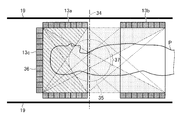
- FIG. 1 is a diagram showing an overall configuration of the PET-MRI apparatus according to the first embodiment.
- FIG. 2 is a diagram illustrating an example of a moving mechanism of the PET detector according to the first embodiment.
- FIG. 3 is a diagram illustrating an example of a moving mechanism of the PET detector according to the second embodiment.
- FIG. 4 is a diagram illustrating an example of a moving mechanism of the PET detector according to the third embodiment.
- FIG. 5 is a diagram (1) illustrating an example of a moving mechanism of the PET detector according to the fourth embodiment.
- FIG. 6 is a diagram (2) illustrating an example of the moving mechanism of the PET detector according to the fourth embodiment.
- FIG. 7 is a diagram illustrating an example of a moving mechanism of the PET detector according to the fifth embodiment.
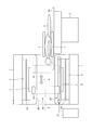
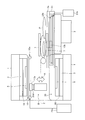
- FIG. 1 is a diagram showing an overall configuration of the PET-MRI apparatus according to the first embodiment.
- FIG. 2 is a diagram illustrating an example of a moving mechanism of the PET detector according to the first embodiment.
- FIG. 3 is a diagram
- FIG. 8 is a diagram illustrating an example of a moving mechanism of the PET detector according to the sixth embodiment.
- FIG. 9 is a diagram illustrating an example of a moving mechanism of the PET detector according to the seventh embodiment.
- FIG. 10 is a diagram illustrating an example of a moving mechanism of the PET detector according to the eighth embodiment.
- FIG. 11 is a diagram (1) illustrating an example of an effective imaging region of the PET detector according to the eighth embodiment.
- FIG. 12 is a diagram (2) illustrating an example of an effective imaging region of the PET detector according to the eighth embodiment.
- FIG. 1 is a diagram showing an overall configuration of the PET-MRI apparatus according to the first embodiment.
- a PET-MRI apparatus 100 includes a static magnetic field magnet 1, a bed 2, a gradient magnetic field coil 3, a gradient magnetic field coil drive circuit 4, and a transmission high-frequency coil 5.
- a data collection unit 15, a PET image reconstruction unit 16, a sequence controller 17, a high frequency shield 18, and a bore cover 19 are provided.
- the static magnetic field magnet 1 generates a static magnetic field in the substantially cylindrical bore B.
- the bed 2 has a top 2a on which the subject P is placed.
- the bed 2 moves the subject P into the static magnetic field by moving the top plate 2a in the longitudinal direction into the bore B along the axial direction of the bore B during imaging.
- the gradient magnetic field coil 3 applies to the subject P gradient magnetic fields Gx, Gy, and Gz whose magnetic field strength changes linearly in the X, Y, and Z directions.
- the gradient magnetic field coil 3 is formed in a substantially cylindrical shape and is disposed on the inner peripheral side of the static magnetic field magnet 1.
- the gradient coil driving circuit 4 drives the gradient coil 3 under the control of the sequence controller 17.
- the transmission high-frequency coil 5 applies a high-frequency magnetic field to the subject P placed in the static magnetic field based on the high-frequency pulse transmitted from the transmission unit 6.
- the transmission high-frequency coil 5 is formed in a substantially cylindrical shape and is disposed on the inner peripheral side of the gradient magnetic field coil 3.
- the transmission unit 6 transmits high frequency pulses to the transmission high frequency coil 5 under the control of the sequence controller 17.
- the receiving high-frequency coil 7 detects a magnetic resonance signal emitted from the subject P by applying a high-frequency magnetic field and a gradient magnetic field.
- the reception high-frequency coil 7 is a surface coil that is disposed on the surface of the subject P in accordance with the region to be imaged.
- the two receiving high-frequency coils 7 are arranged on the upper and lower sides of the subject P.
- the receiving unit 8 receives the magnetic resonance signal detected by the receiving high-frequency coil 7 under the control of the sequence controller 17 and sends the received magnetic resonance signal to the MR data collecting unit 9.
- the MR data collection unit 9 collects magnetic resonance signals sent from the reception unit 8 under the control of the sequence controller 17.
- the MR data collection unit 9 amplifies and detects the collected magnetic resonance signal, performs A / D conversion, and sends it to the computer 10.
- the computer 10 is controlled by the console 11 and reconstructs an MR image based on the magnetic resonance signal sent from the MR data collection unit 9. Then, the computer 10 displays the reconstructed MR image on the display 12.
- the PET detector 13 detects gamma rays (including annihilation radiation) emitted from the positron emitting nuclide administered to the subject P as counting information.
- the PET detector 13 is formed in a ring shape and is disposed on the outer peripheral side of the transmission high-frequency coil 5.
- the PET detector 13 is formed by arranging a detector module having a scintillator and a photodetector in a ring shape.
- the scintillator is, for example, LYSO (Lutetium Yttrium Oxyorthosilicate), LSO (Lutetium Oxyorthosilicate), LGSO (Lutetium Gadolinium Oxyorthosilicate), or the like.
- the photodetector is, for example, a semiconductor detector such as an APD (Avalanche Photodiode) element or SiPM (Silicon Photomultiplier), or a photomultiplier tube (PMT). Then, the PET detector 13 sends the detected count information to the PET data collection unit 15 via the signal line 14.
- APD Anavalanche Photodiode
- SiPM Silicon Photomultiplier
- PMT photomultiplier tube
- the PET data collection unit 15 generates coincidence counting information under the control of the sequence controller 17.
- the PET data collection unit 15 uses the gamma ray count information detected by the PET detector 13 to generate, as coincidence count information, a combination of count information obtained by detecting gamma rays emitted from the positron emitting nuclide almost simultaneously.
- the PET image reconstruction unit 16 reconstructs a PET image using the coincidence counting information generated by the PET data collection unit 15 as projection data.
- the PET image reconstructed by the PET image reconstruction unit 16 is transmitted to the computer 10 and displayed on the display 12.
- the sequence controller 17 receives various types of imaging sequence information executed at the time of imaging from the computer 10 and controls each unit described above.
- the high frequency shield 18 is arranged between the gradient magnetic field coil 3 and the transmission high frequency coil 5 and shields the high frequency magnetic field generated by the transmission high frequency coil 5.
- the bore cover 19 is a cover that covers the inner peripheral side of the transmission high-frequency coil 5.
- the bore cover 19 forms a bore B, which is a substantially cylindrical space, inside a substantially cylindrical structure constituted by the static magnetic field magnet 1, the gradient magnetic field coil 3, the high frequency shield 18, and the transmission high frequency coil 5.
- the PET-MRI apparatus 100 further includes a moving mechanism 20 that moves the PET detector 13 along the axial direction of the bore.
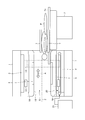
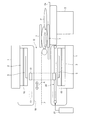
- FIG. 2 is a diagram illustrating an example of a moving mechanism of the PET detector according to the first embodiment.
- the PET detector 13 is disposed between the transmission high-frequency coil 5 and the bore cover 19.
- the moving mechanism 20 is also disposed between the transmission high-frequency coil 5 and the bore cover 19.
- the moving mechanism 20 moves the PET detector 13 along the axial direction of the bore within the gantry.
- the moving mechanism 20 moves the PET detector 13 in the direction of the axis Z of the bore B within the space formed between the high-frequency coil 5 and the bore cover 19 (the direction of the double arrow A shown in FIG. 2).
- the moving mechanism 20 is driven by a driving device 21 to move the PET detector 13.
- the moving mechanism 20 has at least two arranged along the axial direction of the bore B at the end of a gantry composed of the static magnetic field magnet 1, the gradient magnetic field coil 3, the transmission high-frequency coil 5, the bore cover 19, and the like. It is composed of a rotating shaft and a belt spanned around these rotating shafts. Then, when the drive device 21 rotates the rotation shaft, the PET detector 13 fixed to a part of the belt is moved in the Z-axis direction of the bore B.
- the PET-MRI apparatus has been described above.
- the position of the PET detector is often fixed.
- PET-MRI apparatuses in which the PET detector can be removed, but even in such a case, the position of the PET detector is often fixed.
- a PET-MRI apparatus has been proposed in which two PET detectors are arranged at an interval, but the PET detectors do not necessarily have to be arranged around the imaging center and may be slightly shifted.
- the PET detector and the high-frequency coil are less likely to interfere with each other if the axial position of the bore is shifted, which is suitable for mutual data collection.
- imaging by MRI is limited to the center position in the axial direction of the bore, but imaging by PET can be performed anywhere in the axial direction of the bore.
- the target position for imaging by PET is always at the center of the magnetic field, so that an imaging protocol combining MRI and PET can be constructed. It may be inconvenient.
- the PET detector 13 is moved to the position away from the magnetic field center by moving the PET detector 13 in the axial direction of the bore by the moving mechanism 20. can do. Thereby, it is possible to suppress the influence on the data collection due to the interference between the PET detector and the magnetic field. In addition, the degree of freedom in constructing an imaging protocol combining MRI and PET can be increased.
- the moving mechanism of the PET detector is not limited to the example shown in FIG. In the following, other examples of the moving mechanism will be described as the second to eighth embodiments.
- FIG. 3 is a diagram illustrating an example of a moving mechanism of the PET detector according to the second embodiment.
- the PET detector 13 is disposed between the gradient coil 3 and the high-frequency shield 18.
- the moving mechanism 20 is also disposed between the gradient coil 3 and the high-frequency shield 18.
- the moving mechanism 20 moves the PET detector 13 along the axial direction of the bore within the gantry.
- the moving mechanism 20 is driven by the drive device 21 to move the PET detector 13 in the bore Z-axis direction within a space formed between the gradient coil 3 and the high-frequency shield 18 (see FIG. Direction of double arrow A shown in FIG.
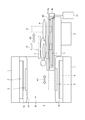
- FIG. 4 is a diagram illustrating an example of a moving mechanism of the PET detector according to the third embodiment.
- the top plate is divided into a top plate 2a on which the subject P is placed and a top plate 2b that supports the top plate 2a from below.
- the top plate 2a is placed on the top plate 2b so that the relative position with the top plate 2b does not change.
- the bed 2 moves the top plate 2b into the bore B in a state where the top plate 2a is placed on the top plate 2b (in the direction of a double arrow A1 shown in FIG. 4).
- the PET detector 13 is provided on the top plate so as to be movable in the longitudinal direction of the top plate.
- the PET detector 13 is disposed in a groove formed on the top plate 2b along the longitudinal direction of the top plate 2b, and is supported so as to be movable in the longitudinal direction of the top plate 2b.
- the moving mechanism 20 is provided in a top plate. Then, the moving mechanism 20 is driven by, for example, the driving device 21 to move the PET detector 13 in the longitudinal direction of the top plate 2b (the direction of the double arrow A2 shown in FIG. 4).
- the PET detector 13 can be moved in the direction of the axis Z of the bore B along with the movement of the top plate 2b. Even when the position of the top plate 2b is fixed, the top plate 2b It is also possible to move in the axis Z direction of the bore B along the longitudinal direction.
- the PET detector 13 may be provided so as to be detachable from the top plate 2b. In that case, for example, a connector for connecting a control line and a power supply line of the PET detector 13 is arranged on the top plate 2b.
- FIG. 5 and 6 are diagrams illustrating an example of a moving mechanism of the PET detector according to the fourth embodiment.
- the top plate is divided into a top plate 2a on which the subject P is placed and a top plate 2b on which the top plate 2a is placed. It is done.
- the positional relationship between the top plate 2a and the top plate 2b and the operation of the bed 2 are the same as in the third embodiment.
- the PET detector is divided into a first PET detector 13a and a second PET detector 13b.
- the first PET detector 13a is disposed around the bore B
- the second PET detector 13b is disposed on the top plate.
- the moving mechanism is also divided into a first moving mechanism 20a and a second moving mechanism 20b. Then, as shown in FIG. 5, the first moving mechanism 20a moves the PET detector 13a along the axial direction of the bore within the gantry.
- the first moving mechanism 20a is driven by the drive device 21a to move the first PET detector 13a around the bore B along the axis Z direction of the bore B (a double arrow shown in FIG. 5). Direction of A1).
- the second moving mechanism 20b is driven by, for example, the driving device 21b to move the second PET detector 13b along the longitudinal direction of the top plate 2b (the direction of the double arrow A2 shown in FIG. 5). .
- FIG. 6 shows a state in which the PET detectors 13a and 13b and the periphery thereof are viewed from the axial direction Z of the bore B.
- the PET detectors 13a and 13b are each formed in an arc shape.
- the PET detector 13a is arranged on the upper side of the bore B with the inner peripheral side of the arc facing the bore B side.
- the PET detector 13b is arranged on the top plate 2b with the inner circumference side of the arc facing the bore B side.
- the PET detector is divided into a PET detector 13a provided on the gantry side and a PET detector 13b provided on the top plate side. It can be moved in the direction of the axis Z of B. Then, the top plate 2b is inserted into the bore B, and data collection is performed when the position of the first PET detector 13a and the position of the second PET detector 13b match in the axis Z direction of the bore B. .
- the PET detector 13b may be provided so as to be detachable from the top plate 2b.
- a connector for connecting a control line and a power supply line of the PET detector 13b is arranged on the top plate 2b.
- the first PET detector 13a may be controlled so that it cannot move at least while the subject P is inserted.
- FIG. 7 is a diagram illustrating an example of a moving mechanism of the PET detector according to the fifth embodiment.
- the first movement mechanism 20a shown in FIG. 5 further moves the first PET detector 13a in the vertical direction via the vertical movement mechanism 20d (FIG. 7).
- the direction of the double arrow A shown in FIG. Further, as shown in FIG. 7, the first moving mechanism 20a moves the PET detector 13a along the axial direction of the bore within the gantry.
- the PET detector 13a can be moved not only in the axis Z direction of the bore B but also in the vertical direction. Thereby, for example, the distance between the two PET detectors can be adjusted according to the size of the subject P.
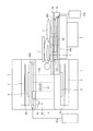
- FIG. 8 is a diagram illustrating an example of a moving mechanism of the PET detector according to the sixth embodiment.
- the PET detector 13 is provided movably outside the static magnetic field magnet 1.
- the bore cover 19 is formed so as to protrude from the static magnetic field magnet 1 on the side where the bed 2 is not placed.
- the moving mechanism 20 is provided so as to extend into a space formed inside the protruding portion of the bore cover 19. Then, the moving mechanism 20 moves the PET detector 13 along the axis Z direction of the bore B (the direction of the double arrow A shown in FIG. 8). Further, as shown in FIG. 8, the moving mechanism 20 moves the PET detector 13 along the axial direction of the bore within the gantry. Thereby, the moving mechanism 20 can move the PET detector 13 to the outside of the static magnetic field magnet 1 by moving the PET detector 13 to the inside of the portion of the bore cover 19 protruding from the static magnetic field magnet 1.
- the PET detector 13 since the PET detector 13 can be moved to the outside of the static magnetic field magnet 1, the influence on the data collection due to the interference between the PET detector 13 and the magnetic field can be more reliably suppressed. it can.
- FIG. 9 is a diagram illustrating an example of a moving mechanism of the PET detector according to the seventh embodiment.
- the PET detector is divided into a first PET detector 13a and a second PET detector 13b.
- the first PET detector 13a and the second PET detector 13b are arranged to face each other across the axis Z of the bore B.
- a holding unit 30 a that holds the first PET detector 13 a so as to be movable in the bore B is provided.
- maintenance part 30a moves the PET detector 13a along the axial direction of a bore within a mount.
- the holding unit 30a moves the PET detector 13a along the axis Z direction of the bore B (the direction of the double arrow A1 shown in FIG. 9).
- the holding unit 30a is realized by using an arm having a plurality of indirect portions.
- the holding unit 30a may move the PET detector 13a by being driven by a driving device, or may move the PET detector 13a by a manual operation by an operator.
- the moving mechanism 20 moves the PET detector 13b along the axial direction of the bore within the gantry.
- the moving mechanism 20 moves the second PET detector 13b along the axis Z direction of the bore B in conjunction with the movement of the first PET detector 13a (the direction of the double arrow A2 shown in FIG. 9).
- the second detector 13b has a larger width in the axis Z direction of the bore B than the first PET detector 13a. If the width of the bore B of the second detector 13b in the axis Z direction is sufficiently large, the position of the second detector 13b can be fixed and the moving mechanism 20 can be dispensed with.
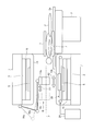
- FIG. 10 is a diagram illustrating an example of a moving mechanism of the PET detector according to the eighth embodiment. As shown in FIG. 10, the eighth embodiment includes a PET detector 13a, a PET detector 13b, and a PET detector 13c.
- the PET detectors 13a and 13b are formed in a ring shape and have a detection surface on the inner periphery of the ring.
- the PET detector 13a and the PET detector 13b are arranged side by side along the axis Z of the bore B.
- the PET detector 13a is moved in the axis Z direction of the bore B by the moving mechanism 20a (the direction of the double arrow A1 shown in FIG. 10), and the PET detector 13b is moved in the axis Z direction of the bore B by the moving mechanism 20b. (Direction of double-headed arrow A2 shown in FIG. 10).
- the PET detectors 13a and 13b are moved within the gantry by the moving mechanism 10a. Thereby, the space
- the PET detector 13c has a detection surface that is substantially perpendicular to the axis Z direction of the bore B.
- the PET detector 13c is moved along the axis Z direction of the bore B by the moving mechanism 20c (the direction of the double arrow A3 shown in FIG. 10).
- the PET detector 13c is also moved in the gantry by the moving mechanism 20c. Then, the moving mechanism 20c moves to the position adjacent to the PET detector 13a in the direction of the axis Z of the bore B.
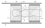
- FIGS. 11 and 12 are diagrams showing an example of an effective imaging area of the PET-MRI apparatus in the eighth embodiment.
- the PET detector and the bore cover 19 are shown, and the other components are not shown.
- FIG. 11 shows an effective imaging area when the PET detector 13c (not shown) is separated from the PET detector 13a.
- Each of the regions 33 formed between the inner peripheral surface of each of the two becomes an effective imaging region capable of capturing a PET image.
- a straight line 34 shown in FIG. 11 indicates the center position in the axial direction of the bore B, and the spherical area 35 is an effective imaging area of the MR image.
- FIG. 12 shows an effective imaging area when the PET detector 13c is adjacent to the PET detector 13a.
- the region 36 formed between the detection surface of the PET detector 13c and the inner peripheral surface of the PET detector 13a, and the PET detector 13c A region 37 formed between the detection surface and the inner peripheral surface of the PET detector 13b is an effective imaging region in which a PET image can be captured.
- the PET detector 13c adjacent to the PET detector 13a by making the PET detector 13c adjacent to the PET detector 13a, the detection probability of gamma rays emitted from the subject P inside the PET detector 13a can be improved. . Thereby, it becomes possible to improve the spatial resolution of the PET image inside the PET detector 13a.
- 11 and 12 show an example in which the head of the subject P is placed inside the PET detector 13a, but the same effect can be obtained when the foot of the subject P is placed. can get. That is, imaging with the PET detector 13c adjacent to the PET detector 13a is suitable for imaging the end of the subject P.
- the movement mechanism of the PET detector has been described.
- the position of the PET detector moved by the movement mechanism is detected, and the detected position of the PET detector is displayed on the display unit. May be.
- the computer 10 shown in FIG. 1 acquires the movement amount from a driving device that drives the movement mechanism, or detects the position of the PET detector by a position sensor provided in the PET detector. To do.
- the computer 10 causes the display 12 to display the detected position of the PET detector together with the PET image and the MR image.
- the computer 10 may display the position of the magnetic field center together.
- the moving mechanism is driven by the driving device.
- the moving mechanism may be manually operated by an operator.
- the arrangement of the PET detector and the configuration of the movement mechanism described in the above embodiment can be implemented in combination as appropriate.
- the PET detector 13 a arranged on the upper side of the bore B can be moved to the outside of the static magnetic field magnet 1. You may make it provide.
- the bore cover 19 is formed so as to protrude from the static magnetic field magnet 1 on the side where the bed 2 is not placed, and the moving mechanism 20 a is provided inside the protruding portion of the bore cover 19. It is provided so that it may extend into the space formed.
Landscapes
- Health & Medical Sciences (AREA)
- Life Sciences & Earth Sciences (AREA)
- Physics & Mathematics (AREA)
- Nuclear Medicine, Radiotherapy & Molecular Imaging (AREA)
- Engineering & Computer Science (AREA)
- General Health & Medical Sciences (AREA)
- Radiology & Medical Imaging (AREA)
- Molecular Biology (AREA)
- Medical Informatics (AREA)
- High Energy & Nuclear Physics (AREA)
- Biomedical Technology (AREA)
- Biophysics (AREA)
- Surgery (AREA)
- Public Health (AREA)
- Veterinary Medicine (AREA)
- Heart & Thoracic Surgery (AREA)
- Pathology (AREA)
- Animal Behavior & Ethology (AREA)
- General Physics & Mathematics (AREA)
- Condensed Matter Physics & Semiconductors (AREA)
- Pulmonology (AREA)
- Theoretical Computer Science (AREA)
- Spectroscopy & Molecular Physics (AREA)
- Optics & Photonics (AREA)
- Nuclear Medicine (AREA)
- Magnetic Resonance Imaging Apparatus (AREA)
Abstract
実施形態に係るPET-MRI装置(100)は、静磁場磁石(1)と、傾斜磁場コイル(3)と、高周波コイル(5)とを有する架台と、PET検出器(13、13a、13b、13c)と、移動機構(20、20a、20b、20c)とを備える。静磁場磁石(1)は、略円筒状のボア内に静磁場を発生させる。傾斜磁場コイル(3)は、前記静磁場磁石(1)の内周側に配置され、前記ボア内に配置された被検体に傾斜磁場を印加する。高周波コイル(5)は、前記傾斜磁場コイル(3)の内周側に配置され、前記被検体に高周波磁場を印加する。PET検出器(13、13a、13b、13c)は、前記被検体に投与された陽電子放出核種から放出されるガンマ線を検出する。移動機構(20、20a、20b、20c)は、前記架台内で前記ボアの軸方向に沿って前記PET検出器(13、13a、13b、13c)を移動させる。
Description
本発明の実施の形態は、PET(Positron Emission Tomography)-MRI(Magnetic Resonance Imaging)装置に関する。
近年、PET(Positron Emission Tomography)装置とMRI(Magnetic Resonance Imaging)装置とを組み合わせたPET-MRI装置の製品化が始められている。一般的に、PET-MRI装置は、MRI装置にPET検出器を装着することで実現されるが、PET検出器の位置は固定されている場合が多い。しかし、MRI装置の磁場中心付近にPET検出器が固定されると、磁場中心で発生される高電力RF(Radio Frequency)磁場や、発生する磁気共鳴信号を検出する高周波コイル(RFコイル)とPET検出器とが干渉することによって、適切にデータ収集が行われない場合もあり得る。
本発明が解決しようとする課題は、磁場中心で発生される高電力RF磁場や、発生する磁気共鳴信号を検出する高周波コイルとPET検出器とが干渉することよるデータ収集への影響を抑えることができるPET-MRI装置を提供することである。
実施形態に係るPET-MRI装置は、静磁場磁石と、傾斜磁場コイルと、高周波コイルとを有する架台と、PET検出器と、移動機構とを備える。静磁場磁石は、略円筒状のボア内に静磁場を発生させる。傾斜磁場コイルは、前記静磁場磁石の内周側に配置され、前記ボア内に配置された被検体に傾斜磁場を印加する。高周波コイルは、前記傾斜磁場コイルの内周側に配置され、前記被検体に高周波磁場を印加する。PET検出器は、前記被検体に投与された陽電子放出核種から放出されるガンマ線を検出する。移動機構は、前記架台内で前記ボアの軸方向に沿って前記PET検出器を移動させる。
以下、図面を参照して、PET-MRI装置の実施形態を説明する。
(第1の実施形態)
図1は、第1の実施形態に係るPET-MRI装置の全体構成を示す図である。図1に示すように、第1の実施形態に係るPET-MRI装置100は、静磁場磁石1と、寝台2と、傾斜磁場コイル3と、傾斜磁場コイル駆動回路4と、送信用高周波コイル5と、送信部6と、受信用高周波コイル7と、受信部8と、MRデータ収集部9と、計算機10と、コンソール11と、ディスプレイ12と、PET検出器13と、信号線14と、PETデータ収集部15と、PET画像再構成部16と、シーケンスコントローラ17と、高周波シールド18と、ボアカバー19とを備える。
図1は、第1の実施形態に係るPET-MRI装置の全体構成を示す図である。図1に示すように、第1の実施形態に係るPET-MRI装置100は、静磁場磁石1と、寝台2と、傾斜磁場コイル3と、傾斜磁場コイル駆動回路4と、送信用高周波コイル5と、送信部6と、受信用高周波コイル7と、受信部8と、MRデータ収集部9と、計算機10と、コンソール11と、ディスプレイ12と、PET検出器13と、信号線14と、PETデータ収集部15と、PET画像再構成部16と、シーケンスコントローラ17と、高周波シールド18と、ボアカバー19とを備える。
静磁場磁石1は、略円筒状のボアB内に静磁場を発生させる。寝台2は、被検体Pが載せられる天板2aを有する。この寝台2は、撮像時には、ボアBの軸方向に沿って天板2aを長手方向にボアB内へ移動させることで、被検体Pを静磁場内へ移動する。
傾斜磁場コイル3は、被検体Pに対して、磁場強度がX,Y,Z方向に直線的に変化する傾斜磁場Gx,Gy,Gzを印加する。この傾斜磁場コイル3は、略円筒状に形成され、静磁場磁石1の内周側に配置される。傾斜磁場コイル駆動回路4は、シーケンスコントローラ17による制御のもと、傾斜磁場コイル3を駆動する。
送信用高周波コイル5は、送信部6から送信される高周波パルスに基づいて、静磁場内に置かれた被検体Pに高周波磁場を印加する。この送信用高周波コイル5は、略円筒状に形成され、傾斜磁場コイル3の内周側に配置される。送信部6は、シーケンスコントローラ17による制御のもと、送信用高周波コイル5に高周波パルスを送信する。
受信用高周波コイル7は、高周波磁場及び傾斜磁場の印加により被検体Pから発せられる磁気共鳴信号を検出する。例えば、受信用高周波コイル7は、撮像対象の部位に応じて被検体Pの表面に配置される表面コイルである。例えば、被検体Pの体部が撮像される場合には、2つの受信用高周波コイル7が被検体Pの上部及び下部に配置される。受信部8は、シーケンスコントローラ17による制御のもと、受信用高周波コイル7によって検出された磁気共鳴信号を受信し、受信した磁気共鳴信号をMRデータ収集部9に送る。
MRデータ収集部9は、シーケンスコントローラ17による制御のもと、受信部8から送られた磁気共鳴信号を収集する。そして、MRデータ収集部9は、収集した磁気共鳴信号を増幅及び検波した後にA/D変換し、計算機10に送る。計算機10は、コンソール11により制御され、MRデータ収集部9から送られた磁気共鳴信号に基づいてMR画像を再構成する。そして、計算機10は、再構成したMR画像をディスプレイ12に表示させる。
PET検出器13は、被検体Pに投与された陽電子放出核種から放出されるガンマ線(消滅放射線を含む)を計数情報として検出する。このPET検出器13は、リング状に形成され、送信用高周波コイル5の外周側に配置される。例えば、PET検出器13は、シンチレータと光検出器とを有する検出器モジュールをリング状に配置することで形成される。ここで、シンチレータは、例えば、LYSO(Lutetium Yttrium Oxyorthosilicate)、LSO(Lutetium Oxyorthosilicate)、LGSO(Lutetium Gadolinium Oxyorthosilicate)などである。また、光検出器は、例えば、APD(Avalanche Photodiode)素子やSiPM(Silicon Photomultiplier)などの半導体検出器や、光電子増倍管(Photomultiplier Tube:PMT)である。そして、PET検出器13は、検出した計数情報を、信号線14を介してPETデータ収集部15に送る。
PETデータ収集部15は、シーケンスコントローラ17による制御のもと、同時計数情報を生成する。このPETデータ収集部15は、PET検出器13によって検出されたガンマ線の計数情報を用いて、陽電子放出核種から放出されたガンマ線を略同時に検出した計数情報の組み合わせを同時計数情報として生成する。
PET画像再構成部16は、PETデータ収集部15により生成された同時計数情報を投影データとしてPET画像を再構成する。このPET画像再構成部16によって再構成されたPET画像は、計算機10に送信されてディスプレイ12に表示される。シーケンスコントローラ17は、撮像時に実行される各種撮像シーケンス情報を計算機10より受け取り、上述した各部を制御する。
高周波シールド18は、傾斜磁場コイル3と送信用高周波コイル5との間に配置され、送信用高周波コイル5により発生する高周波磁場を遮蔽する。ボアカバー19は、送信用高周波コイル5の内周側を覆うカバーである。このボアカバー19によって、静磁場磁石1、傾斜磁場コイル3、高周波シールド18及び送信用高周波コイル5によって構成される概略円筒形状の構造体の内側に、略円筒状の空間であるボアBが形成される。
そして、第1の実施形態に係るPET-MRI装置100は、上記構成に加えて、ボアの軸方向に沿ってPET検出器13を移動させる移動機構20をさらに備える。
図2は、第1の実施形態に係るPET検出器の移動機構の一例を示す図である。図2に示すように、第1の実施形態では、PET検出器13は、送信用高周波コイル5とボアカバー19との間に配置される。また、移動機構20も、送信用高周波コイル5とボアカバー19との間に配置される。
そして、図2に示すように、移動機構20は、架台内でボアの軸方向に沿ってPET検出器13を移動させる。例えば、移動機構20は、高周波コイル5とボアカバー19との間に形成されている空間内で、ボアBの軸Z方向にPET検出器13を移動させる(図2に示す両矢印Aの方向)。この移動機構20は、例えば、駆動装置21によって駆動されることで、PET検出器13を移動させる。
例えば、移動機構20は、ボアBの軸方向に沿って、静磁場磁石1や傾斜磁場コイル3、送信用高周波コイル5、ボアカバー19などから構成される架台の端部に配置された少なくとも2つの回転軸と、これらの回転軸に架け渡されたベルトとから構成される。そして、駆動装置21が回転軸を回転駆動させることで、ベルトの一部に固定されたPET検出器13がボアBのZ軸方向に移動される。
以上、第1の実施形態に係るPET-MRI装置について説明した。近年、製品化が始められているPET-MRI装置では、PET検出器の位置が固定されている場合が多い。PET検出器が取り外し可能なPET-MRI装置もあるが、そのような場合でもPET検出器の位置は固定されていることが多い。また、間隔を開けて2つのPET検出器を配置したPET-MRI装置も提案されているが、PET検出器は必ずしも撮影中心の周りに配置される必要はなく、多少ずれていてもよい。
実際に、PET検出器と高周波コイルとはボアの軸方向の位置がずれていた方が干渉しにくく互いのデータ収集に好適である。また、MRIによる撮像はボアの軸方向における中心位置に限られるが、PETによる撮像はボアの軸方向のどこでも実施可能である。また、MRIによる撮像とPETによる撮像とは、互いにデータの収集時間が異なるため、PETによる撮像の対象位置が常に磁場中心であることは、MRIとPETとを組み合わせた撮像プロトコルを構築するうえで不便な場合がある。
これに対し、第1の実施形態に係るPET-MRI装置100では、移動機構20によってPET検出器13をボアの軸方向に移動させることで、PET検出器13を磁場中心から離れた位置へ移動することができる。これにより、PET検出器と磁場との干渉によるデータ収集への影響を抑えることができる。また、MRIとPETとを組み合わせた撮像プロトコルを構築するうえでの自由度を増やすことができる。
なお、PET検出器の移動機構は、図2に示した例に限られるものではない。そこで、以下では、第2~第8の実施形態として、移動機構の他の例について説明する。
(第2の実施形態)
図3は、第2の実施形態に係るPET検出器の移動機構の一例を示す図である。図3に示すように、第2の実施形態では、PET検出器13は、傾斜磁場コイル3と高周波シールド18との間に配置される。また、移動機構20も、傾斜磁場コイル3と高周波シールド18との間に配置される。そして、図3に示すように、移動機構20は、架台内でボアの軸方向に沿ってPET検出器13を移動させる。例えば、移動機構20は、駆動装置21によって駆動されて、傾斜磁場コイル3と高周波シールド18との間に形成されている空間内で、ボアの軸Z方向にPET検出器13を移動させる(図3に示す両矢印Aの方向)。
図3は、第2の実施形態に係るPET検出器の移動機構の一例を示す図である。図3に示すように、第2の実施形態では、PET検出器13は、傾斜磁場コイル3と高周波シールド18との間に配置される。また、移動機構20も、傾斜磁場コイル3と高周波シールド18との間に配置される。そして、図3に示すように、移動機構20は、架台内でボアの軸方向に沿ってPET検出器13を移動させる。例えば、移動機構20は、駆動装置21によって駆動されて、傾斜磁場コイル3と高周波シールド18との間に形成されている空間内で、ボアの軸Z方向にPET検出器13を移動させる(図3に示す両矢印Aの方向)。
(第3の実施形態)
図4は、第3の実施形態に係るPET検出器の移動機構の一例を示す図である。図4に示すように、第3の実施形態では、天板が、被検体Pが載せられる天板2aと、天板2aを下方から支持する天板2bとに分けられる。天板2aは、天板2bとの間で相対的な位置が変わらないように、天板2b上に置かれる。そして、寝台2が、天板2b上に天板2aが載せられた状態で天板2bをボアB内へ移動させる(図4に示す両矢印A1の方向)。
図4は、第3の実施形態に係るPET検出器の移動機構の一例を示す図である。図4に示すように、第3の実施形態では、天板が、被検体Pが載せられる天板2aと、天板2aを下方から支持する天板2bとに分けられる。天板2aは、天板2bとの間で相対的な位置が変わらないように、天板2b上に置かれる。そして、寝台2が、天板2b上に天板2aが載せられた状態で天板2bをボアB内へ移動させる(図4に示す両矢印A1の方向)。
そして、PET検出器13は、天板に、当該天板の長手方向へ移動可能に設けられる。例えば、PET検出器13は、天板2b上に天板2bの長手方向に沿って形成された溝に配置され、天板2bの長手方向へ移動可能に支持される。また、移動機構20は、天板内に設けられる。そして、移動機構20は、例えば、駆動装置21によって駆動されて、PET検出器13を天板2bの長手方向へ移動させる(図4に示す両矢印A2の方向)。
すなわち、第3の実施形態では、PET検出器13は、天板2bの移動とともにボアBの軸Z方向へ移動させることもできるし、天板2bの位置が固定された場合でも、天板2bの長手方向に沿って、ボアBの軸Z方向へ移動することもできる。なお、PET検出器13は、天板2bに対して着脱可能に設けられてもよい。その場合には、例えば、PET検出器13の制御線や電源線を接続するためのコネクタは、天板2bに配置される。
(第4の実施形態)
図5及び6は、第4の実施形態に係るPET検出器の移動機構の一例を示す図である。図5に示すように、第4の実施形態では、第3の実施形態と同様に、天板が、被検体Pが載せられる天板2aと、天板2aが載せられる天板2bとに分けられる。天板2aと天板2bとの位置関係、寝台2の動作は、第3の実施形態と同様である。
図5及び6は、第4の実施形態に係るPET検出器の移動機構の一例を示す図である。図5に示すように、第4の実施形態では、第3の実施形態と同様に、天板が、被検体Pが載せられる天板2aと、天板2aが載せられる天板2bとに分けられる。天板2aと天板2bとの位置関係、寝台2の動作は、第3の実施形態と同様である。
そして、PET検出器は、第1のPET検出器13aと第2のPET検出器13bとに分割されている。そして、第1のPET検出器13aは、ボアBの周囲に配置され、第2のPET検出器13bは、天板に配置される。また、移動機構も、第1の移動機構20aと第2の移動機構20bとに分けられる。そして、図5に示すように、第1の移動機構20aは、架台内でボアの軸方向に沿ってPET検出器13aを移動させる。例えば、第1の移動機構20aは、駆動装置21aによって駆動されて、ボアBの周囲で、第1のPET検出器13aをボアBの軸Z方向に沿って移動させる(図5に示す両矢印A1の方向)。また、第2の移動機構20bは、例えば、駆動装置21bによって駆動されて、第2のPET検出器13bを天板2bの長手方向に沿って移動させる(図5に示す両矢印A2の方向)。
図6は、PET検出器13a及び13bとその周辺をボアBの軸方向Zからみた様子を示している。図6に示すように、PET検出器13a及び13bは、それぞれ円弧状に形成されている。そして、PET検出器13aは、円弧の内周側をボアB側に向けて、ボアBの上側に配置される。また、PET検出器13bは、円弧の内周側をボアB側に向けて、天板2b上に配置される。
すなわち、第4の実施形態では、PET検出器が、架台側に設けられたPET検出器13aと天板側に設けられたPET検出器13bとに分けられており、それぞれを独立して、ボアBの軸Z方向へ移動させることができる。そして、ボアB内に天板2bが挿入され、ボアBの軸Z方向で第1のPET検出器13aの位置と第2のPET検出器13bの位置とが合ったところで、データ収集が行われる。
なお、PET検出器13bは、天板2bに対して着脱可能に設けられてもよい。その場合には、例えば、PET検出器13bの制御線や電源線を接続するためのコネクタは、天板2bに配置される。また、第1のPET検出器13aは、少なくとも被検体Pを挿入している間は移動することができないように制御されてもよい。
(第5の実施形態)
図7は、第5の実施形態に係るPET検出器の移動機構の一例を示す図である。図7に示すように、第5の実施形態では、図5に示した第1の移動機構20aが、第1のPET検出器13aを上下動機構20dを介して上下方向へさらに移動させる(図7に示す両矢印Aの方向)。また、図7に示すように、第1の移動機構20aは、架台内でボアの軸方向に沿ってPET検出器13aを移動させる。
図7は、第5の実施形態に係るPET検出器の移動機構の一例を示す図である。図7に示すように、第5の実施形態では、図5に示した第1の移動機構20aが、第1のPET検出器13aを上下動機構20dを介して上下方向へさらに移動させる(図7に示す両矢印Aの方向)。また、図7に示すように、第1の移動機構20aは、架台内でボアの軸方向に沿ってPET検出器13aを移動させる。
すなわち、第5の実施形態では、PET検出器13aを、ボアBの軸Z方向だけでなく、上下方向へも移動することができる。これにより、例えば、被検体Pの体格の大きさに応じて、2つのPET検出器の間の距離を調整することができる。
(第6の実施形態)
図8は、第6の実施形態に係るPET検出器の移動機構の一例を示す図である。図8に示すように、第6の実施形態では、PET検出器13は、静磁場磁石1の外側へ移動可能に設けられる。例えば、図8に示すように、ボアカバー19が、寝台2が置かれていない側に静磁場磁石1から突出するように形成される。
図8は、第6の実施形態に係るPET検出器の移動機構の一例を示す図である。図8に示すように、第6の実施形態では、PET検出器13は、静磁場磁石1の外側へ移動可能に設けられる。例えば、図8に示すように、ボアカバー19が、寝台2が置かれていない側に静磁場磁石1から突出するように形成される。
そして、移動機構20が、ボアカバー19の突出部の内側に形成された空間に延びるように設けられる。そして、移動機構20は、ボアBの軸Z方向に沿ってPET検出器13を移動させる(図8に示す両矢印Aの方向)。また、図8に示すように、移動機構20は、架台内でボアの軸方向に沿ってPET検出器13を移動させる。これにより、移動機構20は、ボアカバー19の静磁場磁石1から突出した部分の内側にPET検出器13を移動させることで、PET検出器13を静磁場磁石1の外側へ移動することができる。
すなわち、第6の実施形態では、静磁場磁石1の外側へPET検出器13を移動させることができるので、PET検出器13と磁場との干渉によるデータ収集への影響をより確実に抑えることができる。
(第7の実施形態)
図9は、第7の実施形態に係るPET検出器の移動機構の一例を示す図である。図9に示すように、第7の実施形態では、PET検出器が、第1のPET検出器13aと第2のPET検出器13bとに分割されている。そして、第1のPET検出器13a及び第2のPET検出器13bは、ボアBの軸Zを挟んで対向して配置される。
図9は、第7の実施形態に係るPET検出器の移動機構の一例を示す図である。図9に示すように、第7の実施形態では、PET検出器が、第1のPET検出器13aと第2のPET検出器13bとに分割されている。そして、第1のPET検出器13a及び第2のPET検出器13bは、ボアBの軸Zを挟んで対向して配置される。
例えば、図9に示すように、第1のPET検出器13aをボアB内で移動可能に保持する保持部30aが設けられる。そして、図9に示すように、保持部30aは、架台内でボアの軸方向に沿ってPET検出器13aを移動させる。例えば、保持部30aは、ボアBの軸Z方向に沿ってPET検出器13aを移動させる(図9に示す両矢印A1の方向)。例えば、保持部30aは、複数の間接部を有するアームを用いることにより実現される。この保持部30aは、駆動装置によって駆動されることでPET検出器13aを移動させてもよいし、操作者による手動の操作によってPET検出器13aを移動させてもよい。
そして、図9に示すように、移動機構20が、架台内でボアの軸方向に沿ってPET検出器13bを移動させる。例えば、移動機構20は、第1のPET検出器13aの移動に連動して、第2のPET検出器13bをボアBの軸Z方向に沿って移動させる(図9に示す両矢印A2の方向)。ここで、第2の検出器13bは、ボアBの軸Z方向に第1のPET検出器13aよりも大きな幅を有する。第2の検出器13bのボアBの軸Z方向の幅を十分に大きくした場合には、第2の検出器13bの位置を固定して、移動機構20を不要とすることもできる。
(第8の実施形態)
図10は、第8の実施形態に係るPET検出器の移動機構の一例を示す図である。図10に示すように、第8の実施形態では、PET検出器13aと、PET検出器13bと、PET検出器13cとを備える。
図10は、第8の実施形態に係るPET検出器の移動機構の一例を示す図である。図10に示すように、第8の実施形態では、PET検出器13aと、PET検出器13bと、PET検出器13cとを備える。
PET検出器13a及び13bは、リング状に形成され、リング内周に検出面を有する。PET検出器13aとPET検出器13bとは、ボアBの軸Zに沿って並べて配置される。PET検出器13aは、移動機構20aによってボアBの軸Z方向に移動され(図10に示す両矢印A1の方向)、PET検出器13bは、移動機構20bによってボアBの軸Z方向に移動される(図10に示す両矢印A2の方向)。なお、図10に示すように、PET検出器13a及び13bは、移動機構10aによって架台内で移動される。これにより、PET検出器13aとPET検出器13bとの間隔が、任意に調整される。
また、PET検出器13cは、ボアBの軸Z方向に略垂直な検出面を有する。PET検出器13cは、移動機構20cによって、ボアBの軸Z方向に沿って移動される(図10に示す両矢印A3の方向)。なお、図10に示すように、PET検出器13cも、移動機構20cによって架台内で移動される。そして、移動機構20cは、ボアBの軸Z方向でPET検出器13aに隣接する位置に移動させる。
図11及び12は、第8の実施形態におけるPET-MRI装置の有効撮像領域の一例を示す図である。なお、図11及び12では、PET検出器とボアカバー19とを示し、他の構成要素については図示を省略している。
図11は、PET検出器13c(図示せず)をPET検出器13aから離した場合の有効撮像領域を示している。この場合には、PET検出器13aの内周面で囲まれた領域31と、PET検出器13bの内周面で囲まれた領域32と、PET検出器13aの内周面とPET検出器13bの内周面との間に形成される領域33とが、それぞれPET画像を撮像可能な有効撮像領域となる。なお、図11に示す直線34は、ボアBの軸方向における中央の位置を示しており、球状の領域35は、MR画像の有効撮像領域である。
図12は、PET検出器13cをPET検出器13aに隣接させた場合の有効撮像領域を示している。この場合には、図11に示した領域31~33に加えて、PET検出器13cの検出面とPET検出器13aの内周面との間に形成される領域36と、PET検出器13cの検出面とPET検出器13bの内周面との間に形成される領域37とが、さらにPET画像を撮像可能な有効撮像領域となる。
図11及び12からも明らかなように、PET検出器13cをPET検出器13aに隣接させることで、PET検出器13aの内側で被検体Pから放出されるガンマ線の検出確率を向上させることができる。これにより、PET検出器13aの内側におけるPET画像の空間分解能を向上させることが可能になる。なお、図11及び12では、PET検出器13aの内側に被検体Pの頭部を配置させた場合の例を示しているが、被検体Pの足部を配置させた場合も同様の効果が得られる。すなわち、PET検出器13cをPET検出器13aに隣接させた撮像は、被検体Pの端部を撮像する場合に好適である。
なお、上記実施形態では、PET検出器の移動機構について説明したが、例えば、移動機構によって移動されたPET検出器の位置を検出し、検出したPET検出器の位置を表示部に表示するようにしてもよい。その場合には、例えば、図1に示した計算機10が、移動機構を駆動させる駆動装置から移動量を取得したり、PET検出器に設けられた位置センサによってPET検出器の位置を検出したりする。そして、計算機10が、例えば、検出したPET検出器の位置を、PET画像やMR画像とともにディスプレイ12に表示させる。このとき、計算機10は、磁場中心の位置を一緒に表示させてもよい。
また、上記実施形態では、駆動装置によって移動機構を駆動させる例について説明したが、例えば、移動機構は、操作者によって手動で操作されてもよい。
また、上記実施形態で説明したPET検出器の配置や移動機構の構成は、それぞれ適宜に組み合わせて実施することも可能である。例えば、図5に示した第4の実施形態に図8に示した第6の実施形態を組み合わせて、ボアBの上側に配置されたPET検出器13aを静磁場磁石1の外側へ移動可能に設けるようにしてもよい。その場合には、図8に示したように、ボアカバー19が、寝台2が置かれていない側に静磁場磁石1から突出するように形成され、移動機構20aが、ボアカバー19の突出部の内側に形成された空間に延びるように設けられる。
以上説明した各実施形態によれば、PET検出器と磁場との干渉によるデータ収集への影響を抑えることができる。
本発明のいくつかの実施形態を説明したが、これらの実施形態は、例として提示したものであり、発明の範囲を限定することは意図していない。これら実施形態は、その他の様々な形態で実施されることが可能であり、発明の要旨を逸脱しない範囲で、種々の省略、置き換え、変更を行うことができる。これら実施形態やその変形は、発明の範囲や要旨に含まれると同様に、請求の範囲に記載された発明とその均等の範囲に含まれるものである。
Claims (11)
- 略円筒状のボア内に静磁場を発生させる静磁場磁石と、
前記静磁場磁石の内周側に配置され、前記ボア内に配置された被検体に傾斜磁場を印加する傾斜磁場コイルと、
前記傾斜磁場コイルの内周側に配置され、前記被検体に高周波磁場を印加する高周波コイルと
を有する架台と、
前記被検体に投与された陽電子放出核種から放出されるガンマ線を検出するPET検出器と、
前記架台内で前記ボアの軸方向に沿って前記PET検出器を移動させる移動機構と
を備える、PET-MRI装置。 - 前記高周波コイルの内周側を覆うボアカバーをさらに備え、
前記PET検出器は、前記高周波コイルと前記ボアカバーとの間に配置される、
請求項1に記載のPET-MRI装置。 - 前記傾斜磁場コイルと前記高周波コイルとの間に配置され、前記高周波コイルにより発生する高周波磁場を遮蔽する高周波シールドをさらに備え、
前記PET検出器は、前記傾斜磁場コイルと前記高周波シールドとの間に配置される、
請求項1に記載のPET-MRI装置。 - 前記PET検出器を第1のPET検出器として備え、
前記移動機構を第1の移動機構として備え、
前記被検体が載置される天板と、
前記ボアの軸方向に沿って前記天板を長手方向に前記ボア内へ移動させる寝台と、
前記天板に当該天板の長手方向へ移動可能に設けられた第2のPET検出器と、
前記第2のPET検出器を前記天板の長手方向へ移動させる第2の移動機構と
をさらに備える、
請求項1に記載のPET-MRI装置。 - 前記被検体が載置される天板と、
前記ボアの軸方向に沿って前記天板を長手方向に前記ボア内へ移動させる寝台とをさらに備え、
前記PET検出器は、第1のPET検出器と第2のPET検出器とに分割されており、
前記第1のPET検出器は、前記ボアの周囲に配置され、
前記第2のPET検出器は、前記天板に配置され、
前記移動機構は、前記第1のPET検出器と前記第2のPET検出器とをそれぞれ独立して移動させる、
請求項1に記載のPET-MRI装置。 - 前記第1のPET検出器を前記ボア内で移動可能に保持する保持部をさらに備え、
前記移動機構は、前記第1のPET検出器の移動に連動して前記第2のPET検出器を前記ボアの軸方向に沿って移動させる、
請求項4又は5に記載のPET-MRI装置。 - 前記第2のPET検出器は、前記ボアの軸方向に前記第1のPET検出器よりも大きな幅を有する、
請求項4又は5に記載のPET-MRI装置。 - 前記PET検出器は、
リング状に形成され、リング内周に検出面を有する第1のPET検出器と、
前記ボアの軸方向に略垂直な検出面を有する第2のPET検出器とを含み、
前記移動機構は、前記ボアの軸方向で前記第1のPET検出器に隣接する位置に前記第2のPET検出器を移動させる、
請求項1に記載のPET-MRI装置。 - 前記PET検出器の位置を検出する位置検出部と、
前記PET検出器によって検出された前記PET検出器の位置を表示する表示部と
をさらに備える、
請求項1~8のいずれか一つに記載のPET-MRI装置。 - 前記PET検出器は、前記静磁場磁石の外側へ移動可能に設けられる、
請求項1~9のいずれか一つに記載のPET-MRI装置。 - 前記移動機構は、前記PET検出器を上下方向へさらに移動させる、
請求項1~10のいずれか一つに記載のPET-MRI装置。
Priority Applications (3)
| Application Number | Priority Date | Filing Date | Title |
|---|---|---|---|
| EP13781234.3A EP2843443B1 (en) | 2012-04-24 | 2013-04-24 | Pet-mri device |
| CN201380001689.3A CN103608698A (zh) | 2012-04-24 | 2013-04-24 | Pet-mri装置 |
| US14/522,024 US10067207B2 (en) | 2012-04-24 | 2014-10-23 | PET-MRI apparatus |
Applications Claiming Priority (2)
| Application Number | Priority Date | Filing Date | Title |
|---|---|---|---|
| JP2012099058A JP2013228226A (ja) | 2012-04-24 | 2012-04-24 | Pet−mri装置 |
| JP2012-099058 | 2012-04-24 |
Related Child Applications (1)
| Application Number | Title | Priority Date | Filing Date |
|---|---|---|---|
| US14/522,024 Continuation US10067207B2 (en) | 2012-04-24 | 2014-10-23 | PET-MRI apparatus |
Publications (1)
| Publication Number | Publication Date |
|---|---|
| WO2013161908A1 true WO2013161908A1 (ja) | 2013-10-31 |
Family
ID=49483216
Family Applications (1)
| Application Number | Title | Priority Date | Filing Date |
|---|---|---|---|
| PCT/JP2013/062131 Ceased WO2013161908A1 (ja) | 2012-04-24 | 2013-04-24 | Pet-mri装置 |
Country Status (5)
| Country | Link |
|---|---|
| US (1) | US10067207B2 (ja) |
| EP (1) | EP2843443B1 (ja) |
| JP (1) | JP2013228226A (ja) |
| CN (1) | CN103608698A (ja) |
| WO (1) | WO2013161908A1 (ja) |
Cited By (2)
| Publication number | Priority date | Publication date | Assignee | Title |
|---|---|---|---|---|
| KR101497317B1 (ko) * | 2013-11-27 | 2015-03-02 | 네이버 주식회사 | 클라우드 기반 개인화 데이터 검색 시스템 및 그 방법 |
| KR101497313B1 (ko) * | 2013-11-27 | 2015-03-02 | 네이버 주식회사 | 클라우드 디스크 기반 개인화 데이터 검색 시스템 및 그 방법 |
Families Citing this family (10)
| Publication number | Priority date | Publication date | Assignee | Title |
|---|---|---|---|---|
| DE102015200510A1 (de) * | 2015-01-15 | 2016-07-21 | Siemens Healthcare Gmbh | Bewegungssensor |
| US10539639B2 (en) | 2015-08-06 | 2020-01-21 | Synaptive Medical (Barbados) Inc. | Local active gradient shielding |
| JP6890606B2 (ja) * | 2016-03-03 | 2021-06-18 | コーニンクレッカ フィリップス エヌ ヴェKoninklijke Philips N.V. | ハイブリッドx線及びガンマ線撮像システム |
| US10018696B2 (en) | 2016-07-11 | 2018-07-10 | Siemens Medical Solutions Usa, Inc. | Magnetic lensing for beta emission imaging |
| CN106510745B (zh) | 2016-09-23 | 2021-06-01 | 东软医疗系统股份有限公司 | Pet和ct/mri机械联动系统及其联动扫描方法 |
| US11090012B2 (en) | 2019-01-29 | 2021-08-17 | Shanghai United Imaging Healthcare Co., Ltd. | Positron emission tomography-magnetic resonance imaging apparatus |
| WO2021060286A1 (ja) * | 2019-09-24 | 2021-04-01 | 国立研究開発法人量子科学技術研究開発機構 | 放射線画像化ユニット及び放射線検出器モジュール |
| WO2022055540A1 (en) * | 2020-09-11 | 2022-03-17 | Siemens Medical Solutions Usa, Inc. | Arrangement of pet detectors for combined pet/mr systems |
| US11402451B2 (en) * | 2020-09-24 | 2022-08-02 | Siemens Medical Solutions Usa, Inc. | Timing signal distribution to pet imaging components via optical path |
| US20230371840A1 (en) * | 2020-09-27 | 2023-11-23 | Sino Canada Health Engineering Research Institute (Hefei) Ltd. | Imaging plug-in device |
Citations (6)
| Publication number | Priority date | Publication date | Assignee | Title |
|---|---|---|---|---|
| JP2004350942A (ja) * | 2003-05-29 | 2004-12-16 | Hitachi Ltd | 断層像作成装置及び放射線検査装置 |
| JP2008525161A (ja) | 2004-12-29 | 2008-07-17 | シーメンス メディカル ソリューションズ ユーエスエー インコーポレイテッド | 陽電子放出断層撮影−磁気共鳴断層撮影複合撮像システム及び陽電子放出断層撮影−磁気共鳴断層撮影の同時撮像に用いられるアバランシェフォトダイオードベースの陽電子放出断層撮影検出器 |
| JP2009540882A (ja) * | 2006-06-20 | 2009-11-26 | イムリス インコーポレイテッド | 診察及び外科イメージング用の回転式統合型スキャナー |
| JP2011030682A (ja) * | 2009-07-31 | 2011-02-17 | Hitachi Ltd | Mri−pet装置 |
| JP2011514518A (ja) * | 2008-02-25 | 2011-05-06 | コーニンクレッカ フィリップス エレクトロニクス エヌ ヴィ | 放射線検出器に対する等角面のバックボーン |
| JP2011185796A (ja) * | 2010-03-09 | 2011-09-22 | Natl Inst Of Radiological Sciences | Pet/mri装置、pet装置及び画像再構成システム |
Family Cites Families (23)
| Publication number | Priority date | Publication date | Assignee | Title |
|---|---|---|---|---|
| EP1328189B1 (en) * | 2000-05-16 | 2016-08-24 | Dario B. Crosetto | Apparatus for anatomical and functional medical imaging |
| EP1347309A3 (en) * | 2002-03-20 | 2012-04-18 | Hitachi, Ltd. | Radiological imaging apparatus and method |
| US6917666B2 (en) * | 2002-12-19 | 2005-07-12 | General Electric Company | System and method for table/gantry alignment in imaging systems |
| CN101132731A (zh) * | 2004-12-29 | 2008-02-27 | 美国西门子医疗解决公司 | 用于pet/mr同时成像的组合式pet/mr成像系统和基于apd的pet探测器 |
| US7750311B2 (en) * | 2005-02-25 | 2010-07-06 | Intramedical Imaging, Llc | Positron emission detectors and configurations |
| JP4786213B2 (ja) * | 2005-03-30 | 2011-10-05 | 株式会社東芝 | 寝台装置及びmri装置 |
| US20070143921A1 (en) * | 2005-12-27 | 2007-06-28 | Kabushiki Kaisha Toshiba | Bed apparatus and MRI apparatus |
| US7847549B2 (en) * | 2006-01-05 | 2010-12-07 | Hitachi Medical Corporation | Magnetic resonance imaging apparatus |
| US20080146914A1 (en) | 2006-12-19 | 2008-06-19 | General Electric Company | System, method and apparatus for cancer imaging |
| DE102007009184B4 (de) * | 2007-02-26 | 2017-03-23 | Siemens Healthcare Gmbh | Vorrichtung zur überlagerten MRI- und PET-Bilddarstellung |
| US20080267358A1 (en) * | 2007-04-27 | 2008-10-30 | Yoichi Hiyama | Patient couch apparatus, diagnostic imaging apparatus, and method of operating patient couch apparatus |
| KR100891056B1 (ko) * | 2007-05-31 | 2009-03-31 | 이재성 | 개방형 pet-mri통합 유닛 |
| KR100891057B1 (ko) * | 2007-05-31 | 2009-03-31 | 이재성 | 탈장착형 pet-mri통합 유닛 |
| US8525116B2 (en) * | 2007-07-25 | 2013-09-03 | Koninklijke Philips N.V. | MR/PET imaging systems |
| DE102008012312B4 (de) * | 2008-03-03 | 2011-09-22 | Siemens Aktiengesellschaft | Magnetresonanzgerät mit einer PET-Einheit |
| JP4771490B2 (ja) * | 2008-10-03 | 2011-09-14 | 学校法人東海大学 | 磁気共鳴イメージング装置 |
| US8084741B2 (en) * | 2009-10-01 | 2011-12-27 | Kabushiki Kaisha Toshiba | Configurable coincidence pairing and filtering system and method for positron emission tomography |
| WO2011125212A1 (ja) * | 2010-04-08 | 2011-10-13 | 独立行政法人放射線医学総合研究所 | 近接撮影型pet装置およびシステム |
| JP5750684B2 (ja) | 2010-11-01 | 2015-07-22 | 国立研究開発法人放射線医学総合研究所 | Pet−mri装置 |
| JP5789861B2 (ja) * | 2010-11-01 | 2015-10-07 | 国立研究開発法人放射線医学総合研究所 | Pet−mri装置 |
| CN102686155B (zh) | 2011-01-06 | 2015-04-22 | 株式会社东芝 | Pet-mri装置 |
| JP5750685B2 (ja) | 2011-01-11 | 2015-07-22 | 国立研究開発法人放射線医学総合研究所 | Pet装置及びpet−mri装置 |
| US9386941B2 (en) * | 2013-07-02 | 2016-07-12 | MRI International, Inc. | Table stabilizers for scanner systems |
-
2012
- 2012-04-24 JP JP2012099058A patent/JP2013228226A/ja active Pending
-
2013
- 2013-04-24 CN CN201380001689.3A patent/CN103608698A/zh active Pending
- 2013-04-24 WO PCT/JP2013/062131 patent/WO2013161908A1/ja not_active Ceased
- 2013-04-24 EP EP13781234.3A patent/EP2843443B1/en active Active
-
2014
- 2014-10-23 US US14/522,024 patent/US10067207B2/en active Active
Patent Citations (6)
| Publication number | Priority date | Publication date | Assignee | Title |
|---|---|---|---|---|
| JP2004350942A (ja) * | 2003-05-29 | 2004-12-16 | Hitachi Ltd | 断層像作成装置及び放射線検査装置 |
| JP2008525161A (ja) | 2004-12-29 | 2008-07-17 | シーメンス メディカル ソリューションズ ユーエスエー インコーポレイテッド | 陽電子放出断層撮影−磁気共鳴断層撮影複合撮像システム及び陽電子放出断層撮影−磁気共鳴断層撮影の同時撮像に用いられるアバランシェフォトダイオードベースの陽電子放出断層撮影検出器 |
| JP2009540882A (ja) * | 2006-06-20 | 2009-11-26 | イムリス インコーポレイテッド | 診察及び外科イメージング用の回転式統合型スキャナー |
| JP2011514518A (ja) * | 2008-02-25 | 2011-05-06 | コーニンクレッカ フィリップス エレクトロニクス エヌ ヴィ | 放射線検出器に対する等角面のバックボーン |
| JP2011030682A (ja) * | 2009-07-31 | 2011-02-17 | Hitachi Ltd | Mri−pet装置 |
| JP2011185796A (ja) * | 2010-03-09 | 2011-09-22 | Natl Inst Of Radiological Sciences | Pet/mri装置、pet装置及び画像再構成システム |
Non-Patent Citations (1)
| Title |
|---|
| See also references of EP2843443A4 |
Cited By (2)
| Publication number | Priority date | Publication date | Assignee | Title |
|---|---|---|---|---|
| KR101497317B1 (ko) * | 2013-11-27 | 2015-03-02 | 네이버 주식회사 | 클라우드 기반 개인화 데이터 검색 시스템 및 그 방법 |
| KR101497313B1 (ko) * | 2013-11-27 | 2015-03-02 | 네이버 주식회사 | 클라우드 디스크 기반 개인화 데이터 검색 시스템 및 그 방법 |
Also Published As
| Publication number | Publication date |
|---|---|
| EP2843443A1 (en) | 2015-03-04 |
| US20150045653A1 (en) | 2015-02-12 |
| EP2843443A4 (en) | 2016-02-17 |
| EP2843443B1 (en) | 2019-02-27 |
| US10067207B2 (en) | 2018-09-04 |
| JP2013228226A (ja) | 2013-11-07 |
| CN103608698A (zh) | 2014-02-26 |
Similar Documents
| Publication | Publication Date | Title |
|---|---|---|
| WO2013161908A1 (ja) | Pet-mri装置 | |
| JP5750684B2 (ja) | Pet−mri装置 | |
| JP5789861B2 (ja) | Pet−mri装置 | |
| JP5792075B2 (ja) | ビッグボアpet/mriシステム | |
| JP6234698B2 (ja) | 医用画像診断装置及びpet−mri装置 | |
| US20080208035A1 (en) | Device for superposed MRI and PET imaging | |
| JP6750973B2 (ja) | Pet−mri装置及び高周波コイル | |
| WO2012093730A1 (ja) | Pet-mri装置 | |
| US8395128B2 (en) | Radiation tomography apparatus | |
| CN103619246B (zh) | 医用图像诊断装置 | |
| JP6288938B2 (ja) | Pet−mri装置 | |
| CN104138261B (zh) | 包括磁共振成像单元和pet单元的医学成像系统 | |
| KR20130001392A (ko) | Pet-mri 융합시스템 | |
| KR20130013293A (ko) | Pet 모듈과 이를 갖는 pet―mri |
Legal Events
| Date | Code | Title | Description |
|---|---|---|---|
| 121 | Ep: the epo has been informed by wipo that ep was designated in this application |
Ref document number: 13781234 Country of ref document: EP Kind code of ref document: A1 |
|
| WWE | Wipo information: entry into national phase |
Ref document number: 2013781234 Country of ref document: EP |
|
| NENP | Non-entry into the national phase |
Ref country code: DE |