WO2013164894A1 - 活性炭製造システム - Google Patents
活性炭製造システム Download PDFInfo
- Publication number
- WO2013164894A1 WO2013164894A1 PCT/JP2012/061615 JP2012061615W WO2013164894A1 WO 2013164894 A1 WO2013164894 A1 WO 2013164894A1 JP 2012061615 W JP2012061615 W JP 2012061615W WO 2013164894 A1 WO2013164894 A1 WO 2013164894A1
- Authority
- WO
- WIPO (PCT)
- Prior art keywords
- water
- carbonization
- activated carbon
- heat
- furnace
- Prior art date
- Legal status (The legal status is an assumption and is not a legal conclusion. Google has not performed a legal analysis and makes no representation as to the accuracy of the status listed.)
- Ceased
Links
Images

Classifications
-
- C—CHEMISTRY; METALLURGY
- C01—INORGANIC CHEMISTRY
- C01B—NON-METALLIC ELEMENTS; COMPOUNDS THEREOF; METALLOIDS OR COMPOUNDS THEREOF NOT COVERED BY SUBCLASS C01C
- C01B32/00—Carbon; Compounds thereof
- C01B32/30—Active carbon
- C01B32/39—Apparatus for the preparation thereof
-
- C—CHEMISTRY; METALLURGY
- C01—INORGANIC CHEMISTRY
- C01B—NON-METALLIC ELEMENTS; COMPOUNDS THEREOF; METALLOIDS OR COMPOUNDS THEREOF NOT COVERED BY SUBCLASS C01C
- C01B32/00—Carbon; Compounds thereof
- C01B32/30—Active carbon
- C01B32/312—Preparation
- C01B32/318—Preparation characterised by the starting materials
-
- Y—GENERAL TAGGING OF NEW TECHNOLOGICAL DEVELOPMENTS; GENERAL TAGGING OF CROSS-SECTIONAL TECHNOLOGIES SPANNING OVER SEVERAL SECTIONS OF THE IPC; TECHNICAL SUBJECTS COVERED BY FORMER USPC CROSS-REFERENCE ART COLLECTIONS [XRACs] AND DIGESTS
- Y02—TECHNOLOGIES OR APPLICATIONS FOR MITIGATION OR ADAPTATION AGAINST CLIMATE CHANGE
- Y02E—REDUCTION OF GREENHOUSE GAS [GHG] EMISSIONS, RELATED TO ENERGY GENERATION, TRANSMISSION OR DISTRIBUTION
- Y02E60/00—Enabling technologies; Technologies with a potential or indirect contribution to GHG emissions mitigation
- Y02E60/30—Hydrogen technology
- Y02E60/36—Hydrogen production from non-carbon containing sources, e.g. by water electrolysis
-
- Y—GENERAL TAGGING OF NEW TECHNOLOGICAL DEVELOPMENTS; GENERAL TAGGING OF CROSS-SECTIONAL TECHNOLOGIES SPANNING OVER SEVERAL SECTIONS OF THE IPC; TECHNICAL SUBJECTS COVERED BY FORMER USPC CROSS-REFERENCE ART COLLECTIONS [XRACs] AND DIGESTS
- Y02—TECHNOLOGIES OR APPLICATIONS FOR MITIGATION OR ADAPTATION AGAINST CLIMATE CHANGE
- Y02P—CLIMATE CHANGE MITIGATION TECHNOLOGIES IN THE PRODUCTION OR PROCESSING OF GOODS
- Y02P20/00—Technologies relating to chemical industry
- Y02P20/10—Process efficiency
- Y02P20/129—Energy recovery, e.g. by cogeneration, H2recovery or pressure recovery turbines
Definitions
- the present invention relates to an activated carbon production system for producing activated carbon by processing wood materials such as wood chips, wood chips, waste materials and the like.
- the conventional activated carbon production apparatus produces activated carbon by carbonizing a wood material such as wooden waste in a furnace to generate carbide, and further activating this carbide. ing.
- a wood material such as wooden waste in a furnace
- carbide carbide housed in the furnace.
- heat source for such heating heat from combustion of fossil fuel is generally used.
- the present invention has been made to solve the above problems, and in the production of activated carbon, the wood material and carbide can be efficiently heated to proceed with drying, carbonization and activation, and the environment related to the production of activated carbon. It aims at providing the activated carbon manufacturing system which can suppress a load.
- the activated carbon production system activates a drying device that heats and dries a small piece of wood material, a carbonization part that heats and carbonizes the dried wood material, and a carbonized carbide of the wood material.
- the drying apparatus is an external heating type apparatus that uses saturated steam at about 100 to 120 ° C. as a heat source and heats a heating object accommodated in the furnace from outside the furnace.
- the carbonization section uses superheated steam at about 150 to 400 ° C.
- the apparatus is an apparatus for heating the carbide contained in the furnace with a heat source of about 800 to 950 ° C. from the outside of the furnace.
- the apparatus is used in the saturated steam after being used in the drying apparatus and in the first carbonization apparatus. After the superheated steam is condensed to form water, it is heated again and circulated and used as the saturated steam and superheated steam.
- the drying process of the wooden material is performed by heating with saturated steam at an appropriate temperature, and the initial carbonization process of the wooden material is performed by heating with superheated steam. It is possible to heat the wood material by suppressing the heat loss and suppress the heat loss, and the gas containing harmful components is not exhausted from the drying device or the first carbonization device during such heating, and the environmental impact is reduced. Can do. In addition, by efficiently producing activated carbon from wood waste and making it usable, useful substances contained in waste can be used without wasting it, reducing the amount of waste and reducing the impact on the environment. It is done.
- the activated carbon manufacturing system which concerns on this invention was obtained by electrolyzing water the heat source used with the 2nd carbonization apparatus of the said carbonization part, and / or the heat source used with an activation apparatus as needed. It is a combustion gas obtained by combustion of a mixed gas of hydrogen and oxygen.
- the combustion gas which is a heat source used in the second carbonization apparatus, is used as a mixed gas of hydrogen and oxygen, and the substance generated by the combustion is only water, so that combustion is performed to obtain a high temperature.
- the generation of gas there is no generation of carbon dioxide and air pollution components, and the influence on the environment can be further reduced.
- the activated carbon production system according to the present invention is a heat source used in the second carbonization device of the carbonization part and / or a heat source used in the activation device of a fuel made of an organic material having combustibility, if necessary.
- the combustion gas obtained by combustion is a gas obtained by mixing a mixed gas of hydrogen and oxygen obtained by electrolyzing water.
- a fuel made of organic matter such as a general fossil fuel or a pyrolysis gas separated from a wood material by the first carbonization apparatus is used as a heat source used in the second carbonization apparatus or the like.
- Combustion gas obtained by combustion is mixed with a mixed gas of hydrogen and oxygen to heat carbides, etc.
- the gas contains harmful components such as air pollutants, it can be detoxified by reaction with the mixed gas, and the harmful gas contained in the exhaust gas after being used for heating in the second carbonization device or activation device
- the amount of components can be greatly reduced, and the environmental impact can be reduced.
- the activated carbon production system includes a pure water production apparatus that obtains pure water by removing impurities in the process of evaporating and condensing water as a raw material, if necessary.
- Pure water produced by the pure water production apparatus is supplied as water to be decomposed.
- moisture separated and extracted by drying the woody material by the drying apparatus is used as the raw material. Heat is exchanged with water, and the water is heated to a temperature suitable for evaporation.
- the moisture evaporated and separated from the wood material by heating the wood material in the drying device and the water of the pure water raw material in the pure production device are heat-exchanged, and the moisture separated from the wood material is retained.
- the temperature of the evaporated water is efficiently recovered while properly recovering the heat applied to the wood material by the dryer.
- Liquid water can be obtained by lowering well, and the heat supplied from the outside can be suppressed to raise the temperature of the pure water raw material to the evaporable temperature in the pure water production process, and the energy consumption of the entire system can be reduced.
- the activated carbon production system is a heating source that generates saturated steam used in the drying device and / or heating that generates superheated steam used in the first carbonization device of the carbonization unit.
- a heating source heat obtained by burning a mixed gas of hydrogen and oxygen obtained by electrolyzing water is used.
- heating of water for generating saturated steam introduced into the drying apparatus or generating superheated steam introduced into the first carbonization apparatus is performed using a mixed gas of hydrogen and oxygen.
- the activated carbon production system according to the present invention is used as saturated steam in the drying apparatus, if necessary, and then superheated in water derived from saturated steam that has exited the drying apparatus and / or in the first carbonization apparatus.
- the predetermined working fluid is heated with the heat of the water derived from superheated steam that has exited the first carbonization device to operate the steam power cycle of the working fluid, and the power obtained by the cycle
- the moisture taken out from the drying device and / or the first carbonization device and the working fluid of the steam power cycle are subjected to heat exchange, the working fluid is heated and heated, and the working fluid is phased.
- the saturated steam introduced into the drying apparatus and the superheated steam introduced into the first carbonization apparatus are converted into the drying apparatus and the first
- the heat retained by the extracted water can be properly recovered by heat exchange with the working fluid, and the generated heat can be used more effectively, and the power obtained by power generation can be used in the system. Since it can be used in each unit, it is possible to suppress the power supplied from the outside, and to reduce the cost for operating the system.
- the activated carbon production system heats the working fluid by exchanging heat with the working fluid for the water separated and extracted by the drying of the wood material by the drying device as necessary. .
- the moisture separated from the wood material by heat exchange between the moisture evaporated from the wood material by heating the wood material in the drying device and the working fluid of the steam power cycle in the heat recovery power generation device By heating the working fluid with the heat held by and increasing the amount of heat held by the working fluid, the heat held by the moisture separated from the wood material is activated among the heat given to the wood material by the drying device.
- the heat can be recovered properly by exchanging heat with the fluid, and the generated heat can be used more effectively, and the efficiency of power generation in the heat recovery power generator can be increased. Suppression can be achieved.
- the activated carbon production system 1 includes a drying device 10 that heats and dries a predetermined amount of a small piece of woody material, and a carbonization unit that heats and carbonizes the dried woody material.
- the first carbonization device 21 and the second carbonization device 22, the activation device 30 that activates the carbide carbonized in each carbonization device to make activated carbon, and saturated steam that heats water and becomes a heat source of the drying device 10 A boiler 41 to be generated, a boiler 42 that heats water to generate superheated steam that becomes a heat source of the first carbonization device 21, a combustor 51 that supplies combustion gas to the second carbonization device 22, and an activation device 30
- a combustor 52 that supplies combustion gas to the gas generator, and an electrolysis device 61 that generates a mixed gas of oxygen and hydrogen by electrolysis of water and supplies the mixed gas as fuel to the boilers 41 and 42 and the combustors 51 and 52, respectively 62, 63, pure water producing apparatus 70 for producing pure water and supplying this pure water as raw material water to be electrolyzed to electrolyzer 63, and cooling for cooling the activated carbon obtained in activation device 30
- the drying device 10 has a double cylinder structure, introduces a gas serving as a high-temperature heat source into a space between the inner cylinder and the outer cylinder, and passes the furnace space inside the inner cylinder through the inner cylinder as a furnace wall. It has a known structure as an externally heated rotary kiln type pyrolysis furnace that is heated from the outside.
- This drying apparatus 10 uses saturated steam of 100 to 120 ° C., for example, saturated steam of about 105 ° C. as a high-temperature heat source, and a predetermined amount of wood material as a heating object accommodated in the furnace is furnaced with this saturated steam. It is an apparatus for drying a wood material by heating from the outside and evaporating water contained in the wood material to separate it from the wood material.
- the drying apparatus 10 has a mechanism in which a boiler 41 heats water to generate saturated steam and supplies the saturated steam.
- a heating source for generating saturated water vapor in the boiler 41 heat obtained by combustion of a mixed gas of hydrogen and oxygen obtained by electrolyzing water by the electrolyzer 61 is used.
- the saturated water vapor after being used in the drying apparatus 10 is condensed to become water, and once stored in the water tank 11, it is sent to the boiler 41 through a predetermined pipeline, and the water is heated again and saturated. It is circulated and used as water vapor.
- a pump 12 that pressurizes and delivers water is used at a predetermined location in the pipeline, and the pump 12 is used in a general pipeline system. This is a similar known device, and detailed description thereof is omitted.
- the water containing the vapor phase and the liquid phase separated by drying the wood material by the drying apparatus 10 and taken out to the outside is sent to the pure water production apparatus 70 and completely condensed by heat exchange with water. After the liquid phase is obtained, it is stored in a predetermined water tank 73 and collected.
- the carbonization part that heats and carbonizes the wood material dried by the drying device 10 is disposed at the subsequent stage of the drying device 10, and the wood material taken out after drying by the drying device 10 is accommodated in a furnace, and is used as a heat source.
- the first carbonization device 21 that heats and carbonizes the wood material using superheated steam at about 150 to 400 ° C. and the rear side of the first carbonization device are taken out from the first carbonization device 21.
- Carbide and non-carbide are contained in a furnace, and further carbonization is performed using a heat source of about 400 to 800 ° C., specifically, introduction of combustion gas or heated gas, or heat generated by electric heating.
- a second carbonizing device 22 to be advanced.
- the first carbonization device 21 has a known double cylinder structure as an externally heated rotary kiln type pyrolysis furnace.
- the first carbonization device 21 uses superheated steam at about 150 to 400 ° C. as a high-temperature heat source, heats the wooden material as a heating object accommodated in the furnace from the outside of the furnace with superheated steam, and heats the wooden material. It is a device that decomposes and advances carbonization.
- an inert gas such as nitrogen is introduced into the furnace containing the wood material as an atmosphere, as in a general carbonization process.
- the first carbonization apparatus 21 has a mechanism in which a boiler 42 heats water to generate steam, and superheated steam obtained by further heating the steam with a superheater 43 is supplied.
- a heating source for generating steam in the boiler 42 and superheated steam in the superheater 43 was obtained by combustion of a mixed gas of hydrogen and oxygen obtained by electrolyzing water in the electrolyzer 62. Uses heat.
- the water vapor used in the first carbonization device 21 is condensed in the external condenser 23 to become water, and once stored in the water tank 24, it is sent to the boiler 42 through a predetermined pipe line. The water is heated again and recycled as superheated steam.
- a pump 25 that pressurizes and delivers the water is disposed and used at a predetermined location in the pipeline.
- the pump 25 is used in a general pipeline system. This is a similar known device, and detailed description thereof is omitted.
- the gas (pyrolysis gas) separated during the carbonization process is taken out of the device, cooled by the condenser 26, and condensed to obtain a wood vinegar solution.
- the liquid is collected in the tank 27 and collected.
- the second carbonization device 22 has a known double cylinder structure as an external heating type rotary kiln type pyrolysis furnace.
- the second carbonization device 22 uses the heat source of about 400 to 800 ° C. as a high-temperature heat source, for example, a combustion gas of about 800 ° C., and converts the carbide or uncarbide as a heating object accommodated in a furnace into the second carbonization device 22. It is a device that heats from outside the furnace with combustion gas to advance and complete carbonization.
- an inert gas such as nitrogen is introduced into the furnace as an atmosphere, as in a general carbonization process.
- a mixed gas of hydrogen and oxygen obtained by electrolyzing water by the electrolysis device 63 is combusted by the combustor 51, and the obtained combustion gas is supplied. ing.
- the combustion gas after being used in the second carbonization device 22 is released into the atmosphere as a discharge gas through a chimney or the like, but since it contains only water, it has a negative effect on the surrounding environment such as air pollution. None give.
- pyrolytic gases such as hydrogen and carbon monoxide are separated from the second carbonization apparatus, but these gases are discharged out of the furnace and released into the atmosphere in a detoxified state. .
- the 1st carbonization apparatus 21 and the 2nd carbonization apparatus 22 which comprise the said carbonization part it is set as the structure which provides each apparatus 1 each, but it is not restricted to this, A some 1st carbonization apparatus, It is also possible to provide a configuration in which a plurality of second carbonization devices are provided.
- the activation device 30 has a known double cylinder structure as an externally heated rotary kiln type pyrolysis furnace, like the drying device 10.
- a furnace structure other than the rotary kiln type may be used as long as the object to be heated is housed in the furnace and heated by a predetermined heat source from outside the furnace wall.
- the activation device 30 is a carbide carbonized by the second carbonization device 22 using, for example, heat generated by introduction of combustion gas or heated gas, electric heating, or the like, as a high-temperature heat source, about 800 to 950 ° C. Is heated in the furnace as an object to be heated, and this carbide is heated from outside the furnace with combustion gas to activate the carbide to obtain activated carbon. During activation, non-condensable gas components such as hydrogen and nitrogen are removed from the carbide. In the activation device 30, a reaction gas such as carbon dioxide or water vapor is introduced into the furnace containing the carbide as an atmosphere, as in a general activated carbon production process by gas activation of carbide.
- a reaction gas such as carbon dioxide or water vapor is introduced into the furnace containing the carbide as an atmosphere, as in a general activated carbon production process by gas activation of carbide.
- a mixed gas of hydrogen and oxygen obtained by electrolyzing water by the electrolysis device 63 is burned by the combustor 52, and the obtained combustion gas of, for example, about 900 ° C. is used. It is a mechanism to supply.
- the combustion gas after being used in the activation device 30 is released into the atmosphere as a discharge gas through a chimney or the like, but since it contains only water, it does not adversely affect the surrounding environment such as air pollution. Absent.
- the pure water production apparatus 70 is an apparatus for obtaining pure water by removing impurities from water in a series of processes for evaporating and condensing raw material water.
- the pure water production apparatus 70 heat-exchanges water, which is a raw material of pure water, with moisture extracted from the wood waste by the drying device 10 to a temperature suitable for evaporation.
- the heating unit 71 and the warm water obtained by the heating unit 71 are supplied, and the warm water is evaporated in a reduced pressure space, and the evaporated vapor phase water is heat-exchanged with the cooling water and condensed to obtain pure water.
- the heating unit 71 is a known heat exchanger that exchanges heat between the water separated and extracted by drying the wood material by the drying device 10 and the water that is a raw material of pure water. Is raised to a predetermined temperature that can be evaporated by the evaporative condensing unit 72 on the rear stage side, while being taken out from the drying device 10, moisture including the gas phase and the liquid phase is completely condensed into a liquid phase. The water in the liquid phase is collected in the water tank 73 and collected.
- the evaporative condensing unit 72 is a known evaporating part that efficiently evaporates by introducing water heated to a predetermined temperature in the preceding heating unit 71 into a container whose pressure is reduced to a saturation pressure or lower to obtain vapor phase water. And the vapor phase water evaporated through one of the flow paths separated through the internal heat transfer section and the cooling water flow through the other flow path, and the vapor phase water through the heat transfer section And a known condensing part for condensing gas-phase water by exchanging heat with cooling water.
- the evaporating part is directly supplied with hot water heated by the heating unit 71, and evaporates the hot water to obtain gas-phase water containing almost no impurities.
- This evaporation portion can be any flash evaporation mechanism such as a multistage flash type or a spray flash type.
- the liquid phase water that remains without being evaporated in the evaporation portion is discharged out of the evaporation condensing unit 72 and is returned to the heating unit 71.
- the condensing part has a known structure as a heat exchanger for exchanging heat between the vapor phase water evaporated in the evaporating part and the cooling water. By condensing vapor phase water in this condensed portion, pure water containing almost no impurities can be obtained. Fresh water from the water supply tank 74 is supplied to the condensing part as cooling water.
- the pipe line leading to the electrolyzers 61 and 63 and the boiler 41 is connected to the downstream side of the pure water side flow path in the evaporation condensing unit 72, and the pure water obtained in the condensing part is sent out.
- the cooling water side flow path in the evaporative condensing unit 72 is connected to the inlet side of the heating unit 71, and fresh water as cooling water whose temperature has increased by condensing the vapor phase water flows into the heating unit 71. It is a mechanism.
- This pure water production apparatus 70 supplies pure water as water to be electrolyzed in order to obtain a mixed gas by the electrolysis apparatus 63.
- the mixed gas obtained by the electrolyzer 63 is combusted in the respective combustors 51 and 52 in the second carbonization device 22 and the activation device 30.
- a part of the pure water obtained by the pure water production apparatus 70 is mixed with water condensed with saturated water vapor after being used in the drying apparatus 10, and the mixed water is sent to the boiler 41 and heated.
- the saturated water vapor is used in the drying apparatus 10.
- the electrolyzers 61, 62, 63 electrolyze water to obtain a mixed gas of hydrogen and oxygen.
- hydrogen and oxygen are generated so that the molar ratio of hydrogen and oxygen in the mixed gas is 2: 1, and in the combustion of the mixed gas, only water is generated. .
- the water electrolyzed in the electrolyzer 61 that supplies the mixed gas to the boiler 41 is a mixed water of pure water and water obtained by condensing saturated water vapor after being used in the drying device 10.
- the water electrolyzed in the electrolyzer 62 which supplies mixed gas to the boiler 42 is the water which condensed the superheated steam after being used by the 1st carbonization apparatus.
- the water electrolyzed in the electrolyzer 63 that supplies the mixed gas to the combustors 51 and 52 is pure water obtained by the pure water production apparatus 70, and the electric conductivity of the pure water is based on the production method. Since the value is extremely small, not only high-purity hydrogen and oxygen can be generated, but also deterioration of the electrode portion that causes electrolysis can be suppressed.
- the furnace is heated by saturated steam of about 100 to 120 ° C. supplied from the boiler 41 in a state where a small amount of wood material is put into the furnace which is a sealed space, The moisture contained in the wood material is heated and evaporated to separate from the wood material.
- the evaporated water is taken out from the furnace and reaches the heating unit 71 of the pure water production apparatus 70.
- the heating unit 71 is condensed by exchanging heat with low-temperature water which is a pure water raw material. It flows into the water tank 73.
- the wood material dried by the evaporation of moisture in the drying apparatus 10 is taken out of the furnace after the predetermined time has elapsed after one treatment in the drying apparatus 10 and is isolated from the outside air so as not to absorb moisture again. Then, it is sent to the first carbonization device 21.
- a predetermined amount of dried wood material is put into the furnace, and after being in a sealed state in which only an inert gas such as nitrogen exists as the atmosphere in the furnace, it is supplied by the boiler 42 and the superheater 43.
- the inside of the furnace is heated by superheated steam, and the wood material is heated and carbonized at about 150 to 400 ° C. for a predetermined time (about 1 hour) in an inert gas atmosphere to generate carbides.
- the carbonization is not completed and a part of the uncarburized material remains.
- the uncarburized material is also taken out of the furnace of the first carbonization device 21 together with the carbide and is isolated from the outside air, and then the next second carbonization device. 22 is sent.
- the first carbonization device 21 pyrolysis gas is generated along with carbonization, and this pyrolysis gas is taken out of the first carbonization device 21 and cooled to condense and condense. It becomes.
- the wood vinegar is collected in the tank 27 and collected.
- the atmosphere in the furnace is in a sealed state in which only an inert gas such as nitrogen exists.
- the carbide and uncarburized material in the furnace is heated from outside the furnace for a predetermined time (about 1 hour) using the combustion gas generated at the combustor 51 at about 800 ° C., and carbonization proceeds in an inert gas atmosphere. Carbonization is also obtained by completing carbonization of uncarburized material.
- the obtained carbide is taken out from the furnace of the second carbonization device 22 and is sent to the next activation device 30 while being isolated from the outside air.
- non-condensable pyrolysis gas such as hydrogen and carbon monoxide is separated, and the gas such as hydrogen and carbon monoxide is converted into the second carbonization device 22. It is taken out outside and released into the atmosphere through a chimney.
- the carbide taken out from the second carbonization device 22 is put into the furnace space, and after being in a sealed state in which only an activated gas such as carbon dioxide is present as the atmosphere in the furnace, about 900 generated in the combustor 52.
- the inside of the furnace is heated using a combustion gas of 0 ° C., and the carbide is activated by heating to about 700 to 900 ° C. for a predetermined time (about 3 hours) in a carbon dioxide atmosphere to obtain activated carbon.
- the activated carbon thus obtained is cooled to room temperature by the cooling device 80, and then stored in the storage tank 90. When a predetermined amount is accumulated, the activated carbon is taken out and carried out for use or the like.
- the drying process of the wood material is performed by heating with the saturated steam at an appropriate temperature in the drying apparatus 10, and the heating with the superheated steam in the first carbonization apparatus 21. Since the initial carbonization step of the wood material is executed, the wood material can be efficiently heated to heat the wood material, and heat loss can be suppressed, and the gas containing harmful components during the heating causes the drying device 10 and the first carbonization. It is not discharged from the device 21, and the adverse effect on the environment can be reduced.
- the high-temperature combustion gas used in the second carbonization device 22 and the activation device 30 is caused by the combustion of a mixed gas of hydrogen and oxygen, and the substance generated by the combustion is only water, In the generation of combustion gas, there is no generation of carbon dioxide and air pollutants, and the influence on the environment can be further reduced.
- saturated steam or superheated steam is generated using heat generated by combustion of a mixed gas of hydrogen and oxygen in the boilers 41 and 42, and the drying apparatus or the first carbonization is performed.
- a saturated vapor and superheated steam are generated using the combustion heat of a general fossil fuel, and the waste heat of other industrial plants, and a drying apparatus or 1st It may be configured to supply to the carbonizing apparatus.
- a mixture of hydrogen and oxygen is used in the combustors 51 and 52.
- the fuel which consists of organic substance which has combustibility, ie, the process of carbonization in the general fossil fuel, and the 1st carbonization apparatus 21 The combustion gas obtained by burning the pyrolysis gas separated from the wood material or the fuel produced from the pyroligneous acid obtained by condensing the pyrolysis gas may be used.
- the mixed gas of hydrogen and oxygen obtained by electrolyzing water is mixed into the combustion gas and then introduced into the second carbonization device or the activation device, heating is performed in each device.
- the reaction between the combustion gas and the mixed gas will proceed, and even if the hot combustion gas contains harmful components such as air pollutants, it can be rendered harmless by the reaction with the mixed gas,
- the amount of harmful components contained in the exhaust gas after being used for heating in the second carbonization device or activation device can be greatly reduced, and the influence on the environment can be reduced.
- the combustion gas obtained by burning the fuel derived from the pyrolysis gas separated from the wood material is adopted as the heat source, any useful substances contained in the wood material will be used, and the heat source In the generation of high-temperature combustion gas, the amount of fuel separately supplied from the outside can be reduced, and the energy consumption of the entire system can be reduced.
- the wood material is dried by the drying device 10
- the dried wood material is carbonized by the first carbonization device 21
- the remaining uncarbonized material is further obtained by the second carbonization device 22.
- the activated carbide is produced by activating the obtained carbide with the activation device 30 to produce activated carbon.
- each of the drying step, the carbonization step, and the activation step is performed.
- a predetermined amount of the dried wood that has been accumulated in advance in parallel with the drying of the wood material in the drying apparatus 10 A predetermined amount of carbide accumulated in advance is activated by the activation device 30 in parallel with the carbonization by the first carbonization device 21 or the carbonization by the first carbonization device 21 or the second carbonization device 22.
- the apparatus can be operated effectively by reducing the operation waiting time of each part of the apparatus, and the apparatus according to the manufacturing process of a quantity of carbide that requires multiple times of processing.
- the time required for the entire processing can be shortened, and the mixed gas from the electrolyzer 63 is reliably supplied to the combustors 51 and 52 that are in operation and burned, and the mixed gas is discharged without being used. Can be prevented.
- pure water produced by the pure water production device 70 is supplied to the electrolysis device 63 that generates a mixed gas of hydrogen and oxygen.
- water that is not pure water is supplied and electrolyzed by the electrolyzer, and the pure water production apparatus 70 may not be used.
- water other than pure water may be used for the water that is mixed with the condensed water vapor used in the drying apparatus 10 and sent to the boiler 41 or the electrolysis apparatus 61.
- the activated carbon production system 2 according to the present embodiment is similar to the first embodiment in that the drying apparatus 10, the first carbonization apparatus 21 and the second carbonization apparatus 22, the activation apparatus 30, and the boiler 41. , 42, combustors 51, 52, electrolyzers 61, 62, 63, pure water production device 70, cooling device 80, and storage tank 90. It has the structure provided with the heat
- the saturated water vapor introduced into the drying device 10 exits the drying device 10 after being used in the drying device 10 while maintaining the gas phase as a vapor or in a mixed phase state of the gas phase and the liquid phase. Moisture derived from water vapor is guided to the heat recovery power generator 60.
- the superheated steam introduced into the first carbonization device 21 is also used in the first carbonization device 21, after being used in the first carbonization device 21, in a dry state or a saturated state, or in a mixed phase of a gas phase and a liquid phase. 21, the moisture derived from the superheated steam is led to the heat recovery power generator 60.
- the heat recovery power generation device 60 heats a predetermined working fluid with heat held by saturated steam after being used in the drying device 10 and superheated steam after being used in the first carbonization device 21.
- the steam power cycle of the working fluid is operated, and the generator is operated with the power obtained by this cycle to generate electric power.
- the heat recovery power generation device 60 is derived from saturated steam derived from the saturated water vapor discharged from the drying device 10 in a liquid phase state of a working fluid in which a plurality of fluids having different boiling points (for example, ammonia and water) are mixed.
- An evaporator 64 that heats and evaporates the working fluid by exchanging heat with moisture, and the working fluid heated by the evaporator 64 exchanges heat with moisture derived from superheated steam that has exited the first carbonization device 21 to operate.
- a superheater 65 that heats the fluid to a high degree of dryness
- a turbine 66 as an expander that introduces a gas-phase working fluid exiting the superheater 65 and converts thermal energy held by the fluid into power
- a generator 67 that is connected to the turbine 66 and generates electric power by rotational power
- a condenser 68 that heat-exchanges the gas-phase working fluid exiting the turbine 66 with cooling water, and condenses the gas-phase component, and the condensation
- the working fluid leaving the vessel 68 A configuration including a pump 69 serving as a compressor to direct to the evaporator 64 by condensation.
- a steam power cycle using a single medium can also be used.
- a predetermined refrigerant that is circulated and cooled by operating a cooling tower can be used.
- the moisture derived from the saturated water vapor discharged from the drying device 10 is still at a high temperature compared to the temperature at which the working fluid evaporates. This is a mechanism in which the heat retained by the moisture can be recovered appropriately by exchanging heat with a lower temperature working fluid in the evaporator 64 of the apparatus 60.
- the water derived from the saturated water vapor is condensed and converted into water by exchanging heat with the working fluid in the evaporator 64 of the heat recovery power generation device 60, and then, similarly to the first embodiment, the boiler is passed through a predetermined pipeline. The water is reheated and recycled as saturated steam.
- the water derived from superheated steam discharged from the first carbonization device 21 has a higher temperature than the water derived from water vapor discharged from the drying device 10.
- the heat is exchanged with the working fluid by the superheater 65 of the heat recovery power generator 60, so that the heat retained by the water can be recovered appropriately.
- Moisture derived from superheated steam is heat-exchanged with the working fluid in the superheater 65 of the heat recovery power generation device 60 to be condensed into water, and then the boiler is passed through a predetermined pipe line as in the first embodiment. The water is reheated and recycled as superheated steam.
- the heat recovery power generation device 60 may be introduced to exchange heat with the working fluid and used for heating the working fluid.
- a sub-evaporator 64a that is arranged in parallel with the evaporator 64 and distributes a part of the working fluid is provided, and the moisture contained in the wood material in the sub-evaporator 64a. Heat exchange between the working fluid and the working fluid enables efficient recovery of the heat retained by the water.
- the activated carbon manufacturing process of the activated carbon manufacturing system will be described.
- the saturated steam from the boiler 41 was introduced into the drying apparatus 10 at a sufficient flow rate as a heat source, and the steam from the boiler 42 was further heated by the superheater 43. It is assumed that superheated steam is introduced into the first carbonization device 21 at a sufficient flow rate as a heat source.
- a mixed gas of hydrogen and oxygen is continuously burned in the combustors 51 and 52, and the obtained combustion gas is introduced into the second carbonization device 22 and the activation device 30 at appropriate temperatures, respectively. To do.
- the wood material is heated to about 105 ° C. with saturated steam supplied from the boiler 41 in a state where a predetermined amount of the wood material is put into the furnace, thereby converting the wood material into the wood material.
- the contained moisture evaporates and separates from the wood material.
- the evaporated water is taken out from the furnace, introduced into the sub-evaporator 64a of the heat recovery power generator 60, exchanges heat with the working fluid, and further reaches the heating unit 71 of the pure water production apparatus 70.
- the water is exchanged with water, which is a pure water raw material, and is collected in the water tank 73.
- the moisture derived from the saturated water vapor discharged from the drying device 10 is introduced into the evaporator 64 of the heat recovery power generation device 60.
- the first carbonization device 21 As in the first embodiment, a predetermined amount of the wood material dried by the drying device 10 is charged into the furnace, and the atmosphere in the furnace is sealed so that only an inert gas such as nitrogen exists. Thereafter, the wood material is carbonized into carbide by heating the inside of the furnace with superheated steam at about 150 to 400 ° C. supplied by the boiler 42 and the superheater 43. Then, after heating the wood material, the water derived from the superheated steam discharged from the first carbonization device 21 is introduced into the superheater 65 of the heat recovery power generation device 60.
- a predetermined amount of carbide extracted from the first carbonization device 21 and uncarburized that has not been carbonized is introduced into the furnace, and nitrogen or the like is used as the furnace atmosphere. Then, the inside of the furnace is heated using a combustion gas of about 800 ° C. generated in the combustor 51 to obtain all the carbonization to obtain a carbide.
- the carbide taken out from the second carbonization device 22 is put into the furnace space and sealed, and then the combustion gas generated at the combustor 51 is used at about 900 ° C.
- the carbide is activated to obtain activated carbon.
- the activated carbon thus obtained is cooled to room temperature by the cooling device 80, temporarily stored in the storage tank 90, and finally carried out for use or the like.
- the moisture derived from the saturated steam discharged from the drying device 10 and the working fluid exchange heat with the evaporator 64, and the wood material is stored in the drying device 10 that retains the moisture derived from the saturated steam. The remaining heat that is not used for heating is recovered.
- the water derived from the superheated steam discharged from the first carbonization device 21 and the working fluid exchange heat with the superheater 65, and the wood material is heated by the first carbonization device 21 held by the water derived from the superheated steam. The remaining heat is recovered.
- the working fluid whose phase has been changed by increasing the temperature by such heat recovery operates the turbine 66 and causes the generator 67 to generate power.
- the working fluid of the heat recovery power generation device 60 exits the turbine 66 and is condensed by the condenser 68 to become a liquid phase. Then, the working fluid is sent again to the evaporator 64 by the pump 69, and the steam power cycle thereafter. As the phase change is repeated, the power generation in the generator 67 is continued.
- the moisture extracted from the drying device 10 and the first carbonization device 21 is exchanged with the working fluid that forms the steam power cycle in the heat recovery power generation device 60.
- the saturated water vapor introduced into the drying apparatus 10 or the first carbonization apparatus is obtained by heating the temperature of the working fluid, changing the phase of the working fluid to perform work, and generating electric power with the obtained power.
- the heat held by the extracted water can be appropriately recovered by heat exchange with the working fluid and generated. Since heat can be used more effectively and power obtained by power generation can be used in each part of the system, power supplied from the outside can be suppressed, and costs associated with operation of the system can be suppressed.
- the heat recovery power generator 60 causes the water derived from the saturated steam discharged from the drying device 10 to exchange heat with the working fluid, and further from the first carbonization device 21. Exhaust water derived from superheated steam is exchanged with the working fluid to generate power by generating a cycle in which the working fluid undergoes a phase change.
- combustion generated in the combustors 51 and 52 The exhaust gas after the gas is used in the second carbonization device 22 and the activation device 30 is heat-exchanged with the working fluid, and the steam power cycle is realized by recovering the heat held by the exhaust gas with the working fluid.
- the generator can be operated to generate power, and the heat generated in the combustors 51 and 52 that is not used for carbonization or activation can be converted into electric power for effective use.
Landscapes
- Chemical & Material Sciences (AREA)
- Organic Chemistry (AREA)
- Inorganic Chemistry (AREA)
- Engineering & Computer Science (AREA)
- Materials Engineering (AREA)
- Carbon And Carbon Compounds (AREA)
- Processing Of Solid Wastes (AREA)
- Electrolytic Production Of Non-Metals, Compounds, Apparatuses Therefor (AREA)
Description
このような活性炭を製造する従来の装置の一例として、特開2004-161574号公報に記載されるものがある。
以下、本発明の第1の実施形態に係る活性炭製造システムを前記図1に基づいて説明する。
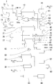
前記図1において本実施形態に係る活性炭製造システム1は、所定量の小片状の木質材料を加熱して乾燥させる乾燥装置10と、乾燥した前記木質材料を加熱して炭化する炭化部としての第1の炭化装置21及び第2の炭化装置22と、各炭化装置で炭化された炭化物を賦活して活性炭とする賦活装置30と、水を加熱して乾燥装置10の熱源となる飽和水蒸気を発生させるボイラ41と、水を加熱して第1の炭化装置21の熱源となる過熱水蒸気を発生させるボイラ42と、第2の炭化装置22に燃焼ガスを供給する燃焼器51と、賦活装置30に燃焼ガスを供給する燃焼器52と、水の電気分解により酸素と水素の混合気体を生成し、この混合気体を燃料としてボイラ41、42や燃焼器51、52にそれぞれ供給する電気分解装置61、62、63と、純水を製造し、この純水を電気分解装置63に対し電気分解される原料の水として供給する純水製造装置70と、賦活装置30で得られた活性炭を冷却する冷却装置80と、活性炭を収容し貯蔵する貯蔵タンク90とを備える構成である。
第1の炭化装置21において、木質材料を収容する炉内には、一般的な炭化の工程と同様、雰囲気として窒素等の不活性ガスが導入される。
第2の炭化装置22においても、炉内には一般的な炭化の工程と同様、雰囲気として窒素等の不活性ガスが導入される。
この第2の炭化装置からは、炭化の進行に伴い、水素や一酸化炭素等の熱分解ガスが分離するが、こうしたガスは炉外に排出され、無害化した状態で大気中に放出される。
賦活装置30において、炭化物を収容する炉内には、炭化物のガス賦活による一般的な活性炭製造工程と同様、雰囲気として二酸化炭素や水蒸気等の反応用のガスが導入される。
こうして得られた活性炭は冷却装置80で常温まで冷却された後、貯蔵タンク90に収容され、所定量溜ったら取出されて使用等のために搬出されることとなる。
本発明の第2の実施形態に係る活性炭製造システムを前記図2に基づいて説明する。
前記図2において本実施形態に係る活性炭製造システム2は、前記第1の実施形態同様、乾燥装置10と、第1の炭化装置21及び第2の炭化装置22と、賦活装置30と、ボイラ41、42と、燃焼器51、52と、電気分解装置61、62、63と、純水製造装置70と、冷却装置80と、貯蔵タンク90とを備える一方、異なる点として、乾燥装置10で使用済みの飽和水蒸気や第1の炭化装置21で使用済みの過熱水蒸気のそれぞれ保有する熱を利用して発電し電力を得る熱回収発電装置60を備える構成を有するものである。
一方、木質材料を加熱した後、乾燥装置10から排出される飽和水蒸気由来の水分は、熱回収発電装置60の蒸発器64に導入される。
こうして得られた活性炭は、前記第1の実施形態同様、冷却装置80で室温まで冷却された後、貯蔵タンク90に一時収容され、最終的に使用等のために搬出されることとなる。
10 乾燥装置
11、24 水タンク
12、25 ポンプ
21 第1の炭化装置
22 第2の炭化装置
23、26 凝縮器
27 タンク
51、52 燃焼器
30 賦活装置
41、42 ボイラ
43 過熱器
51、52 燃焼器
60 熱回収発電装置
61、62、63 電気分解装置
64 蒸発器
64a 副蒸発器
65 過熱器
66 タービン
67 発電機
68 凝縮器
69 ポンプ
70 純水製造装置
71 加熱部
72 蒸発凝縮部
73 水タンク
74 水供給タンク
80 冷却装置
90 貯蔵タンク
Claims (7)
- 小片状の木質材料を加熱して乾燥させる乾燥装置と、
乾燥した前記木質材料を加熱して炭化する炭化部と、
前記木質材料の炭化した炭化物を賦活して活性炭とする賦活装置とを少なくとも備え、
前記乾燥装置は、熱源として約100ないし120℃の飽和水蒸気を用い、炉内に収容した加熱対象物を炉外から加熱する外熱式の装置であり、
前記炭化部は、熱源として約150ないし400℃の過熱水蒸気を用い、炉内に収容した加熱対象物を炉外から加熱する外熱式の装置である一又は複数の第1の炭化装置と、約400ないし800℃の熱源で炉内に収容した加熱対象物を炉外から加熱する装置であり、前記第1の炭化装置の後段側に配設される一又は複数の第2の炭化装置とを有してなり、
前記賦活装置は、約800ないし950℃の熱源で炉内に収容した炭化物を炉外から加熱する装置であり、
前記乾燥装置で用いられた後の飽和水蒸気、及び、前記第1の炭化装置で用いられた後の過熱水蒸気は、凝縮して水となった後に再度加熱されて前記飽和水蒸気及び過熱水蒸気として循環使用されることを
特徴とする活性炭製造システム。 - 前記請求項1に記載の活性炭製造システムにおいて、
前記炭化部の第2の炭化装置で用いられる熱源、及び/又は、賦活装置で用いられる熱源が、水を電気分解して得られた水素と酸素の混合気体の燃焼により得られた燃焼ガスであることを
特徴とする活性炭製造システム。 - 前記請求項1に記載の活性炭製造システムにおいて、
前記炭化部の第2の炭化装置で用いられる熱源、及び/又は、賦活装置で用いられる熱源が、可燃性を有する有機物からなる燃料の燃焼により得られた燃焼ガスに、水を電気分解して得られた水素と酸素の混合気体を混入させたガスであることを
特徴とする活性炭製造システム。 - 前記請求項2に記載の活性炭製造システムにおいて、
原料となる水を蒸発、凝縮させる過程で不純物を除去して純水を得る純水製造装置を備え、
前記混合気体を得るために電気分解される水として、前記純水製造装置で製造された純水を供給し、
前記純水製造装置では、前記乾燥装置で前記木質材料の乾燥により分離され取出された水分を、前記原料となる水と熱交換させ、水を蒸発に適した温度に加熱することを
特徴とする活性炭製造システム。 - 前記請求項2又は4に記載の活性炭製造システムにおいて、
前記乾燥装置で用いられる飽和水蒸気を生じさせる加熱源、及び/又は前記炭化部の第1の炭化装置で用いられる過熱水蒸気を生じさせる加熱源として、水を電気分解して得られた水素と酸素の混合気体の燃焼により得られた熱を用いることを
特徴とする活性炭製造システム。 - 前記請求項1ないし5のいずれかに記載の活性炭製造システムにおいて、
前記乾燥装置で飽和水蒸気として用いられた後、乾燥装置を出た飽和水蒸気由来の水分、及び/又は、前記第1の炭化装置で過熱水蒸気として用いられた後、第1の炭化装置を出た過熱水蒸気由来の水分、の保有する熱で所定の作動流体を加熱して作動流体の蒸気動力サイクルを稼働させ、当該サイクルにより得られる動力で発電する熱回収発電装置を備えることを
特徴とする活性炭製造システム。 - 前記請求項6に記載の活性炭製造システムにおいて、
前記乾燥装置で前記木質材料の乾燥により分離され取出された水分についても、前記作動流体と熱交換させて作動流体を加熱することを
特徴とする活性炭製造システム。
Priority Applications (8)
| Application Number | Priority Date | Filing Date | Title |
|---|---|---|---|
| JP2012524027A JP5099939B1 (ja) | 2012-05-02 | 2012-05-02 | 活性炭製造システム |
| KR1020137035162A KR20150005855A (ko) | 2012-05-02 | 2012-05-02 | 활성탄 제조 시스템 |
| CN201280060841.0A CN103974903B (zh) | 2012-05-02 | 2012-05-02 | 活性炭制造系统 |
| EP12875829.9A EP2851343A4 (en) | 2012-05-02 | 2012-05-02 | CHARCOAL PRODUCTION SYSTEM |
| PCT/JP2012/061615 WO2013164894A1 (ja) | 2012-05-02 | 2012-05-02 | 活性炭製造システム |
| BR112014026843A BR112014026843A2 (pt) | 2012-05-02 | 2012-05-02 | sistema para produção de carvão ativado |
| PH12014502279A PH12014502279B1 (en) | 2012-05-02 | 2014-10-09 | Activated carbon manufacturing system |
| US14/529,724 US9242866B2 (en) | 2012-05-02 | 2014-10-31 | Activated carbon manufacturing system |
Applications Claiming Priority (1)
| Application Number | Priority Date | Filing Date | Title |
|---|---|---|---|
| PCT/JP2012/061615 WO2013164894A1 (ja) | 2012-05-02 | 2012-05-02 | 活性炭製造システム |
Related Child Applications (1)
| Application Number | Title | Priority Date | Filing Date |
|---|---|---|---|
| US14/529,724 Continuation US9242866B2 (en) | 2012-05-02 | 2014-10-31 | Activated carbon manufacturing system |
Publications (1)
| Publication Number | Publication Date |
|---|---|
| WO2013164894A1 true WO2013164894A1 (ja) | 2013-11-07 |
Family
ID=47528465
Family Applications (1)
| Application Number | Title | Priority Date | Filing Date |
|---|---|---|---|
| PCT/JP2012/061615 Ceased WO2013164894A1 (ja) | 2012-05-02 | 2012-05-02 | 活性炭製造システム |
Country Status (8)
| Country | Link |
|---|---|
| US (1) | US9242866B2 (ja) |
| EP (1) | EP2851343A4 (ja) |
| JP (1) | JP5099939B1 (ja) |
| KR (1) | KR20150005855A (ja) |
| CN (1) | CN103974903B (ja) |
| BR (1) | BR112014026843A2 (ja) |
| PH (1) | PH12014502279B1 (ja) |
| WO (1) | WO2013164894A1 (ja) |
Families Citing this family (7)
| Publication number | Priority date | Publication date | Assignee | Title |
|---|---|---|---|---|
| JP6613822B2 (ja) * | 2015-11-04 | 2019-12-04 | Jfeエンジニアリング株式会社 | 廃棄物焼却及び水素製造装置並びに方法 |
| CN105759867B (zh) * | 2016-04-15 | 2017-10-20 | 江苏优华达环保材料科技有限公司 | 活性炭生产制备自动温控系统及温控方法 |
| TWI625386B (zh) * | 2017-03-22 | 2018-06-01 | Wang Er Rui | Vinegar and activated carbon continuous operation generating device |
| CN108745331B (zh) * | 2018-07-12 | 2024-02-13 | 中冶长天国际工程有限责任公司 | 一种新型活性炭解析塔以及活性炭解析工艺 |
| CN113735119B (zh) * | 2021-09-28 | 2023-09-01 | 南平元力活性炭有限公司 | 一种利用稻壳联产中孔发达活性炭和高模数硅酸盐的方法 |
| CN115974080B (zh) * | 2023-01-18 | 2024-05-03 | 华中农业大学 | 一种水蒸气循环区段分级热解制备生物炭的方法及装置 |
| KR102610219B1 (ko) * | 2023-09-01 | 2023-12-06 | (주)이수카본 | 수율 개선을 위한 활성탄 제조방법 |
Citations (4)
| Publication number | Priority date | Publication date | Assignee | Title |
|---|---|---|---|---|
| JP2004161574A (ja) | 2002-11-15 | 2004-06-10 | Tsukishima Kikai Co Ltd | 木質系バイオマスから活性炭を得る方法及び設備 |
| WO2005063923A1 (ja) * | 2003-12-08 | 2005-07-14 | Intellectual Property Bank Corp. | 活性炭製造用炭化装置 |
| JP2007186403A (ja) * | 2005-10-27 | 2007-07-26 | Showa Denko Kk | 活性炭、その製造方法及び用途 |
| WO2011059095A1 (ja) * | 2009-11-16 | 2011-05-19 | 株式会社上原Otec研究所 | プラスチック処理装置 |
Family Cites Families (11)
| Publication number | Priority date | Publication date | Assignee | Title |
|---|---|---|---|---|
| AT407871B (de) * | 1995-11-13 | 2001-07-25 | Burgenlaendische Elek Zitaetsw | Verfahren zur herstellung von aktivkohle aus pflanzlichem material |
| JP2001220121A (ja) * | 2000-02-10 | 2001-08-14 | Nkk Design & Engineering Corp | 廃棄物からの活性炭製造方法及び製造装置 |
| US7964530B2 (en) | 2005-09-29 | 2011-06-21 | Showa Denko K.K. | Activated carbon and process of making the same |
| JP4963616B2 (ja) * | 2006-03-23 | 2012-06-27 | Jx日鉱日石エネルギー株式会社 | 炭化水素油中の微量成分を除去する吸着剤及びその製造方法 |
| US8088832B2 (en) * | 2006-04-05 | 2012-01-03 | Woodland Biofuels Inc. | System and method for converting biomass to ethanol via syngas |
| JP2009179485A (ja) * | 2006-04-10 | 2009-08-13 | Ipb:Kk | 活性炭及びその製造方法、並びに製造装置 |
| JP5183943B2 (ja) * | 2007-03-12 | 2013-04-17 | 地方独立行政法人 大阪市立工業研究所 | 金属含有炭化物およびその製造方法 |
| US20100113267A1 (en) * | 2007-05-17 | 2010-05-06 | Srivats Srinivasachar | System and method for coproduction of activated carbon and steam/electricity |
| CN201172626Y (zh) * | 2008-01-15 | 2008-12-31 | 章水根 | 内外热结合的二级连续式活性炭生产装置 |
| US9121606B2 (en) * | 2008-02-19 | 2015-09-01 | Srivats Srinivasachar | Method of manufacturing carbon-rich product and co-products |
| CN102311742B (zh) * | 2011-08-18 | 2014-07-02 | 中国科学院过程工程研究所 | 一种纤维素工业生物质废弃物的加工方法及其工艺装置 |
-
2012
- 2012-05-02 WO PCT/JP2012/061615 patent/WO2013164894A1/ja not_active Ceased
- 2012-05-02 KR KR1020137035162A patent/KR20150005855A/ko not_active Ceased
- 2012-05-02 BR BR112014026843A patent/BR112014026843A2/pt not_active IP Right Cessation
- 2012-05-02 EP EP12875829.9A patent/EP2851343A4/en not_active Withdrawn
- 2012-05-02 JP JP2012524027A patent/JP5099939B1/ja not_active Expired - Fee Related
- 2012-05-02 CN CN201280060841.0A patent/CN103974903B/zh not_active Expired - Fee Related
-
2014
- 2014-10-09 PH PH12014502279A patent/PH12014502279B1/en unknown
- 2014-10-31 US US14/529,724 patent/US9242866B2/en not_active Expired - Fee Related
Patent Citations (4)
| Publication number | Priority date | Publication date | Assignee | Title |
|---|---|---|---|---|
| JP2004161574A (ja) | 2002-11-15 | 2004-06-10 | Tsukishima Kikai Co Ltd | 木質系バイオマスから活性炭を得る方法及び設備 |
| WO2005063923A1 (ja) * | 2003-12-08 | 2005-07-14 | Intellectual Property Bank Corp. | 活性炭製造用炭化装置 |
| JP2007186403A (ja) * | 2005-10-27 | 2007-07-26 | Showa Denko Kk | 活性炭、その製造方法及び用途 |
| WO2011059095A1 (ja) * | 2009-11-16 | 2011-05-19 | 株式会社上原Otec研究所 | プラスチック処理装置 |
Non-Patent Citations (1)
| Title |
|---|
| See also references of EP2851343A4 |
Also Published As
| Publication number | Publication date |
|---|---|
| US20150050192A1 (en) | 2015-02-19 |
| CN103974903B (zh) | 2016-05-25 |
| US9242866B2 (en) | 2016-01-26 |
| PH12014502279A1 (en) | 2014-12-15 |
| JPWO2013164894A1 (ja) | 2015-12-24 |
| PH12014502279B1 (en) | 2014-12-15 |
| CN103974903A (zh) | 2014-08-06 |
| EP2851343A1 (en) | 2015-03-25 |
| EP2851343A4 (en) | 2016-03-09 |
| JP5099939B1 (ja) | 2012-12-19 |
| KR20150005855A (ko) | 2015-01-15 |
| BR112014026843A2 (pt) | 2017-07-18 |
Similar Documents
| Publication | Publication Date | Title |
|---|---|---|
| JP5099939B1 (ja) | 活性炭製造システム | |
| Abd El-Sattar et al. | Tri-generation biomass system based on externally fired gas turbine, organic rankine cycle and absorption chiller | |
| CN102016240B (zh) | 通过利用高压和适中温度的蒸汽的热循环产生能量的方法 | |
| CN1671463A (zh) | 低排放热电厂 | |
| JP2006218383A (ja) | 高含水有機廃棄物の処理システム | |
| JP2017043657A (ja) | 半炭化物製造装置及び発電システム | |
| JP2005146185A (ja) | 植物系バイオマス資源利用設備 | |
| US20140230437A1 (en) | Method for generating heat energy and electrical energy from various types of waste and system for implementing said method | |
| CN107792329A (zh) | 动力与水联合供应方法 | |
| JP6026075B2 (ja) | 有機汚泥の燃料化装置 | |
| KR20090101347A (ko) | 혼합 증기를 생성하기 위한 방법 | |
| KR100810025B1 (ko) | 음식물 쓰레기 탄화처리장치 | |
| RU2552481C1 (ru) | Способ работы тепловой электрической станции | |
| RU2548962C2 (ru) | Способ деаэрации воды для тепловой электрической станции | |
| RU2784165C1 (ru) | Способ работы парогазовой установки электростанции | |
| CN209989236U (zh) | 一种污泥干化处理系统 | |
| RU2793046C1 (ru) | Парогазовая установка электростанции | |
| RU2738792C1 (ru) | Парогазовая установка электростанции | |
| RU2482292C2 (ru) | Парогазовая установка электростанции | |
| LT5861B (lt) | Integruota sistema, susidedanti iš šilumos jėgainės, elektrinės bei pirolizės būdu gaminamų produktų linijios modulių, šios sistemos modulių patobulinimas ir jos panaudojimo būdas | |
| JP2004143253A (ja) | 植物性有機廃棄物炭化システム | |
| RU2620610C1 (ru) | Способ работы парогазовой установки электростанции | |
| RU2780597C1 (ru) | Способ работы парогазовой установки электростанции | |
| CN105782994B (zh) | 一种用于工业危险废物处置行业的余热发电系统 | |
| RU2272915C1 (ru) | Способ работы газопаровой установки |
Legal Events
| Date | Code | Title | Description |
|---|---|---|---|
| ENP | Entry into the national phase |
Ref document number: 2012524027 Country of ref document: JP Kind code of ref document: A |
|
| 121 | Ep: the epo has been informed by wipo that ep was designated in this application |
Ref document number: 12875829 Country of ref document: EP Kind code of ref document: A1 |
|
| ENP | Entry into the national phase |
Ref document number: 20137035162 Country of ref document: KR Kind code of ref document: A |
|
| WWE | Wipo information: entry into national phase |
Ref document number: 2012875829 Country of ref document: EP |
|
| NENP | Non-entry into the national phase |
Ref country code: DE |
|
| REG | Reference to national code |
Ref country code: BR Ref legal event code: B01A Ref document number: 112014026843 Country of ref document: BR |
|
| ENP | Entry into the national phase |
Ref document number: 112014026843 Country of ref document: BR Kind code of ref document: A2 Effective date: 20141027 |