WO2013164936A1 - 空調システム及び除霜運転方法 - Google Patents
空調システム及び除霜運転方法 Download PDFInfo
- Publication number
- WO2013164936A1 WO2013164936A1 PCT/JP2013/060151 JP2013060151W WO2013164936A1 WO 2013164936 A1 WO2013164936 A1 WO 2013164936A1 JP 2013060151 W JP2013060151 W JP 2013060151W WO 2013164936 A1 WO2013164936 A1 WO 2013164936A1
- Authority
- WO
- WIPO (PCT)
- Prior art keywords
- defrosting operation
- indoor units
- temperature
- indoor
- unit
- Prior art date
- Legal status (The legal status is an assumption and is not a legal conclusion. Google has not performed a legal analysis and makes no representation as to the accuracy of the status listed.)
- Ceased
Links
Images



Classifications
-
- F—MECHANICAL ENGINEERING; LIGHTING; HEATING; WEAPONS; BLASTING
- F24—HEATING; RANGES; VENTILATING
- F24F—AIR-CONDITIONING; AIR-HUMIDIFICATION; VENTILATION; USE OF AIR CURRENTS FOR SCREENING
- F24F11/00—Control or safety arrangements
- F24F11/30—Control or safety arrangements for purposes related to the operation of the system, e.g. for safety or monitoring
-
- F—MECHANICAL ENGINEERING; LIGHTING; HEATING; WEAPONS; BLASTING
- F25—REFRIGERATION OR COOLING; COMBINED HEATING AND REFRIGERATION SYSTEMS; HEAT PUMP SYSTEMS; MANUFACTURE OR STORAGE OF ICE; LIQUEFACTION SOLIDIFICATION OF GASES
- F25D—REFRIGERATORS; COLD ROOMS; ICE-BOXES; COOLING OR FREEZING APPARATUS NOT OTHERWISE PROVIDED FOR
- F25D21/00—Defrosting; Preventing frosting; Removing condensed or defrost water
- F25D21/002—Defroster control
- F25D21/004—Control mechanisms
-
- F—MECHANICAL ENGINEERING; LIGHTING; HEATING; WEAPONS; BLASTING
- F24—HEATING; RANGES; VENTILATING
- F24F—AIR-CONDITIONING; AIR-HUMIDIFICATION; VENTILATION; USE OF AIR CURRENTS FOR SCREENING
- F24F11/00—Control or safety arrangements
- F24F11/89—Arrangement or mounting of control or safety devices
-
- F—MECHANICAL ENGINEERING; LIGHTING; HEATING; WEAPONS; BLASTING
- F24—HEATING; RANGES; VENTILATING
- F24F—AIR-CONDITIONING; AIR-HUMIDIFICATION; VENTILATION; USE OF AIR CURRENTS FOR SCREENING
- F24F11/00—Control or safety arrangements
- F24F11/30—Control or safety arrangements for purposes related to the operation of the system, e.g. for safety or monitoring
- F24F11/41—Defrosting; Preventing freezing
- F24F11/42—Defrosting; Preventing freezing of outdoor units
-
- F—MECHANICAL ENGINEERING; LIGHTING; HEATING; WEAPONS; BLASTING
- F24—HEATING; RANGES; VENTILATING
- F24F—AIR-CONDITIONING; AIR-HUMIDIFICATION; VENTILATION; USE OF AIR CURRENTS FOR SCREENING
- F24F11/00—Control or safety arrangements
- F24F11/70—Control systems characterised by their outputs; Constructional details thereof
- F24F11/72—Control systems characterised by their outputs; Constructional details thereof for controlling the supply of treated air, e.g. its pressure
- F24F11/74—Control systems characterised by their outputs; Constructional details thereof for controlling the supply of treated air, e.g. its pressure for controlling air flow rate or air velocity
- F24F11/77—Control systems characterised by their outputs; Constructional details thereof for controlling the supply of treated air, e.g. its pressure for controlling air flow rate or air velocity by controlling the speed of ventilators
-
- F—MECHANICAL ENGINEERING; LIGHTING; HEATING; WEAPONS; BLASTING
- F25—REFRIGERATION OR COOLING; COMBINED HEATING AND REFRIGERATION SYSTEMS; HEAT PUMP SYSTEMS; MANUFACTURE OR STORAGE OF ICE; LIQUEFACTION SOLIDIFICATION OF GASES
- F25B—REFRIGERATION MACHINES, PLANTS OR SYSTEMS; COMBINED HEATING AND REFRIGERATION SYSTEMS; HEAT PUMP SYSTEMS
- F25B13/00—Compression machines, plants or systems, with reversible cycle
-
- F—MECHANICAL ENGINEERING; LIGHTING; HEATING; WEAPONS; BLASTING
- F25—REFRIGERATION OR COOLING; COMBINED HEATING AND REFRIGERATION SYSTEMS; HEAT PUMP SYSTEMS; MANUFACTURE OR STORAGE OF ICE; LIQUEFACTION SOLIDIFICATION OF GASES
- F25B—REFRIGERATION MACHINES, PLANTS OR SYSTEMS; COMBINED HEATING AND REFRIGERATION SYSTEMS; HEAT PUMP SYSTEMS
- F25B47/00—Arrangements for preventing or removing deposits or corrosion, not provided for in another subclass
- F25B47/02—Defrosting cycles
- F25B47/022—Defrosting cycles hot gas defrosting
- F25B47/025—Defrosting cycles hot gas defrosting by reversing the cycle
-
- F—MECHANICAL ENGINEERING; LIGHTING; HEATING; WEAPONS; BLASTING
- F24—HEATING; RANGES; VENTILATING
- F24F—AIR-CONDITIONING; AIR-HUMIDIFICATION; VENTILATION; USE OF AIR CURRENTS FOR SCREENING
- F24F2110/00—Control inputs relating to air properties
- F24F2110/10—Temperature
- F24F2110/12—Temperature of the outside air
-
- F—MECHANICAL ENGINEERING; LIGHTING; HEATING; WEAPONS; BLASTING
- F24—HEATING; RANGES; VENTILATING
- F24F—AIR-CONDITIONING; AIR-HUMIDIFICATION; VENTILATION; USE OF AIR CURRENTS FOR SCREENING
- F24F2120/00—Control inputs relating to users or occupants
- F24F2120/10—Occupancy
-
- F—MECHANICAL ENGINEERING; LIGHTING; HEATING; WEAPONS; BLASTING
- F24—HEATING; RANGES; VENTILATING
- F24F—AIR-CONDITIONING; AIR-HUMIDIFICATION; VENTILATION; USE OF AIR CURRENTS FOR SCREENING
- F24F2140/00—Control inputs relating to system states
- F24F2140/20—Heat-exchange fluid temperature
-
- F—MECHANICAL ENGINEERING; LIGHTING; HEATING; WEAPONS; BLASTING
- F25—REFRIGERATION OR COOLING; COMBINED HEATING AND REFRIGERATION SYSTEMS; HEAT PUMP SYSTEMS; MANUFACTURE OR STORAGE OF ICE; LIQUEFACTION SOLIDIFICATION OF GASES
- F25B—REFRIGERATION MACHINES, PLANTS OR SYSTEMS; COMBINED HEATING AND REFRIGERATION SYSTEMS; HEAT PUMP SYSTEMS
- F25B2313/00—Compression machines, plants or systems with reversible cycle not otherwise provided for
- F25B2313/023—Compression machines, plants or systems with reversible cycle not otherwise provided for using multiple indoor units
- F25B2313/0233—Compression machines, plants or systems with reversible cycle not otherwise provided for using multiple indoor units in parallel arrangements
-
- F—MECHANICAL ENGINEERING; LIGHTING; HEATING; WEAPONS; BLASTING
- F25—REFRIGERATION OR COOLING; COMBINED HEATING AND REFRIGERATION SYSTEMS; HEAT PUMP SYSTEMS; MANUFACTURE OR STORAGE OF ICE; LIQUEFACTION SOLIDIFICATION OF GASES
- F25B—REFRIGERATION MACHINES, PLANTS OR SYSTEMS; COMBINED HEATING AND REFRIGERATION SYSTEMS; HEAT PUMP SYSTEMS
- F25B2313/00—Compression machines, plants or systems with reversible cycle not otherwise provided for
- F25B2313/029—Control issues
- F25B2313/0293—Control issues related to the indoor fan, e.g. controlling speed
-
- F—MECHANICAL ENGINEERING; LIGHTING; HEATING; WEAPONS; BLASTING
- F25—REFRIGERATION OR COOLING; COMBINED HEATING AND REFRIGERATION SYSTEMS; HEAT PUMP SYSTEMS; MANUFACTURE OR STORAGE OF ICE; LIQUEFACTION SOLIDIFICATION OF GASES
- F25B—REFRIGERATION MACHINES, PLANTS OR SYSTEMS; COMBINED HEATING AND REFRIGERATION SYSTEMS; HEAT PUMP SYSTEMS
- F25B2313/00—Compression machines, plants or systems with reversible cycle not otherwise provided for
- F25B2313/031—Sensor arrangements
- F25B2313/0315—Temperature sensors near the outdoor heat exchanger
-
- F—MECHANICAL ENGINEERING; LIGHTING; HEATING; WEAPONS; BLASTING
- F25—REFRIGERATION OR COOLING; COMBINED HEATING AND REFRIGERATION SYSTEMS; HEAT PUMP SYSTEMS; MANUFACTURE OR STORAGE OF ICE; LIQUEFACTION SOLIDIFICATION OF GASES
- F25B—REFRIGERATION MACHINES, PLANTS OR SYSTEMS; COMBINED HEATING AND REFRIGERATION SYSTEMS; HEAT PUMP SYSTEMS
- F25B2700/00—Sensing or detecting of parameters; Sensors therefor
- F25B2700/21—Temperatures
- F25B2700/2106—Temperatures of fresh outdoor air
-
- Y—GENERAL TAGGING OF NEW TECHNOLOGICAL DEVELOPMENTS; GENERAL TAGGING OF CROSS-SECTIONAL TECHNOLOGIES SPANNING OVER SEVERAL SECTIONS OF THE IPC; TECHNICAL SUBJECTS COVERED BY FORMER USPC CROSS-REFERENCE ART COLLECTIONS [XRACs] AND DIGESTS
- Y02—TECHNOLOGIES OR APPLICATIONS FOR MITIGATION OR ADAPTATION AGAINST CLIMATE CHANGE
- Y02B—CLIMATE CHANGE MITIGATION TECHNOLOGIES RELATED TO BUILDINGS, e.g. HOUSING, HOUSE APPLIANCES OR RELATED END-USER APPLICATIONS
- Y02B30/00—Energy efficient heating, ventilation or air conditioning [HVAC]
- Y02B30/70—Efficient control or regulation technologies, e.g. for control of refrigerant flow, motor or heating
Definitions
- the present invention relates to an air conditioning system using an air conditioner, and more particularly, to a defrosting operation for removing frost formation on a heat exchanger of an outdoor unit.
- the heat exchanger of the outdoor unit When performing heating operation with an air conditioner, in a cold region, the heat exchanger of the outdoor unit may be frosted and the amount of frost formation may increase. Since frost formation prevents heat exchange, it is necessary to perform a defrosting operation (see, for example, Patent Document 1).
- an object of the present invention is to provide an air conditioning system and a defrosting operation method that can shorten the time required for defrosting.
- the air conditioning system of the present invention includes a plurality of indoor units, an outdoor unit sharing a refrigerant system with the plurality of indoor units, a first temperature sensor for detecting an outside air temperature, and a heat exchanger for the outdoor unit. Defrosting in a state in which the second temperature sensor for detecting the temperature of the indoor unit, the human detection sensor for detecting whether or not there is a person in each of the air blowable areas of the indoor unit, and the fans of all the indoor units are stopped When it is estimated that the amount of frost on the heat exchanger exceeds the threshold based on the first defrosting operation mode in which the operation is performed and the temperatures detected by the first and second temperature sensors, respectively.
- the second defrosting operation mode in which the indoor unit in which the human detection sensor does not detect a person is preferentially selected in the blowable area and the defrosting operation is performed while forcibly operating the fan of the indoor unit is selectively performed. And an executable control unit.
- the defrosting operation when it is estimated that the amount of frost on the heat exchanger exceeds the threshold value, the defrosting operation is performed while forcibly operating the fan of at least one indoor unit.
- the fan By operating the fan, heat exchange between the indoor air and the refrigerant is promoted, and defrosting is performed more quickly. Further, when the fan is operated, cold air is blown into the room, but when there is no person in the blowable area, there is no fear of giving unpleasant feeling (feeling cold).
- the control unit performs forced operation based on the temperature detected by the second temperature sensor after a predetermined time has elapsed since the execution of the second defrosting operation mode was started. It may be determined whether or not it is necessary to increase the power, and at least one of the number of rotations of the fan and the number of indoor units that operate the fan may be increased only when the power is required to be increased. For example, when the temperature of the heat exchanger does not become higher than a predetermined value even after a lapse of a certain time from the start of the execution of the second defrosting operation mode, that is, when the progress of defrosting is slow due to a large amount of frost formation.
- a setting switch that can use the second defrosting operation mode may be provided in the outdoor unit.
- the second defrosting operation mode can be easily used by operating the setting switch.
- it can cancel
- the indoor unit, the outdoor unit, and the first and second temperature sensors include at least two systems of the first system and the second system, and one room
- the controller when executing the second defrosting operation mode in the first system, uses the second system as a heating operation and turns on the fan of the indoor unit in the room. You may make it drive. In this case, when there is a person in the room, even if the cool air is blown from the first system indoor unit, the warm air can be blown from the second system indoor unit. It is possible to neutralize (or alleviate) the unpleasant sensation caused by the balloons.
- the present invention is a defrosting operation method in an air conditioning system including a plurality of indoor units and an outdoor unit sharing a refrigerant system with the plurality of indoor units, wherein (a) the outside air temperature and the outdoor The temperature of the heat exchanger of each unit is detected by a temperature sensor, (b) whether or not there is a person in each air blowable area of the indoor unit is detected by a human detection sensor, and (c) all the indoor units are Based on the first defrosting operation mode in which the defrosting operation is performed with the fan stopped, and the temperatures detected by the first and second temperature sensors, the amount of frost formation on the heat exchanger is a threshold value.
- the indoor unit in which the human detection sensor does not detect a person is preferentially selected in the blowable area, and the defrosting operation is performed while forcibly operating the fan of the indoor unit.
- the defrosting operation mode is controlled by the control unit. Run into ⁇ , characterized in that.
- the defrosting operation when it is estimated that the amount of frost on the heat exchanger exceeds the threshold value, the defrosting operation is performed while forcibly operating the fan of at least one indoor unit.
- the fan By operating the fan, heat exchange between the indoor air and the refrigerant is promoted, and defrosting is performed more quickly. Further, when the fan is operated, cold air is blown into the room, but when there is no person in the blowable area, there is no fear of giving unpleasant feeling (feeling cold).
- the time required for defrosting can be shortened.
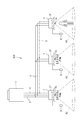
- FIG. 1 It is a lineblock diagram of the air-conditioning system concerning a 1st embodiment of the present invention. It is a figure which shows schematic structure of an outdoor unit. It is a flowchart which shows the procedure of the defrost operation method of this embodiment performed by the control part of an outdoor unit.
- FIG. 1 it is a diagram illustrating a state in which a fan of one indoor unit is operated when a person is in the area of a certain indoor unit.
- FIG. 1 when a person is in the area of a certain indoor unit, it is a diagram illustrating how the fans of the two indoor units are operated.
- FIG. 1 when a person is in the area of a certain indoor unit, it is a diagram illustrating how the fans of the two indoor units are operated.
- It is a block diagram of the air conditioning system which concerns on 2nd Embodiment of this invention.
- FIG. 1 is a configuration diagram of an air conditioning system according to the first embodiment of the present invention.
- this air conditioning system 100 one outdoor unit 1 and a plurality of (three) indoor units 2, 3, and 4 are connected via a refrigerant pipe 5, and share a refrigerant system.
- the outdoor unit 1 and the indoor units 2, 3, 4 are connected to each other by the communication line 6.
- Remote control operators 2r, 3r, 4r for operation are connected to the indoor units 2, 3, 4 respectively.
- the indoor units 2, 3, and 4 incorporate fans 2f, 3f, and 4f, respectively.
- the number of indoor units is just an example.
- the outdoor unit 1 is set to one, if necessary, a plurality of outdoor units may be provided. Also, illustration of the power line is omitted.
- the indoor units 2, 3 and 4 are provided with human detection sensors 2s, 3s and 4s, respectively.
- the human detection sensors 2s, 3s, and 4s are, for example, pyroelectric infrared sensors that detect infrared rays emitted by people in the blowable areas A2, A3, and A4 of the indoor units 2, 3, and 4, and determine whether or not a person exists. Can be caught. Note that the figure shows a simplified circular (conical) region. Actually, by providing a plurality of human detection sensors for each indoor unit in accordance with the expansion of the air blowable area of the indoor unit, the detection target area is shifted for each sensor so that a wide range can be obtained with all sensors. You may comprise so that it can detect.
- the human detection sensors 2s, 3s, and 4s are not necessarily provided in the casings as accessories of the indoor units 2, 3, and 4.
- the human detection sensors 2s, 3s, and 4s are arranged on the ceiling of the room and output thereof. You may make it send to the indoor units 2, 3, 4 or the outdoor unit 1.
- the indoor units 2, 3, and 4 are partitioned as rooms, it is possible to detect whether or not there is a person in the room, not limited to the blowable area.
- FIG. 2 is a diagram showing a schematic configuration of the outdoor unit 1.
- the outdoor unit 1 includes a compressor 12, a four-way switching valve 13, an accumulator 14, a heat exchanger 15, an expansion valve 16, a fan 17, temperature sensors 18 and 19, and a control unit 20 in a housing 11.
- the temperature sensor 19 is a thermistor, for example, and is attached in contact with the refrigerant pipe P ⁇ b> 1 at the end of the heat exchanger 15.
- the temperature sensor 19 detects the temperature Tb at the end of the heat exchanger 15 on the low temperature side (hereinafter simply referred to as the temperature of the heat exchanger 15).
- the temperature sensor 18 is a thermistor, for example, and detects the outside air temperature sucked by the operation of the fan 17.
- the temperature sensors 18 and 19 are connected to the control unit 20 via cables 18a and 19a, respectively.
- the control unit 20 is equipped with a CPU and other central control functions, whereby the actuators (compressor 12, four-way switching valve 13, expansion valve 16, fan 17, etc.) of the outdoor unit 1 and the indoor units 2 to 4 are controlled. Control is performed. Further, the control unit 20 is provided with a setting switch 20s. By operating the setting switch 20s, for example, a case where only the first defrosting operation mode, which will be described later, is used, and a case where the first and second defrosting operation modes are selectively used are requested by the user, for example. You can use them according to your needs.
- the four-way switching valve 13 is in the state shown in the solid line, and the high-pressure gas refrigerant discharged from the compressor 12 is condensed by exchanging heat with the outside air in the heat exchanger 15. Becomes a refrigerant.
- the liquid refrigerant is decompressed by the expansion valve 16 and then sent to the indoor units 2 to 4 (FIG. 1).
- the gas refrigerant after evaporating by exchanging heat with room air in the indoor units 2 to 4 returns to the outdoor unit 1 and is sent to the compressor 12 through the four-way switching valve 13 and the accumulator 14. By repeating such a cycle, the cooling operation is performed.
- the four-way selector valve 13 is in the state of the dotted line shown in the figure, and the high-pressure gas refrigerant discharged from the compressor 12 is sent to the indoor units 2, 3, 4 (FIG. 1), and the indoor air and heat It is exchanged and condensed to become a liquid refrigerant.
- the liquid refrigerant returns to the outdoor unit 1, is decompressed by the expansion valve 16, and then evaporates by exchanging heat with the outside air by the heat exchanger 15.
- the evaporated gas refrigerant passes through the four-way switching valve 13 and the accumulator 14 and is sent to the compressor 12.
- the heating operation is performed by repeating such a cycle.
- the heat exchanger 15 of the outdoor unit 1 may be frosted. If the frost is allowed to grow as it is, the heating efficiency decreases, so the heating operation is temporarily stopped and the defrosting operation is performed. The refrigerant flow during the defrosting operation is the same as that during the cooling operation. At this time, conventionally, the fans of the indoor units 2 to 4 are stopped so that the cool air is not discharged into the room.
- the above defrosting operation can be performed based on, for example, the temperature Tb of the heat exchanger 15 in the outdoor unit 1.
- the temperature Tb of the heat exchanger 15 In normal heating operation, if there is no frost formation, the temperature Tb of the heat exchanger 15 is maintained at a substantially constant value To. However, if frost formation on the heat exchanger 15 gradually increases due to the continuation of the heating operation, the temperature Tb of the heat exchanger 15 gradually decreases. Therefore, when the temperature Tb detected by the temperature sensor 19 exceeds the temperature decrease width ⁇ T from To, that is, when Tb ⁇ (To ⁇ T), the amount of frost on the heat exchanger 15 is reached. Is determined to have exceeded the reference frost amount. This reference frost amount is the “before” frost amount that reduces the efficiency of the heat exchanger 15 and impedes the heating operation unless defrosting is performed.
- the end of the defrosting operation can be ended if, for example, the temperature Tb of the heat exchanger 15 rises to To.
- the frosted state It is also possible to perform the defrosting operation automatically by estimating that it is in the range. Further, it may be estimated that defrosting has been performed after a defrosting operation for a certain period of time, and the defrosting operation may be automatically terminated.
- FIG. 3 is a flowchart showing the procedure of the defrosting operation method of the present embodiment performed by the control unit 20 of the outdoor unit 1.
- indication of the start / end of defrost operation itself is performed in the above-mentioned way, it is simplified in this flowchart. That is, this flowchart mainly shows the defrosting operation that selectively uses the two modes.
- the control unit 20 stops the fans of all the indoor units 2 to 4 (step S1). This is a normal defrosting operation and is referred to as a first defrosting operation mode.
- the control unit 20 determines whether or not the temperature Tb of the heat exchanger 15 is less than 10 degrees (step S2). Here, if temperature Tb is 10 degree
- the control unit 20 determines whether or not the temperature Ta of the outside air detected by the temperature sensor 19 is less than 0 ° C. (step S3).
- the control unit 20 continues the first defrosting operation mode until the defrosting operation ends (repeat of steps S1, S2, S3, and S8). If there is a command to end the defrosting operation in step S8, the defrosting operation ends.
- step S3 when the outside air temperature Ta is less than 0 ° C., that is, when two conditions of Tb ⁇ 10 ° C. and Ta ⁇ 0 ° C. are satisfied by AND logic, the control unit 20 It is estimated that the amount exceeds the threshold value, and the second defrosting operation mode is executed (step S4).
- the threshold value of this frost amount is a value larger than the above-mentioned reference frost amount.
- any one or more fans of the indoor units 2 to 4 are forcibly operated. By operating the fan, heat exchange between the indoor air and the refrigerant is promoted, and defrosting is performed more quickly. As the number of indoor units operating the fan increases, defrosting can be accelerated. Moreover, if the number of indoor units which drive a fan is the same, defrosting can be speeded up, so that there is much ventilation volume.
- FIG. 4 is a diagram similar to FIG. 1, but illustrates a case where there is a person in the area A ⁇ b> 4 of the indoor unit 4.
- the detection signal is transmitted to the control unit 20 of the outdoor unit 1.
- the control unit 20 preferentially selects and operates the fans 2f and 3f of the indoor units 2 and 3 that do not detect a person in the blowable area.
- FIG. 4 shows how the fan 2f of the indoor unit 2 is operated, for example. Although cold air is blown out into the area A2 by the operation of the fan 2f, there is no person, so there is no discomfort.
- FIG. 5 shows how the fans 2f and 3f of the indoor units 2 and 3 are operated. Although cold air is blown out to the areas A2 and A3 by the operation of the fans 2f and 3f, there is no person, so there is no discomfort.
- the control unit 20 waits for a certain period of time after the start of the forced operation of the fan while the temperature of the heat exchanger 15 becomes higher than 11 ° C. while executing the second defrosting operation mode (step (Repeat from S5, S6 to S4).
- This 11 ° C. is a temperature at which it is determined that the first defrosting operation mode is sufficient because the frosting amount is less than the threshold value by the defrosting operation in the second defrosting operation mode.
- the difference between 10 ° C. and 1 ° C. in step S2 is to avoid hunting of the operation mode operation and to ensure that the amount of frost formation is reduced when returning to the first defrosting operation mode.
- step S8 If the temperature of the heat exchanger 15 becomes higher than 11 ° C. before the fixed time elapses, the process returns to step S1 through step S8. Thereafter, the control unit 20 performs the first defrosting operation until the defrosting operation is completed. The mode is continued (repetition of steps S1, S2 and S8). If there is a command to end the defrosting operation in step S8, the defrosting operation ends.
- step S6 when a predetermined time has elapsed after starting the forced operation without the temperature of the heat exchanger 15 being higher than 11 ° C., the control unit 20 enhances the forced operation (step S7). This is to increase the number of indoor units that operate the fans, and / or to increase the amount of air blown, that is, the number of fan rotations. Thereby, defrosting can be speeded up.
- region is not the object of priority driving
- the setting switch 20 s (FIG. 2) that enables the use of the second defrosting operation mode is provided in the outdoor unit 1, the second switch can be easily set by operating the setting switch 20 s during installation or maintenance. A defrosting operation mode can be made available. Moreover, when a user does not desire the 2nd defrost operation mode, it can cancel
- finish the 2nd defrost operation mode in the said embodiment is an example, and according to a use environment, it is a little. You can make changes.
- FIG. 6 is a configuration diagram of an air conditioning system according to the second embodiment of the present invention.
- this air conditioning system 200 has two refrigerant systems. Assuming that the two systems are the X system and the Y system, the X system includes one outdoor unit 1x and a plurality (three units) of indoor units 2x, 3x, 4x connected via the refrigerant pipe 5x. Share. Further, the outdoor unit 1x and the indoor units 2x, 3x, 4x are connected to each other by the communication line 6x.
- one outdoor unit 1y and a plurality (three) of indoor units 2y, 3y, 4y are connected via a refrigerant pipe 5y and share the refrigerant system. Further, the outdoor unit 1y and the indoor units 2y, 3y, 4y are connected to each other by the communication line 6y.
- the number of indoor units in each system is only an example. Moreover, although the outdoor units 1x and 1y are each one, if necessary, a plurality of outdoor units may be provided.
- the space to be air-conditioned is a large room 30 such as one floor of a building, for example, and there is no partition wall.
- the left outdoor unit 1x is installed under the roof R and has poor sunlight. Therefore, for example, if the temperature is lower than 0 ° C., frost formation is likely even if the weather is good, and the amount of frost formation tends to increase.
- the right outdoor unit 1y is installed in a place where it is exposed to sunlight during the daytime, and it is difficult to form frost or the amount thereof is relatively small even if it forms frost.
- Other detailed configurations are the same as those in the first embodiment.
- the outdoor unit 1x is frosted and needs a defrosting operation, but the outdoor unit 1y frequently does not need a defrosting operation. obtain.
- the X system can perform a defrosting operation
- the Y system can perform a heating operation.
- the defrosting operation method can be performed in the manner shown in the flowchart of FIG. 3 as in the first embodiment.
- the point that the cool air is sent preferentially to a space where there is no person is the same, but there is a possibility that the cool air may flow by convection as long as it is one floor.
- the X system indoor units for example, 2x, 4x
- warm air can be blown out from the Y system indoor units (2y, 3y, 4y). It is possible to neutralize (or alleviate) the discomfort caused by the blowing of cold air.
- the fan of the indoor unit 3x does not operate because there are people in the blowable area.
- FIG. 6 Although the structure of FIG. 6 is two systems, it is also possible to mix three or more systems. In this case, if the second defrosting operation mode is executed as necessary only for one system and the other two systems perform the heating operation, the entire room can further alleviate the discomfort caused by the blowing of cold air. Can do.
Landscapes
- Engineering & Computer Science (AREA)
- Mechanical Engineering (AREA)
- General Engineering & Computer Science (AREA)
- Chemical & Material Sciences (AREA)
- Combustion & Propulsion (AREA)
- Physics & Mathematics (AREA)
- Thermal Sciences (AREA)
- Fluid Mechanics (AREA)
- Air Conditioning Control Device (AREA)
Description
例えば、第2除霜運転モードの実行を開始してから一定時間経過後にも、熱交換器の温度が所定値より高くならない場合、すなわち、着霜量が多いため除霜の進行具合が遅い場合は、ファンの回転数及びファンを運転する室内機の数の少なくとも一方を増大させることで、室内の空気と冷媒との熱交換がさらに促進され、着霜量が多い場合の除霜を、迅速に行うことができる。
この場合、設定スイッチの操作によって容易に、第2除霜運転モードを利用可能とすることができる。また、ユーザが第2除霜運転モードを希望しない場合には、容易に解除することもできる。
この場合、室内に人がいる場合に、第1系統の室内機からは冷風が吹き出されても、第2系統の室内機からは温風を吹き出させることができるので、部屋全体としては、冷風の吹き出しによる不快感を中和(あるいは緩和)することができる。
図1は、本発明の第1実施形態に係る空調システムの構成図である。図において、この空調システム100は、1台の室外機1と、複数(3台)の室内機2,3,4とが、冷媒配管5を介して接続され、冷媒系統を共有している。また、通信線6によって、室外機1と、室内機2,3,4とが、相互に接続されている。室内機2,3,4には、それぞれ、操作用のリモコン操作器2r,3r,4rが接続されている。室内機2,3,4は、それぞれ、ファン2f,3f,4fを内蔵している。
なお、室内機の台数は一例に過ぎない。また、室外機1は1台としているが、必要により、室外機が複数設けられる場合もある。また、電力線の図示は省略している。
実際にはさらに、室内機の送風可能領域の拡がりに合わせて、1台の室内機につき複数個の人検知センサを設けることにより、センサごとに検知対象領域をずらして、全センサで広い範囲を検知できるよう構成してもよい。
また、制御部20には、設定スイッチ20sが設けられている。この設定スイッチ20sを操作することにより、後述の、第1除霜運転モードのみを使用する場合と、第1及び第2除霜運転モードを選択的に使用する場合とを、例えばユーザの要望に応じて使い分けることができる。
また、上記のような除霜運転の開始・終了以外の、開始・終了の契機としては、例えば、所定の外気温の条件下で、暖房運転を連続して一定時間行った場合は着霜状態にあると推定して自動的に除霜運転を行うようにしてもよい。また、一定時間除霜運転したら除霜できていると推定して自動的に除霜運転を終えるようにしてもよい。
次に、制御部20は、熱交換器15の温度Tbが10度未満であるか否かを判定する(ステップS2)。ここで、温度Tbが10度以上であれば、着霜量は比較的少ないと推定できる。従って、制御部20は、除霜運転終了となるまで、第1除霜運転モードを継続する(ステップS1,S2,S8の繰り返し)。ステップS8において除霜運転終了の指令があれば、除霜運転終了となる。
この第2除霜運転モードでは、室内機2~4のいずれか1以上のファンを強制運転する。ファンを運転することにより、室内の空気と冷媒との熱交換が促進され、除霜が、より迅速に行われる。ファンを運転する室内機の台数は、多いほど、除霜を迅速化することができる。また、ファンを運転する室内機の台数が同じであれば、送風量が多いほど、除霜を迅速化することができる。
図5は、室内機2及び3それぞれのファン2f,3fを運転する様子を示している。ファン2f,3fの運転により領域A2,A3には冷風が吹き出るが、人がいないので、不快感を与えることは無い。
図6は、本発明の第2実施形態に係る空調システムの構成図である。図において、この空調システム200は、冷媒系統が2系統に分かれている。2系統をX系統及びY系統とすると、X系統は、1台の室外機1xと、複数(3台)の室内機2x,3x,4xとが、冷媒配管5xを介して接続され、冷媒系統を共有している。また、通信線6xによって、室外機1xと、室内機2x,3x,4xとが、相互に接続されている。
なお、各系統の室内機の台数は一例に過ぎない。また、室外機1x,1yはそれぞれ1台としているが、必要により、室外機が複数設けられる場合もある。
なお、その他の詳細な構成は第1実施形態と同様である。
Claims (5)
- 複数の室内機(2,3,4)と、
前記複数の室内機(2,3,4)と冷媒系統を共有する室外機(1)と、
外気温度を検知する第1の温度センサ(18)と、
前記室外機(1)の熱交換器(15)の温度を検知する第2の温度センサ(19)と、
前記室内機(2,3,4)の各々の送風可能領域に人がいるか否かを検知する人検知センサ(2s,3s,4s)と、
全ての前記室内機のファン(2f,3f,4f)を停止させた状態で除霜運転を行う第1除霜運転モード、並びに、前記第1及び第2の温度センサ(18,19)がそれぞれ検知した温度に基づいて、前記熱交換器(15)への着霜量が閾値を超えていると推定したときは、前記送風可能領域に前記人検知センサ(2s,3s,4s)が人を検知しない室内機を優先的に選択し、当該室内機のファンを強制運転しながら除霜運転を行う第2除霜運転モードを、選択的に実行可能な制御部(20)と
を備えていることを特徴とする空調システム。 - 前記制御部(20)は、前記第2除霜運転モードの実行を開始してから一定時間経過後に前記第2の温度センサ(19)が検知した温度に基づいて、前記強制運転の増強を要するか否かの判断を行い、増強を要する場合にのみ、前記ファンの回転数及びファンを運転する室内機の数の少なくとも一方を増大させる請求項1記載の空調システム。
- 前記第2除霜運転モードを利用可能とする設定スイッチ(20s)が、前記室外機(1)に設けられている請求項1又は2に記載の空調システム。
- 前記室内機(2,3,4)、前記室外機(1)並びに前記第1及び第2の温度センサ(18,19)は、第1系統及び第2系統の少なくとも2系統が存在し、かつ、1つの部屋に2系統の室内機(2x,2y,3x,3y,4x,4y)が混在して設けられているとき、
前記制御部(20)は、前記第1系統で前記第2除霜運転モードを実行するときは、前記第2系統を暖房運転として前記部屋の室内機のファンを運転する請求項1記載の空調システム。 - 複数の室内機(2,3,4)、及び、当該複数の室内機と冷媒系統を共有する室外機(1)を含む空調システム(100)における除霜運転方法であって、
外気温度及び前記室外機の熱交換器(15)の温度をそれぞれ温度センサ(18,19)によって検知し、
前記室内機(2,3,4)の各々の送風可能領域に人がいるか否かを人検知センサ(2s,3s,4s)によって検知し、
全ての前記室内機(2,3,4)のファン(2f,3f,4f)を停止させた状態で除霜運転を行う第1除霜運転モード、並びに、前記第1及び第2の温度センサ(18,19)がそれぞれ検知した温度に基づいて、前記熱交換器(15)への着霜量が閾値を超えていると推定したときは、前記送風可能領域に前記人検知センサ(2s,3s,4s)が人を検知しない室内機を優先的に選択し、当該室内機のファンを強制運転しながら除霜運転を行う第2除霜運転モードを、制御部(20)によって選択的に実行する
ことを特徴とする除霜運転方法。
Priority Applications (4)
| Application Number | Priority Date | Filing Date | Title |
|---|---|---|---|
| CN201380021050.1A CN104246389A (zh) | 2012-05-01 | 2013-04-03 | 空调系统及除霜运转方法 |
| EP13784499.9A EP2857770A4 (en) | 2012-05-01 | 2013-04-03 | AIR CONDITIONING SYSTEM AND DEFROSTING PROCEDURE |
| US14/396,126 US20150075192A1 (en) | 2012-05-01 | 2013-04-03 | Air conditioning system and defrosting operation method |
| KR1020147033056A KR101621645B1 (ko) | 2012-05-01 | 2013-04-03 | 공조 시스템 및 제상 운전 방법 |
Applications Claiming Priority (2)
| Application Number | Priority Date | Filing Date | Title |
|---|---|---|---|
| JP2012104594A JP5435069B2 (ja) | 2012-05-01 | 2012-05-01 | 空調システム及び除霜運転方法 |
| JP2012-104594 | 2012-05-01 |
Publications (1)
| Publication Number | Publication Date |
|---|---|
| WO2013164936A1 true WO2013164936A1 (ja) | 2013-11-07 |
Family
ID=49514337
Family Applications (1)
| Application Number | Title | Priority Date | Filing Date |
|---|---|---|---|
| PCT/JP2013/060151 Ceased WO2013164936A1 (ja) | 2012-05-01 | 2013-04-03 | 空調システム及び除霜運転方法 |
Country Status (6)
| Country | Link |
|---|---|
| US (1) | US20150075192A1 (ja) |
| EP (1) | EP2857770A4 (ja) |
| JP (1) | JP5435069B2 (ja) |
| KR (1) | KR101621645B1 (ja) |
| CN (1) | CN104246389A (ja) |
| WO (1) | WO2013164936A1 (ja) |
Cited By (3)
| Publication number | Priority date | Publication date | Assignee | Title |
|---|---|---|---|---|
| CN103900223A (zh) * | 2014-03-25 | 2014-07-02 | 四川长虹电器股份有限公司 | 一种信息处理方法及空调 |
| CN104748464A (zh) * | 2013-12-25 | 2015-07-01 | 珠海格力电器股份有限公司 | 空调系统的多联机化霜方法及装置和空调器 |
| US11927356B2 (en) * | 2019-04-18 | 2024-03-12 | Mitsubishi Electric Corporation | Controller of air conditioning apparatus, outdoor unit, branch unit, heat source unit, and air conditioning apparatus |
Families Citing this family (28)
| Publication number | Priority date | Publication date | Assignee | Title |
|---|---|---|---|---|
| JP6483342B2 (ja) * | 2014-03-20 | 2019-03-13 | 日立ジョンソンコントロールズ空調株式会社 | 空気調和機 |
| JP6300272B2 (ja) * | 2014-08-08 | 2018-03-28 | 本田技研工業株式会社 | 車両用空調装置 |
| JP5999171B2 (ja) * | 2014-12-26 | 2016-09-28 | ダイキン工業株式会社 | 空気調和装置 |
| CN104930645B (zh) * | 2015-05-29 | 2017-06-30 | 广东美的制冷设备有限公司 | 用于控制空调除霜的方法以及空调 |
| CN105674648B (zh) * | 2016-04-01 | 2019-01-18 | 珠海格力电器股份有限公司 | 一种多联机空调系统制热除霜控制方法 |
| CN105890114A (zh) * | 2016-04-12 | 2016-08-24 | 青岛海尔空调电子有限公司 | 室外机除霜控制方法和控制装置 |
| CN105910228B (zh) * | 2016-04-27 | 2019-10-01 | 青岛海尔空调器有限总公司 | 空调器自清洁运行方法 |
| CN105928139B (zh) * | 2016-04-27 | 2019-10-01 | 青岛海尔空调器有限总公司 | 空调器自清洁控制方法 |
| CN105783199B (zh) * | 2016-04-27 | 2019-10-01 | 青岛海尔空调器有限总公司 | 空调器智能自清洁方法 |
| CN106352627A (zh) * | 2016-08-31 | 2017-01-25 | 广东美的制冷设备有限公司 | 空调器及其控制方法和控制装置 |
| CN106352628A (zh) * | 2016-09-27 | 2017-01-25 | 广东美的暖通设备有限公司 | 热泵系统的控制方法、系统及热泵 |
| JP2018173216A (ja) * | 2017-03-31 | 2018-11-08 | 株式会社富士通ゼネラル | 空気調和システム |
| CN107449099B (zh) * | 2017-06-20 | 2020-05-29 | 青岛海尔空调器有限总公司 | 空调的控制方法和控制装置 |
| CN109458700B (zh) * | 2018-11-08 | 2020-08-25 | 珠海格力电器股份有限公司 | 多联机化霜方法、装置、存储介质、计算机设备及空调 |
| CN109458699B (zh) * | 2018-11-08 | 2020-08-11 | 珠海格力电器股份有限公司 | 多联机化霜方法、装置、存储介质、计算机设备及空调 |
| CN109458698A (zh) * | 2018-11-08 | 2019-03-12 | 珠海格力电器股份有限公司 | 空调化霜方法及空调 |
| CN109654678B (zh) * | 2018-11-13 | 2021-05-25 | 青岛海尔空调器有限总公司 | 空调器除霜控制方法 |
| CN110470004B (zh) * | 2019-08-02 | 2022-09-02 | 青岛海尔空调器有限总公司 | 用于空调除霜的控制方法及装置、空调 |
| CN112665117B (zh) * | 2019-10-16 | 2022-06-14 | 广东美的制冷设备有限公司 | 多联机化霜方法、装置、多联机空调系统及可读存储介质 |
| US20230258357A1 (en) * | 2020-01-14 | 2023-08-17 | Mitsubishi Electric Corporation | Control device and control method |
| CN113883661B (zh) * | 2020-07-03 | 2022-08-19 | 青岛海尔空调电子有限公司 | 用于多联机空调系统的除霜控制方法 |
| CN112303814B (zh) * | 2020-09-24 | 2022-03-11 | 青岛海信日立空调系统有限公司 | 一种空调及空调化霜方法 |
| CN112432309B (zh) * | 2020-11-26 | 2022-03-18 | 珠海格力电器股份有限公司 | 空调和空调控制方法 |
| PL4050287T3 (pl) * | 2021-02-26 | 2026-01-12 | Dometic Sweden Ab | Szuflada chłodnicza na wino, szafa na wino z szufladą chłodniczą i szafka kuchenna z taką szufladą chłodniczą na wino |
| CN113587368B (zh) * | 2021-07-21 | 2022-12-20 | 珠海格力电器股份有限公司 | 空调器的清洗方法、装置、设备及存储介质 |
| CN114198866B (zh) * | 2021-11-26 | 2023-08-15 | 青岛海尔空调电子有限公司 | 多联机除霜控制方法和多联机 |
| US12529489B2 (en) * | 2022-07-11 | 2026-01-20 | Rheem Manufacturing Company | Enhanced heat pump defrost without use of auxiliary heat |
| CN115978718B (zh) * | 2022-12-06 | 2024-08-09 | 珠海格力电器股份有限公司 | 除霜控制方法、装置、电子设备及存储介质 |
Citations (7)
| Publication number | Priority date | Publication date | Assignee | Title |
|---|---|---|---|---|
| JPH05306848A (ja) * | 1992-04-30 | 1993-11-19 | Matsushita Seiko Co Ltd | 熱回収型マルチエアコン |
| JP2004316995A (ja) * | 2003-04-15 | 2004-11-11 | Hitachi Ltd | 空調システム |
| JP2007155261A (ja) * | 2005-12-07 | 2007-06-21 | Sharp Corp | 空気調和機 |
| JP2010096474A (ja) | 2008-10-20 | 2010-04-30 | Daikin Ind Ltd | 空調制御装置及び空気調和システム |
| JP2011052883A (ja) * | 2009-09-01 | 2011-03-17 | Mitsubishi Electric Corp | 空気調和機 |
| JP2011242004A (ja) * | 2010-05-14 | 2011-12-01 | Sanyo Electric Co Ltd | 空気調和機の運転チェック装置 |
| JP2012102927A (ja) * | 2010-11-09 | 2012-05-31 | Daikin Industries Ltd | 空調システム |
Family Cites Families (3)
| Publication number | Priority date | Publication date | Assignee | Title |
|---|---|---|---|---|
| KR100225640B1 (ko) * | 1997-06-27 | 1999-10-15 | 윤종용 | 공기조화기의 제상제어방법 |
| JP5312055B2 (ja) * | 2009-01-07 | 2013-10-09 | 三菱電機株式会社 | 空気調和システム |
| JP5249293B2 (ja) * | 2010-09-09 | 2013-07-31 | パナソニック株式会社 | 空気調和機 |
-
2012
- 2012-05-01 JP JP2012104594A patent/JP5435069B2/ja active Active
-
2013
- 2013-04-03 US US14/396,126 patent/US20150075192A1/en not_active Abandoned
- 2013-04-03 EP EP13784499.9A patent/EP2857770A4/en not_active Withdrawn
- 2013-04-03 WO PCT/JP2013/060151 patent/WO2013164936A1/ja not_active Ceased
- 2013-04-03 CN CN201380021050.1A patent/CN104246389A/zh active Pending
- 2013-04-03 KR KR1020147033056A patent/KR101621645B1/ko not_active Expired - Fee Related
Patent Citations (7)
| Publication number | Priority date | Publication date | Assignee | Title |
|---|---|---|---|---|
| JPH05306848A (ja) * | 1992-04-30 | 1993-11-19 | Matsushita Seiko Co Ltd | 熱回収型マルチエアコン |
| JP2004316995A (ja) * | 2003-04-15 | 2004-11-11 | Hitachi Ltd | 空調システム |
| JP2007155261A (ja) * | 2005-12-07 | 2007-06-21 | Sharp Corp | 空気調和機 |
| JP2010096474A (ja) | 2008-10-20 | 2010-04-30 | Daikin Ind Ltd | 空調制御装置及び空気調和システム |
| JP2011052883A (ja) * | 2009-09-01 | 2011-03-17 | Mitsubishi Electric Corp | 空気調和機 |
| JP2011242004A (ja) * | 2010-05-14 | 2011-12-01 | Sanyo Electric Co Ltd | 空気調和機の運転チェック装置 |
| JP2012102927A (ja) * | 2010-11-09 | 2012-05-31 | Daikin Industries Ltd | 空調システム |
Non-Patent Citations (1)
| Title |
|---|
| See also references of EP2857770A4 |
Cited By (4)
| Publication number | Priority date | Publication date | Assignee | Title |
|---|---|---|---|---|
| CN104748464A (zh) * | 2013-12-25 | 2015-07-01 | 珠海格力电器股份有限公司 | 空调系统的多联机化霜方法及装置和空调器 |
| CN103900223A (zh) * | 2014-03-25 | 2014-07-02 | 四川长虹电器股份有限公司 | 一种信息处理方法及空调 |
| CN103900223B (zh) * | 2014-03-25 | 2016-06-15 | 四川长虹电器股份有限公司 | 一种信息处理方法及空调 |
| US11927356B2 (en) * | 2019-04-18 | 2024-03-12 | Mitsubishi Electric Corporation | Controller of air conditioning apparatus, outdoor unit, branch unit, heat source unit, and air conditioning apparatus |
Also Published As
| Publication number | Publication date |
|---|---|
| JP5435069B2 (ja) | 2014-03-05 |
| CN104246389A (zh) | 2014-12-24 |
| JP2013231564A (ja) | 2013-11-14 |
| EP2857770A4 (en) | 2016-05-11 |
| US20150075192A1 (en) | 2015-03-19 |
| EP2857770A1 (en) | 2015-04-08 |
| KR101621645B1 (ko) | 2016-05-16 |
| KR20150002880A (ko) | 2015-01-07 |
Similar Documents
| Publication | Publication Date | Title |
|---|---|---|
| JP5435069B2 (ja) | 空調システム及び除霜運転方法 | |
| JP6328049B2 (ja) | 空調装置 | |
| KR101502096B1 (ko) | 공기 조화기의 제어 방법 | |
| JP6719660B2 (ja) | 空気調和装置 | |
| JP2008175490A (ja) | 空気調和装置 | |
| CN112567183A (zh) | 空调装置、控制装置、空气调节方法以及程序 | |
| JP5619056B2 (ja) | 空調装置 | |
| JP5695861B2 (ja) | 外気処理空調機およびそれを用いたマルチ空調システム | |
| US10214183B2 (en) | Method of defogging inner surface of vehicle windshield glass | |
| CN108592299A (zh) | 化霜控制方法及系统 | |
| JP5558136B2 (ja) | 空気調和機 | |
| JP2008309383A (ja) | 電気/ガス式混在空調制御システム | |
| JP6557101B2 (ja) | 空気調和機 | |
| JP2023055946A (ja) | 空気調和機 | |
| JP2011149615A (ja) | 空気調和システム | |
| JP6439890B2 (ja) | 空調システム | |
| WO2017170491A1 (ja) | 制御装置、空調システム、空調方法及びプログラム | |
| JP7219266B2 (ja) | 空気調和システム | |
| JP2007192450A (ja) | 空気調和機 | |
| WO2021181486A1 (ja) | 空調システム、空調制御装置、空調方法及びプログラム | |
| JPH09250797A (ja) | 空気調和機 | |
| JP6448470B2 (ja) | 熱交換換気装置 | |
| JP2025064230A (ja) | 空気調和機、制御方法、プログラム、および記憶媒体 | |
| JP2007139369A (ja) | 空気調和装置、及び空気調和装置の制御方法 | |
| JP2002323266A (ja) | 空気調和機 |
Legal Events
| Date | Code | Title | Description |
|---|---|---|---|
| 121 | Ep: the epo has been informed by wipo that ep was designated in this application |
Ref document number: 13784499 Country of ref document: EP Kind code of ref document: A1 |
|
| WWE | Wipo information: entry into national phase |
Ref document number: 14396126 Country of ref document: US |
|
| NENP | Non-entry into the national phase |
Ref country code: DE |
|
| REEP | Request for entry into the european phase |
Ref document number: 2013784499 Country of ref document: EP |
|
| WWE | Wipo information: entry into national phase |
Ref document number: 2013784499 Country of ref document: EP |
|
| ENP | Entry into the national phase |
Ref document number: 20147033056 Country of ref document: KR Kind code of ref document: A |