WO2013168199A1 - 空気調和装置 - Google Patents
空気調和装置 Download PDFInfo
- Publication number
- WO2013168199A1 WO2013168199A1 PCT/JP2012/003078 JP2012003078W WO2013168199A1 WO 2013168199 A1 WO2013168199 A1 WO 2013168199A1 JP 2012003078 W JP2012003078 W JP 2012003078W WO 2013168199 A1 WO2013168199 A1 WO 2013168199A1
- Authority
- WO
- WIPO (PCT)
- Prior art keywords
- refrigerant
- composition
- pressure
- temperature
- detection
- Prior art date
- Legal status (The legal status is an assumption and is not a legal conclusion. Google has not performed a legal analysis and makes no representation as to the accuracy of the status listed.)
- Ceased
Links
Images



Classifications
-
- F—MECHANICAL ENGINEERING; LIGHTING; HEATING; WEAPONS; BLASTING
- F25—REFRIGERATION OR COOLING; COMBINED HEATING AND REFRIGERATION SYSTEMS; HEAT PUMP SYSTEMS; MANUFACTURE OR STORAGE OF ICE; LIQUEFACTION SOLIDIFICATION OF GASES
- F25B—REFRIGERATION MACHINES, PLANTS OR SYSTEMS; COMBINED HEATING AND REFRIGERATION SYSTEMS; HEAT PUMP SYSTEMS
- F25B49/00—Arrangement or mounting of control or safety devices
- F25B49/02—Arrangement or mounting of control or safety devices for compression type machines, plants or systems
- F25B49/022—Compressor control arrangements
-
- F—MECHANICAL ENGINEERING; LIGHTING; HEATING; WEAPONS; BLASTING
- F25—REFRIGERATION OR COOLING; COMBINED HEATING AND REFRIGERATION SYSTEMS; HEAT PUMP SYSTEMS; MANUFACTURE OR STORAGE OF ICE; LIQUEFACTION SOLIDIFICATION OF GASES
- F25B—REFRIGERATION MACHINES, PLANTS OR SYSTEMS; COMBINED HEATING AND REFRIGERATION SYSTEMS; HEAT PUMP SYSTEMS
- F25B13/00—Compression machines, plants or systems, with reversible cycle
-
- F—MECHANICAL ENGINEERING; LIGHTING; HEATING; WEAPONS; BLASTING
- F25—REFRIGERATION OR COOLING; COMBINED HEATING AND REFRIGERATION SYSTEMS; HEAT PUMP SYSTEMS; MANUFACTURE OR STORAGE OF ICE; LIQUEFACTION SOLIDIFICATION OF GASES
- F25B—REFRIGERATION MACHINES, PLANTS OR SYSTEMS; COMBINED HEATING AND REFRIGERATION SYSTEMS; HEAT PUMP SYSTEMS
- F25B45/00—Arrangements for charging or discharging refrigerant
-
- F—MECHANICAL ENGINEERING; LIGHTING; HEATING; WEAPONS; BLASTING
- F25—REFRIGERATION OR COOLING; COMBINED HEATING AND REFRIGERATION SYSTEMS; HEAT PUMP SYSTEMS; MANUFACTURE OR STORAGE OF ICE; LIQUEFACTION SOLIDIFICATION OF GASES
- F25B—REFRIGERATION MACHINES, PLANTS OR SYSTEMS; COMBINED HEATING AND REFRIGERATION SYSTEMS; HEAT PUMP SYSTEMS
- F25B9/00—Compression machines, plants or systems, in which the refrigerant is air or other gas of low boiling point
- F25B9/002—Compression machines, plants or systems, in which the refrigerant is air or other gas of low boiling point characterised by the refrigerant
- F25B9/006—Compression machines, plants or systems, in which the refrigerant is air or other gas of low boiling point characterised by the refrigerant the refrigerant containing more than one component
-
- F—MECHANICAL ENGINEERING; LIGHTING; HEATING; WEAPONS; BLASTING
- F25—REFRIGERATION OR COOLING; COMBINED HEATING AND REFRIGERATION SYSTEMS; HEAT PUMP SYSTEMS; MANUFACTURE OR STORAGE OF ICE; LIQUEFACTION SOLIDIFICATION OF GASES
- F25B—REFRIGERATION MACHINES, PLANTS OR SYSTEMS; COMBINED HEATING AND REFRIGERATION SYSTEMS; HEAT PUMP SYSTEMS
- F25B2313/00—Compression machines, plants or systems with reversible cycle not otherwise provided for
- F25B2313/027—Compression machines, plants or systems with reversible cycle not otherwise provided for characterised by the reversing means
- F25B2313/02741—Compression machines, plants or systems with reversible cycle not otherwise provided for characterised by the reversing means using one four-way valve
-
- F—MECHANICAL ENGINEERING; LIGHTING; HEATING; WEAPONS; BLASTING
- F25—REFRIGERATION OR COOLING; COMBINED HEATING AND REFRIGERATION SYSTEMS; HEAT PUMP SYSTEMS; MANUFACTURE OR STORAGE OF ICE; LIQUEFACTION SOLIDIFICATION OF GASES
- F25B—REFRIGERATION MACHINES, PLANTS OR SYSTEMS; COMBINED HEATING AND REFRIGERATION SYSTEMS; HEAT PUMP SYSTEMS
- F25B2500/00—Problems to be solved
- F25B2500/19—Calculation of parameters
-
- F—MECHANICAL ENGINEERING; LIGHTING; HEATING; WEAPONS; BLASTING
- F25—REFRIGERATION OR COOLING; COMBINED HEATING AND REFRIGERATION SYSTEMS; HEAT PUMP SYSTEMS; MANUFACTURE OR STORAGE OF ICE; LIQUEFACTION SOLIDIFICATION OF GASES
- F25B—REFRIGERATION MACHINES, PLANTS OR SYSTEMS; COMBINED HEATING AND REFRIGERATION SYSTEMS; HEAT PUMP SYSTEMS
- F25B2600/00—Control issues
- F25B2600/02—Compressor control
-
- F—MECHANICAL ENGINEERING; LIGHTING; HEATING; WEAPONS; BLASTING
- F25—REFRIGERATION OR COOLING; COMBINED HEATING AND REFRIGERATION SYSTEMS; HEAT PUMP SYSTEMS; MANUFACTURE OR STORAGE OF ICE; LIQUEFACTION SOLIDIFICATION OF GASES
- F25B—REFRIGERATION MACHINES, PLANTS OR SYSTEMS; COMBINED HEATING AND REFRIGERATION SYSTEMS; HEAT PUMP SYSTEMS
- F25B2600/00—Control issues
- F25B2600/11—Fan speed control
-
- F—MECHANICAL ENGINEERING; LIGHTING; HEATING; WEAPONS; BLASTING
- F25—REFRIGERATION OR COOLING; COMBINED HEATING AND REFRIGERATION SYSTEMS; HEAT PUMP SYSTEMS; MANUFACTURE OR STORAGE OF ICE; LIQUEFACTION SOLIDIFICATION OF GASES
- F25B—REFRIGERATION MACHINES, PLANTS OR SYSTEMS; COMBINED HEATING AND REFRIGERATION SYSTEMS; HEAT PUMP SYSTEMS
- F25B49/00—Arrangement or mounting of control or safety devices
- F25B49/005—Arrangement or mounting of control or safety devices of safety devices
Definitions
- the present invention relates to an air conditioner that performs air conditioning using, for example, a non-azeotropic refrigerant mixture.
- an air conditioner that performs air conditioning using a non-azeotropic refrigerant mixture in which a plurality of refrigerants having different boiling points are mixed for reasons such as improving operational efficiency and environmental considerations.
- a composition of a non-azeotropic refrigerant mixture that circulates through the refrigerant circuit by adding a bypass circuit for detecting the composition to the main refrigerant circuit.
- the composition detection bypass circuit includes a composition detection heat exchanger and a throttle device, and a temperature sensor and a pressure sensor are attached to the flow path.
- a part of the refrigerant discharged from the compressor is flowed in the order of the composition detection heat exchanger (high pressure side), the expansion device, and the composition detection heat exchanger (low pressure side), and the suction part (suction side piping) of the accumulator To bypass.
- the temperature of the supercooled liquid refrigerant (supercooled liquid refrigerant) at the outlet of the composition detection heat exchanger (high pressure side) the temperature of the two-phase refrigerant (two-phase refrigerant) after passing through the expansion device
- the pressure (low pressure) at the suction part of the accumulator is detected by a temperature sensor and a pressure sensor.
- the circulation composition is calculated based on the temperature of the supercooled liquid refrigerant, the two-phase refrigerant temperature, and the low pressure (for example, refer to Patent Document 1).
- the circulation composition is derived by calculation based on the temperature of the supercooled liquid refrigerant, the two-phase refrigerant temperature, and the low pressure, and control is performed.
- various operation states such as operation modes such as cooling operation and heating operation, operation conditions such as outdoor temperature and indoor temperature, and the number of indoor units operated.
- the circulation composition is calculated in such an operating state, the calculation result may greatly differ from the true circulation composition.
- the air conditioner is controlled based on different circulation compositions, there is a problem that the efficiency may be deteriorated.
- the present invention has been made to solve the above-described problems, and an object of the present invention is to provide an air conditioner that can be operated efficiently with an appropriate circulation composition.
- An air conditioner includes a compressor that discharges a non-azeotropic refrigerant mixture that includes a plurality of components having different boiling points, an outdoor heat exchanger that performs heat exchange between the air outside the air-conditioning target space and the refrigerant, and the refrigerant
- the composition calculation function unit that performs processing for calculating the circulation composition that represents the composition value of each component in the refrigerant circulating in the circuit, and whether the calculation result of the composition calculation function unit is correct,
- the control device includes a composition determination function unit that performs processing for adopting the calculation result as the circulation composition.
- the composition determination function unit determines whether the calculation result of the composition calculation function unit is appropriate.
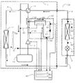
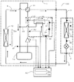
- FIG. 1 It is a schematic block diagram which shows an example of the apparatus structure of the air conditioning apparatus which concerns on Embodiment 1 of this invention. It is a figure which shows the flow of the refrigerant
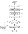
- FIG. 10 is a ph diagram for illustrating processing of a composition determination function unit 40B in the first embodiment. It is a figure of the flowchart which shows the process of the control action of the control apparatus. It is a figure of the flowchart which shows the process operation procedure of the composition determination function part 40B which concerns on Embodiment 2 of this invention.
- FIG. 10 is a ph diagram for explaining processing of a composition determination function unit 40B in the second embodiment. It is a figure of the flowchart which shows the process operation procedure of the composition determination function part 40B which concerns on Embodiment 3 of this invention.
- FIG. 10 is a ph diagram for explaining processing of a composition determination function unit 40B in the second embodiment.
- FIG. 1 is a schematic configuration diagram illustrating an example of a device configuration of an air-conditioning apparatus (hereinafter, referred to as an air-conditioning apparatus 100) according to Embodiment 1. Based on FIG. 1, the structure of the air conditioning apparatus 100 is demonstrated. Here, the levels of temperature, pressure, and the like are not particularly determined in relation to absolute values, but are relatively determined in terms of the state and operation of the apparatus.
- the air-conditioning apparatus 100 of the present embodiment is a non-azeotropic refrigerant mixture composed of a plurality of refrigerants having different boiling points (for example, a refrigerant in which R32 refrigerant and R1234yf refrigerant are mixed in a mass ratio of 44 wt% (weight percent) and 56 wt%. ) Is circulated and performs air conditioning using a refrigeration cycle.
- the outdoor unit 1 and the indoor unit 2 are connected by the refrigerant main pipe 3, and the refrigerant circuit is comprised.
- the operation mode a cooling operation mode in which the indoor unit 2 to be operated cools or a heating operation mode in which the indoor unit 2 performs heating can be selected.
- the outdoor unit 1 includes a compressor 10, a refrigerant flow switching device 11 such as a four-way valve, an outdoor heat exchanger 12, and an accumulator 13, and each device is connected by a refrigerant pipe 4.
- the compressor 10 sucks a low-temperature and low-pressure refrigerant, compresses the refrigerant, and discharges it in a high-temperature and high-pressure state.
- the compressor 10 does not specifically limit, For example, it is good to comprise the compressor 10 with the inverter compressor etc. which can control capacity
- the refrigerant flow switching device 11 is a device that switches between a refrigerant flow in the cooling operation mode and a refrigerant flow in the heating operation mode.
- the outdoor heat exchanger 12 functions as a condenser during the cooling operation and functions as an evaporator during the heating operation, and exchanges heat between the air supplied from the outdoor fan (blower) 12A and the refrigerant.
- the outdoor fan 12 ⁇ / b> A supplies air to the outdoor heat exchanger 12 in order to promote heat exchange between the refrigerant and the air in the outdoor heat exchanger 12.
- the outdoor fan 12 ⁇ / b> A can change the rotational speed based on the control of the control device 40.
- the accumulator 13 is provided on the suction side of the compressor 10 and stores surplus refrigerant generated due to a difference in the operation state between the cooling operation and the heating operation or surplus refrigerant with respect to a transient operation change.
- the air conditioner 100 is provided with a composition detection circuit 20 for the main refrigerant circuit.
- the composition detection circuit 20 includes a first pipe 21, a second pipe 22, a composition detection heat exchanger 23, and a second expansion device 24.
- the first pipe 21 is a pipe that branches off from the refrigerant pipe 4 that connects the discharge unit of the compressor 10 and the refrigerant flow switching device 11 and bypasses part of the refrigerant discharged from the compressor 10.
- the second pipe 22 is a pipe that branches from the refrigerant pipe 4 that connects the refrigerant flow switching device 11 and the accumulator 13 and joins the refrigerant that flows on the suction side of the compressor 10.
- the composition detection heat exchanger 23 exchanges heat between the refrigerant flowing through the first pipe 21 and the refrigerant flowing through the second pipe 22.
- the second expansion device 24 is provided between the composition detection heat exchanger 23 and the second pipe 22.
- the second throttle device 24 is illustrated as a capillary tube in FIG. 1, the pressure of the refrigerant is reduced, such as a fixed throttle pressure reducing valve based on another principle, or an electronic expansion valve driven by a stepping motor to change the opening degree. As long as it is inflated, any device may be used.
- the outdoor unit 1 includes a first pressure detection device 30 and a second pressure detection device 31 as pressure detection devices (pressure sensors).
- the first pressure detection device 30 serving as a high pressure detection device is provided in the refrigerant pipe 4 that connects the compressor 10 and the refrigerant flow switching device 11, and is a high temperature and high pressure refrigerant that is compressed and discharged by the compressor 10. pressure is detected as the detection value P 1 (the high pressure).
- the second pressure detection device 31 serving as the low pressure detection device is provided in the refrigerant pipe 4 that connects the refrigerant flow switching device 11 and the accumulator 13, and the pressure (low pressure) of the low-temperature and low-pressure refrigerant sucked by the compressor 10. and detects the pressure) as a detection value P 2.
- the composition detection circuit 20 includes a first temperature detection device 32 and a second temperature detection device 33 as temperature detection devices (temperature sensors).
- the first temperature detection device 32 serving as the supercooled liquid temperature detection device is provided in the first pipe 21 connected to the upstream side of the second expansion device 24, and is connected to the composition detection heat exchanger 23. Temperatur of the effluent was high pressure subcooled liquid refrigerant is detected as the detection value T 1 (the supercooled liquid refrigerant temperature).
- the second temperature detection device 33 serving as a two-phase refrigerant temperature detection device is provided in the second pipe 22 connected to the downstream side of the second expansion device 24, and the pressure is reduced by the second expansion device 24.
- the first temperature detection device 32 and the second temperature detection device 33 may be configured by a thermistor, for example.
- the air conditioner 100 of the present embodiment has the control device 40 in the outdoor unit 1.
- the control device 40 performs processing based on, for example, an instruction input from a remote controller, detection values related to detection by various detection devices, and the like, and controls devices that constitute the air conditioning device 100.
- the device control is, for example, control of the frequency of the compressor 10, the rotational speed (including ON / OFF) of the outdoor fan 12 ⁇ / b> A, switching of the refrigerant flow switching device 11, opening degree of the first expansion device 51, and the like.
- the control device 40 of the present embodiment particularly has a composition calculation function unit 40A and a composition determination function unit 40B.
- Composition calculating function section 40A the detection of the detection value T 2 and the second pressure detecting device 31 according to the detection of at least the first detection value T 1 and the second of the detection of the temperature detecting device 32 of the temperature sensing device 33 the detection value P 2 according performs a process for calculating the composition of the refrigerant components in the mixture refrigerant circulating in the refrigerant circuit.
- the composition determination function unit 40 ⁇ / b> B is based on the detection value T 1 related to the detection of the first temperature detection device 32 and the detection value P 1 related to the detection of the first pressure detection device 31.
- the refrigerant on the downstream side of the second expansion device 24 Determine if the composition is in a detectable state. Then, the compressor 10 and / or outdoor based whether the determination result composition or detectable states by the calculation results of the composition by composition calculating function unit 40A and composition determining function unit 40B as well as the detected value P 1 and the detection value P 2
- the rotational speed of the fan 12A is controlled.
- the outdoor unit 1 is provided with the control device 40, but the indoor unit 2 may be provided. Further, each of the outdoor unit 1 and the indoor unit 2 may be provided.
- control device 40 this can be configured only by a dedicated device (hardware). Further, for example, hardware may be configured by arithmetic control means (computer) centering on a CPU (Central Processing Unit). Then, the processing procedures performed by the composition calculation function unit 40A, the composition determination function unit 40B, etc. are programmed in advance and stored as software, firmware, etc., for example, in the storage means of the control device 40, and the calculation control means stores the program. By executing, the processing of each unit may be performed.
- the indoor unit 2 is equipped with a load side heat exchanger 50 and a first expansion device 51.
- the indoor unit 2 is connected to the outdoor unit 1 through the refrigerant main pipe 3 so that the refrigerant flows in and out.
- the load-side heat exchanger 50 for example, performs heat exchange between air supplied from an indoor fan (not shown) and a refrigerant, and generates heating air or cooling air to be supplied to the air-conditioning target space. It is.
- the first expansion device 51 has a function as a pressure reducing valve or an expansion valve, and decompresses the refrigerant to expand it.
- the first expansion device 51 may be configured by an electronic expansion valve or the like that can variably control the opening degree.
- the indoor unit 2 detects the temperature of the refrigerant flowing out from the load-side heat exchanger 50 and the third temperature detecting device 60 for detecting the temperature of the refrigerant flowing into the load-side heat exchanger 50 during the cooling operation.
- the third temperature detection device 60 is provided in a pipe connecting the first expansion device 51 and the load side heat exchanger 50, and the fourth temperature detection device 61 is first with respect to the load side heat exchanger 50.
- the fifth temperature detector 62 is provided in the air suction portion of the load-side heat exchanger 50.
- Each temperature detection device may be constituted by a thermistor, for example.
- FIG. 2 is a diagram illustrating the refrigerant flow when the air-conditioning apparatus 100 is in the cooling operation mode.
- the flow direction of the refrigerant is indicated by solid arrows.
- the cooling operation mode will be described by taking as an example a case where a cooling load is generated in the load-side heat exchanger 50.
- the low-temperature and low-pressure refrigerant is compressed by the compressor 10 and discharged as a high-temperature and high-pressure gas refrigerant.
- the high-temperature and high-pressure gas refrigerant discharged from the compressor 10 is divided into a refrigerant flowing through the main refrigerant circuit flowing into the refrigerant flow switching device 11 and a refrigerant bypassing the first pipe 21.
- the refrigerant flowing through the main refrigerant circuit flows into the outdoor heat exchanger 12 via the refrigerant flow switching device 11.
- the high-temperature and high-pressure gas refrigerant that has flowed into the outdoor heat exchanger 12 is condensed while radiating heat to the outdoor air, and becomes high-pressure liquid refrigerant.
- the high-pressure liquid refrigerant that has flowed out of the outdoor heat exchanger 12 flows out of the outdoor unit 1, passes through the refrigerant main pipe 3, and flows into the indoor unit 2.
- the high-pressure liquid refrigerant that has flowed into the indoor unit 2 is decompressed to a low-temperature and low-pressure two-phase refrigerant by the first expansion device 51, and then flows into the load-side heat exchanger 50 that acts as an evaporator and absorbs heat from the indoor air.
- the indoor air is cooled and becomes a low-temperature and low-pressure gas refrigerant.
- the low-temperature and low-pressure gas refrigerant that has flowed out of the load-side heat exchanger 50 flows into the outdoor unit 1 through the refrigerant main pipe 3.
- the refrigerant flowing into the outdoor unit 1 passes through the refrigerant flow switching device 11 and the accumulator 13 and is sucked into the compressor 10.
- control device 40 includes the refrigerant saturation temperature calculated from the pressure associated with the detection by the second pressure detection device 31, the composition of the refrigerant passing through the composition detection circuit 20, and the fourth temperature detection device 61.
- the degree of opening of the first expansion device 51 is controlled so that the superheat (degree of superheat) obtained as a difference from the temperature related to the detection of is constant.
- the high-temperature and high-pressure gas refrigerant discharged from the compressor 10 divided into the first pipe 21 flows into the composition detection heat exchanger 23.
- the high-temperature and high-pressure gas refrigerant that has flowed into the composition detection heat exchanger 23 radiates heat to the low-temperature and low-pressure two-phase refrigerant that has been decompressed by the second expansion device 24, thereby becoming a high-pressure supercooled liquid refrigerant. Flows into the device 24.
- the pressure is reduced to a low-temperature and low-pressure two-phase refrigerant by the second expansion device 24, and then flows into the composition detection heat exchanger 23 again, and absorbs heat from the high-temperature and high-pressure gas refrigerant flowing through the first pipe 21. It becomes a low-pressure gas refrigerant.
- the low-pressure gas refrigerant that has passed through the composition detection heat exchanger 23 passes through the second pipe 22 and joins the refrigerant pipe 4 on the upstream side of the accumulator 13.
- FIG. 3 is a diagram illustrating the refrigerant flow when the air-conditioning apparatus 100 is in the heating operation mode.
- the flow direction of the refrigerant is indicated by solid arrows.
- the heating operation mode will be described by taking as an example a case where a thermal load is generated in the load-side heat exchanger 50.
- the low-temperature and low-pressure refrigerant is compressed by the compressor 10 and discharged as a high-temperature and high-pressure gas refrigerant.
- the high-temperature and high-pressure gas refrigerant discharged from the compressor 10 is divided into a refrigerant flowing through the main refrigerant circuit flowing into the refrigerant flow switching device 11 and a refrigerant bypassing the first pipe 21.
- the refrigerant flowing through the main refrigerant circuit flows into the indoor unit 2 through the refrigerant main pipe 3 via the refrigerant flow switching device 11.
- the high-temperature high-pressure gas refrigerant that has flowed into the indoor unit 2 radiates heat to the indoor air in the load-side heat exchanger 50, becomes high-pressure liquid refrigerant, and flows into the first expansion device 51. Then, after the pressure is reduced to the low-temperature and low-pressure two-phase refrigerant by the first expansion device 51, the indoor unit 2 flows out, passes through the refrigerant main pipe 3, and flows into the outdoor unit 1.
- the low-temperature and low-pressure two-phase refrigerant that has flowed into the outdoor unit 1 absorbs heat from outdoor air in the outdoor heat exchanger 12 and becomes a low-temperature and low-pressure gas refrigerant.
- the low-temperature and low-pressure gas refrigerant exiting the outdoor heat exchanger 12 passes through the refrigerant flow switching device 11 and the accumulator 13 and is sucked into the compressor 10.
- control device 40 includes the saturation temperature of the refrigerant calculated from the pressure associated with the detection by the first pressure detection device 30, the composition of the refrigerant passing through the composition detection circuit 20, and the third temperature detection device 60.
- the degree of opening of the first expansion device 51 is controlled so that the subcool (degree of supercooling) obtained as the difference from the temperature related to the detection of is constant.
- a part of the high-temperature and high-pressure gas refrigerant discharged from the compressor 10 divided into the first pipe 21 has the same flow as in the cooling operation mode.
- the refrigerant divided into the first pipe 21 flows in the order of the composition detection heat exchanger 23, the second expansion device 24, the composition detection heat exchanger 23, and the second pipe 22, and in the upstream portion of the accumulator 13. Merges with main refrigerant.
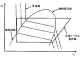
- FIG. 4 is a ph diagram of a non-azeotropic refrigerant mixture. Since the non-azeotropic refrigerant mixture is composed of a plurality of refrigerant components having different boiling points, the temperature of the saturated liquid refrigerant and the temperature of the saturated gas refrigerant at the same pressure are different. For this reason, given the pressure, temperature, and composition of the mixed refrigerant, there is a characteristic that the state of the refrigerant is determined at one point even in the two-phase state.
- FIG. 5 is a flowchart showing a processing operation procedure of the mixed refrigerant composition calculation function unit 40A.
- processing in the composition calculation function unit 40A of the control device 40 will be described.
- step A1 the detection values T 1 , T 2 , and P 2 are input from the first temperature detection device 32, the first temperature detection device 33, and the second pressure detection device 31, respectively.
- step A2 each component of the mixed refrigerant in step A2, it is assumed that the circulating composition X i.
- the suffix i indicates that the composition is related to the i components of the mixed refrigerant.
- the composition calculating function unit 40A of the control unit 40 the supercooled liquid enthalpy H 1 of the high pressure step A3 is calculated by Equation (1). Further, the enthalpy H 2 of the low-pressure refrigerant in step A4 is calculated by the equation (2).
- H 1 H 1 (T 1 , X i ) (1)
- H 2 H 2 (T 2 , P 2 , X i ) (2)
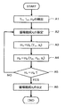
- FIG. 6 is a flowchart showing a processing operation procedure of the composition determination function unit 40B in the first embodiment.
- processing in the composition determination function unit 40B of the control device 40 will be described.
- step B1 the detection values T 1 , T 2 , P of the first temperature detection device 32, the second temperature detection device 33, the first pressure detection device 30, and the second pressure detection device 31 are detected. 1, reads the P 2.
- step B2 the filling composition of the mixed refrigerant set to a predetermined value (composition when the refrigerant is filled in the refrigerant circuit) Y i is read from the storage means.
- the suffix i indicates that the composition is related to the i components of the mixed refrigerant.
- Step B3 from the filling composition Y i read in Step B2 and the detection values T 1 and P 1 relating to the detection of the first temperature detection device 32 and the first pressure detection device 30, the second A high-pressure supercooled liquid enthalpy F 1 in the upstream portion of the expansion device 24 is calculated. Further, in step B4, from the detection value P 1 of the detection of the fill composition Y i and the first pressure detector 30 read in step B2, the high-pressure saturated liquid enthalpy at pressure upstream of the second throttle device 24 F L1 is calculated.
- step B7 it is determined whether the high-pressure supercooled liquid enthalpy F 1 is smaller than the high-pressure saturated liquid enthalpy F L1 and the low-pressure refrigerant enthalpy F 2 is larger than the low-pressure saturated liquid enthalpy F L2. I do. If it determines with satisfy
- the composition determining function unit 40B of the control device 40 the supercooled liquid enthalpy F 1 of the high pressure step B3 is calculated by Equation (3) below.
- enthalpy F L1 of the low-pressure refrigerant in step B4 is calculated by Equation (4) below.
- the low-pressure saturated liquid enthalpy F L2 in step B6 is calculated by Equation (5) below.
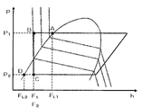
- FIG. 7 is a ph diagram for explaining the processing of the composition determination function unit 40B in the first embodiment.
- the process in the composition determination function unit 40B of the control device 40 in the present embodiment described above will be described based on a specific example.
- the filling composition Y R32 of R32 in the mixed refrigerant is 44 wt%.
- the detection value P 1 related to detection by the first pressure detection device 30 is 2.7 MPa abs
- the detection value P 2 related to detection by the second pressure detection device 31 is 0.70 MPa abs .
- the detection value T 1 related to detection by the first temperature detection device 32 is 45 ° C.
- the detection value T 2 related to detection by the second temperature detection device 33 is 2 ° C.
- values described in REFPROP Version 9.0 released by NIST National Institute of Standards and Technology
- the value T 1 45 ° C.
- the high-pressure supercooled liquid enthalpy F 1 196 kJ / kg.
- the high-pressure supercooled liquid enthalpy F 1 corresponds to the enthalpy at point B on the ph diagram of FIG.
- the high-pressure saturated liquid enthalpy F L1 207 kJ / kg.
- saturated liquid enthalpy F L1 of the high pressure corresponds to the enthalpy at point A on the diagram p-h line in FIG.
- the enthalpy F 2 of the low-pressure refrigerant corresponds to the enthalpy at the point C on the ph diagram of FIG.
- the low-pressure saturated liquid enthalpy F L2 120 kJ / kg.
- saturated liquid enthalpy F L2 of the low pressure corresponds to the enthalpy at point D on the diagram p-h line in FIG.
- step B7 comparing the supercooled liquid enthalpy F 1 and the high-pressure saturated liquid enthalpy F L1 in step B7. Further comparing the saturated liquid enthalpy F L2 enthalpy F 2 and the low pressure of the low pressure refrigerant.
- step B8 the composition calculation result is set to “positive”.
- the determination formula F 1 ⁇ F L1 and F 2 > F L2 when no margin is added is changed to the form F 1 ⁇ F L1 ⁇ ⁇ and F 2 > F L2 ⁇ ⁇ .
- ⁇ and ⁇ are margins on the high-pressure side and the low-pressure side, respectively, and by defining them as values satisfying ⁇ ⁇ 1 and ⁇ > 1, point A in FIG. 7 is moved to the left side and point D is moved to the right side. As a result, it is possible to make a correct / incorrect determination of the composition calculation result on the more stable side.
- the isotherm in the supercooled liquid state is substantially parallel to the axis representing the pressure. This represents a feature that the temperature does not change much even if the pressure changes. Therefore, if the data representing the relationship between the temperature, the composition, and the supercooled liquid enthalpy is prepared so as to have the same value regardless of the pressure, the amount of data can be reduced. Further, it is preferable to interpolate the stored data on the relationship between temperature, pressure, and composition as necessary to calculate the enthalpy.
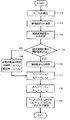
- FIG. 8 is a flowchart showing a control operation process of the control device 40. Processing of device control operation by the control device 40 in the present embodiment will be described. First reads the detection values P 1 and P 2 according to the detection of the first pressure detector 30 and the second pressure detector 31 in step C1. Next, in step C2, as described above, it calculates the circulating composition X i by composition calculating function unit 40A.
- step C3 the composition determination function unit 40B performs correct / incorrect determination regarding the composition calculation result.
- step C4 it is determined whether or not the correct / incorrect determination result regarding the composition calculation result is “correct”. If it is determined that the correct / incorrect determination result regarding the composition calculation result is “correct”, the calculated circulation composition X i is adopted as correct (step C5). On the other hand, if it is determined that the correct / incorrect determination result regarding the composition calculation result is “incorrect”, the calculated circulation composition X i does not reflect the actual circulation composition.
- a predetermined value (in the cooling operation mode: X ci and in the heating operation mode: X hi ) set in advance according to the operation mode is adopted as the circulation composition X i (step C6).
- the cooling operation mode accumulates the refrigerant in the outdoor heat exchanger 12, the accumulator 13 excess refrigerant is hardly accumulated in, the circulating composition in operation a value close to the filling composition Y i. Therefore, the predetermined value X ci in the cooling operation mode is set as the filling composition Y i .
- the predetermined value X hi in the heating operation mode is set to a value such that the proportion of components having a boiling point lower than that of the filling composition Y i is increased.
- step C7 it calculates the condensing temperature T c from the detection value P 1 Metropolitan according to the detection of the circulating composition X i and the first pressure detector 30. Further, the evaporation temperature Te is calculated from the circulation composition X i and the detection value P 2 related to the detection by the second pressure detection device 31.
- the condensation temperature Tc and the evaporation temperature Te data representing the relationship between the pressure, the composition, and the saturation temperature is stored in a storage means (not shown) in a table format, and the composition and the pressure are stored.
- the saturation temperature can be derived from the detection value of the detection device.
- [Delta] T e is a value obtained by subtracting the target value T em evaporation temperature from the condenser temperature T is a value obtained by subtracting the target value T cm of the condensing temperature from c [Delta] T c and the evaporation temperature T e calculate.
- the condensing temperature T c and the evaporation temperature T e is used the value calculated in step C7.
- the condensation temperature target value Tcm and the evaporation temperature target value Tem values stored in a storage means (not shown) as data according to the outdoor temperature and the indoor temperature are used.
- step C9 as [Delta] T c and [Delta] T e approaches 0 (zero), and the frequency f of the compressor 10, the control of the rotational speed F of the outdoor fan 12A.
- the outdoor heat exchanger 12 functions as a condenser
- ⁇ T c is a positive value
- the frequency f of the compressor 10 is decreased or / and the rotational speed F of the outdoor fan 12A is increased.
- ⁇ T c is a negative value
- control is performed such that the frequency f of the compressor 10 is increased and / or the rotational speed F of the outdoor fan 12A is decreased.
- the outdoor-side heat exchanger 12 may serve as an evaporator
- [Delta] T e is when the positive value to reduce the rotational speed of the rotational speed F of the frequency f is increased and / or the outdoor fan 12A of the compressor 10 Perform such control.
- ⁇ T e is a negative value
- control is performed to decrease the frequency f of the compressor 10 and / or increase the rotation speed F of the outdoor fan 12A.
- a predetermined value set in advance is set. by the values to be adopted as the circulating compositions X i, can be controlled based on the appropriate circulation composition, it is possible to obtain the operation efficient air conditioner. For this reason, energy saving can be achieved.
- the a predetermined value X hi in the heating operation with a predetermined value X ci during cooling operation to set each it is possible to perform control based on more appropriate circulation composition.
- Embodiment 2 an air conditioner 100 according to Embodiment 2 of the present invention will be described. Here, parts different from the first embodiment will be mainly described.
- the configuration of the air-conditioning apparatus 100 of the second embodiment is the same as that of the first embodiment.
- the air conditioning apparatus 100 according to the second embodiment is different from the air conditioning apparatus 100 according to the first embodiment in the processing in the composition determination function unit 40B of the control device 40.
- the saturation temperature on the high-pressure side and the low-pressure side is calculated for the composition determination function unit 40B. Then, the magnitude relationship between the calculated value of the saturated liquid temperature, the detection value T 1 related to the detection by the first temperature detection device 32, and the detection value T 2 related to the detection by the second temperature detection device 33 is compared. It is determined whether or not the circulation composition calculated by the calculation function unit 40A is correct.
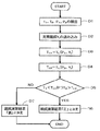
- FIG. 9 is a flowchart showing a processing operation procedure of the composition determination function unit 40B in the second embodiment.
- the operation of the composition determination function unit 40B in the present embodiment will be described.
- step D1 the first temperature detection device 32, the second temperature detection device 33, the first pressure detection device 30 and the second pressure detection device 31 respectively detect the detected values T 1 , T 2 , Read P 1 and P 2 .
- step D2 is set to a predetermined value, it reads the filling composition Y i of the mixed refrigerant that has been stored.
- the suffix i indicates that the composition is related to the i components of the mixed refrigerant.
- the second throttle device of the high pressure in the upstream portion of 24 the saturated liquid temperature T L1 is calculated. Further, a low-pressure saturated liquid temperature T L2 in the downstream portion of the second expansion device 24 is calculated from the filling composition Y i read in step D2 and the detection value P2 of the second pressure detection device 31 in step D4. .
- the detection value T 1 according to the detection of the first temperature detector 32 at step D5 is smaller than the saturated liquid temperature T L1 of the high pressure and the detected value T 2 according to the detection of the second temperature detector 33 Is determined to be higher than the low-pressure saturated liquid temperature T L2 . If it determines with satisfy
- the high-pressure saturated liquid temperature T L1 in step D3 is calculated by the following equation (6). Further, the saturated liquid temperature T L2 of the low pressure step D4 is calculated by Equation (7) shown below.
- T L1 T L (P 1 , Y i ) (6)
- T L2 T L (P 2 , Y i ) (7)
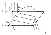
- FIG. 10 is a ph diagram for explaining the processing of the composition determination function unit 40B in the second embodiment.
- the process in the composition determination function unit 40B of the control device 40 in the present embodiment described above will be described based on a specific example.
- the filling composition Y R32 of R32 in the mixed refrigerant is 44 wt%.
- the detection value P 1 related to detection by the first pressure detection device 30 is 2.7 MPa abs
- the detection value P 2 related to detection by the second pressure detection device 31 is 0.70 MPa abs .
- the detection value T 1 related to detection by the first temperature detection device 32 is 45 ° C.
- the detection value T 2 related to detection by the second temperature detection device 33 is 2 ° C.
- the detection value T 1 45 ° C.
- the detection value T 1 according to the detection of the first temperature detecting device 32 corresponds to the temperature at point B in FIG. 10.
- the detection value T 2 according to the detection of the second temperature detecting device 33 corresponds to the temperature of the point C in FIG. 10.
- the high-pressure saturated liquid temperature T L1 50 ° C.
- the high-pressure saturated liquid temperature T L1 corresponds to the temperature at the point A on the ph diagram of FIG.
- step D5 comparing the detected value T 1 and the high-pressure saturated liquid temperature T L1 according to the detection of the first temperature detecting device 32 in step D5. Also, comparing the saturated liquid temperature T L2 detected value T 2 and the low-pressure according to the detection of the second temperature detector 33.
- T 1 45 ° C.
- ⁇ T L1 50 ° C.
- step D6 the composition calculation result is determined as “positive”.
- the judgment formula T 1 ⁇ T L1 and T 2 > T L2 when no margin is added is changed to the form T 1 ⁇ T L1 ⁇ ⁇ and T 2 > T L2 ⁇ ⁇ .
- ⁇ and ⁇ are margins on the high-pressure side and the low-pressure side, respectively, and by defining them as values satisfying ⁇ ⁇ 1 and ⁇ > 1, point A in FIG. 10 is moved to the left side and point D is moved to the right side. As a result, it is possible to make a correct / incorrect determination of the composition calculation result on the more stable side.
- the margin ⁇ value on the high-pressure side is too small, the area where the calculation result is determined to be erroneous increases even though the composition calculation result is positive.
- the margin ⁇ on the low-pressure side is too large, the region in which the calculation result is determined to be erroneous increases even though the composition calculation result is positive. Therefore, the margins ⁇ and ⁇ on the high-pressure side and the low-pressure side need to be determined in consideration of the error due to the composition, the error due to the temperature detection device, and the error due to the pressure detection device.
- the composition determination function unit 40B calculates the composition calculation function unit 40A based on the high-pressure saturated liquid temperature T L1 and the low-pressure saturated liquid temperature T L2. Since the result is determined, the processing procedure can be reduced and the control based on the circulation composition can be performed more easily.
- Embodiment 3 an air conditioner 100 according to Embodiment 3 of the present invention will be described. Here, a different part from Embodiment 1 and Embodiment 2 is mainly demonstrated.
- the configuration of the air-conditioning apparatus 100 of the second embodiment is the same as that of the first embodiment.
- the air conditioner 100 according to the third embodiment is different from the air conditioner 100 according to the first and second embodiments in the process related to the determination in the composition determining function unit 40B of the control device 40.
- the detected value and the refrigerant filling composition Y relating to the detection by the first pressure detection device 30, the second pressure detection device 31, the first temperature detection device 32, and the second temperature detection device 33 are described. i is used to calculate the dryness of the refrigerant in the upstream and downstream portions of the second expansion device 24. Then, by determining whether the refrigerant state is a two-phase state or a liquid state, it is determined whether the calculated circulation composition of the refrigerant is correct.
- FIG. 11 is a flowchart showing a processing operation procedure of the composition determination function unit 40B in the third embodiment.
- the operation of the composition determination function unit 40B in the present embodiment will be described.
- the first temperature detection device 32, the second temperature detection device 33, the first pressure detection device 30 and the second pressure detection device 31 respectively detect the detected values T 1 , T 2 , Read P 1 and P 2 .
- step E2 and set to a predetermined value, it reads the filling composition Y i of the mixed refrigerant that has been stored.
- the suffix i indicates that the composition is related to the i components of the mixed refrigerant.
- step E5 it is the dryness X 1 of the refrigerant 0 or less at the upstream portion of the second throttling device 24 in step E5, and than the dryness X 2 is 0 of the refrigerant at the downstream part of the second throttling device 24 Judge whether it is large. If it is determined that the determination condition is satisfied, the composition calculation result is determined to be “positive” (step E6). If it is determined that the determination condition is not satisfied, the composition calculation result is determined to be “false” (step E7).
- the dryness X 1 of the refrigerant in the upstream portion of the second throttling device 24 calculates the equation (8) shown below.
- the dryness X 2 of the refrigerant in the downstream portion of the second throttling device 24 is calculated from the equation (9).
- the high-pressure saturated gas enthalpy F G1 included in the formulas (8) and (9) is calculated from the detection value P 1 related to the detection by the first pressure detection device 30 and the charging composition Y i of the mixed refrigerant ( 10).
- the low pressure saturated gas enthalpy F G2 calculated by filling the composition Y i Tokara type detection value P 2 and mixed refrigerant according to the detection of the second pressure detector 31 (11).
- Other definitions of enthalpy are those described in the first embodiment.
- FIG. 12 is a ph diagram for explaining the processing of the composition determination function unit 40B in the second embodiment.
- the process in the composition determination function unit 40B of the control device 40 in the present embodiment described above will be described based on a specific example.
- the filling composition Y R32 of R32 in the mixed refrigerant is 44 wt%.
- the detection value P 1 related to detection by the first pressure detection device 30 is 2.7 MPa abs
- the detection value P 2 related to detection by the second pressure detection device 31 is 0.70 MPa abs .
- the detection value T 1 related to detection by the first temperature detection device 32 is 45 ° C.
- the detection value T 2 related to detection by the second temperature detection device 33 is 2 ° C.
- the detection value T 1 45 ° C.
- the dryness X 1 of the refrigerant in the upstream portion of the second throttling device 24 corresponds to the dryness fraction at point B on the diagram p-h line in FIG.
- the dryness X 2 is 0.35.
- the dryness X 2 of the refrigerant in the downstream portion of the second throttling device 24 corresponds to the dryness fraction at point C on the diagram p-h line in FIG.
- step E5 if the dryness X 1 of the refrigerant is 0 or less at the upstream portion of the second throttling device 24 in step E5, and the dryness X 2 of the refrigerant in the downstream portion of the second throttling device 24 is greater than 0 Determine whether.
- the composition is erroneously detected by adding a margin that allows for an error to the determination formula of the correct / incorrect determination performed by the composition determination function unit 40B. The possibility of doing so can be reduced.
- the determination formula X 1 ⁇ 0 and X 2 > 0 when no margin is added is changed to the form X 1 ⁇ 0 + ⁇ and X 2 > 0 + ⁇ .
- ⁇ and ⁇ are margins on the high-pressure side and the low-pressure side, respectively, and are defined as values satisfying ⁇ ⁇ 0 and ⁇ > 0, thereby moving point A in FIG. 10 to the left side and point D to the right side.
- the margin ⁇ value on the high-pressure side is too small, the area where the calculation result is determined to be erroneous increases even though the composition calculation result is positive.
- the margin ⁇ on the low-pressure side is too large, the region in which the calculation result is determined to be erroneous increases even though the composition calculation result is positive. Therefore, the margins ⁇ and ⁇ on the high-pressure side and the low-pressure side need to be determined in consideration of the error due to the composition, the error due to the temperature detection device, and the error due to the pressure detection device.
- the composition determination function unit 40B is based on the dryness X 1 and X 2 of the refrigerant in the upstream portion and the downstream portion of the second expansion device 24. Since the calculation result of the composition calculation function unit 40A is determined, the processing procedure can be reduced, and the control based on the circulation composition can be performed more easily.
- Embodiment 4 FIG.
- the air conditioner 100 shown in FIG. 1 an example in which one indoor unit 2 and the outdoor unit 1 are connected via the refrigerant main pipe 3 is illustrated.
- the number of connected devices is not limited to one, and a plurality of devices may be connected.
- a plurality of outdoor units 1 may be connected.
- a representative outdoor unit may be determined.
- the air conditioning apparatus 100 of Embodiment 1 etc. mentioned above demonstrated to the example the direct expansion circuit by which the outdoor unit 1 and the indoor unit 2 were connected in series by the refrigerant
- a heat medium converter having a heat exchanger between heat medium that exchanges heat between the mixed refrigerant and a heat medium different from the mixed refrigerant and the first expansion device 51 is provided at a position away from the outdoor unit 1. .
- coolant may be sufficient.
- Embodiment 1 and the like described above a description has been given of an example of a refrigerant in which R32 refrigerant is mixed at a mass ratio of 44 wt% and R1234yf refrigerant at a mass ratio of 56 wt%, but the present invention is not limited to this. If it is a non-azeotropic mixed refrigerant in which a plurality of refrigerants are mixed and the temperatures of the saturated gas and the saturated liquid are different at the same pressure, the type and mixing ratio of the refrigerants to be mixed are different from the mixed refrigerants described in the above embodiments. The same effect is produced.
- the outdoor unit 1 has one compressor 10 has been described.
- the outdoor unit 1 having a plurality of compressors may be used.
- the outdoor unit 1 has one accumulator 13 has been described, but a plurality of accumulators 13 may be provided.
- the circulation composition of the mixed refrigerant flowing through the refrigerant circuit may change due to factors such as accumulation of refrigerant in the indoor unit 2 stopped by the air conditioner 100 to which a plurality of indoor units 2 are connected. Therefore, the same effect can be obtained even when the outdoor unit 1 is not equipped with the accumulator 13.
- the air conditioner 100 having the refrigerant flow switching device 11 in the outdoor unit 1 has been described as an example.
- the refrigerant flow switching device 11 is not provided, and the cooling operation or heating is performed.
- the present invention can also be applied to the air conditioner 100 that performs only one of the operations.
- the air conditioner 100 which has the composition detection circuit 20 in the outdoor unit 1 was demonstrated to the example, it does not restrict to this.
- High pressure which is upstream pressure of the first expansion device 51
- low pressure which is downstream pressure
- the composition detection circuit 20 is not necessarily provided.
- the low-pressure pressure that is the pressure on the downstream side of the first expansion device 51 can be substituted if it is a value close to that.
- the pressure on the suction side of the compressor 10 or the pressure on the suction side of the accumulator 13 can be used instead.
Landscapes
- Engineering & Computer Science (AREA)
- Physics & Mathematics (AREA)
- Mechanical Engineering (AREA)
- Thermal Sciences (AREA)
- General Engineering & Computer Science (AREA)
- Air Conditioning Control Device (AREA)
- Compression-Type Refrigeration Machines With Reversible Cycles (AREA)
Abstract
Description
図1は、実施の形態1に係る空気調和装置(以下、空気調和装置100と称する)の装置構成の一例を示す概略構成図である。図1に基づいて、空気調和装置100の構成について説明する。ここで、温度、圧力等の高低については、特に絶対的な値との関係で高低等が定まっているものではなく、装置等における状態、動作等において相対的に定まるものとする。
室外機1は、圧縮機10、四方弁等の冷媒流路切替装置11、室外側熱交換器12およびアキュムレータ13を有し、各機器を冷媒配管4で接続している。
室内機2は、負荷側熱交換器50と、第一の絞り装置51とを搭載している。室内機2は、冷媒主管3を介して室外機1と接続し、冷媒が流入出するようになっている。負荷側熱交換器50は、たとえば室内ファン(図示省略)から供給される空気と冷媒との間で熱交換を行ない、空調対象空間に供給するための暖房用空気または冷房用空気を生成するものである。また、第一の絞り装置51は減圧弁や膨張弁としての機能を有し、冷媒を減圧して膨張させるものである。例えば開度を可変に制御可能な電子式膨張弁等により、第一の絞り装置51を構成するとよい。
図2は、空気調和装置100の冷房運転モード時における冷媒の流れを示す図である。図2では冷媒の流れ方向を実線矢印で示している。この図2では、負荷側熱交換器50で冷熱負荷が発生している場合を例に冷房運転モードについて説明する。
図3は、空気調和装置100の暖房運転モード時における冷媒の流れを示す図である。図3では冷媒の流れ方向を実線矢印で示している。この図3では、負荷側熱交換器50で温熱負荷が発生している場合を例に暖房運転モードについて説明する。
次にこの発明の実施の形態2の空気調和装置100について説明する。ここでは、実施の形態1と異なる部分を主に説明する。ここで、実施の形態2の空気調和装置100の構成は実施の形態1と同じである。実施の形態2の空気調和装置100は、制御装置40の組成判定機能部40Bにおける処理が実施の形態1の空気調和装置100と異なる。
次にこの発明の実施の形態3の空気調和装置100について説明する。ここでは、実施の形態1および実施の形態2と異なる部分を主に説明する。ここで、実施の形態2の空気調和装置100の構成は実施の形態1と同じである。実施の形態3の空気調和装置100は、制御装置40の組成判定機能部40Bにおいて判定に係る処理が実施の形態1および実施の形態2の空気調和装置100と異なる。
例えば、図1に示す空気調和装置100では、冷媒主管3を介して1台の室内機2と室外機1とを接続して構成している場合を例に示しているが、室内機2の接続台数を1台に限定するものではなく、複数台接続するようにしてもよい。
Claims (9)
- 沸点の異なる複数の成分を含む非共沸混合冷媒を吐出する圧縮機と、
空調対象空間外の空気と前記冷媒の熱交換を行う室外側熱交換器と、
前記冷媒の圧力調整をする第一の絞り装置と、
前記空調対象空間の空気と前記冷媒の熱交換を行う負荷側熱交換器と
を冷媒配管で接続して冷媒回路を構成する空気調和装置であって、
前記冷媒回路を循環する前記冷媒における各成分の組成の値を表す循環組成を演算する処理を行う組成演算機能部と、
該組成演算機能部の演算結果が正しいかどうかを判定し、正しくないと判定すると、あらかじめ設定した組成に係る所定値を循環組成として採用し、正しいと判定すると、前記演算結果を循環組成として採用する処理を行う組成判定機能部とを有する制御装置を備える空気調和装置。 - 冷房運転における前記所定値と暖房運転における前記所定値とを設定し、
前記冷房運転時の所定値は、前記冷媒回路に充填した冷媒の組成と等しい値に設定し、
前記暖房運転時の所定値は、前記冷媒回路に充填した冷媒の組成よりも、前記複数の成分のうち、沸点が低い成分の割合が多くなるような値に設定する請求項1に記載の空気調和装置。 - 前記冷媒回路における高圧側の過冷却液状態の冷媒の温度を過冷却液冷媒温度として検出する過冷却液温度検出装置と、
前記過冷却液状態の前記冷媒の高圧圧力を検出する高圧圧力検出装置と、
前記過冷却液状態の冷媒を減圧した後の二相状態の冷媒温度を検出する二相冷媒温度検出装置と、
前記過冷却液状態の冷媒を減圧した後の冷媒の低圧圧力を検出する低圧圧力検出装置とをさらに備え、
前記組成演算機能部は、前記過冷却液温度、前記二相冷媒温度および前記低圧圧力に基づいて前記循環組成を演算する処理を行い、
前記組成判定機能部は、前記過冷却液冷媒温度、前記高圧圧力、前記二相冷媒温度および前記低圧圧力に基づいて前記組成演算機能部の演算結果が正しいかどうかを判定する処理を行うことを特徴とする請求項1または2に記載の空気調和装置。 - 前記組成判定機能部は、あらかじめ記憶させておいた圧力と温度と前記混合冷媒の組成に対する過冷却液エンタルピの関係と前記過冷却液温度と前記高圧圧力と前記混合冷媒の充填時の組成とから高圧過冷却液冷媒エンタルピを演算し、前記高圧過冷却液冷媒エンタルピを低圧二相冷媒エンタルピと等しいとし、あらかじめ定めた圧力と前記冷媒の組成とに対する飽和液エンタルピの関係と前記高圧圧力および前記低圧圧力と前記混合冷媒の充填時の組成とに基づいて、高圧飽和液エンタルピおよび低圧飽和液エンタルピとを演算し、前記高圧過冷却冷媒エンタルピが前記高圧飽和液エンタルピよりも小さく、かつ、前記低圧二相冷媒エンタルピが前記低圧飽和液エンタルピよりも大きいと判断すると、前記組成演算機能部の演算結果が正しいと判定する請求項3に記載の空気調和装置。
- 前記組成判定機能部は、あらかじめ定めた圧力と前記冷媒の組成とに対する飽和液温度の関係と前記高圧圧力および前記低圧圧力と前記混合冷媒の充填時の組成とに基づいて、高圧飽和液温度および低圧飽和液温度を演算し、前記過冷却冷媒温度が前記高圧飽和液温度よりも小さく、かつ、前記二相冷媒温度が前記低圧飽和液温度よりも大きいと判断すると、前記組成演算機能部の演算結果が正しいと判定する請求項3に記載の空気調和装置。
- 前記組成判定機能部は、あらかじめ定めた圧力と温度と前記冷媒の組成とに対する前記混合冷媒の乾き度の関係と前記過冷却液冷媒温度と前記高圧圧力と前記混合冷媒の充填時の組成とから高圧過冷却冷媒乾き度を演算し、あらかじめ定めた圧力と温度と前記冷媒の組成とに対する前記混合冷媒の乾き度の関係と前記二相冷媒温度と前記低圧圧力と前記混合冷媒の充填時の組成とから低圧二相冷媒乾き度を演算し、前記高圧過冷却冷媒乾き度が0以下であり、かつ、前記低圧二相冷媒乾き度が0よりも大きいと判断すると、前記組成演算機能部の演算結果が正しいと判定する請求項3に記載の空気調和装置。
- 前記組成判定機能部は、前記混合冷媒の組成と前記混合冷媒の充填時の組成との違いおよび/または前記過冷却液温度検出装置と前記高圧圧力検出装置と前記二相冷媒温度検出装置と前記低圧圧力検出装置の各検出誤差によるパラメータの計算結果のずれによる誤判定を回避するためのマージンを持たせた判定を行う請求項3~6のいずれか一項に記載の空気調和装置。
- 前記室外側熱交換器に前記外気を送り込む室外ファンをさらに備え、
前記制御装置は、前記採用した循環組成に基づいて、前記圧縮機の周波数または/および前記室外ファンの回転数を制御する請求項3~7のいずれか一項に記載の空気調和装置。 - 冷媒回路内において前記圧縮機の吸入側に、余剰冷媒を溜めるアキュムレータをさらに備え、
前記圧縮機と前記冷媒流路切替装置との間の流路に接続され、前記圧縮機の吐出冷媒の一部をバイパスさせる第一の配管と、
前記冷媒流路切替装置と前記アキュムレータとの間の流路に接続され前記第一の配管に分流した冷媒を前記圧縮機の吸入冷媒に合流させる第二の配管と、
前記第一の配管を流れる冷媒を減圧して前記第二の配管に流す第二の絞り装置と、
前記第一の配管を流れる冷媒と前記前記第三の絞り装置から流出する冷媒とを熱交換させる組成検知用熱交換器と
を有する組成検知回路を構成し、
前記組成検知回路上に、前記過冷却液温度検出装置、前記二相冷媒温度検出装置、前記高圧圧力検出装置、前記低圧圧力検出装置とを設置する請求項3~8のいずれか一項に記載の空気調和装置。
Priority Applications (4)
| Application Number | Priority Date | Filing Date | Title |
|---|---|---|---|
| PCT/JP2012/003078 WO2013168199A1 (ja) | 2012-05-11 | 2012-05-11 | 空気調和装置 |
| JP2014514234A JP5818979B2 (ja) | 2012-05-11 | 2012-05-11 | 空気調和装置 |
| EP12876165.7A EP2878899B1 (en) | 2012-05-11 | 2012-05-11 | Air conditioner |
| US14/394,280 US9851134B2 (en) | 2012-05-11 | 2012-05-11 | Air-conditioning apparatus |
Applications Claiming Priority (1)
| Application Number | Priority Date | Filing Date | Title |
|---|---|---|---|
| PCT/JP2012/003078 WO2013168199A1 (ja) | 2012-05-11 | 2012-05-11 | 空気調和装置 |
Publications (1)
| Publication Number | Publication Date |
|---|---|
| WO2013168199A1 true WO2013168199A1 (ja) | 2013-11-14 |
Family
ID=49550286
Family Applications (1)
| Application Number | Title | Priority Date | Filing Date |
|---|---|---|---|
| PCT/JP2012/003078 Ceased WO2013168199A1 (ja) | 2012-05-11 | 2012-05-11 | 空気調和装置 |
Country Status (4)
| Country | Link |
|---|---|
| US (1) | US9851134B2 (ja) |
| EP (1) | EP2878899B1 (ja) |
| JP (1) | JP5818979B2 (ja) |
| WO (1) | WO2013168199A1 (ja) |
Cited By (4)
| Publication number | Priority date | Publication date | Assignee | Title |
|---|---|---|---|---|
| JP2015132422A (ja) * | 2014-01-14 | 2015-07-23 | 三菱電機株式会社 | 冷凍装置 |
| WO2015114774A1 (ja) * | 2014-01-30 | 2015-08-06 | 三菱電機株式会社 | 冷凍サイクル装置、空気調和装置、及び、冷凍サイクル装置における循環組成の算出方法 |
| WO2019082331A1 (ja) * | 2017-10-26 | 2019-05-02 | 三菱電機株式会社 | 冷凍空調装置及び制御装置 |
| JPWO2019058450A1 (ja) * | 2017-09-20 | 2020-10-15 | 三菱電機株式会社 | 冷凍機 |
Families Citing this family (3)
| Publication number | Priority date | Publication date | Assignee | Title |
|---|---|---|---|---|
| DK181305B1 (en) | 2019-01-15 | 2023-08-07 | Maersk Container Ind A/S | CALIBRATION OF COOLANT SATURATION TEMPERATURE IN A COOLING SYSTEM |
| ES2998559T3 (en) * | 2019-09-12 | 2025-02-20 | Carrier Corp | Diagnostic for refrigerant composition verification |
| GB2616477A (en) * | 2022-03-11 | 2023-09-13 | Edwards Vacuum Llc | Refrigerant testing |
Citations (6)
| Publication number | Priority date | Publication date | Assignee | Title |
|---|---|---|---|---|
| JPH08121881A (ja) * | 1994-10-19 | 1996-05-17 | Sanyo Electric Co Ltd | 蒸気圧縮式冷凍機 |
| JPH0968356A (ja) * | 1995-06-23 | 1997-03-11 | Mitsubishi Electric Corp | 冷媒循環システム |
| JPH1163747A (ja) * | 1997-08-20 | 1999-03-05 | Mitsubishi Electric Corp | 冷凍空調装置および冷凍空調装置の冷媒組成を求める方法 |
| JPH11182951A (ja) * | 1997-12-25 | 1999-07-06 | Mitsubishi Electric Corp | 冷凍装置 |
| JP2001141322A (ja) * | 1999-11-12 | 2001-05-25 | Matsushita Refrig Co Ltd | ヒートポンプ装置 |
| JP2003314914A (ja) | 2002-04-24 | 2003-11-06 | Mitsubishi Electric Corp | 冷媒循環システム |
Family Cites Families (3)
| Publication number | Priority date | Publication date | Assignee | Title |
|---|---|---|---|---|
| JP3211405B2 (ja) * | 1992-10-01 | 2001-09-25 | 株式会社日立製作所 | 冷媒組成検出装置 |
| US5626026A (en) * | 1994-07-21 | 1997-05-06 | Mitsubishi Denki Kabushiki Kaisha | Control-information detecting apparatus for a refrigeration air-conditioner using a non-azeotrope refrigerant |
| JP2000141322A (ja) * | 1998-11-10 | 2000-05-23 | Misawa Homes Co Ltd | 木質様樹脂成形品及び木質様樹脂成形品の製造方法 |
-
2012
- 2012-05-11 US US14/394,280 patent/US9851134B2/en not_active Expired - Fee Related
- 2012-05-11 JP JP2014514234A patent/JP5818979B2/ja not_active Expired - Fee Related
- 2012-05-11 EP EP12876165.7A patent/EP2878899B1/en not_active Not-in-force
- 2012-05-11 WO PCT/JP2012/003078 patent/WO2013168199A1/ja not_active Ceased
Patent Citations (6)
| Publication number | Priority date | Publication date | Assignee | Title |
|---|---|---|---|---|
| JPH08121881A (ja) * | 1994-10-19 | 1996-05-17 | Sanyo Electric Co Ltd | 蒸気圧縮式冷凍機 |
| JPH0968356A (ja) * | 1995-06-23 | 1997-03-11 | Mitsubishi Electric Corp | 冷媒循環システム |
| JPH1163747A (ja) * | 1997-08-20 | 1999-03-05 | Mitsubishi Electric Corp | 冷凍空調装置および冷凍空調装置の冷媒組成を求める方法 |
| JPH11182951A (ja) * | 1997-12-25 | 1999-07-06 | Mitsubishi Electric Corp | 冷凍装置 |
| JP2001141322A (ja) * | 1999-11-12 | 2001-05-25 | Matsushita Refrig Co Ltd | ヒートポンプ装置 |
| JP2003314914A (ja) | 2002-04-24 | 2003-11-06 | Mitsubishi Electric Corp | 冷媒循環システム |
Non-Patent Citations (1)
| Title |
|---|
| "REFPROP Version9.0 sold", NATIONAL INSTITUTE OF STANDARDS AND TECHNOLOGY |
Cited By (7)
| Publication number | Priority date | Publication date | Assignee | Title |
|---|---|---|---|---|
| JP2015132422A (ja) * | 2014-01-14 | 2015-07-23 | 三菱電機株式会社 | 冷凍装置 |
| WO2015114774A1 (ja) * | 2014-01-30 | 2015-08-06 | 三菱電機株式会社 | 冷凍サイクル装置、空気調和装置、及び、冷凍サイクル装置における循環組成の算出方法 |
| GB2534789A (en) * | 2014-01-30 | 2016-08-03 | Mitsubishi Electric Corp | Refrigeration cycle device, air conditioning device, and method for calculating circulation composition in refrigeration cycle device |
| GB2534789B (en) * | 2014-01-30 | 2020-03-11 | Mitsubishi Electric Corp | Refrigeration cycle apparatus, air-conditioning apparatus, and method for calculating circulation composition in refrigeration cycle apparatus |
| JPWO2019058450A1 (ja) * | 2017-09-20 | 2020-10-15 | 三菱電機株式会社 | 冷凍機 |
| WO2019082331A1 (ja) * | 2017-10-26 | 2019-05-02 | 三菱電機株式会社 | 冷凍空調装置及び制御装置 |
| JPWO2019082331A1 (ja) * | 2017-10-26 | 2020-04-02 | 三菱電機株式会社 | 冷凍空調装置及び制御装置 |
Also Published As
| Publication number | Publication date |
|---|---|
| JP5818979B2 (ja) | 2015-11-18 |
| EP2878899A4 (en) | 2016-03-30 |
| US20150075194A1 (en) | 2015-03-19 |
| EP2878899A1 (en) | 2015-06-03 |
| JPWO2013168199A1 (ja) | 2015-12-24 |
| US9851134B2 (en) | 2017-12-26 |
| EP2878899B1 (en) | 2018-10-24 |
Similar Documents
| Publication | Publication Date | Title |
|---|---|---|
| CN103180676B (zh) | 制冷循环装置及制冷循环控制方法 | |
| US8353173B2 (en) | Refrigerating cycle apparatus and operation control method therefor | |
| JP5818979B2 (ja) | 空気調和装置 | |
| US9303908B2 (en) | Air conditioner | |
| JP5791716B2 (ja) | 冷凍空調装置及び冷凍空調装置の制御方法 | |
| US10082324B2 (en) | Refrigeration apparatus having leakage or charge deficiency determining feature | |
| CN103221761B (zh) | 空调热水供给复合系统 | |
| EP2955462B1 (en) | Heat pump apparatus | |
| JP5094801B2 (ja) | 冷凍サイクル装置及び空気調和装置 | |
| JP4093275B2 (ja) | 空気調和装置 | |
| CN100545551C (zh) | 空调机的过热度控制系统及其方法 | |
| JP6067178B2 (ja) | 熱源側ユニット及び空気調和装置 | |
| WO2012090579A1 (ja) | 熱源システムおよびその制御方法 | |
| JP5479625B2 (ja) | 冷凍サイクル装置及び冷凍サイクル制御方法 | |
| GB2563162A (en) | Air conditioner | |
| JP5881339B2 (ja) | 空気調和機 | |
| JP5369953B2 (ja) | 多室型空気調和装置の性能計算装置 | |
| JP6072311B2 (ja) | 冷凍サイクル装置、空気調和装置、及び、冷凍サイクル装置における循環組成の算出方法 | |
| JP2007225140A (ja) | ターボ冷凍機およびその制御装置ならびにターボ冷凍機の制御方法 | |
| JP5424705B2 (ja) | 冷凍空気調和装置 | |
| JP2007255738A (ja) | 空気調和装置 | |
| JP2007163102A (ja) | 空気調和装置 | |
| JP2017194222A (ja) | 空気調和機及び冷媒量判定方法 | |
| WO2024252470A1 (ja) | 冷凍サイクル装置 | |
| WO2017179166A1 (ja) | 空気調和装置 |
Legal Events
| Date | Code | Title | Description |
|---|---|---|---|
| 121 | Ep: the epo has been informed by wipo that ep was designated in this application |
Ref document number: 12876165 Country of ref document: EP Kind code of ref document: A1 |
|
| WWE | Wipo information: entry into national phase |
Ref document number: 14394280 Country of ref document: US |
|
| ENP | Entry into the national phase |
Ref document number: 2014514234 Country of ref document: JP Kind code of ref document: A |
|
| NENP | Non-entry into the national phase |
Ref country code: DE |
|
| WWE | Wipo information: entry into national phase |
Ref document number: 2012876165 Country of ref document: EP |