WO2013168232A1 - 内燃機関 - Google Patents
内燃機関 Download PDFInfo
- Publication number
- WO2013168232A1 WO2013168232A1 PCT/JP2012/061760 JP2012061760W WO2013168232A1 WO 2013168232 A1 WO2013168232 A1 WO 2013168232A1 JP 2012061760 W JP2012061760 W JP 2012061760W WO 2013168232 A1 WO2013168232 A1 WO 2013168232A1
- Authority
- WO
- WIPO (PCT)
- Prior art keywords
- oil
- intake pipe
- pipe
- gas
- tubular member
- Prior art date
- Legal status (The legal status is an assumption and is not a legal conclusion. Google has not performed a legal analysis and makes no representation as to the accuracy of the status listed.)
- Ceased
Links
Images







Classifications
-
- F—MECHANICAL ENGINEERING; LIGHTING; HEATING; WEAPONS; BLASTING
- F01—MACHINES OR ENGINES IN GENERAL; ENGINE PLANTS IN GENERAL; STEAM ENGINES
- F01M—LUBRICATING OF MACHINES OR ENGINES IN GENERAL; LUBRICATING INTERNAL COMBUSTION ENGINES; CRANKCASE VENTILATING
- F01M13/00—Crankcase ventilating or breathing
- F01M13/04—Crankcase ventilating or breathing having means for purifying air before leaving crankcase, e.g. removing oil
-
- F—MECHANICAL ENGINEERING; LIGHTING; HEATING; WEAPONS; BLASTING
- F01—MACHINES OR ENGINES IN GENERAL; ENGINE PLANTS IN GENERAL; STEAM ENGINES
- F01M—LUBRICATING OF MACHINES OR ENGINES IN GENERAL; LUBRICATING INTERNAL COMBUSTION ENGINES; CRANKCASE VENTILATING
- F01M13/00—Crankcase ventilating or breathing
- F01M13/02—Crankcase ventilating or breathing by means of additional source of positive or negative pressure
- F01M13/028—Crankcase ventilating or breathing by means of additional source of positive or negative pressure of positive pressure
-
- F—MECHANICAL ENGINEERING; LIGHTING; HEATING; WEAPONS; BLASTING
- F02—COMBUSTION ENGINES; HOT-GAS OR COMBUSTION-PRODUCT ENGINE PLANTS
- F02M—SUPPLYING COMBUSTION ENGINES IN GENERAL WITH COMBUSTIBLE MIXTURES OR CONSTITUENTS THEREOF
- F02M35/00—Combustion-air cleaners, air intakes, intake silencers, or induction systems specially adapted for, or arranged on, internal-combustion engines
- F02M35/10—Air intakes; Induction systems
- F02M35/10209—Fluid connections to the air intake system; their arrangement of pipes, valves or the like
- F02M35/10222—Exhaust gas recirculation [EGR]; Positive crankcase ventilation [PCV]; Additional air admission, lubricant or fuel vapour admission
-
- F—MECHANICAL ENGINEERING; LIGHTING; HEATING; WEAPONS; BLASTING
- F04—POSITIVE - DISPLACEMENT MACHINES FOR LIQUIDS; PUMPS FOR LIQUIDS OR ELASTIC FLUIDS
- F04D—NON-POSITIVE-DISPLACEMENT PUMPS
- F04D17/00—Radial-flow pumps, e.g. centrifugal pumps; Helico-centrifugal pumps
- F04D17/08—Centrifugal pumps
- F04D17/10—Centrifugal pumps for compressing or evacuating
-
- F—MECHANICAL ENGINEERING; LIGHTING; HEATING; WEAPONS; BLASTING
- F04—POSITIVE - DISPLACEMENT MACHINES FOR LIQUIDS; PUMPS FOR LIQUIDS OR ELASTIC FLUIDS
- F04D—NON-POSITIVE-DISPLACEMENT PUMPS
- F04D29/00—Details, component parts, or accessories
- F04D29/26—Rotors specially for elastic fluids
- F04D29/28—Rotors specially for elastic fluids for centrifugal or helico-centrifugal pumps for radial-flow or helico-centrifugal pumps
- F04D29/284—Rotors specially for elastic fluids for centrifugal or helico-centrifugal pumps for radial-flow or helico-centrifugal pumps for compressors
-
- F—MECHANICAL ENGINEERING; LIGHTING; HEATING; WEAPONS; BLASTING
- F04—POSITIVE - DISPLACEMENT MACHINES FOR LIQUIDS; PUMPS FOR LIQUIDS OR ELASTIC FLUIDS
- F04D—NON-POSITIVE-DISPLACEMENT PUMPS
- F04D29/00—Details, component parts, or accessories
- F04D29/70—Suction grids; Strainers; Dust separation; Cleaning
- F04D29/701—Suction grids; Strainers; Dust separation; Cleaning especially adapted for elastic fluid pumps
-
- F—MECHANICAL ENGINEERING; LIGHTING; HEATING; WEAPONS; BLASTING
- F04—POSITIVE - DISPLACEMENT MACHINES FOR LIQUIDS; PUMPS FOR LIQUIDS OR ELASTIC FLUIDS
- F04D—NON-POSITIVE-DISPLACEMENT PUMPS
- F04D29/00—Details, component parts, or accessories
- F04D29/70—Suction grids; Strainers; Dust separation; Cleaning
- F04D29/701—Suction grids; Strainers; Dust separation; Cleaning especially adapted for elastic fluid pumps
- F04D29/705—Adding liquids
-
- F—MECHANICAL ENGINEERING; LIGHTING; HEATING; WEAPONS; BLASTING
- F01—MACHINES OR ENGINES IN GENERAL; ENGINE PLANTS IN GENERAL; STEAM ENGINES
- F01M—LUBRICATING OF MACHINES OR ENGINES IN GENERAL; LUBRICATING INTERNAL COMBUSTION ENGINES; CRANKCASE VENTILATING
- F01M13/00—Crankcase ventilating or breathing
- F01M13/02—Crankcase ventilating or breathing by means of additional source of positive or negative pressure
- F01M13/021—Crankcase ventilating or breathing by means of additional source of positive or negative pressure of negative pressure
- F01M2013/027—Crankcase ventilating or breathing by means of additional source of positive or negative pressure of negative pressure with a turbo charger or compressor
-
- F—MECHANICAL ENGINEERING; LIGHTING; HEATING; WEAPONS; BLASTING
- F01—MACHINES OR ENGINES IN GENERAL; ENGINE PLANTS IN GENERAL; STEAM ENGINES
- F01M—LUBRICATING OF MACHINES OR ENGINES IN GENERAL; LUBRICATING INTERNAL COMBUSTION ENGINES; CRANKCASE VENTILATING
- F01M13/00—Crankcase ventilating or breathing
- F01M13/04—Crankcase ventilating or breathing having means for purifying air before leaving crankcase, e.g. removing oil
- F01M2013/0422—Separating oil and gas with a centrifuge device
Definitions
- the present invention relates to an internal combustion engine, and more particularly to an internal combustion engine provided with a blow-by gas recirculation mechanism.
- Patent Document 1 discloses a first PCV pipe that connects a cylinder head and an intake pipe downstream of a throttle valve, and a second PCV pipe that connects the cylinder head and an intake pipe upstream of a compressor.
- a blowby gas recirculation mechanism is disclosed. According to the blow-by gas recirculation mechanism of Patent Document 1, the blow-by gas can be reintroduced into the internal combustion engine and combusted through two paths of the first PCV pipe and the second PCV pipe.
- Japanese Unexamined Patent Publication No. 2009-293464 Japanese Unexamined Patent Publication No. 2009-281317 Japanese Unexamined Patent Publication No. 2004-116292 Japanese Unexamined Patent Publication No. 2009-264158 Japanese Unexamined Patent Publication No. 2005-048734
- blow-by gas contains soot derived from carbon-based fuel and oil in the crankcase. Most of this oil is present in the blow-by gas with the soot incorporated therein. Therefore, when blow-by gas is introduced, soot-containing oil contacts and adheres to the intake pipe inner wall and other intake system components, and as a result, changes to deposits and deposits. Deposit accumulation leads to a reduction in intake performance and thus engine performance. Therefore, it is desirable that the generation of soot-containing oil can be suppressed.
- Patent Document 1 a removal device for removing oil in blow-by gas is provided in the second PCV pipe.
- a removal device for removing oil in blow-by gas
- soot-containing oil flows into the intake pipe.
- an oil mist having a particle size of 1 ⁇ m or less hereinafter referred to as “small particle size oil mist”
- small particle size oil mist has a property that it is difficult to be captured by a removing device and is easily vaporized because of its small particle size. Therefore, when soot-containing oil flows into the intake pipe as a small particle size oil mist and comes into contact with or adheres to the inner wall of the intake pipe or the like, it changes to deposit with a high probability.
- further improvements were necessary.
- an object of the present invention is to provide an internal combustion engine that can suppress generation or accumulation of deposits derived from oil mist.
- a first invention is an internal combustion engine, A PCV pipe for introducing blow-by gas containing oil into the intake pipe of the internal combustion engine; Enlarged oil distribution means for enlarging the particle size of the oil in the blow-by gas introduced from the PCV pipe to the intake pipe and distributing the expanded oil along the inner peripheral wall of the intake pipe When, It is characterized by providing.
- the second invention is the first invention, wherein
- the large particle size oil circulation means includes an intake pipe inner member having a curved outer peripheral wall disposed on a blow-by gas passage through which blow-by gas introduced into the intake pipe flows.
- the PCV pipe is connected to the intake pipe from above in the vertical direction, The opening of the PCV pipe to the intake pipe and the outer peripheral wall are arranged to face each other.
- the third invention is the second invention, wherein
- the compressor further includes a compressor connected to the intake pipe downstream of the intake pipe inner member and compressing a gas flowing through the intake pipe.
- 4th invention is 2nd or 3rd invention
- Fluidity lowering means for reducing fluidity on the outer peripheral wall of the oil in the blow-by gas introduced into the intake pipe is provided on the outer peripheral wall.
- the fifth invention is the fourth invention, wherein
- the fluidity reducing means is a plurality of means extending in the upstream and downstream direction of the intake pipe and spaced apart in the circumferential direction of the outer peripheral wall.
- An EGR pipe for introducing EGR gas into the intake pipe from the upstream side of the opening of the PCV pipe to the intake pipe;
- the intake pipe inner member is an internal pipe having a smaller diameter than the intake pipe, The upstream end opening of the internal pipe opens toward the opening of the EGR pipe to the intake pipe.
- the oil in the blow-by gas can be circulated along the inner peripheral wall of the intake pipe while enlarging the particle diameter by the oil sizing means for increasing the particle size.
- the oil mist in the blow-by gas is increased in viscosity by losing the oil component in the blow-by gas, and is easily attached when contacting the inner wall of the intake pipe.
- the particle size of the oil can be increased by the oil distribution means for increasing the particle size, the speed of increasing the viscosity can be slowed down. Therefore, adhesion of oil mist to the inner wall of the intake pipe can be suppressed. Therefore, according to the first invention, it is possible to suppress the generation of deposits.
- the oil having a large particle diameter and having a large oil particle diameter can take oil having a small particle diameter into the oil. For this reason, if the oil having a large particle size flows along the inner peripheral wall of the intake pipe, the oil adhering to the passage and depositing can be uniformly washed and removed. Therefore, according to the first aspect, deposit accumulation can be suppressed.
- the blow-by gas can flow along the outer peripheral wall.
- the PCV pipe is connected to the intake pipe from above in the vertical direction, and further, the opening of the PCV pipe to the intake pipe and the outer peripheral wall are arranged to face each other, so that the oil with a large particle diameter is placed on the outer peripheral wall. It can be generated and distributed uniformly along the outer peripheral wall according to the flow of blowby gas and gravity.
- the intake pipe inner member having a curved outer peripheral wall is disposed on the blow-by gas flow path upstream of the compressor, so that the oil particle diameter is increased. Can be uniformly distributed along the outer peripheral wall and introduced into the compressor. Therefore, it is possible to suppress deposit generation and accumulation inside the compressor.
- the fluidity of the oil on the outer peripheral wall can be lowered by the fluidity lowering means. If the fluidity of the oil can be reduced, the oil particles can be increased in size before contacting the intake pipe inner wall or the like. Therefore, according to the present invention, the oil particle size can be reliably increased.
- the oil having a large particle size circulates along the outer peripheral wall in accordance with the flow of blowby gas and gravity.
- the fluidity reducing means is a plurality of means extending in the upstream and downstream direction of the intake pipe and spaced apart along the outer peripheral wall, the flow direction of the blow-by gas And the mobility in the vertical direction can be balanced. Therefore, the oil having a large particle size can be more uniformly distributed along the outer peripheral wall.
- the EGR gas is introduced into the intake pipe from the upstream side of the blow-by gas.
- the EGR gas is a high-temperature gas
- the upstream end opening of the internal pipe having a smaller diameter than the intake pipe opens toward the opening of the EGR pipe to the intake pipe, so that EGR gas is introduced into the internal pipe. It becomes possible to introduce. Therefore, since mixing of EGR gas and blow-by gas can be prevented, the increase in viscosity of oil mist can be prevented.
- FIG. 2 is a diagram for describing a system configuration according to Embodiment 1.
- FIG. It is a cross-sectional enlarged view of the compressor 12b vicinity of FIG. It is a cross-sectional enlarged view of the compressor 12b vicinity of FIG.
- FIG. 4 is a cross-sectional view taken along the line AA ′ of FIG.
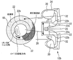
- It is a figure for demonstrating the behavior of the droplet oil 38 inside the compressor 12b. It is a figure for demonstrating the generation
- FIG. 6 is a diagram for explaining the behavior of droplet oil 56 inside the compressor 58.
- FIG. FIG. 6 is a diagram for explaining a modification of the first embodiment. It is a figure for demonstrating the characteristic part of the tubular member in Embodiment 2, and the effect by this characteristic part.
- FIG. 10 is a diagram for explaining a modification of the second embodiment. It is a figure for demonstrating the characteristic part of the tubular member in Embodiment 3, and the effect by this characteristic part. It is a figure for demonstrating the characteristic part of the tubular member in Embodiment 4, and the effect by this characteristic part.
- FIG. 10 is a diagram for explaining a problem of the tubular member 70 according to the third embodiment.
- FIG. 10 is a diagram for explaining a system configuration of a fifth embodiment.
- FIG. 18 is an enlarged cross-sectional view of the vicinity of a compressor 12b in FIG. It is AA 'sectional drawing of FIG. It is a figure showing temperature distribution inside compressor 12b at the time of L
- FIG. 1 is a diagram for explaining a system configuration according to the first embodiment.
- the system of this embodiment includes an engine 10 as an internal combustion engine.
- Each cylinder of the engine 10 is provided with a piston, an intake valve, an exhaust valve, a fuel injector, and the like. Note that the number of cylinders and the cylinder arrangement of the engine 10 are not particularly limited.
- the system of the present embodiment includes a supercharger 12.
- the supercharger 12 includes a turbine 12 a provided in the exhaust pipe 14 and a compressor 12 b provided in the intake pipe 16.
- the turbine 12a and the compressor 12b are connected to each other.
- the turbine 12a rotates by receiving the exhaust pressure, thereby driving the compressor 12b and compressing the gas flowing into the compressor 12b.
- the intake pipe 16 is provided with an intercooler 18 for cooling the compressed gas.
- the system of the present embodiment includes a blow-by gas recirculation mechanism that recirculates the blow-by gas.
- the blow-by gas is a gas that flows into the crankcase from the gap between the piston of the engine 10 and the cylinder wall surface.
- This blow-by gas recirculation mechanism includes a PCV pipe 20.
- the PCV pipe 20 connects the intake pipe 16 upstream of the compressor 12b and a cylinder head cover (not shown) of the engine 10.
- the blow-by gas is reintroduced into the engine 10 by flowing through the PCV pipe 20 and the intake pipe 16 in this order.
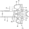
- FIG. 2 is an enlarged cross-sectional view of the vicinity of the compressor 12b of FIG.
- the compressor 12 b includes an impeller 22, a housing 24, and a connecting shaft 26.
- the housing 24 rotatably supports a connecting shaft 26 that supports the impeller 22 so as not to rotate.
- the housing 24 includes an inlet portion 28 that guides intake air to the suction side 22 a of the impeller 22, a spiral scroll 30 disposed on the outer periphery of the impeller 22, and a diffuser 32 that communicates the discharge side 22 b of the impeller 22 and the scroll 30. And are provided.
- the connecting shaft 26 is connected to a turbine wheel (not shown) of the turbine 12a.
- a tubular member 34 is arranged inside the intake pipe 16.
- the tubular member 34 and the intake pipe 16 are arranged so that their central axes coincide.
- a gap 36 is formed between the tubular member 34 and the intake pipe 16.
- the tubular member 34 preferably has an outer diameter of 85% to about 99% of the inner diameter of the intake pipe 16.
- the use of the tubular member 34 having such a size is preferable because it makes it easier for liquid oil (described later) to flow along its outer peripheral wall.
- the downstream end 34 a of the tubular member 34 is disposed so as to face the inlet portion 28.
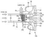
- FIG. 3 is an enlarged cross-sectional view of the vicinity of the compressor 12b of FIG.
- the blow-by gas that has flowed into the intake pipe 16 from the PCV pipe 20 flows toward the inlet portion 28 together with the intake gas flowing through the gap 36.
- the blow-by gas collides with the outer peripheral wall of the tubular member 34, and then flows along the outer peripheral wall of the tubular member 34 (that is, the inner peripheral wall of the intake pipe 16).
- the blow-by gas includes oil mist in which the oil in the crankcase is mist.
- the oil mist here is oil having a particle size of about 5 ⁇ m or less.
- droplet oil 38 a part of oil mist in the collision gas is liquefied.
- the droplet oil 38 successively takes in oil mist in the blow-by gas flowing into the intake pipe 16 and moves on the outer peripheral wall of the tubular member 34 according to the flow of the intake gas and gravity while maintaining the liquefied state.
- the droplet oils 38 a and 38 b shown in FIG. 3 schematically show a temporary liquid pool state of the droplet oil 38.
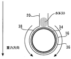
- FIG. 4 is a cross-sectional view taken along the line AA ′ of FIG.
- the PCV pipe 20 is connected to the intake pipe 16 from above in the gravity direction (that is, above in the vertical direction). Therefore, the droplet oil 38 generated by the collision of the blow-by gas flows down the outer peripheral wall of the tubular member 34 according to gravity, and diffuses to the entire outer peripheral wall while maintaining a liquefied state.
- FIG. 5 is a diagram for explaining the behavior of the droplet oil 38 inside the compressor 12b.
- the droplet oil 38 diffuses over the entire outer peripheral wall of the tubular member 34 while maintaining a liquefied state. Therefore, the droplet oil 38 flows from the inlet portion 28 while maintaining this liquefied state, uniformly flows into the surface of the impeller 22, and is discharged to the scroll 30 side. Therefore, according to the intake system structure of FIG. 2, it is possible to uniformly clean the surface of the diffuser 32 with the droplet oil 38 kept in a liquefied state, thereby suppressing the generation or accumulation of deposits on the surface. .
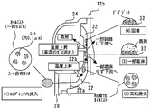
- FIG. 6 is a diagram for explaining a deposit generation mechanism.
- blow-by gas contains oil in the crankcase. And this oil contains a lot of oil mist. This is because the blow-by gas immediately after discharging the cylinder head is hot, and a part of the oil in the blow-by gas exists in a gaseous state and is misted during the circulation of the PCV pipe 20.
- soot-containing oil in which soot having a particle size of about 0.1 ⁇ m is taken.
- the oil mist shown in FIG. 6 schematically shows such a soot-containing oil.
- the soot-containing oil flows into the compressor 12b from the inlet 28 (FIG. 6 (1)).
- the particle size of the soot-containing oil is about 5 ⁇ m or less.
- the gas flowing into the compressor 12b that is, the gas including the suction gas and the blow-by gas
- the temperature rises further in the compression region. For this reason, the internal temperature of the soot-containing oil increases as the temperature of the internal inflowing gas increases. Therefore, the soot-containing oil loses its internal oil component due to evaporation and gradually becomes smaller in particle size.
- the soot-containing oil loses the oil component by evaporation due to the high temperature of the internal inflow gas, thereby reducing the particle size and increasing the viscosity (FIG. 6 (2)). ).
- the soot-containing oil having a reduced particle size and increased viscosity flows on the surface of the diffuser 32 or flows further downstream without landing (FIG. 6 (3)).
- the soot-containing oil that has flowed further downstream loses most of the oil component inside (FIG. 6 (4)).
- the soot-containing oil adheres to the surface of the diffuser 32 and deposits.
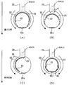
- FIG. 7 is a diagram for explaining the behavior of oil mist in the diffuser 32.
- the oil mist (soot-containing oil) loses its internal oil component to reduce the particle size.
- the fluidity of the oil mist is lost during the circulation and deposits are formed (FIG. 7A).
- the fluidity of the oil mist is kept high and passes through the diffuser 32 and reaches the scroll 30 side (FIG. 7B). From this, it can be seen that if the oil particle size is large, landing on the surface of the diffuser 32 and the like can be avoided, and depositing can be suppressed.
- FIG. 8 is a diagram for explaining the behavior of a large particle size oil mist (referred to as an oil mist having a particle size larger than 1 ⁇ m; hereinafter the same) in the diffuser 32.
- an oil mist having a particle size larger than 1 ⁇ m hereinafter the same
- FIG. 8 shows that when the large particle size oil mist (oil mist A) flows in from the diffuser 32 inlet, it comes into contact with the oil mist (oil mist B) that has already landed on the diffuser 32 surface (FIG. 8 ( 1)). Then, the oil mist B is taken into the oil mist A and becomes an oil mist C having a larger particle size (FIG. 8 (2)). And the oil mist C flows to the diffuser 32 exit, maintaining fluidity (FIG. 8 (3)). From this, it is also understood that the oil mist having a large particle diameter can remove the oil mist that has been deposited or the like.
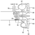
- FIG. 9 is a view for explaining the flow of blow-by gas or the like in the conventional intake system structure.
- the conventional intake system structure is the same as the intake system structure of the present embodiment except that the tubular member 34 is not installed. Therefore, the detailed description regarding the component of FIG. 9 shall be abbreviate
- the blow-by gas that has flowed into the intake pipe 52 from the PCV pipe 50 flows toward the inlet 54 together with the intake gas flowing through the intake pipe 52.
- blow-by gas collides with the inner peripheral wall of the intake pipe 52.
- a part of the oil mist in the blow-by gas becomes a liquefied state (droplet oil 56).
- the droplet oil 56 successively takes in the oil mist in the blow-by gas that has flowed into the intake pipe 52 and moves toward the inlet 54 according to the flow of the intake gas while maintaining the liquefied state.
- FIG. 10 is a diagram for explaining the behavior of the droplet oil 56 inside the compressor 58.
- the droplet oil 56 moves toward the inlet 54 according to the flow of the suction gas while maintaining the liquefied state. Therefore, the droplet oil 56 that has flowed from the inlet portion 54 flows from a part of the surface of the impeller 60 and is discharged to the diffuser 64 side. Accordingly, as shown in FIG. 10, the surface of the diffuser 64 is cleaned along the locus drawn by the droplet oil 56. In other words, in the intake system structure of FIG. 9, the surface of the diffuser 64 can be cleaned only partially.
- the droplet oil 38 described with reference to FIGS. 3 to 5 is an aggregate of oil mist having a particle size far larger than that of the large particle size oil mist. Therefore, oil mist and deposits deposited on the surface of the impeller 22 by the droplet oil 38 can be washed uniformly. Therefore, according to the intake system structure of FIG. 2, deposit accumulation on the entire surface of the diffuser 32 can be suppressed. Further, the droplet oil 38 can reach the scroll 30 side without landing on the surface of the diffuser 32. Therefore, according to the intake system structure of FIG. 2, it is possible to suppress the occurrence of deposits on the entire surface of the diffuser 32.
- FIG. 11 is a diagram for explaining a modification of the first embodiment.
- a tubular member 40 having a shape in which a lower portion in the gravity direction of the tubular member 34 is cut out is used, and a blow-by gas is caused to collide with the tubular member 40 to generate droplet oil 38. It can also be distributed along the wall (FIG. 11A).
- the gas throttle member (liquefaction promoting member) 41 provided at the outlet of the PCV pipe 20 on the intake pipe 16 side and the vertically lower part of the tubular member 34 are cut out larger than the cutout of the tubular member 40. It can also be used in combination with the tubular member 42 (FIG. 11B). More specifically, the gas throttle member 41 is a truncated conical tubular member, and the end portion having the larger diameter is connected to the connection portion between the PCV pipe 20 and the intake pipe 16 and has a diameter. The smaller end is a member located inside the intake pipe 16.
- a gas collision member (liquefaction promoting member) 43 provided at a connection portion between the PCV pipe 20 and the intake pipe 16 and a tubular member 44 in which the tubular member 34 is cut out from a substantially right half are used in combination.
- the gas collision member 43 is a member that extends from a part of the connection portion between the PCV pipe 20 and the intake pipe 16 toward the central axis of the PCV pipe 20 and toward the inside of the intake pipe 16.
- the tubular member 44 extends from the end of the intake pipe 16 of the gas collision member 43 to the lower area in the vertical direction of the intake pipe 16 along the inner peripheral surface of the intake pipe 16 through the lower side of the opening of the PCV pipe 20. It is an existing member.
- a tubular member 45 having a smaller diameter than the tubular member 40 and a tubular member 46 having a shape in which the upper portion of the tubular member 40 is cut out can be used in combination (FIG. 11D).
- the droplet oils 38c, 38d, 38e, and 38f shown in FIG. 11 schematically show a temporary liquid pool state of the droplet oil 38.
- the tubular member 34 and the intake pipe 16 were arrange
- the tubular member 34 of the first embodiment can be used as long as it is a means capable of flowing along the inner peripheral wall of the intake pipe 16 while increasing the particle size of the oil in the blowby gas. Note that the present modification can be similarly applied to each embodiment described later.
- the intake system structure of the first embodiment can be similarly applied to a system not equipped with a supercharger. That is, in view of the deposit generation mechanism, it can be said that if the soot-containing oil is exposed to a high-temperature environment, it becomes easier to change to a deposit. Therefore, even in a system without a supercharger, if the tubular member 34 of the first embodiment is arranged in the vicinity of the intake valve (for example, the intake manifold or the intake pipe upstream of the intake manifold), the droplet oil 38 causes The vicinity of the intake valve can be cleaned uniformly. Accordingly, it is possible to suppress the generation or accumulation of deposits in the vicinity of the intake valve. Note that the present modification can be similarly applied to each embodiment described later.
- the tubular members 34 and 40, the gas throttle member 41 and the tubular member 42 are combined, the gas collision member 43 and the tubular member 44 are combined, and the tubular members 45 and 46 are combined.
- the combination corresponds to the “large particle size oil distribution means” in the first invention.
- the cross-sectional shape perpendicular to the central axis of the tubular member 34 is a circle, but the cross-sectional shape is an ellipse or a polygon (for example, a pentagon, a hexagon, etc.). May be.
- the tubular members 34, 40, 42, 44, and 45 correspond to the “intake pipe member” in the second invention.
- Embodiment 2 of the present invention will be described with reference to FIGS.
- the present embodiment is characterized in that the tubular member 34 of the first embodiment is replaced with a tubular member 66 shown in FIG. Therefore, in the following, this characteristic part will be mainly described, and the system configuration and other contents already described in the first embodiment will be omitted.
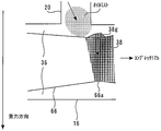
- FIG. 12 is a diagram for explaining the characteristic part of the tubular member according to the second embodiment and the effect of the characteristic part.
- a tubular member 66 is disposed inside the intake pipe 16. Therefore, the droplet oil 38 can be generated on the outer peripheral wall of the tubular member 66.
- the PCV pipe 20 is connected to the intake pipe 16 from above in the gravity direction. Therefore, the generated droplet oil 38 flows down the outer peripheral wall of the tubular member 66 according to gravity, and diffuses over the entire outer peripheral wall while maintaining a liquefied state.
- the tubular member 66 is formed with a tube port restricting portion 66a in the middle thereof. Therefore, it is possible to suppress the movement of the droplet oil 38 in the direction of the compressor 12b in the pipe port restricting portion 66a and to promote the movement in the direction of gravity (the arrow direction in the drawing). As a result, a temporary liquid pool state is generated in the tube opening restricting portion 66a (droplet oil 38g), and the droplet oil 38g can flow along the tube opening restricting portion 66a. Therefore, it is possible to spread the droplet oil 38 over the entire outer peripheral wall of the tubular member 66. In this regard, since the tubular member 34 of the first embodiment is a straight tubular member, the droplet oil 38 may be sucked into the compressor 12b before reaching the entire outer peripheral wall of the tubular member 34.
- the droplet oil 38g in a liquid pool state is caused to flow along the outer periphery of the tube mouth restricting portion 66a, and the droplet oil 38 is applied to the entire outer peripheral wall of the tubular member 66. Can be reliably distributed. Therefore, the droplet oil 38 can be brought into contact with the surface of the diffuser 32 in a more uniform state. Therefore, it is possible to more effectively suppress the generation or deposition of deposits on the surface of the diffuser 32.
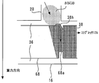
- FIG. 13 is a diagram for explaining a modification of the second embodiment.
- a tubular member 68 in which a groove 68a is formed can be used instead of the tubular member 66.
- the groove 68a is formed so as to go around the outer peripheral wall of the tubular member 68.
- a liquid pool state of the droplet oil 38 is generated in the groove portion 68 a (droplet oil 38 h), and can flow along the groove portion 68 a. Therefore, it is possible to spread the droplet oil 38 over the entire outer peripheral wall of the tubular member 68. Therefore, substantially the same effect as in the second embodiment can be obtained.
- Embodiment 3 FIG. [Features of Embodiment 3]
- Embodiment 3 of the present invention will be described with reference to FIG.
- the present embodiment is characterized in that the tubular member 34 of the first embodiment is replaced with a tubular member 70 shown in FIG. Therefore, in the following, this characteristic part will be mainly described, and the system configuration and other contents already described in the first embodiment will be omitted.
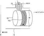
- FIG. 14 is a diagram for explaining the characteristic part of the tubular member according to the third embodiment and the effect of the characteristic part.
- a tubular member 70 is disposed inside the intake pipe 16.
- the tubular member 70 is a straight tubular member similar to the tubular member 34 of FIG. Therefore, droplet oil (not shown) can be generated on the outer peripheral wall of the tubular member 70 and can flow to the outer peripheral wall.
- a coating portion 70a made of a lipophilic material is formed in the middle of the outer peripheral wall of the tubular member 70 (specifically, a portion immediately downstream of the connection port of the PCV pipe 20).
- the coating part 70a is formed so that the outer peripheral wall of the said tubular member 70 may wrap around in a strip
- the movement of the droplet oil in the direction of the compressor 12b in the coating portion 70a can be suppressed, and the movement in the direction of gravity (the arrow direction in the figure) can be promoted.
- the coating part 70a corresponds to the “fluidity lowering means” in the third invention.
- Embodiment 4 FIG. [Features of Embodiment 4]
- a fourth embodiment of the present invention will be described with reference to FIG.
- the present embodiment is characterized in that the tubular member 34 of the first embodiment is replaced with a tubular member 72 shown in FIG. Therefore, in the following, this characteristic part will be mainly described, and the system configuration and other contents already described in the first embodiment will be omitted.
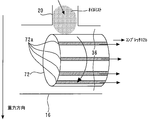
- FIG. 15 is a diagram for explaining the characteristic part of the tubular member according to the fourth embodiment and the effect of the characteristic part.
- a tubular member 72 is disposed inside the intake pipe 16.
- the tubular member 72 is a straight tubular member similar to the tubular member 34 of FIG. Therefore, droplet oil (not shown) can be generated on the outer peripheral wall of the tubular member 72 and can flow to the outer peripheral wall.
- a coating portion 72 a made of a lipophilic material is formed on the outer peripheral wall of the tubular member 72 along the gas flow direction.
- the coating portions 72a are formed at a predetermined interval in the circumferential direction of the tubular member 72, and the outer peripheral wall of the tubular member 72 is exposed between the coating portions 72a. That is, it can be said that the highly lipophilic part (coating part 72a) and the low lipophilic part (the outer peripheral wall of the tubular member 72) are alternately formed on the outer peripheral wall of the tubular member 72.
- tubular member 72 of the present embodiment it is possible to further enhance the effects of the tubular members of the first to third embodiments by combining the highly lipophilic portion and the low lipophilic portion. Become. That is, since the tubular member 34 of the first embodiment is a straight tubular member, the droplet oil 38 may be sucked into the compressor 12b before reaching the entire outer peripheral wall of the tubular member 34. Further, in the tubular members 66, 68, and 70 of the second and third embodiments, the particle diameter of the droplet oil 38 in the liquid reservoir state becomes too large, and the inside of the intake pipe 16 on the side opposite to the PCV pipe 20 connection port is inside. There is a possibility of reaching the peripheral wall.
- FIG. 16 is a diagram for explaining the problem of the tubular member 70 of the third embodiment.
- a coating portion 70 a is formed on the outer peripheral wall of the tubular member 70. Therefore, it is possible to flow the droplet oil 38 along the coating part 70a.
- the droplet oil 38i may accumulate on the inner peripheral wall of the intake pipe 16. Then, since the droplet oil 38i flows into the compressor 12b from a part of the impeller 22, the surface of the diffuser 32 can be cleaned only partially.
- the amount of droplet oil 38i described with reference to FIG. 16 can be reduced by the arrangement of the coating portion 72a described above. Therefore, the droplet oil 38 can be effectively and uniformly brought into contact with the surface of the diffuser 32.
- the tubular member 72 having the coating portion 72a is used.
- a tubular member having a groove portion may be used instead of the coating portion 72a. If the groove is formed along the gas flow direction, and the groove is formed at a predetermined interval in the circumferential direction of the tubular member, a temporary oil sump can be generated in the groove. Therefore, substantially the same effect as in the fourth embodiment can be obtained.
- the coating portion 72a corresponds to the “fluidity lowering means” in the fourth invention.
- FIG. 5 a fifth embodiment of the present invention will be described with reference to FIGS. This embodiment is characterized by the intake system structure shown in FIG. 18 in the system configuration shown in FIG.
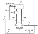
- FIG. 17 is a diagram for explaining a system configuration according to the fifth embodiment.
- the system of this embodiment includes an LPL-EGR mechanism that introduces LPL-EGR (Low Pressure Loop Exhaust Gas Recirculation) gas.
- the LPL-EGR mechanism includes an LPL-EGR pipe 74.
- the LPL-EGR pipe 74 connects the exhaust pipe 14 on the downstream side of the turbine 12 a and the intake pipe 16 on the upstream side of the connection portion between the PCV pipe 20 and the intake pipe 16. Since the configuration other than the LPL-EGR mechanism is the same as that of the first embodiment, description thereof is omitted.
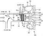
- FIG. 18 is an enlarged cross-sectional view of the vicinity of the compressor 12b of FIG.
- a tubular member 76 is disposed inside the intake pipe 16.
- the tubular member 76 is a straight tubular member similar to the tubular member 34 of FIG. Therefore, the droplet oil 38 can be generated on the outer peripheral wall of the tubular member 76 and can flow to the outer peripheral wall.
- the droplet oils 38j and 38k shown in FIG. 18 schematically show a temporary liquid pool state of the droplet oil 38.
- the downstream end 76 a of the tubular member 76 is disposed so as to face the inlet portion 28. Therefore, blow-by gas flows from the PCV pipe 20 into the intake pipe 16 and flows along the outer peripheral wall of the tubular member 76 (that is, the inner peripheral wall of the intake pipe 16) together with the intake gas flowing through the gap 36, and enters the inlet portion 28. Head to.
- the upstream end 76b of the tubular member 76 is inclined toward the LPL-EGR pipe 74 side. That is, the upstream end opening of the tubular member 76 opens toward the opening of the LPL-EGR pipe 74 to the intake pipe 16. Therefore, most of the LPL-EGR gas flows into the tubular member 76 and travels toward the inlet 28 together with the suction gas.
- FIGS. 19 is a cross-sectional view taken along the line AA ′ of FIG.
- blow-by gas flows through the gap 36, and LPL-EGR gas flows through the inside of the tubular member 76.
- the LPL-EGR gas is a high-temperature gas (about 90 ° C.). Therefore, the temperature of the intake gas (that is, the EGR gas-containing gas) when reaching the discharge side 22b of the impeller 22 is higher than the gas temperature when the normal intake gas (that is, air) reaches the discharge side 22b. .
- the soot-containing oil becomes smaller in particle size and higher in viscosity near the inlet 28, and the surface of the diffuser 32 increases. Deposit with probability.
- gas mixing before the compressor 12b flows can be suppressed.
- FIG. 20 is a diagram showing the temperature distribution inside the compressor 12b when the LPL-EGR gas is introduced in a configuration in which the tubular member 76 is not provided.
- the LPL-EGR gas since the LPL-EGR gas has a high temperature, a local high temperature portion is formed on the surface of the diffuser 32 along the gas flow of the LPL-EGR gas.
- oil mist siot-containing oil
- LPL-EGR gas flows from the inside of the tubular member 76 into the compressor 12b. Therefore, mixing of the soot-containing oil and the local high temperature part can be reduced even inside the compressor 12b. Therefore, according to the intake system structure of FIG. 18, it is possible to exert the cleaning effect by the droplet oil 38 while suppressing the mixing of the soot-containing gas and the LPL-EGR gas.
- tubular member 76 corresponds to the “internal pipe” in the sixth invention.
Landscapes
- Engineering & Computer Science (AREA)
- Mechanical Engineering (AREA)
- General Engineering & Computer Science (AREA)
- Chemical & Material Sciences (AREA)
- Combustion & Propulsion (AREA)
- Lubrication Details And Ventilation Of Internal Combustion Engines (AREA)
- Structures Of Non-Positive Displacement Pumps (AREA)
Abstract
Description
内燃機関の吸気管にオイルを含むブローバイガスを導入するPCV管と、
前記PCV管から前記吸気管に導入されたブローバイガス中のオイルの粒径を拡大させると共に該粒径を拡大されたオイルを前記吸気管の内周壁に沿って流通させる大粒径化オイル流通手段と、
を備えることを特徴とする。
前記大粒径化オイル流通手段は、前記吸気管に導入されたブローバイガスが流れるブローバイガス流路上に配置された湾曲状の外周壁を有する吸気管内部材を備え、
前記PCV管は、鉛直方向上方から前記吸気管に接続され、
前記吸気管への前記PCV管の開口と、前記外周壁とが対向配置されることを特徴とする。
前記吸気管内部材よりも下流側において前記吸気管に接続され、前記吸気管を流れるガスを圧縮するコンプレッサを更に備えることを特徴とする。
前記吸気管に導入されたブローバイガス中のオイルの前記外周壁上における流動性を低下させる流動性低下手段が、前記外周壁に設けられることを特徴とする。
前記流動性低下手段が、前記吸気管の上下流方向に延在し、かつ前記外周壁の周方向に間隔を隔てた複数の手段であることを特徴とする。
前記吸気管への前記PCV管の開口よりも上流側から前記吸気管にEGRガスを導入するEGR管を更に備え、
前記吸気管内部材は、前記吸気管よりも小口径の内部配管であり、
前記内部配管の上流端開口が前記吸気管への前記EGR管の開口に向かって開口していることを特徴とする。
[システム構成の説明]
先ず、図1乃至図11を参照しながら、本発明の実施の形態1について説明する。図1は、実施の形態1のシステム構成を説明するための図である。図1に示すように、本実施形態のシステムは、内燃機関としてのエンジン10を備えている。エンジン10の各気筒には、ピストン、吸気弁、排気弁、燃料インジェクタ等が設けられている。なお、エンジン10の気筒数および気筒配置は特に限定されない。
次に、図2乃至図10を参照しながら、本実施形態の特徴について説明する。先ず、図2を参照しながら、本実施形態の特徴部分に相当する吸気系の構造について説明する。図2は、図1のコンプレッサ12b近傍の断面拡大図である。図2に示すように、コンプレッサ12bは、インペラ22とハウジング24と連結軸26とを備えている。ハウジング24は、インペラ22を回転不能に支持する連結軸26を回転自在に支持するものである。ハウジング24には、インペラ22の吸入側22aに吸気を導く入口部28と、インペラ22の外周に配置される渦巻き状のスクロール30と、インペラ22の吐出側22bとスクロール30とを連通するディフューザ32とが設けられている。連結軸26は、タービン12aのタービンホイール(不図示)に接続されている。
図11は、上記実施の形態1の変形形態を説明するための図である。例えば、管状部材34の代わりに、管状部材34の重力方向下方部を切り欠いた形状の管状部材40を用い、この管状部材40にブローバイガスを衝突させて液滴オイル38を発生させ、その外周壁に沿うように流通させることもできる(図11(A))。また、例えば、PCV管20の吸気管16側出口に設けたガス絞り部材(液化促進部材)41と、管状部材34の鉛直方向下方部を、上記管状部材40の切り欠きよりも大きく切り欠いた管状部材42とを組み合わせて用いることもできる(図11(B))。なお、上記ガス絞り部材41は、より具体的には、切頭円錐管状の部材であって、径が大きい方の端部がPCV管20と吸気管16との接続部位に接続されて径が小さい方の端部が吸気管16の内部に位置している部材である。更に、例えば、PCV管20と吸気管16との接続部位に設けたガス衝突用部材(液化促進部材)43と、管状部材34を略右半分を切り欠いた管状部材44とを組み合わせて用いることもできる(図11(C))。なお、上記ガス衝突用部材43は、PCV管20と吸気管16との接続部位の一部からPCV管20の中心軸線に向かって且つ吸気管16内部に向かって延在する部材であり、上記管状部材44は、上記ガス衝突用部材43の吸気管16の端部からPCV管20の開口の下側を通って吸気管16の内周面に沿って吸気管16の鉛直方向下方領域まで延在する部材である。更にまた、管状部材40よりも管径の小さい管状部材45と、管状部材40の上方部を切り欠いた形状の管状部材46とを組み合わせて用いることもできる(図11(D))。なお、図11に示す液滴オイル38c,38d,38e,38fは、液滴オイル38の一時的な液溜り状態を模式的に示したものである。
また、上記実施の形態1においては、管状部材34および吸気管16は、両者の中心軸が一致するように配置した。しかしながら、これらの中心軸は必ずしも一致していなくてもよい。即ち、図11(B)で示したように、管状部材34の中心軸が吸気管16の中心軸に対して重力方向下方となるように配置してもよい。
このように、ブローバイガス中のオイルの粒径を拡大させつつ吸気管16の内周壁に沿うように流通させることが可能な手段であれば、上記実施の形態1の管状部材34に代用できる。なお、本変形例は後述する各実施形態においても同様に適用が可能である。
また、上記実施の形態1において、管状部材34の中心軸線に対して垂直な断面形状は、円形であるが、当該断面形状は、楕円形や多角形(たとえば、五角形、六角形等)であってもよい。
また、上記実施の形態1やその変形形態においては、管状部材34,40,42,44,45が上記第2の発明における「吸気管内部材」に相当している。
[実施の形態2の特徴]
次に、図12乃至図13を参照しながら、本発明の実施の形態2について説明する。本実施形態においては、上記実施の形態1の管状部材34を、図12に示す管状部材66に置き換えた点をその特徴とする。そのため、以下においてはこの特徴部分を中心に説明し、システム構成その他既に上記実施の形態1で説明した内容については省略する。
[実施の形態3の特徴]
次に、図14を参照しながら、本発明の実施の形態3について説明する。本実施形態においては、上記実施の形態1の管状部材34を、図14に示す管状部材70に置き換えた点をその特徴とする。そのため、以下においてはこの特徴部分を中心に説明し、システム構成その他既に上記実施の形態1で説明した内容については省略する。
[実施の形態4の特徴]
次に、図15を参照しながら、本発明の実施の形態4について説明する。本実施形態においては、上記実施の形態1の管状部材34を、図15に示す管状部材72に置き換えた点をその特徴とする。そのため、以下においてはこの特徴部分を中心に説明し、システム構成その他既に上記実施の形態1で説明した内容については省略する。
次に、図17乃至図20を参照しながら、本発明の実施の形態5について説明する。本実施形態は、図17のシステム構成において、図18の吸気系構造とすることをその特徴とする。
図17は、実施の形態5のシステム構成を説明するための図である。図17に示すように、本実施形態のシステムは、LPL-EGR(Low Pressure Loop Exhaust Gas Recirculation)ガスを導入するLPL-EGR機構を備えている。LPL-EGR機構は、LPL-EGR管74を備えている。LPL-EGR管74は、タービン12aよりも下流側の排気管14と、PCV管20と吸気管16との接続部位よりも上流側の吸気管16とを接続するものである。LPL-EGR機構以外の構成については、上記実施の形態1と同様であるのでその説明を省略する。
次に、図18乃至図20を参照しながら、本実施形態の特徴について説明する。先ず、図18を参照しながら、本実施形態の特徴部分に相当する吸気系構造と、当該吸気系構造におけるブローバイガス等の流れを説明する。図18は、図17のコンプレッサ12b近傍の断面拡大図である。図18に示すように、吸気管16の内部には、管状部材76が配置されている。管状部材76は、図2の管状部材34同様の直管状の管状部材である。そのため、管状部材76の外周壁において液滴オイル38を発生させ、当該外周壁に流すことができる。なお、図18に示す液滴オイル38j,38kは、液滴オイル38の一時的な液溜り状態を模式的に示したものである。
12 過給機
12a タービン
12b コンプレッサ
16,52 吸気管
20,50 PCV管
22,60 インペラ
22a 吸入側
22b 吐出側
32,64 ディフューザ
34,40,42,44,45,66,68,70,76 管状部材
34a,76a 下流端
36 隙間
38,56 液滴オイル
41 ガス絞り部材
43 ガス衝突用部材
66a 管口絞り部
68a 溝部
70a,72a コーティング部
74 LPL-EGR管
76b 上流端
Claims (6)
- 内燃機関の吸気管にオイルを含むブローバイガスを導入するPCV管と、
前記PCV管から前記吸気管に導入されたブローバイガス中のオイルの粒径を拡大させると共に該粒径を拡大されたオイルを前記吸気管の内周壁に沿って流通させる大粒径化オイル流通手段と、
を備えることを特徴とする内燃機関。 - 前記大粒径化オイル流通手段は、前記吸気管に導入されたブローバイガスが流れるブローバイガス流路上に配置された湾曲状の外周壁を有する吸気管内部材を備え、
前記PCV管は、鉛直方向上方から前記吸気管に接続され、
前記吸気管への前記PCV管の開口と、前記外周壁とが対向配置されることを特徴とする請求項1に記載の内燃機関。 - 前記吸気管内部材よりも下流側において前記吸気管に接続され、前記吸気管を流れるガスを圧縮するコンプレッサを更に備えることを特徴とする請求項2に記載の内燃機関。
- 前記吸気管に導入されたブローバイガス中のオイルの前記外周壁上における流動性を低下させる流動性低下手段が、前記外周壁に設けられることを特徴とする請求項2または3に記載の内燃機関。
- 前記流動性低下手段が、前記吸気管の上下流方向に延在し、かつ前記外周壁の周方向に間隔を隔てた複数の手段であることを特徴とする請求項4に記載の内燃機関。
- 前記吸気管への前記PCV管の開口よりも上流側から前記吸気管にEGRガスを導入するEGR管を更に備え、
前記吸気管内部材は、前記吸気管よりも小口径の内部配管であり、
前記内部配管の上流端開口が前記吸気管への前記EGR管の開口に向かって開口していることを特徴とする請求項2乃至5何れか1項に記載の内燃機関。
Priority Applications (5)
| Application Number | Priority Date | Filing Date | Title |
|---|---|---|---|
| PCT/JP2012/061760 WO2013168232A1 (ja) | 2012-05-08 | 2012-05-08 | 内燃機関 |
| US14/399,315 US20150136096A1 (en) | 2012-05-08 | 2012-05-08 | Internal combustion engine |
| EP12876521.1A EP2848781A4 (en) | 2012-05-08 | 2012-05-08 | COMBUSTION ENGINE |
| JP2014514282A JP5979226B2 (ja) | 2012-05-08 | 2012-05-08 | 内燃機関 |
| CN201280072952.3A CN104271904B (zh) | 2012-05-08 | 2012-05-08 | 内燃机 |
Applications Claiming Priority (1)
| Application Number | Priority Date | Filing Date | Title |
|---|---|---|---|
| PCT/JP2012/061760 WO2013168232A1 (ja) | 2012-05-08 | 2012-05-08 | 内燃機関 |
Publications (1)
| Publication Number | Publication Date |
|---|---|
| WO2013168232A1 true WO2013168232A1 (ja) | 2013-11-14 |
Family
ID=49550317
Family Applications (1)
| Application Number | Title | Priority Date | Filing Date |
|---|---|---|---|
| PCT/JP2012/061760 Ceased WO2013168232A1 (ja) | 2012-05-08 | 2012-05-08 | 内燃機関 |
Country Status (5)
| Country | Link |
|---|---|
| US (1) | US20150136096A1 (ja) |
| EP (1) | EP2848781A4 (ja) |
| JP (1) | JP5979226B2 (ja) |
| CN (1) | CN104271904B (ja) |
| WO (1) | WO2013168232A1 (ja) |
Cited By (3)
| Publication number | Priority date | Publication date | Assignee | Title |
|---|---|---|---|---|
| EP2873837A1 (de) * | 2013-11-19 | 2015-05-20 | Rolls-Royce Deutschland Ltd & Co KG | Strahltriebwerk mit einer Einrichtung zum Einsprühen von Öl |
| EP2873838A1 (de) * | 2013-11-19 | 2015-05-20 | Rolls-Royce Deutschland Ltd & Co KG | Strahltriebwerk mit einer Einrichtung zum Einsprühen von Öl in einen Luft-Öl-Volumenstrom |
| JP2017190684A (ja) * | 2016-04-12 | 2017-10-19 | 株式会社豊田自動織機 | ブローバイガス還元装置 |
Families Citing this family (4)
| Publication number | Priority date | Publication date | Assignee | Title |
|---|---|---|---|---|
| US9926891B2 (en) * | 2015-11-18 | 2018-03-27 | General Electric Company | System and method of exhaust gas recirculation |
| US11261767B2 (en) * | 2019-11-12 | 2022-03-01 | Fca Us Llc | Bifurcated air induction system for turbocharged engines |
| US11415141B1 (en) * | 2021-03-03 | 2022-08-16 | GM Global Technology Operations LLC | Centrifugal compressor having positive crankcase ventilation tube extending through compressor housing to avoid high crankcase pressure |
| US12071872B1 (en) | 2023-03-06 | 2024-08-27 | GM Global Technology Operations LLC | Compressor housing PCV for reducing crankcase pressure |
Citations (11)
| Publication number | Priority date | Publication date | Assignee | Title |
|---|---|---|---|---|
| JPH09317569A (ja) * | 1996-05-22 | 1997-12-09 | Nippon Soken Inc | エンジンのガス還流装置 |
| JPH11294271A (ja) * | 1998-04-10 | 1999-10-26 | Honda Motor Co Ltd | エアクリーナ |
| JPH11311116A (ja) * | 1998-04-27 | 1999-11-09 | Denso Corp | ブローバイガス還元構造 |
| JP2004116292A (ja) | 2002-09-24 | 2004-04-15 | Kubota Corp | 過給機付きエンジン |
| JP2005048734A (ja) | 2003-07-31 | 2005-02-24 | Toyota Motor Corp | 内燃機関の吸気導入装置 |
| JP2007332873A (ja) * | 2006-06-15 | 2007-12-27 | Aisan Ind Co Ltd | ブローバイガスのトラップ装置 |
| JP2009264158A (ja) | 2008-04-23 | 2009-11-12 | Toyota Motor Corp | 内燃機関の吸気装置 |
| JP2009281317A (ja) | 2008-05-23 | 2009-12-03 | Toyota Motor Corp | 内燃機関の吸気管構造 |
| JP2009293464A (ja) | 2008-06-04 | 2009-12-17 | Aisan Ind Co Ltd | 過給機付エンジンのブローバイガス還流装置 |
| JP2010084624A (ja) * | 2008-09-30 | 2010-04-15 | Toyota Motor Corp | エンジンのデポジット抑制装置 |
| JP2010106688A (ja) * | 2008-10-28 | 2010-05-13 | Mitsubishi Heavy Ind Ltd | ガスエンジンの潤滑装置 |
Family Cites Families (23)
| Publication number | Priority date | Publication date | Assignee | Title |
|---|---|---|---|---|
| US552979A (en) * | 1896-01-14 | Joseph baker | ||
| CA1249191A (en) * | 1984-07-18 | 1989-01-24 | Yoshikazu Noguchi | Intake manifold for internal combustion engine having exhaust gas recirculation system |
| US4672939A (en) * | 1984-07-18 | 1987-06-16 | Toyota Jidosha Kabushiki Kaisha | Intake manifold for internal combustion engine having exhaust gas recirculation system |
| US4676717A (en) * | 1985-05-22 | 1987-06-30 | Cummins Atlantic, Inc. | Compressor housing having replaceable inlet throat and method for manufacturing compressor housing |
| US4724807A (en) * | 1986-03-24 | 1988-02-16 | Walker Robert A | In-line air-oil separator |
| US5572979A (en) * | 1995-07-05 | 1996-11-12 | Ford Motor Company | Engine air induction system |
| JPH11117722A (ja) * | 1997-10-20 | 1999-04-27 | Honda Motor Co Ltd | ブローバイガス還流装置 |
| JP2001246216A (ja) * | 1999-12-28 | 2001-09-11 | Denso Corp | 気液分離装置 |
| US6739177B2 (en) * | 2001-03-05 | 2004-05-25 | Toyota Jidosha Kabushiki Kaisha | Combustible-gas sensor, diagnostic device for intake-oxygen concentration sensor, and air-fuel ratio control device for internal combustion engines |
| JP4075051B2 (ja) * | 2003-02-06 | 2008-04-16 | 株式会社デンソー | 吸気装置 |
| US7204241B2 (en) * | 2004-08-30 | 2007-04-17 | Honeywell International, Inc. | Compressor stage separation system |
| US7278412B2 (en) * | 2005-03-31 | 2007-10-09 | Caterpillar Inc. | Combustion-gas recirculation system |
| JP4581829B2 (ja) * | 2005-05-10 | 2010-11-17 | トヨタ自動車株式会社 | オイルセパレータ及びブローバイガス還元装置 |
| JP4299346B2 (ja) * | 2007-02-14 | 2009-07-22 | トヨタ自動車株式会社 | 内燃機関の吸気装置 |
| JP2008240521A (ja) * | 2007-03-23 | 2008-10-09 | Honda Motor Co Ltd | 内燃機関の吸気量制御装置 |
| JP2008255960A (ja) * | 2007-04-09 | 2008-10-23 | Toyota Motor Corp | 過給システム |
| US20090090337A1 (en) * | 2007-10-05 | 2009-04-09 | Aisan Kogyo Kabushiki Kaisha | Engine blow-by gas returning apparatus |
| GB0724701D0 (en) * | 2007-12-18 | 2008-01-30 | Cummins Turbo Tech Ltd | Compressor |
| KR101028552B1 (ko) * | 2008-11-18 | 2011-04-11 | 기아자동차주식회사 | 블로우바이 가스 오일 분리장치 |
| US7992551B2 (en) * | 2008-11-26 | 2011-08-09 | Toyota Motor Engineering & Manufacturing North America, Inc. | Oil capturing device having a rotary component |
| US7886727B2 (en) * | 2009-05-26 | 2011-02-15 | Ford Global Technologies, Llc | Variable venturi system and method for engine |
| JP5478399B2 (ja) * | 2009-09-30 | 2014-04-23 | 株式会社クボタ | エンジンのブローバイガス還流装置 |
| DE102011010289A1 (de) * | 2011-02-03 | 2012-08-09 | GM Global Technology Operations LLC (n. d. Gesetzen des Staates Delaware) | Kurbelgehäuse-Entlüftungseinrichtung für ein Kraftfahrzeug |
-
2012
- 2012-05-08 JP JP2014514282A patent/JP5979226B2/ja not_active Expired - Fee Related
- 2012-05-08 CN CN201280072952.3A patent/CN104271904B/zh not_active Expired - Fee Related
- 2012-05-08 EP EP12876521.1A patent/EP2848781A4/en not_active Withdrawn
- 2012-05-08 US US14/399,315 patent/US20150136096A1/en not_active Abandoned
- 2012-05-08 WO PCT/JP2012/061760 patent/WO2013168232A1/ja not_active Ceased
Patent Citations (11)
| Publication number | Priority date | Publication date | Assignee | Title |
|---|---|---|---|---|
| JPH09317569A (ja) * | 1996-05-22 | 1997-12-09 | Nippon Soken Inc | エンジンのガス還流装置 |
| JPH11294271A (ja) * | 1998-04-10 | 1999-10-26 | Honda Motor Co Ltd | エアクリーナ |
| JPH11311116A (ja) * | 1998-04-27 | 1999-11-09 | Denso Corp | ブローバイガス還元構造 |
| JP2004116292A (ja) | 2002-09-24 | 2004-04-15 | Kubota Corp | 過給機付きエンジン |
| JP2005048734A (ja) | 2003-07-31 | 2005-02-24 | Toyota Motor Corp | 内燃機関の吸気導入装置 |
| JP2007332873A (ja) * | 2006-06-15 | 2007-12-27 | Aisan Ind Co Ltd | ブローバイガスのトラップ装置 |
| JP2009264158A (ja) | 2008-04-23 | 2009-11-12 | Toyota Motor Corp | 内燃機関の吸気装置 |
| JP2009281317A (ja) | 2008-05-23 | 2009-12-03 | Toyota Motor Corp | 内燃機関の吸気管構造 |
| JP2009293464A (ja) | 2008-06-04 | 2009-12-17 | Aisan Ind Co Ltd | 過給機付エンジンのブローバイガス還流装置 |
| JP2010084624A (ja) * | 2008-09-30 | 2010-04-15 | Toyota Motor Corp | エンジンのデポジット抑制装置 |
| JP2010106688A (ja) * | 2008-10-28 | 2010-05-13 | Mitsubishi Heavy Ind Ltd | ガスエンジンの潤滑装置 |
Non-Patent Citations (1)
| Title |
|---|
| See also references of EP2848781A4 |
Cited By (5)
| Publication number | Priority date | Publication date | Assignee | Title |
|---|---|---|---|---|
| EP2873837A1 (de) * | 2013-11-19 | 2015-05-20 | Rolls-Royce Deutschland Ltd & Co KG | Strahltriebwerk mit einer Einrichtung zum Einsprühen von Öl |
| EP2873838A1 (de) * | 2013-11-19 | 2015-05-20 | Rolls-Royce Deutschland Ltd & Co KG | Strahltriebwerk mit einer Einrichtung zum Einsprühen von Öl in einen Luft-Öl-Volumenstrom |
| US9677422B2 (en) | 2013-11-19 | 2017-06-13 | Rolls-Royce Deutschland Ltd & Co Kg | Jet engine comprising a device for spraying oil into an air-oil volume flow |
| US9988938B2 (en) | 2013-11-19 | 2018-06-05 | Rolls-Royce Deutschland Ltd & Co Kg | Jet engine comprising a device for spraying oil |
| JP2017190684A (ja) * | 2016-04-12 | 2017-10-19 | 株式会社豊田自動織機 | ブローバイガス還元装置 |
Also Published As
| Publication number | Publication date |
|---|---|
| EP2848781A1 (en) | 2015-03-18 |
| CN104271904A (zh) | 2015-01-07 |
| EP2848781A4 (en) | 2015-04-22 |
| JPWO2013168232A1 (ja) | 2015-12-24 |
| JP5979226B2 (ja) | 2016-08-24 |
| US20150136096A1 (en) | 2015-05-21 |
| CN104271904B (zh) | 2016-11-16 |
Similar Documents
| Publication | Publication Date | Title |
|---|---|---|
| JP5979226B2 (ja) | 内燃機関 | |
| JP5047352B2 (ja) | 排気ターボ過給機のハウジング構造 | |
| CN103534457B (zh) | 内燃机的进气构造 | |
| US20150159596A1 (en) | Blowby gas ventilation system for supercharger-equipped internal combustion engine | |
| CN105275593A (zh) | 涡轮增压器 | |
| KR102452177B1 (ko) | 기액분리장치 | |
| CN205101078U (zh) | 一种油气分离器及曲轴箱通风系统 | |
| WO2013021456A1 (ja) | 過給エンジンのブローバイガス還元装置 | |
| JP2015045317A (ja) | エンジンの吸気系構造 | |
| JP6003476B2 (ja) | ターボチャージャ | |
| CN109469531B (zh) | 一种曲轴箱通风系统油气分离器总成及车辆 | |
| CN105143636B (zh) | 具备窜缸混合气环流装置的内燃机的增压器的冷却装置 | |
| CN104131860B (zh) | 加装涡轮的迷宫式油气分离室 | |
| CN202170823U (zh) | 发动机强制通风系统 | |
| JP5761135B2 (ja) | 過給機付内燃機関 | |
| JP2016027251A (ja) | ターボチャージャ | |
| CN103850754A (zh) | 引擎的吹漏气机构 | |
| US20140190439A1 (en) | Intake apparatus | |
| JP2014088855A (ja) | 内燃機関のブローバイガス還流装置 | |
| JP5321088B2 (ja) | 潤滑油回収装置 | |
| JP5814537B2 (ja) | ブローバイガス還流装置 | |
| CN203978558U (zh) | 一种加装涡轮的迷宫式油气分离室 | |
| JP2016084710A (ja) | ターボチャージャ | |
| CN103958841A (zh) | 内燃机和用于内燃机运行的方法 | |
| JP2017193963A (ja) | ブローバイガス還流装置 |
Legal Events
| Date | Code | Title | Description |
|---|---|---|---|
| 121 | Ep: the epo has been informed by wipo that ep was designated in this application |
Ref document number: 12876521 Country of ref document: EP Kind code of ref document: A1 |
|
| ENP | Entry into the national phase |
Ref document number: 2014514282 Country of ref document: JP Kind code of ref document: A |
|
| WWE | Wipo information: entry into national phase |
Ref document number: 2012876521 Country of ref document: EP |
|
| WWE | Wipo information: entry into national phase |
Ref document number: 14399315 Country of ref document: US |
|
| NENP | Non-entry into the national phase |
Ref country code: DE |