WO2013168349A1 - バッテリの充電率推定装置 - Google Patents
バッテリの充電率推定装置 Download PDFInfo
- Publication number
- WO2013168349A1 WO2013168349A1 PCT/JP2013/002265 JP2013002265W WO2013168349A1 WO 2013168349 A1 WO2013168349 A1 WO 2013168349A1 JP 2013002265 W JP2013002265 W JP 2013002265W WO 2013168349 A1 WO2013168349 A1 WO 2013168349A1
- Authority
- WO
- WIPO (PCT)
- Prior art keywords
- charging rate
- battery
- current
- charge
- open
- Prior art date
- Legal status (The legal status is an assumption and is not a legal conclusion. Google has not performed a legal analysis and makes no representation as to the accuracy of the status listed.)
- Ceased
Links
Images








Classifications
-
- G—PHYSICS
- G01—MEASURING; TESTING
- G01R—MEASURING ELECTRIC VARIABLES; MEASURING MAGNETIC VARIABLES
- G01R31/00—Arrangements for testing electric properties; Arrangements for locating electric faults; Arrangements for electrical testing characterised by what is being tested not provided for elsewhere
- G01R31/36—Arrangements for testing, measuring or monitoring the electrical condition of accumulators or electric batteries, e.g. capacity or state of charge [SoC]
- G01R31/367—Software therefor, e.g. for battery testing using modelling or look-up tables
-
- G—PHYSICS
- G01—MEASURING; TESTING
- G01R—MEASURING ELECTRIC VARIABLES; MEASURING MAGNETIC VARIABLES
- G01R31/00—Arrangements for testing electric properties; Arrangements for locating electric faults; Arrangements for electrical testing characterised by what is being tested not provided for elsewhere
- G01R31/36—Arrangements for testing, measuring or monitoring the electrical condition of accumulators or electric batteries, e.g. capacity or state of charge [SoC]
- G01R31/382—Arrangements for monitoring battery or accumulator variables, e.g. SoC
-
- G—PHYSICS
- G01—MEASURING; TESTING
- G01R—MEASURING ELECTRIC VARIABLES; MEASURING MAGNETIC VARIABLES
- G01R31/00—Arrangements for testing electric properties; Arrangements for locating electric faults; Arrangements for electrical testing characterised by what is being tested not provided for elsewhere
- G01R31/36—Arrangements for testing, measuring or monitoring the electrical condition of accumulators or electric batteries, e.g. capacity or state of charge [SoC]
- G01R31/3644—Constructional arrangements
- G01R31/3648—Constructional arrangements comprising digital calculation means, e.g. for performing an algorithm
-
- G—PHYSICS
- G01—MEASURING; TESTING
- G01R—MEASURING ELECTRIC VARIABLES; MEASURING MAGNETIC VARIABLES
- G01R31/00—Arrangements for testing electric properties; Arrangements for locating electric faults; Arrangements for electrical testing characterised by what is being tested not provided for elsewhere
- G01R31/36—Arrangements for testing, measuring or monitoring the electrical condition of accumulators or electric batteries, e.g. capacity or state of charge [SoC]
- G01R31/382—Arrangements for monitoring battery or accumulator variables, e.g. SoC
- G01R31/3842—Arrangements for monitoring battery or accumulator variables, e.g. SoC combining voltage and current measurements
-
- H—ELECTRICITY
- H01—ELECTRIC ELEMENTS
- H01M—PROCESSES OR MEANS, e.g. BATTERIES, FOR THE DIRECT CONVERSION OF CHEMICAL ENERGY INTO ELECTRICAL ENERGY
- H01M10/00—Secondary cells; Manufacture thereof
- H01M10/42—Methods or arrangements for servicing or maintenance of secondary cells or secondary half-cells
- H01M10/48—Accumulators combined with arrangements for measuring, testing or indicating the condition of cells, e.g. the level or density of the electrolyte
-
- H—ELECTRICITY
- H01—ELECTRIC ELEMENTS
- H01M—PROCESSES OR MEANS, e.g. BATTERIES, FOR THE DIRECT CONVERSION OF CHEMICAL ENERGY INTO ELECTRICAL ENERGY
- H01M2220/00—Batteries for particular applications
- H01M2220/20—Batteries in motive systems, e.g. vehicle, ship, plane
-
- Y—GENERAL TAGGING OF NEW TECHNOLOGICAL DEVELOPMENTS; GENERAL TAGGING OF CROSS-SECTIONAL TECHNOLOGIES SPANNING OVER SEVERAL SECTIONS OF THE IPC; TECHNICAL SUBJECTS COVERED BY FORMER USPC CROSS-REFERENCE ART COLLECTIONS [XRACs] AND DIGESTS
- Y02—TECHNOLOGIES OR APPLICATIONS FOR MITIGATION OR ADAPTATION AGAINST CLIMATE CHANGE
- Y02E—REDUCTION OF GREENHOUSE GAS [GHG] EMISSIONS, RELATED TO ENERGY GENERATION, TRANSMISSION OR DISTRIBUTION
- Y02E60/00—Enabling technologies; Technologies with a potential or indirect contribution to GHG emissions mitigation
- Y02E60/10—Energy storage using batteries
Definitions
- the present invention relates to a battery charging rate estimation device for estimating a charging rate of a battery used for an electric vehicle or the like.
- charging is performed from an electric motor that supplies power to an electric motor that drives these vehicles, an electric motor that causes energy during braking to function as a generator, or a power supply installed on the ground.
- a rechargeable battery (secondary battery) is used to store electrical energy.
- the state of charge (SOC) in order to keep the battery in an optimal state for a long time, it is necessary to constantly monitor the state of the battery, in particular, the state of charge (SOC) to perform battery management.
- SOC state of charge
- a current integration method also referred to as coulomb counting method or sequential state recording method
- the current integration method records all in / out of battery voltage, current, etc. as time series data, and uses these data to integrate current with time to find the amount of charge at the present time, and initially charge the battery. Determine the charging rate using the value and the full charge capacity.
- an input current value and a terminal voltage value of a battery are input, an open-circuit voltage value which is a state quantity of a model is sequentially estimated using a battery equivalent circuit model, and a charging rate is estimated from the open-circuit voltage value.
- the former current integration method is more accurate than the latter open-circuit voltage method of estimating the charge rate using the open-circuit voltage value in estimating the charging rate in a short time
- the fluctuation of the open-circuit voltage relative to the change in the charging rate is small. Therefore, to estimate the fluctuation amount of the charging rate in a short time, the former current integration method It is inferior to.
- the method of trying to improve the estimation precision of a charge rate is conventionally known by correct
- One of such conventional battery charge rate estimation devices is charging of the battery by an open circuit voltage estimated value estimated using an open circuit voltage method using an adaptive digital filter based on the discharge current and terminal voltage of the battery. Calculating the rate of change and calculating the amount of change in the amount of charge in the battery based on the charge rate, and integrating the charge / discharge current of the battery by the time Based on the difference between the change in the amount of electricity calculated by the second electricity amount calculating means for calculating the amount of change in the amount of electricity charged in the battery based on Offset amount estimation means for estimating the offset amount, and the accuracy of the current measurement value is improved by suppressing the measurement value error of the discharge current measuring instrument by correcting the offset amount.
- a manner is that so as to improve the estimation accuracy of the internal state of the battery, such as a charging rate are known (e.g., see Patent Document 1).
- the battery information acquisition step of measuring battery information (current value, voltage value, temperature value), and the corrected current value corrected using the voltage value are integrated.
- the integration correction step to be determined is executed to correct the measurement error of the battery information to improve the accuracy of the charging rate calculation (for example, see Patent Document 2).
- both of the above-described conventional inventions have the following problems. That is, in the former conventional charging rate estimation apparatus, the amount of change in the amount of electricity estimated using the current integration method and the open-circuit voltage method using the adaptive digital filter is compared, and The error value (offset amount of the current measurement value) of the current detection unit is estimated.
- estimated values such as the amount of electricity obtained by these methods have different statistical characteristics, even if the amounts of change in the amounts of electricity obtained by the above methods are compared as they are, the above-mentioned statistical characteristics The errors caused by can not be avoided. Therefore, it is not possible to estimate the measurement value error of the discharge current measuring device with high accuracy.
- there is fluctuation of the current in the battery due to the uncertainty of the chemical reaction inside the battery As a result, there is a problem that the estimation accuracy of the charging rate of the battery also decreases.
- the present invention has been made in view of the above problems, and its object is to estimate the state of charge of a battery with high accuracy despite fluctuations and variations in the characteristics of the charge / discharge current detection unit and fluctuations in the current in the battery.
- An object of the present invention is to provide a battery charging rate estimation device which can be used.
- the device for estimating the state of charge of a battery according to the invention of claim 1 is A charge / discharge current detection unit that detects charge / discharge current of the battery; A terminal voltage detection unit that detects a terminal voltage of the battery; The open circuit voltage of the battery is estimated based on the charge / discharge current detected by the charge / discharge current detection unit and the terminal voltage detected by the terminal voltage detection unit, and based on the open circuit voltage, the open circuit voltage-charge ratio characteristic of the battery is compared to the open circuit method An open voltage method charging rate estimation unit that estimates the charging rate; A current integration method charging ratio estimation unit that obtains a current integration method charging ratio as a state variable, using a current taking into account fluctuation as an input, and using an open-circuit voltage charging ratio as an observation quantity and a charging / discharging current as outputs When, The error correction value for correcting the current integration method charging rate is obtained by comparing the current integration method charging rate obtained by the current integration method charging rate estimation unit with the open circuit voltage method charging rate estimated by the open
- the battery charging rate estimation device is In the battery charging rate estimation device according to claim 1,
- the error correction value calculation unit has a Kalman filter and obtains an error correction value by multiplying the difference between the current integration method charging rate and the open-circuit voltage charging rate by the Kalman gain. It is characterized by
- the charging rate of the battery can be estimated with high accuracy regardless of fluctuation or variation of the characteristics of the charge / discharge current detection unit or fluctuation of the current in the battery.
- the current integration method charge rate can be easily corrected.
- FIG. 7 is a diagram showing a table in which values of resistors and capacitors in the battery equivalent circuit model of FIG. 2 are summarized in the simulation of the battery charging rate estimating device of the embodiment.
- FIG. 5 is a diagram showing an open circuit voltage-charge ratio characteristic of the battery equivalent circuit model of FIG. 2; It is a figure which shows the waveform of the charging / discharging electric current used by simulation, a terminal voltage, and the waveform of the true value of a charge rate.
- FIG. 6 is a diagram showing a charging rate estimated by a current integration method in a simulation under condition 1; It is a figure which shows the charge rate estimated by the open circuit voltage method in simulation in condition 1.
- FIG. It is a figure which shows the charge rate estimated by the sensor fusion method in simulation in condition 1.
- FIG. It is a figure which shows the error at the time of estimating by a current integration method in simulation on condition 1.
- FIG. It is a figure which shows the error at the time of estimating by the open circuit voltage method in simulation in condition 1.
- FIG. It is a figure which shows the error at the time of estimating by the sensor fusion method in simulation in condition 1.
- FIG. 10 is a diagram showing a charging rate estimated by a current integration method in a simulation under condition 2.
- FIG. 16 is a diagram showing a charging rate estimated by a current integration method in a simulation under condition 6.
- FIG. 16 is a diagram showing a charging rate estimated by the open circuit voltage method in the simulation under the condition 6.
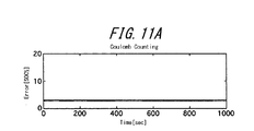
- FIG. 16 is a diagram showing an error when estimated by a current integration method in a simulation under condition 6. It is a figure which shows the error at the time of estimating by the open circuit voltage method in simulation in condition 6. FIG. It is a figure which shows the error at the time of estimating by the sensor fusion method in simulation in condition 6. FIG. It is a figure which compares and shows a simulation result by each estimation method.
- the battery charging rate estimation device of the present embodiment is mounted on a hybrid electric vehicle (HEV: Hybrid Electric Vehicle) equipped with an internal combustion engine and a driving electric motor. Then, the charging rate estimation device is connected to a battery that supplies electric power for operating the driving electric motor or the electric device to the battery, and estimates the charging rate of the battery.
- HEV Hybrid Electric Vehicle
- the charging rate estimation device connected to battery B includes charge / discharge current detection unit 1, terminal voltage detection unit 2, current integration method charging rate estimation unit (current integration method SOC estimation unit) 3 , An open-circuit voltage charging rate estimation unit (open-circuit voltage SOC estimation unit) 4, a subtraction unit 5, and a Kalman filter (Kalman gain) 6.
- Battery B is a rechargeable battery, and in the present embodiment, a lithium ion battery, for example, is used. It is needless to say that the present embodiment is not limited to the battery B being a lithium ion battery, and other types of batteries such as a nickel hydrogen battery may be used.
- the charge / discharge current detection unit 1 detects the magnitude of the discharge current i when the battery B supplies power to an electric motor (not shown) or the like. In addition, charge / discharge current detection unit 1 causes the electric motor to function as a generator at the time of braking, and battery B recovers a part of braking energy, or charging current when battery B charges from a power supply facility on the ground. Detect the size of i.
- Charge / discharge current detection unit 1 detects charge / discharge current i flowing to battery B using, for example, a shunt resistor or the like. The detected charge / discharge current i is input as an input signal to both the current integration method charging rate estimation unit 3 and the open voltage method charging rate estimation unit 4.
- the charge / discharge current detection unit 1 can appropriately adopt one having various structures and types.
- the terminal voltage detection unit 2 detects the voltage between the terminals of the battery B, and the terminal voltage v detected here is input to the open circuit voltage method charging rate estimation unit 4.
- the terminal voltage detection part 2 can employ
- the charge / discharge current i detected by the charge / discharge current detection unit 1 and the error correction value obtained by the Kalman filter 6 are input to the current integration method charging rate estimation unit 3.
- the current integration method charging rate estimation unit 3 receives the current in consideration of fluctuation in the current integration model, obtains the current integration method charging rate as a state variable, and corrects the current integration method charging rate based on the error correction value. Then, this corrected current integration method charging rate SOC i is obtained.
- the current integration method charging rate SOC i is a value obtained by superimposing the error n i on the true charging rate SOC true .
- the current integration method charging rate SOC i is input to the subtracting unit 5. The details of the above-described processing operation in the current integration method charging rate estimation unit 3 will be described later.
- the open-voltage method charging rate estimation unit 4 is based on the charge / discharge current i obtained from the charge / discharge current detection unit 1 and the terminal voltage v obtained from the terminal voltage detection unit 2 as shown in FIG.
- the open circuit voltage OCV (Open Circuit Voltage) of the battery B is estimated by a Kalman filter (not shown) using an equivalent circuit model.
- the open circuit voltage method charging rate estimation unit 4 stores the relationship data of the open circuit voltage [V] -charging rate [%] of the battery B shown in FIG. from the open circuit voltage OCV, obtaining the corresponding open circuit voltage method charging rate SOC v.
- the open voltage method charging rate SOC v is a real charging rate SOC true noise n v of the battery B is superimposed values.
- the open voltage method charging rate SOC v is input to the subtracting unit 5.
- the same input charge / discharge current, battery temperature, etc.
- the Kalman filter compares the outputs (terminal voltages) of the battery equivalent circuit model and the actual battery B. If there is a difference between the two, the Kalman filter multiplies this difference by Kalman gain and feeds it back, and corrects the values of the resistors and capacitors that make up the battery equivalent circuit model so as to minimize the error. This is repeated sequentially to estimate an open circuit voltage OCV or the like which is a true internal state quantity.
- the battery equivalent circuit model shown in FIG. 2 uses a Foster-type RC ladder circuit in this embodiment.
- This circuit the resistor r 0 to set the DC component of the ohmic resistance and the like by the electrolytic solution resistance and wiring of the battery B, and consisting of a fast charge representing the response transfer resistance r 1, r 2 and a capacitor c 1, c 2 Prefecture
- four parallel circuits each composed of parallel circuits each consisting of diffusion process resistances r 3 and r 4 representing slow response and capacitors c 3 and c 4 .
- the subtraction unit 5 subtracts the current integration method charging rate SOC i obtained by the current integration method charging rate estimation unit 3 from the open voltage method charging rate SOC v obtained by the open voltage method charging rate estimation unit 4 to obtain an error difference ( Get n v -n i ). The difference of this error is input to the Kalman filter 6.
- the Kalman filter 6 calculates the error correction value by multiplying the difference (n v ⁇ n i ) of the error input from the subtraction unit 5 by the Kalman gain. Then, the Kalman filter 6 inputs this error correction value to the current integration method charging rate estimation unit 3. Note that the Kalman filter 6, an error n i of the current integration method charging rate SOC i fed back to adjust the Kalman gain so that the zero. Also, the subtraction unit 5 and the Kalman filter 6 correspond to the error correction value calculation unit of the present invention.
- SOC is a charge rate
- i is a charge / discharge current
- FCC is a full charge capacity
- ⁇ t is a sampling cycle.
- the subscript k represents the time of discrete time.
- the state variable x, the input u and the output y are respectively defined as follows.
- the output is set to two, the charge rate SOC and the charge / discharge current i. That is, two of the charge rate SOC estimated by the open-circuit voltage method and the charge / discharge current i detected by the charge / discharge current detection unit 1 are considered as observation quantities, and sensor noise of normal whiteness is placed on them respectively It shall be.
- the discrete-time state-space model is ⁇ ⁇ ⁇ ⁇ for process noise and w for sensor noise It is expressed as
- the state variable x is the charging rate
- the input u is the charging / discharging current.
- the current flowing outside the battery and the current flowing inside the battery are not necessarily equal.
- a complicated electrochemical reaction is performed, and a local current bias exists inside the battery, and it is considered that charges are apparently generated or dissipated.
- the current flowing inside the battery is considered to be one of the state variables of the battery, and the process noise of normal whiteness (average value 0) is carried there be able to.
- equation (8) can be used rather than assuming that process noise does not affect the system with current as the equation (5). Assuming that process noise exists, as in), is considered to be a reality. In an actual design, the process noise of this current is determined as a tuning parameter in a trial and error manner.
- the result of having performed simulation is shown about the effectiveness of the charge rate estimation apparatus of the said Example.
- the battery model simulating the HEV battery has the value shown in FIG. 3 in the equivalent circuit model of FIG. 2 and has the open circuit voltage-charge ratio characteristic shown in FIG.
- the waveforms of the charging / discharging current and terminal voltage at this time and the true values of the charging rate are shown in FIG.
- the horizontal axis shows time [sec]
- the upper stage shows the charge / discharge current [A]
- the middle stage shows the terminal voltage [V]
- the lower stage shows the true value of the charging rate [%].
- This waveform is a waveform in the case where the HEV travels in heavy traffic mainly in urban areas and frequently accelerates / decelerates.
- the HEV is characterized in that the charging rate is controlled to around 50% by the power generation by the internal combustion engine in addition to the charging by the regenerative brake, and this point is an EV that is not charged except during the traveling. And a big difference.
- processing conforming to the actual HEV / EV sensor such as quantization error and sensor noise is added to the current / terminal voltage waveform.
- the current sensor applies noise as an average value of 0 A and a dispersion of 0.5 A, and quantizes with a quantization width of 0.7 A.
- the voltage sensor applies noise with an average value of 0 V and a dispersion of 20 mV, and quantizes with a quantization width of 20 mV.
- the sampling cycle was 0.1 second.
- dispersion Q of process noise of Kalman filter dispersion r of sensor noise
- initial value of estimated value of state variable initial value of estimated value of state variable
- covariance P 0 covariance
- SOC initial is an initial value of the measured charging rate. Therefore, for example, in conditions 4 to 7, a value to which an error is added is given as an initial value.
- the simulation results will be described below by comparing the results of the estimation methods.
- the charging rate estimation results of the simulation under the condition 1 are shown in FIGS. 6A to 6C, and the absolute values of the errors at that time are shown in FIGS. 7A to 7C.
- the horizontal axis represents time [sec]
- the vertical axis in FIG. 6A represents the charging rate estimated by the current integration method [%]
- the vertical axis in FIG. 6B represents the open voltage method using a Kalman filter.
- the charging rate [%] and the vertical axis in FIG. 6C indicate the charging rate estimated by the sensor fusion method.
- solid and broken lines indicate estimated and true values, respectively. Note that, in FIG.
- the broken line overlaps and hides the solid line in portions where the values indicated by the solid line and the broken line are the same or very close to each other.
- the horizontal axis represents time [sec]
- the vertical axis in FIG. 7A represents the error in the charging rate estimated by the current integration method [%]
- the vertical axis in FIG. 7B represents the open voltage method using a Kalman filter.
- the error [%] of the charging rate estimated by the above equation and the vertical axis of FIG. 7C indicate the error [%] of the charging rate estimated by the sensor fusion method. In this case, in the sensor fusion method, it can be seen that the estimated charging rate converges to almost a true value.
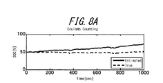
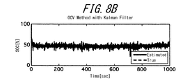
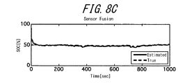
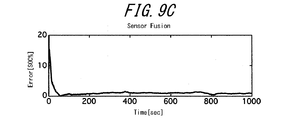
- FIGS. 8A to 8C The charging rate estimation results of the simulation of condition 2 are shown in FIGS. 8A to 8C, and the absolute values of the errors at that time are shown in FIGS. 9A to 9C.
- time is plotted on the horizontal axis and the charging rate and error by each estimation method are represented on the vertical axis.
- the charge rate diverges, and in the open-circuit voltage method, the charge rate remains near the true value with noise, but in the sensor fusion method It can be seen that the charging rate can be estimated with high accuracy by fusing.
- FIGS. 10A to 10C The charging rate estimation results of the simulation of the condition 6 are shown in FIGS. 10A to 10C, and the absolute values of the errors at that time are shown in FIGS. 11A to 11C.
- time is plotted on the horizontal axis, and the charging rate and error by each estimation method are represented on the vertical axis.
- the estimation accuracy is not so good as compared with the case of the conditions 1 and 2 described above. That is, an offset error occurs in the current integration method. This is because the voltage sensor is used to obtain the initial value, and the offset error of the voltage sensor affects it.
- the estimated charging rate contains much noise.
- an offset error similar to that of the current integration method occurs even after convergence.
- the estimation accuracy is deteriorated, there is no problem in practical use.
- the cause of the above estimation error deterioration under the condition 6 is the open circuit voltage method.
- the effect of the offset error of the voltage sensor is that it appears in the form of the offset error of the charge ratio estimation in the open-circuit voltage method, and no correction is made even in combination with the current integration method in which the offset error occurs. become.
- the open circuit voltage method had an estimated value including noise but no offset error, so that it could be corrected by the sensor fusion method.
- the device for estimating the charging rate of a battery according to the present invention can be applied not only to hybrid electric vehicles but also to devices that estimate the charging rate using an electric vehicle and other batteries.
Landscapes
- Physics & Mathematics (AREA)
- General Physics & Mathematics (AREA)
- Engineering & Computer Science (AREA)
- Manufacturing & Machinery (AREA)
- Chemical & Material Sciences (AREA)
- Chemical Kinetics & Catalysis (AREA)
- Electrochemistry (AREA)
- General Chemical & Material Sciences (AREA)
- Secondary Cells (AREA)
- Tests Of Electric Status Of Batteries (AREA)
- Charge And Discharge Circuits For Batteries Or The Like (AREA)
Description
本発明は、電気自動車等に用いるバッテリの充電率を推定するバッテリの充電率推定装置に関する。
たとえば、電気自動車やハイブリッド電気自動車などでは、これらの車両を駆動する電気モータへ電力を供給したり、制動時のエネルギを発電機として機能させる電気モータから、あるいは地上に設置した電源から、充電して電気エネルギを蓄積したりするため、リチャージャブル・バッテリ(二次電池)が用いられる。
この場合、長期にわたってバッテリを最適な状態に保つためには、バッテリの状態、とりわけ充電率(SOC: State of Charge)を常にモニタして、バッテリ・マネージメントを行う必要がある。
従来の充電率検出方法としては、電流積算法(クーロン・カウント法あるいは逐次状態記録法ともいう)及び開放電圧法が知られている。電流積算法は、バッテリの電圧や電流などの出入りを時系列データですべて記録し、これらのデータを用いて電流を時間積分して現時点での電荷量を求め、バッテリに充電された電荷の初期値と満充電容量を用いて充電率を求める。開放電圧法は、バッテリの入力電流値と端子電圧値が入力され、バッテリ等価回路モデルを用いてモデルの状態量である開放電圧値を逐次推定し、この開放電圧値から充電率を推定する。
従来の充電率検出方法としては、電流積算法(クーロン・カウント法あるいは逐次状態記録法ともいう)及び開放電圧法が知られている。電流積算法は、バッテリの電圧や電流などの出入りを時系列データですべて記録し、これらのデータを用いて電流を時間積分して現時点での電荷量を求め、バッテリに充電された電荷の初期値と満充電容量を用いて充電率を求める。開放電圧法は、バッテリの入力電流値と端子電圧値が入力され、バッテリ等価回路モデルを用いてモデルの状態量である開放電圧値を逐次推定し、この開放電圧値から充電率を推定する。
上記各方法には一長一短があり、前者の電流積算法は、短時間での充電率の推定にあっては、開放電圧値を用いて充電率を推定する後者の開放電圧法より精度が高いものの、常時観測が必要である上、時間が経つにつれ誤差が集積されて精度が悪くなっていく。これに対し、後者の開放電圧法では、常時観測は必要ないものの、充電率の変化に対する開放電圧の変動が小さいため、短時間における充電率の変動量を推定するには、前者の電流積算法に劣っている。
そこで、これらの方法で得られた充電率の推定誤差を補正していくことで、充電率の推定精度を向上させようとする方法が従来から知られている。
そこで、これらの方法で得られた充電率の推定誤差を補正していくことで、充電率の推定精度を向上させようとする方法が従来から知られている。
このような従来のバッテリの充電率推定装置の一つとしては、バッテリの放電電流と端子電圧を基に適応デジタル・フィルタを用いた開放電圧法を用いて推定した開放電圧推定値によりバッテリの充電率を算出し、この充電率に基づいてバッテリに充電されている電気量の変化量を算出する第1電気量算出手段と、電流積算法でバッテリの充放電電流を時間積算してこの積算値に基づいてバッテリに充電されている電気量の変化量を算出する第2電気量算出手段と、これら両算出手段でそれぞれ求めた電気量の変化の差分から放電電流計測器の計測値誤差であるオフセット量を推定するオフセット量推定手段と、を備え、オフセット量分を補正することにより放電電流計測器の計測値誤差を小さく抑えることで電流計測値の精度を上げるようにして、充電率等のバッテリの内部状態の推定精度を向上させるようにしたものが知られている(例えば、特許文献1参照)。
また、従来の他のバッテリの充電率推定方法としては、バッテリ情報(電流値、電圧値、温度値)を測定するバッテリ情報取得段階と、電圧値を用いて補正した補正電流値を積算して電流積算値を算出する電流補正段階と、補正電流値を積算して電流積算値を算出し、さらに電流積算値とバッテリ充放電効率が反映された電流積算容量を算出する積算容量算出段階と、バッテリ情報から算出したバッテリの順電圧容量に基づき、電流積算容量の補正の可否を判定する補正可否判定段階と、この判定結果に応じて電流積算容量を補正あるいは補正せずにバッテリの残存容量を求める積算補正段階と、を実行して、バッテリ情報の測定誤差を補正して充電率算出の精度を向上させるようにしたものが知られている(例えば、特許文献2参照)。
しかしながら、上記両従来発明にあっては、以下の問題点をそれぞれ有している。
すなわち、上記前者の従来の充電率推定装置にあっては、電流積算法と適応デジタル・フィルタを用いた開放電圧法とを用いてそれぞれ推定した電気量の変化量を比較し、これらの差分から電流検出部の誤差値(電流計測値のオフセット量)を推定している。
しかしながら、これらの方法で求めた電気量などの推定値はそれぞれ異なった統計的特徴を有しているので、上記方法で得た電気量の変化量をそのまま比較し合っても、上記統計的特徴に起因した誤差を避けることはできない。そのため、高精度で放電電流計測器の計測値誤差を推定することはできない。また、バッテリ内部の化学反応の不確かさによるバッテリ内の電流の揺らぎがある。その結果、バッテリの充電率の推定精度も低下してしまうといった問題がある。
すなわち、上記前者の従来の充電率推定装置にあっては、電流積算法と適応デジタル・フィルタを用いた開放電圧法とを用いてそれぞれ推定した電気量の変化量を比較し、これらの差分から電流検出部の誤差値(電流計測値のオフセット量)を推定している。
しかしながら、これらの方法で求めた電気量などの推定値はそれぞれ異なった統計的特徴を有しているので、上記方法で得た電気量の変化量をそのまま比較し合っても、上記統計的特徴に起因した誤差を避けることはできない。そのため、高精度で放電電流計測器の計測値誤差を推定することはできない。また、バッテリ内部の化学反応の不確かさによるバッテリ内の電流の揺らぎがある。その結果、バッテリの充電率の推定精度も低下してしまうといった問題がある。
また、上記後者の従来の充電率推定方法にあっては、放電電流計測器の特性が使用時間・使用状況・使用環境などによって変化していく上、計測器自体の個体差によるばらつきを避けることができない。それにもかかわらず、この従来方法にあっては、すべての放電電流計測器が同じ特性を有するものと仮定して上記推定を行っているので、実際の特性との相違に起因した計測値の誤差には対応できない。そのため、高い精度で放電電流計測器の計測値誤差を推定することはできない。また、バッテリ内部の化学反応の不確かさによるバッテリ内の電流の揺らぎがある。その結果、この方法でもバッテリの充電率を高精度に推定することは難しいといった問題がある。
本発明は、上記不具合に鑑みなされたもので、その目的は充放電電流検出部の特性の変動やばらつき、またバッテリ内の電流の揺らぎにもかかわらず、高精度でバッテリの充電率の推定ができるようにしたバッテリの充電率推定装置を提供することにある。
この目的のため、請求項1の本発明によるバッテリの充電率推定装置は、
バッテリの充放電電流を検出する充放電電流検出部と、
バッテリの端子電圧を検出する端子電圧検出部と、
充放電電流検出部で検出した充放電電流および端子電圧検出部で検出した端子電圧に基づいてバッテリの開放電圧を推定し、この開放電圧を基にバッテリの開放電圧-充電率特性から開放電圧法充電率を推定する開放電圧法充電率推定部と、
電流積算モデルにて、揺らぎを考慮した電流を入力とし、観測量としての開放電圧法充電率および充放電電流を出力として、状態変数としての電流積算法充電率を求める電流積算法充電率推定部と、
電流積算法充電率推定部で得た電流積算法充電率と開放電圧法充電率推定部で推定した開放電圧法充電率とを比較することにより、電流積算法充電率を修正する誤差修正値を算出する誤差修正値算出部と、
を備え、
電流積算法充電率推定部が、電流積算法充電率を、誤差修正値算出部で算出した誤差修正値によって修正するようにした、
充電率推定装置である。
バッテリの充放電電流を検出する充放電電流検出部と、
バッテリの端子電圧を検出する端子電圧検出部と、
充放電電流検出部で検出した充放電電流および端子電圧検出部で検出した端子電圧に基づいてバッテリの開放電圧を推定し、この開放電圧を基にバッテリの開放電圧-充電率特性から開放電圧法充電率を推定する開放電圧法充電率推定部と、
電流積算モデルにて、揺らぎを考慮した電流を入力とし、観測量としての開放電圧法充電率および充放電電流を出力として、状態変数としての電流積算法充電率を求める電流積算法充電率推定部と、
電流積算法充電率推定部で得た電流積算法充電率と開放電圧法充電率推定部で推定した開放電圧法充電率とを比較することにより、電流積算法充電率を修正する誤差修正値を算出する誤差修正値算出部と、
を備え、
電流積算法充電率推定部が、電流積算法充電率を、誤差修正値算出部で算出した誤差修正値によって修正するようにした、
充電率推定装置である。
請求項2によるバッテリの充電率推定装置は、
請求項1のバッテリの充電率推定装置において、
誤差修正値算出部が、カルマン・フィルタを有して、電流積算法充電率と開放電圧法充電率との差にカルマン・ゲインを掛けて誤差修正値を得る、
ことを特徴とする。
請求項1のバッテリの充電率推定装置において、
誤差修正値算出部が、カルマン・フィルタを有して、電流積算法充電率と開放電圧法充電率との差にカルマン・ゲインを掛けて誤差修正値を得る、
ことを特徴とする。
請求項1のバッテリの充電率推定装置にあっては、充放電電流検出部の特性の変動やばらつき、またバッテリ内の電流の揺らぎにもかかわらず、バッテリの充電率を高精度で推定できる。
請求項2のバッテリの充電率推定装置にあっては、カルマン・フィルタを用いることで、簡単に電流積算法充電率を修正することができる。
以下、本発明の実施の形態を、図面に示す一実施例に基づき詳細に説明する。
本実施例のバッテリの充電率推定装置は、内燃エンジンと駆動用の電気モータを備えたハイブリッド自動車(HEV: Hybrid Electric Vehicle)に搭載されている。そして、充電率推定装置は、駆動用の電気モータや電気装置を稼働するための電力をこれらに供給するバッテリに接続されて、このバッテリの充電率を推定するものである。
まず、本実施例のバッテリの充電率推定装置の全体構成を図1に基づいて説明する。
同図に示すように、バッテリBに接続された充電率推定装置は、充放電電流検出部1と、端子電圧検出部2と、電流積算法充電率推定部(電流積算法SOC推定部)3と、開放電圧法充電率推定部(開放電圧法SOC推定部)4と、減算部5と、カルマン・フィルタ(カルマン・ゲイン)6と、を有する。
同図に示すように、バッテリBに接続された充電率推定装置は、充放電電流検出部1と、端子電圧検出部2と、電流積算法充電率推定部(電流積算法SOC推定部)3と、開放電圧法充電率推定部(開放電圧法SOC推定部)4と、減算部5と、カルマン・フィルタ(カルマン・ゲイン)6と、を有する。
バッテリBは、リチャージャブル・バッテリであり、本実施例にあっては、たとえばリチウム・イオン・バッテリを用いる。なお、本実施例は、バッテリBがリチウム・イオン・バッテリであることに限られることはなく、ニッケル・水素バッテリ等、他の種類のバッテリを用いてもよいことは言うまでもない。
充放電電流検出部1は、バッテリBから図示しない電気モータ等へ電力を供給する場合の放電電流iの大きさを検出する。また、充放電電流検出部1は、制動時に電気モータを発電機として機能させて制動エネルギの一部をバッテリBが回収したり、地上の電源設備からバッテリBが充電したりする場合の充電電流iの大きさを検出する。充放電電流検出部1は、たとえば、シャント抵抗等を使ってバッテリBに流れる充放電電流iを検出する。
検出した充放電電流iは、入力信号として電流積算法充電率推定部3と開放電圧法充電率推定部4との双方に入力される。
なお、充放電電流検出部1は、種々の構造・形式を有するものを適宜採用できる。
検出した充放電電流iは、入力信号として電流積算法充電率推定部3と開放電圧法充電率推定部4との双方に入力される。
なお、充放電電流検出部1は、種々の構造・形式を有するものを適宜採用できる。
端子電圧検出部2は、バッテリBの端子間の電圧を検出するものであり、ここで検出した端子電圧vは開放電圧法充電率推定部4に入力される。
なお、端子電圧検出部2は、種々の構造・形式を有するものを適宜採用できる。
なお、端子電圧検出部2は、種々の構造・形式を有するものを適宜採用できる。
電流積算法充電率推定部3には、充放電電流検出部1で検出された充放電電流iとカルマン・フィルタ6で得られた誤差修正値とが入力される。電流積算法充電率推定部3は、電流積算モデルにて揺らぎを考慮した電流を入力として、状態変数としての電流積算法充電率を求めるとともに、誤差修正値に基づいて電流積算法充電率を修正して、この修正した電流積算法充電率SOCiを得る。
ここで、電流積算法充電率SOCiは、真の充電率SOCtrueに誤差niが重畳された値になっている。
この電流積算法充電率SOCiは、減算部5に入力される。
なお、電流積算法充電率推定部3での上記処理演算の詳細は後で説明する。
ここで、電流積算法充電率SOCiは、真の充電率SOCtrueに誤差niが重畳された値になっている。
この電流積算法充電率SOCiは、減算部5に入力される。
なお、電流積算法充電率推定部3での上記処理演算の詳細は後で説明する。
開放電圧法充電率推定部4は、充放電電流検出部1から得られた充放電電流iと、端子電圧検出部2から得られた端子電圧vとに基づき、バッテリBの図2に示すバッテリ等価回路モデルを用いて図示しないカルマン・フィルタでバッテリBの開放電圧OCV(Open Circuit Voltage)を推定する。
開放電圧法充電率推定部4は、あらかじめ実験で求めた図4に示すバッテリBの開放電圧[V]-充電率[%]の関係データを記憶してあり、この関係データを用いて上記推定した開放電圧OCVから、対応する開放電圧法充電率SOCvを求める。なお、この開放電圧法充電率SOCvは、バッテリBの真の充電率SOCtrueにノイズnvが重畳された値となっている。
この開放電圧法充電率SOCvは、減算部5に入力される。
開放電圧法充電率推定部4は、あらかじめ実験で求めた図4に示すバッテリBの開放電圧[V]-充電率[%]の関係データを記憶してあり、この関係データを用いて上記推定した開放電圧OCVから、対応する開放電圧法充電率SOCvを求める。なお、この開放電圧法充電率SOCvは、バッテリBの真の充電率SOCtrueにノイズnvが重畳された値となっている。
この開放電圧法充電率SOCvは、減算部5に入力される。
開放電圧法充電率推定部4のカルマン・フィルタでは、バッテリBのバッテリ等価回路モデルに、実際のバッテリBと同じ入力(充放電電流やバッテリ温度など)が入力される。そして、カルマン・フィルタは、バッテリ等価回路モデルと実際のバッテリBとの出力(端子電圧)を比較する。両者に差があれば、カルマン・フィルタは、この差にカルマン・ゲインを掛けてフィードバックし、誤差が最小になるようにバッテリ等価回路モデルを構成する抵抗やコンデンサの値を修正していく。これを逐次繰り返して、真の内部状態量である開放電圧OCVなどを推定する。
一方、図2に示すバッテリ等価回路モデルは、本実施例では、フォスタ型RC梯子回路を用いる。
この回路は、バッテリBの電解液抵抗と結線によるオーム抵抗等の直流成分を設定する抵抗r0に、速い応答を表す電荷移動抵抗r1、r2とコンデンサc1、c2とからなるそれぞれの並列回路、および遅い応答を表す拡散過程抵抗r3、r4とコンデンサc3、c4とからなるそれぞれの並列回路で構成された4つの並列回路を直列接続したものである。
図2に示しているように、上記回路にあっては、各並列回路はそれぞれ電圧e1、e2、e3、e4を有し、端子電圧vは、開放電圧OCVに過電圧η(=r0×i+e1+e2+e3+e4)を加算した値となる。
この回路は、バッテリBの電解液抵抗と結線によるオーム抵抗等の直流成分を設定する抵抗r0に、速い応答を表す電荷移動抵抗r1、r2とコンデンサc1、c2とからなるそれぞれの並列回路、および遅い応答を表す拡散過程抵抗r3、r4とコンデンサc3、c4とからなるそれぞれの並列回路で構成された4つの並列回路を直列接続したものである。
図2に示しているように、上記回路にあっては、各並列回路はそれぞれ電圧e1、e2、e3、e4を有し、端子電圧vは、開放電圧OCVに過電圧η(=r0×i+e1+e2+e3+e4)を加算した値となる。
減算部5は、開放電圧法充電率推定部4で得た開放電圧法充電率SOCvから電流積算法充電率推定部3で得た電流積算法充電率SOCiを減算して誤差の差分(nv-ni)を得る。
この誤差の差分は、カルマン・フィルタ6に入力される。
この誤差の差分は、カルマン・フィルタ6に入力される。
カルマン・フィルタ6は、減算部5から入力された誤差の差分(nv-ni)にカルマン・ゲインを掛けてこの誤差修正値を算出する。そして、カルマン・フィルタ6は、この誤差修正値を電流積算法充電率推定部3に入力する。
なお、このカルマン・フィルタ6は、電流積算法充電率SOCiの誤差niがゼロとなるようにカルマン・ゲインを調整してフィードバックする。
また、減算部5とカルマン・フィルタ6とは、本発明の誤差修正値算出部に相当する。
なお、このカルマン・フィルタ6は、電流積算法充電率SOCiの誤差niがゼロとなるようにカルマン・ゲインを調整してフィードバックする。
また、減算部5とカルマン・フィルタ6とは、本発明の誤差修正値算出部に相当する。
次に、電流積算法充電率推定部3で実行される処理について、以下に説明する。
ここでは、開放電圧法で推定した充電率SOCvを使って電流積算法の計算に修正を加えることで全体をシンプルな構成にすることが可能となる。そのためのカルマン・フィルタ・モデルを考える。
ここでは、開放電圧法で推定した充電率SOCvを使って電流積算法の計算に修正を加えることで全体をシンプルな構成にすることが可能となる。そのためのカルマン・フィルタ・モデルを考える。
まず、式(1)のような電流積算モデルを考える。

ここで、SOCは充電率、iは充放電電流、FCCは満充電容量、Δtはサンプリング周期である。また、添え字kは、離散時間の時刻を表す。
上記式(1)において、状態変数x、入力u、出力yを、それぞれ以下のように定義する。

上記式において、特に、出力を充電率SOCと充放電電流iとの2つにしている。
すなわち、開放電圧法で推定した充電率SOCと、充放電電流検出部1で検出した充放電電流iとの2つを観測量として考え、それらにそれぞれ正規白色性のセンサ・ノイズが乗っているものとする。
すなわち、開放電圧法で推定した充電率SOCと、充放電電流検出部1で検出した充放電電流iとの2つを観測量として考え、それらにそれぞれ正規白色性のセンサ・ノイズが乗っているものとする。
このとき、離散時間状態空間モデルは、プロセス・ノイズをν、センサ・ノイズをwとして、

と表される。なお、ここで、状態変数xは充電率、また入力uは充放電電流である。
と表される。なお、ここで、状態変数xは充電率、また入力uは充放電電流である。
次に、電流に関するプロセス・ノイズを考えるために、このモデルを拡大系に書き換える。
すなわち、拡大系の状態変数zを、

とすると、拡大系の離散時間状態空間モデルは、

となる。
ただし、ζは電流に関するプロセス・ノイズ、すなわち電流の揺らぎである。
この電流の揺らぎを追加したモデルに対してカルマン・フィルタを適用することで、より良い充電率を推定することが可能とする。
すなわち、拡大系の状態変数zを、
ただし、ζは電流に関するプロセス・ノイズ、すなわち電流の揺らぎである。
この電流の揺らぎを追加したモデルに対してカルマン・フィルタを適用することで、より良い充電率を推定することが可能とする。
ここで、電流に関するプロセス・ノイズζの意味づけを説明すると、そもそもバッテリ外部に流れている電流とバッテリ内部を流れている電流とが等しいとは限らない。
バッテリでは複雑な電気化学反応が行われており、バッテリ内部で局所的な電流の偏りが存在し、見かけ上、電荷が生成したり消滅したりすることが考えられる。
これをモデルで表すことは難しいものの、この場合、たとえばバッテリ内部を流れる電流をバッテリの状態変数の1つと考え、そこに正規白色性のプロセス・ノイズ(平均値0)が乗っているものと考えることができる。
バッテリでは複雑な電気化学反応が行われており、バッテリ内部で局所的な電流の偏りが存在し、見かけ上、電荷が生成したり消滅したりすることが考えられる。
これをモデルで表すことは難しいものの、この場合、たとえばバッテリ内部を流れる電流をバッテリの状態変数の1つと考え、そこに正規白色性のプロセス・ノイズ(平均値0)が乗っているものと考えることができる。
すなわち、次式のように定式化することができる。

バッテリ内部を流れる電流と電気化学反応との間には密接な関係が存在するので、式(5)のように電流を入力としてプロセス・ノイズがシステムに影響しないと仮定するよりも、式(8)のようにプロセス・ノイズが存在すると仮定した方が、現実に合うものと考えられる。
なお、実際の設計にあっては、この電流のプロセス・ノイズは、調整パラメータとして試行錯誤的に決めることになる。
なお、実際の設計にあっては、この電流のプロセス・ノイズは、調整パラメータとして試行錯誤的に決めることになる。
次に、上記実施例の充電率推定装置の有効性につき、シミュレーションを行った結果を示す。
まず、シミュレーションでは、満充電容量6.5AhのHEV用バッテリを模擬したバッテリ・モデルに対して、HEVの実際の走行電流波形を入力して得られた充放電電流・端子電圧を用いた。
ここで、HEV用バッテリを模擬したバッテリ・モデルとは、図2の等価回路モデルで図3に示す値を持ち、図4に示す開放電圧-充電率特性を有するものである。
なお、満充電容量の単位Ahは、電荷量の単位で、1Ah=3600C(クーロン)である。
まず、シミュレーションでは、満充電容量6.5AhのHEV用バッテリを模擬したバッテリ・モデルに対して、HEVの実際の走行電流波形を入力して得られた充放電電流・端子電圧を用いた。
ここで、HEV用バッテリを模擬したバッテリ・モデルとは、図2の等価回路モデルで図3に示す値を持ち、図4に示す開放電圧-充電率特性を有するものである。
なお、満充電容量の単位Ahは、電荷量の単位で、1Ah=3600C(クーロン)である。
このときの充放電電流・端子電圧の波形と充電率の真値を図5に示す。同図においては、横軸に時間[sec]を、上段に充放電電流[A]を、中段に端子電圧[V]を、下段に充電率[%]の真値をそれぞれ示してある。この波形は、HEVが主に市街地における渋滞の中を走行して頻繁に加減速を行う場合の波形である。
なお、HEVでは、回生ブレーキによる充電に加え内燃機関による発電によって充電率は50%近辺に制御されるのが特徴であり、この点が走行中には回生ブレーキ以外に充電されることがないEVと大きく違う点である。
なお、HEVでは、回生ブレーキによる充電に加え内燃機関による発電によって充電率は50%近辺に制御されるのが特徴であり、この点が走行中には回生ブレーキ以外に充電されることがないEVと大きく違う点である。
本シミュレーションでは、以下の3つの推定手法を比較する。すなわち、
(a) 電流積算法
(b) カルマン・フィルタを用いた開放電圧法
(c) 本発明、したがって本実施例の上記両方法を融合させた、いわゆるセンサ・フュージョン法
である。
(a) 電流積算法
(b) カルマン・フィルタを用いた開放電圧法
(c) 本発明、したがって本実施例の上記両方法を融合させた、いわゆるセンサ・フュージョン法
である。
また、与えた条件は次の7通りである。理想的な状況下を想定した条件1以外はすべて最悪値を想定している。
<条件1> 量子化誤差やセンサ・ノイズ以外に誤差がない場合
<条件2> 電流センサ(充放電電流検出部)に+5Aのオフセット誤差がある場合
<条件3> 電流センサに-5Aのオフセット誤差がある場合
<条件4> 開放電圧に+0.2Vの初期値誤差がある場合
<条件5> 開放電圧に-0.2Vの初期値誤差がある場合
<条件6> 電圧センサ(端子電圧検出部)に+40mVのオフセット誤差がある場合
<条件7> 電圧センサに-40mVのオフセット誤差がある場合
<条件1> 量子化誤差やセンサ・ノイズ以外に誤差がない場合
<条件2> 電流センサ(充放電電流検出部)に+5Aのオフセット誤差がある場合
<条件3> 電流センサに-5Aのオフセット誤差がある場合
<条件4> 開放電圧に+0.2Vの初期値誤差がある場合
<条件5> 開放電圧に-0.2Vの初期値誤差がある場合
<条件6> 電圧センサ(端子電圧検出部)に+40mVのオフセット誤差がある場合
<条件7> 電圧センサに-40mVのオフセット誤差がある場合
なお、量子化誤差およびセンサ・ノイズなどの実際のHEV/EV用センサに即した処理を、電流・端子電圧波形に加えている。たとえば、電流センサは、ノイズを平均値0A、分散0.5Aとして印加し、量子化幅0.7Aで量子化している。また電圧センサは、ノイズを平均値0V、分散20mVとして印加し、量子化幅20mVで量子化している。また、サンプリング周期は0.1秒とした。
また、カルマン・フィルタのプロセス・ノイズの分散Q、センサ・ノイズの分散r、状態変数の推定値の初期値、共分散P0の4つを設定する。
開放電圧法で用いるカルマン・フィルタの設定を以下に示す。

次に、センサ・フュージョン法で用いるカルマン・フィルタの設定を以下に示す。

ただし、SOCinitialは測定した充電率の初期値である。したがって、たとえば条件4~条件7では誤差が加わった値を初期値として与えることになる。
シミュレーション結果について、各推定法による結果を比較し、以下に説明する。
条件1のシミュレーションの充電率推定結果を図6A~6Cに、またそのときの誤差の絶対値を図7A~Cにそれぞれ示す。
なお、図6A~6Cの横軸は時間[sec]、図6Aの縦軸は電流積算法により推定した充電率[%]、図6Bの縦軸はカルマン・フィルタを用いた開放電圧法により推定した充電率[%]、図6Cの縦軸はセンサ・フュージョン法により推定した充電率を、それぞれ示す。図6A~6Cにおいて、実線および破線は、推定値および真値をそれぞれ示す。なお、図6において、実線と破線の示す値が同じ又は非常に近い部分については、破線は、実線に重なり、隠れている。以下の図8及び図10についても同様である。
また、図7A~7Cの横軸は時間[sec]、図7Aの縦軸は電流積算法により推定した充電率の誤差[%]、図7Bの縦軸はカルマン・フィルタを用いた開放電圧法により推定した充電率の誤差[%]、図7Cの縦軸はセンサ・フュージョン法により推定した充電率の誤差[%]を、それぞれ示す。
この場合、センサ・フュージョン法では、推定された充電率がほぼ真値に収束していることが分かる。
条件1のシミュレーションの充電率推定結果を図6A~6Cに、またそのときの誤差の絶対値を図7A~Cにそれぞれ示す。
なお、図6A~6Cの横軸は時間[sec]、図6Aの縦軸は電流積算法により推定した充電率[%]、図6Bの縦軸はカルマン・フィルタを用いた開放電圧法により推定した充電率[%]、図6Cの縦軸はセンサ・フュージョン法により推定した充電率を、それぞれ示す。図6A~6Cにおいて、実線および破線は、推定値および真値をそれぞれ示す。なお、図6において、実線と破線の示す値が同じ又は非常に近い部分については、破線は、実線に重なり、隠れている。以下の図8及び図10についても同様である。
また、図7A~7Cの横軸は時間[sec]、図7Aの縦軸は電流積算法により推定した充電率の誤差[%]、図7Bの縦軸はカルマン・フィルタを用いた開放電圧法により推定した充電率の誤差[%]、図7Cの縦軸はセンサ・フュージョン法により推定した充電率の誤差[%]を、それぞれ示す。
この場合、センサ・フュージョン法では、推定された充電率がほぼ真値に収束していることが分かる。
条件2のシミュレーションの充電率推定結果を図8A~8Cに、またそのときの誤差の絶対値を図9A~9Cにそれぞれ示す。
これらの図8、9にあっても、図6、7と同じように、横軸に時間、縦軸に各推定法による充電率および誤差がそれぞれ表してある。
この結果から分かるように、電流積算法では充電率が発散してしまっており、また開放電圧法では充電率がノイズをともないつつも真値近辺にとどまっているが、センサ・フュージョン法ではそれらを融合して高い精度で充電率を推定できていることが分かる。
これらの図8、9にあっても、図6、7と同じように、横軸に時間、縦軸に各推定法による充電率および誤差がそれぞれ表してある。
この結果から分かるように、電流積算法では充電率が発散してしまっており、また開放電圧法では充電率がノイズをともないつつも真値近辺にとどまっているが、センサ・フュージョン法ではそれらを融合して高い精度で充電率を推定できていることが分かる。
条件6のシミュレーションの充電率推定結果を図10A~10Cに、またそのときの誤差の絶対値を図11A~11Cにそれぞれ示す。
これらの図10、11にあっても、図6、7と同じように、横軸に時間、縦軸に各推定法による充電率および誤差がそれぞれ表してある。
この条件の場合、いずれの方法でも、推定された充電率は真値近傍にはあるものの、上記条件1、2の場合に比べて推定精度があまり良くない。
すなわち、電流積算法ではオフセット誤差が発生している。これは初期値の取得に電圧センサを使用しているため電圧センサのオフセット誤差が影響していることによる。開放電圧法では、他の条件の場合と同様に、推定された充電率がノイズを多く含んでいる。センサ・フュージョン法では、収束後も電流積算法と同程度のオフセット誤差が生じている。
ただし、以下に説明するように、この場合、推定精度が悪化したとしても、実用上は問題ないレベルである。
これらの図10、11にあっても、図6、7と同じように、横軸に時間、縦軸に各推定法による充電率および誤差がそれぞれ表してある。
この条件の場合、いずれの方法でも、推定された充電率は真値近傍にはあるものの、上記条件1、2の場合に比べて推定精度があまり良くない。
すなわち、電流積算法ではオフセット誤差が発生している。これは初期値の取得に電圧センサを使用しているため電圧センサのオフセット誤差が影響していることによる。開放電圧法では、他の条件の場合と同様に、推定された充電率がノイズを多く含んでいる。センサ・フュージョン法では、収束後も電流積算法と同程度のオフセット誤差が生じている。
ただし、以下に説明するように、この場合、推定精度が悪化したとしても、実用上は問題ないレベルである。
すなわち、条件6での上記推定誤差悪化の原因は、開放電圧法にある。電圧センサのオフセット誤差の影響が、開放電圧法の充電率推定のオフセット誤差という形で出てしまっているためであって、オフセット誤差が生じている電流積算法と合わせても修正がなされないことになる。
条件1、2では、開放電圧法がノイズは含みつつもオフセット的な誤差はない推定値を出していたため、センサ・フュージョン法で修正することができていた。本発明、したがって本実施例では、もともと開放電圧法で推定した充電率には正規白色性のノイズのみが乗っているものと仮定しているため、そこにオフセット誤差が入ってくると対応できなくなる。
条件1、2では、開放電圧法がノイズは含みつつもオフセット的な誤差はない推定値を出していたため、センサ・フュージョン法で修正することができていた。本発明、したがって本実施例では、もともと開放電圧法で推定した充電率には正規白色性のノイズのみが乗っているものと仮定しているため、そこにオフセット誤差が入ってくると対応できなくなる。
しかしながら、すべての条件における充電率の推定結果を示した図12の表から分かるように、条件6、7の場合のように電圧センサのオフセット誤差が±40mVといった最悪値を与えても、開放電圧法における充電率の推定精度は3%程度までにしか悪化しておらず、実用上は問題ない。
なお、図12の表では、各推定法について、充電率の真値から誤差の二乗平均平方根(RMSE:Root Mean Square Error)をまとめている。ただし、RMSEの計算にあたっては、初期の推定値の収束にかかる時間を考慮して、100秒から1,000秒までの時間における推定結果のみを計算に用いている。
この表から、電流積算法による充電率の精度が極端に悪くなる場合でも、センサ・フュージョン法によって高い精度で充電率を推定することができることが分かる。
なお、図12の表では、各推定法について、充電率の真値から誤差の二乗平均平方根(RMSE:Root Mean Square Error)をまとめている。ただし、RMSEの計算にあたっては、初期の推定値の収束にかかる時間を考慮して、100秒から1,000秒までの時間における推定結果のみを計算に用いている。
この表から、電流積算法による充電率の精度が極端に悪くなる場合でも、センサ・フュージョン法によって高い精度で充電率を推定することができることが分かる。
以上、本発明を上記一実施例に基づき説明してきたが、本発明はこの実施例に限られず、本発明の要旨を逸脱しない範囲で設計変更等があった場合でも、本発明に含まれる。
たとえば、本発明のバッテリの充電率推定装置は、ハイブリッド電気自動車だけでなく、電気自動車やその他バッテリを用いてその充電率を推定するものにも適用することができる。
B バッテリ
1 充放電電流検出部
2 端子電圧検出部
3 電流積算法充電率推定部
4 開放電圧法充電率推定部
5 減算部(誤差修正値算出部)
6 カルマン・フィルタ(誤差修正値算出部)
1 充放電電流検出部
2 端子電圧検出部
3 電流積算法充電率推定部
4 開放電圧法充電率推定部
5 減算部(誤差修正値算出部)
6 カルマン・フィルタ(誤差修正値算出部)
Claims (2)
- バッテリの充放電電流を検出する充放電電流検出部と、
前記バッテリの端子電圧を検出する端子電圧検出部と、
前記充放電電流検出部で検出した前記充放電電流および前記端子電圧検出部で検出した前記端子電圧に基づいて前記バッテリの開放電圧を推定し、この開放電圧を基に前記バッテリの開放電圧-充電率特性から開放電圧法充電率を推定する開放電圧法充電率推定部と、
電流積算モデルにて、揺らぎを考慮した電流を入力とし、観測量としての開放電圧法充電率および充放電電流を出力として、状態変数としての電流積算法充電率を求める電流積算法充電率推定部と、
該電流積算法充電率推定部で得た前記電流積算法充電率と前記開放電圧法充電率推定部で推定した前記開放電圧法充電率とを比較することにより、前記電流積算法充電率を修正する誤差修正値を算出する誤差修正値算出部と、
を備え、
前記電流積算法充電率推定部が、前記電流積算法充電率を、前記誤差修正値算出部で算出した前記誤差修正値によって修正するようにした、
バッテリの充電率推定装置。 - 請求項1に記載のバッテリの充電率推定装置において、
前記誤差修正値算出部は、カルマン・フィルタを有して、前記電流積算法充電率と前記開放電圧法充電率との差にカルマン・ゲインを掛けて前記誤差修正値を得る、
ことを特徴とするバッテリの充電率推定装置。
Priority Applications (3)
| Application Number | Priority Date | Filing Date | Title |
|---|---|---|---|
| EP13788405.2A EP2848952B1 (en) | 2012-05-11 | 2013-04-01 | Device for estimating state of charge of battery |
| US14/400,160 US10641830B2 (en) | 2012-05-11 | 2013-04-01 | Battery's state of charge estimation apparatus |
| CN201380024601.XA CN104285157B (zh) | 2012-05-11 | 2013-04-01 | 电池的充电状态估计装置 |
Applications Claiming Priority (2)
| Application Number | Priority Date | Filing Date | Title |
|---|---|---|---|
| JP2012-109451 | 2012-05-11 | ||
| JP2012109451A JP5393837B2 (ja) | 2012-05-11 | 2012-05-11 | バッテリの充電率推定装置 |
Publications (1)
| Publication Number | Publication Date |
|---|---|
| WO2013168349A1 true WO2013168349A1 (ja) | 2013-11-14 |
Family
ID=49550420
Family Applications (1)
| Application Number | Title | Priority Date | Filing Date |
|---|---|---|---|
| PCT/JP2013/002265 Ceased WO2013168349A1 (ja) | 2012-05-11 | 2013-04-01 | バッテリの充電率推定装置 |
Country Status (5)
| Country | Link |
|---|---|
| US (1) | US10641830B2 (ja) |
| EP (1) | EP2848952B1 (ja) |
| JP (1) | JP5393837B2 (ja) |
| CN (1) | CN104285157B (ja) |
| WO (1) | WO2013168349A1 (ja) |
Cited By (7)
| Publication number | Priority date | Publication date | Assignee | Title |
|---|---|---|---|---|
| CN104569833A (zh) * | 2014-12-12 | 2015-04-29 | 北京新能源汽车股份有限公司 | 放电过程中动力电池的荷电状态计算方法和装置 |
| CN105158695A (zh) * | 2015-08-14 | 2015-12-16 | 国网浙江省电力公司丽水供电公司 | 一种车载蓄电池用电信息的测量和分析方法及分析设备 |
| CN107408826A (zh) * | 2015-03-02 | 2017-11-28 | 日立汽车系统株式会社 | 电池控制装置以及车辆系统 |
| CN107923951A (zh) * | 2015-08-07 | 2018-04-17 | 株式会社电装 | 电池充电状态推断装置 |
| CN110167783A (zh) * | 2017-01-09 | 2019-08-23 | 沃尔沃卡车集团 | 一种用于确定电池组的充电状态的方法和装置 |
| CN113075568A (zh) * | 2021-03-30 | 2021-07-06 | 上海交通大学 | 基于电流积分约束的钠离子电池荷电状态估计方法及设备 |
| CN115372849A (zh) * | 2021-05-21 | 2022-11-22 | 加百裕工业股份有限公司 | 电池电量状态的检测方法 |
Families Citing this family (39)
| Publication number | Priority date | Publication date | Assignee | Title |
|---|---|---|---|---|
| US20140340045A1 (en) * | 2012-01-26 | 2014-11-20 | Calsonic Kansei Corporation | Apparatus for battery state estimation |
| JP5944291B2 (ja) * | 2012-10-05 | 2016-07-05 | カルソニックカンセイ株式会社 | バッテリのパラメータ等推定装置およびその推定方法 |
| EP2816366A1 (en) | 2013-06-18 | 2014-12-24 | VITO NV (Vlaamse Instelling voor Technologisch Onderzoek NV) | Monitoring charge stored in a battery |
| WO2016038880A1 (ja) * | 2014-09-11 | 2016-03-17 | 日本電気株式会社 | 電池残容量演算装置、方法および記録媒体 |
| JP6409721B2 (ja) * | 2014-10-09 | 2018-10-24 | 株式会社デンソー | 電池状態推定装置 |
| JP6470022B2 (ja) * | 2014-11-20 | 2019-02-13 | エイブリック株式会社 | 電池残量予測装置及びバッテリパック |
| WO2016129248A1 (ja) * | 2015-02-13 | 2016-08-18 | パナソニックIpマネジメント株式会社 | 二次電池の充電状態推定装置および充電状態推定方法 |
| US10386418B2 (en) * | 2015-02-19 | 2019-08-20 | Mitsubishi Electric Corporation | Battery state estimation device |
| US10137797B2 (en) * | 2015-09-28 | 2018-11-27 | Ford Global Technologies, Llc | Battery state of charge estimation based on current pulse duration |
| US10436845B2 (en) * | 2016-03-01 | 2019-10-08 | Faraday & Future Inc. | Electric vehicle battery monitoring system |
| JP6326452B2 (ja) * | 2016-06-15 | 2018-05-16 | 本田技研工業株式会社 | 電池状態推定装置および電池状態推定方法 |
| CN106680727A (zh) * | 2016-12-28 | 2017-05-17 | 江苏兴云新能源有限公司 | 一种soc用多算法的估算方法 |
| JP6776904B2 (ja) * | 2017-01-13 | 2020-10-28 | 株式会社デンソー | 電池パック及び電源システム |
| EP3605121B1 (en) * | 2017-03-31 | 2023-04-12 | Mitsubishi Electric Corporation | Storage battery state estimation device |
| CN110462916B (zh) | 2017-03-31 | 2023-06-20 | 株式会社杰士汤浅国际 | 蓄电元件管理装置以及蓄电元件管理方法 |
| DE102017211506A1 (de) * | 2017-07-06 | 2019-01-10 | Lithium Energy and Power GmbH & Co. KG | Verfahren zur Zustandsbestimmung einer elektrischen Energiespeichereinheit, entsprechende Vorrichtung zur Durchführung des Verfahrens sowie entsprechende elektrische Energiespeichereinheit |
| US10399452B2 (en) * | 2017-07-10 | 2019-09-03 | Ford Global Technologies, Llc | Battery charge management system |
| KR102683336B1 (ko) * | 2017-10-11 | 2024-07-09 | 주식회사 엘지에너지솔루션 | 배터리의 용량 추정 장치 및 방법, 이를 구비하는 배터리 관리 장치 및 방법 |
| JP6577990B2 (ja) * | 2017-11-14 | 2019-09-18 | 本田技研工業株式会社 | 内部状態推定装置 |
| CN108363020B (zh) * | 2018-04-03 | 2020-03-06 | 深圳市道通智能航空技术有限公司 | 确定电池状态的方法和装置、芯片、电池及飞行器 |
| JP6867987B2 (ja) * | 2018-10-09 | 2021-05-12 | 株式会社豊田中央研究所 | 電源装置の満充電容量推定装置 |
| EP3828566B1 (en) * | 2018-12-21 | 2025-02-12 | LG Energy Solution, Ltd. | Device for estimating state of charge of battery |
| CN109581242A (zh) * | 2018-12-28 | 2019-04-05 | 蜂巢能源科技有限公司 | 荷电状态soc的误差估算方法及系统 |
| CN109613432A (zh) * | 2019-01-08 | 2019-04-12 | 广州小鹏汽车科技有限公司 | 估算电池荷电状态的方法、设备及计算机可读存储介质 |
| KR102465373B1 (ko) * | 2019-01-23 | 2022-11-08 | 주식회사 엘지에너지솔루션 | 배터리 관리 장치, 배터리 관리 방법 및 배터리팩 |
| KR102811048B1 (ko) * | 2019-03-08 | 2025-05-21 | 삼성전자주식회사 | 배터리 장치의 충전 상태를 결정하기 위한 전자 장치 및 상기 전자 장치의 동작 방법 |
| JP6719853B1 (ja) * | 2019-03-25 | 2020-07-08 | マレリ株式会社 | 充電制御装置、充電制御方法および充電制御プログラム |
| KR102871419B1 (ko) | 2019-10-22 | 2025-10-15 | 삼성전자주식회사 | 배터리 상태 추정 방법 및 장치 |
| CN112034366B (zh) * | 2020-08-25 | 2023-07-14 | 惠州市蓝微电子有限公司 | 一种soc动态补偿方法及电子系统 |
| US20220107738A1 (en) * | 2020-10-06 | 2022-04-07 | Kioxia Corporation | Read controller and input/output controller |
| KR102550371B1 (ko) * | 2021-03-18 | 2023-06-30 | 포항공과대학교 산학협력단 | 내부 단락 고장 조기 검출 방법 및 장치 |
| CN113514770A (zh) * | 2021-05-14 | 2021-10-19 | 江苏欧力特能源科技有限公司 | 基于开路电压和电池温度驱动锂电池剩余容量soc预测算法 |
| CN113447821B (zh) * | 2021-06-30 | 2023-07-14 | 国网北京市电力公司 | 评估电池荷电状态的方法 |
| KR102878315B1 (ko) * | 2022-01-04 | 2025-10-28 | 주식회사 엘지에너지솔루션 | 배터리 상태 추정 장치 및 방법 |
| FR3135146B1 (fr) * | 2022-04-27 | 2024-10-25 | Safran Electrical & Power | Procédé et système d’estimation de l’état de charge disponible d’une batterie en fonction de la tension instantanée. |
| CN116500443A (zh) * | 2023-03-23 | 2023-07-28 | 上海玫克生储能科技有限公司 | 高电量充放电建模及电量校正方法、系统、设备和介质 |
| CN116699415B (zh) * | 2023-05-26 | 2024-06-11 | 云储新能源科技有限公司 | 一种动态可重构电池系统电量估计方法、系统及电子设备 |
| US12326481B2 (en) * | 2023-05-26 | 2025-06-10 | Siemens Aktiengesellschaft | Method and system for modelling ultracapacitor |
| US12344121B2 (en) * | 2023-05-30 | 2025-07-01 | Ford Global Technologies, Llc | Traction battery controller having state-of-charge compensated estimator gain calibration |
Citations (3)
| Publication number | Priority date | Publication date | Assignee | Title |
|---|---|---|---|---|
| JP2009250970A (ja) | 2008-04-03 | 2009-10-29 | Hyundai Motor Co Ltd | バッテリーの残存容量の推定方法 |
| JP2010203854A (ja) | 2009-03-02 | 2010-09-16 | Nissan Motor Co Ltd | 二次電池の内部状態推定装置 |
| JP2011067088A (ja) * | 2004-08-19 | 2011-03-31 | Toyota Motor Corp | 制御システム |
Family Cites Families (5)
| Publication number | Priority date | Publication date | Assignee | Title |
|---|---|---|---|---|
| US6927554B2 (en) * | 2003-08-28 | 2005-08-09 | General Motors Corporation | Simple optimal estimator for PbA state of charge |
| CN1601295A (zh) | 2004-10-25 | 2005-03-30 | 清华大学 | 电动车用蓄电池荷电状态的估计及实现方法 |
| US7593821B2 (en) * | 2004-11-23 | 2009-09-22 | Lg Chem, Ltd. | Method and system for joint battery state and parameter estimation |
| EP2491612B1 (en) * | 2009-10-19 | 2017-08-02 | Nuvera Fuel Cells, LLC | Battery state-of-charge management method |
| US20110093233A1 (en) | 2009-10-21 | 2011-04-21 | Case Western Reserve University | Through-time radial grappa calibration |
-
2012
- 2012-05-11 JP JP2012109451A patent/JP5393837B2/ja active Active
-
2013
- 2013-04-01 WO PCT/JP2013/002265 patent/WO2013168349A1/ja not_active Ceased
- 2013-04-01 EP EP13788405.2A patent/EP2848952B1/en active Active
- 2013-04-01 US US14/400,160 patent/US10641830B2/en active Active
- 2013-04-01 CN CN201380024601.XA patent/CN104285157B/zh active Active
Patent Citations (3)
| Publication number | Priority date | Publication date | Assignee | Title |
|---|---|---|---|---|
| JP2011067088A (ja) * | 2004-08-19 | 2011-03-31 | Toyota Motor Corp | 制御システム |
| JP2009250970A (ja) | 2008-04-03 | 2009-10-29 | Hyundai Motor Co Ltd | バッテリーの残存容量の推定方法 |
| JP2010203854A (ja) | 2009-03-02 | 2010-09-16 | Nissan Motor Co Ltd | 二次電池の内部状態推定装置 |
Non-Patent Citations (1)
| Title |
|---|
| See also references of EP2848952A4 |
Cited By (11)
| Publication number | Priority date | Publication date | Assignee | Title |
|---|---|---|---|---|
| CN104569833A (zh) * | 2014-12-12 | 2015-04-29 | 北京新能源汽车股份有限公司 | 放电过程中动力电池的荷电状态计算方法和装置 |
| CN107408826A (zh) * | 2015-03-02 | 2017-11-28 | 日立汽车系统株式会社 | 电池控制装置以及车辆系统 |
| EP3267551A4 (en) * | 2015-03-02 | 2018-10-24 | Hitachi Automotive Systems, Ltd. | Battery control device and vehicle system |
| US10589732B2 (en) | 2015-03-02 | 2020-03-17 | Vehicle Energy Japan Inc. | Battery control device and vehicle system |
| CN107408826B (zh) * | 2015-03-02 | 2020-07-10 | 日本汽车能源株式会社 | 电池控制装置以及车辆系统 |
| CN107923951A (zh) * | 2015-08-07 | 2018-04-17 | 株式会社电装 | 电池充电状态推断装置 |
| CN105158695A (zh) * | 2015-08-14 | 2015-12-16 | 国网浙江省电力公司丽水供电公司 | 一种车载蓄电池用电信息的测量和分析方法及分析设备 |
| CN110167783A (zh) * | 2017-01-09 | 2019-08-23 | 沃尔沃卡车集团 | 一种用于确定电池组的充电状态的方法和装置 |
| CN113075568A (zh) * | 2021-03-30 | 2021-07-06 | 上海交通大学 | 基于电流积分约束的钠离子电池荷电状态估计方法及设备 |
| CN113075568B (zh) * | 2021-03-30 | 2022-06-24 | 上海交通大学 | 基于电流积分约束的钠离子电池荷电状态估计方法及设备 |
| CN115372849A (zh) * | 2021-05-21 | 2022-11-22 | 加百裕工业股份有限公司 | 电池电量状态的检测方法 |
Also Published As
| Publication number | Publication date |
|---|---|
| EP2848952B1 (en) | 2019-08-07 |
| CN104285157B (zh) | 2016-09-21 |
| EP2848952A4 (en) | 2016-01-27 |
| JP2013238402A (ja) | 2013-11-28 |
| US20150127280A1 (en) | 2015-05-07 |
| EP2848952A1 (en) | 2015-03-18 |
| CN104285157A (zh) | 2015-01-14 |
| JP5393837B2 (ja) | 2014-01-22 |
| US10641830B2 (en) | 2020-05-05 |
Similar Documents
| Publication | Publication Date | Title |
|---|---|---|
| WO2013168349A1 (ja) | バッテリの充電率推定装置 | |
| JP6182025B2 (ja) | バッテリの健全度推定装置および健全度推定方法 | |
| JP5404964B2 (ja) | バッテリの充電率推定装置及び充電率推定方法 | |
| JP6496810B2 (ja) | 電池制御装置、および電動車両システム | |
| JP5318128B2 (ja) | バッテリの充電率推定装置 | |
| JP5393619B2 (ja) | バッテリの充電率推定装置 | |
| JP5595361B2 (ja) | 二次電池の充電状態推定装置 | |
| JP5389136B2 (ja) | 充電率推定装置およびその方法 | |
| US10794961B2 (en) | Internal state estimating device | |
| JP5329500B2 (ja) | バッテリの充電率推定装置 | |
| CN104977544A (zh) | 纯电动汽车用电池组剩余可用能量的估算方法和装置 | |
| JP5292375B2 (ja) | バッテリの充電率推定装置 | |
| WO2012098968A1 (ja) | 二次電池の充電状態推定装置 | |
| JP2012063246A (ja) | 電流センサの校正装置 | |
| JP5389137B2 (ja) | 充電率推定装置およびその方法 | |
| WO2016178308A1 (ja) | 二次電池の充電率算出装置、及び蓄電池システム | |
| JP5307908B2 (ja) | 電池の状態推定装置 |
Legal Events
| Date | Code | Title | Description |
|---|---|---|---|
| 121 | Ep: the epo has been informed by wipo that ep was designated in this application |
Ref document number: 13788405 Country of ref document: EP Kind code of ref document: A1 |
|
| WWE | Wipo information: entry into national phase |
Ref document number: 14400160 Country of ref document: US |
|
| NENP | Non-entry into the national phase |
Ref country code: DE |
|
| WWE | Wipo information: entry into national phase |
Ref document number: 2013788405 Country of ref document: EP |