WO2013168475A1 - 無線通信システムおよび無線基地局 - Google Patents
無線通信システムおよび無線基地局 Download PDFInfo
- Publication number
- WO2013168475A1 WO2013168475A1 PCT/JP2013/058799 JP2013058799W WO2013168475A1 WO 2013168475 A1 WO2013168475 A1 WO 2013168475A1 JP 2013058799 W JP2013058799 W JP 2013058799W WO 2013168475 A1 WO2013168475 A1 WO 2013168475A1
- Authority
- WO
- WIPO (PCT)
- Prior art keywords
- base station
- ratio
- radio base
- resource
- cell
- Prior art date
- Legal status (The legal status is an assumption and is not a legal conclusion. Google has not performed a legal analysis and makes no representation as to the accuracy of the status listed.)
- Ceased
Links
Images


Classifications
-
- H—ELECTRICITY
- H04—ELECTRIC COMMUNICATION TECHNIQUE
- H04L—TRANSMISSION OF DIGITAL INFORMATION, e.g. TELEGRAPHIC COMMUNICATION
- H04L5/00—Arrangements affording multiple use of the transmission path
- H04L5/003—Arrangements for allocating sub-channels of the transmission path
- H04L5/0032—Distributed allocation, i.e. involving a plurality of allocating devices, each making partial allocation
-
- H—ELECTRICITY
- H04—ELECTRIC COMMUNICATION TECHNIQUE
- H04W—WIRELESS COMMUNICATION NETWORKS
- H04W16/00—Network planning, e.g. coverage or traffic planning tools; Network deployment, e.g. resource partitioning or cells structures
- H04W16/02—Resource partitioning among network components, e.g. reuse partitioning
- H04W16/06—Hybrid resource partitioning, e.g. channel borrowing
- H04W16/08—Load shedding arrangements
-
- H—ELECTRICITY
- H04—ELECTRIC COMMUNICATION TECHNIQUE
- H04W—WIRELESS COMMUNICATION NETWORKS
- H04W16/00—Network planning, e.g. coverage or traffic planning tools; Network deployment, e.g. resource partitioning or cells structures
- H04W16/02—Resource partitioning among network components, e.g. reuse partitioning
- H04W16/10—Dynamic resource partitioning
-
- H—ELECTRICITY
- H04—ELECTRIC COMMUNICATION TECHNIQUE
- H04W—WIRELESS COMMUNICATION NETWORKS
- H04W48/00—Access restriction; Network selection; Access point selection
- H04W48/16—Discovering, processing access restriction or access information
-
- H—ELECTRICITY
- H04—ELECTRIC COMMUNICATION TECHNIQUE
- H04W—WIRELESS COMMUNICATION NETWORKS
- H04W52/00—Power management, e.g. Transmission Power Control [TPC] or power classes
- H04W52/04—Transmission power control [TPC]
- H04W52/18—TPC being performed according to specific parameters
- H04W52/24—TPC being performed according to specific parameters using SIR [Signal to Interference Ratio] or other wireless path parameters
- H04W52/243—TPC being performed according to specific parameters using SIR [Signal to Interference Ratio] or other wireless path parameters taking into account interferences
- H04W52/244—Interferences in heterogeneous networks, e.g. among macro and femto or pico cells or other sector / system interference [OSI]
-
- H—ELECTRICITY
- H04—ELECTRIC COMMUNICATION TECHNIQUE
- H04W—WIRELESS COMMUNICATION NETWORKS
- H04W52/00—Power management, e.g. Transmission Power Control [TPC] or power classes
- H04W52/04—Transmission power control [TPC]
- H04W52/30—Transmission power control [TPC] using constraints in the total amount of available transmission power
- H04W52/34—TPC management, i.e. sharing limited amount of power among users or channels or data types, e.g. cell loading
-
- H—ELECTRICITY
- H04—ELECTRIC COMMUNICATION TECHNIQUE
- H04W—WIRELESS COMMUNICATION NETWORKS
- H04W72/00—Local resource management
- H04W72/50—Allocation or scheduling criteria for wireless resources
- H04W72/53—Allocation or scheduling criteria for wireless resources based on regulatory allocation policies
-
- H—ELECTRICITY
- H04—ELECTRIC COMMUNICATION TECHNIQUE
- H04W—WIRELESS COMMUNICATION NETWORKS
- H04W16/00—Network planning, e.g. coverage or traffic planning tools; Network deployment, e.g. resource partitioning or cells structures
- H04W16/24—Cell structures
- H04W16/32—Hierarchical cell structures
Definitions
- the present invention relates to a radio communication system and a radio base station.
- Heterogeneous Network (HetNet) has been proposed (for example, Non-Patent Document 1).
- a base station having a higher transmission power (transmission capability) for example, a macro base station
- a base station having a lower transmission power (transmission capability) for example, a pico base station
- Cell range expansion is a technique for adding an offset value (bias value) to reception quality or reception power from a low-power radio base station, which is an index for cell selection by a mobile terminal.
- the reception quality or reception power from the low-power radio base station to which the offset value is added (or added in decibels) is compared with the reception quality or reception power from the macro base station.
- the reception quality or reception power from the low-power radio base station tends to be better than the reception quality or reception power from the macro base station.
- the mobile terminal chooses to connect to the low power radio base station rather than the macro base station, the cell range of the low power radio base station is expanded and the communication load of the macro base station is reduced. It is done.
- eICIC enhanced-inter-cell interference coordination or enhanced inter-cell interference ⁇ control that is an extension of inter-cell interference control.
- eICIC is described in Non-Patent Document 2, for example.
- EICIC is broadly divided into frequency domain based eICIC and time domain based eICIC.
- eICIC is a technology that limits the resources that can be used in the macro base station in order to prevent or suppress interference to mobile terminals connected to the low-power radio base station.
- the first frequency band is a downlink transmission from a macro base station to a mobile terminal connected to the macro base station, and a mobile terminal (for example, there is no CRE from the low power radio base station to the center of the cell of the low power radio base station). It is also used for downlink transmission to a mobile terminal connected to a low-power radio base station.
- the second frequency band is a downlink transmission from the low power radio base station to a mobile terminal at the end of the cell of the low power radio base station (for example, a mobile terminal connected to the low power radio base station for CRE). It is not used for downlink transmission from the macro base station. Therefore, it is assumed that the interference by the radio wave from the macro base station to the mobile terminal at the end of the cell of the low power radio base station is prevented.
- the macro base station and the low-power radio base station use the same frequency band, but different unit times (for example, subframes) are used for different purposes.
- the low-power radio base station can continuously perform downlink transmission.
- the macro base station can perform downlink transmission only intermittently. As a result, a period (protected subframe) in which only the low-power radio base station performs downlink transmission and a period (non-protected subframe) in which both the macro base station and the low-power radio base station perform downlink transmission are repeated. .
- Non-protected subframes include downlink transmission from a macro base station to a mobile terminal connected to the macro base station, and a mobile terminal (for example, a CRE that is located in the center of the cell of the low power radio base station from the low power radio base station). Even if not, it is used for downlink transmission to a mobile terminal connected to a low-power radio base station.
- Protected subframes are used for downlink transmission from a low-power radio base station to a mobile terminal (for example, a mobile terminal connected to the low-power radio base station for CRE) at the cell edge of the low-power radio base station. used. Therefore, it is assumed that the interference by the radio wave from the macro base station to the mobile terminal at the end of the cell of the low power radio base station is prevented.
- EICIC limits the resources available at the macro base station.
- a macro base station In frequency domain-based eICIC, a macro base station cannot use a certain frequency band for downlink transmission, and in time domain-based eICIC, a macro base station cannot perform downlink transmission in a protected subframe.
- a macro base station is used by many mobile terminals and a low power radio base station is used by a small number of mobile terminals, it is not desirable to set a large resource that cannot be used by the macro base station.
- frequency domain-based eICIC if a low-power radio base station uses a certain frequency band for downlink transmission, the mobile terminal is likely to receive interference from the macro base station.
- time-domain-based eICIC the low-power radio base station When downlink transmission is performed in the protected subframe, the mobile terminal is likely to receive interference from the macro base station.
- many mobile terminals use a low-power radio base station and few mobile terminals use a macro base station, it is not desirable to set a large resource that can be used by the macro base station.
- the present invention provides a high-power radio base station in a radio communication system in which a high-power radio base station and a low-power radio base station cooperate for inter-cell interference control according to the actual usage status of the radio base station.
- a high-power radio base station and a low-power radio base station cooperate for inter-cell interference control according to the actual usage status of the radio base station.
- a radio communication system includes a high-power radio base station that forms a first cell and communicates with a plurality of mobile terminals, is connected to the high-power radio base station, and a plurality of mobile terminals A low-power radio base station that communicates and forms a second cell having a transmission power smaller than that of the high-power radio base station and smaller than the first cell in the first cell;
- the high-power radio base station can perform radio transmission to a mobile terminal using the same resource as the resource used in the low-power radio base station, and the low-power radio base station and inter-cell interference
- the high power radio base station is configured to cooperate for control, the radio power communication unit that performs radio communication with a mobile terminal connected to the high power radio base station, and the radio of the high power radio base station
- the communication unit performs wireless transmission.
- a resource setting unit that determines the ratio of the second resource to the total number of the first resource to be transmitted and the second resource to be wirelessly transmitted by the wireless communication unit of the high-power wireless base station And performing radio transmission in the first resource and stopping radio transmission in the second resource according to the ratio determined by the resource setting unit or a corrected ratio corrected from the ratio.
- a communication control unit that controls the radio communication unit, wherein the resource setting unit corresponds to a total number of mobile terminals that exist in the first cell and are connected to the high power radio base station or the low power radio base station. If the cell range expansion is not applied, the cell range expansion will be connected to the high power radio base station without being connected to the low power radio base station.
- a first ratio that is a ratio of the number of mobile terminals connected to the low-power radio base station, and the high-power radio base station or the low-power radio base station that exists in the first cell.
- a second ratio which is a ratio of the number of mobile terminals connected to the high power radio base station when cell range expansion is applied to the total number of mobile terminals connected to the first ratio. The larger the ratio of 2, the smaller the ratio is determined.
- the first ratio is a mobile terminal that is actually at the end of the low-power radio base station with respect to the total number of mobile terminals that exist in the first cell and actually connect to the high-power radio base station or the low-power radio base station (If cell range expansion is not applied, it will connect to the high power radio base station without connecting to the low power radio base station. However, due to the expansion of the second cell by application of the cell range expansion, the low power radio base station The number of mobile terminals that are connected to.
- the first rate can be considered to correspond to the second resource for which the high power radio base station should stop radio transmission.
- the second ratio is that when the cell range expansion is applied to the total number of mobile terminals present in the first cell and actually connected to the high power radio base station or the low power radio base station, This is the ratio of the number of mobile terminals that are actually connected.
- the second ratio can be considered to correspond to the second resource at which the high-power radio base station should perform radio transmission.
- the larger the second ratio relative to the first ratio the smaller the ratio of the number of second resources to the total number of first resources and the number of second resources can be set. it can. In short, when there are few mobile terminals that use the second resource at the end of the low-power radio base station and there are many mobile terminals that use the high-power radio base station, they cannot be used by the high-power radio base station.
- the amount of the first resource that can be used in the high-power radio base station It is possible to set the amount of the first resource that can be used in the high-power radio base station to be large by setting the amount of the second resource that can be small.
- the high-power radio base station cannot use it.
- the amount of the second resource that can be set is set large, and the amount of the first resource that can be used in the high-power radio base station can be set small. Therefore, the amount of the first resource that can be used in the high-power radio base station can be appropriately controlled according to the actual usage status of the radio base station.
- the fairness of resource allocation to the mobile terminal connected to the high power radio base station and the mobile terminal connected to the low power radio base station is improved, and depending on which radio base station is connected to It is possible to avoid a deterioration in throughput.
- a radio communication system includes a high-power radio base station that forms a first cell and communicates with a plurality of mobile terminals, and is connected to the high-power radio base station and a plurality of mobile
- a low-power radio base station that communicates with a terminal and forms a second cell having a transmission power smaller than that of the high-power radio base station and smaller than the first cell in the first cell
- the high-power radio base station is capable of performing radio transmission to a mobile terminal using the same resource as that used by the low-power radio base station, and the low-power radio base station and the cell
- the high power radio base station is configured to cooperate for inter-interference control, a radio communication unit that performs radio communication with a mobile terminal connected to the high power radio base station, and the high power radio base station
- the wireless communication unit wirelessly transmits Resource setting for determining the ratio of the second resource to the total number of the first resource to be executed and the second resource to be wirelessly stopped by the radio communication unit of the high-power radio base station And radio transmission in the
- a first number that is the number of mobile terminals connected to the low-power radio base station by applying cell range expansion, and cell range expansion The ratio is determined to be smaller as the second number with respect to the first number is larger, based on a second number that is the number of mobile terminals connected to the high-power radio base station when the application is applied. .
- the first number is the mobile terminal that is actually at the end of the low power radio base station (if cell range expansion is not applied, it will connect to the high power radio base station without connecting to the low power radio base station) Is the number of mobile terminals connected to the low-power radio base station by expanding the second cell by applying the cell range expansion.
- the first number can be considered to correspond to a second resource for which the high power radio base station should stop radio transmission.
- the second number is the number of mobile terminals that are actually connected to the high-power radio base station when cell range expansion is applied.
- the second number can be considered to correspond to a second resource on which the high power radio base station is to perform radio transmission.
- the larger the second number with respect to the first number the smaller the ratio of the number of second resources to the total number of first resources and the number of second resources can be set. it can.
- the amount of the first resource that can be used in the high-power radio base station is large by setting the amount of the second resource that can be small.
- the high-power radio base station cannot use it.
- the amount of the second resource that can be set is set large, and the amount of the first resource that can be used in the high-power radio base station can be set small. Therefore, the amount of the first resource that can be used in the high-power radio base station can be appropriately controlled according to the actual usage status of the radio base station.
- the fairness of resource allocation to the mobile terminal connected to the high power radio base station and the mobile terminal connected to the low power radio base station is improved, and depending on which radio base station is connected to It is possible to avoid a deterioration in throughput.
- the resource setting unit may further determine the ratio to be smaller as the usage rate is smaller based on the actual usage rate of the resource at the high-power radio base station.
- the ratio of the second resource is intentionally lowered (the ratio of the first resource used in the high-power radio base station is increased).
- the mobile terminal connected to the low power radio base station is notified from the high power radio base station in both the second resource and the first resource. There will be no interference from radio waves.
- the first resource Is equivalent to the second resource
- the low-power radio base station can use the first resource for radio transmission to any mobile terminal regardless of the distance from the low-power radio base station to the mobile terminal. it can.
- the downlink traffic from the low power radio base station is accelerated. Can be transmitted (the throughput of the low-power radio base station can be increased).
- the wireless communication system may include a plurality of the high power wireless base stations and a plurality of the low power wireless base stations.
- Each of the several low power radio base stations is configured to communicate with two high power radio base stations including a first high power radio base station and a second high power radio base station. It may be a radio base station.
- Each of the plurality of high power radio base stations may be configured to communicate with the plurality of common low power radio base stations.
- Each of the plurality of high-power radio base stations includes the radio communication unit, the resource setting unit, and the communication control unit, and the resource setting unit may once determine the ratio for each predetermined period. .
- the common low-power radio base station is temporarily determined by the ratio once determined by the resource setting unit of the first high-power radio base station and the resource setting unit of the second high-power radio base station.
- a minimum value selection unit that selects a minimum value of the ratios, and a minimum value report unit that reports the minimum value to the first high-power radio base station and the second high-power radio base station. You may be prepared.
- the first high-power radio base station may include a minimum value receiving unit that receives a plurality of the minimum values from each of the plurality of common low-power radio base stations.
- the resource setting unit is a minimum of the ratio currently determined by the resource setting unit of the first high-power radio base station and a plurality of past minimum values received by the minimum value receiving unit.
- a value may be adopted as the corrected ratio to be followed by the communication control unit of the first high-power radio base station, and the second high-power radio base station includes a plurality of the common low-power radio base stations.
- a minimum value receiving unit that receives a plurality of the minimum values from each of the resource setting units of the second high power radio base station, the resource setting unit of the second high power radio base station The ratio currently determined at and the minimum The minimum value of the plurality of the minimum value of the past that are received by the receiver, may be adopted as the corrected ratio to the communication control unit of the second high-power radio base station follows.
- the resource setting unit of the high-power radio base station is configured such that the ratio currently determined by the resource setting unit of the first high-power radio base station and the plurality of past minimums received by the minimum value receiving unit.
- the ratio (corrected ratio) used in adjacent high-power radio base stations by adopting the minimum value of the values as the corrected ratio to be followed by the communication control unit of the high-power radio base station And the interference problem caused by other high-power radio base stations can be reduced or prevented.
- the radio communication system may include a plurality of the high power radio base stations, and each of the plurality of high power radio base stations includes the radio communication unit, the resource setting unit, and the communication control unit.
- the resource setting unit may determine the ratio once for each predetermined period, and the resource setting unit of each of the plurality of high power radio base stations is determined by the resource setting unit. Select the minimum value of the ratio and the ratio determined in the past in the resource setting unit of the peripheral high-power radio base station around the high-power radio base station provided with this resource setting unit, The selected minimum value may be adopted as the corrected ratio that the communication control unit of the high power radio base station should follow. Also in this case, the difference in the ratio (corrected ratio) used in adjacent high power radio base stations can be reduced, and the problem of interference caused by other high power radio base stations can be reduced or prevented. it can.
- the radio communication system may include a plurality of the high power radio base stations and a plurality of the low power radio base stations.
- Each of the several low power radio base stations is configured to communicate with two high power radio base stations including a first high power radio base station and a second high power radio base station. It may be a radio base station.
- Each of the plurality of high power radio base stations may be configured to communicate with the plurality of common low power radio base stations.
- Each of the plurality of high-power radio base stations includes the radio communication unit, the resource setting unit, and the communication control unit, and the resource setting unit may once determine the ratio for each predetermined period. .
- the common low-power radio base station is temporarily determined by the ratio once determined by the resource setting unit of the first high-power radio base station and the resource setting unit of the second high-power radio base station.
- a minimum value selection unit that selects a minimum value of the ratios, and a minimum value report unit that reports the minimum value to the first high-power radio base station and the second high-power radio base station. You may be prepared.
- the first high-power radio base station may include a minimum value receiving unit that receives a plurality of the minimum values from each of the plurality of common low-power radio base stations.
- the resource setting unit is configured such that the ratio currently determined by the resource setting unit of the first high-power radio base station and the average value or the center of the past minimum values received by the minimum value receiving unit A value may be adopted as the corrected ratio to be followed by the communication control unit of the first high-power radio base station, and the second high-power radio base station includes a plurality of the common low-power radio base stations.
- the ratio currently determined at The mean or median value of a plurality of the minimum value of the past received a small value receiving section may be adopted as the corrected ratio to the communication control unit of the second high-power radio base station follows. Also in this case, the difference in the ratio (corrected ratio) used in adjacent high power radio base stations can be reduced, and the problem of interference caused by other high power radio base stations can be reduced or prevented. it can.
- the radio communication system may include a plurality of the high power radio base stations, and each of the plurality of high power radio base stations includes the radio communication unit, the resource setting unit, and the communication control unit.
- the resource setting unit may determine the ratio once for each predetermined period, and the resource setting unit of each of the plurality of high power radio base stations is determined by the resource setting unit. Calculating a ratio and an average value or median value of the ratios determined in the past in the resource setting unit of the peripheral high-power radio base station around the high-power radio base station provided with the resource setting unit; The calculated average value or median value may be adopted as the corrected ratio to be followed by the communication control unit of the high power radio base station.
- the difference in the ratio (corrected ratio) used in adjacent high power radio base stations can be reduced, and the problem of interference caused by other high power radio base stations can be reduced or prevented. it can.
- the wireless communication system may include a plurality of the high power wireless base stations and a plurality of the low power wireless base stations.
- Each of the several low power radio base stations is configured to communicate with two high power radio base stations including a first high power radio base station and a second high power radio base station. It may be a radio base station.
- Each of the plurality of high power radio base stations may be configured to communicate with the plurality of common low power radio base stations.
- Each of the plurality of high-power radio base stations includes the radio communication unit, the resource setting unit, and the communication control unit, and the resource setting unit may once determine the ratio for each predetermined period. .
- the common low-power radio base station is temporarily determined by the ratio once determined by the resource setting unit of the first high-power radio base station and the resource setting unit of the second high-power radio base station.
- a minimum value selection unit that selects a minimum value of the ratios, and a minimum value report unit that reports the minimum value to the first high-power radio base station and the second high-power radio base station. You may be prepared.
- the first high-power radio base station may include a minimum value receiving unit that receives a plurality of the minimum values from each of the plurality of common low-power radio base stations.
- the resource setting unit is a minimum of the ratio currently determined by the resource setting unit of the first high-power radio base station and a plurality of past minimum values received by the minimum value receiving unit.
- a value within a certain value from the value may be adopted as the corrected ratio to be followed by the communication control unit of the first high-power radio base station, and the second high-power radio base station
- a minimum value receiving unit that receives a plurality of the minimum values from each of the common low-power radio base stations may be provided, and the resource setting unit of the second high-power radio base station may include the second high-power radio base station.
- the communication control unit of the second high-power radio base station should follow a ratio and a value within a certain value from a minimum value among the plurality of past minimum values received by the minimum value receiving unit. You may employ
- the difference in the ratio (corrected ratio) used in adjacent high power radio base stations can be reduced, and the problem of interference caused by other high power radio base stations can be reduced or prevented. it can.
- the radio communication system may include a plurality of the high power radio base stations, and each of the plurality of high power radio base stations includes the radio communication unit, the resource setting unit, and the communication control unit.
- the resource setting unit may determine the ratio once for each predetermined period, and the resource setting unit of each of the plurality of high power radio base stations is determined by the resource setting unit. Select the minimum value of the ratio and the ratio determined in the past in the resource setting unit of the peripheral high-power radio base station around the high-power radio base station provided with this resource setting unit, A value within a certain value from the selected minimum value may be adopted as the corrected ratio that the communication control unit of the high power radio base station should follow.
- the difference in the ratio (corrected ratio) used in adjacent high power radio base stations can be reduced, and the problem of interference caused by other high power radio base stations can be reduced or prevented. it can.
- a radio base station is a radio base station that communicates with a mobile terminal, wherein the transmission power is lower than the transmission power of the radio base station, and the first cell formed by the radio base station itself It is possible to perform radio transmission to a mobile terminal using the same resource as that used in a low-power radio base station, forming a second cell smaller than the first cell in the inside,
- the wireless communication base station is configured to cooperate with a low-power wireless base station for inter-cell interference control, and a wireless communication unit that performs wireless communication with a mobile terminal connected to the wireless base station, and the wireless communication unit performs wireless transmission
- a resource setting unit that determines a ratio of the second resource to a total number of the first resource number and the second resource number that the wireless communication unit should stop wireless transmission, and the resource setting unit determines Said A communication control unit configured to perform radio transmission in the first resource and control the radio communication unit to stop radio transmission in the second resource according to a rate or a corrected ratio corrected from the ratio If the cell range expansion is not applied to the
- a radio base station is a radio base station that communicates with a mobile terminal, and has a transmission power that is lower than a transmission power of the radio base station, and is formed by the radio base station itself. It is possible to perform radio transmission to the mobile terminal using the same resource as that used in the low-power radio base station, forming a second cell smaller than the first cell in the cell
- a radio communication unit configured to cooperate with the low power radio base station for inter-cell interference control, and to perform radio communication with a mobile terminal connected to the radio base station; and the radio communication unit performs radio transmission.
- a resource setting unit that determines a ratio of the second resource to a total number of the first resource to be executed and the second resource to be stopped by the wireless communication unit; and the resource setting unit Decided Communication control for controlling the wireless communication unit to execute wireless transmission in the first resource and stop wireless transmission in the second resource according to the ratio or the corrected ratio corrected from the ratio
- the resource setting unit may connect to the radio base station without being connected to the low-power radio base station unless cell range expansion is applied, but by applying the cell range expansion. Based on a first number that is the number of mobile terminals that connect to the low-power radio base station, and a second number that is the number of mobile terminals that connect to the radio base station when cell range expansion is applied, The larger the second number with respect to the first number, the smaller the ratio is determined.
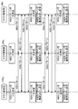
- FIG. 1 is a schematic diagram of a radio communication system according to a first embodiment of the present invention. It is a block diagram which shows the structure of the mobile terminal which concerns on the 1st Embodiment of this invention. It is a block diagram which shows the structure of the macro base station which concerns on the 1st Embodiment of this invention. It is a block diagram which shows the structure of the pico base station which concerns on the 1st Embodiment of this invention. It is a figure which shows the format of the radio
- FIG. 8 is a diagram illustrating subframe appearance patterns different from those in FIG. 6 or 7 in time domain-based inter-cell interference control. It is the schematic which shows the use of a protected sub-frame and a non-protected sub-frame in the time domain base inter-cell interference control.
- 1 is a schematic diagram illustrating an example of an arrangement of a plurality of macro base stations, a plurality of pico base stations, and a plurality of macro cells in a wireless communication system according to the present invention. It is an information flow diagram which shows operation
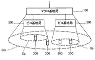
- FIG. 1 is a schematic diagram of a radio communication system according to a first embodiment of the present invention.
- the wireless communication system includes a macro base station (macro eNodeB (evolved Node B)) 100 and a pico base station (pico eNodeB) 200.
- macro base station macro eNodeB (evolved Node B)
- pico eNodeB pico base station
- Each communication element in the wireless communication system is a predetermined wireless access technology (Radio Access ⁇ ⁇ ⁇ Technology), for example, LTE (Long Term Evolution) in 3GPP (Third Generation Partnership Project).
- LTE Long Term Evolution
- 3GPP Third Generation Partnership Project
- the wireless communication system operates according to LTE, but is not intended to limit the technical scope of the present invention.
- the present invention can also be applied to other radio access technologies (for example, WiMAX defined in IEEE 802.16) after making necessary design changes.
- Macro base station (high-power radio base station) 100 and pico base station (low-power radio base station) 200 are connected to each other by wire or wirelessly.
- the macro base station 100 forms a macro cell (first cell) Cm
- each pico base station 200 forms a pico cell (second cell) Cp.
- the pico cell Cp is a cell formed in the macro cell Cm formed by the macro base station 100 connected to the pico base station 200 that forms the pico cell Cp.
- a plurality of pico cells Cp can be formed.
- Each wireless base station can wirelessly communicate with a mobile terminal (UE, User Equipment) 300 located in the cell of the base station itself.
- the mobile terminal 300 can wirelessly communicate with a base station (macro base station 100, pico base station 200) corresponding to a cell (macro cell Cm, pico cell Cp) in which the mobile terminal 300 is located.
- the macro base station 100 Since the macro base station 100 has a higher radio transmission capability (maximum transmission power, average transmission power, etc.) than the pico base station 200, it can communicate with the mobile terminal 300 located farther away. Therefore, the macro cell Cm has a larger area than the pico cell Cp. For example, the macro cell Cm has a radius of several hundred meters to several tens of kilometers, and the pico cell Cp has a radius of several meters to several tens of meters.
- the macro base station 100 and the pico base station 200 in the radio communication system are heterogeneous in which a plurality of types of radio base stations having different transmission powers (transmission capabilities) are installed in multiple layers.
- Configure the network Heterogeneous Network, HetNet).
- the mobile terminal 300 when the mobile terminal 300 is located in the pico cell Cp, the mobile terminal 300 will configure the pico cell Cp to form the pico cell Cp. It can be understood that wireless communication is possible with at least one of the base station 200 and the macro base station 100 forming the macro cell Cm including the pico cell Cp.
- the method of wireless communication between each base station and the mobile terminal 300 is arbitrary.
- OFDMA Orthogonal Frequency Division Multiple Access
- SC-FDMA Single-Carrier Frequency Division Multiple Access
- FIG. 2 is a block diagram showing a configuration of mobile terminal 300 according to the first embodiment of the present invention.
- the mobile terminal 300 includes at least one transmission / reception antenna 312, a wireless communication unit 310, a signal separation unit 320, a control signal demodulation unit 330, a data signal demodulation unit 332, a reception quality measurement unit 334, a reception quality correction unit 336, and a reception quality report unit. 338.
- FIG. 2 illustrations of an output device that outputs audio and video, an input device that receives an instruction from a user, and the like are omitted for convenience.
- the mobile terminal 300 includes a plurality of transmission / reception antennas 312, but may include at least one reception-dedicated antenna and at least one transmission-dedicated antenna.
- the wireless communication unit 310 is an element for performing wireless communication with the wireless base station (the macro base station 100 or the pico base station 200), and converts radio waves received from the wireless base station by the transmission / reception antenna 312 into electric signals.
- the radio communication unit 310 receives connection destination cell information from the macro base station 100 that forms the macro cell Cm in which the mobile terminal 300 is located or the pico base station 200 that forms the pico cell Cp.
- the connection destination cell information is information that designates a radio base station (macro base station 100 or pico base station 200) to which the mobile terminal 300 should be connected. In accordance with the connection destination cell information, the mobile terminal 300 communicates with the connection destination radio base station.
- the signal separation unit 320, the control signal demodulation unit 330, the data signal demodulation unit 332, the reception quality measurement unit 334, the reception quality correction unit 336, and the reception quality report unit 338 are provided by a CPU (Central Processing Unit) not shown in the mobile terminal 300. These are functional blocks realized by executing a computer program stored in a storage unit (not shown) and functioning according to the computer program.
- a CPU Central Processing Unit
- the signal separation unit 320 selects signals addressed to the mobile terminal 300 from the signals processed by the wireless communication unit 310, and further separates these signals into control signals, data signals, and reference signals.
- the control signal demodulator 330 demodulates the control signal.
- the data signal demodulation unit 332 refers to the demodulated control signal, identifies the resource used for transmitting the data signal, and demodulates the data signal.
- the reception quality measurement unit 334 performs reception quality measurement based on the reference signal.
- the reception quality measuring unit 334 not only measures the quality of the reference signal from the desired radio base station to which the mobile terminal 300 is connected, but also the quality of the reference signal from the neighboring radio base stations around the desired radio base station. Also measure. Details of the functions of the reception quality measurement unit 334, the reception quality correction unit 336, and the reception quality report unit 338 will be described later.
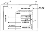
- FIG. 3 is a block diagram showing a configuration of the macro base station 100 according to the first embodiment of the present invention.
- the macro base station 100 includes at least one transmission / reception antenna 112, a radio communication unit 110, an inter-base station communication unit 120, and a control unit 130.
- the macro base station 100 has a plurality of transmission / reception antennas 112, but may have at least one reception-dedicated antenna and at least one transmission-dedicated antenna.
- the wireless communication unit 110 is an element for performing wireless communication with the mobile terminal 300.
- the wireless communication unit 110 converts a radio wave received from the mobile terminal 300 by the transmission / reception antenna 112 into an electrical signal, and an electrical signal such as an audio signal.
- a transmission circuit that converts the signal into a radio wave and transmits the signal through the transmitting / receiving antenna 112.
- the radio communication unit 110 transmits a radio signal indicating connection destination cell information to each mobile terminal 300 located in the macro base station 100.
- the inter-base station communication unit 120 is an element for performing communication with other radio base stations (the macro base station 100 and the pico base station 200), and transmits and receives electrical signals to and from other radio base stations.
- the radio communication unit 110 can also serve as the inter-base station communication unit 120.
- the control unit 130 includes a resource setting unit 134, a communication control unit 136, and a connection destination selection unit 138 as elements.
- the control unit 130, the resource setting unit 134 included in the control unit 130, the communication control unit 136, and the connection destination selection unit 138 are stored in a computer program stored in a storage unit (not shown) by a CPU (not shown) in the macro base station 100. It is a functional block realized by executing and functioning according to the computer program. Details of the operation of the control unit 130 will be described later.
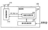
- FIG. 4 is a block diagram showing a configuration of the pico base station 200 according to the first embodiment of the present invention.
- the pico base station 200 includes at least one transmission / reception antenna 212, a wireless communication unit 210, an inter-base station communication unit 220, and a control unit 230.
- the pico base station 200 includes a plurality of transmission / reception antennas 212, but may include at least one reception-dedicated antenna and at least one transmission-dedicated antenna.
- the wireless communication unit 210 is an element for performing wireless communication with the mobile terminal 300.
- the wireless communication unit 210 converts a radio wave received by the transmission / reception antenna 212 from the mobile terminal 300 into an electrical signal, and converts the electrical signal into a radio wave. And a transmission circuit for transmitting by the transmission / reception antenna 212.
- the inter-base station communication unit 220 is an element for executing communication with the macro base station 100 and other radio base stations to which the pico base station 200 itself is connected, and is electrically connected to the macro base station 100 and other radio base stations. Send and receive signals.
- the radio communication unit 210 may also serve as the inter-base station communication unit 220.
- the control unit 230 of the pico base station 200 includes the connection destination selection unit 238 as an element.
- a CPU (not shown) in the pico base station 200 executes a computer program stored in a storage unit (not shown), and the computer program It is a functional block realized by functioning according to. Details of the operation of the control unit 230 will be described later.
- Each reception quality measurement unit 334 of the mobile terminal 300 receives, as radio wave reception quality, radio wave reception power received from the desired radio base station to which the mobile terminal 300 is connected (for example, reference signal reception power. Reference Signal Received). Power, RSRP) and the received power (for example, reference signal received power) of radio waves received from the radio base station to which the mobile terminal 300 is not connected.
- the reception quality measurement unit 334 measures the reception power of the radio wave received from the macro base station 100 and the reception power of the radio wave received from the pico base station 200.
- the received power value of the radio wave from the macro base station 100 is set as the first received power value R1, and whether or not the pico base station 200 is the desired radio base station.
- the received power value of the radio wave from the pico base station 200 is set as the second received power value R2.
- Each reception quality correction unit 336 of the mobile terminal 300 increases the second received power value R2 of the radio wave from the pico base station 200 using a predetermined offset value (bias value) ⁇ .
- bias value may be simply added to R2, or ⁇ may be added to R2 in decibels. In any case, this process improves the reception quality of radio waves from the pico base station 200 in appearance.
- the second received power value R2 corrected in this way is referred to as a corrected second received power value (R2 + ⁇ ).
- the offset value ⁇ is stored in a storage unit (not shown) of the mobile terminal 300, for example.
- the reception quality report unit 338 of the mobile terminal 300 receives a signal indicating the reception power result report including the first reception power value R1 and the corrected second reception power value (R2 + ⁇ ) via the wireless communication unit 310. It transmits to a radio base station (macro base station 100 or pico base station 200).
- the connection destination selection unit 138 of the macro base station 100 selects a radio base station to which the mobile terminal 300 should connect based on the received power result report of each mobile terminal 300. At this time, the connection destination selection unit 138 has the radio base station to which the mobile terminal 300 should connect the radio base station corresponding to the received power value indicating the highest received power (that is, the received quality value indicating the best received quality). Select as station.
- the connection destination selecting unit 138 moves the macro base station 100 to the mobile terminal 300. Select as the connection destination.
- the connection destination selection unit 138 sets the pico base station 200 as the connection destination of the mobile terminal 300. select.
- the connection destination selection unit 138 notifies the mobile terminal 300 connected to the macro base station 100 of connection destination cell information indicating the selected wireless connection destination.
- the connection destination selection unit 138 performs a related radio base station (for example, the pico base station 200 or other in the vicinity) via the inter-base station communication unit 120. To the macro base station 100) that the connection destination of the mobile terminal 300 is changed.
- the connection destination selection unit 238 of the pico base station 200 selects a radio base station to which the mobile terminal 300 should be connected based on the received power result report of each mobile terminal 300. At this time, the connection destination selection unit 238 connects the radio base station corresponding to the received power value indicating the highest received power (that is, the received quality value indicating the best received quality) to which the mobile terminal 300 is connected. Select as station.
- the selection method is the same as the method performed by the connection destination selection unit 138 of the macro base station 100.
- the connection destination selection unit 238 notifies the mobile terminal 300 connected to the pico base station 200 of connection destination cell information indicating the selected wireless connection destination.
- the connection destination selection unit 238 receives a related radio base station (for example, the macro base station 100 or other nearby ones) via the inter-base station communication unit 120. To the macro base station 100) that the connection destination of the mobile terminal 300 is changed.
- the wireless communication unit 310 of the mobile terminal 300 receives the connection destination cell information.
- the connection destination cell information indicates a radio base station to which the mobile terminal 300 is already connected
- the mobile terminal 300 maintains the connection.
- the connection destination cell information indicates another radio base station
- the mobile terminal 300 executes a connection operation to that radio base station. For example, when the mobile terminal 300 is connected to the macro base station 100 and the mobile terminal 300 receives connection destination cell information specifying the pico base station 200 as a connection destination, the mobile terminal 300 The mobile terminal 300 itself is connected (offloaded) to the station 200.
- the reception power value R2 of the radio wave from the pico base station 200 As described above, as a result of correcting the reception power value R2 of the radio wave from the pico base station 200 with the offset value ⁇ , the reception quality of the radio wave from the pico base station 200 is apparently improved. For this reason, the radius of the pico cell Cp and the range thereof are expanded, and the processing load on the macro base station 100 is reduced accordingly.
- the macro base station 100 can perform radio transmission to the mobile terminal 300 using the same resource (specified by frequency and time) used by the pico base station 200 in the macro cell Cm. At the same time, it is configured to cooperate with these pico base stations 200 for eICIC (enhanced inter-cell interference control).
- eICIC enhanced inter-cell interference control
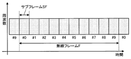
- FIG. 5 is a diagram showing a format of a radio frame F transmitted / received between the communication elements of the radio communication system.
- the radio frame F is a transmission unit of a radio signal transmitted by each communication element (the macro base station 100, the pico base station 200, and the mobile terminal 300), and has a predetermined time length (for example, 10 milliseconds) and a predetermined bandwidth. Occupy.
- a series of radio signals is formed by continuously transmitting the radio frames F.
- the radio frame F includes a plurality of subframes SF.
- the subframe SF is a transmission unit occupying a shorter time length (for example, 1 millisecond) than the radio frame F, and can be numbered in ascending order from No. 0 (# 0) in one radio frame F.
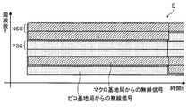
- FIG. 6 is a diagram showing an outline of time domain-based eICIC.
- the macro base station 100 and the pico base station 200 that forms the pico cell Cp in the macro cell Cm formed by the macro base station 100 use the same radio frame timing and the same frequency band as radio signals.
- (radio frame F) is transmitted.
- “radio signals are transmitted at the same radio frame timing” means that the transmission start time of the radio frame F transmitted by the macro base station 100 and the transmission start time of the radio frame F transmitted by the pico base station 200 Means simultaneous. That is, the radio communication unit 110 of the macro base station 100 and the radio communication unit 210 of the pico base station 200 can execute radio communication in synchronization.
- the radio signal from the macro base station 100 and the radio signal from the pico base station 200 are transmitted in the same frequency band, they interfere with each other.
- the transmission power of the macro base station 100 is larger than the transmission power of the pico base station 200
- the interference of the radio signal from the macro base station 100 with respect to the radio signal from the pico base station 200 is significantly large. Therefore, if both radio signals are constantly transmitted, it is difficult for the mobile terminal 300 having the pico base station 200 as a desired base station to receive the radio signal from the pico base station 200.
- the pico base station 200 continuously performs downlink transmission, while the macro base station 100 intermittently performs downlink transmission.
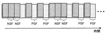
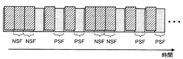
- the macro base station 100 switches between radio signal transmission execution and transmission stop for each subframe SF. Since the radio signal of the pico base station 200 is protected (protected) from interference by the macro base station 100, the subframe SF in which the macro base station 100 stops transmitting the radio signal is referred to as a protected subframe PSF. Conversely, a subframe SF in which the macro base station 100 executes transmission of a radio signal is referred to as a non-protected subframe NSF.
- the radio communication unit 110 of the macro base station 100 does not transmit a radio signal
- only the radio communication unit 210 of the pico base station 200 transmits a radio signal. Therefore, in the protected subframe PSF, since the radio signal from the pico base station 200 is not interfered by the radio signal from the macro base station 100, the mobile terminal 300 located in the pico cell Cp formed by the pico base station 200 is used. However, the radio signal from the pico base station 200 can be received with higher quality.
- the protected subframe PSF and the non-protected subframe NSF appear alternately, but the appearance pattern of the protected subframe PSF and the non-protected subframe NSF is not limited to that illustrated in FIG. Rather, as shown in FIGS. 7 and 8, the appearance pattern of the protected subframe PSF and the non-protected subframe NSF can be changed.
- This appearance pattern is called an ABS (Almost Blank Subframe) pattern in LTE (for example, 3GPP TS 36.300 V10.5.0, 3GPP TS 36.423 V11.0.0).
- the ABS pattern includes a non-protected subframe NSF (first resource) that the radio communication unit 110 of the macro base station 100 should perform radio transmission and the radio communication unit 110 of the macro base station 100 should stop radio transmission.
- one protected subframe PSF appears within a period of 8 subframes.
- one of the eight subframes is a protected subframe PSF.
- the ratio of the protected subframe PSF (second resource) to the total number of protected subframes PSF (second resource) to be stopped is 1/8.
- this ABS pattern is referred to as an ABS pattern having a ratio of 1/8.
- ABS pattern shown in FIG. 8 three protected subframes PSF appear within a period of 8 subframes. In other words, three of the eight subframes are protected subframes PSF.
- the ratio of the protected subframe PSF (second resource) to the total number of protected subframes PSF (second resource) to be stopped is 3/8.
- this ABS pattern is referred to as an ABS pattern having a ratio of 3/8.
- an ABS pattern in which n out of 8 subframes are protected subframes PSF is referred to as an n / 8 ABS pattern (n is a positive integer).
- This embodiment is based on time domain-based eICIC, and the resource setting unit 134 of the macro base station 100 sets an ABS pattern based on parameters to be described later.
- the resource setting unit 134 performs the second communication for the radio communication unit 110 of the macro base station 100 to stop radio communication for a unit resource (radio frame F) that occupies a predetermined time length and a predetermined frequency bandwidth.
- the ratio of resources (protected subframe PSF) is set.
- the resource setting unit 134 determines the number of non-protected subframes NSF (first resources) to be transmitted by the wireless communication unit 110 of the macro base station 100 and the wireless communication of the macro base station 100.
- the unit 110 sets the ratio of the protected subframe PSF (second resource) to the total number of protected subframes PSF (second resource) for which radio transmission should be stopped.
- the resource setting unit 134 When the resource setting unit 134 sets the ABS pattern, that is, the above ratio, the resource setting unit 134 generates the resource allocation information AL based on the ABS pattern.
- the resource allocation information AL is information (information indicating the number and arrangement of protected subframes PSF) indicating an ABS pattern.
- the resource setting unit 134 supplies the resource allocation information AL to the communication control unit 136.
- the communication control unit 136 controls the wireless communication unit 110 based on the resource distribution information AL. That is, the wireless communication unit 110 performs wireless communication in the non-protected subframe NSF set by the resource setting unit 134, and stops wireless communication in the protected subframe PSF set by the resource setting unit 134.
- the unit 110 is controlled.
- the control unit 230 of the pico base station 200 performs downlink resource allocation, that is, scheduling to the mobile terminal 300 connected to the pico base station 200 according to, for example, a proportional fairness algorithm.
- a proportional fairness type scheduler uses the proportional fairness type scheduler to perform wireless communication to the mobile terminal 300 in the center of the picocell Cp (the mobile terminal 300 connected to the pico base station 200 without the expansion of the picocell Cp by CRE).
- the non-protected subframe NSF is mainly used, and the mobile terminal 300 at the end of the pico cell Cp (the mobile terminal 300 connected to the pico base station 200 due to the expansion of the pico cell Cp by CRE) is used.
- Protected subframe PSF is mainly used for radio communication.
- the resource setting unit 134 of the macro base station 100 may transmit the resource allocation information AL to the pico base station 200 by the inter-base station communication unit 120, and the inter-base station communication unit 220 of the pico base station 200 Upon receiving the information AL, the control unit 230 of the pico base station 200 may perform resource allocation to the mobile terminal 300 based on the resource allocation information.
- the non-protected subframe NSF is mainly used for radio communication to the mobile terminal 300 in the center of the picocell Cp (the mobile terminal 300 connected to the pico base station 200 even if the picocell Cp is not expanded by the CRE).
- the control unit 230 may control the wireless communication unit 210.
- the control unit 230 For wireless communication to the mobile terminal 300 at the end of the pico cell Cp (the mobile terminal 300 connected to the pico base station 200 due to the expansion of the pico cell Cp by CRE), the control unit 230 is used to use the protected subframe PSF. May control the wireless communication unit 210. As an index of the distance between the mobile terminal 300 and the pico base station 200, the corrected second received power value (R2 + ⁇ ) or the second received power value indicated in the received power result report received by the pico base station 200 from the mobile terminal 300 is used. R2 can be used.
- the control unit 230 may control the wireless communication unit 210 to use the protected subframe PSF for wireless communication to the mobile terminal 300 having the second received power value R2 lower than the threshold.
- the control unit 230 may control the wireless communication unit 210 to use the non-protected subframe NSF for wireless communication with the mobile terminal 300 having the second received power value R2 higher than the threshold.
- FIG. 9 shows uses of the protected subframe PSF and the non-protected subframe NSF.
- the radio signal from the macro base station 100 stops in the non-protected subframe NSF, and the radio signal is transmitted from the macro base station 100 in the protected subframe PSF.
- the pico base station 200 wirelessly transmits mainly to the mobile terminal 300 in the center of the pico cell Cp (the mobile terminal 300 connected to the pico base station 200 even if the pico cell Cp is not expanded by the CRE).
- the pico base station 200 mainly performs radio transmission to the mobile terminal 300 at the end of the pico cell Cp (the mobile terminal 300 connected to the pico base station 200 due to the expansion of the pico cell Cp by CRE). .
- EICIC limits the resources available at the macro base station.
- the second resource (protected subframe PSF) that cannot be used by the macro base station 100 is used. It is not desirable to set the amount large.
- the first resource (non-protected subframe NSF) available in the macro base station 100 is used. ) Is not desirable to set a large amount.
- the resource setting unit 134 of the macro base station 100 applies CRE to the total number of mobile terminals 300 that exist in the macro cell (first cell) Cm and are actually connected to the macro base station 100 or the pico base station 200.
- the first base station is a ratio of the number of mobile terminals 300 that will connect to the macro base station 100 without connecting to the pico base station 200 but actually connect to the pico base station 200 by applying CRE.
- the resource setting unit 134 of the macro base station 10 determines the number of protected subframes PSF corresponding to the total number of non-protected subframes NSF and the number of protected subframes PSF in the macro base station 100 according to Equation (1).
- the provisional ratio r is calculated.
- each parameter is as follows.
- Ratio of user apparatuses 300 actually connected to the station 200 that is, the macro cell Cm when the CRE is applied to the total number of mobile terminals 300 existing in the macro cell Cm and actually connected to the macro base station 100 or the pico base station 200
- P p (0) All pico bases in the macro cell Cm when the offset value of the CRE is 0 dB with respect to the total number of mobile terminals 300 existing in the macro cell Cm and actually connected to the macro base station 100 or the pico base station 200
- Ratio of user equipments 300 connected to the station 200 ie, the total number of mobile terminals 300 existing in the macrocell Cm and actually connected to the macro base station 100 or the pico base station 200 when all CREs are not applied
- P m ( ⁇ ) actually connected to the macro base station 100 when the CRE offset value is ⁇ dB with respect to the total number of mobile terminals 300 existing in the macro cell Cm and actually connected to the macro base station 100 or the pico base station 200
- Ratio of user equipment 300 to be connected that is, actually connected to the macro base station 100 when CRE is applied to the total number of mobile terminals 300 existing in the macro cell Cm and actually connected to the macro base station 100 or the pico base station 200
- Ratio of the number of mobile terminals 300 to be used Ratio of the number of mobile terminals 300 to be used).
- N p / m the number of pico base stations 200 in the macro base station 100.
- ⁇ Correction coefficient.
- the rate P p ( ⁇ ) is actually in the pico base station 200 with respect to the total number of mobile terminals 300 present in the macro cell Cm and actually connected to the macro base station 100 or the pico base station 200. This is the ratio of the number of all mobile terminals 300 to be connected.
- the control unit 130 of the macro base station 100 recognizes the number N m ( ⁇ ) of the mobile terminals 300 that are actually connected to the macro base station 100. That is, the control unit 130 of the macro base station 100 functions as a counting unit that counts the number N m ( ⁇ ). Further, the control unit 230 of each pico base station 200 recognizes the number N pi ( ⁇ ) of mobile terminals 300 that are actually connected to the pico base station 200.
- control unit 230 of each pico base station 200 functions as a counting unit that counts the number N pi ( ⁇ ).
- the control unit 230 of each pico base station 200 reports the number N pi ( ⁇ ) to the control unit 130 of the macro base station 100.
- the control unit 130 functions as a rate calculating unit that calculates the rate P p ( ⁇ ) according to the equation (2).
- the reason for obtaining the sum of the numbers N pi ( ⁇ ) is that a plurality of pico base stations 200 can exist in the pico cell Cp of the macro base station 100.
- the ratio P p (0) is the number of mobile terminals 300 that actually exist in the center of the pico cell Cp with respect to the total number of mobile terminals 300 that exist in the macro cell Cm and actually connect to the macro base station 100 or the pico base station 200 (pico cells by the CRE). This is the ratio of the number of mobile terminals 300) connected to the pico base station 200 without Cp expansion.
- the control unit 230 of the pico base station 200 identifies the mobile terminal 300 actually located in the center of the pico cell Cp from the mobile terminals 300 actually located at the end of the pico cell Cp by comparing the second received power value R2 and the threshold value. be able to.
- the mobile terminal 300 that is actually in the center of the pico cell Cp is the mobile terminal 300 whose second received power value R2 is higher than the threshold, and the mobile terminal 300 that is actually at the end of the pico cell Cp.
- the mobile terminal 300 has a second received power value R2 lower than a threshold value.
- the control unit 230 of each pico base station 200 compares the second received power value R2 with the threshold value, and the mobile terminal 300 with the second received power value R2 higher than the threshold value and the mobile terminal 300 with the second received power value R2 lower than the threshold value. It functions as a mobile terminal classification unit that distinguishes from the terminal 300.
- control unit 230 of each pico base station 200 functions as a counting unit that counts the number N pi (0) of the mobile terminals 300 that are actually in the center of the pico cell Cp of the pico base station 200, and the number N pi ( 0) is reported to the control unit 130 of the macro base station 100.
- the control unit 130 functions as a rate calculating unit that calculates the rate P p (0) according to the equation (3).
- the first ratio (P p ( ⁇ ) ⁇ P p (0)) can be calculated from the ratios P p ( ⁇ ) and P p (0).
- the control unit 130 thus functions as a ratio calculation unit that calculates the first ratio (P p ( ⁇ ) ⁇ P p (0)).
- the first ratio (P p ( ⁇ ) ⁇ P p (0)) may be calculated as follows.
- the first ratio (P p ( ⁇ ) ⁇ P p (0)) is an end of the pico cell Cp with respect to the total number of mobile terminals 300 existing in the macro cell Cm and actually connected to the macro base station 100 or the pico base station 200.
- the mobile terminal 300 actually connected to the mobile terminal 300 (if the CRE is not applied, the mobile terminal 300 will be connected to the macro base station 100 without being connected to the pico base station 200. It is a ratio of the number of mobile terminals 300) to be connected.
- the control unit 230 of the pico base station 200 can identify the mobile terminal 300 at the end of the pico cell Cp from the mobile terminal 300 at the center of the pico cell Cp by comparing the second received power value R2 with the threshold. More specifically, the mobile terminal 300 that is actually in the center of the pico cell Cp is the mobile terminal 300 whose second received power value R2 is higher than the threshold, and the mobile terminal 300 that is actually at the end of the pico cell Cp. The mobile terminal 300 has a second received power value R2 lower than a threshold value.
- the control unit 230 of each pico base station 200 compares the second received power value R2 with the threshold value, and the mobile terminal 300 with the second received power value R2 higher than the threshold value and the mobile terminal 300 with the second received power value R2 lower than the threshold value. It functions as a mobile terminal classification unit that distinguishes from the terminal 300. Further, the control unit 230 of each pico base station 200 functions as a counting unit that counts the number N ppi of the mobile terminals 300 that are actually at the end of the pico cell Cp of the pico base station 200, and uses the number N ppi as the macro base. You may report to the control part 130 of the station 100. The control unit 130 may function as a rate calculating unit that calculates the first rate (P p ( ⁇ ) ⁇ P p (0)) according to the equation (4).
- the second ratio P m ( ⁇ ) is the macro base station 100 with respect to the total number of mobile terminals 300 that exist in the macro cell Cm and actually connect to the macro base station 100 or the pico base station 200. It is the ratio of the number of all the mobile terminals 300 actually connected to.
- the control unit 130 may function as a ratio calculation unit that calculates the second ratio P m ( ⁇ ) according to the equation (5).
- the first ratio (P p ( ⁇ ) ⁇ P p (0)) and the second ratio P m ( ⁇ ), which are parameters of equation (1), are calculated in this way. Since the remaining parameters N p / m and ⁇ are constants, the resource setting unit 134 can calculate the provisional ratio r according to Equation (1).
- the provisional ratio r can be a continuous value, but the actual ratio of the protected subframe PSF is a discrete value (in the above example, 0/8, 1/8, 2/8, 3/8, ). Therefore, the resource setting unit 134, according to the equation (6) using the floor function, the ratio R (number of protected subframes PSF to the total number of non-protected subframes NSF and the number of protected subframes PSF) Discrete value).
- the resource setting unit 134 performs the ratio R of the number of protected subframes PSF to the total number of non-protected subframes NSF and the number of protected subframes PSF according to Equation (7) using the ceiling function. (Discrete value) may be calculated.
- L represents the period of the ABS pattern (8 in the above example).
- the resource setting unit 134 determines the ratio R (discrete value, 0 in the above example) of the number of protected subframes PSF to the total number of non-protected subframes NSF and the number of protected subframes PSF. / 8, 1/8, 2/8, 3/8,...), And an ABS pattern corresponding to the ratio R is set.
- the non-protected subframe NSF is a period during which a radio signal is transmitted from the macro base station 100. If the CRE is not applied, the protected subframe PSF will connect to the macro base station 100 without being connected to the pico base station 200. However, the protected subframe PSF is actually connected to the pico base station 200 by applying the CRE. This is a period during which a radio signal is transmitted from the pico base station 200 mainly to the terminal 300 (the mobile terminal 300 actually located at the end of the pico cell Cp).
- the ratio R to be set by the connection destination selection unit 138 is the ratio of the protected subframe PSF to the total number of non-protected subframes NSF and the number of protected subframes PSF.
- the second ratio P m ( ⁇ ) is determined when the CRE is applied to the total number of mobile terminals 300 existing in the macro cell Cm and actually connected to the macro base station 100 or the pico base station 200. This is the ratio of the number of mobile terminals 300 that are actually connected to the base station 100. It can be considered that the second ratio P m ( ⁇ ) corresponds to the non-protected subframe NSF.
- the first ratio (P p ( ⁇ ) ⁇ P p (0)) is an end of the pico cell Cp with respect to the total number of mobile terminals 300 existing in the macro cell Cm and actually connected to the macro base station 100 or the pico base station 200.
- the mobile terminal 300 actually connected to the mobile terminal 300 (if the CRE is not applied, the mobile terminal 300 will be connected to the macro base station 100 without being connected to the pico base station 200. It is a ratio of the number of mobile terminals 300) to be connected.
- the first ratio (P p ( ⁇ ) ⁇ P p (0)) can be considered to correspond to the protected subframe PSF.
- the provisional ratio r is preferably calculated according to the equation (8).
- the correction coefficient ⁇ in the equation (1) is simply equal to N p / m .
- the macro base station 100 cannot use them.
- the amount of possible second resources (protected subframe PSF) can be set small, and the amount of the first resource (non-protected subframe NSF) available in the macro base station 100 can be set large.
- the macro base station 100 cannot use them.
- the amount of possible second resources (protected subframe PSF) can be set large, and the amount of the first resource (non-protected subframe NSF) available in the macro base station 100 can be set small. Therefore, the amount of resources that can be used in the macro base station 100 can be appropriately controlled in accordance with the actual usage status of the radio base stations 100 and 200. From the viewpoint of the mobile terminal 300, the fairness of resource allocation to the mobile terminal 300 connected to the macro base station 100 and the mobile terminal 300 connected to the pico base station 200 is improved, and which radio base station is connected to? Can prevent the throughput from deteriorating.
- the macro base station 100 is connected to the number of mobile terminals 300 existing in the entire macro cell Cm of the macro base station 100 and connected to the macro base station 100, and to the pico base station 200 in the entire macro cell Cm. Based on the number of mobile terminals 300 to perform, an ABS pattern used in the macro cell Cm is set. However, the macro base station 100 includes the number of mobile terminals 300 that exist in one sector of the macro cell Cm of the macro base station 100 and connect to the macro base station 100, and the mobile terminals that connect to the pico base station 200 in the sector. Based on the number of 300, the ABS pattern used in the sector may be set. That is, the macro base station 100 may set an optimum ABS pattern for each sector constituting the macro cell Cm.
- the second embodiment is different from the first embodiment in the method of setting the ratio R by the resource setting unit 134 of the macro base station 100.
- the configurations of the macro base station 100, the pico base station 200, and the mobile terminal 300 may be the same as those in the first embodiment.
- Features common to the first embodiment will not be described in detail.
- the resource setting unit 134 of the macro base station 100 will connect to the macro base station 100 without connecting to the pico base station 200, but the CRE is applied.
- the ratio R of the number of protected subframes PSF to the total number of non-protected subframes NSF and the number of protected subframes PSF is set to be smaller.
- the resource setting unit 134 of the macro base station 10 determines the number of protected subframes PSF with respect to the total number of non-protected subframes NSF and the number of protected subframes PSF in the macro base station 100 according to Equation (9).
- the provisional ratio r is calculated.
- N p ( ⁇ ) the number of user equipments 300 actually connected to all the pico base stations 200 in the macro cell Cm of the macro base station 100 when the CRE offset value is ⁇ dB (that is, the macro cell when the CRE is applied)
- N p (0) the number of user equipments 300 connected to all the pico base stations 200 in the macro cell Cm of the macro base station 100 when the CRE offset value is 0 dB (that is, in the macro cell Cm when the CRE is not applied) Number of mobile terminals 300 connected to all pico base stations 200).
- N m ( ⁇ ) the number of user equipments 300 actually connected to the macro base station 100 when the CRE offset value is ⁇ dB (that is, the mobile terminal 300 actually connected to the macro base station 100 when the CRE is applied) Number).
- N p / m the number of pico base stations 200 in the macro base station 100.
- ⁇ Correction coefficient.
- the second number N m ( ⁇ ) is the number of all mobile terminals 300 that are actually connected to the macro base station 100.
- the control unit 130 of the macro base station 100 recognizes the number N m ( ⁇ ) of the mobile terminals 300 that are actually connected to the macro base station 100. That is, the control unit 130 of the macro base station 100 functions as a counting unit that counts the number N m ( ⁇ ).
- the number N p ( ⁇ ) is the number of all mobile terminals 300 that are actually connected to the pico base station 200.
- the control unit 230 of each pico base station 200 recognizes the number N pi ( ⁇ ) of mobile terminals 300 that are actually connected to the pico base station 200. That is, the control unit 230 of each pico base station 200 functions as a counting unit that counts the number N pi ( ⁇ ).
- the control unit 230 of each pico base station 200 reports the number N pi ( ⁇ ) to the control unit 130 of the macro base station 100.
- the control unit 130 functions as a number calculation unit that calculates the number N p ( ⁇ ) according to the equation (10).
- the number N p (0) is the number of mobile terminals 300 that actually exist in the center of the pico cell Cp (the mobile terminals 300 that are connected to the pico base station 200 even if the pico cell Cp is not expanded by the CRE).
- the control unit 230 of the pico base station 200 identifies the mobile terminal 300 actually located in the center of the pico cell Cp from the mobile terminals 300 actually located at the end of the pico cell Cp by comparing the second received power value R2 and the threshold value. be able to. More specifically, the mobile terminal 300 that is actually in the center of the pico cell Cp is the mobile terminal 300 whose second received power value R2 is higher than the threshold, and the mobile terminal 300 that is actually at the end of the pico cell Cp.
- the mobile terminal 300 has a second received power value R2 lower than a threshold value.
- the control unit 230 of each pico base station 200 compares the second received power value R2 with the threshold value, and the mobile terminal 300 with the second received power value R2 higher than the threshold value and the mobile terminal 300 with the second received power value R2 lower than the threshold value. It functions as a mobile terminal classification unit that distinguishes from the terminal 300. Further, the control unit 230 of each pico base station 200 functions as a counting unit that counts the number N pi (0) of the mobile terminals 300 that are actually in the center of the pico cell Cp of the pico base station 200, and the number N pi ( 0) is reported to the control unit 130 of the macro base station 100.
- the control unit 130 functions as a number calculation unit that calculates the number N p (0) according to the equation (11).
- the first number (N p ( ⁇ ) ⁇ N p (0)) can be calculated from the numbers N p ( ⁇ ) and N p (0).
- the control unit 130 functions as a number calculation unit that calculates the first number (N p ( ⁇ ) ⁇ N p (0)).
- the first number (N p ( ⁇ ) ⁇ N p (0)) may be calculated as follows.
- the first number (N p ( ⁇ ) ⁇ N p (0)) is the mobile terminal 300 actually located at the end of the pico cell Cp (the macro base station without being connected to the pico base station 200 if CRE is not applied).
- the control unit 230 of the pico base station 200 can identify the mobile terminal 300 at the end of the pico cell Cp from the mobile terminal 300 at the center of the pico cell Cp by comparing the second received power value R2 with the threshold.
- the mobile terminal 300 that is actually in the center of the pico cell Cp is the mobile terminal 300 whose second received power value R2 is higher than the threshold, and the mobile terminal 300 that is actually at the end of the pico cell Cp.
- the mobile terminal 300 has a second received power value R2 lower than a threshold value.
- the control unit 230 of each pico base station 200 compares the second received power value R2 with the threshold value, and the mobile terminal 300 with the second received power value R2 higher than the threshold value and the mobile terminal 300 with the second received power value R2 lower than the threshold value. It functions as a mobile terminal classification unit that distinguishes from the terminal 300.
- control unit 230 of each pico base station 200 functions as a counting unit that counts the number N ppi of the mobile terminals 300 that are actually at the end of the pico cell Cp of the pico base station 200, and uses the number N ppi as the macro base. You may report to the control part 130 of the station 100.
- the control unit 130 may function as a number calculation unit that calculates the first number (N p ( ⁇ ) ⁇ N p (0)) according to the equation (12).
- the first number (N p ( ⁇ ) ⁇ N p (0)) and the second number N m ( ⁇ ), parameters of equation (9), are thus calculated. Since the remaining parameters N p / m and ⁇ are constants, the resource setting unit 134 can calculate the provisional ratio r according to Equation (9).
- the provisional ratio r can be a continuous value, but the actual ratio of the protected subframe PSF is a discrete value (in the above example, 0/8, 1/8, 2/8, 3/8, ). Therefore, the resource setting unit 134 performs the ratio of the number of protected subframes PSF to the total number of non-protected subframes NSF and the number of protected subframes PSF according to the above equation (6) using the floor function. R (discrete value) is calculated. Instead, the resource setting unit 134 calculates the number of protected subframes PSF with respect to the total number of non-protected subframes NSF and the number of protected subframes PSF according to the above equation (7) using the ceiling function.
- the ratio R (discrete value) may be calculated.
- the resource setting unit 134 determines the ratio R (discrete value, 0 in the above example) of the number of protected subframes PSF to the total number of non-protected subframes NSF and the number of protected subframes PSF. / 8, 1/8, 2/8, 3/8,...), And an ABS pattern corresponding to the ratio R is set.
- the non-protected subframe NSF is a period during which a radio signal is transmitted from the macro base station 100. If the CRE is not applied, the protected subframe PSF will connect to the macro base station 100 without being connected to the pico base station 200. However, the protected subframe PSF is actually connected to the pico base station 200 by applying the CRE. This is a period during which a radio signal is transmitted from the pico base station 200 mainly to the terminal 300 (the mobile terminal 300 actually located at the end of the pico cell Cp).
- the ratio R to be set by the connection destination selection unit 138 is the ratio of the protected subframe PSF to the total number of non-protected subframes NSF and the number of protected subframes PSF.
- the second number N m ( ⁇ ) is the number of mobile terminals 300 that are actually connected to the macro base station 100 when the CRE is applied.
- the second number N m ( ⁇ ) can be considered to correspond to a non-protected subframe NSF.
- the first number (N p ( ⁇ ) ⁇ N p (0)) is the mobile terminal 300 actually located at the end of the pico cell Cp (the macro base station without being connected to the pico base station 200 if CRE is not applied).
- the first number (N p ( ⁇ ) ⁇ N p (0)) can be considered to correspond to the protected subframe PSF.
- the provisional ratio r is preferably calculated according to the equation (13).
- the correction coefficient ⁇ in Equation (9) is simply equal to N p / m .
- a ratio R of the number of protected subframes PSF to the total number of subframes PSF can be set small.
- the amount of possible second resources (protected subframe PSF) can be set small, and the amount of the first resource (non-protected subframe NSF) available in the macro base station 100 can be set large.
- the macro base station 100 cannot use them.
- the amount of possible second resources (protected subframe PSF) can be set large, and the amount of the first resource (non-protected subframe NSF) available in the macro base station 100 can be set small. Therefore, the amount of resources that can be used in the macro base station 100 can be appropriately controlled in accordance with the actual usage status of the radio base stations 100 and 200. From the viewpoint of the mobile terminal 300, the fairness of resource allocation to the mobile terminal 300 connected to the macro base station 100 and the mobile terminal 300 connected to the pico base station 200 is improved, and which radio base station is connected to? Can prevent the throughput from deteriorating.
- the macro base station 100 is connected to the number of mobile terminals 300 existing in the entire macro cell Cm of the macro base station 100 and connected to the macro base station 100, and to the pico base station 200 in the entire macro cell Cm. Based on the number of mobile terminals 300 to perform, an ABS pattern used in the macro cell Cm is set. However, the macro base station 100 includes the number of mobile terminals 300 that exist in one sector of the macro cell Cm of the macro base station 100 and connect to the macro base station 100, and the mobile terminals that connect to the pico base station 200 in the sector. Based on the number of 300, the ABS pattern used in the sector may be set. That is, the macro base station 100 may set an optimum ABS pattern for each sector constituting the macro cell Cm.
- the third embodiment is a modification of the first embodiment.
- the configurations of the macro base station 100, the pico base station 200, and the mobile terminal 300 may be the same as those in the first embodiment.
- Features common to the first embodiment will not be described in detail.
- the resource setting unit 134 of the macro base station 100 has a usage rate based on the actual usage rate of the resource in the macro base station 100.
- the resource setting unit 134 of the macro base station 10 determines the number of protected subframes PSF with respect to the total number of non-protected subframes NSF and the number of protected subframes PSF in the macro base station 100 according to Expression (14).
- the provisional ratio r is calculated.
- the first ratio (P p ( ⁇ ) ⁇ P p (0)) and the second ratio P m ( ⁇ ) can be calculated by the method described above in connection with the first embodiment.
- the correction coefficient ⁇ in equation (9) is preferably simply equal to N p / m , but it depends on the location of each pico base station 200, the radio wave propagation environment around each pico base station 200, and other factors. Thus, a more appropriate correction coefficient ⁇ can be determined.
- the parameter U m is an actual usage rate of resources in the macro base station 100.
- the non-protected subframe NSF is assigned to the macro base station 100 for radio transmission to the mobile terminal 300 connected to the macro base station 100.
- each subframe is divided into a plurality of resource elements (identified by frequency and time) which are smaller transmission units.
- the macro base station 100 executes scheduling for assigning these resource elements to signals addressed to each mobile terminal 300.
- the usage rate U m is the ratio of the number of resource elements actually allocated to signals addressed to each mobile terminal 300 in the macro base station 100 to the number of all resource elements constituting the non-protected subframe NSF.
- the usage rate U m may be an instantaneous current usage rate, an average value or a median value of several usage rates calculated in the past, or some usage rates calculated in the past and the current value. The average or median usage rate may be used.
- the control unit 130 of the macro base station 100 uses the ratio of the number of resource elements actually allocated to the signal addressed to each mobile terminal 300 to the number of all resource elements constituting the non-protected subframe NSF. It functions as a usage rate calculation unit that calculates a usage rate U m .
- the resource setting unit 134 can calculate the provisional ratio r according to the equation (14).
- the provisional ratio r can be a continuous value, but the actual ratio of the protected subframe PSF is a discrete value (in the above example, 0/8, 1/8, 2/8, 3/8, ). Therefore, the resource setting unit 134 performs the ratio of the number of protected subframes PSF to the total number of non-protected subframes NSF and the number of protected subframes PSF according to the above equation (6) using the floor function.
- R discrete value
- the resource setting unit 134 calculates the number of protected subframes PSF with respect to the total number of non-protected subframes NSF and the number of protected subframes PSF according to the above equation (7) using the ceiling function.
- the ratio R discrete value
- the resource setting unit 134 determines the ratio R (discrete value, 0 in the above example) of the number of protected subframes PSF to the total number of non-protected subframes NSF and the number of protected subframes PSF. / 8, 1/8, 2/8, 3/8,...), And an ABS pattern corresponding to the ratio R is set.
- the reason why the resource usage rate U m of the macro base station 100 is multiplied in the equation (14) is as follows.
- the ratio R of the protected subframe PSF is deliberately low (for the non-protected subframe NSF used in the macro base station 100).
- the ratio R of the protected subframe PSF is deliberately low (for the non-protected subframe NSF used in the macro base station 100).
- the macro base station 100 transmits the mobile terminal 300 connected to the pico base station 200 from the macro base station 100 both in the protected subframe PSF and in the non-protected subframe NSF. The interference caused by the radio waves is eliminated.
- the non-protected subframe for the mobile terminal 300 connected to the pico base station 200 is equivalent to the protected subframe PSF, regardless of the distance from the pico base station 200 to the mobile terminal 300 (regardless of the magnitude of the second received power value R2 of the mobile terminal 300).
- the non-protected subframe NSF can be used for radio transmission to any mobile terminal 300.
- the second embodiment may be modified by applying the same concept. That is, the resource setting unit 134 of the macro base station 10 performs the protected subframe with respect to the total number of the number of non-protected subframes NSF and the number of protected subframes PSF in the macro base station 100 according to Expression (15).
- the provisional ratio r of PSF may be calculated.
- Equation (15) the meaning of each parameter other than U m has been described above in connection with equation (9).
- the first number (N p ( ⁇ ) ⁇ N p (0)) and the second number N m ( ⁇ ) can be calculated by the method described above in connection with the second embodiment.
- the correction coefficient ⁇ in equation (15) is preferably simply equal to N p / m , but it depends on the location of each pico base station 200, the propagation environment of radio waves around each pico base station 200, and other factors. Thus, a more appropriate correction coefficient ⁇ can be determined.
- the resource setting unit 134 calculates the total number of the number of non-protected subframes NSF and the number of protected subframes PSF according to the above equation (6) using the floor function or the above equation (7) using the ceiling function.
- a ratio R (discrete value) of the number of protected subframes PSFs to may be calculated.
- the resource setting section 134 of the macro base station 100 based on the usage rate U m of the resource in the macro base station 100, as the usage rate U m is small, the number of non-protection Ted subframe NSF Protection
- a ratio R of the number of protected subframes PSF to the total number of protected subframes PSF can be set small.
- the ratio R determined by the resource setting unit 134 of the macro base station 100 and the ABS pattern corresponding thereto are used as they are. That is, the communication control unit 136 of the macro base station 100 controls the radio communication unit 110 based on the resource allocation information AL corresponding to this ABS pattern.
- the control unit 230 of the pico base station 200 in the macro cell Cm of the macro base station 100 performs downlink resource allocation, that is, scheduling to the mobile terminal 300 connected to the pico base station 200 according to, for example, a proportional fairness algorithm.
- the wireless communication unit 210 is controlled.
- the control unit 230 of the pico base station 200 may control the radio communication unit 210 based on the resource allocation information AL.
- the macro base station 100 determines the ratio R once determined by the macro base station 100 in the past with other macro base stations 100 around the macro base station 100.
- the ABS pattern corresponding to the corrected ratio AR may be used after correction based on the ratio R once determined.
- a fourth embodiment of the present invention will be described.
- the configurations of the macro base station 100, the pico base station 200, and the mobile terminal 300 may be the same as those of the first embodiment.
- the resource setting unit 134 of the macro base station 100 uses the techniques of the first to third embodiments to set the number of protected subframes PSF with respect to the total number of non-protected subframes NSF and the number of protected subframes PSF.
- a number ratio R is once determined, and an ABS pattern corresponding to the ratio R is once determined.
- FIG. 10 is a schematic diagram illustrating an example of arrangement of a plurality of macro base stations 100, a plurality of pico base stations 200, and a plurality of macro cells Cm in the wireless communication system according to the present invention. At least one pico base station 200 is arranged in the macro cell Cm formed by each macro base station 100. In FIG. 10, a plurality of macro cells Cm do not overlap, but naturally the macro cells Cm may overlap each other.
- each of the several pico base stations 200 is configured to communicate with two adjacent macro base stations 100 (common low power radio).
- Each of a plurality of macro base stations 100 is configured to communicate with a plurality of common pico base stations 200.
- the pico base station 20001 is a common pico base station for two adjacent macro base stations 100 0 and 100 1
- the pico base station 20002 includes two adjacent macro base stations 100 0 and 100 0 , which is a common pico base stations to take in 100 2.
- each macro base station 100 once determines the ratio R and the ABS pattern for each predetermined control period.
- Each common pico base station 200 is temporarily determined by two adjacent macro base stations 100 sharing the pico base station 200 (referred to as a first macro base station 100 and a second macro base station 100 for convenience).
- the minimum value is selected from the ratios R, and the selected minimum value is reported to the first macro base station 100 and the second macro base station 100.
- Each macro base station 100 receives a plurality of minimum values from each of a plurality of common pico base stations 200 in the vicinity. For example, in FIG.
- the macro base station 100 0 not only pico base station 200 01, 200 02, common pico base station of the macro base station 100 0, 100 3, the macro base station 100 0, 100 4 common Pico
- the minimum value is received from the base station, the common pico base station of the macro base stations 100 0 and 100 5 , and the common pico base station of the macro base stations 100 0 and 100 6 .
- the macro base station 100 1 is not only the pico base station 200 01, common pico base station, a common pico base station of the macro base station 100 1, 100 7, the macro base station 100 1 of the macro base station 100 1, 100 6,
- the minimum value is received from the common pico base station of 100 8, the common pico base station of macro base stations 100 1 and 100 9 , and the common pico base station of macro base stations 100 1 and 100 2 .
- the resource setting unit 134 of each macro base station 100 calculates the minimum value among the ratio R currently determined by the resource setting unit 134 and the plurality of minimum values received from the pico base station 200 one control period before, The corrected ratio to be followed by the communication control unit 136 of the macro base station 100 is adopted.
- FIG. 11 shows the operation of the wireless communication system in the fourth embodiment.
- the resource setting unit 134 of each macro base station 100 once determines the ratio R and the ABS pattern.
- the resource setting unit 134 reports the determined ABS pattern to the common pico base station by the inter-base station communication unit 120. Since the ABS pattern corresponds to the ratio R, the signal indicating the ABS pattern transmitted by the macro base station 100 is a signal indicating the ratio R.
- the control unit (minimum value selection unit) 230 of each common pico base station 200 determines from the two ABS patterns. Determine the common set.
- FIG. 12 shows an ABS pattern when the ratio R is 1/8
- FIG. 13 shows an ABS pattern when the ratio R is 3/8.
- the protected subframe PSF of the ABS pattern having the higher ratio R of the protected subframe PSF necessarily includes the protected subframe PSF of the ABS pattern having the lower ratio R of the protected subframe PSF. That is, the protected subframe PSF of the ABS pattern with the ratio R of n / 8 necessarily includes the protected subframe PSF of the ABS pattern with the ratio R of (n ⁇ 1) / 8.
- the protected subframe PSF with the ratio 3/8 ABS pattern includes the last protected subframe PSF of 8 subframes appearing in the ratio 1/8 ABS pattern (FIG. 12). .
- the common set is an ABS pattern shared by the protected subframe PSF out of the two ABS patterns. In other words, it is one ABS pattern having a minimum corresponding ratio R out of the two ABS patterns.
- the control unit (minimum value selection unit) 230 of each common pico base station 200 determines or selects the common set by the resource setting units 134 of the two macro base stations 100 to which the common pico base station 200 is related. This is equivalent to selecting the minimum value of the ratio once determined.
- the control unit (minimum value reporting unit) 230 of the common pico base station 200 causes the inter-base station communication unit 220 to associate the macro base station 200 with the pico base station 200. Report the common set (and hence the minimum value) to 100.
- the inter-base station communication unit (minimum value receiving unit) 120 of each macro base station 100 receives a plurality of common sets (and hence a minimum value) from each of the plurality of common pico base stations 200 to which the macro base station 100 is related. .
- the resource setting unit 134 of each macro base station 100 once determines the ratio R and the ABS pattern. Then, the resource setting unit 134 of the macro base station 100 finally determines the ABS pattern based on the currently determined ratio R and a plurality of common sets (and thus the minimum value) received by the inter-base station communication unit 120. .
- the resource setting unit 134 includes the ABS pattern currently determined by the resource setting unit 134 and a plurality of common sets (currently received by the inter-base station communication unit 120).
- a common set (which is the common set one control cycle before the determined ABS pattern) is selected. This selection is based on the ratio R (t) currently determined by the resource setting unit 134 and a plurality of minimum values R (t ⁇ 1) one control period before received by the inter-base station communication unit 120. Equivalent to selecting the minimum value.
- the resource setting unit 134 uses the minimum value (the common set selected by the resource setting unit 134, that is, the ratio R corresponding to the ABS pattern) as the corrected ratio AR that the communication control unit 136 of the macro base station 100 should follow. Adopt or set.
- the communication control unit 136 of the macro base station 100 controls the radio communication unit 110 based on the resource allocation information AL corresponding to the ABS pattern corresponding to the corrected ratio AR.
- the control unit 230 of the pico base station 200 in the macro cell Cm of the macro base station 100 performs downlink resource allocation, that is, scheduling to the mobile terminal 300 connected to the pico base station 200 according to, for example, a proportional fairness algorithm.
- the wireless communication unit 210 is controlled.
- the control unit 200 of the pico base station 200 may control the radio communication unit 210 based on the resource allocation information AL.
- the resource setting unit 134 reports the once determined current ABS pattern (current ratio R) to the common pico base station by the inter-base station communication unit 120. Thereafter, the same operation as described above is repeated.
- the ratio R 0 (t ⁇ 1) once determined by the macro base station 100 0 before one control period is 4/8.
- the ratio R 1 (t ⁇ 1) once determined by the macro base station 100 1 before one control period is 3/8, and the ratio R once determined by the macro base station 100 2 once by one control period.
- 2 (t-1) is 2/8.
- the ratio R 3 (t ⁇ 1) is 3/8, the ratio R 4 (t ⁇ 1) is 2/8, the ratio R 5 (t ⁇ 1) is 3/8, and the ratio R 6 (t -1) is assumed to be 3/8.
- the macro base station 100 0 information from a plurality of common pico base station 200 associated with the macro base station 100 0 shows a plurality of common sets are transmitted. These common sets are 2/8, 3/8, 2/8, 3/8, 3/8, 3/8, 3/8.
- the minimum ratio R (t ⁇ 1) of these common sets is 2/8. It is assumed that the resource setting unit 134 of the macro base station 100 0 once determines the current ratio R 0 (t) as 4/8. Since the resource setting unit 134 of the macro base station 100 0 selects the minimum value among the current ratio R 0 (t) and the ratios indicated by the plurality of common sets, the resource setting unit 134 sets the corrected ratio AR to 2 / 8 is finally determined.
- each macro base station 100 uses a common based on the ratio R (t ⁇ 1) once determined by the other macro base stations 100 in the vicinity one control period before.
- the minimum value among the ratio corresponding to the set and the ratio R (t) currently determined by the macro base station 100 is adopted, that is, set as the corrected ratio AR that the communication control unit 136 of the macro base station 100 should follow.
- the ratio R determined by the resource setting unit 134 of the macro base station 100 is adopted as the ratio that the communication control unit 136 of the macro base station 100 should follow.
- a part of the protected subframe PSF in the macro cell Cm in which the larger ratio R is used does not match the protected subframe PSF in the macro cell Cm in which the smaller ratio R is used (the subframe).
- the frame is a non-protected subframe NSF transmitted by the macro base station 100 by radio).
- the difference in the ratios (corrected ratio AR) used in adjacent macro base stations 100 can be reduced, and the problem of interference caused by the other macro base stations 100 is reduced. Or it can be prevented.
- each macro base station 100 has a ratio once determined by the other macro base station 100 in the vicinity before one control period by the mediation of the common pico base station 200. Correction that the communication control unit 136 of the macro base station 100 should follow the ratio corresponding to the common set based on R (t ⁇ 1) and the minimum value of the ratio R (t) currently determined by the macro base station 100 Adopted or set as the completed ratio AR.
- the macro base stations 100 communicate with each other without the intermediary of the common pico base station 200, so that each macro base station 100 has a ratio R once determined by the other macro base stations 100 in the vicinity before one control period. (T ⁇ 1) and the minimum value of the ratio R (t) currently determined by the macro base station 100 is adopted, that is, set as the corrected ratio AR that the communication control unit 136 of the macro base station 100 should follow. Also good.
- T ⁇ 1 and the minimum value of the ratio R (t) currently determined by the macro base station 100 is adopted, that is, set as the corrected ratio AR that the communication control unit 136 of the macro base station 100 should follow. Also good.
- a fifth embodiment which is such an embodiment will be described.
- the resource setting unit 134 of the macro base station 100 uses the techniques of the first to third embodiments to set the number of non-protected subframes NSF and the number of protected subframes PSF.
- a ratio R of the number of protected subframes PSF with respect to the total number is once determined, and an ABS pattern corresponding to the ratio R is once determined.
- the resource setting unit 134 of each of the plurality of macro base stations 100 includes a ratio R (t) currently determined by the resource setting unit 134 and peripherals around the macro base station 100 in which the resource setting unit 134 is provided.
- the minimum value of the ratio R (t ⁇ 1) determined in the past by the resource setting unit 134 of the macro base station 100 is selected, and the communication control unit 136 of the macro base station 100 follows the selected minimum value. Adopted as power corrected ratio AR.
- FIG. 15 shows the operation of the wireless communication system in the fifth embodiment.
- FIG. 15 shows only the macro base stations 100 0 to 100 2 .
- the resource setting unit 134 of each macro base station 100 once determines the ratio R and the ABS pattern.
- the resource setting unit 134 reports the determined ABS pattern to the neighboring macro base stations by the inter-base station communication unit 120. Since the ABS pattern corresponds to the ratio R, the signal indicating the ABS pattern transmitted by the macro base station 100 is a signal indicating the ratio R.
- the resource setting unit 134 of each macro base station 100 once determines the ratio R and the ABS pattern. Then, the resource setting unit 134 of the macro base station 100 and the currently determined ratio R (t) and a plurality of ABS patterns (and thus the ratio R) from the plurality of neighboring macro base stations received by the inter-base station communication unit 120. Based on (t ⁇ 1), the ABS pattern is finally determined.
- the resource setting unit 134 includes the ABS pattern currently determined by the resource setting unit 134 and a plurality of ABS patterns (currently received by the inter-base station communication unit 120).
- a common set (which is an ABS pattern one control cycle before the determined ABS pattern) is selected. This selection is based on the minimum of the ratio R (t) currently determined by the resource setting unit 134 and the plurality of ratios R (t ⁇ 1) one control period before received by the inter-base station communication unit 120. Equivalent to selecting a value.
- the resource setting unit 134 uses the minimum value (the common set selected by the resource setting unit 134, that is, the ratio R corresponding to the ABS pattern) as the corrected ratio AR that the communication control unit 136 of the macro base station 100 should follow. Adopt or set.
- the communication control unit 136 of the macro base station 100 controls the radio communication unit 110 based on the resource allocation information AL corresponding to the ABS pattern corresponding to the corrected ratio AR.
- the control unit 230 of the pico base station 200 in the macro cell Cm of the macro base station 100 performs downlink resource allocation, that is, scheduling to the mobile terminal 300 connected to the pico base station 200 according to, for example, a proportional fairness algorithm.
- the wireless communication unit 210 is controlled.
- the control unit 230 of the pico base station 200 may control the radio communication unit 210 based on the resource allocation information AL.
- the resource setting unit 134 reports the once determined current ABS pattern (current ratio R) to the neighboring macro base stations by the inter-base station communication unit 120. Thereafter, the same operation as described above is repeated.
- the resource setting unit 134 of the macro base station 100 0 uses the current ratio R 0 (t) and a plurality of ratios R 1 (t ⁇ 1). ) To R 6 (t ⁇ 1), the resource setting unit 134 finally determines the corrected ratio AR as 2/8.
- each macro base station 100 uses the ratio R (t ⁇ 1) once determined by the other macro base station 100 in the vicinity once before the control period,
- the minimum value of the ratio R (t) currently determined by the macro base station 100 is adopted, that is, set as the corrected ratio AR that the communication control unit 136 of the macro base station 100 should follow. Therefore, the difference in the ratio (corrected ratio AR) used in the adjacent macro base stations 100 can be reduced, and the problem of interference caused by the other macro base stations 100 can be reduced or prevented.
- the pico base station 200 does not need to operate as a common pico base station.
- the resource setting unit 134 of each macro base station 100 determines the ratio currently determined by the resource setting unit 134 of the macro base station 100 and the inter-base station communication unit (The minimum value of a plurality of minimum values one cycle before received by the minimum value receiving unit) 120 is adopted as the corrected ratio AR that the communication control unit 136 of the macro base station 100 should follow.
- the resource setting unit 134 of each macro base station 100 determines the ratio currently determined by the resource setting unit 134 of the macro base station 100 and one cycle received by the inter-base station communication unit (minimum value receiving unit) 120.
- the average value or median value of the plurality of previous minimum values may be adopted as the corrected ratio AR that the communication control unit 136 of the macro base station 100 should follow.
- the operation of the common pico base station is the same as that of the fourth embodiment. Also in the sixth embodiment, the information flow diagram in the wireless communication system is the same as that shown in FIG.
- the resource setting unit 134 receives the ratio R corresponding to the ABS pattern currently determined by the resource setting unit 134 and the base station communication unit 120. Then, the average value or median value of the ratio R corresponding to a plurality of common sets (the common set one control cycle before the currently determined ABS pattern) is calculated. This calculation is based on the ratio R (t) currently determined by the resource setting unit 134 and a plurality of minimum values R (t ⁇ 1) one control period before received by the inter-base station communication unit 120. To calculate the average or median. Then, the resource setting unit 134 adopts, that is, sets the average value or the median value as the corrected ratio AR that the communication control unit 136 of the macro base station 100 should follow.
- the communication control unit 136 of the macro base station 100 controls the radio communication unit 110 based on the resource allocation information AL corresponding to the ABS pattern corresponding to the corrected ratio AR.
- the control unit 230 of the pico base station 200 in the macro cell Cm of the macro base station 100 performs downlink resource allocation, that is, scheduling to the mobile terminal 300 connected to the pico base station 200 according to, for example, a proportional fairness algorithm.
- the wireless communication unit 210 is controlled.
- the control unit 200 of the pico base station 200 may control the radio communication unit 210 based on the resource allocation information AL.
- the resource setting unit 134 reports the once determined current ABS pattern (current ratio R) to the common pico base station by the inter-base station communication unit 120. Thereafter, the same operation as described above is repeated.
- the macro base station 100 0 information from a plurality of common pico base station 200 associated with the macro base station 100 0 shows a plurality of common sets are transmitted. These common sets are 2/8, 3/8, 2/8, 3/8, 3/8, 3/8, 3/8. It is assumed that the resource setting unit 134 of the macro base station 100 0 once determines the current ratio R 0 (t) as 4/8.
- the resource setting unit 134 of the macro base station 100 0 may calculate an average value of the current ratio R 0 (t) and the ratio indicated by the plurality of common sets. The average value is 2.857 / 8.
- the resource setting unit 134 may convert this with a floor function and finally determine the corrected ratio AR as 2/8. Alternatively, the resource setting unit 134 may convert this with a ceiling function and finally determine the corrected ratio AR as 3/8.
- the resource setting unit 134 of the macro base station 100 0 may calculate the median of the ratios indicated by the current ratio R 0 (t) and the plurality of common sets. Its median is 3/8. The resource setting unit 134 may finally determine the corrected ratio AR as 3/8.
- each macro base station 100 uses a common based on the ratio R (t ⁇ 1) once determined by the other macro base stations 100 in the vicinity one control period before.
- the ratio corresponding to the set and the average value or median value of the ratio R (t) currently determined by the macro base station 100 are adopted, that is, set as the corrected ratio AR that the communication control unit 136 of the macro base station 100 should follow. . Therefore, the difference in the ratio (corrected ratio AR) used in the adjacent macro base stations 100 can be reduced, and the problem of interference caused by the other macro base stations 100 can be reduced or prevented. .
- each macro base station 100 has a ratio once determined by the other macro base station 100 in the vicinity before one control period by the mediation of the common pico base station 200.
- the communication control unit 136 of the macro base station 100 should follow the ratio corresponding to the common set based on R (t ⁇ 1) and the average value or median value of the ratio R (t) currently determined by the macro base station 100. Adopted or set as the corrected ratio AR.
- the macro base stations 100 communicate with each other without the intermediary of the common pico base station 200, so that each macro base station 100 has a ratio R once determined by the other macro base stations 100 in the vicinity before one control period. (T ⁇ 1) and the average value or median value of the ratio R (t) currently determined by the macro base station 100 are adopted, that is, set as the corrected ratio AR that the communication control unit 136 of the macro base station 100 should follow. May be.
- T ⁇ 1 and the average value or median value of the ratio R (t) currently determined by the macro base station 100 are adopted, that is, set as the corrected ratio AR that the communication control unit 136 of the macro base station 100 should follow. May be.
- a seventh embodiment which is such an embodiment will be described.
- the resource setting unit 134 of the macro base station 100 uses the techniques of the first to third embodiments to set the number of non-protected subframes NSF and the number of protected subframes PSF.
- a ratio R of the number of protected subframes PSF with respect to the total number is once determined, and an ABS pattern corresponding to the ratio R is once determined.
- the resource setting unit 134 of each of the plurality of macro base stations 100 includes a ratio R (t) currently determined by the resource setting unit 134 and peripherals around the macro base station 100 in which the resource setting unit 134 is provided.
- the average value or median value of the ratio R (t ⁇ 1) determined in the past by the resource setting unit 134 of the macro base station 100 is calculated, and the calculated average value or median value is used as the communication control unit of the macro base station 100 136 is adopted as the corrected ratio AR to be followed.
- the information flow diagram in the wireless communication system is the same as that shown in FIG.
- the resource setting unit 134 receives the ratio R corresponding to the ABS pattern currently determined by the resource setting unit 134 and the base station communication unit 120.
- An average value or median value of the ratios R corresponding to a plurality of ABS patterns (which is an ABS pattern one control period before the currently determined ABS pattern) is calculated. This calculation is the average of the ratio R (t) currently determined by the resource setting unit 134 and the plurality of ratios R (t ⁇ 1) one control period before received by the inter-base station communication unit 120. Is to calculate the value or median.
- the resource setting unit 134 adopts, that is, sets the average value or the median value as the corrected ratio AR that the communication control unit 136 of the macro base station 100 should follow.
- the communication control unit 136 of the macro base station 100 controls the radio communication unit 110 based on the resource allocation information AL corresponding to the ABS pattern corresponding to the corrected ratio AR.
- the control unit 230 of the pico base station 200 in the macro cell Cm of the macro base station 100 performs downlink resource allocation, that is, scheduling to the mobile terminal 300 connected to the pico base station 200 according to, for example, a proportional fairness algorithm.
- the wireless communication unit 210 is controlled.
- the control unit 200 of the pico base station 200 may control the radio communication unit 210 based on the resource allocation information AL.
- the resource setting unit 134 reports the once determined current ABS pattern (current ratio R) to the neighboring macro base stations by the inter-base station communication unit 120. Thereafter, the same operation as described above is repeated.
- the resource setting unit 134 of the macro base station 100 0 uses the current ratio R 0 (t) and a plurality of ratios R 1 (t ⁇ 1). ) To R 6 (t ⁇ 1), the average value or the median value is calculated, so that the resource setting unit 134 finally determines the corrected ratio AR as 2/8 or 3/8.
- each macro base station 100 has the ratio R (t ⁇ 1) once determined by the other macro base station 100 in the vicinity once before the control period, The average value or median value of the ratio R (t) currently determined by the macro base station 100 is adopted, that is, set as the corrected ratio AR that the communication control unit 136 of the macro base station 100 should follow. Therefore, the difference in the ratio (corrected ratio AR) used in the adjacent macro base stations 100 can be reduced, and the problem of interference caused by the other macro base stations 100 can be reduced or prevented.
- the pico base station 200 does not need to operate as a common pico base station.
- the resource setting unit 134 of each macro base station 100 determines the ratio currently determined by the resource setting unit 134 of the macro base station 100 and the inter-base station communication unit (The minimum value of a plurality of minimum values one cycle before received by the minimum value receiving unit) 120 is adopted as the corrected ratio AR that the communication control unit 136 of the macro base station 100 should follow.
- the resource setting unit 134 of each macro base station 100 determines the ratio currently determined by the resource setting unit 134 of the macro base station 100 and one cycle received by the inter-base station communication unit (minimum value receiving unit) 120. A value within a certain value from the minimum value among the plurality of previous minimum values may be adopted as the corrected ratio AR that the communication control unit 136 of the macro base station 100 should follow.
- the operation of the common pico base station is the same as that of the fourth embodiment. Also in the eighth embodiment, the information flow diagram in the wireless communication system is the same as that shown in FIG.
- the resource setting unit 134 receives the ratio R corresponding to the ABS pattern currently determined by the resource setting unit 134 and the base station communication unit 120.
- the minimum value of the ratio R corresponding to a plurality of common sets is selected. This selection is based on the ratio R (t) currently determined by the resource setting unit 134 and a plurality of minimum values R (t ⁇ 1) one control period before received by the inter-base station communication unit 120. Equivalent to selecting the minimum value.
- the communication control unit 136 of the macro base station 100 follows a value within a certain value from the minimum value (the common set selected by the resource setting unit 134, that is, the ratio R corresponding to the ABS pattern). Adopted or set as the power corrected ratio AR.
- the communication control unit 136 of the macro base station 100 controls the radio communication unit 110 and the pico within the macro cell Cm of the macro base station 100 is controlled.
- the control unit 230 of the base station 200 performs downlink resource allocation, that is, scheduling, to the mobile terminal 300 connected to the pico base station 200 according to a proportional fairness algorithm, for example, and controls the radio communication unit 210.
- the control unit 200 of the pico base station 200 may control the radio communication unit 210 based on the resource allocation information AL.
- the resource setting unit 134 reports the once determined current ABS pattern (current ratio R) to the common pico base station by the inter-base station communication unit 120. Thereafter, the same operation as described above is repeated.
- the macro base station 100 0 information from a plurality of common pico base station 200 associated with the macro base station 100 0 shows a plurality of common sets are transmitted. These common sets are 2/8, 3/8, 2/8, 3/8, 3/8, 3/8, 3/8. It is assumed that the resource setting unit 134 of the macro base station 100 0 once determines the current ratio R 0 (t) as 4/8. The resource setting unit 134 of the macro base station 100 0 selects 2/8 which is the minimum value among the current ratio R 0 (t) and the ratios indicated by the plurality of common sets.
- the resource setting unit 134 adopts, that is, sets, a corrected ratio AR that the communication control unit 136 of the macro base station 100 should follow within a certain value from the minimum value. For example, when the constant value is 1/8, the resource setting unit 134 sets 3/8 as the corrected ratio AR. For example, when the constant value is 2/8, the resource setting unit 134 sets 4/8 as the corrected ratio AR.
- each macro base station 100 uses the common based on the ratio R (t ⁇ 1) once determined by the other macro base stations 100 in the vicinity one control period before.
- a value within a certain value from the minimum value is set as the corrected ratio AR that the communication control unit 136 of the macro base station 100 should follow. Adopt or set. Therefore, the difference in the ratio (corrected ratio AR) used in the adjacent macro base stations 100 can be reduced, and the problem of interference caused by the other macro base stations 100 can be reduced or prevented.
- the ratio of each macro base station 100 determined once by the other macro base station 100 in the vicinity once a control period by the mediation of the common pico base station 200 is a value within a certain value from the minimum value of the ratio corresponding to the common set based on R (t ⁇ 1) and the ratio R (t) currently determined by the macro base station 100. Adopted, that is, set as the corrected ratio AR that the part 136 should follow.
- the macro base stations 100 communicate with each other without the intermediary of the common pico base station 200, so that each macro base station 100 has a ratio R once determined by the other macro base stations 100 in the vicinity before one control period. (T ⁇ 1) and the corrected ratio AR that the communication control unit 136 of the macro base station 100 should follow a value within a certain value from the minimum value of the ratio R (t) currently determined by the macro base station 100 May be adopted, that is, set.
- T ⁇ 1 and the corrected ratio AR that the communication control unit 136 of the macro base station 100 should follow a value within a certain value from the minimum value of the ratio R (t) currently determined by the macro base station 100 May be adopted, that is, set.
- the resource setting unit 134 of the macro base station 100 uses the techniques of the first to third embodiments to set the number of non-protected subframes NSF and the number of protected subframes PSF.
- a ratio R of the number of protected subframes PSF with respect to the total number is once determined, and an ABS pattern corresponding to the ratio R is once determined.
- the resource setting unit 134 of each of the plurality of macro base stations 100 includes a ratio R (t) currently determined by the resource setting unit 134 and peripherals around the macro base station 100 in which the resource setting unit 134 is provided.
- the minimum value of the ratios R (t ⁇ 1) determined in the past by the resource setting unit 134 of the macro base station 100 is selected, and a value within a certain value from the minimum value is selected as the communication control unit of the macro base station 100 136 is adopted as the corrected ratio AR to be followed.
- the information flow diagram in the wireless communication system is the same as that shown in FIG.
- the resource setting unit 134 includes the ABS pattern currently determined by the resource setting unit 134 and a plurality of ABS patterns received by the inter-base station communication unit 120.
- the common set (which is the ABS pattern one control cycle before the currently determined ABS pattern) is selected. This selection is based on the minimum of the ratio R (t) currently determined by the resource setting unit 134 and the plurality of ratios R (t ⁇ 1) one control period before received by the inter-base station communication unit 120. Equivalent to selecting a value.
- the communication control unit 136 of the macro base station 100 follows a value within a certain value from the minimum value (the common set selected by the resource setting unit 134, that is, the ratio R corresponding to the ABS pattern). Adopted or set as the power corrected ratio AR.
- the communication control unit 136 of the macro base station 100 controls the radio communication unit 110 based on the resource allocation information AL corresponding to the ABS pattern corresponding to the corrected ratio AR.
- the control unit 230 of the pico base station 200 in the macro cell Cm of the macro base station 100 performs downlink resource allocation, that is, scheduling to the mobile terminal 300 connected to the pico base station 200 according to, for example, a proportional fairness algorithm.
- the wireless communication unit 210 is controlled.
- the control unit 200 of the pico base station 200 may control the radio communication unit 210 based on the resource allocation information AL.
- the resource setting unit 134 reports the once determined current ABS pattern (current ratio R) to the neighboring macro base stations by the inter-base station communication unit 120. Thereafter, the same operation as described above is repeated.
- the resource setting unit 134 of the macro base station 100 0 uses the current ratio R 0 (t) and a plurality of ratios R 1 (t ⁇ 1). ) To R 6 (t ⁇ 1), since the minimum value 2/8 is selected, the resource setting unit 134 sets the corrected ratio AR to 3/8 or 4 as a value within a certain value from the minimum value 2/8. / 8 is finally determined.
- each macro base station 100 uses the ratio R (t ⁇ 1) once determined by the other macro base station 100 in the vicinity once before the control period, A value within a certain value from the minimum value of the ratio R (t) currently determined by the macro base station 100 is adopted, that is, set as the corrected ratio AR that the communication control unit 136 of the macro base station 100 should follow. Therefore, the difference in the ratio (corrected ratio AR) used in the adjacent macro base stations 100 can be reduced, and the problem of interference caused by the other macro base stations 100 can be reduced or prevented.
- the pico base station 200 does not need to operate as a common pico base station.
- the above embodiment is based on time-domain based eICIC, and the resource setting unit 134 of the macro base station 100 sets the number of protected subframes PSF in the radio frame F according to various parameters.
- frequency domain based eICIC may be used instead of time domain based eICIC. That is, the resource setting unit 134 may set the number of frequency bands (protected subcarriers) according to various parameters. This modification can be applied to any of the above embodiments.
- FIG. 16 is a diagram showing the format of the radio frame F transmitted / received between the communication elements of the radio communication system from a viewpoint different from FIG.
- the radio frame F occupies a predetermined time length and a predetermined bandwidth.
- the radio frame F includes a plurality of subcarriers SC in the frequency direction.
- the subcarrier SC is a transmission unit that occupies a narrower frequency band (for example, 15 kHz) than the radio frame F.
- a narrower frequency band for example, 15 kHz
- FIG. 16 shows the subcarriers SC so as not to overlap each other. Actually, the subcarriers SC (particularly, subcarriers SC with adjacent center frequencies) may overlap each other in at least some of the bands.
- FIG. 16 is a diagram focusing on the subcarrier SC that is a transmission unit in the frequency domain, the subframe SF is not shown.
- FIG. 17 is a diagram showing an outline of a frequency domain-based eICIC.
- the communication control unit 136 of the radio communication unit 110 of the macro base station 100 controls the radio communication unit 110 so as to switch between transmission execution and transmission stop of the radio signal for each subcarrier SC. Since the radio signal of the pico base station 200 is protected (protected) from interference by the macro base station 100, the subcarrier SC where the macro base station 100 stops transmitting the radio signal is designated as a protected subcarrier PSC. Conversely, a subcarrier SC on which the macro base station 100 executes transmission of a radio signal is referred to as a non-protected subcarrier NSC.
- radio communication section 210 of pico base station 200 sends radio signals to user apparatus 300 in all bands in radio frame F, that is, in both non-protected subcarrier NSC and protected subcarrier PSC. Can be sent.
- the radio communication unit 110 of the macro base station 100 does not transmit a radio signal
- only the radio communication unit 210 of the pico base station 200 transmits a radio signal. Therefore, in the protected subcarrier PSC, since the radio signal from the pico base station 200 is not interfered by the radio signal from the macro base station 100, the user apparatus 300 residing in the pico cell Cp formed by the pico base station 200 is used. However, the radio signal from the pico base station 200 can be received with higher quality.
- the resource setting unit 134 of the macro base station 100 occupies a predetermined time length and a predetermined frequency bandwidth in accordance with the various parameters described above.
- the ratio of protected subcarriers PSC in resources may be set. That is, the resource setting unit 134 includes the number of first resources (non-protected subcarrier NSC) that the wireless communication unit 110 of the macro base station 100 should execute wireless communication and the wireless communication unit 110 of the macro base station 100 performs wireless communication.
- the ratio of the second resource to the total number of second resources (protected subcarrier PSC) to be stopped may be set.
- the mobile terminal 300 will connect to the macro base station 100 without connecting to the pico base station 200, but the mobile terminal connected to the pico base station 200 by applying the CRE
- the utilization rate of protected subcarrier PSC the utilization rate of protected subcarrier PSC
- the pico cell Cp The reception quality of the mobile terminal 300 at the end is likely to deteriorate due to interference by the macro base station 100.
- the ratio of the non-protected subcarrier NSC that can be used by the macro base station 100 (the first resource on which the macro base station 100 performs wireless communication) is small, and the protected that cannot be used by the macro base station 100 is used. It is appropriate to increase the ratio of the subcarrier PSC (second resource with which the macro base station 100 stops wireless communication). In the opposite case, it is appropriate to increase the ratio of the non-protected subcarrier NSC that can be used in the macro base station 100 and to decrease the ratio of the protected subcarrier PSC that cannot be used in the macro base station 100.
- the resource setting unit 134 When the above ratio is set, the resource setting unit 134 generates the resource allocation information AL based on this ratio.
- the resource allocation information AL is information indicating the ratio of the protected subcarrier PSC.
- the resource setting unit 134 supplies the resource allocation information AL to the communication control unit 136.
- the communication control unit 136 controls the wireless communication unit 110 based on the resource distribution information AL. Further, the resource setting unit 134 may transmit the resource allocation information AL to the pico base station 200 by the inter-base station communication unit 120.
- a carrier frequency may be used. That is, the macro base station performs radio communication at any one of the carrier frequencies (first resource), stops the radio communication at the other carrier frequency (second resource), and the pico base station uses both carrier frequencies. Wireless communication may be executed.
- Deformation 2 Resource block based eICIC may be used. That is, the resource setting unit 134 may set the number of resource blocks according to various parameters. This modification can be applied to any of the above embodiments.
- FIG. 18 is a diagram showing the format of the radio frame F transmitted / received between the communication elements of the radio communication system from a viewpoint different from those in FIGS. 5 and 16.
- the radio frame F occupies a predetermined time length and a predetermined bandwidth.
- the radio frame F includes a plurality of resource blocks RB.
- the resource block RB is a transmission unit that occupies a shorter time length (for example, 1 millisecond) than the radio frame F and a narrower frequency band (for example, 180 kHz) than the radio frame F.
- 96 resource blocks RB per radio frame F are illustrated, it is understood that the number of resource blocks RB included in the radio frame F is arbitrary.
- each resource block RB includes a plurality of resource elements that are smaller transmission units.
- FIG. 18 is a diagram paying attention to resource block RB which is a transmission unit having a predetermined time length and a predetermined frequency band, and thus illustration of subframe SF and subcarrier SC is omitted.
- FIG. 19 is a schematic diagram of resource block based eICIC.
- the communication control unit 136 of the radio communication unit 110 controls the radio communication unit 110 so as to switch between transmission execution and transmission stop of the radio signal for each resource block RB. Since the radio signal of the pico base station 200 is protected (protected) from interference by the macro base station 100, the resource block RB in which the macro base station 100 stops transmitting the radio signal is protected as a protected resource block (ProtectedProtectResource Block). Conversely, a resource block RB in which the macro base station 100 executes transmission of a radio signal is referred to as a non-protected resource block (NRB) NRB.
- the radio communication unit 210 of the pico base station 200 transmits radio signals to all resource blocks RB in the radio frame F, that is, both non-protected resource blocks NRB and protected resource blocks PRB. 300 can be transmitted.
- the radio communication unit 110 of the macro base station 100 does not transmit a radio signal
- only the radio communication unit 210 of the pico base station 200 transmits a radio signal. Therefore, in the protected resource block PRB, since the radio signal from the pico base station 200 is not interfered by the radio signal from the macro base station 100, the user apparatus 300 residing in the pico cell Cp formed by the pico base station 200 is used. However, the radio signal from the pico base station 200 can be received with higher quality.
- the resource setting unit 134 of the macro base station 100 occupies a predetermined time length and a predetermined frequency bandwidth according to the various parameters described above.
- the number of protected resource blocks PRB in the resource (radio frame F) may be set. That is, the resource setting unit 134 includes the number of first resources (non-protected resource block NRB) that the wireless communication unit 110 of the macro base station 100 should perform wireless communication and the wireless communication unit 110 of the macro base station 100 performs wireless communication.
- the ratio of the second resource to the total number of second resources (protected resource blocks PRB) to be stopped may be set.
- the mobile terminal 300 will connect to the macro base station 100 without connecting to the pico base station 200, but the mobile terminal connected to the pico base station 200 by applying the CRE
- the resource usage rate for these mobile terminals the utilization rate of protected resource blocks PRB
- the macro base station 100 uses many non-protected resource blocks NRB
- the pico cell Cp The reception quality of the mobile terminal 300 at the end is likely to deteriorate due to interference by the macro base station 100.
- the ratio of the non-protected resource block NRB that can be used by the macro base station 100 (the first resource on which the macro base station 100 performs wireless communication) is small, and the protected base that cannot be used by the macro base station 100 is used. It is appropriate to increase the ratio of the resource block PRB (second resource with which the macro base station 100 stops wireless communication). In the opposite case, it is appropriate to increase the ratio of the non-protected resource block NRB that can be used by the macro base station 100 and decrease the ratio of the protected resource block PRB that cannot be used by the macro base station 100.
- the resource setting unit 134 When the above ratio is set, the resource setting unit 134 generates the resource allocation information AL based on this ratio.
- the resource allocation information AL is information indicating the ratio of protected resource blocks PRB.
- the resource setting unit 134 supplies the resource allocation information AL to the communication control unit 136.
- the communication control unit 136 controls the wireless communication unit 110 based on the resource distribution information AL. Further, the resource setting unit 134 may transmit the resource allocation information AL to the pico base station 200 by the inter-base station communication unit 120.
- the reception characteristic of the radio wave measured by the reception quality measurement unit 334 of the mobile terminal 300 is the reference signal reception power (RSRP), but the signal-to-interference and noise ratio (Signal-to-Interference and Noise Ratio). , SINR), reference signal received quality (RSRQ), and the like may be adopted as reception characteristics.
- RSRP reference signal reception power
- SINR signal-to-interference and noise ratio
- RSRQ reference signal received quality
- the reception characteristic of the radio wave from the pico base station 200 is corrected by the offset value (bias value) ⁇ for CRE. Furthermore, the reception characteristics of the radio wave from the macro base station 100 or the pico base station 200 may be corrected with another target offset value (bias value). For example, an offset value for hysteresis may be used to prevent the mobile terminal 300 once handed over from being immediately handed over to the original radio base station.
- the reception quality report unit 338 of the mobile terminal 300 reports the reception quality from the plurality of radio base stations and the corrected reception quality to the desired radio base station, and the connection destination selection unit of the macro base station 100 138 and the connection destination selection unit 238 of the pico base station 200 select a radio base station to which the mobile terminal 300 should connect based on the received power result report of each mobile terminal 300.
- the mobile terminal 300 compares the reception quality from the plurality of radio base stations and the corrected reception quality, and sends a signal indicating the best reception quality or a radio base station corresponding to the best reception quality to the desired radio base station.
- connection destination selection unit 138 of the macro base station 100 and the connection destination selection unit 238 of the pico base station 200 select the radio base station corresponding to the best reception quality. You may select as a wireless base station which should be connected.
- the pico base station 200 is exemplified as a base station (low power radio base station) having a transmission capability lower than that of the macro base station 100, but a micro base station, a nano base station, a femto base station, etc. You may employ
- a wireless network may be configured by a combination of three or more types of wireless base stations having different transmission capabilities (for example, a combination of a macro base station, a pico base station, and a femto base station).
- pico eNodeB is illustrated as a low-power radio base station, and this pico eNodeB is connected to the mobile terminal 300 based on reception quality information received from the mobile terminal 300 connected to the pico eNodeB.
- Select a radio base station a radio base station.
- the low power radio base station transfers the reception quality information received from the mobile terminal 300 to the macro base station, and the macro base station selects the radio base station to which the mobile terminal 300 connected to the low power radio base station is connected. Or a remote radio head.
- the mobile terminal 300 may be any device capable of wireless communication with each wireless base station.
- the mobile terminal 300 may be a mobile phone terminal such as a feature phone or a smartphone, a desktop personal computer, a notebook personal computer, a UMPC (Ultra-Mobile Personal Computer), or a portable game machine, Other wireless terminals may be used.
- Each function executed by the CPU in each element (macro base station 100, pico base station 200, mobile terminal 300) in the wireless communication system may be executed by hardware instead of the CPU.
- an FPGA Field You may perform by programmable logic devices, such as Programmable Gate Array
- DSP Digital Signal Processor
Landscapes
- Engineering & Computer Science (AREA)
- Signal Processing (AREA)
- Computer Networks & Wireless Communication (AREA)
- Computer Security & Cryptography (AREA)
- Mobile Radio Communication Systems (AREA)
Abstract
大電力無線基地局は、無線送信を実行すべき第1のリソースの数と無線送信を停止すべき第2のリソースの数の合計数に対する前記第2のリソースの比率を決定するリソース設定部を備える。リソース設定部は、セルレンジエクスパンション(CRE)が適用されなければ小電力無線基地局と接続せずに大電力無線基地局に接続するであろうがCREが適用されることにより小電力無線基地局と接続する移動端末の数である第1の数、およびCREが適用される時に大電力無線基地局と接続する移動端末の数である第2の数に基づいて、第1の数に対する第2の数が大きいほど、比率を小さく決定する。
Description
本発明は、無線通信システムおよび無線基地局に関する。
近年、送信電力(送信能力)が相異なる複数種の無線基地局(マクロ基地局、ピコ基地局、フェムト基地局、リモートラジオヘッド(Remote Radio Head)等)を重層的に設置したヘテロジーニアスネットワーク(Heterogeneous Network,HetNet)が提案されている(例えば、非特許文献1)。
ヘテロジーニアスネットワークにおいては、送信電力(送信能力)の大きい基地局(例えばマクロ基地局)の方が、送信電力(送信能力)の小さい基地局(例えばピコ基地局)と比較して、セルサーチまたはハンドオーバの段階でユーザ端末の無線接続先として選択されやすいと想定される。したがって、送信電力の大きい基地局にユーザ端末(移動端末)からの接続が集中し、ひいては通信負荷が過大となる傾向があると想定される。
そこで、セルレンジエクスパンション(cell range expansion)と呼ばれる技術が提案されている。セルレンジエクスパンションは、移動端末によるセル選択のための指標である小電力無線基地局からの受信品質または受信電力にオフセット値(バイアス値)を付与する技術である。オフセット値が加算(またはデシベルで加算)された小電力無線基地局からの受信品質または受信電力は、マクロ基地局からの受信品質または受信電力と比較される。これにより、小電力無線基地局からの受信品質または受信電力の方がマクロ基地局からの受信品質または受信電力よりも良好になりやすくなる。結果的に、移動端末はマクロ基地局よりも小電力無線基地局に接続することを選択するので、小電力無線基地局のセル範囲が拡大され、マクロ基地局の通信負荷が軽減されると考えられる。
しかし、セルレンジエクスパンション(CRE)で小電力無線基地局のセル範囲が拡大された場合、その小電力無線基地局のセルの端部にある移動端末は、周囲のマクロ基地局からの電波による大きな干渉を受ける可能性がある。このため、セル間干渉制御(inter-cell interference coordinationまたはinter-cell interference control)の拡張であるenhanced inter-cell interference coordinationまたはenhanced inter-cell interference controlと呼ばれる技術が提案されている。この技術はeICICと略称される。eICICは例えば非特許文献2に記載されている。
eICICは、周波数領域ベースのeICICと、時間領域ベースのeICICに大別される。いずれにせよ、eICICは、小電力無線基地局に接続される移動端末への干渉を予防または抑制するために、マクロ基地局で利用可能なリソースを制限する技術である。
周波数領域ベースのeICICでは、複数の周波数帯が準備される。第1の周波数帯はマクロ基地局からマクロ基地局に接続される移動端末への下りリンク送信と、小電力無線基地局から小電力無線基地局のセルの中央にある移動端末(例えばCREがなくても小電力無線基地局に接続される移動端末)への下りリンク送信に使用される。第2の周波数帯は、小電力無線基地局から小電力無線基地局のセルの端部にある移動端末(例えばCREのために小電力無線基地局に接続される移動端末)への下りリンク送信に使用され、マクロ基地局からの下りリンク送信には使用されない。したがって、小電力無線基地局のセルの端部にある移動端末へのマクロ基地局からの電波による干渉が予防されると想定される。
時間領域ベースのeICICでは、マクロ基地局と小電力無線基地局は同じ周波数帯を使用するが、異なる単位時間(例えばサブフレーム)が異なる用途で使用される。小電力無線基地局は継続的に下りリンク送信が可能である。しかし、マクロ基地局は間欠的にしか下りリンク送信ができない。この結果、小電力無線基地局だけが下りリンク送信する期間(プロテクテドサブフレーム)と、マクロ基地局と小電力無線基地局の両方が下りリンク送信する期間(ノンプロテクテドサブフレーム)が繰り返される。ノンプロテクテドサブフレームは、マクロ基地局からマクロ基地局に接続される移動端末への下りリンク送信と、小電力無線基地局から小電力無線基地局のセルの中央にある移動端末(例えばCREがなくても小電力無線基地局に接続される移動端末)への下りリンク送信に使用される。プロテクテドサブフレームは、小電力無線基地局から小電力無線基地局のセルの端部にある移動端末(例えばCREのために小電力無線基地局に接続される移動端末)への下りリンク送信に使用される。したがって、小電力無線基地局のセルの端部にある移動端末へのマクロ基地局からの電波による干渉が予防されると想定される。
3rd Generation Partnership Project; Technical Specification Group Radio Access Network; Evolved Universal Terrestrial Radio Access (E-UTRA); Further advancements for E-UTRA physical layer aspects (Release 9); 3GPP TR 36.814 V9.0.0 (2010-03); Section 9A, Heterogeneous Deployments
R1-103264, 3GPP TSG RAN WG1 Meeting #61, Montreal, Canada, May 10 - 14, 2010, Source: NTT DOCOMO, Title: "Performance of eICIC with Control Channel Coverage Limitation", Agenda Item: 6.8, Document for: Discussion and Decision
eICICでは、マクロ基地局で利用可能なリソースが制限される。周波数領域ベースのeICICではマクロ基地局はある周波数帯を下りリンク送信に利用できず、時間領域ベースのeICICではマクロ基地局はプロテクテドサブフレームで下りリンク送信ができない。マクロ基地局を多くの移動端末が利用し、小電力無線基地局を少ない移動端末が利用する場合に、マクロ基地局で利用不可能なリソースを大きく設定することは望ましくはない。
他方、周波数領域ベースのeICICでは小電力無線基地局がある周波数帯を下りリンク送信に利用すると移動端末がマクロ基地局からの干渉を受けやすく、時間領域ベースのeICICでは小電力無線基地局がノンプロテクテドサブフレームで下りリンク送信を実行すると移動端末がマクロ基地局からの干渉を受けやすい。小電力無線基地局を多くの移動端末が利用し、マクロ基地局を少ない移動端末が利用する場合に、マクロ基地局で利用可能なリソースを大きく設定することは望ましくはない。
しかも、現実の世界では、マクロ基地局を利用する移動端末の数またはそれらの移動端末のトラヒック、ならびに小電力無線基地局を利用する移動端末の数またはそれらの移動端末のトラヒックは時間の経過に伴って変化すると想定される。
そこで、本発明は、大電力無線基地局と小電力無線基地局とがセル間干渉制御のために協調する無線通信システムにおいて、実際の無線基地局の使用状況に応じて、大電力無線基地局で利用可能なリソースの量を適切に制御する技術を提供する。
本発明の一態様に係る無線通信システムは、第1のセルを形成し、複数の移動端末と通信する大電力無線基地局と、前記大電力無線基地局と接続するとともに、複数の移動端末と通信し、前記大電力無線基地局の送信電力よりも送信電力が小さく、前記第1のセル内に前記第1のセルよりも小さい第2のセルを形成する小電力無線基地局とを備え、前記大電力無線基地局は、前記小電力無線基地局で使用されるリソースと同じリソースを使用して移動端末へ無線送信を行うことが可能であるとともに、前記小電力無線基地局とセル間干渉制御のために協調するように構成され、前記大電力無線基地局は、前記大電力無線基地局に接続する移動端末と無線通信を実行する無線通信部と、前記大電力無線基地局の前記無線通信部が無線送信を実行すべき第1のリソースの数と前記大電力無線基地局の前記無線通信部が無線送信を停止すべき第2のリソースの数の合計数に対する前記第2のリソースの比率を決定するリソース設定部と、前記リソース設定部が決定した前記比率または前記比率から補正された補正済み比率に応じて、前記第1のリソースにおいて無線送信を実行し、前記第2のリソースにおいて無線送信を停止するように前記無線通信部を制御する通信制御部とを備え、前記リソース設定部は、前記第1のセルに存在して前記大電力無線基地局または前記小電力無線基地局に接続する移動端末の総数に対する、セルレンジエクスパンションが適用されなければ前記小電力無線基地局と接続せずに前記大電力無線基地局に接続するであろうがセルレンジエクスパンションが適用されることにより前記小電力無線基地局と接続する移動端末の数の割合である第1の割合、および前記第1のセルに存在して前記大電力無線基地局または前記小電力無線基地局に接続する移動端末の総数に対する、セルレンジエクスパンションが適用される時に前記大電力無線基地局と接続する移動端末の数の割合である第2の割合に基づいて、前記第1の割合に対する前記第2の割合が大きいほど、前記比率を小さく決定する。
第1の割合は、第1のセルに存在して大電力無線基地局または小電力無線基地局に実際に接続する移動端末の総数に対する、小電力無線基地局の端部に実際にある移動端末(セルレンジエクスパンションが適用されなければ小電力無線基地局と接続せずに大電力無線基地局に接続するであろうが、セルレンジエクスパンションの適用による第2のセルの拡大により小電力無線基地局に接続する移動端末)の数の割合である。第1の割合は、大電力無線基地局が無線送信を停止すべき第2のリソースに対応すると考えることができる。第2の割合は、第1のセルに存在して大電力無線基地局または小電力無線基地局に実際に接続する移動端末の総数に対する、セルレンジエクスパンションが適用される時に大電力無線基地局と実際に接続する移動端末の数の割合である。第2の割合は、大電力無線基地局が無線送信を実行すべき第2のリソースに対応すると考えることができる。この態様によれば、第1の割合に対する第2の割合が大きいほど、第1のリソースの数と第2のリソースの数の合計数に対する第2のリソースの数の比率を小さく設定することができる。要するに、小電力無線基地局の端部に存在して第2のリソースを利用する移動端末が少なく、大電力無線基地局を利用する移動端末が多い場合には、大電力無線基地局で利用不可能な第2のリソースの量を小さく設定し大電力無線基地局で利用可能な第1のリソースの量を大きく設定することができる。他方、小電力無線基地局の端部に存在して第2のリソースを利用する移動端末が多く、大電力無線基地局を利用する移動端末が少ない場合には、大電力無線基地局で利用不可能な第2のリソースの量を大きく設定し大電力無線基地局で利用可能な第1のリソースの量を小さく設定することができる。したがって、実際の無線基地局の使用状況に応じて、大電力無線基地局で利用可能な第1のリソースの量を適切に制御することができる。移動端末の観点から見ると、大電力無線基地局に接続する移動端末と小電力無線基地局に接続する移動端末へのリソース割り当ての公平性が改善され、いずれの無線基地局に接続するかによってスループットが悪化することを回避することができる。
本発明の他の一態様に係る無線通信システムは、第1のセルを形成し、複数の移動端末と通信する大電力無線基地局と、前記大電力無線基地局と接続するとともに、複数の移動端末と通信し、前記大電力無線基地局の送信電力よりも送信電力が小さく、前記第1のセル内に前記第1のセルよりも小さい第2のセルを形成する小電力無線基地局とを備え、前記大電力無線基地局は、前記小電力無線基地局で使用されるリソースと同じリソースを使用して移動端末へ無線送信を行うことが可能であるとともに、前記小電力無線基地局とセル間干渉制御のために協調するように構成され、前記大電力無線基地局は、前記大電力無線基地局に接続する移動端末と無線通信を実行する無線通信部と、前記大電力無線基地局の前記無線通信部が無線送信を実行すべき第1のリソースの数と前記大電力無線基地局の前記無線通信部が無線送信を停止すべき第2のリソースの数の合計数に対する前記第2のリソースの比率を決定するリソース設定部と、前記リソース設定部が決定した前記比率または前記比率から補正された補正済み比率に応じて、前記第1のリソースにおいて無線送信を実行し、前記第2のリソースにおいて無線送信を停止するように前記無線通信部を制御する通信制御部とを備え、前記リソース設定部は、セルレンジエクスパンションが適用されなければ前記小電力無線基地局と接続せずに前記大電力無線基地局に接続するであろうがセルレンジエクスパンションが適用されることにより前記小電力無線基地局と接続する移動端末の数である第1の数、およびセルレンジエクスパンションが適用される時に前記大電力無線基地局と接続する移動端末の数である第2の数に基づいて、前記第1の数に対する前記第2の数が大きいほど、前記比率を小さく決定する。
第1の数は、小電力無線基地局の端部に実際にある移動端末(セルレンジエクスパンションが適用されなければ小電力無線基地局と接続せずに大電力無線基地局に接続するであろうが、セルレンジエクスパンションの適用による第2のセルの拡大により小電力無線基地局に接続する移動端末)の数である。第1の数は、大電力無線基地局が無線送信を停止すべき第2のリソースに対応すると考えることができる。第2の数は、セルレンジエクスパンションが適用される時に大電力無線基地局と実際に接続する移動端末の数である。第2の数は、大電力無線基地局が無線送信を実行すべき第2のリソースに対応すると考えることができる。この態様によれば、第1の数に対する第2の数が大きいほど、第1のリソースの数と第2のリソースの数の合計数に対する第2のリソースの数の比率を小さく設定することができる。要するに、小電力無線基地局の端部に存在して第2のリソースを利用する移動端末が少なく、大電力無線基地局を利用する移動端末が多い場合には、大電力無線基地局で利用不可能な第2のリソースの量を小さく設定し大電力無線基地局で利用可能な第1のリソースの量を大きく設定することができる。他方、小電力無線基地局の端部に存在して第2のリソースを利用する移動端末が多く、大電力無線基地局を利用する移動端末が少ない場合には、大電力無線基地局で利用不可能な第2のリソースの量を大きく設定し大電力無線基地局で利用可能な第1のリソースの量を小さく設定することができる。したがって、実際の無線基地局の使用状況に応じて、大電力無線基地局で利用可能な第1のリソースの量を適切に制御することができる。移動端末の観点から見ると、大電力無線基地局に接続する移動端末と小電力無線基地局に接続する移動端末へのリソース割り当ての公平性が改善され、いずれの無線基地局に接続するかによってスループットが悪化することを回避することができる。
前記リソース設定部は、さらに、前記大電力無線基地局での前記リソースの実際の使用率に基づいて、前記使用率が小さいほど、前記比率を小さく決定してもよい。
この場合、大電力無線基地局でのリソースの使用率が低い場合、あえて、第2のリソースの比率を低く(大電力無線基地局で使用される第1のリソースの比率を上げる)することにより、大電力無線基地局からの下りリンクのトラヒックを早く送信することができる。大電力無線基地局からの下りリンクのトラヒックの送信終了後は、小電力無線基地局に接続する移動端末に対して、第2のリソースにおいても第1のリソースにおいても大電力無線基地局からの電波による干渉はなくなる。つまり、第1のリソースと第2のリソースのパターンの各周期において大電力無線基地局からの下りリンクのトラヒックの送信終了後は、小電力無線基地局に接続する移動端末にとって、第1のリソースは、第2のリソースと等価であり、小電力無線基地局から移動端末への距離に関わらず、小電力無線基地局は第1のリソースをどの移動端末への無線送信にも利用することができる。結果的に、第1のリソースと第2のリソースのパターンの各周期において、大電力無線基地局からの下りリンクのトラヒックの送信終了後は、小電力無線基地局からの下りリンクのトラヒックを早く送信することができる(小電力無線基地局のスループットを上げることができる)。
上記の無線通信システムは、複数の前記大電力無線基地局と、複数の前記小電力無線基地局とを備えてよい。いくつかの前記小電力無線基地局の各々は、第1の大電力無線基地局と第2の大電力無線基地局を含む2つの大電力無線基地局と通信するように構成された共通小電力無線基地局であってよい。前記複数の大電力無線基地局の各々は、複数の前記共通小電力無線基地局と通信するように構成されていてよい。前記複数の大電力無線基地局の各々は、前記無線通信部と、前記リソース設定部と、前記通信制御部とを備え、前記リソース設定部は所定の周期ごとに前記比率を一旦決定してよい。前記共通小電力無線基地局は、前記第1の大電力無線基地局の前記リソース設定部で一旦決定された前記比率と、前記第2の大電力無線基地局の前記リソース設定部で一旦決定された前記比率とのうちの最小値を選択する最小値選択部と、前記最小値を前記第1の大電力無線基地局および前記第2の大電力無線基地局に報告する最小値報告部とを備えてよい。前記第1の大電力無線基地局は、複数の前記共通小電力無線基地局のそれぞれから複数の前記最小値を受信する最小値受信部を備えてよく、前記第1の大電力無線基地局の前記リソース設定部は、前記第1の大電力無線基地局の前記リソース設定部で現在決定された前記比率と、前記最小値受信部で受信された過去の複数の前記最小値とのうちの最小値を、当該第1の大電力無線基地局の前記通信制御部が従うべき前記補正済み比率として採用してよく、前記第2の大電力無線基地局は、複数の前記共通小電力無線基地局のそれぞれから複数の前記最小値を受信する最小値受信部を備えてよく、前記第2の大電力無線基地局の前記リソース設定部は、前記第2の大電力無線基地局の前記リソース設定部で現在決定された前記比率と、前記最小値受信部で受信された過去の複数の前記最小値とのうちの最小値を、当該第2の大電力無線基地局の前記通信制御部が従うべき前記補正済み比率として採用してよい。
隣り合う複数の大電力無線基地局が異なる前記比率を使用する場合、大きい方の比率が使用される第1のセル内の小電力無線基地局と通信する移動端末にとっては、その第1のセル内の第2のリソースで信号を受信していても、周辺の大電力無線基地局が送信する信号により干渉を受けるおそれがある。特に、隣り合う複数の大電力無線基地局での比率の相違が大きい場合には、この懸念が大きい。大電力無線基地局の前記リソース設定部が、前記第1の大電力無線基地局の前記リソース設定部で現在決定された前記比率と、前記最小値受信部で受信された過去の複数の前記最小値とのうちの最小値を、当該大電力無線基地局の前記通信制御部が従うべき前記補正済み比率として採用することにより、隣り合う大電力無線基地局で使用される比率(補正済み比率)の相違を小さくすることができ、他の大電力無線基地局に起因する干渉の問題を低減または防止することができる。
上記の無線通信システムは、複数の前記大電力無線基地局を備えてよく、前記複数の大電力無線基地局の各々は、前記無線通信部と、前記リソース設定部と、前記通信制御部とを備えてよく、前記リソース設定部は所定の周期ごとに前記比率を一旦決定してよく、前記複数の大電力無線基地局の各々の前記リソース設定部は、前記リソース設定部で現在決定された前記比率と、このリソース設定部が設けられた当該大電力無線基地局の周辺にある周辺大電力無線基地局の前記リソース設定部で過去に決定された前記比率とのうちの最小値を選択し、前記選択された最小値を当該大電力無線基地局の前記通信制御部が従うべき前記補正済み比率として採用してよい。
この場合も、隣り合う大電力無線基地局で使用される比率(補正済み比率)の相違を小さくすることができ、他の大電力無線基地局に起因する干渉の問題を低減または防止することができる。
この場合も、隣り合う大電力無線基地局で使用される比率(補正済み比率)の相違を小さくすることができ、他の大電力無線基地局に起因する干渉の問題を低減または防止することができる。
上記の無線通信システムは、複数の前記大電力無線基地局と、複数の前記小電力無線基地局とを備えてよい。いくつかの前記小電力無線基地局の各々は、第1の大電力無線基地局と第2の大電力無線基地局を含む2つの大電力無線基地局と通信するように構成された共通小電力無線基地局であってよい。前記複数の大電力無線基地局の各々は、複数の前記共通小電力無線基地局と通信するように構成されていてよい。前記複数の大電力無線基地局の各々は、前記無線通信部と、前記リソース設定部と、前記通信制御部とを備え、前記リソース設定部は所定の周期ごとに前記比率を一旦決定してよい。前記共通小電力無線基地局は、前記第1の大電力無線基地局の前記リソース設定部で一旦決定された前記比率と、前記第2の大電力無線基地局の前記リソース設定部で一旦決定された前記比率とのうちの最小値を選択する最小値選択部と、前記最小値を前記第1の大電力無線基地局および前記第2の大電力無線基地局に報告する最小値報告部とを備えてよい。前記第1の大電力無線基地局は、複数の前記共通小電力無線基地局のそれぞれから複数の前記最小値を受信する最小値受信部を備えてよく、前記第1の大電力無線基地局の前記リソース設定部は、前記第1の大電力無線基地局の前記リソース設定部で現在決定された前記比率と、前記最小値受信部で受信された過去の複数の前記最小値の平均値または中央値を、当該第1の大電力無線基地局の前記通信制御部が従うべき前記補正済み比率として採用してよく、前記第2の大電力無線基地局は、複数の前記共通小電力無線基地局のそれぞれから複数の前記最小値を受信する最小値受信部を備えてよく、前記第2の大電力無線基地局の前記リソース設定部は、前記第2の大電力無線基地局の前記リソース設定部で現在決定された前記比率と、前記最小値受信部で受信された過去の複数の前記最小値の平均値または中央値を、当該第2の大電力無線基地局の前記通信制御部が従うべき前記補正済み比率として採用してよい。
この場合も、隣り合う大電力無線基地局で使用される比率(補正済み比率)の相違を小さくすることができ、他の大電力無線基地局に起因する干渉の問題を低減または防止することができる。
この場合も、隣り合う大電力無線基地局で使用される比率(補正済み比率)の相違を小さくすることができ、他の大電力無線基地局に起因する干渉の問題を低減または防止することができる。
上記の無線通信システムは、複数の前記大電力無線基地局を備えてよく、前記複数の大電力無線基地局の各々は、前記無線通信部と、前記リソース設定部と、前記通信制御部とを備えてよく、前記リソース設定部は所定の周期ごとに前記比率を一旦決定してよく、前記複数の大電力無線基地局の各々の前記リソース設定部は、前記リソース設定部で現在決定された前記比率と、このリソース設定部が設けられた当該大電力無線基地局の周辺にある周辺大電力無線基地局の前記リソース設定部で過去に決定された前記比率の平均値または中央値を計算し、前記計算された平均値または中央値を当該大電力無線基地局の前記通信制御部が従うべき前記補正済み比率として採用してもよい。
この場合も、隣り合う大電力無線基地局で使用される比率(補正済み比率)の相違を小さくすることができ、他の大電力無線基地局に起因する干渉の問題を低減または防止することができる。
上記の無線通信システムは、複数の前記大電力無線基地局と、複数の前記小電力無線基地局とを備えてよい。いくつかの前記小電力無線基地局の各々は、第1の大電力無線基地局と第2の大電力無線基地局を含む2つの大電力無線基地局と通信するように構成された共通小電力無線基地局であってよい。前記複数の大電力無線基地局の各々は、複数の前記共通小電力無線基地局と通信するように構成されていてよい。前記複数の大電力無線基地局の各々は、前記無線通信部と、前記リソース設定部と、前記通信制御部とを備え、前記リソース設定部は所定の周期ごとに前記比率を一旦決定してよい。前記共通小電力無線基地局は、前記第1の大電力無線基地局の前記リソース設定部で一旦決定された前記比率と、前記第2の大電力無線基地局の前記リソース設定部で一旦決定された前記比率とのうちの最小値を選択する最小値選択部と、前記最小値を前記第1の大電力無線基地局および前記第2の大電力無線基地局に報告する最小値報告部とを備えてよい。前記第1の大電力無線基地局は、複数の前記共通小電力無線基地局のそれぞれから複数の前記最小値を受信する最小値受信部を備えてよく、前記第1の大電力無線基地局の前記リソース設定部は、前記第1の大電力無線基地局の前記リソース設定部で現在決定された前記比率と、前記最小値受信部で受信された過去の複数の前記最小値とのうちの最小値から一定値以内の値を、当該第1の大電力無線基地局の前記通信制御部が従うべき前記補正済み比率として採用してよく、前記第2の大電力無線基地局は、複数の前記共通小電力無線基地局のそれぞれから複数の前記最小値を受信する最小値受信部を備えてよく、前記第2の大電力無線基地局の前記リソース設定部は、前記第2の大電力無線基地局の前記リソース設定部で現在決定された前記比率と、前記最小値受信部で受信された過去の複数の前記最小値とのうちの最小値から一定値以内の値を、当該第2の大電力無線基地局の前記通信制御部が従うべき前記補正済み比率として採用してよい。
この場合も、隣り合う大電力無線基地局で使用される比率(補正済み比率)の相違を小さくすることができ、他の大電力無線基地局に起因する干渉の問題を低減または防止することができる。
上記の無線通信システムは、複数の前記大電力無線基地局を備えてよく、前記複数の大電力無線基地局の各々は、前記無線通信部と、前記リソース設定部と、前記通信制御部とを備えてよく、前記リソース設定部は所定の周期ごとに前記比率を一旦決定してよく、前記複数の大電力無線基地局の各々の前記リソース設定部は、前記リソース設定部で現在決定された前記比率と、このリソース設定部が設けられた当該大電力無線基地局の周辺にある周辺大電力無線基地局の前記リソース設定部で過去に決定された前記比率とのうちの最小値を選択し、前記選択された最小値から一定値以内の値を当該大電力無線基地局の前記通信制御部が従うべき前記補正済み比率として採用してもよい。
この場合も、隣り合う大電力無線基地局で使用される比率(補正済み比率)の相違を小さくすることができ、他の大電力無線基地局に起因する干渉の問題を低減または防止することができる。
本発明の一態様に係る無線基地局は、移動端末と通信する無線基地局であって、当該無線基地局の送信電力よりも送信電力が小さく、当該無線基地局自身が形成する第1のセル内に前記第1のセルよりも小さい第2のセルを形成する、小電力無線基地局で使用されるリソースと同じリソースを使用して移動端末へ無線送信を行うことが可能であるとともに、前記小電力無線基地局とセル間干渉制御のために協調するように構成され、当該無線基地局に接続する移動端末と無線通信を実行する無線通信部と、前記無線通信部が無線送信を実行すべき第1のリソースの数と前記無線通信部が無線送信を停止すべき第2のリソースの数の合計数に対する前記第2のリソースの比率を決定するリソース設定部と、前記リソース設定部が決定した前記比率または前記比率から補正された補正済み比率に応じて、前記第1のリソースにおいて無線送信を実行し、前記第2のリソースにおいて無線送信を停止するように前記無線通信部を制御する通信制御部とを備え、前記リソース設定部は、前記第1のセルに存在して当該無線基地局または前記小電力無線基地局に接続する移動端末の総数に対する、セルレンジエクスパンションが適用されなければ前記小電力無線基地局と接続せずに当該無線基地局に接続するであろうがセルレンジエクスパンションが適用されることにより前記小電力無線基地局と接続する移動端末の数の割合である第1の割合、および前記第1のセルに存在して当該無線基地局または前記小電力無線基地局に接続する移動端末の総数に対する、セルレンジエクスパンションが適用される時に当該無線基地局と接続する移動端末の数の割合である第2の割合に基づいて、前記第1の割合に対する前記第2の割合が大きいほど、前記比率を小さく決定する。
本発明の他の一態様に係る無線基地局は、移動端末と通信する無線基地局であって、当該無線基地局の送信電力よりも送信電力が小さく、当該無線基地局自身が形成する第1のセル内に前記第1のセルよりも小さい第2のセルを形成する、小電力無線基地局で使用されるリソースと同じリソースを使用して移動端末へ無線送信を行うことが可能であるとともに、前記小電力無線基地局とセル間干渉制御のために協調するように構成され、当該無線基地局に接続する移動端末と無線通信を実行する無線通信部と、前記無線通信部が無線送信を実行すべき第1のリソースの数と前記無線通信部が無線送信を停止すべき第2のリソースの数の合計数に対する前記第2のリソースの比率を決定するリソース設定部と、前記リソース設定部が決定した前記比率または前記比率から補正された補正済み比率に応じて、前記第1のリソースにおいて無線送信を実行し、前記第2のリソースにおいて無線送信を停止するように前記無線通信部を制御する通信制御部とを備え、前記リソース設定部は、セルレンジエクスパンションが適用されなければ前記小電力無線基地局と接続せずに当該無線基地局に接続するであろうがセルレンジエクスパンションが適用されることにより前記小電力無線基地局と接続する移動端末の数である第1の数、およびセルレンジエクスパンションが適用される時に当該無線基地局と接続する移動端末の数である第2の数に基づいて、前記第1の数に対する前記第2の数が大きいほど、前記比率を小さく決定する。
以下、添付の図面を参照しながら本発明に係る様々な実施の形態を説明する。
第1の実施の形態
図1は、本発明の第1の実施の形態に係る無線通信システムの概略図である。この無線通信システムは、マクロ基地局(マクロeNodeB(evolved Node B))100と、ピコ基地局(ピコeNodeB)200とを備える。
第1の実施の形態
図1は、本発明の第1の実施の形態に係る無線通信システムの概略図である。この無線通信システムは、マクロ基地局(マクロeNodeB(evolved Node B))100と、ピコ基地局(ピコeNodeB)200とを備える。
無線通信システム内の各通信要素(マクロ基地局100、ピコ基地局200、移動端末300)は所定の無線アクセス技術(Radio Access Technology)、例えば3GPP(Third Generation Partnership Project)におけるLTE(Long Term Evolution)に従って無線通信を行う。本実施の形態では、無線通信システムがLTEに従って動作するが、本発明の技術的範囲を限定する趣旨ではない。本発明は、必要な設計上の変更を施した上で、他の無線アクセス技術(例えば、IEEE 802.16に規定されるWiMAX)にも適用可能である。
マクロ基地局(大電力無線基地局)100とピコ基地局(小電力無線基地局)200とは有線または無線にて相互に接続される。マクロ基地局100はマクロセル(第1のセル)Cmを形成し、各ピコ基地局200はピコセル(第2のセル)Cpを形成する。ピコセルCpは、そのピコセルCpを形成するピコ基地局200に接続されたマクロ基地局100が形成するマクロセルCm内に形成されるセルである。1つのマクロセルCm内には、複数のピコセルCpが形成され得る。
各無線基地局(マクロ基地局100,ピコ基地局200)は、その基地局自身のセルに在圏する移動端末(UE、User Equipment)300と無線通信が可能である。逆に言うと、移動端末300は、移動端末300自身が在圏するセル(マクロセルCm,ピコセルCp)に対応する基地局(マクロ基地局100,ピコ基地局200)と無線通信が可能である。
マクロ基地局100はピコ基地局200と比較して無線送信能力(最大送信電力,平均送信電力等)が高いので、より遠くに位置する移動端末300と無線通信可能である。したがって、マクロセルCmはピコセルCpよりも面積が大きい。例えば、マクロセルCmは半径数百メートルから数十キロメートル程度の大きさであり、ピコセルCpは半径数メートルから数十メートル程度の大きさである。
以上の説明から理解されるように、無線通信システム内のマクロ基地局100およびピコ基地局200は、送信電力(送信能力)が相異なる複数種の無線基地局が重層的に設置されたヘテロジーニアスネットワーク(Heterogeneous Network,HetNet)を構成する。
ピコセルCpがマクロセルCmの内部に重層的に形成される(オーバレイされる)ことを考慮すると、移動端末300がピコセルCp内に在圏する場合、その移動端末300は、そのピコセルCpを形成するピコ基地局200と、そのピコセルCpを包含するマクロセルCmを形成するマクロ基地局100との少なくともいずれか一方と無線通信が可能であると理解できる。
各基地局と移動端末300との間の無線通信の方式は任意である。例えば、下りリンクではOFDMA(Orthogonal Frequency Division Multiple Access)が採用され、上りリンクではSC-FDMA(Single-Carrier Frequency Division Multiple Access)が採用されてもよい。
図2は、本発明の第1の実施の形態に係る移動端末300の構成を示すブロック図である。移動端末300は、少なくとも1つの送受信アンテナ312、無線通信部310、信号分離部320、制御信号復調部330、データ信号復調部332、受信品質測定部334、受信品質補正部336および受信品質報告部338を備える。図2において、音声・映像等を出力する出力装置およびユーザからの指示を受け付ける入力装置等の図示は、便宜的に省略されている。図2に示すように、移動端末300は複数の送受信アンテナ312を有するが、少なくとも1つの受信専用のアンテナと少なくとも1つの送信専用のアンテナを有していてもよい。
無線通信部310は、無線基地局(マクロ基地局100,ピコ基地局200)と無線通信を実行するための要素であり、無線基地局から送受信アンテナ312で受信された電波を電気信号に変換する受信回路と、音声信号等の電気信号を電波に変換して送受信アンテナ312で送信する送信回路とを含む。無線通信部310は、移動端末300が在圏するマクロセルCmを形成するマクロ基地局100またはピコセルCpを形成するピコ基地局200から、接続先セル情報を受信する。接続先セル情報は、移動端末300が接続すべき無線基地局(マクロ基地局100またはピコ基地局200)を指定する情報である。接続先セル情報に従って、移動端末300はその接続先の無線基地局と通信する。
信号分離部320、制御信号復調部330、データ信号復調部332、受信品質測定部334、受信品質補正部336および受信品質報告部338は、移動端末300内の図示しないCPU(Central Processing Unit)が、図示しない記憶部に記憶されたコンピュータプログラムを実行し、そのコンピュータプログラムに従って機能することにより実現される機能ブロックである。
信号分離部320は、無線通信部310で処理された信号から当該移動端末300宛の信号を選択し、さらにそれらの信号を制御信号、データ信号および参照信号に分離する。制御信号復調部330は制御信号を復調する。データ信号復調部332は、復調された制御信号を参照して、データ信号の送信に利用されたリソースを識別して、データ信号を復調する。受信品質測定部334は、参照信号に基づいて受信品質測定を行う。受信品質測定部334は、当該移動端末300が接続される所望無線基地局からの参照信号の品質を測定するだけでなく、所望無線基地局の周辺にある周辺無線基地局からの参照信号の品質も測定する。受信品質測定部334、受信品質補正部336および受信品質報告部338の機能の詳細は後述される。
図3は、本発明の第1の実施の形態に係るマクロ基地局100の構成を示すブロック図である。マクロ基地局100は、少なくとも1つの送受信アンテナ112、無線通信部110、基地局間通信部120、および制御部130を備える。図3に示すように、マクロ基地局100は複数の送受信アンテナ112を有するが、少なくとも1つの受信専用のアンテナと少なくとも1つの送信専用のアンテナを有していてもよい。
無線通信部110は、移動端末300と無線通信を実行するための要素であり、移動端末300から送受信アンテナ112で受信された電波を電気信号に変換する受信回路と、音声信号等の電気信号を電波に変換して送受信アンテナ112で送信する送信回路とを含む。無線通信部110は、マクロ基地局100に在圏する各移動端末300に接続先セル情報を示す無線信号を送信する。
基地局間通信部120は、他の無線基地局(マクロ基地局100,ピコ基地局200)と通信を実行するための要素であり、他の無線基地局と電気信号を送受信する。マクロ基地局100が他の無線基地局と無線にて通信を行う場合は、無線通信部110が基地局間通信部120を兼ねることも可能である。
制御部130は、リソース設定部134、通信制御部136、および接続先選択部138を要素として内包する。制御部130ならびに制御部130が内包するリソース設定部134、通信制御部136、および接続先選択部138は、マクロ基地局100内の図示しないCPUが、図示しない記憶部に記憶されたコンピュータプログラムを実行し、そのコンピュータプログラムに従って機能することにより実現される機能ブロックである。制御部130の動作の詳細は後述される。
図4は、本発明の第1の実施の形態に係るピコ基地局200の構成を示すブロック図である。ピコ基地局200は、少なくとも1つの送受信アンテナ212、無線通信部210、基地局間通信部220および制御部230を備える。図4に示すように、ピコ基地局200は複数の送受信アンテナ212を有するが、少なくとも1つの受信専用のアンテナと少なくとも1つの送信専用のアンテナを有していてもよい。
無線通信部210は、移動端末300と無線通信を実行するための要素であり、移動端末300から送受信アンテナ212で受信された電波を電気信号に変換する受信回路と、電気信号を電波に変換して送受信アンテナ212で送信する送信回路とを含む。
基地局間通信部220は、ピコ基地局200自身が接続されるマクロ基地局100および他の無線基地局と通信を実行するための要素であり、マクロ基地局100および他の無線基地局と電気信号を送受信する。ピコ基地局200がマクロ基地局100および他の無線基地局と無線にて通信する場合には、無線通信部210が基地局間通信部220を兼ねてもよい。
ピコ基地局200の制御部230は、接続先選択部238を要素として内包する。ピコ基地局200の制御部230ならびに制御部230が内包する接続先選択部238は、ピコ基地局200内の図示しないCPUが、図示しない記憶部に記憶されたコンピュータプログラムを実行し、そのコンピュータプログラムに従って機能することにより実現される機能ブロックである。制御部230の動作の詳細は後述される。
この無線通信システムで使用されるセルレンジエクスパンション(CRE)を説明する。移動端末300の各々の受信品質測定部334は、電波の受信品質として、その移動端末300が接続されている所望無線基地局から受信する電波の受信電力(例えば、参照信号受信電力。Reference Signal Received Power,RSRP)と、その移動端末300が接続されていない無線基地局から受信する電波の受信電力(例えば、参照信号受信電力)を測定する。ヘテロジーニアスネットワークにおいては、受信品質測定部334は、マクロ基地局100から受信した電波の受信電力とピコ基地局200から受信した電波の受信電力を測定する。マクロ基地局100が所望無線基地局か否かを問わず、マクロ基地局100からの電波の受信電力値を第1受信電力値R1とし、ピコ基地局200が所望無線基地局か否かを問わず、ピコ基地局200からの電波の受信電力値を第2受信電力値R2とする。
移動端末300の各々の受信品質補正部336は、ピコ基地局200からの電波の第2受信電力値R2を所定のオフセット値(バイアス値)αを用いて増加させる。例えば、R2にαを単純に加算してもよいし、R2にαをデシベルで加算してもよい。いずれにせよ、この処理により、ピコ基地局200からの電波の受信品質が見かけの上で向上させられる。このように補正された第2受信電力値R2を補正された第2受信電力値(R2+α)と呼ぶ。オフセット値αは例えば移動端末300の図示しない記憶部に記憶されている。
移動端末300の受信品質報告部338は、第1受信電力値R1と、補正された第2受信電力値(R2+α)とを含む受信電力結果報告を示す信号を、無線通信部310を介して所望無線基地局(マクロ基地局100またはピコ基地局200)に送信する。
移動端末300の所望無線基地局がマクロ基地局100である場合、受信電力結果報告を示す信号は、マクロ基地局100の無線通信部110で受信される。マクロ基地局100の接続先選択部138は、各移動端末300の受信電力結果報告に基づいて、その移動端末300が接続すべき無線基地局を選択する。この時、接続先選択部138は、最も高い受信電力を示す受信電力値(すなわち、最も良好な受信品質を示す受信品質値)に対応する無線基地局をその移動端末300が接続すべき無線基地局として選択する。具体的には、ある移動端末300について、第1受信電力値R1が補正された第2受信電力値(R2+α)より大きい場合には、接続先選択部138は、マクロ基地局100を移動端末300の接続先として選択する。ある移動端末300について、第1受信電力値R1よりも補正された第2受信電力値(R2+α)が大きい場合には、接続先選択部138は、ピコ基地局200を移動端末300の接続先として選択する。
接続先選択部138は、選択した無線接続先を示す接続先セル情報をマクロ基地局100に接続されている移動端末300に通知する。また、接続先選択部138は、移動端末300の接続先が変更されるべき場合には、基地局間通信部120を介して、関連する無線基地局(例えばピコ基地局200または周辺にある他のマクロ基地局100)に移動端末300の接続先が変更されることを通知する。
移動端末300の所望無線基地局がピコ基地局200である場合、受信電力結果報告を示す信号は、ピコ基地局200の無線通信部210で受信される。ピコ基地局200の接続先選択部238は、各移動端末300の受信電力結果報告に基づいて、その移動端末300が接続すべき無線基地局を選択する。この時、接続先選択部238は、最も高い受信電力を示す受信電力値(すなわち、最も良好な受信品質を示す受信品質値)に対応する無線基地局をその移動端末300が接続すべき無線基地局として選択する。その選択の手法は、マクロ基地局100の接続先選択部138が行う手法と同じである。
接続先選択部238は、選択した無線接続先を示す接続先セル情報をピコ基地局200に接続されている移動端末300に通知する。また、接続先選択部238は、移動端末300の接続先が変更されるべき場合には、基地局間通信部120を介して、関連する無線基地局(例えばマクロ基地局100または周辺にある他のマクロ基地局100)に移動端末300の接続先が変更されることを通知する。
移動端末300の無線通信部310は接続先セル情報を受信する。接続先セル情報が既に移動端末300が接続されている無線基地局を示す場合には、移動端末300はその接続を維持する。他方、接続先セル情報が他の無線基地局を示す場合には、移動端末300はその無線基地局への接続動作を実行する。例えば、移動端末300がマクロ基地局100に接続している場合において、ピコ基地局200を接続先として指定する接続先セル情報を移動端末300が受信すると、移動端末300は、指定されたピコ基地局200へと移動端末300自身を接続(オフロード)させる。
上記のように、ピコ基地局200からの電波の受信電力値R2がオフセット値αで補正される結果、ピコ基地局200からの電波の受信品質が見かけの上で向上させられる。このため、ピコセルCpの半径ひいては範囲が拡張させられ、その分、マクロ基地局100の処理負担が軽減される。
この無線通信システムで使用されるeICICを説明する。マクロ基地局100は、そのマクロセルCm内にあるピコ基地局200で使用されるリソース(周波数および時間で特定される)と同じリソースを使用して移動端末300へ無線送信を行うことが可能であるとともに、それらのピコ基地局200とeICIC(拡張されたセル間干渉制御)のために協調するように構成されている。
図5は、無線通信システムの各通信要素間で送受信される無線フレームFのフォーマットを示す図である。無線フレームFは、各通信要素(マクロ基地局100、ピコ基地局200、移動端末300)が送信する無線信号の送信単位であり、所定の時間長(例えば、10ミリ秒)および所定の帯域幅を占める。無線フレームFが連続的に送信されることにより一連の無線信号が構成される。
無線フレームFは複数のサブフレームSFを含む。サブフレームSFは、無線フレームFよりも短い時間長(例えば、1ミリ秒)を占める送信単位であり、1つの無線フレームF内において0番(#0)から昇順にナンバリングされ得る。
図6は、時間領域ベースのeICICの概略を示す図である。eICICの説明のため、マクロ基地局100およびそのマクロ基地局100が形成するマクロセルCm内にピコセルCpを形成するピコ基地局200が、同一の無線フレームタイミングおよび同一の周波数帯域を使用して無線信号(無線フレームF)を送信することを想定する。ここで、「同一の無線フレームタイミングで無線信号が送信される」とは、マクロ基地局100が送信する無線フレームFの送信開始時刻とピコ基地局200が送信する無線フレームFの送信開始時刻とが同時であることを意味する。すなわち、マクロ基地局100の無線通信部110とピコ基地局200の無線通信部210は、同期して無線通信を実行し得る。
マクロ基地局100からの無線信号およびピコ基地局200からの無線信号は同一の周波数帯域にて送信されるから、相互に干渉し合う。特に、マクロ基地局100の送信電力はピコ基地局200の送信電力よりも大きいので、ピコ基地局200からの無線信号に対するマクロ基地局100からの無線信号の干渉は顕著に大きい。したがって、双方の無線信号が常に送信され続けると、ピコ基地局200からの無線信号をピコ基地局200を所望基地局とする移動端末300が受信することが困難である。
そこで、時間領域ベースのeICICでは、図6に示すように、ピコ基地局200が継続的に下りリンク送信を実行する一方、マクロ基地局100は間欠的に下りリンク送信を実行する。例えば、図6に示すように、マクロ基地局100は、1サブフレームSFごとに無線信号の送信実行と送信停止とを切り替える。マクロ基地局100による干渉からピコ基地局200の無線信号が守られる(プロテクトされる)ことから、マクロ基地局100が無線信号の送信を停止するサブフレームSFをプロテクテドサブフレーム(Protected Subframe)PSFと称し、逆に、マクロ基地局100が無線信号の送信を実行するサブフレームSFをノンプロテクテドサブフレーム(Non-Protected Subframe)NSFと称する。
マクロ基地局100の無線通信部110が無線信号を送信しないプロテクテドサブフレームPSFでは、ピコ基地局200の無線通信部210のみが無線信号を送信する。したがって、プロテクテドサブフレームPSFにおいては、ピコ基地局200からの無線信号がマクロ基地局100からの無線信号による干渉を受けないから、ピコ基地局200が形成するピコセルCpに在圏する移動端末300が、ピコ基地局200からの無線信号をより品質良く受信することが可能となる。
図6において、プロテクテドサブフレームPSFとノンプロテクテドサブフレームNSFが交互に出現するが、プロテクテドサブフレームPSFとノンプロテクテドサブフレームNSFの出現パターンは図6に例示されるものに限定されない。むしろ、図7および図8に示すように、プロテクテドサブフレームPSFとノンプロテクテドサブフレームNSFの出現パターンは、変更することができる。この出現パターンは、LTEにおいて、ABS(Almost Blank Subframe)パターンと呼ばれている(例えば、3GPP TS 36.300 V10.5.0、3GPP TS 36.423 V11.0.0)。ABSパターンは、マクロ基地局100の無線通信部110が無線送信を実行すべきノンプロテクテドサブフレームNSF(第1のリソース)と、マクロ基地局100の無線通信部110が無線送信を停止すべきプロテクテドサブフレームPSF(第2のリソース)の両方を含む、マクロ基地局100とピコ基地局200が使用可能な全サブフレーム(全リソース)における、プロテクテドサブフレームPSF(第2のリソース)の出現パターンとみなすことができる。
図7に示すABSパターンでは、8サブフレームの周期内に1つのプロテクテドサブフレームPSFが出現する。換言すれば、8つのサブフレームのうち1つのサブフレームがプロテクテドサブフレームPSFである。このABSパターンに関しては、マクロ基地局100の無線通信部110が無線送信を実行すべきノンプロテクテドサブフレームNSF(第1のリソース)の数と、マクロ基地局100の無線通信部110が無線送信を停止すべきプロテクテドサブフレームPSF(第2のリソース)の数の合計数に対するプロテクテドサブフレームPSF(第2のリソース)の比率は1/8である。以下、このABSパターンを比率1/8のABSパターンと呼ぶ。
図8に示すABSパターンでは、8サブフレームの周期内に3つのプロテクテドサブフレームPSFが出現する。換言すれば、8つのサブフレームのうち3つのサブフレームがプロテクテドサブフレームPSFである。このABSパターンに関しては、マクロ基地局100の無線通信部110が無線送信を実行すべきノンプロテクテドサブフレームNSF(第1のリソース)の数と、マクロ基地局100の無線通信部110が無線送信を停止すべきプロテクテドサブフレームPSF(第2のリソース)の数の合計数に対するプロテクテドサブフレームPSF(第2のリソース)の比率は3/8である。以下、このABSパターンを比率3/8のABSパターンと呼ぶ。同様に、8つのサブフレームのうちnのサブフレームがプロテクテドサブフレームPSFであるABSパターンをn/8のABSパターンと呼ぶ(nは正の整数である)。
この実施の形態は時間領域ベースのeICICに基づいており、マクロ基地局100のリソース設定部134は、後述するパラメータに基づいて、ABSパターンを設定する。換言すれば、リソース設定部134は、所定の時間長および所定の周波数帯域幅を占める単位リソース(無線フレームF)に対する、マクロ基地局100の無線通信部110が無線通信を停止すべき第2のリソース(プロテクテドサブフレームPSF)の比率を設定する。さらに換言すれば、リソース設定部134は、マクロ基地局100の無線通信部110が無線送信を実行すべきノンプロテクテドサブフレームNSF(第1のリソース)の数と、マクロ基地局100の無線通信部110が無線送信を停止すべきプロテクテドサブフレームPSF(第2のリソース)の数の合計数に対するプロテクテドサブフレームPSF(第2のリソース)の比率を設定する。
リソース設定部134は、ABSパターンすなわち上記の比率を設定すると、このABSパターンに基づいてリソース配分情報ALを生成する。リソース配分情報ALは、ABSパターンを示す情報(プロテクテドサブフレームPSFの個数および配置を示す情報)である。リソース設定部134は、リソース配分情報ALを通信制御部136に供給する。通信制御部136は、リソース配分情報ALに基づいて無線通信部110を制御する。すなわち、無線通信部110は、リソース設定部134が設定したノンプロテクテドサブフレームNSFにおいて無線通信を実行し、リソース設定部134が設定したプロテクテドサブフレームPSFにおいて無線通信を停止するように無線通信部110を制御する。
他方、ピコ基地局200の制御部230は、例えばプロポーショナルフェアネスアルゴリズム(proportional fairness algorithm)に従って、ピコ基地局200と接続する移動端末300への下りリンクのリソース配分、すなわちスケジューリングを行う。プロポーショナルフェアネス型のスケジューラを使用することにより、結果的に、ピコセルCpの中央にある移動端末300(CREによるピコセルCpの拡大がなくてもピコ基地局200に接続する移動端末300)への無線通信には、主にノンプロテクテドサブフレームNSFが使用されることになり、ピコセルCpの端部にある移動端末300(CREによるピコセルCpの拡大によりピコ基地局200に接続する移動端末300)への無線通信には、主にプロテクテドサブフレームPSFが使用されることになる。
あるいは、マクロ基地局100のリソース設定部134は、リソース配分情報ALを基地局間通信部120によってピコ基地局200に送信してもよく、ピコ基地局200の基地局間通信部220はリソース配分情報ALを受信し、ピコ基地局200の制御部230は、リソース配分情報に基づいて、移動端末300へのリソース配分を行ってもよい。例えば、ピコセルCpの中央にある移動端末300(CREによるピコセルCpの拡大がなくてもピコ基地局200に接続する移動端末300)への無線通信には、主にノンプロテクテドサブフレームNSFを使用するように、制御部230は無線通信部210を制御してもよい。ピコセルCpの端部にある移動端末300(CREによるピコセルCpの拡大によりピコ基地局200に接続する移動端末300)への無線通信には、プロテクテドサブフレームPSFを使用するように、制御部230は無線通信部210を制御してもよい。移動端末300とピコ基地局200の距離の指標としては、ピコ基地局200が移動端末300から受信する受信電力結果報告に示される補正された第2受信電力値(R2+α)または第2受信電力値R2が使用されうる。制御部230は、例えば第2受信電力値R2が閾値より低い移動端末300への無線通信には、プロテクテドサブフレームPSFを使用するように無線通信部210を制御してもよい。制御部230は、例えば第2受信電力値R2がその閾値より高い移動端末300への無線通信には、ノンプロテクテドサブフレームNSFを使用するように無線通信部210を制御してもよい。
図9は、プロテクテドサブフレームPSFとノンプロテクテドサブフレームNSFの用途を示す。上記のように、ノンプロテクテドサブフレームNSFではマクロ基地局100からの無線信号は停止し、プロテクテドサブフレームPSFではマクロ基地局100から無線信号が送信される。ノンプロテクテドサブフレームNSFではピコ基地局200は、主にピコセルCpの中央にある移動端末300(CREによるピコセルCpの拡大がなくてもピコ基地局200に接続する移動端末300)に無線送信し、プロテクテドサブフレームPSFではピコ基地局200は主にピコセルCpの端部にある移動端末300(CREによるピコセルCpの拡大によりピコ基地局200に接続する移動端末300)に無線送信することになる。
eICICでは、マクロ基地局で利用可能なリソースが制限される。マクロ基地局100を多くの移動端末300が利用し、ピコ基地局200を少ない移動端末300が利用する場合に、マクロ基地局100で利用不可能な第2のリソース(プロテクテドサブフレームPSF)の量を大きく設定することは望ましくはない。他方、ピコ基地局200を多くの移動端末300が利用し、マクロ基地局100を少ない移動端末300が利用する場合に、マクロ基地局100で利用可能な第1のリソース(ノンプロテクテドサブフレームNSF)の量を大きく設定することは望ましくはない。
そこで、マクロ基地局100のリソース設定部134は、マクロセル(第1のセル)Cmに存在してマクロ基地局100またはピコ基地局200に実際に接続する移動端末300の総数に対する、CREが適用されなければピコ基地局200と接続せずにマクロ基地局100に接続するであろうがCREが適用されることによりピコ基地局200に実際に接続する移動端末300の数の割合である第1の割合(Pp(α)-Pp(0))、およびマクロセル(第1のセル)Cmに存在してマクロ基地局100またはピコ基地局200に実際に接続する移動端末300の総数に対する、CREが適用される時にマクロ基地局100と実際に接続する移動端末300の数の割合である第2の割合Pm(α)に基づいて、第1の割合(Pp(α)-Pp(0))に対する第2の割合Pm(α)が大きいほど、ノンプロテクテドサブフレームNSFの数とプロテクテドサブフレームPSFの数の合計数に対するプロテクテドサブフレームPSFの数の比率Rを小さく設定する。
具体的な比率の設定の例を説明する。マクロ基地局10のリソース設定部134は、式(1)に従って、当該マクロ基地局100における、ノンプロテクテドサブフレームNSFの数とプロテクテドサブフレームPSFの数の合計数に対するプロテクテドサブフレームPSFの暫定比率rを計算する。
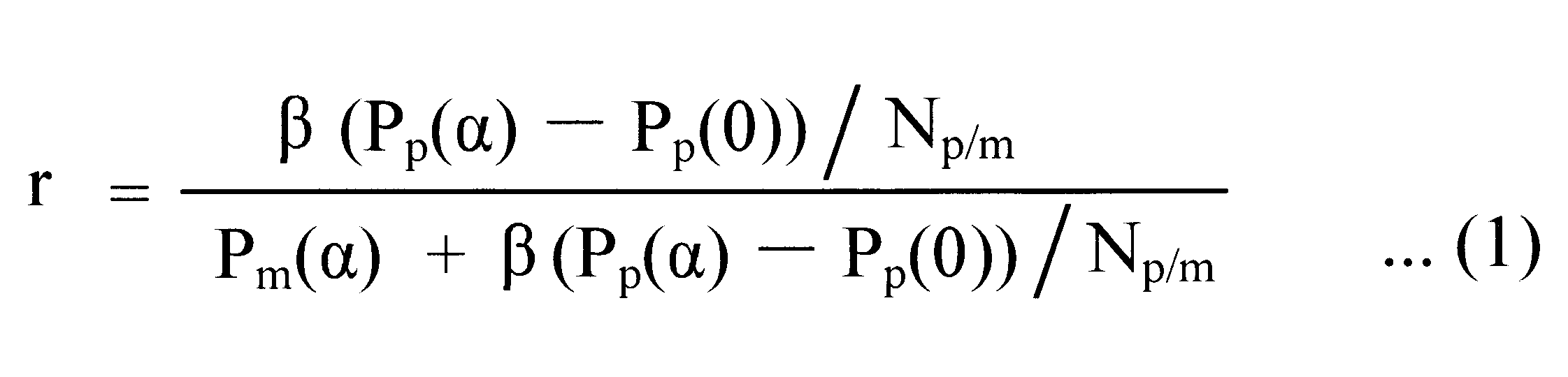
式(1)において、各パラメータの意味は以下の通りである。
Pp(α):マクロセルCmに存在してマクロ基地局100またはピコ基地局200に実際に接続する移動端末300の総数に対する、CREのオフセット値がαdBの場合にマクロセルCmにあるすべてのピコ基地局200に実際に接続するユーザ装置300の割合(つまり、マクロセルCmに存在してマクロ基地局100またはピコ基地局200に実際に接続する移動端末300の総数に対する、CREが適用される時にマクロセルCmにあるすべてのピコ基地局200と実際に接続する移動端末300の数の割合)。
Pp(0):マクロセルCmに存在してマクロ基地局100またはピコ基地局200に実際に接続する移動端末300の総数に対する、CREのオフセット値が0dBの場合にマクロセルCmにあるすべてのピコ基地局200に接続するユーザ装置300の割合(つまり、マクロセルCmに存在してマクロ基地局100またはピコ基地局200に実際に接続する移動端末300の総数に対する、CREが適用されない時にマクロセルCmにあるすべてのピコ基地局200と接続する移動端末300の数の割合)。
Pm(α):マクロセルCmに存在してマクロ基地局100またはピコ基地局200に実際に接続する移動端末300の総数に対する、CREのオフセット値がαdBの場合にマクロ基地局100に実際に接続するユーザ装置300の割合(つまり、マクロセルCmに存在してマクロ基地局100またはピコ基地局200に実際に接続する移動端末300の総数に対する、CREが適用される時にマクロ基地局100と実際に接続する移動端末300の数の割合)。
Np/m:1マクロ基地局100内のピコ基地局200の数。
β:補正係数。
CREが適用されている限り、割合Pp(α)は、マクロセルCmに存在してマクロ基地局100またはピコ基地局200に実際に接続する移動端末300の総数に対する、ピコ基地局200に実際に接続するすべての移動端末300の数の割合である。マクロ基地局100の制御部130は、当該マクロ基地局100に実際に接続する移動端末300の数Nm(α)を認識する。すなわち、マクロ基地局100の制御部130は、数Nm(α)をカウントするカウント部として機能する。また、各ピコ基地局200の制御部230は、当該ピコ基地局200に実際に接続する移動端末300の数Npi(α)を認識する。すなわち、各ピコ基地局200の制御部230は、数Npi(α)をカウントするカウント部として機能する。各ピコ基地局200の制御部230は、数Npi(α)をマクロ基地局100の制御部130に報告する。制御部130は、式(2)に従って、割合Pp(α)を計算する割合計算部として機能する。数Npi(α)の総和を求める理由は、マクロ基地局100のピコセルCpに複数のピコ基地局200が存在しうるためである。

割合Pp(0)は、マクロセルCmに存在してマクロ基地局100またはピコ基地局200に実際に接続する移動端末300の総数に対する、ピコセルCpの中央に実際にある移動端末300(CREによるピコセルCpの拡大がなくてもピコ基地局200に接続する移動端末300)の数の割合である。ピコ基地局200の制御部230は、第2受信電力値R2と閾値の比較によって、ピコセルCpの中央に実際にある移動端末300を、ピコセルCpの端部に実際にある移動端末300から識別することができる。より具体的には、ピコセルCpの中央に実際にある移動端末300とは、第2受信電力値R2が閾値より高い移動端末300であり、ピコセルCpの端部に実際にある移動端末300とは、第2受信電力値R2が閾値より低い移動端末300である。各ピコ基地局200の制御部230は、第2受信電力値R2を閾値と比較して、第2受信電力値R2が閾値より高い移動端末300と、第2受信電力値R2が閾値より低い移動端末300とを区別する移動端末分類部として機能する。また、各ピコ基地局200の制御部230は、そのピコ基地局200のピコセルCpの中央に実際にある移動端末300の数Npi(0)をカウントするカウント部として機能し、数Npi(0)をマクロ基地局100の制御部130に報告する。制御部130は、式(3)に従って、割合Pp(0)を計算する割合計算部として機能する。

第1の割合(Pp(α)-Pp(0))は、割合Pp(α)とPp(0)から計算することができる。制御部130は、このように第1の割合(Pp(α)-Pp(0))を計算する割合計算部として機能する。
但し、次のように、第1の割合(Pp(α)-Pp(0))を計算してもよい。第1の割合(Pp(α)-Pp(0))は、マクロセルCmに存在してマクロ基地局100またはピコ基地局200に実際に接続する移動端末300の総数に対する、ピコセルCpの端部に実際にある移動端末300(CREが適用されなければピコ基地局200と接続せずにマクロ基地局100に接続するであろうが、CREの適用によるピコセルCpの拡大によりピコ基地局200に接続する移動端末300)の数の割合である。ピコ基地局200の制御部230は、第2受信電力値R2と閾値の比較によって、ピコセルCpの端部にある移動端末300を、ピコセルCpの中央にある移動端末300から識別することができる。より具体的には、ピコセルCpの中央に実際にある移動端末300とは、第2受信電力値R2が閾値より高い移動端末300であり、ピコセルCpの端部に実際にある移動端末300とは、第2受信電力値R2が閾値より低い移動端末300である。各ピコ基地局200の制御部230は、第2受信電力値R2を閾値と比較して、第2受信電力値R2が閾値より高い移動端末300と、第2受信電力値R2が閾値より低い移動端末300とを区別する移動端末分類部として機能する。また、各ピコ基地局200の制御部230は、そのピコ基地局200のピコセルCpの端部に実際にある移動端末300の数Nppiをカウントするカウント部として機能し、数Nppiをマクロ基地局100の制御部130に報告してもよい。制御部130は、式(4)に従って、第1の割合(Pp(α)-Pp(0))を計算する割合計算部として機能してもよい。

CREが適用されている限り、第2の割合Pm(α)は、マクロセルCmに存在してマクロ基地局100またはピコ基地局200に実際に接続する移動端末300の総数に対する、マクロ基地局100に実際に接続するすべての移動端末300の数の割合である。制御部130は、式(5)に従って、第2の割合Pm(α)を計算する割合計算部として機能してもよい。

式(1)のパラメータである、第1の割合(Pp(α)-Pp(0))および第2の割合Pm(α)はこのようにして計算される。残りのパラメータNp/mおよびβは定数であるので、リソース設定部134は、式(1)に従って、暫定比率rを計算することができる。
式(1)において、暫定比率rは連続値となりうるが、実際のプロテクテドサブフレームPSFの割合は離散値(上記の例では、0/8,1/8,2/8,3/8,…)である。そこで、リソース設定部134は、床関数を用いた式(6)に従って、ノンプロテクテドサブフレームNSFの数とプロテクテドサブフレームPSFの数の合計数に対するプロテクテドサブフレームPSFの数の比率R(離散値)を計算する。

代わりに、リソース設定部134は、天井関数を用いた式(7)に従って、ノンプロテクテドサブフレームNSFの数とプロテクテドサブフレームPSFの数の合計数に対するプロテクテドサブフレームPSFの数の比率R(離散値)を計算してもよい。

式(6)および式(7)において、LはABSパターンの周期を表している(上記の例では8である)。このようにして、リソース設定部134は、ノンプロテクテドサブフレームNSFの数とプロテクテドサブフレームPSFの数の合計数に対するプロテクテドサブフレームPSFの数の比率R(離散値、上記の例では0/8,1/8,2/8,3/8,…)を計算することができ、比率Rに対応するABSパターンを設定する。
図9を再度参照し、上記の式(1)の技術的意義を説明する。図9から明らかなように、ノンプロテクテドサブフレームNSFは、マクロ基地局100から無線信号が送信される期間である。プロテクテドサブフレームPSFは、CREが適用されなければピコ基地局200と接続せずにマクロ基地局100に接続するであろうがCREが適用されることによりピコ基地局200に実際に接続する移動端末300(ピコセルCpの端部に実際にある移動端末300)に主に向けてピコ基地局200から無線信号が送信される期間である。接続先選択部138が設定すべき比率Rは、ノンプロテクテドサブフレームNSFの数とプロテクテドサブフレームPSFの数の合計数に対するプロテクテドサブフレームPSFの比率である。
上記のように、第2の割合Pm(α)は、マクロセルCmに存在してマクロ基地局100またはピコ基地局200に実際に接続する移動端末300の総数に対する、CREが適用される時にマクロ基地局100と実際に接続する移動端末300の数の割合である。第2の割合Pm(α)は、ノンプロテクテドサブフレームNSFに対応すると考えることができる。第1の割合(Pp(α)-Pp(0))は、マクロセルCmに存在してマクロ基地局100またはピコ基地局200に実際に接続する移動端末300の総数に対する、ピコセルCpの端部に実際にある移動端末300(CREが適用されなければピコ基地局200と接続せずにマクロ基地局100に接続するであろうが、CREの適用によるピコセルCpの拡大によりピコ基地局200に接続する移動端末300)の数の割合である。第1の割合(Pp(α)-Pp(0))は、プロテクテドサブフレームPSFに対応すると考えることができる。
したがって、暫定比率rは、式(8)に従って計算することが好ましい。
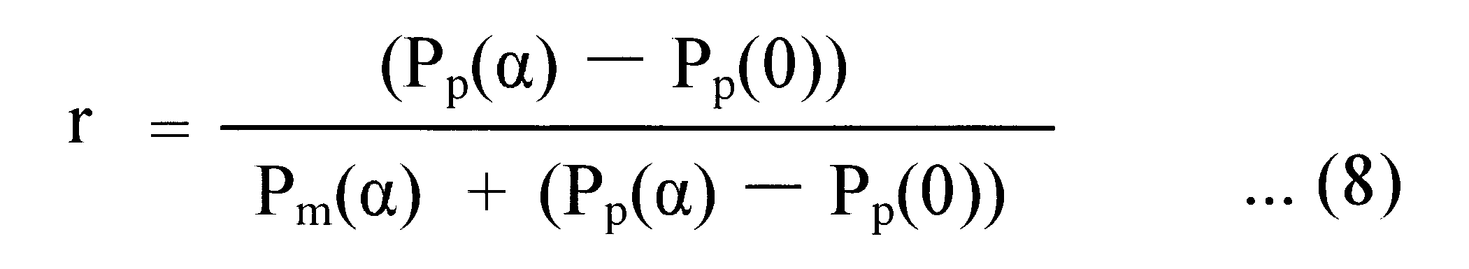
換言すれば、式(1)の補正係数βは単純には、Np/mと等しいことが好ましい。
但し、各ピコ基地局200の配置、各ピコ基地局200の周囲の電波の伝播環境、その他の要因に応じて、より適切な補正係数βを決定することができる。以上の考慮の結果、作成された好ましい式が式(1)である。
式(1)によれば、第1の割合(Pp(α)-Pp(0))に対する第2の割合Pm(α)が大きいほど、ノンプロテクテドサブフレームNSFの数とプロテクテドサブフレームPSFの数の合計数に対するプロテクテドサブフレームPSFの数の比率Rを小さく設定することができる。要するに、ピコ基地局200の端部に存在してプロテクテドサブフレームPSFを利用する移動端末300が少なく、マクロ基地局100を利用する移動端末300が多い場合には、マクロ基地局100で利用不可能な第2のリソース(プロテクテドサブフレームPSF)の量を小さく設定しマクロ基地局100で利用可能な第1のリソース(ノンプロテクテドサブフレームNSF)の量を大きく設定することができる。他方、ピコ基地局200の端部に存在してプロテクテドサブフレームPSFを利用する移動端末300が多く、マクロ基地局100を利用する移動端末300が少ない場合には、マクロ基地局100で利用不可能な第2のリソース(プロテクテドサブフレームPSF)の量を大きく設定しマクロ基地局100で利用可能な第1のリソース(ノンプロテクテドサブフレームNSF)の量を小さく設定することができる。したがって、実際の無線基地局100,200の使用状況に応じて、マクロ基地局100で利用可能なリソースの量を適切に制御することができる。移動端末300の観点から見ると、マクロ基地局100に接続する移動端末300とピコ基地局200に接続する移動端末300へのリソース割り当ての公平性が改善され、いずれの無線基地局に接続するかによってスループットが悪化することを回避することができる。
この実施の形態においては、マクロ基地局100は、そのマクロ基地局100のマクロセルCm全体に存在しマクロ基地局100と接続する移動端末300の数と、マクロセルCm全体にあるピコ基地局200に接続する移動端末300の数に基づいて、マクロセルCmで利用されるABSパターンを設定する。しかし、マクロ基地局100は、そのマクロ基地局100のマクロセルCmの1つのセクタに存在しマクロ基地局100と接続する移動端末300の数と、そのセクタにあるピコ基地局200に接続する移動端末300の数に基づいて、そのセクタで利用されるABSパターンを設定してもよい。つまり、マクロ基地局100は、マクロセルCmを構成する各セクタごとに最適なABSパターンを設定してもよい。
第2の実施の形態
次に本発明の第2の実施の形態を説明する。第2の実施の形態は、上記の第1の実施の形態と、マクロ基地局100のリソース設定部134による比率Rの設定の手法が異なる。第2の実施の形態において、マクロ基地局100、ピコ基地局200、および移動端末300の構成は、第1の実施の形態のそれらと同じでよい。第1の実施の形態と共通する特徴については詳細には説明しない。
次に本発明の第2の実施の形態を説明する。第2の実施の形態は、上記の第1の実施の形態と、マクロ基地局100のリソース設定部134による比率Rの設定の手法が異なる。第2の実施の形態において、マクロ基地局100、ピコ基地局200、および移動端末300の構成は、第1の実施の形態のそれらと同じでよい。第1の実施の形態と共通する特徴については詳細には説明しない。
第2の実施の形態のマクロ基地局100のリソース設定部134は、CREが適用されなければピコ基地局200と接続せずにマクロ基地局100に接続するであろうがCREが適用されることによりピコ基地局200に実際に接続する移動端末300の数である第1の数(Np(α)-Np(0))、およびCREが適用される時にマクロ基地局100と実際に接続する移動端末300の数である第2の数Nm(α)に基づいて、第1の数(Np(α)-Np(0))に対する第2の数Nm(α)が大きいほど、ノンプロテクテドサブフレームNSFの数とプロテクテドサブフレームPSFの数の合計数に対するプロテクテドサブフレームPSFの数の比率Rを小さく設定する。
具体的な比率の設定の例を説明する。マクロ基地局10のリソース設定部134は、式(9)に従って、当該マクロ基地局100における、ノンプロテクテドサブフレームNSFの数とプロテクテドサブフレームPSFの数の合計数に対するプロテクテドサブフレームPSFの暫定比率rを計算する。

式(9)において、各パラメータの意味は以下の通りである。
Np(α):CREのオフセット値がαdBの場合にマクロ基地局100のマクロセルCmにあるすべてのピコ基地局200に実際に接続するユーザ装置300の数(つまり、CREが適用される時にマクロセルCmにあるすべてのピコ基地局200と実際に接続する移動端末300の数)。
Np(0):CREのオフセット値が0dBの場合にマクロ基地局100のマクロセルCmにあるすべてのピコ基地局200に接続するユーザ装置300の数(つまり、CREが適用されない時にマクロセルCmにあるすべてのピコ基地局200と接続する移動端末300の数)。
Nm(α):CREのオフセット値がαdBの場合にマクロ基地局100に実際に接続するユーザ装置300の数(つまり、CREが適用される時にマクロ基地局100と実際に接続する移動端末300の数)。
Np/m:1マクロ基地局100内のピコ基地局200の数。
β:補正係数。
CREが適用されている限り、第2の数Nm(α)は、マクロ基地局100に実際に接続するすべての移動端末300の数である。マクロ基地局100の制御部130は、当該マクロ基地局100に実際に接続する移動端末300の数Nm(α)を認識する。すなわち、マクロ基地局100の制御部130は、数Nm(α)をカウントするカウント部として機能する。
CREが適用されている限り、数Np(α)は、ピコ基地局200に実際に接続するすべての移動端末300の数である。各ピコ基地局200の制御部230は、当該ピコ基地局200に実際に接続する移動端末300の数Npi(α)を認識する。すなわち、各ピコ基地局200の制御部230は、数Npi(α)をカウントするカウント部として機能する。各ピコ基地局200の制御部230は、数Npi(α)をマクロ基地局100の制御部130に報告する。制御部130は、式(10)に従って、数Np(α)を計算する数計算部として機能する。

数Np(0)は、ピコセルCpの中央に実際にある移動端末300(CREによるピコセルCpの拡大がなくてもピコ基地局200に接続する移動端末300)の数である。ピコ基地局200の制御部230は、第2受信電力値R2と閾値の比較によって、ピコセルCpの中央に実際にある移動端末300を、ピコセルCpの端部に実際にある移動端末300から識別することができる。より具体的には、ピコセルCpの中央に実際にある移動端末300とは、第2受信電力値R2が閾値より高い移動端末300であり、ピコセルCpの端部に実際にある移動端末300とは、第2受信電力値R2が閾値より低い移動端末300である。各ピコ基地局200の制御部230は、第2受信電力値R2を閾値と比較して、第2受信電力値R2が閾値より高い移動端末300と、第2受信電力値R2が閾値より低い移動端末300とを区別する移動端末分類部として機能する。また、各ピコ基地局200の制御部230は、そのピコ基地局200のピコセルCpの中央に実際にある移動端末300の数Npi(0)をカウントするカウント部として機能し、数Npi(0)をマクロ基地局100の制御部130に報告する。制御部130は、式(11)に従って、数Np(0)を計算する数計算部として機能する。

第1の数(Np(α)-Np(0))は、数Np(α)とNp(0)から計算することができる。制御部130は、このように第1の数(Np(α)-Np(0))を計算する数計算部として機能する。
但し、次のように、第1の数(Np(α)-Np(0))を計算してもよい。第1の数(Np(α)-Np(0))は、ピコセルCpの端部に実際にある移動端末300(CREが適用されなければピコ基地局200と接続せずにマクロ基地局100に接続するであろうが、CREの適用によるピコセルCpの拡大によりピコ基地局200に接続する移動端末300)の数である。ピコ基地局200の制御部230は、第2受信電力値R2と閾値の比較によって、ピコセルCpの端部にある移動端末300を、ピコセルCpの中央にある移動端末300から識別することができる。より具体的には、ピコセルCpの中央に実際にある移動端末300とは、第2受信電力値R2が閾値より高い移動端末300であり、ピコセルCpの端部に実際にある移動端末300とは、第2受信電力値R2が閾値より低い移動端末300である。各ピコ基地局200の制御部230は、第2受信電力値R2を閾値と比較して、第2受信電力値R2が閾値より高い移動端末300と、第2受信電力値R2が閾値より低い移動端末300とを区別する移動端末分類部として機能する。また、各ピコ基地局200の制御部230は、そのピコ基地局200のピコセルCpの端部に実際にある移動端末300の数Nppiをカウントするカウント部として機能し、数Nppiをマクロ基地局100の制御部130に報告してもよい。制御部130は、式(12)に従って、第1の数(Np(α)-Np(0))を計算する数計算部として機能してもよい。
式(9)のパラメータである、第1の数(Np(α)-Np(0))および第2の数Nm(α)はこのようにして計算される。残りのパラメータNp/mおよびβは定数であるので、リソース設定部134は、式(9)に従って、暫定比率rを計算することができる。
式(9)において、暫定比率rは連続値となりうるが、実際のプロテクテドサブフレームPSFの割合は離散値(上記の例では、0/8,1/8,2/8,3/8,…)である。そこで、リソース設定部134は、床関数を用いた上記の式(6)に従って、ノンプロテクテドサブフレームNSFの数とプロテクテドサブフレームPSFの数の合計数に対するプロテクテドサブフレームPSFの数の比率R(離散値)を計算する。代わりに、リソース設定部134は、天井関数を用いた上記の式(7)に従って、ノンプロテクテドサブフレームNSFの数とプロテクテドサブフレームPSFの数の合計数に対するプロテクテドサブフレームPSFの数の比率R(離散値)を計算してもよい。このようにして、リソース設定部134は、ノンプロテクテドサブフレームNSFの数とプロテクテドサブフレームPSFの数の合計数に対するプロテクテドサブフレームPSFの数の比率R(離散値、上記の例では0/8,1/8,2/8,3/8,…)を計算することができ、比率Rに対応するABSパターンを設定する。
式(2)~(5)、(8)~(12)に鑑みて、式(9)は実は式(1)と完全に等価である。図9を再度参照し、上記の式(9)の技術的意義を説明する。図9から明らかなように、ノンプロテクテドサブフレームNSFは、マクロ基地局100から無線信号が送信される期間である。プロテクテドサブフレームPSFは、CREが適用されなければピコ基地局200と接続せずにマクロ基地局100に接続するであろうがCREが適用されることによりピコ基地局200に実際に接続する移動端末300(ピコセルCpの端部に実際にある移動端末300)に主に向けてピコ基地局200から無線信号が送信される期間である。接続先選択部138が設定すべき比率Rは、ノンプロテクテドサブフレームNSFの数とプロテクテドサブフレームPSFの数の合計数に対するプロテクテドサブフレームPSFの比率である。
上記のように、第2の数Nm(α)は、CREが適用される時にマクロ基地局100と実際に接続する移動端末300の数である。第2の数Nm(α)は、ノンプロテクテドサブフレームNSFに対応すると考えることができる。第1の数(Np(α)-Np(0))は、ピコセルCpの端部に実際にある移動端末300(CREが適用されなければピコ基地局200と接続せずにマクロ基地局100に接続するであろうが、CREの適用によるピコセルCpの拡大によりピコ基地局200に接続する移動端末300)の数である。第1の数(Np(α)-Np(0))は、プロテクテドサブフレームPSFに対応すると考えることができる。
したがって、暫定比率rは、式(13)に従って計算することが好ましい。
換言すれば、式(9)の補正係数βは単純には、Np/mと等しいことが好ましい。
但し、各ピコ基地局200の配置、各ピコ基地局200の周囲の電波の伝播環境、その他の要因に応じて、より適切な補正係数βを決定することができる。以上の考慮の結果、作成された好ましい式が式(9)である。
式(9)によれば、第1の数(Np(α)-Np(0))に対する第2の数Nm(α)が大きいほど、ノンプロテクテドサブフレームNSFの数とプロテクテドサブフレームPSFの数の合計数に対するプロテクテドサブフレームPSFの数の比率Rを小さく設定することができる。要するに、ピコ基地局200の端部に存在してプロテクテドサブフレームPSFを利用する移動端末300が少なく、マクロ基地局100を利用する移動端末300が多い場合には、マクロ基地局100で利用不可能な第2のリソース(プロテクテドサブフレームPSF)の量を小さく設定しマクロ基地局100で利用可能な第1のリソース(ノンプロテクテドサブフレームNSF)の量を大きく設定することができる。他方、ピコ基地局200の端部に存在してプロテクテドサブフレームPSFを利用する移動端末300が多く、マクロ基地局100を利用する移動端末300が少ない場合には、マクロ基地局100で利用不可能な第2のリソース(プロテクテドサブフレームPSF)の量を大きく設定しマクロ基地局100で利用可能な第1のリソース(ノンプロテクテドサブフレームNSF)の量を小さく設定することができる。したがって、実際の無線基地局100,200の使用状況に応じて、マクロ基地局100で利用可能なリソースの量を適切に制御することができる。移動端末300の観点から見ると、マクロ基地局100に接続する移動端末300とピコ基地局200に接続する移動端末300へのリソース割り当ての公平性が改善され、いずれの無線基地局に接続するかによってスループットが悪化することを回避することができる。
この実施の形態においては、マクロ基地局100は、そのマクロ基地局100のマクロセルCm全体に存在しマクロ基地局100と接続する移動端末300の数と、マクロセルCm全体にあるピコ基地局200に接続する移動端末300の数に基づいて、マクロセルCmで利用されるABSパターンを設定する。しかし、マクロ基地局100は、そのマクロ基地局100のマクロセルCmの1つのセクタに存在しマクロ基地局100と接続する移動端末300の数と、そのセクタにあるピコ基地局200に接続する移動端末300の数に基づいて、そのセクタで利用されるABSパターンを設定してもよい。つまり、マクロ基地局100は、マクロセルCmを構成する各セクタごとに最適なABSパターンを設定してもよい。
第3の実施の形態
次に本発明の第3の実施の形態を説明する。第3の実施の形態は、第1の実施の形態の変形である。第3の実施の形態において、マクロ基地局100、ピコ基地局200、および移動端末300の構成は、第1の実施の形態のそれらと同じでよい。第1の実施の形態と共通する特徴については詳細には説明しない。
次に本発明の第3の実施の形態を説明する。第3の実施の形態は、第1の実施の形態の変形である。第3の実施の形態において、マクロ基地局100、ピコ基地局200、および移動端末300の構成は、第1の実施の形態のそれらと同じでよい。第1の実施の形態と共通する特徴については詳細には説明しない。
第1の実施の形態の特徴に加えて、第3の実施の形態では、マクロ基地局100のリソース設定部134は、マクロ基地局100でのリソースの実際の使用率に基づいて、使用率が小さいほど、ノンプロテクテドサブフレームNSFの数とプロテクテドサブフレームPSFの数の合計数に対するプロテクテドサブフレームPSFの数の比率Rを小さく設定する。
具体的な比率の設定の例を説明する。マクロ基地局10のリソース設定部134は、式(14)に従って、当該マクロ基地局100における、ノンプロテクテドサブフレームNSFの数とプロテクテドサブフレームPSFの数の合計数に対するプロテクテドサブフレームPSFの暫定比率rを計算する。
式(14)において、Um以外の各パラメータの意味は式(1)に関連して上記した。第1の割合(Pp(α)-Pp(0))および第2の割合Pm(α)は、第1の実施の形態に関連して上記した手法で計算することができる。式(9)の補正係数βは単純には、Np/mと等しいことが好ましいが、各ピコ基地局200の配置、各ピコ基地局200の周囲の電波の伝播環境、その他の要因に応じて、より適切な補正係数βを決定することができる。
パラメータUmは、マクロ基地局100でのリソースの実際の使用率である。上記の通り、マクロ基地局100には、マクロ基地局100に接続する移動端末300への無線送信のために、ノンプロテクテドサブフレームNSFが割り当てられる。LTEにおいて、各サブフレームは、さらに小さい送信単位である複数のリソースエレメント(周波数および時間で特定される)に区分される。マクロ基地局100に接続する移動端末300への下りリンクの無線送信のために、マクロ基地局100は、これらのリソースエレメントを各移動端末300宛の信号に割り当てるスケジューリングを実行する。使用率Umは、ノンプロテクテドサブフレームNSFを構成するすべてのリソースエレメントの数に対する、実際にマクロ基地局100において各移動端末300宛の信号に割り当てられるリソースエレメントの数の比率である。
使用率Umは、瞬間的な現在の使用率でもよいし、過去に計算されたいくつかの使用率の平均値または中央値でもよいし、過去に計算されたいくつかの使用率と現在の使用率の平均値または中央値でもよい。いずれにせよ、マクロ基地局100の制御部130は、ノンプロテクテドサブフレームNSFを構成するすべてのリソースエレメントの数に対する、実際に各移動端末300宛の信号に割り当てられるリソースエレメントの数の比率である使用率Umを計算する、使用率計算部として機能する。
リソース設定部134は、式(14)に従って、暫定比率rを計算することができる。式(14)において、暫定比率rは連続値となりうるが、実際のプロテクテドサブフレームPSFの割合は離散値(上記の例では、0/8,1/8,2/8,3/8,…)である。そこで、リソース設定部134は、床関数を用いた上記の式(6)に従って、ノンプロテクテドサブフレームNSFの数とプロテクテドサブフレームPSFの数の合計数に対するプロテクテドサブフレームPSFの数の比率R(離散値)を計算する。代わりに、リソース設定部134は、天井関数を用いた上記の式(7)に従って、ノンプロテクテドサブフレームNSFの数とプロテクテドサブフレームPSFの数の合計数に対するプロテクテドサブフレームPSFの数の比率R(離散値)を計算してもよい。このようにして、リソース設定部134は、ノンプロテクテドサブフレームNSFの数とプロテクテドサブフレームPSFの数の合計数に対するプロテクテドサブフレームPSFの数の比率R(離散値、上記の例では0/8,1/8,2/8,3/8,…)を計算することができ、比率Rに対応するABSパターンを設定する。
したがって、マクロ基地局100でのリソースの実際の使用率Umが小さいほど、ノンプロテクテドサブフレームNSFの数とプロテクテドサブフレームPSFの数の合計数に対するプロテクテドサブフレームPSFの数の比率Rを小さく設定することができる。このように、式(14)において、マクロ基地局100のリソース使用率Umを乗算している理由は、以下の通りである。
この実施の形態では、マクロ基地局100でのリソースの使用率Umが低い場合、あえて、プロテクテドサブフレームPSFの比率Rを低く(マクロ基地局100で使用されるノンプロテクテドサブフレームNSFの比率を上げる)することにより、マクロ基地局100からの下りリンクのトラヒックを早く送信することができる。マクロ基地局100からの下りリンクのトラヒックの送信終了後は、ピコ基地局200に接続する移動端末300に対して、プロテクテドサブフレームPSFにおいてもノンプロテクテドサブフレームNSFにおいてもマクロ基地局100からの電波による干渉はなくなる。つまり、ABSパターンの各周期(上記の例では8である)においてマクロ基地局100からの下りリンクのトラヒックの送信終了後は、ピコ基地局200に接続する移動端末300にとって、ノンプロテクテドサブフレームNSFは、プロテクテドサブフレームPSFと等価であり、ピコ基地局200から移動端末300への距離に関わらず(移動端末300の第2受信電力値R2の大小に関わらず)、ピコ基地局200はノンプロテクテドサブフレームNSFをどの移動端末300への無線送信にも利用することができる。結果的に、ABSパターンの各周期において、マクロ基地局100からの下りリンクのトラヒックの送信終了後は、ピコ基地局200からの下りリンクのトラヒックを早く送信することができる(ピコ基地局200のスループットを上げることができる)。
以上、第1の実施の形態の変形である第3の実施の形態を説明したが、同様の考え方を当て嵌めて第2の実施の形態を変形してもよい。つまり、マクロ基地局10のリソース設定部134は、式(15)に従って、当該マクロ基地局100における、ノンプロテクテドサブフレームNSFの数とプロテクテドサブフレームPSFの数の合計数に対するプロテクテドサブフレームPSFの暫定比率rを計算してもよい。
式(15)において、Um以外の各パラメータの意味は式(9)に関連して上記した。第1の数(Np(α)-Np(0))および第2の数Nm(α)は、第2の実施の形態に関連して上記した手法で計算することができる。式(15)の補正係数βは単純には、Np/mと等しいことが好ましいが、各ピコ基地局200の配置、各ピコ基地局200の周囲の電波の伝播環境、その他の要因に応じて、より適切な補正係数βを決定することができる。
リソース設定部134は、床関数を用いた上記の式(6)または天井関数を用いた上記の式(7)に従って、ノンプロテクテドサブフレームNSFの数とプロテクテドサブフレームPSFの数の合計数に対するプロテクテドサブフレームPSFの数の比率R(離散値)を計算してよい。このようにして、マクロ基地局100のリソース設定部134は、マクロ基地局100でのリソースの使用率Umに基づいて、使用率Umが小さいほど、ノンプロテクテドサブフレームNSFの数とプロテクテドサブフレームPSFの数の合計数に対するプロテクテドサブフレームPSFの数の比率Rを小さく設定することができる。
第4の実施の形態
第1~第3の実施の形態では、マクロ基地局100のリソース設定部134が決定した比率Rおよびそれに対応するABSパターンがそのまま使用される。すなわち、このABSパターンに対応するリソース配分情報ALに基づいて、マクロ基地局100の通信制御部136は無線通信部110を制御する。そのマクロ基地局100のマクロセルCm内にあるピコ基地局200の制御部230は、例えばプロポーショナルフェアネスアルゴリズムに従って、そのピコ基地局200と接続する移動端末300への下りリンクのリソース配分、すなわちスケジューリングを行い、無線通信部210を制御する。ピコ基地局200の制御部230は、リソース配分情報ALに基づいて、無線通信部210を制御してもよい。
第1~第3の実施の形態では、マクロ基地局100のリソース設定部134が決定した比率Rおよびそれに対応するABSパターンがそのまま使用される。すなわち、このABSパターンに対応するリソース配分情報ALに基づいて、マクロ基地局100の通信制御部136は無線通信部110を制御する。そのマクロ基地局100のマクロセルCm内にあるピコ基地局200の制御部230は、例えばプロポーショナルフェアネスアルゴリズムに従って、そのピコ基地局200と接続する移動端末300への下りリンクのリソース配分、すなわちスケジューリングを行い、無線通信部210を制御する。ピコ基地局200の制御部230は、リソース配分情報ALに基づいて、無線通信部210を制御してもよい。
しかし、以下の様々な実施の形態のように、マクロ基地局100は、そのマクロ基地局100で一旦決定された比率Rを、そのマクロ基地局100の周辺にある他のマクロ基地局100で過去に一旦決定された比率Rに基づいて補正し、補正済み比率ARに対応するABSパターンを使用してもよい。
本発明の第4の実施の形態を説明する。第4の実施の形態および後続の実施の形態において、マクロ基地局100、ピコ基地局200、および移動端末300の構成は、第1の実施の形態のそれらと同じでよい。第1の実施の形態と共通する特徴については詳細には説明しない。マクロ基地局100のリソース設定部134は、第1~第3の実施の形態の手法で、ノンプロテクテドサブフレームNSFの数とプロテクテドサブフレームPSFの数の合計数に対するプロテクテドサブフレームPSFの数の比率Rを一旦決定し、さらに比率Rに対応するABSパターンを一旦決定する。
図10は、本発明に係る無線通信システムでの複数のマクロ基地局100、複数のピコ基地局200および複数のマクロセルCmの配置の例を示す略図である。各マクロ基地局100が形成するマクロセルCmには、少なくとも1つのピコ基地局200が配置されている。図10では、複数のマクロセルCmが重なっていないが、当然ながらマクロセルCmは互いに重なっていてよい。
第4の実施の形態および後続の実施の形態において、いくつかのピコ基地局200の各々は、隣り合う2つのマクロ基地局100と通信するように構成された共通ピコ基地局(共通小電力無線基地局)であり、複数のマクロ基地局100(図10に示すマクロ基地局1000~1008)の各々は、複数の共通ピコ基地局200と通信するように構成されている。例えば、図10において、ピコ基地局20001は、隣り合う2つのマクロ基地局1000,1001にとって共通ピコ基地局であり、ピコ基地局20002は、隣り合う2つのマクロ基地局1000,1002にとって共通ピコ基地局である。
各マクロ基地局100のリソース設定部134は所定の制御周期ごとに比率RおよびABSパターンを一旦決定する。各共通ピコ基地局200は、そのピコ基地局200を共用する隣り合う2つのマクロ基地局100(便宜的に第1のマクロ基地局100および第2のマクロ基地局100と呼ぶ)で一旦決定された比率Rのうちの最小値を選択し、選択された最小値を第1のマクロ基地局100および第2のマクロ基地局100に報告する。各マクロ基地局100は、周辺にある複数の共通ピコ基地局200のそれぞれから複数の最小値を受信する。例えば、図10において、マクロ基地局1000は、ピコ基地局20001,20002だけでなく、マクロ基地局1000,1003の共通ピコ基地局、マクロ基地局1000,1004の共通ピコ基地局、マクロ基地局1000,1005の共通ピコ基地局、およびマクロ基地局1000,1006の共通ピコ基地局から最小値を受信する。マクロ基地局1001は、ピコ基地局20001だけでなく、マクロ基地局1001,1006の共通ピコ基地局、マクロ基地局1001,1007の共通ピコ基地局、マクロ基地局1001,1008の共通ピコ基地局、マクロ基地局1001,1009の共通ピコ基地局、およびマクロ基地局1001,1002の共通ピコ基地局から最小値を受信する。
各マクロ基地局100のリソース設定部134は、リソース設定部134で現在決定された比率Rと、ピコ基地局200から受信された一制御周期前の複数の最小値とのうちの最小値を、そのマクロ基地局100の通信制御部136が従うべき補正済み比率として採用する。
図11は、第4の実施の形態での無線通信システムの動作を示す。説明の便宜上、図11には、マクロ基地局1000~1002およびピコ基地局20001,20002のみを示す。しかし、他のマクロ基地局および共通ピコ基地局も同様に動作する。図11に示すように、各マクロ基地局100のリソース設定部134は、比率RおよびABSパターンを一旦決定する。リソース設定部134は、決定したABSパターンを基地局間通信部120によって共通ピコ基地局に報告する。ABSパターンは比率Rに対応しているので、マクロ基地局100が送信するABSパターンを示す信号は、比率Rを示す信号である。
隣り合う2つのマクロ基地局100から2つのABSパターンの報告を基地局間通信部220でそれぞれ受信すると、各共通ピコ基地局200の制御部(最小値選択部)230は、2つのABSパターンからコモンセットを決定する。図12は比率Rが1/8の場合のABSパターンを示し、図13は比率Rが3/8の場合のABSパターンを示す。プロテクテドサブフレームPSFの比率Rがより高いABSパターンのプロテクテドサブフレームPSFは、プロテクテドサブフレームPSFの比率Rがより低いABSパターンのプロテクテドサブフレームPSFを必ず含む。つまり比率Rがn/8のABSパターンのプロテクテドサブフレームPSFは、比率Rが(n-1)/8の場合のABSパターンのプロテクテドサブフレームPSFを必ず含む。例えば、比率3/8のABSパターン(図13)でのプロテクテドサブフレームPSFは、比率1/8のABSパターン(図12)に出現する8サブフレーム単位の末尾のプロテクテドサブフレームPSFを含む。
コモンセットとは、2つのABSパターンのうちプロテクテドサブフレームPSFが共通するABSパターンである。換言すれば、2つのABSパターンのうち、対応する比率Rが最小である1つのABSパターンである。例えば、比率Rが1/8の場合のABSパターン(図12)と比率Rが3/8の場合のABSパターン(図13)のコモンセットは、比率Rが1/8の場合のABSパターンである。したがって、各共通ピコ基地局200の制御部(最小値選択部)230がコモンセットを決定または選択することは、その共通ピコ基地局200が関連する2つのマクロ基地局100のリソース設定部134で一旦決定された比率の最小値を選択することと等価である。
図11に戻り、制御部230がコモンセットを選択すると、共通ピコ基地局200の制御部(最小値報告部)230は、基地局間通信部220によってそのピコ基地局200が関連するマクロ基地局100にコモンセット(ひいては最小値)を報告する。各マクロ基地局100の基地局間通信部(最小値受信部)120は、そのマクロ基地局100が関連する複数の共通ピコ基地局200のそれぞれから複数のコモンセット(ひいては最小値)を受信する。
次の制御時点で、各マクロ基地局100のリソース設定部134は比率RおよびABSパターンを一旦決定する。すると、マクロ基地局100のリソース設定部134は、現在決定された比率Rと、基地局間通信部120で受信された複数のコモンセット(ひいては最小値)に基づいて、ABSパターンを最終決定する。
第4の実施の形態のABSパターンの最終決定において、リソース設定部134は、そのリソース設定部134で現在決定されたABSパターンと、基地局間通信部120で受信された複数のコモンセット(現在決定されたABSパターンにとって一制御周期前のコモンセットである)のコモンセットを選択する。この選択は、そのリソース設定部134で現在決定された比率R(t)と、基地局間通信部120で受信された一制御周期前の複数の最小値R(t-1)とのうちの最小値を選択することと等価である。そして、リソース設定部134は、この最小値(リソース設定部134で選択されたコモンセット、即ちABSパターンに対応する比率R)をマクロ基地局100の通信制御部136が従うべき補正済み比率ARとして採用すなわち設定する。
この補正済み比率ARに対応するABSパターンに対応するリソース配分情報ALに基づいて、マクロ基地局100の通信制御部136は無線通信部110を制御する。そのマクロ基地局100のマクロセルCm内にあるピコ基地局200の制御部230は、例えばプロポーショナルフェアネスアルゴリズムに従って、そのピコ基地局200と接続する移動端末300への下りリンクのリソース配分、すなわちスケジューリングを行い、無線通信部210を制御する。ピコ基地局200の制御部200は、リソース配分情報ALに基づいて、無線通信部210を制御してもよい。他方、リソース設定部134は、一旦決定した現在のABSパターン(現在の比率R)を基地局間通信部120によって共通ピコ基地局に報告する。以降、上記と同様の動作が繰り返される。
図14を参照して、この実施の形態によるマクロ基地局1000(図10参照)で最終的に設定される補正済み比率ARの例を説明する。マクロ基地局1000で一制御周期前に一旦決定された比率R0(t-1)が4/8であると想定する。同様に、マクロ基地局1001で一制御周期前に一旦決定された比率R1(t-1)が3/8であり、マクロ基地局1002で一制御周期前に一旦決定された比率R2(t-1)が2/8であると想定する。比率R3(t-1)が3/8であり、比率R4(t-1)が2/8であり、比率R5(t-1)が3/8であり、比率R6(t-1)が3/8であると想定される。
マクロ基地局1000には、マクロ基地局1000に関連する複数の共通ピコ基地局200から複数のコモンセットを示す情報が送信される。これらのコモンセットは、2/8,3/8,2/8,3/8,3/8,3/8である。これらのコモンセットのうち最小の比率R(t-1)は2/8である。マクロ基地局1000のリソース設定部134は、現在の比率R0(t)を4/8と一旦決定すると想定する。マクロ基地局1000のリソース設定部134は、現在の比率R0(t)と複数のコモンセットが示す比率のうち最小値を選択するので、リソース設定部134は、補正済み比率ARを2/8と最終的に決定する。
以上のように、第4の実施の形態においては、各マクロ基地局100は、周辺にある他のマクロ基地局100で一制御周期前に一旦決定された比率R(t-1)に基づくコモンセットに対応する比率と、当該マクロ基地局100で現在決定された比率R(t)のうちの最小値をマクロ基地局100の通信制御部136が従うべき補正済み比率ARとして採用すなわち設定する。
これに対して、第1~第3の実施の形態では、マクロ基地局100のリソース設定部134が決定した比率Rがマクロ基地局100の通信制御部136が従うべき比率として採用される。この場合、大きい方の比率Rが使用されるマクロセルCmでのプロテクテドサブフレームPSFの一部は、小さい方の比率Rが使用されるマクロセルCmでのプロテクテドサブフレームPSFと一致しない(そのサブフレームはマクロ基地局100が無線送信するノンプロテクテドサブフレームNSFである)。したがって、隣り合う複数のマクロ基地局100が異なる比率R(異なるABSパターン)を使用する場合、大きい方の比率Rが使用されるマクロセルCm内のピコ基地局200と通信する移動端末300にとっては、そのマクロセルCm内のプロテクテドサブフレームPSFで信号を受信していても、周辺のマクロセルCmのマクロ基地局100が送信する信号により干渉を受けるおそれがある。特に、隣り合う複数のマクロ基地局100での比率Rの相違が大きい場合には、この懸念が大きい。
第4の実施の形態では、隣り合うマクロ基地局100で使用される比率(補正済み比率AR)の相違を小さくすることができ、上記の他のマクロ基地局100に起因する干渉の問題を低減または防止することができる。
第5の実施の形態
第4の実施の形態では、共通ピコ基地局200の仲介によって、各マクロ基地局100は、周辺にある他のマクロ基地局100で一制御周期前に一旦決定された比率R(t-1)に基づくコモンセットに対応する比率と、当該マクロ基地局100で現在決定された比率R(t)のうちの最小値をマクロ基地局100の通信制御部136が従うべき補正済み比率ARとして採用すなわち設定する。
第4の実施の形態では、共通ピコ基地局200の仲介によって、各マクロ基地局100は、周辺にある他のマクロ基地局100で一制御周期前に一旦決定された比率R(t-1)に基づくコモンセットに対応する比率と、当該マクロ基地局100で現在決定された比率R(t)のうちの最小値をマクロ基地局100の通信制御部136が従うべき補正済み比率ARとして採用すなわち設定する。
しかし、共通ピコ基地局200の仲介なしで、マクロ基地局100の相互の通信によって、各マクロ基地局100は、周辺にある他のマクロ基地局100で一制御周期前に一旦決定された比率R(t-1)と、当該マクロ基地局100で現在決定された比率R(t)のうちの最小値をマクロ基地局100の通信制御部136が従うべき補正済み比率ARとして採用すなわち設定してもよい。このような実施の形態である第5の実施の形態を説明する。
第5の実施の形態においても、マクロ基地局100のリソース設定部134は、第1~第3の実施の形態の手法で、ノンプロテクテドサブフレームNSFの数とプロテクテドサブフレームPSFの数の合計数に対するプロテクテドサブフレームPSFの数の比率Rを一旦決定し、さらに比率Rに対応するABSパターンを一旦決定する。複数のマクロ基地局100の各々のリソース設定部134は、リソース設定部134で現在決定された比率R(t)と、このリソース設定部134が設けられた当該マクロ基地局100の周辺にある周辺マクロ基地局100のリソース設定部134で過去に決定された比率R(t-1)とのうちの最小値を選択し、選択された最小値を当該マクロ基地局100の通信制御部136が従うべき補正済み比率ARとして採用する。
図15は、第5の実施の形態での無線通信システムの動作を示す。説明の便宜上、図15には、マクロ基地局1000~1002のみを示す。しかし、他のマクロ基地局も同様に動作する。図15に示すように、各マクロ基地局100のリソース設定部134は、比率RおよびABSパターンを一旦決定する。リソース設定部134は、決定したABSパターンを基地局間通信部120によって周辺マクロ基地局に報告する。ABSパターンは比率Rに対応しているので、マクロ基地局100が送信するABSパターンを示す信号は、比率Rを示す信号である。
次の制御時点で、各マクロ基地局100のリソース設定部134は比率RおよびABSパターンを一旦決定する。すると、マクロ基地局100のリソース設定部134は、現在決定された比率R(t)と、基地局間通信部120で受信された複数の周辺マクロ基地局からの複数のABSパターン(ひいては比率R(t-1)に基づいて、ABSパターンを最終決定する。
第5の実施の形態のABSパターンの最終決定において、リソース設定部134は、そのリソース設定部134で現在決定されたABSパターンと、基地局間通信部120で受信された複数のABSパターン(現在決定されたABSパターンにとって一制御周期前のABSパターンである)のコモンセットを選択する。この選択は、そのリソース設定部134で現在決定された比率R(t)と、基地局間通信部120で受信された一制御周期前の複数の比率R(t-1)とのうちの最小値を選択することと等価である。そして、リソース設定部134は、この最小値(リソース設定部134で選択されたコモンセット、即ちABSパターンに対応する比率R)をマクロ基地局100の通信制御部136が従うべき補正済み比率ARとして採用すなわち設定する。
この補正済み比率ARに対応するABSパターンに対応するリソース配分情報ALに基づいて、マクロ基地局100の通信制御部136は無線通信部110を制御する。そのマクロ基地局100のマクロセルCm内にあるピコ基地局200の制御部230は、例えばプロポーショナルフェアネスアルゴリズムに従って、そのピコ基地局200と接続する移動端末300への下りリンクのリソース配分、すなわちスケジューリングを行い、無線通信部210を制御する。ピコ基地局200の制御部230は、リソース配分情報ALに基づいて、無線通信部210を制御してもよい。他方、リソース設定部134は、一旦決定した現在のABSパターン(現在の比率R)を基地局間通信部120によって周辺マクロ基地局に報告する。以降、上記と同様の動作が繰り返される。
この実施の形態においても、例えば図14を参照して上記した状況においては、マクロ基地局1000のリソース設定部134は、現在の比率R0(t)と複数の比率R1(t-1)~R6(t-1)のうち最小値を選択するので、リソース設定部134は、補正済み比率ARを2/8と最終的に決定する。
以上のように、第5の実施の形態においては、各マクロ基地局100は、周辺にある他のマクロ基地局100で一制御周期前に一旦決定された比率R(t-1)と、当該マクロ基地局100で現在決定された比率R(t)のうちの最小値をマクロ基地局100の通信制御部136が従うべき補正済み比率ARとして採用すなわち設定する。したがって、隣り合うマクロ基地局100で使用される比率(補正済み比率AR)の相違を小さくすることができ、上記の他のマクロ基地局100に起因する干渉の問題を低減または防止することができる。この実施の形態では、ピコ基地局200は共通ピコ基地局として動作することを要しない。
第6の実施の形態
第4の実施の形態では、各マクロ基地局100のリソース設定部134は、そのマクロ基地局100のリソース設定部134で現在決定された比率と、基地局間通信部(最小値受信部)120で受信された一周期前の複数の最小値とのうちの最小値を、そのマクロ基地局100の通信制御部136が従うべき補正済み比率ARとして採用する。
第4の実施の形態では、各マクロ基地局100のリソース設定部134は、そのマクロ基地局100のリソース設定部134で現在決定された比率と、基地局間通信部(最小値受信部)120で受信された一周期前の複数の最小値とのうちの最小値を、そのマクロ基地局100の通信制御部136が従うべき補正済み比率ARとして採用する。
しかし、各マクロ基地局100のリソース設定部134は、そのマクロ基地局100のリソース設定部134で現在決定された比率と、基地局間通信部(最小値受信部)120で受信された一周期前の複数の最小値の平均値または中央値を、そのマクロ基地局100の通信制御部136が従うべき補正済み比率ARとして採用してもよい。このような実施の形態である第6の実施の形態を説明する。
第6の実施の形態において、共通ピコ基地局の動作は第4の実施の形態と同じである。第6の実施の形態においても、無線通信システムでの情報フローダイアグラムは、図11に示すものと同じである。
但し、第6の実施の形態のABSパターンの最終決定において、リソース設定部134は、そのリソース設定部134で現在決定されたABSパターンに対応する比率Rと、基地局間通信部120で受信された複数のコモンセット(現在決定されたABSパターンにとって一制御周期前のコモンセットである)に対応する比率Rの平均値または中央値を計算する。この計算は、そのリソース設定部134で現在決定された比率R(t)と、基地局間通信部120で受信された一制御周期前の複数の最小値R(t-1)とのうちの平均値または中央値を計算することである。そして、リソース設定部134は、この平均値または中央値をマクロ基地局100の通信制御部136が従うべき補正済み比率ARとして採用すなわち設定する。
この補正済み比率ARに対応するABSパターンに対応するリソース配分情報ALに基づいて、マクロ基地局100の通信制御部136は無線通信部110を制御する。そのマクロ基地局100のマクロセルCm内にあるピコ基地局200の制御部230は、例えばプロポーショナルフェアネスアルゴリズムに従って、そのピコ基地局200と接続する移動端末300への下りリンクのリソース配分、すなわちスケジューリングを行い、無線通信部210を制御する。ピコ基地局200の制御部200は、リソース配分情報ALに基づいて、無線通信部210を制御してもよい。他方、リソース設定部134は、一旦決定した現在のABSパターン(現在の比率R)を基地局間通信部120によって共通ピコ基地局に報告する。以降、上記と同様の動作が繰り返される。
図14を再び参照して、この実施の形態によるマクロ基地局1000(図10参照)で最終的に設定される補正済み比率ARの例を説明する。マクロ基地局1000には、マクロ基地局1000に関連する複数の共通ピコ基地局200から複数のコモンセットを示す情報が送信される。これらのコモンセットは、2/8,3/8,2/8,3/8,3/8,3/8である。マクロ基地局1000のリソース設定部134は、現在の比率R0(t)を4/8と一旦決定すると想定する。マクロ基地局1000のリソース設定部134は、現在の比率R0(t)と複数のコモンセットが示す比率の平均値を計算してよい。その平均値は、2.857/8である。リソース設定部134は、これを床関数で変換し、補正済み比率ARを2/8と最終的に決定してよい。あるいは、リソース設定部134は、これを天井関数で変換し、補正済み比率ARを3/8と最終的に決定してよい。
マクロ基地局1000のリソース設定部134は、現在の比率R0(t)と複数のコモンセットが示す比率の中央値を計算してよい。その中央値は3/8である。リソース設定部134は、補正済み比率ARを3/8と最終的に決定してよい。
以上のように、第6の実施の形態においては、各マクロ基地局100は、周辺にある他のマクロ基地局100で一制御周期前に一旦決定された比率R(t-1)に基づくコモンセットに対応する比率と、当該マクロ基地局100で現在決定された比率R(t)の平均値または中央値をマクロ基地局100の通信制御部136が従うべき補正済み比率ARとして採用すなわち設定する。したがって、隣り合うマクロ基地局100で使用される比率(補正済み比率AR)の相違を小さくすることができ、上記の他のマクロ基地局100に起因する干渉の問題を低減または防止することができる。
第7の実施の形態
第6の実施の形態では、共通ピコ基地局200の仲介によって、各マクロ基地局100は、周辺にある他のマクロ基地局100で一制御周期前に一旦決定された比率R(t-1)に基づくコモンセットに対応する比率と、当該マクロ基地局100で現在決定された比率R(t)の平均値または中央値をマクロ基地局100の通信制御部136が従うべき補正済み比率ARとして採用すなわち設定する。
第6の実施の形態では、共通ピコ基地局200の仲介によって、各マクロ基地局100は、周辺にある他のマクロ基地局100で一制御周期前に一旦決定された比率R(t-1)に基づくコモンセットに対応する比率と、当該マクロ基地局100で現在決定された比率R(t)の平均値または中央値をマクロ基地局100の通信制御部136が従うべき補正済み比率ARとして採用すなわち設定する。
しかし、共通ピコ基地局200の仲介なしで、マクロ基地局100の相互の通信によって、各マクロ基地局100は、周辺にある他のマクロ基地局100で一制御周期前に一旦決定された比率R(t-1)と、当該マクロ基地局100で現在決定された比率R(t)の平均値または中央値をマクロ基地局100の通信制御部136が従うべき補正済み比率ARとして採用すなわち設定してもよい。このような実施の形態である第7の実施の形態を説明する。
第7の実施の形態においても、マクロ基地局100のリソース設定部134は、第1~第3の実施の形態の手法で、ノンプロテクテドサブフレームNSFの数とプロテクテドサブフレームPSFの数の合計数に対するプロテクテドサブフレームPSFの数の比率Rを一旦決定し、さらに比率Rに対応するABSパターンを一旦決定する。複数のマクロ基地局100の各々のリソース設定部134は、リソース設定部134で現在決定された比率R(t)と、このリソース設定部134が設けられた当該マクロ基地局100の周辺にある周辺マクロ基地局100のリソース設定部134で過去に決定された比率R(t-1)の平均値または中央値を計算し、計算された平均値または中央値を当該マクロ基地局100の通信制御部136が従うべき補正済み比率ARとして採用する。
第7の実施の形態においても、無線通信システムでの情報フローダイアグラムは、図15に示すものと同じである。
但し、第7の実施の形態のABSパターンの最終決定において、リソース設定部134は、そのリソース設定部134で現在決定されたABSパターンに対応する比率Rと、基地局間通信部120で受信された複数のABSパターン(現在決定されたABSパターンにとって一制御周期前のABSパターンである)に対応する比率Rの平均値または中央値を計算する。この計算は、そのリソース設定部134で現在決定された比率R(t)と、基地局間通信部120で受信された一制御周期前の複数の比率R(t-1)とのうちの平均値または中央値を計算することである。そして、リソース設定部134は、この平均値または中央値をマクロ基地局100の通信制御部136が従うべき補正済み比率ARとして採用すなわち設定する。
この補正済み比率ARに対応するABSパターンに対応するリソース配分情報ALに基づいて、マクロ基地局100の通信制御部136は無線通信部110を制御する。そのマクロ基地局100のマクロセルCm内にあるピコ基地局200の制御部230は、例えばプロポーショナルフェアネスアルゴリズムに従って、そのピコ基地局200と接続する移動端末300への下りリンクのリソース配分、すなわちスケジューリングを行い、無線通信部210を制御する。ピコ基地局200の制御部200は、リソース配分情報ALに基づいて、無線通信部210を制御してもよい。他方、リソース設定部134は、一旦決定した現在のABSパターン(現在の比率R)を基地局間通信部120によって周辺マクロ基地局に報告する。以降、上記と同様の動作が繰り返される。
この実施の形態においても、例えば図14を参照して上記した状況においては、マクロ基地局1000のリソース設定部134は、現在の比率R0(t)と複数の比率R1(t-1)~R6(t-1)のうち平均値または中央値を計算するので、リソース設定部134は、補正済み比率ARを2/8または3/8と最終的に決定する。
以上のように、第7の実施の形態においては、各マクロ基地局100は、周辺にある他のマクロ基地局100で一制御周期前に一旦決定された比率R(t-1)と、当該マクロ基地局100で現在決定された比率R(t)の平均値または中央値をマクロ基地局100の通信制御部136が従うべき補正済み比率ARとして採用すなわち設定する。したがって、隣り合うマクロ基地局100で使用される比率(補正済み比率AR)の相違を小さくすることができ、上記の他のマクロ基地局100に起因する干渉の問題を低減または防止することができる。この実施の形態では、ピコ基地局200は共通ピコ基地局として動作することを要しない。
第8の実施の形態
第4の実施の形態では、各マクロ基地局100のリソース設定部134は、そのマクロ基地局100のリソース設定部134で現在決定された比率と、基地局間通信部(最小値受信部)120で受信された一周期前の複数の最小値とのうちの最小値を、そのマクロ基地局100の通信制御部136が従うべき補正済み比率ARとして採用する。
第4の実施の形態では、各マクロ基地局100のリソース設定部134は、そのマクロ基地局100のリソース設定部134で現在決定された比率と、基地局間通信部(最小値受信部)120で受信された一周期前の複数の最小値とのうちの最小値を、そのマクロ基地局100の通信制御部136が従うべき補正済み比率ARとして採用する。
しかし、各マクロ基地局100のリソース設定部134は、そのマクロ基地局100のリソース設定部134で現在決定された比率と、基地局間通信部(最小値受信部)120で受信された一周期前の複数の最小値とのうちの最小値から一定値以内の値を、そのマクロ基地局100の通信制御部136が従うべき補正済み比率ARとして採用してもよい。このような実施の形態である第8の実施の形態を説明する。
第8の実施の形態において、共通ピコ基地局の動作は第4の実施の形態と同じである。第8の実施の形態においても、無線通信システムでの情報フローダイアグラムは、図11に示すものと同じである。
但し、第8の実施の形態のABSパターンの最終決定において、リソース設定部134は、そのリソース設定部134で現在決定されたABSパターンに対応する比率Rと、基地局間通信部120で受信された複数のコモンセット(現在決定されたABSパターンにとって一制御周期前のコモンセットである)に対応する比率Rの最小値を選択する。この選択は、そのリソース設定部134で現在決定された比率R(t)と、基地局間通信部120で受信された一制御周期前の複数の最小値R(t-1)とのうちの最小値を選択することと等価である。そして、リソース設定部134は、この最小値(リソース設定部134で選択されたコモンセット、即ちABSパターンに対応する比率R)から一定値以内の値をマクロ基地局100の通信制御部136が従うべき補正済み比率ARとして採用すなわち設定する。
この補正済み比率ARに対応するABSパターンに対応するリソース配分情報ALに基づいて、マクロ基地局100の通信制御部136は無線通信部110を制御するそのマクロ基地局100のマクロセルCm内にあるピコ基地局200の制御部230は、例えばプロポーショナルフェアネスアルゴリズムに従って、そのピコ基地局200と接続する移動端末300への下りリンクのリソース配分、すなわちスケジューリングを行い、無線通信部210を制御する。ピコ基地局200の制御部200は、リソース配分情報ALに基づいて、無線通信部210を制御してもよい。他方、リソース設定部134は、一旦決定した現在のABSパターン(現在の比率R)を基地局間通信部120によって共通ピコ基地局に報告する。以降、上記と同様の動作が繰り返される。
図14を再び参照して、この実施の形態によるマクロ基地局1000(図10参照)で最終的に設定される補正済み比率ARの例を説明する。マクロ基地局1000には、マクロ基地局1000に関連する複数の共通ピコ基地局200から複数のコモンセットを示す情報が送信される。これらのコモンセットは、2/8,3/8,2/8,3/8,3/8,3/8である。マクロ基地局1000のリソース設定部134は、現在の比率R0(t)を4/8と一旦決定すると想定する。マクロ基地局1000のリソース設定部134は、現在の比率R0(t)と複数のコモンセットが示す比率のうち最小値である2/8を選択する。そして、リソース設定部134は、この最小値から一定値以内の値をマクロ基地局100の通信制御部136が従うべき補正済み比率ARとして採用すなわち設定する。例えば、一定値が1/8である場合には、リソース設定部134は、3/8を補正済み比率ARとして設定する。例えば、一定値が2/8である場合には、リソース設定部134は、4/8を補正済み比率ARとして設定する。
以上のように、第8の実施の形態においては、各マクロ基地局100は、周辺にある他のマクロ基地局100で一制御周期前に一旦決定された比率R(t-1)に基づくコモンセットに対応する比率と、当該マクロ基地局100で現在決定された比率R(t)のうち最小値から一定値以内の値をマクロ基地局100の通信制御部136が従うべき補正済み比率ARとして採用すなわち設定する。したがって、隣り合うマクロ基地局100で使用される比率(補正済み比率AR)の相違を小さくすることができ、上記の他のマクロ基地局100に起因する干渉の問題を低減または防止することができる。
第9の実施の形態
第8の実施の形態では、共通ピコ基地局200の仲介によって、各マクロ基地局100は、周辺にある他のマクロ基地局100で一制御周期前に一旦決定された比率R(t-1)に基づくコモンセットに対応する比率と、当該マクロ基地局100で現在決定された比率R(t)のうちの最小値から一定値以内の値をマクロ基地局100の通信制御部136が従うべき補正済み比率ARとして採用すなわち設定する。
第8の実施の形態では、共通ピコ基地局200の仲介によって、各マクロ基地局100は、周辺にある他のマクロ基地局100で一制御周期前に一旦決定された比率R(t-1)に基づくコモンセットに対応する比率と、当該マクロ基地局100で現在決定された比率R(t)のうちの最小値から一定値以内の値をマクロ基地局100の通信制御部136が従うべき補正済み比率ARとして採用すなわち設定する。
しかし、共通ピコ基地局200の仲介なしで、マクロ基地局100の相互の通信によって、各マクロ基地局100は、周辺にある他のマクロ基地局100で一制御周期前に一旦決定された比率R(t-1)と、当該マクロ基地局100で現在決定された比率R(t)のうちの最小値から一定値以内の値をマクロ基地局100の通信制御部136が従うべき補正済み比率ARとして採用すなわち設定してもよい。このような実施の形態である第9の実施の形態を説明する。
第9の実施の形態においても、マクロ基地局100のリソース設定部134は、第1~第3の実施の形態の手法で、ノンプロテクテドサブフレームNSFの数とプロテクテドサブフレームPSFの数の合計数に対するプロテクテドサブフレームPSFの数の比率Rを一旦決定し、さらに比率Rに対応するABSパターンを一旦決定する。複数のマクロ基地局100の各々のリソース設定部134は、リソース設定部134で現在決定された比率R(t)と、このリソース設定部134が設けられた当該マクロ基地局100の周辺にある周辺マクロ基地局100のリソース設定部134で過去に決定された比率R(t-1)のうちの最小値を選択し、この最小値から一定値以内の値を当該マクロ基地局100の通信制御部136が従うべき補正済み比率ARとして採用する。
第9の実施の形態においても、無線通信システムでの情報フローダイアグラムは、図15に示すものと同じである。
但し、第9の実施の形態のABSパターンの最終決定において、リソース設定部134は、そのリソース設定部134で現在決定されたABSパターンと、基地局間通信部120で受信された複数のABSパターン(現在決定されたABSパターンにとって一制御周期前のABSパターンである)のコモンセットを選択する。この選択は、そのリソース設定部134で現在決定された比率R(t)と、基地局間通信部120で受信された一制御周期前の複数の比率R(t-1)とのうちの最小値を選択することと等価である。そして、リソース設定部134は、この最小値(リソース設定部134で選択されたコモンセット、即ちABSパターンに対応する比率R)から一定値以内の値をマクロ基地局100の通信制御部136が従うべき補正済み比率ARとして採用すなわち設定する。
この補正済み比率ARに対応するABSパターンに対応するリソース配分情報ALに基づいて、マクロ基地局100の通信制御部136は無線通信部110を制御する。そのマクロ基地局100のマクロセルCm内にあるピコ基地局200の制御部230は、例えばプロポーショナルフェアネスアルゴリズムに従って、そのピコ基地局200と接続する移動端末300への下りリンクのリソース配分、すなわちスケジューリングを行い、無線通信部210を制御する。ピコ基地局200の制御部200は、リソース配分情報ALに基づいて、無線通信部210を制御してもよい。他方、リソース設定部134は、一旦決定した現在のABSパターン(現在の比率R)を基地局間通信部120によって周辺マクロ基地局に報告する。以降、上記と同様の動作が繰り返される。
この実施の形態においても、例えば図14を参照して上記した状況においては、マクロ基地局1000のリソース設定部134は、現在の比率R0(t)と複数の比率R1(t-1)~R6(t-1)のうち最小値2/8を選択するので、リソース設定部134は、最小値2/8から一定値以内の値として、補正済み比率ARを3/8または4/8と最終的に決定する。
以上のように、第9の実施の形態においては、各マクロ基地局100は、周辺にある他のマクロ基地局100で一制御周期前に一旦決定された比率R(t-1)と、当該マクロ基地局100で現在決定された比率R(t)のうちの最小値から一定値以内の値をマクロ基地局100の通信制御部136が従うべき補正済み比率ARとして採用すなわち設定する。したがって、隣り合うマクロ基地局100で使用される比率(補正済み比率AR)の相違を小さくすることができ、上記の他のマクロ基地局100に起因する干渉の問題を低減または防止することができる。この実施の形態では、ピコ基地局200は共通ピコ基地局として動作することを要しない。
他の変形
変形1
以上の実施の形態は時間領域ベースのeICICに基づいており、マクロ基地局100のリソース設定部134は、各種のパラメータに応じて、無線フレームF内のプロテクテドサブフレームPSFの個数を設定する。しかし、時間領域ベースのeICICの代わりに、周波数領域ベースのeICICを利用してもよい。すなわち、リソース設定部134は、各種のパラメータに応じて、周波数帯域(プロテクテドサブキャリア)の個数を設定してもよい。この変形は、上記のいずれの実施の形態にも適用可能である。
変形1
以上の実施の形態は時間領域ベースのeICICに基づいており、マクロ基地局100のリソース設定部134は、各種のパラメータに応じて、無線フレームF内のプロテクテドサブフレームPSFの個数を設定する。しかし、時間領域ベースのeICICの代わりに、周波数領域ベースのeICICを利用してもよい。すなわち、リソース設定部134は、各種のパラメータに応じて、周波数帯域(プロテクテドサブキャリア)の個数を設定してもよい。この変形は、上記のいずれの実施の形態にも適用可能である。
図16は、無線通信システムの各通信要素間で送受信される無線フレームFのフォーマットを、図5とは別の観点から示す図である。前述の通り、無線フレームFは所定の時間長および所定の帯域幅を占める。無線フレームFは、周波数方向に複数のサブキャリアSCを含む。サブキャリアSCは、無線フレームFよりも狭い周波数帯域(例えば、15 kHz)を占める送信単位である。6つのサブキャリアSCのみが図示されているが、無線フレームFに含まれるサブキャリアSCの数が任意であることは当然に理解される。複数のサブキャリアSCが周波数領域において相互に直交することを示すため、図16ではサブキャリアSC同士が相互に重複しないように図示されている。実際には、サブキャリアSC同士(特に、中心周波数が隣接するサブキャリアSC同士)は、少なくとも一部の帯域において相互に重複し得る。
図16では、図5に示したようなサブフレームSFを明示しないが、無線フレームFがサブフレームSFを有さないことを意図するものではない。図16は、周波数領域の送信単位であるサブキャリアSCに注目した図であるから、サブフレームSFの図示が省略されている。
図17は、周波数領域ベースのeICICの概略を示す図である。マクロ基地局100の無線通信部110の通信制御部136は、各サブキャリアSCについて無線信号の送信実行と送信停止とを切り替えるように無線通信部110を制御する。マクロ基地局100による干渉からピコ基地局200の無線信号が守られる(プロテクトされる)ことから、マクロ基地局100が無線信号の送信を停止するサブキャリアSCをプロテクテドサブキャリア(Protected Subcarrier)PSCと称し、逆に、マクロ基地局100が無線信号の送信を実行するサブキャリアSCをノンプロテクテドサブキャリア(Non-Protected Subcarrier)NSCと称する。他方、ピコ基地局200の無線通信部210は、無線信号を無線フレームF内の全ての帯域において、すなわちノンプロテクテドサブキャリアNSCとプロテクテドサブキャリアPSCとの双方において無線信号をユーザ装置300へ送信し得る。
マクロ基地局100の無線通信部110が無線信号を送信しないプロテクテドサブキャリアPSCでは、ピコ基地局200の無線通信部210のみが無線信号を送信する。したがって、プロテクテドサブキャリアPSCにおいては、ピコ基地局200からの無線信号がマクロ基地局100からの無線信号による干渉を受けないから、ピコ基地局200が形成するピコセルCpに在圏するユーザ装置300が、ピコ基地局200からの無線信号をより品質良く受信することが可能となる。
このような周波数領域ベースのeICICに基づく変形の無線通信システムにおいて、マクロ基地局100のリソース設定部134は、上記の各種のパラメータに応じて、所定の時間長および所定の周波数帯域幅を占める単位リソース(無線フレームF)内のプロテクテドサブキャリアPSCの比率を設定してよい。つまり、リソース設定部134は、マクロ基地局100の無線通信部110が無線通信を実行すべき第1リソース(ノンプロテクテドサブキャリアNSC)の数およびマクロ基地局100の無線通信部110が無線通信を停止すべき第2リソース(プロテクテドサブキャリアPSC)の数の合計数に対する第2のリソースの比率を設定してよい。
移動端末300の総数のうち、CREが適用されなければピコ基地局200と接続せずにマクロ基地局100に接続するであろうがCREが適用されることによりピコ基地局200と接続する移動端末が多い場合またはそれらの移動端末のためのリソース使用率(プロテクテドサブキャリアPSCの使用率)が多い場合には、マクロ基地局100が多くのノンプロテクテドサブキャリアNSCを利用すると、ピコセルCpの端部にある移動端末300は、マクロ基地局100による干渉のために受信品質が低下しやすい。この場合には、マクロ基地局100で利用可能なノンプロテクテドサブキャリアNSC(マクロ基地局100が無線通信を実行する第1リソース)の比率を小さく、マクロ基地局100で利用不可能なプロテクテドサブキャリアPSC(マクロ基地局100が無線通信を停止する第2リソース)の比率を大きくすることが適切である。逆の場合には、マクロ基地局100で利用可能なノンプロテクテドサブキャリアNSCの比率を大きく、マクロ基地局100で利用不可能なプロテクテドサブキャリアPSCの比率を小さくすることが適切である。
リソース設定部134は、上記の比率を設定すると、この比率に基づいてリソース配分情報ALを生成する。リソース配分情報ALは、プロテクテドサブキャリアPSCの比率を示す情報である。リソース設定部134は、リソース配分情報ALを通信制御部136に供給する。通信制御部136は、リソース配分情報ALに基づいて無線通信部110を制御する。また、リソース設定部134は、リソース配分情報ALを基地局間通信部120によってピコ基地局200に送信してもよい。
以上では、周波数帯域としてサブキャリアを用いた変形例を述べたが、他の周波数帯域の概念として、搬送波周波数(キャリア)を用いてもよい。すなわち、マクロ基地局ではいずれかの搬送波周波数(第1リソース)で無線通信を実行し、他の搬送波周波数(第2リソース)で無線通信を停止し、ピコ基地局では両方の搬送波周波数を用いて無線通信を実行するようにしてもよい。
変形2
リソースブロックベースのeICICを利用してもよい。すなわち、リソース設定部134は、各種のパラメータに応じて、リソースブロックの個数を設定してもよい。この変形は、上記のいずれの実施の形態にも適用可能である。
リソースブロックベースのeICICを利用してもよい。すなわち、リソース設定部134は、各種のパラメータに応じて、リソースブロックの個数を設定してもよい。この変形は、上記のいずれの実施の形態にも適用可能である。
図18は、無線通信システムの各通信要素間で送受信される無線フレームFのフォーマットを、図5および図16とは別の観点から示す図である。前述の通り、無線フレームFは所定の時間長および所定の帯域幅を占める。無線フレームFは複数のリソースブロックRBを含む。リソースブロックRBは、無線フレームFよりも短い時間長(例えば、1ミリ秒)および無線フレームFよりも狭い周波数帯域(例えば、180 kHz)を占める送信単位である。1無線フレームFあたり96個のリソースブロックRBが図示されているが、無線フレームFに含まれるリソースブロックRBの数が任意であることは当然に理解される。図示しないが、各リソースブロックRBは、さらに小さい送信単位である複数のリソースエレメントを含む。
図18では、図5に示したようなサブフレームSFおよび図16に示したようなサブキャリアSCを明示しないが、無線フレームFがサブフレームSFおよびサブキャリアSCを有さないことを意図するものではない。図18は、所定の時間長および所定の周波数帯域を有する送信単位であるリソースブロックRBに注目した図であるから、サブフレームSFおよびサブキャリアSCの図示が省略されている。
図19は、リソースブロックベースのeICICの概説図である。無線通信部110の通信制御部136は、各リソースブロックRBごとに無線信号の送信実行と送信停止とを切り替えるように無線通信部110を制御する。マクロ基地局100による干渉からピコ基地局200の無線信号が守られる(プロテクトされる)ことから、マクロ基地局100が無線信号の送信を停止するリソースブロックRBをプロテクテドリソースブロック(Protected Resource Block)PRBと称し、逆に、マクロ基地局100が無線信号の送信を実行するリソースブロックRBをノンプロテクテドリソースブロック(Non-Protected Resource Block)NRBと称する。他方、ピコ基地局200の無線通信部210は、無線信号を無線フレームF内の全てのリソースブロックRBにおいて、すなわちノンプロテクテドリソースブロックNRBとプロテクテドリソースブロックPRBとの双方において無線信号をユーザ装置300へ送信し得る。
マクロ基地局100の無線通信部110が無線信号を送信しないプロテクテドリソースブロックPRBでは、ピコ基地局200の無線通信部210のみが無線信号を送信する。したがって、プロテクテドリソースブロックPRBにおいては、ピコ基地局200からの無線信号がマクロ基地局100からの無線信号による干渉を受けないから、ピコ基地局200が形成するピコセルCpに在圏するユーザ装置300が、ピコ基地局200からの無線信号をより品質良く受信することが可能となる。
このようなリソースブロックベースのeICICに基づく変形の無線通信システムにおいて、マクロ基地局100のリソース設定部134は、上記の各種のパラメータに応じて、所定の時間長および所定の周波数帯域幅を占める単位リソース(無線フレームF)内のプロテクテドリソースブロックPRBの個数を設定してよい。つまり、リソース設定部134は、マクロ基地局100の無線通信部110が無線通信を実行すべき第1リソース(ノンプロテクテドリソースブロックNRB)の数およびマクロ基地局100の無線通信部110が無線通信を停止すべき第2リソース(プロテクテドリソースブロックPRB)の数の合計数に対する第2のリソースの比率を設定してよい。
移動端末300の総数のうち、CREが適用されなければピコ基地局200と接続せずにマクロ基地局100に接続するであろうがCREが適用されることによりピコ基地局200と接続する移動端末が多い場合またはそれらの移動端末のためのリソース使用率(プロテクテドリソースブロックPRBの使用率)が多い場合には、マクロ基地局100が多くのノンプロテクテドリソースブロックNRBを利用すると、ピコセルCpの端部にある移動端末300は、マクロ基地局100による干渉のために受信品質が低下しやすい。この場合には、マクロ基地局100で利用可能なノンプロテクテドリソースブロックNRB(マクロ基地局100が無線通信を実行する第1リソース)の比率を小さく、マクロ基地局100で利用不可能なプロテクテドリソースブロックPRB(マクロ基地局100が無線通信を停止する第2リソース)の比率を大きくすることが適切である。逆の場合には、マクロ基地局100で利用可能なノンプロテクテドリソースブロックNRBの比率を大きく、マクロ基地局100で利用不可能なプロテクテドリソースブロックPRBの比率を小さくすることが適切である。
リソース設定部134は、上記の比率を設定すると、この比率に基づいてリソース配分情報ALを生成する。リソース配分情報ALは、プロテクテドリソースブロックPRBの比率を示す情報である。リソース設定部134は、リソース配分情報ALを通信制御部136に供給する。通信制御部136は、リソース配分情報ALに基づいて無線通信部110を制御する。また、リソース設定部134は、リソース配分情報ALを基地局間通信部120によってピコ基地局200に送信してもよい。
変形3
以上の実施の形態では、移動端末300の受信品質測定部334が測定する電波の受信特性は参照信号受信電力(RSRP)であったが、信号対干渉雑音比(Signal-to-Interference and Noise Ratio,SINR)、参照信号受信品質(Reference Signal Received Quality,RSRQ)等が受信特性として採用されても良い。
以上の実施の形態では、移動端末300の受信品質測定部334が測定する電波の受信特性は参照信号受信電力(RSRP)であったが、信号対干渉雑音比(Signal-to-Interference and Noise Ratio,SINR)、参照信号受信品質(Reference Signal Received Quality,RSRQ)等が受信特性として採用されても良い。
変形4
以上の実施の形態では、CREのためにピコ基地局200からの電波の受信特性がオフセット値(バイアス値)αで補正される。さらに、マクロ基地局100またはピコ基地局200からの電波の受信特性は、他の目的のオフセット値(バイアス値)で補正してもよい。例えば、一旦ハンドオーバされた移動端末300が元の無線基地局にすぐにハンドオーバされることを防止するためのヒステリシス用のオフセット値を使用してもよい。
以上の実施の形態では、CREのためにピコ基地局200からの電波の受信特性がオフセット値(バイアス値)αで補正される。さらに、マクロ基地局100またはピコ基地局200からの電波の受信特性は、他の目的のオフセット値(バイアス値)で補正してもよい。例えば、一旦ハンドオーバされた移動端末300が元の無線基地局にすぐにハンドオーバされることを防止するためのヒステリシス用のオフセット値を使用してもよい。
変形5
以上の実施の形態では、移動端末300の受信品質報告部338が複数の無線基地局からの受信品質および補正された受信品質を所望無線基地局に報告し、マクロ基地局100の接続先選択部138およびピコ基地局200の接続先選択部238は、各移動端末300の受信電力結果報告に基づいて、その移動端末300が接続すべき無線基地局を選択する。しかし、移動端末300は、複数の無線基地局からの受信品質および補正された受信品質を比較し、最良の受信品質またはその最良の受信品質に相当する無線基地局を示す信号を所望無線基地局に報告してもよい。マクロ基地局100の接続先選択部138およびピコ基地局200の接続先選択部238は、各移動端末300のその報告に基づいて、最良の受信品質に相当する無線基地局をその移動端末300が接続すべき無線基地局として選択してよい。
以上の実施の形態では、移動端末300の受信品質報告部338が複数の無線基地局からの受信品質および補正された受信品質を所望無線基地局に報告し、マクロ基地局100の接続先選択部138およびピコ基地局200の接続先選択部238は、各移動端末300の受信電力結果報告に基づいて、その移動端末300が接続すべき無線基地局を選択する。しかし、移動端末300は、複数の無線基地局からの受信品質および補正された受信品質を比較し、最良の受信品質またはその最良の受信品質に相当する無線基地局を示す信号を所望無線基地局に報告してもよい。マクロ基地局100の接続先選択部138およびピコ基地局200の接続先選択部238は、各移動端末300のその報告に基づいて、最良の受信品質に相当する無線基地局をその移動端末300が接続すべき無線基地局として選択してよい。
変形6
以上の実施の形態では、マクロ基地局100よりも送信能力の低い基地局(小電力無線基地局)としてピコ基地局200が例示されたが、マイクロ基地局、ナノ基地局、フェムト基地局等が送信能力の低い小電力無線基地局として採用されてもよい。相異なる送信能力を有する3種類以上の無線基地局の組合せ(例えば、マクロ基地局、ピコ基地局、およびフェムト基地局の組合せ)により無線ネットワークが構成されてもよい。また、以上の実施の形態では、小電力無線基地局としてピコeNodeBが例示され、このピコeNodeBは、ピコeNodeBに接続する移動端末300から受信した受信品質情報に基づいて当該移動端末300の接続先の無線基地局を選択する。しかし、小電力無線基地局は、移動端末300から受信した受信品質情報をマクロ基地局に転送し、マクロ基地局が小電力無線基地局に接続する移動端末300の接続先の無線基地局を選択する、リモートラジオヘッドであってもよい。
以上の実施の形態では、マクロ基地局100よりも送信能力の低い基地局(小電力無線基地局)としてピコ基地局200が例示されたが、マイクロ基地局、ナノ基地局、フェムト基地局等が送信能力の低い小電力無線基地局として採用されてもよい。相異なる送信能力を有する3種類以上の無線基地局の組合せ(例えば、マクロ基地局、ピコ基地局、およびフェムト基地局の組合せ)により無線ネットワークが構成されてもよい。また、以上の実施の形態では、小電力無線基地局としてピコeNodeBが例示され、このピコeNodeBは、ピコeNodeBに接続する移動端末300から受信した受信品質情報に基づいて当該移動端末300の接続先の無線基地局を選択する。しかし、小電力無線基地局は、移動端末300から受信した受信品質情報をマクロ基地局に転送し、マクロ基地局が小電力無線基地局に接続する移動端末300の接続先の無線基地局を選択する、リモートラジオヘッドであってもよい。
変形7
移動端末300は、各無線基地局と無線通信が可能な任意の装置でよい。移動端末300は、例えばフィーチャーフォンまたはスマートフォン等の携帯電話端末でもよく、デスクトップ型パーソナルコンピュータでもよく、ノート型パーソナルコンピュータでもよく、UMPC(Ultra-Mobile Personal Computer)でもよく、携帯用ゲーム機でもよく、その他の無線端末でもよい。
移動端末300は、各無線基地局と無線通信が可能な任意の装置でよい。移動端末300は、例えばフィーチャーフォンまたはスマートフォン等の携帯電話端末でもよく、デスクトップ型パーソナルコンピュータでもよく、ノート型パーソナルコンピュータでもよく、UMPC(Ultra-Mobile Personal Computer)でもよく、携帯用ゲーム機でもよく、その他の無線端末でもよい。
変形8
無線通信システム内の各要素(マクロ基地局100、ピコ基地局200、移動端末300)においてCPUが実行する各機能は、CPUの代わりに、ハードウェアで実行してもよいし、例えばFPGA(Field Programmable Gate Array)、DSP(Digital Signal Processor)等のプログラマブルロジックデバイスで実行してもよい。
無線通信システム内の各要素(マクロ基地局100、ピコ基地局200、移動端末300)においてCPUが実行する各機能は、CPUの代わりに、ハードウェアで実行してもよいし、例えばFPGA(Field Programmable Gate Array)、DSP(Digital Signal Processor)等のプログラマブルロジックデバイスで実行してもよい。
前記の実施の形態および変形は、矛盾しない限り、組み合わせてもよい。
100 マクロ基地局(大電力無線基地局)、200 ピコ基地局(小電力無線基地局)、Cm マクロセル(第1のセル)、Cp ピコセル(第2のセル)、110 無線通信部、112 送受信アンテナ、120 基地局間通信部(最小値受信部)、130 制御部、134 リソース設定部、136 通信制御部、138 接続先選択部、212 送受信アンテナ、210 無線通信部、220 基地局間通信部、230 制御部、238 接続先選択部(最小値選択部、最小値報告部)、300 移動端末、310 無線通信部、312 送受信アンテナ、320 信号分離部、330 制御信号復調部、332 データ信号復調部、334 受信品質測定部、336 受信品質補正部、338 受信品質報告部。
Claims (6)
- 第1のセルを形成し、複数の移動端末と通信する大電力無線基地局と、
前記大電力無線基地局と接続するとともに、複数の移動端末と通信し、前記大電力無線基地局の送信電力よりも送信電力が小さく、前記第1のセル内に前記第1のセルよりも小さい第2のセルを形成する小電力無線基地局とを備え、
前記大電力無線基地局は、前記小電力無線基地局で使用されるリソースと同じリソースを使用して移動端末へ無線送信を行うことが可能であるとともに、前記小電力無線基地局とセル間干渉制御のために協調するように構成され、
前記大電力無線基地局は、
前記大電力無線基地局に接続する移動端末と無線通信を実行する無線通信部と、
前記大電力無線基地局の前記無線通信部が無線送信を実行すべき第1のリソースの数と前記大電力無線基地局の前記無線通信部が無線送信を停止すべき第2のリソースの数の合計数に対する前記第2のリソースの比率を決定するリソース設定部と、
前記リソース設定部が決定した前記比率または前記比率から補正された補正済み比率に応じて、前記第1のリソースにおいて無線送信を実行し、前記第2のリソースにおいて無線送信を停止するように前記無線通信部を制御する通信制御部とを備え、
前記リソース設定部は、
前記第1のセルに存在して前記大電力無線基地局または前記小電力無線基地局に接続する移動端末の総数に対する、セルレンジエクスパンションが適用されなければ前記小電力無線基地局と接続せずに前記大電力無線基地局に接続するであろうがセルレンジエクスパンションが適用されることにより前記小電力無線基地局と接続する移動端末の数の割合である第1の割合、および前記第1のセルに存在して前記大電力無線基地局または前記小電力無線基地局に接続する移動端末の総数に対する、セルレンジエクスパンションが適用される時に前記大電力無線基地局と接続する移動端末の数の割合である第2の割合に基づいて、前記第1の割合に対する前記第2の割合が大きいほど、前記比率を小さく決定することを特徴とする
無線通信システム。 - 前記リソース設定部は、前記大電力無線基地局での前記リソースの実際の使用率に基づいて、前記使用率が小さいほど、前記比率を小さく決定することを特徴とする請求項1に記載の無線通信システム。
- 第1のセルを形成し、複数の移動端末と通信する大電力無線基地局と、
前記大電力無線基地局と接続するとともに、複数の移動端末と通信し、前記大電力無線基地局の送信電力よりも送信電力が小さく、前記第1のセル内に前記第1のセルよりも小さい第2のセルを形成する小電力無線基地局とを備え、
前記大電力無線基地局は、前記小電力無線基地局で使用されるリソースと同じリソースを使用して移動端末へ無線送信を行うことが可能であるとともに、前記小電力無線基地局とセル間干渉制御のために協調するように構成され、
前記大電力無線基地局は、
前記大電力無線基地局に接続する移動端末と無線通信を実行する無線通信部と、
前記大電力無線基地局の前記無線通信部が無線送信を実行すべき第1のリソースの数と前記大電力無線基地局の前記無線通信部が無線送信を停止すべき第2のリソースの数の合計数に対する前記第2のリソースの比率を決定するリソース設定部と、
前記リソース設定部が決定した前記比率または前記比率から補正された補正済み比率に応じて、前記第1のリソースにおいて無線送信を実行し、前記第2のリソースにおいて無線送信を停止するように前記無線通信部を制御する通信制御部とを備え、
前記リソース設定部は、
セルレンジエクスパンションが適用されなければ前記小電力無線基地局と接続せずに前記大電力無線基地局に接続するであろうがセルレンジエクスパンションが適用されることにより前記小電力無線基地局と接続する移動端末の数である第1の数、およびセルレンジエクスパンションが適用される時に前記大電力無線基地局と接続する移動端末の数である第2の数に基づいて、前記第1の数に対する前記第2の数が大きいほど、前記比率を小さく決定することを特徴とする
無線通信システム。 - 前記リソース設定部は、前記大電力無線基地局での前記リソースの実際の使用率に基づいて、前記使用率が小さいほど、前記比率を小さく決定することを特徴とする請求項3に記載の無線通信システム。
- 移動端末と通信する無線基地局であって、
当該無線基地局の送信電力よりも送信電力が小さく、当該無線基地局自身が形成する第1のセル内に前記第1のセルよりも小さい第2のセルを形成する、小電力無線基地局で使用されるリソースと同じリソースを使用して移動端末へ無線送信を行うことが可能であるとともに、前記小電力無線基地局とセル間干渉制御のために協調するように構成され、
当該無線基地局に接続する移動端末と無線通信を実行する無線通信部と、
前記無線通信部が無線送信を実行すべき第1のリソースの数と前記無線通信部が無線送信を停止すべき第2のリソースの数の合計数に対する前記第2のリソースの比率を決定するリソース設定部と、
前記リソース設定部が決定した前記比率または前記比率から補正された補正済み比率に応じて、前記第1のリソースにおいて無線送信を実行し、前記第2のリソースにおいて無線送信を停止するように前記無線通信部を制御する通信制御部とを備え、
前記リソース設定部は、
前記第1のセルに存在して当該無線基地局または前記小電力無線基地局に接続する移動端末の総数に対する、セルレンジエクスパンションが適用されなければ前記小電力無線基地局と接続せずに当該無線基地局に接続するであろうがセルレンジエクスパンションが適用されることにより前記小電力無線基地局と接続する移動端末の数の割合である第1の割合、および前記第1のセルに存在して当該無線基地局または前記小電力無線基地局に接続する移動端末の総数に対する、セルレンジエクスパンションが適用される時に当該無線基地局と接続する移動端末の数の割合である第2の割合に基づいて、前記第1の割合に対する前記第2の割合が大きいほど、前記比率を小さく決定することを特徴とする
無線基地局。 - 移動端末と通信する無線基地局であって、
当該無線基地局の送信電力よりも送信電力が小さく、当該無線基地局自身が形成する第1のセル内に前記第1のセルよりも小さい第2のセルを形成する、小電力無線基地局で使用されるリソースと同じリソースを使用して移動端末へ無線送信を行うことが可能であるとともに、前記小電力無線基地局とセル間干渉制御のために協調するように構成され、
当該無線基地局に接続する移動端末と無線通信を実行する無線通信部と、
前記無線通信部が無線送信を実行すべき第1のリソースの数と前記無線通信部が無線送信を停止すべき第2のリソースの数の合計数に対する前記第2のリソースの比率を決定するリソース設定部と、
前記リソース設定部が決定した前記比率または前記比率から補正された補正済み比率に応じて、前記第1のリソースにおいて無線送信を実行し、前記第2のリソースにおいて無線送信を停止するように前記無線通信部を制御する通信制御部とを備え、
前記リソース設定部は、
セルレンジエクスパンションが適用されなければ前記小電力無線基地局と接続せずに当該無線基地局に接続するであろうがセルレンジエクスパンションが適用されることにより前記小電力無線基地局と接続する移動端末の数である第1の数、およびセルレンジエクスパンションが適用される時に当該無線基地局と接続する移動端末の数である第2の数に基づいて、前記第1の数に対する前記第2の数が大きいほど、前記比率を小さく決定することを特徴とする
無線基地局。
Priority Applications (2)
| Application Number | Priority Date | Filing Date | Title |
|---|---|---|---|
| EP13788335.1A EP2849475B1 (en) | 2012-05-09 | 2013-03-26 | Radio communication system and radio base station |
| US14/394,166 US9185710B2 (en) | 2012-05-09 | 2013-03-26 | Radio communication system and radio base station |
Applications Claiming Priority (2)
| Application Number | Priority Date | Filing Date | Title |
|---|---|---|---|
| JP2012-107671 | 2012-05-09 | ||
| JP2012107671A JP5671494B2 (ja) | 2012-05-09 | 2012-05-09 | 無線通信システムおよび無線基地局 |
Publications (1)
| Publication Number | Publication Date |
|---|---|
| WO2013168475A1 true WO2013168475A1 (ja) | 2013-11-14 |
Family
ID=49550532
Family Applications (1)
| Application Number | Title | Priority Date | Filing Date |
|---|---|---|---|
| PCT/JP2013/058799 Ceased WO2013168475A1 (ja) | 2012-05-09 | 2013-03-26 | 無線通信システムおよび無線基地局 |
Country Status (4)
| Country | Link |
|---|---|
| US (1) | US9185710B2 (ja) |
| EP (1) | EP2849475B1 (ja) |
| JP (1) | JP5671494B2 (ja) |
| WO (1) | WO2013168475A1 (ja) |
Families Citing this family (14)
| Publication number | Priority date | Publication date | Assignee | Title |
|---|---|---|---|---|
| EP2879446B1 (en) * | 2012-07-27 | 2017-07-05 | Ntt Docomo, Inc. | Radio communication system and radio base station |
| KR101781015B1 (ko) | 2013-12-02 | 2017-09-25 | 후아웨이 테크놀러지 컴퍼니 리미티드 | 무선 통신 시스템에서 무선 자원을 뮤팅하는 방법 및 시스템 |
| WO2015089840A1 (zh) * | 2013-12-20 | 2015-06-25 | 华为技术有限公司 | 一种无线资源优化管理的方法、集中控制器和设备 |
| US11277779B2 (en) | 2014-01-28 | 2022-03-15 | Samsung Electronics Co., Ltd. | Method and apparatus for applying resources in heterogeneous network system |
| KR20150089890A (ko) | 2014-01-28 | 2015-08-05 | 삼성전자주식회사 | 무선 통신 시스템에서 채널 품질 정보 보정 및 자원 할당 방법 및 장치 |
| US9526110B2 (en) * | 2014-02-20 | 2016-12-20 | Nokia Solutions And Networks Oy | Techniques for multi-RAT (radio access technology) coordinated resource sharing |
| JP2015159356A (ja) * | 2014-02-21 | 2015-09-03 | 富士通株式会社 | 無線通信システム、無線通信制御方法、及び、アクセスポイント |
| WO2015179518A1 (en) * | 2014-05-21 | 2015-11-26 | Altiostar Networks, Inc. | Enhanced inter-cell interference coordination |
| JPWO2015194553A1 (ja) * | 2014-06-17 | 2017-04-27 | 日本電気株式会社 | 無線基地局、制御装置、移動局 |
| KR20160047261A (ko) | 2014-10-22 | 2016-05-02 | 삼성에스디에스 주식회사 | 이종 네트워크 환경에서의 간섭관리 방법 |
| US9692581B1 (en) * | 2015-02-02 | 2017-06-27 | Sprint Spectrum L.P. | Systems and methods for load and interference coordination in a wireless communication network |
| CN105451241B (zh) * | 2015-12-30 | 2018-12-14 | 中国科学技术大学 | 异构网中基于干扰协调的最大最小公平性资源分配方法 |
| KR102542595B1 (ko) * | 2017-02-28 | 2023-06-14 | 삼성전자 주식회사 | eICIC 기능을 지원하는 무선 통신 시스템에서 핸드 오버 방법 및 장치 |
| US12413983B1 (en) * | 2022-08-18 | 2025-09-09 | Cisco Technology, Inc. | Adaptive channel assignment for 6GHZ radios |
Family Cites Families (6)
| Publication number | Priority date | Publication date | Assignee | Title |
|---|---|---|---|---|
| JP5335077B2 (ja) * | 2008-07-03 | 2013-11-06 | ゼットティーイー コーポレーション | 階層型無線アクセスシステムの同期、スケジューリング、ネットワーク管理と周波数割当方法 |
| JP5463789B2 (ja) * | 2009-08-18 | 2014-04-09 | アイコム株式会社 | リーク検査装置 |
| CN102845088A (zh) | 2010-04-16 | 2012-12-26 | 京瓷株式会社 | 无线通信系统、高功率基站、低功率基站及通信控制方法 |
| CN103026767A (zh) * | 2010-08-06 | 2013-04-03 | 富士通株式会社 | 针对控制信道和数据信道的小区间干扰协调方法和装置 |
| EP2429249B1 (en) * | 2010-09-14 | 2012-10-17 | Alcatel Lucent | Method for inter-cell interference coordination in a cellular communication network, network element of a cellular communication network, and cellular communication network |
| JP5654335B2 (ja) | 2010-12-13 | 2015-01-14 | 京セラ株式会社 | 無線通信システム、基地局及びその制御方法 |
-
2012
- 2012-05-09 JP JP2012107671A patent/JP5671494B2/ja not_active Expired - Fee Related
-
2013
- 2013-03-26 EP EP13788335.1A patent/EP2849475B1/en active Active
- 2013-03-26 US US14/394,166 patent/US9185710B2/en not_active Expired - Fee Related
- 2013-03-26 WO PCT/JP2013/058799 patent/WO2013168475A1/ja not_active Ceased
Non-Patent Citations (7)
| Title |
|---|
| "3rd Generation Partnership Project; Technical Specification Group Radio Access Network; Evolved Universal Terrestrial Radio Access (E-UTRA); Further advancements for E-UTRA physical layer aspects (Release 9", 3GPP TR 36.814 V9.0.0, March 2010 (2010-03-01) |
| "Performance of eICIC with Control Channel Coverage Limitation", RL-103264, 3GPP TSG RAN WG1 MEETING #61 |
| KDDI: "Performance Evaluations of TDM-eICIC with Large CRE Bias Value in 3GPP and ITU Channel Model Scenarios[online]", 3GPP TSG-RAN WG1#66B RL-113362, XP050538532, Retrieved from the Internet <URL:http://www.3gpp.org/ftp/tsg_ran/WG1_RL1/TSGR1_66b/Docs/R1-113362.zip> * |
| POTEVIO: "Evaluation of performance improvement on CRE with ABS solution for further enhanced ICIC[online]", 3GPP TSG-RAN WG1#66B RL-113027, XP050538066, Retrieved from the Internet <URL:http://www.3gpp.org/ftp/tsg-ran/WG1RL1/TSGR166b/Docs/R1-113027.zip> * |
| SAMSUNG: "Need of separate resource restriction information for CSI[online]", GPP TSG-RAN WG2#72 2-106582, XP050492355, Retrieved from the Internet <URL:http://www.3gpp.org/ftp/tsg_ran/WG2_RL2/TSGR2_72/Docs/R2-106582.zip> * |
| See also references of EP2849475A4 |
| TELEFONICA: "Fast response eICIC approaches [online]", 3GPP TSG-RAN WG2#72 2-106195, XP008175226, Retrieved from the Internet <URL:http://www.3gpp.org/ftp/tsg_ran/WG2_RL2/TSGR272/Docs/R2-106195.zip> * |
Also Published As
| Publication number | Publication date |
|---|---|
| US20150119053A1 (en) | 2015-04-30 |
| JP5671494B2 (ja) | 2015-02-18 |
| US9185710B2 (en) | 2015-11-10 |
| JP2013236261A (ja) | 2013-11-21 |
| EP2849475A1 (en) | 2015-03-18 |
| EP2849475B1 (en) | 2019-05-15 |
| EP2849475A4 (en) | 2015-12-09 |
Similar Documents
| Publication | Publication Date | Title |
|---|---|---|
| JP5671494B2 (ja) | 無線通信システムおよび無線基地局 | |
| US11483720B2 (en) | Communications device and method | |
| KR101574491B1 (ko) | 고속 이용자들을 위한 셀 분할 | |
| JP5798686B2 (ja) | 無線通信システムおよび無線基地局 | |
| JP5770368B2 (ja) | 無線通信システム、無線基地局および通信制御方法 | |
| EP2709395A1 (en) | Method for dynamically adjusting subframe in wireless communication system, base station, and system | |
| CN102625388A (zh) | 切换方法、基站和系统 | |
| JP5791638B2 (ja) | 端末及び品質送信方法 | |
| WO2011095687A1 (en) | Methods, apparatuses and computer program products for performing load balancing | |
| US9397818B2 (en) | Enhanced inter-cell interference control in a radio communication system | |
| JP5828704B2 (ja) | 無線通信システムおよび通信制御方法 | |
| JP2014529961A (ja) | 無線通信システム内でシングルポイント送信器からシングルポイント受信器への少なくとも1つの第1送信およびマルチポイント送信器からまたはマルチポイント受信器への少なくとも1つの第2送信を調整する方法、ネットワーク・ノード、およびその移動局 | |
| JP5661599B2 (ja) | 無線通信システム、移動局、基地局、および通信制御方法 | |
| CN104284434B (zh) | 一种干扰协调方法及基站 | |
| JP5444298B2 (ja) | 無線通信システム、無線基地局および通信制御方法 | |
| US9325467B2 (en) | Method and system for controlling almost blank subframes (ABS) based on cell border rate ratios | |
| JP5767530B2 (ja) | 無線通信システムおよび通信制御方法 | |
| JP2014033249A (ja) | 無線通信システムおよび上りリンクリソース割り当て方法 | |
| CN114727306B (zh) | 阈值配置方法、网络侧设备和计算机可读存储介质 | |
| WO2026007648A1 (zh) | 测量方法、装置及计算机可读存储介质 |
Legal Events
| Date | Code | Title | Description |
|---|---|---|---|
| 121 | Ep: the epo has been informed by wipo that ep was designated in this application |
Ref document number: 13788335 Country of ref document: EP Kind code of ref document: A1 |
|
| WWE | Wipo information: entry into national phase |
Ref document number: 14394166 Country of ref document: US |
|
| NENP | Non-entry into the national phase |
Ref country code: DE |
|
| WWE | Wipo information: entry into national phase |
Ref document number: 2013788335 Country of ref document: EP |