WO2013168769A1 - 車両用シートクッションフレーム - Google Patents
車両用シートクッションフレーム Download PDFInfo
- Publication number
- WO2013168769A1 WO2013168769A1 PCT/JP2013/063043 JP2013063043W WO2013168769A1 WO 2013168769 A1 WO2013168769 A1 WO 2013168769A1 JP 2013063043 W JP2013063043 W JP 2013063043W WO 2013168769 A1 WO2013168769 A1 WO 2013168769A1
- Authority
- WO
- WIPO (PCT)
- Prior art keywords
- seat cushion
- cushion frame
- frame
- composite material
- vehicle seat
- Prior art date
- Legal status (The legal status is an assumption and is not a legal conclusion. Google has not performed a legal analysis and makes no representation as to the accuracy of the status listed.)
- Ceased
Links
Images


Classifications
-
- B—PERFORMING OPERATIONS; TRANSPORTING
- B60—VEHICLES IN GENERAL
- B60N—SEATS SPECIALLY ADAPTED FOR VEHICLES; VEHICLE PASSENGER ACCOMMODATION NOT OTHERWISE PROVIDED FOR
- B60N2/00—Seats specially adapted for vehicles; Arrangement or mounting of seats in vehicles
- B60N2/24—Seats specially adapted for vehicles; Arrangement or mounting of seats in vehicles for particular purposes or particular vehicles
- B60N2/42—Seats specially adapted for vehicles; Arrangement or mounting of seats in vehicles for particular purposes or particular vehicles the seat constructed to protect the occupant from the effect of abnormal g-forces, e.g. crash or safety seats
- B60N2/4249—Seats specially adapted for vehicles; Arrangement or mounting of seats in vehicles for particular purposes or particular vehicles the seat constructed to protect the occupant from the effect of abnormal g-forces, e.g. crash or safety seats fixed structures, i.e. where neither the seat nor a part thereof are displaced during a crash
- B60N2/4256—Seats specially adapted for vehicles; Arrangement or mounting of seats in vehicles for particular purposes or particular vehicles the seat constructed to protect the occupant from the effect of abnormal g-forces, e.g. crash or safety seats fixed structures, i.e. where neither the seat nor a part thereof are displaced during a crash the shape of the seat being specially adapted for a particular purpose or for particular vehicles
- B60N2/4263—Seats specially adapted for vehicles; Arrangement or mounting of seats in vehicles for particular purposes or particular vehicles the seat constructed to protect the occupant from the effect of abnormal g-forces, e.g. crash or safety seats fixed structures, i.e. where neither the seat nor a part thereof are displaced during a crash the shape of the seat being specially adapted for a particular purpose or for particular vehicles with anti-submarining systems
-
- B—PERFORMING OPERATIONS; TRANSPORTING
- B60—VEHICLES IN GENERAL
- B60N—SEATS SPECIALLY ADAPTED FOR VEHICLES; VEHICLE PASSENGER ACCOMMODATION NOT OTHERWISE PROVIDED FOR
- B60N2/00—Seats specially adapted for vehicles; Arrangement or mounting of seats in vehicles
- B60N2/24—Seats specially adapted for vehicles; Arrangement or mounting of seats in vehicles for particular purposes or particular vehicles
- B60N2/42—Seats specially adapted for vehicles; Arrangement or mounting of seats in vehicles for particular purposes or particular vehicles the seat constructed to protect the occupant from the effect of abnormal g-forces, e.g. crash or safety seats
- B60N2/427—Seats or parts thereof displaced during a crash
- B60N2/42709—Seats or parts thereof displaced during a crash involving residual deformation or fracture of the structure
- B60N2/42718—Seats or parts thereof displaced during a crash involving residual deformation or fracture of the structure with anti-submarining systems
-
- B—PERFORMING OPERATIONS; TRANSPORTING
- B60—VEHICLES IN GENERAL
- B60N—SEATS SPECIALLY ADAPTED FOR VEHICLES; VEHICLE PASSENGER ACCOMMODATION NOT OTHERWISE PROVIDED FOR
- B60N2/00—Seats specially adapted for vehicles; Arrangement or mounting of seats in vehicles
- B60N2/24—Seats specially adapted for vehicles; Arrangement or mounting of seats in vehicles for particular purposes or particular vehicles
- B60N2/42—Seats specially adapted for vehicles; Arrangement or mounting of seats in vehicles for particular purposes or particular vehicles the seat constructed to protect the occupant from the effect of abnormal g-forces, e.g. crash or safety seats
- B60N2/427—Seats or parts thereof displaced during a crash
- B60N2/42727—Seats or parts thereof displaced during a crash involving substantially rigid displacement
- B60N2/42754—Seats or parts thereof displaced during a crash involving substantially rigid displacement of the cushion
- B60N2/42763—Seats or parts thereof displaced during a crash involving substantially rigid displacement of the cushion with anti-submarining systems
-
- B—PERFORMING OPERATIONS; TRANSPORTING
- B60—VEHICLES IN GENERAL
- B60N—SEATS SPECIALLY ADAPTED FOR VEHICLES; VEHICLE PASSENGER ACCOMMODATION NOT OTHERWISE PROVIDED FOR
- B60N2/00—Seats specially adapted for vehicles; Arrangement or mounting of seats in vehicles
- B60N2/68—Seat frames
Definitions
- the present invention relates to a vehicle seat cushion frame, and more particularly, to a vehicle seat cushion frame that reduces the number of parts and achieves high rigidity and strength while reducing the weight of the entire frame structure.
- a vehicle seat frame generally includes a seat cushion frame 101 and a seat back frame 102 connected thereto (for example, Patent Document 1).
- Conventional vehicle seat cushion frames are mainly composed of a steel sheet metal structure, and there is substantially no resin seat cushion frame. Therefore, in the conventional structure, there is a limit to reducing the weight of the vehicle seat cushion frame.
- the vehicle seat cushion frame is a mechanism that prevents the front portion of the seat cushion frame from sinking excessively in order to protect the occupant during a collision or the like (hereinafter also referred to as a submarine prevention mechanism). May be required.
- a submarine prevention mechanism 103 having a complicated structure separate from the seat cushion frame 102 is provided.
- the entire frame is configured to have a C-shaped planar shape with the rear side (seat rear side) as the opening side. It is manufactured as a separate part and has a structure in which they are connected.
- the conventional vehicle seat cushion frame is made of steel, the weight is large, and there is a limit to reducing the weight while securing the rigidity required for the entire seat cushion frame. Is difficult.
- a complicated mechanism is attached as a separate part from the seat cushion frame, so the number of parts increases and the overall structure becomes complicated.
- the conventional vehicle seat cushion frame has a structure in which structural members manufactured as separate parts are connected to each other, the number of parts is large, and the assembly requires a great number of man-hours. ing.
- the object of the present invention is to pay attention to such problems in the conventional vehicle seat cushion frame, and achieve a significant weight reduction by changing the material of the main constituent member to resin, and consider the submarine prevention function. Then, it is providing the vehicle seat cushion frame which can reduce a number of parts and can simplify the whole structure.
- Another object of the present invention is to provide a vehicle seat cushion frame that can secure sufficiently high rigidity and strength and can be easily manufactured even if the material of the main constituent member is changed to resin. is there.
- a vehicle seat cushion frame is a vehicle seat cushion frame having a C-shaped planar shape with the rear side as an opening side, and the C-shaped frame is a thermoplastic resin.
- the front portion of the C-shaped frame has a structure in which the upper surface side is formed on a surface that extends intermittently in the sheet width direction, and the lower surface side is formed on a surface that extends continuously in the sheet width direction. It consists of what is characterized by.
- the seat cushion frame is substantially formed by injection molding, for example.
- the entire body can be integrally molded, and it is possible to significantly reduce the weight as compared with the conventional steel frame, and it is not necessary to connect each structural member made as a separate part.
- the number of parts can be greatly reduced, the number of assembly steps can be greatly reduced, and the overall structure can be simplified.
- the front part of the C-shaped frame is formed on a surface whose upper surface side extends intermittently in the sheet width direction, and the lower surface side is formed on a surface continuously extending in the sheet width direction.
- the contact between the ends of the adjacent upper surface portions prevents further displacement, so that the occupant on the seat does not react as when a conventional submarine prevention mechanism is provided.
- a large impact force as a force is not received, and a desirable submarine prevention function is obtained from the viewpoint of operation.
- it is not necessary to provide the complicated submarine prevention mechanism like the past reduction of a number of parts and simplification of the whole structure are further promoted.
- the material of the main constituent member is made of resin while enabling substantially the entire seat cushion frame to be integrally formed. Even if it is changed, it becomes possible to give the seat cushion frame sufficiently high rigidity and strength, while reducing the number of parts mentioned above and simplifying the overall structure, while simultaneously achieving high rigidity and high strength. Can be achieved.
- the structure in which the thermoplastic resin includes reinforcing fibers is formed by injection molding of a thermoplastic resin containing reinforcing fibers or by injection of a thermoplastic resin into a mold in which a reinforcing fiber base is previously disposed. Therefore, it is possible to easily achieve the desired vehicle seat cushion frame.
- the front portion is partitioned into a plurality of small portions in the seat width direction by forming the upper surface side as an intermittently extending surface as described above. It can also be set as the structure currently formed in the bag-opening shape which a part opens toward a sheet
- the end portions of the upper surface portion of the small portion can be approached and brought into contact with each other, and a desirable submarine prevention function can be obtained while ensuring desirable rigidity and strength of each portion of the front portion.
- the upper surface portion of the adjacent small portion is formed on a surface that continuously extends in the sheet width direction. The prevention function cannot be obtained.
- the belt-shaped composite material including reinforcing fibers extending in the seat width direction is integrated with the thermoplastic resin on the lower surface side of the front portion.
- the band-shaped composite material can exhibit a high tensile strength particularly in the longitudinal direction, if the band-shaped composite material is provided on the lower surface side of the front portion in this way, the front portion tends to be bent and deformed downward. In this case, an excellent curving suppression function can be exhibited, and the amount of displacement in the sinking direction of the front portion can be suppressed to a small level, while providing a desirable rigidity to resist deformation and a more desirable submarine prevention function.
- the lower surface side of the front portion is formed as a surface continuously extending in the sheet width direction, such a band-shaped composite material can be easily integrated on the lower surface side.
- the band-shaped composite material for example, a composite material of reinforcing fiber and metal can be applied, but from the viewpoint of maintaining the light weight of the entire seat cushion frame, it is a composite material made of a composite material of reinforcing fiber and resin.
- the composite material is particularly preferably in the form of a matrix resin made of the same or the same thermoplastic resin as the thermoplastic resin constituting the C-shaped frame. In this way, when the thermoplastic resin constituting the C-shaped frame and the strip composite material are integrated, a desired joined state between them can be obtained, and the desired rigidity of the vehicle seat cushion frame as a whole, In addition to ensuring strength, excellent durability is also obtained.
- any reinforcing fiber such as carbon fiber, glass fiber, and aramid fiber can be used.
- the rigidity and strength can be further designed.
- the reinforcing fiber of the composite material is only carbon fiber, it includes both the case of a combination of carbon fiber and another reinforcing fiber.
- thermoplastic resin When the composite material is composed of a composite material of reinforcing fibers and resin, as the matrix resin, either a thermoplastic resin or a thermosetting resin can be used.
- the composite material has a form in which the same kind or the same thermoplastic resin as the thermoplastic resin constituting the C-shaped frame is used as the matrix resin.
- thermoplastic resins include polyolefin resins such as polyethylene and polypropylene, polyamide resins such as nylon 6 and nylon 6,6, polyester resins such as polyethylene terephthalate and polybutylene terephthalate, polyether ketone, and polyether. Examples thereof include resins such as sulfone and aromatic polyamide.
- the same resin can be used as the thermoplastic resin constituting the C-shaped frame.
- a structure can be added to the side portion of the C-shaped frame.
- the side portion of the C-shaped frame has a cross section that opens toward the outside of the frame. If the cross-sectional shape of the side part is a closed space (cylindrical or box-shaped cross section) against the lateral load from the seat belt or side impact load, the side part will be stretched against the load. On the other hand, the frame itself may be destroyed.
- the frame itself is broken because a part of the side portion is formed in a cross-sectional shape that opens toward the outside of the frame. It is possible to have the ability to absorb energy smoothly without causing it to occur.
- the upper portion and the lower portion extend by the same length toward the outside of the frame in the opening cross section.
- the structure may be a structure, or the lower part may be extended longer toward the outside of the frame than the upper part.
- the upper portion has the above-described opening shape to ensure good energy absorption performance, while the lower portion has the lower portion appropriately extended so that the frame itself It is possible to provide a moderately high rigidity.
- a structure in which a reinforcing composite material made of reinforcing fibers and resin is disposed on at least one of the upper surface and the lower surface of the side portion of the C-shaped frame is adopted.
- the reinforcing composite material is disposed on at least one of the upper surface and the lower surface of the side portion of the seat cushion frame.
- the upper surface reinforcing composite material is more than the lower surface reinforcing composite material. It is preferable that they are arranged.
- the seat cushion frame has a bending moment on the side part and a large stress on the upper surface at the time of a frontal collision and a rearward collision, so that a composite material as a reinforcing material is disposed on the upper surface. The rigidity and strength can be increased efficiently.
- carbon fiber is included as a reinforcing fiber as in the case of the band-shaped composite material provided on the lower surface side of the front portion.
- the entire frame can be significantly reduced in weight, and the number of parts of the frame can be greatly increased while providing a desired submarine prevention function at the front portion of the frame.
- the overall structure can be greatly simplified.
- thermoplastic resin constituting the C-shaped frame contains reinforcing fibers
- the front portion of the frame is partitioned into a plurality of small portions of a bag-open shape, or a predetermined band-shaped composite material is formed on the lower surface side of the front portion. It is possible to achieve a high rigidity and strength while obtaining the desired submarine prevention function, and to easily manufacture a seat cushion frame having such excellent performance. become.
- FIG. 1 is a schematic perspective view of a vehicle seat cushion frame according to an embodiment of the present invention. It is a schematic front view at the time of providing a strip
- FIG. 1 shows a vehicle seat cushion frame according to an embodiment of the present invention.
- reference numeral 1 denotes a vehicle seat cushion frame
- a seat back frame 2 is rotatably connected to the rear side of the seat cushion frame 1.
- the seat cushion frame 1 has a C-shaped planar shape with the rear side as an opening side, and includes a front portion 1a and side portions 1b on both sides.
- the C-shaped seat cushion frame 1 is entirely made of a thermoplastic resin, for example, an injection-molded thermoplastic resin.
- the C-shaped seat cushion frame 1 has a C-shaped cross-sectional shape that opens toward the side.
- the reinforcing composite material 3 including at least reinforcing fibers extending in the frame portion extending direction constitutes the C-shaped seat cushion frame 1. It is integrated with the thermoplastic resin part.
- a composite material 3 one-way fiber reinforced composite material in which reinforcing fibers are arranged in one direction is placed in a mold (not shown) with the orientation direction of the reinforcing fibers as a frame extending direction.
- the reinforcing fiber of the composite material 3 preferably includes carbon fiber.
- the thermoplastic resin constituting the C-shaped seat cushion frame 1 can also contain reinforcing fibers. This reinforcing fiber also preferably contains carbon fiber.
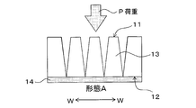
- the front portion 1a of the C-shaped seat cushion frame 1 has an upper surface formed on a surface 11 extending intermittently in the seat width direction WW, and a lower surface side formed in the seat width direction W. It is formed on the surface 12 continuously extending to ⁇ W.
- the upper surface side of the front portion 1a is formed on the surface 11 that extends intermittently, so that the front portion 1a is partitioned into a plurality of small portions 13 in the sheet width direction WW. Is formed in a bag-open shape that opens toward the front F of the seat.
- each small portion 13 present in the central portion in the sheet width direction WW has a symmetrical trapezoidal shape when viewed from the front of the sheet, and each side of the trapezoidal shape is the above-described side.
- a bag-open shape that opens toward the front F of the seat is formed.
- Each small portion 13 present at both end portions in the sheet width direction WW has a left-right asymmetric trapezoidal shape.
- a band-shaped composite material 14 including reinforcing fibers extending in the seat width direction WW on the lower surface 12 side of the front portion 1a of the seat cushion frame 1 is a heat that forms the C-shaped seat cushion frame 1. It is provided so as to be integrated with the plastic resin. This integration can also be realized by adhering the band-shaped composite material 14, and the band-shaped composite material 14 arranged in the mold is made of a thermoplastic resin for constituting the seat cushion frame 1 and the thermoplastic resin. It can also be realized by integrally molding by injection molding or the like. In particular, in the latter case, it is preferable that the strip-shaped composite material 14 uses the same kind or the same thermoplastic resin as the thermoplastic resin constituting the C-shaped frame 1 as the matrix resin.
- the reinforcing fibers of the strip-shaped composite material 14 preferably include carbon fibers.
- substantially the entire seat cushion frame 1 having a C-shaped planar shape is made of a predetermined thermoplastic resin, at least the entire thermoplastic resin portion of the seat cushion frame 1 is formed. It can be integrally molded, making it possible to reduce the weight significantly compared to conventional steel frames, and can greatly reduce the number of parts, the number of assembly steps, and simplify the overall structure. become. Further, the upper surface side of the front portion 1a of the C-shaped frame 1 is formed on a surface 11 that extends intermittently in the sheet width direction WW, and the lower surface side is formed on a surface 12 that extends continuously in the sheet width direction WW.
- a desirable submarine preventing function is obtained in which the load P is gradually absorbed and subsidence of a certain amount or more is prevented.
- this submarine prevention function is different from the sudden displacement prevention by mechanical locking, and the load P is gradually absorbed while the front part gradually curves and deforms downward.
- further displacement is prevented by contact between the end portions of the adjacent upper surface portions, so there is no possibility of sudden impact on the passenger on the seat.
- the front portion 1a of the seat cushion frame 1 is divided into a plurality of small portions 13 having a bag-opening shape that opens toward the seat front F in the seat width direction WW. Therefore, the strength and rigidity of each small portion 13 are structurally maintained, the desired strength and rigidity of the front portion 1a itself are ensured, and the end portions of the upper surface portion of each small portion 13 are in contact with each other. At that time, further deformation and subsidence are more reliably prevented, and submarine prevention performance is realized under desirable conditions.
- the belt-shaped composite material 14 including the reinforcing fibers extending in the seat width direction WW is integrally provided on the lower surface 12 side of the front portion 1a of the seat cushion frame 1 in particular. The desired strength and rigidity of the part 1a itself are further ensured, and the rigidity and strength against the load P from above are increased, and more desirable submarine prevention performance is realized from the viewpoint of load absorption performance.
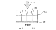
- FIG. 2 shows the opening shape of the plurality of small portions partitioned in the seat width direction WW in the front portion 1a of the seat cushion frame 1 of the above-described embodiment and opening toward the front F of the seat.
- various forms can be adopted.
- a plurality of small portions 22 partitioned in the seat width direction WW are opened to open toward the front of the seat.
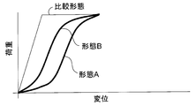
- FIG. 5 shows the schematic characteristics (schematic load-displacement characteristics) in the form A shown in FIG. 2 and the form B shown in FIG. 3 together with the schematic characteristics of the form shown for comparison in FIG.
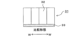
- the plurality of small portions 32 partitioned in the seat width direction WW have a bag-open shape that opens toward the front of the seat, as a belt-like shape.
- the composite material 33 is formed in a quadrangular shape from the lower surface side where the composite material 33 is integrally provided to the upper surface, and the upper surfaces of the small portions 32 are directly adjacent to each other, the upper surface of the front portion 31 has a seat width. It is not formed on a surface that extends intermittently in the direction WW, but is formed on a surface that extends continuously.
- the front portion of the seat cushion frame is gradually and smoothly displaced in the sinking direction with respect to the load from above.
- the form B has a form in which the displacement is further suppressed halfway with respect to the increase in load.
- the load increases more rapidly until the displacement reaches a certain level, and the displacement of the front part is too small, so that the occupant is subjected to a sudden load, that is, an impact force. It has become.
- this comparative embodiment after reaching a certain large load, there is a possibility that the displacement will be advanced even if the load does not increase. This state is a state in which compression fracture proceeds on the upper surface side of the front portion. It is not preferable.
- the side portion of the C-shaped frame in order to give more desirable rigidity and strength to the entire seat cushion frame, it is also possible to add structural measures to the side portion of the C-shaped frame.
- the side portion 41 of the C-shaped frame has a cross section that opens toward the outside of the frame. If comprised in this way, since at least one part of the side part 41 is formed in the cross-sectional shape opened toward the outer side of a flame
- the reinforcing fiber and the resin are provided on at least one of the upper surface and the lower surface of the side portion 41, on both surfaces in the illustrated example, that is, on both the upper surface of the upper portion 42a and the lower surface of the lower portion 42b.
- the reinforcing composite materials 43a and 43b are arranged, and the rigidity and strength of the side portion 41 are appropriately increased.
- the reinforcing composite materials 43a and 43b are arranged on both the upper surface and the lower surface of the side portion 41 in this way, as described above, the upper reinforcing composite material 43a is more than the lower reinforcing composite material 43b. It is preferable that many are arranged.
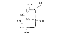
- a structure as shown in FIG. 7 can be adopted.
- the side portion 51 of the C-shaped frame is configured to have a cross section that opens toward the outside of the frame, and the opening cross section is lower than the upper portion 52a.
- the portion 52b is configured to extend longer toward the outside of the frame.
- the upper portion 52a, the lower portion 52b, and the vertical wall portion 52c therebetween are reinforced with reinforcing composite materials 53a, 53b, and 53c including reinforcing fibers.
- the cross-sectional shape opening toward the outer side of the frame causes the frame itself to be broken by a lateral load or a side impact load by the seat belt.
- the frame itself can have a reasonably high rigidity.
- the reinforcing composite materials 53a, 53b, and 53c also preferably include carbon fibers as reinforcing fibers, similarly to the strip-shaped composite material 14 provided on the lower surface side of the front portion.
- the present invention can be applied to any vehicle seat cushion frame made of metal at present.
Landscapes
- Engineering & Computer Science (AREA)
- Aviation & Aerospace Engineering (AREA)
- Transportation (AREA)
- Mechanical Engineering (AREA)
- Seats For Vehicles (AREA)
Abstract
Description
図1は、本発明の一実施形態に係る車両用シートクッションフレームを示している。図1において、1は、車両用シートクッションフレームを示しており、シートクッションフレーム1のリア側には、シートバックフレーム2が回動可能に連結される。シートクッションフレーム1は、そのリア側を開口側とするC形の平面形状を有しており、フロント部1aと両側のサイド部1bを有している。このC形のシートクッションフレーム1は、全体が熱可塑性樹脂、例えば射出成形された熱可塑性樹脂から構成されており、図示例では、側方に向かって開口するC形横断面形状を有する両側のサイド部1bの上面側に、このフレーム部分の剛性、強度を向上するために、少なくともそのフレーム部分延在方向に延びる強化繊維を含む補強用複合材3が、C形のシートクッションフレーム1を構成する熱可塑性樹脂部と一体化されている。一体化は、例えば、一方向に強化繊維が配された複合材3(一方向繊維強化複合材)を、該強化繊維の配向方向をフレーム延在方向として成形型(図示略)内に配置し、該成形型内にフレーム1の熱可塑性樹脂部を形成する熱可塑性樹脂を射出して複合材3と一体化することにより実現できる。この複合材3の強化繊維としては、炭素繊維を含むことが好ましい。また、複合材3を設ける構成とは別に、あるいは、その構成とともに、C形のシートクッションフレーム1を構成する熱可塑性樹脂に強化繊維を含有させることもできる。この強化繊維としても、炭素繊維を含むことが好ましい。
1a、21、31 フロント部
1b、41、51 サイド部
2 シートバックフレーム
3、43a、43b、53a、53b、53c 補強用複合材
11 フロント部の上面
12 フロント部の下面
13,22、32 小部分
14、23、33 帯状複合材
42a、52a サイド部の上部部分
42b、52b サイド部の下部部分
52c サイド部の縦壁部分
Claims (11)
- リア側を開口側とするC形の平面形状を有する車両用シートクッションフレームであって、該C形フレームが熱可塑性樹脂からなるとともに、該C形フレームのフロント部が、上面側がシート幅方向に断続的に延びる面に形成され、かつ、下面側がシート幅方向に連続的に延びる面に形成されている構造を有することを特徴とする車両用シートクッションフレーム。
- 前記熱可塑性樹脂が強化繊維を含む、請求項1に記載の車両用シートクッションフレーム。
- 前記上面側が断続的に延びる面に形成されることによって前記フロント部がシート幅方向に複数の小部分に区画されており、各小部分がシート前方に向かって開口する開袋状形状に形成されている、請求項1または2に記載の車両用シートクッションフレーム。
- 前記フロント部の下面側に、シート幅方向に延びる強化繊維を含む帯状複合材が前記熱可塑性樹脂と一体化されている、請求項1~3のいずれかに記載の車両用シートクッションフレーム。
- 前記複合材が、前記C形フレームを構成する熱可塑性樹脂と同種または同一の熱可塑性樹脂をマトリックス樹脂としている、請求項4に記載の車両用シートクッションフレーム。
- 前記複合材の強化繊維として炭素繊維を含む、請求項4または5に記載の車両用シートクッションフレーム。
- 前記C形フレームのサイド部の少なくとも一部が、フレームの外側に向けて開口する断面を有する、請求項1~6のいずれかに記載の車両用シートクッションフレーム。
- 前記C形フレームのサイド部の少なくとも一部の断面において、上部部分よりも下部部分の方がフレームの外側に向けてより長く延在されている、請求項7に記載の車両用シートクッションフレーム。
- 前記C形フレームのサイド部の上面および下面の少なくとも一方に、強化繊維と樹脂からなる補強用複合材が配置されている、請求項1~8のいずれかに記載の車両用シートクッションフレーム。
- 前記C形フレームのサイド部の上面および下面の両方に、強化繊維と樹脂からなる補強用複合材が配置されているとともに、上面の補強用複合材が下面の補強用複合材よりも多く配置されている、請求項9に記載の車両用シートクッションフレーム。
- 前記補強用複合材の強化繊維として炭素繊維を含む、請求項9または10に記載の車両用シートクッションフレーム。
Priority Applications (4)
| Application Number | Priority Date | Filing Date | Title |
|---|---|---|---|
| US14/398,185 US9393889B2 (en) | 2012-05-11 | 2013-05-09 | Seat cushion frame for vehicle |
| JP2013521693A JP5967490B2 (ja) | 2012-05-11 | 2013-05-09 | 車両用シートクッションフレーム |
| KR1020147031848A KR102050849B1 (ko) | 2012-05-11 | 2013-05-09 | 차량용 시트 쿠션 프레임 |
| EP13787055.6A EP2848461B1 (en) | 2012-05-11 | 2013-05-09 | Seat cushion frame for vehicle |
Applications Claiming Priority (2)
| Application Number | Priority Date | Filing Date | Title |
|---|---|---|---|
| JP2012-109277 | 2012-05-11 | ||
| JP2012109277 | 2012-05-11 |
Publications (1)
| Publication Number | Publication Date |
|---|---|
| WO2013168769A1 true WO2013168769A1 (ja) | 2013-11-14 |
Family
ID=49550801
Family Applications (1)
| Application Number | Title | Priority Date | Filing Date |
|---|---|---|---|
| PCT/JP2013/063043 Ceased WO2013168769A1 (ja) | 2012-05-11 | 2013-05-09 | 車両用シートクッションフレーム |
Country Status (5)
| Country | Link |
|---|---|
| US (1) | US9393889B2 (ja) |
| EP (1) | EP2848461B1 (ja) |
| JP (1) | JP5967490B2 (ja) |
| KR (1) | KR102050849B1 (ja) |
| WO (1) | WO2013168769A1 (ja) |
Cited By (1)
| Publication number | Priority date | Publication date | Assignee | Title |
|---|---|---|---|---|
| WO2018185978A1 (ja) * | 2017-04-03 | 2018-10-11 | 株式会社ジャムコ | 座席ユニット及びその下部構造体 |
Families Citing this family (12)
| Publication number | Priority date | Publication date | Assignee | Title |
|---|---|---|---|---|
| US11033125B2 (en) | 2010-05-14 | 2021-06-15 | Mcs Industries, Inc. | Hanging apparatus |
| JP6266320B2 (ja) * | 2013-11-19 | 2018-01-24 | テイ・エス テック株式会社 | シートフレーム |
| US10194750B2 (en) | 2015-04-13 | 2019-02-05 | Steelcase Inc. | Seating arrangement |
| US10966527B2 (en) | 2017-06-09 | 2021-04-06 | Steelcase Inc. | Seating arrangement and method of construction |
| US11259637B2 (en) | 2015-04-13 | 2022-03-01 | Steelcase Inc. | Seating arrangement |
| US10021984B2 (en) | 2015-04-13 | 2018-07-17 | Steelcase Inc. | Seating arrangement |
| JP6468070B2 (ja) * | 2015-05-22 | 2019-02-13 | トヨタ紡織株式会社 | 乗物用シート |
| US11246431B2 (en) | 2016-06-23 | 2022-02-15 | Mcs Industries, Inc. | Hanging apparatus and bracket thereof |
| US10681995B2 (en) | 2016-06-23 | 2020-06-16 | Mcs Industries, Inc. | Hanging apparatus and bracket for hanging a frame apparatus |
| US11059403B2 (en) | 2018-05-17 | 2021-07-13 | Toyota Motor Engineering & Manufacturing North America, Inc. | Reinforced rear seat assemblies for vehicles |
| ES3035683T3 (en) | 2019-02-21 | 2025-09-08 | Steelcase Inc | Body support member |
| US11357329B2 (en) | 2019-12-13 | 2022-06-14 | Steelcase Inc. | Body support assembly and methods for the use and assembly thereof |
Citations (5)
| Publication number | Priority date | Publication date | Assignee | Title |
|---|---|---|---|---|
| JP2003265261A (ja) * | 2002-03-19 | 2003-09-24 | Daihatsu Motor Co Ltd | 樹脂シートフレームの支持構造 |
| JP2004338632A (ja) | 2003-05-16 | 2004-12-02 | Imasen Electric Ind Co Ltd | 車両用シート |
| JP2007504040A (ja) * | 2003-09-05 | 2007-03-01 | カイペル ゲーエムベーハー アンド カンパニー カーゲー | 潜り込み防止用斜面付き車両座席 |
| JP2009541108A (ja) * | 2006-06-23 | 2009-11-26 | ジョンソン・コントロールズ・ゲー・エム・ベー・ハー | シート部分とアンチサブマリン拘束装置とを備えた車両シート、拘束装置および製造方法 |
| US20100001479A1 (en) * | 2008-07-03 | 2010-01-07 | Dalton Trybus | Vehicle seat with cushion carrier |
Family Cites Families (21)
| Publication number | Priority date | Publication date | Assignee | Title |
|---|---|---|---|---|
| JPS55114261U (ja) * | 1979-02-05 | 1980-08-12 | ||
| US5240310A (en) * | 1989-11-30 | 1993-08-31 | Bayer Aktiengesellschaft | Seat base for vehicle seats |
| US5284381A (en) * | 1991-11-19 | 1994-02-08 | Tachi-S Co. Ltd. | Structure of seat cushion frame in automotive seat |
| US5236247A (en) * | 1992-02-14 | 1993-08-17 | Hoover Universal, Inc. | Insert molded composite plastic seat cushion frame |
| US5575533A (en) * | 1994-02-25 | 1996-11-19 | Concept Analysis Corp. | Blow molded seat frame with integral reinforcement |
| US6059369A (en) * | 1997-05-01 | 2000-05-09 | Lear Corporation | Composite vehicle seat back frame and method of manufacturing thereof |
| US20050168041A1 (en) * | 2000-10-04 | 2005-08-04 | Glance Patrick M. | Thin, double-wall molded seat frame system |
| WO2004024424A1 (de) * | 2002-09-15 | 2004-03-25 | Rcc Regional Compact Car Ag | Strukturbauteil aus faserverstärktem thermoplastischem kunststoff |
| DE10347550B3 (de) * | 2003-10-14 | 2005-03-10 | Faurecia Autositze Gmbh & Co | Sitzteil für ein Fahrzeugsitz |
| EP2057034A1 (en) * | 2006-08-14 | 2009-05-13 | Basf Se | Composite component |
| WO2009154909A1 (en) * | 2008-05-28 | 2009-12-23 | Dow Global Technologies Inc. | Improved vehicular seat back assembly |
| US7850247B2 (en) * | 2008-09-19 | 2010-12-14 | Lear Corporation | Vehicle seat assembly with polymeric cushion pan |
| US8371655B2 (en) * | 2008-10-20 | 2013-02-12 | Nhk Spring Co., Ltd. | Seat cushion frame structure of seat for vehicle and seat for vehicle with seat cushion frame structure |
| DE202008015401U1 (de) * | 2008-11-19 | 2010-04-08 | Lanxess Deutschland Gmbh | Sitzstrukturen |
| CN102666197B (zh) * | 2009-09-16 | 2016-05-04 | 约翰逊控股公司 | 用于机动车的结构元件 |
| US8308235B2 (en) * | 2010-03-11 | 2012-11-13 | Honda Motor Co. | Vehicle seat assembly |
| US8408655B2 (en) * | 2010-08-27 | 2013-04-02 | Honda Motor Co., Ltd. | Vehicle seat assembly |
| EP2616272B1 (en) * | 2010-09-14 | 2017-06-21 | Basf Se | Energy absorbing bracket for a seat of a vehicle |
| JP5561129B2 (ja) * | 2010-11-30 | 2014-07-30 | トヨタ紡織株式会社 | 車両用シート |
| DE102011002079A1 (de) * | 2011-04-15 | 2012-10-18 | C. Rob. Hammerstein Gmbh & Co. Kg | Sitzkörper für einen Kraftfahrzeugsitz |
| US9376043B2 (en) * | 2011-11-14 | 2016-06-28 | Ford Global Technologies, Llc | Cushion pan for a vehicle seat assembly |
-
2013
- 2013-05-09 WO PCT/JP2013/063043 patent/WO2013168769A1/ja not_active Ceased
- 2013-05-09 EP EP13787055.6A patent/EP2848461B1/en not_active Not-in-force
- 2013-05-09 JP JP2013521693A patent/JP5967490B2/ja not_active Expired - Fee Related
- 2013-05-09 US US14/398,185 patent/US9393889B2/en not_active Expired - Fee Related
- 2013-05-09 KR KR1020147031848A patent/KR102050849B1/ko not_active Expired - Fee Related
Patent Citations (5)
| Publication number | Priority date | Publication date | Assignee | Title |
|---|---|---|---|---|
| JP2003265261A (ja) * | 2002-03-19 | 2003-09-24 | Daihatsu Motor Co Ltd | 樹脂シートフレームの支持構造 |
| JP2004338632A (ja) | 2003-05-16 | 2004-12-02 | Imasen Electric Ind Co Ltd | 車両用シート |
| JP2007504040A (ja) * | 2003-09-05 | 2007-03-01 | カイペル ゲーエムベーハー アンド カンパニー カーゲー | 潜り込み防止用斜面付き車両座席 |
| JP2009541108A (ja) * | 2006-06-23 | 2009-11-26 | ジョンソン・コントロールズ・ゲー・エム・ベー・ハー | シート部分とアンチサブマリン拘束装置とを備えた車両シート、拘束装置および製造方法 |
| US20100001479A1 (en) * | 2008-07-03 | 2010-01-07 | Dalton Trybus | Vehicle seat with cushion carrier |
Cited By (3)
| Publication number | Priority date | Publication date | Assignee | Title |
|---|---|---|---|---|
| WO2018185978A1 (ja) * | 2017-04-03 | 2018-10-11 | 株式会社ジャムコ | 座席ユニット及びその下部構造体 |
| JP2018176769A (ja) * | 2017-04-03 | 2018-11-15 | 株式会社ジャムコ | 座席ユニット及びその下部構造体 |
| US11753168B2 (en) | 2017-04-03 | 2023-09-12 | Jamco Corporation | Seat unit and lower structure thereof |
Also Published As
| Publication number | Publication date |
|---|---|
| US20150130254A1 (en) | 2015-05-14 |
| EP2848461A1 (en) | 2015-03-18 |
| JPWO2013168769A1 (ja) | 2016-01-07 |
| US9393889B2 (en) | 2016-07-19 |
| JP5967490B2 (ja) | 2016-08-10 |
| EP2848461B1 (en) | 2017-07-05 |
| EP2848461A4 (en) | 2015-12-30 |
| KR20150016506A (ko) | 2015-02-12 |
| KR102050849B1 (ko) | 2019-12-02 |
Similar Documents
| Publication | Publication Date | Title |
|---|---|---|
| JP5967490B2 (ja) | 車両用シートクッションフレーム | |
| US8276975B2 (en) | FRP panel for automobile | |
| JP6018643B2 (ja) | 中空断面を有する繊維複合補強材が内蔵されているバンパーバックビーム及びこれを有するバンパーの製造方法 | |
| EP2899067B1 (en) | Hybrid seat frame for vehicle | |
| JP6120460B2 (ja) | 自動車用バンパー | |
| JPWO2015080037A1 (ja) | 自動車用バンパー | |
| CN105579329B (zh) | 改进的用于机动车车身的侧立柱 | |
| US9434285B2 (en) | Frame structure for seat back | |
| JP6217394B2 (ja) | 車両用シートクッションフレームおよびその製造方法 | |
| WO2013133146A1 (ja) | ビーム成形品およびそれを用いたバンパレインフォース | |
| JP5304302B2 (ja) | アームレスト | |
| US20190193656A1 (en) | Vehicle bumper device | |
| JP4093124B2 (ja) | 自動車のセンターピラー構造 | |
| JPWO2012153602A1 (ja) | 車体前部構造体 | |
| JP5910293B2 (ja) | 樹脂成形品の強化構造 | |
| US20160136921A1 (en) | Fiber-reinforced resin member | |
| KR102383484B1 (ko) | 복합재료를 이용한 차량의 강성부재 | |
| KR101327567B1 (ko) | 자동차용 범퍼 백빔 | |
| JPWO2012153601A1 (ja) | 車体前部構造体 | |
| KR102294003B1 (ko) | 차량용 범퍼 | |
| KR20180097192A (ko) | 시트백 프레임 및 그 제조방법 | |
| WO2024201769A1 (ja) | センターピラー | |
| JP2004330849A (ja) | 樹脂製車体部品の構造 |
Legal Events
| Date | Code | Title | Description |
|---|---|---|---|
| ENP | Entry into the national phase |
Ref document number: 2013521693 Country of ref document: JP Kind code of ref document: A |
|
| 121 | Ep: the epo has been informed by wipo that ep was designated in this application |
Ref document number: 13787055 Country of ref document: EP Kind code of ref document: A1 |
|
| REEP | Request for entry into the european phase |
Ref document number: 2013787055 Country of ref document: EP |
|
| WWE | Wipo information: entry into national phase |
Ref document number: 2013787055 Country of ref document: EP |
|
| WWE | Wipo information: entry into national phase |
Ref document number: 14398185 Country of ref document: US |
|
| NENP | Non-entry into the national phase |
Ref country code: DE |
|
| ENP | Entry into the national phase |
Ref document number: 20147031848 Country of ref document: KR Kind code of ref document: A |