WO2013168912A1 - 담체에 담지된 코어-쉘 입자의 제조방법 및 이에 의해 제조된 담체에 담지된 코어-쉘 입자 - Google Patents
담체에 담지된 코어-쉘 입자의 제조방법 및 이에 의해 제조된 담체에 담지된 코어-쉘 입자 Download PDFInfo
- Publication number
- WO2013168912A1 WO2013168912A1 PCT/KR2013/003410 KR2013003410W WO2013168912A1 WO 2013168912 A1 WO2013168912 A1 WO 2013168912A1 KR 2013003410 W KR2013003410 W KR 2013003410W WO 2013168912 A1 WO2013168912 A1 WO 2013168912A1
- Authority
- WO
- WIPO (PCT)
- Prior art keywords
- core
- carrier
- shell particles
- metal
- shell
- Prior art date
- Legal status (The legal status is an assumption and is not a legal conclusion. Google has not performed a legal analysis and makes no representation as to the accuracy of the status listed.)
- Ceased
Links
Classifications
-
- H—ELECTRICITY
- H01—ELECTRIC ELEMENTS
- H01M—PROCESSES OR MEANS, e.g. BATTERIES, FOR THE DIRECT CONVERSION OF CHEMICAL ENERGY INTO ELECTRICAL ENERGY
- H01M4/00—Electrodes
- H01M4/86—Inert electrodes with catalytic activity, e.g. for fuel cells
- H01M4/8647—Inert electrodes with catalytic activity, e.g. for fuel cells consisting of more than one material, e.g. consisting of composites
- H01M4/8657—Inert electrodes with catalytic activity, e.g. for fuel cells consisting of more than one material, e.g. consisting of composites layered
-
- B—PERFORMING OPERATIONS; TRANSPORTING
- B01—PHYSICAL OR CHEMICAL PROCESSES OR APPARATUS IN GENERAL
- B01J—CHEMICAL OR PHYSICAL PROCESSES, e.g. CATALYSIS OR COLLOID CHEMISTRY; THEIR RELEVANT APPARATUS
- B01J23/00—Catalysts comprising metals or metal oxides or hydroxides, not provided for in group B01J21/00
- B01J23/38—Catalysts comprising metals or metal oxides or hydroxides, not provided for in group B01J21/00 of noble metals
- B01J23/40—Catalysts comprising metals or metal oxides or hydroxides, not provided for in group B01J21/00 of noble metals of the platinum group metals
- B01J23/42—Platinum
-
- B—PERFORMING OPERATIONS; TRANSPORTING
- B01—PHYSICAL OR CHEMICAL PROCESSES OR APPARATUS IN GENERAL
- B01J—CHEMICAL OR PHYSICAL PROCESSES, e.g. CATALYSIS OR COLLOID CHEMISTRY; THEIR RELEVANT APPARATUS
- B01J13/00—Colloid chemistry, e.g. the production of colloidal materials or their solutions, not otherwise provided for; Making microcapsules or microballoons
-
- B—PERFORMING OPERATIONS; TRANSPORTING
- B01—PHYSICAL OR CHEMICAL PROCESSES OR APPARATUS IN GENERAL
- B01J—CHEMICAL OR PHYSICAL PROCESSES, e.g. CATALYSIS OR COLLOID CHEMISTRY; THEIR RELEVANT APPARATUS
- B01J23/00—Catalysts comprising metals or metal oxides or hydroxides, not provided for in group B01J21/00
- B01J23/70—Catalysts comprising metals or metal oxides or hydroxides, not provided for in group B01J21/00 of the iron group metals or copper
- B01J23/89—Catalysts comprising metals or metal oxides or hydroxides, not provided for in group B01J21/00 of the iron group metals or copper combined with noble metals
- B01J23/892—Nickel and noble metals
-
- B—PERFORMING OPERATIONS; TRANSPORTING
- B01—PHYSICAL OR CHEMICAL PROCESSES OR APPARATUS IN GENERAL
- B01J—CHEMICAL OR PHYSICAL PROCESSES, e.g. CATALYSIS OR COLLOID CHEMISTRY; THEIR RELEVANT APPARATUS
- B01J35/00—Catalysts, in general, characterised by their form or physical properties
- B01J35/30—Catalysts, in general, characterised by their form or physical properties characterised by their physical properties
- B01J35/396—Distribution of the active metal ingredient
- B01J35/397—Egg shell like
-
- B—PERFORMING OPERATIONS; TRANSPORTING
- B01—PHYSICAL OR CHEMICAL PROCESSES OR APPARATUS IN GENERAL
- B01J—CHEMICAL OR PHYSICAL PROCESSES, e.g. CATALYSIS OR COLLOID CHEMISTRY; THEIR RELEVANT APPARATUS
- B01J35/00—Catalysts, in general, characterised by their form or physical properties
- B01J35/40—Catalysts, in general, characterised by their form or physical properties characterised by dimensions, e.g. grain size
- B01J35/45—Nanoparticles
-
- B—PERFORMING OPERATIONS; TRANSPORTING
- B01—PHYSICAL OR CHEMICAL PROCESSES OR APPARATUS IN GENERAL
- B01J—CHEMICAL OR PHYSICAL PROCESSES, e.g. CATALYSIS OR COLLOID CHEMISTRY; THEIR RELEVANT APPARATUS
- B01J37/00—Processes, in general, for preparing catalysts; Processes, in general, for activation of catalysts
- B01J37/02—Impregnation, coating or precipitation
- B01J37/03—Precipitation; Co-precipitation
- B01J37/031—Precipitation
- B01J37/035—Precipitation on carriers
-
- B—PERFORMING OPERATIONS; TRANSPORTING
- B01—PHYSICAL OR CHEMICAL PROCESSES OR APPARATUS IN GENERAL
- B01J—CHEMICAL OR PHYSICAL PROCESSES, e.g. CATALYSIS OR COLLOID CHEMISTRY; THEIR RELEVANT APPARATUS
- B01J37/00—Processes, in general, for preparing catalysts; Processes, in general, for activation of catalysts
- B01J37/16—Reducing
-
- H—ELECTRICITY
- H01—ELECTRIC ELEMENTS
- H01M—PROCESSES OR MEANS, e.g. BATTERIES, FOR THE DIRECT CONVERSION OF CHEMICAL ENERGY INTO ELECTRICAL ENERGY
- H01M4/00—Electrodes
- H01M4/86—Inert electrodes with catalytic activity, e.g. for fuel cells
- H01M4/88—Processes of manufacture
- H01M4/8825—Methods for deposition of the catalytic active composition
-
- H—ELECTRICITY
- H01—ELECTRIC ELEMENTS
- H01M—PROCESSES OR MEANS, e.g. BATTERIES, FOR THE DIRECT CONVERSION OF CHEMICAL ENERGY INTO ELECTRICAL ENERGY
- H01M4/00—Electrodes
- H01M4/86—Inert electrodes with catalytic activity, e.g. for fuel cells
- H01M4/90—Selection of catalytic material
- H01M4/92—Metals of platinum group
- H01M4/925—Metals of platinum group supported on carriers, e.g. powder carriers
-
- H—ELECTRICITY
- H01—ELECTRIC ELEMENTS
- H01M—PROCESSES OR MEANS, e.g. BATTERIES, FOR THE DIRECT CONVERSION OF CHEMICAL ENERGY INTO ELECTRICAL ENERGY
- H01M8/00—Fuel cells; Manufacture thereof
- H01M8/02—Details
-
- B—PERFORMING OPERATIONS; TRANSPORTING
- B01—PHYSICAL OR CHEMICAL PROCESSES OR APPARATUS IN GENERAL
- B01J—CHEMICAL OR PHYSICAL PROCESSES, e.g. CATALYSIS OR COLLOID CHEMISTRY; THEIR RELEVANT APPARATUS
- B01J35/00—Catalysts, in general, characterised by their form or physical properties
- B01J35/30—Catalysts, in general, characterised by their form or physical properties characterised by their physical properties
- B01J35/33—Electric or magnetic properties
-
- B—PERFORMING OPERATIONS; TRANSPORTING
- B01—PHYSICAL OR CHEMICAL PROCESSES OR APPARATUS IN GENERAL
- B01J—CHEMICAL OR PHYSICAL PROCESSES, e.g. CATALYSIS OR COLLOID CHEMISTRY; THEIR RELEVANT APPARATUS
- B01J37/00—Processes, in general, for preparing catalysts; Processes, in general, for activation of catalysts
- B01J37/02—Impregnation, coating or precipitation
- B01J37/024—Multiple impregnation or coating
- B01J37/0244—Coatings comprising several layers
-
- B—PERFORMING OPERATIONS; TRANSPORTING
- B82—NANOTECHNOLOGY
- B82Y—SPECIFIC USES OR APPLICATIONS OF NANOSTRUCTURES; MEASUREMENT OR ANALYSIS OF NANOSTRUCTURES; MANUFACTURE OR TREATMENT OF NANOSTRUCTURES
- B82Y30/00—Nanotechnology for materials or surface science, e.g. nanocomposites
-
- B—PERFORMING OPERATIONS; TRANSPORTING
- B82—NANOTECHNOLOGY
- B82Y—SPECIFIC USES OR APPLICATIONS OF NANOSTRUCTURES; MEASUREMENT OR ANALYSIS OF NANOSTRUCTURES; MANUFACTURE OR TREATMENT OF NANOSTRUCTURES
- B82Y40/00—Manufacture or treatment of nanostructures
-
- Y—GENERAL TAGGING OF NEW TECHNOLOGICAL DEVELOPMENTS; GENERAL TAGGING OF CROSS-SECTIONAL TECHNOLOGIES SPANNING OVER SEVERAL SECTIONS OF THE IPC; TECHNICAL SUBJECTS COVERED BY FORMER USPC CROSS-REFERENCE ART COLLECTIONS [XRACs] AND DIGESTS
- Y02—TECHNOLOGIES OR APPLICATIONS FOR MITIGATION OR ADAPTATION AGAINST CLIMATE CHANGE
- Y02E—REDUCTION OF GREENHOUSE GAS [GHG] EMISSIONS, RELATED TO ENERGY GENERATION, TRANSMISSION OR DISTRIBUTION
- Y02E60/00—Enabling technologies; Technologies with a potential or indirect contribution to GHG emissions mitigation
- Y02E60/30—Hydrogen technology
- Y02E60/50—Fuel cells
-
- Y—GENERAL TAGGING OF NEW TECHNOLOGICAL DEVELOPMENTS; GENERAL TAGGING OF CROSS-SECTIONAL TECHNOLOGIES SPANNING OVER SEVERAL SECTIONS OF THE IPC; TECHNICAL SUBJECTS COVERED BY FORMER USPC CROSS-REFERENCE ART COLLECTIONS [XRACs] AND DIGESTS
- Y10—TECHNICAL SUBJECTS COVERED BY FORMER USPC
- Y10S—TECHNICAL SUBJECTS COVERED BY FORMER USPC CROSS-REFERENCE ART COLLECTIONS [XRACs] AND DIGESTS
- Y10S977/00—Nanotechnology
- Y10S977/70—Nanostructure
- Y10S977/773—Nanoparticle, i.e. structure having three dimensions of 100 nm or less
- Y10S977/775—Nanosized powder or flake, e.g. nanosized catalyst
- Y10S977/777—Metallic powder or flake
-
- Y—GENERAL TAGGING OF NEW TECHNOLOGICAL DEVELOPMENTS; GENERAL TAGGING OF CROSS-SECTIONAL TECHNOLOGIES SPANNING OVER SEVERAL SECTIONS OF THE IPC; TECHNICAL SUBJECTS COVERED BY FORMER USPC CROSS-REFERENCE ART COLLECTIONS [XRACs] AND DIGESTS
- Y10—TECHNICAL SUBJECTS COVERED BY FORMER USPC
- Y10S—TECHNICAL SUBJECTS COVERED BY FORMER USPC CROSS-REFERENCE ART COLLECTIONS [XRACs] AND DIGESTS
- Y10S977/00—Nanotechnology
- Y10S977/70—Nanostructure
- Y10S977/81—Of specified metal or metal alloy composition
-
- Y—GENERAL TAGGING OF NEW TECHNOLOGICAL DEVELOPMENTS; GENERAL TAGGING OF CROSS-SECTIONAL TECHNOLOGIES SPANNING OVER SEVERAL SECTIONS OF THE IPC; TECHNICAL SUBJECTS COVERED BY FORMER USPC CROSS-REFERENCE ART COLLECTIONS [XRACs] AND DIGESTS
- Y10—TECHNICAL SUBJECTS COVERED BY FORMER USPC
- Y10S—TECHNICAL SUBJECTS COVERED BY FORMER USPC CROSS-REFERENCE ART COLLECTIONS [XRACs] AND DIGESTS
- Y10S977/00—Nanotechnology
- Y10S977/84—Manufacture, treatment, or detection of nanostructure
- Y10S977/89—Deposition of materials, e.g. coating, cvd, or ald
- Y10S977/892—Liquid phase deposition
-
- Y—GENERAL TAGGING OF NEW TECHNOLOGICAL DEVELOPMENTS; GENERAL TAGGING OF CROSS-SECTIONAL TECHNOLOGIES SPANNING OVER SEVERAL SECTIONS OF THE IPC; TECHNICAL SUBJECTS COVERED BY FORMER USPC CROSS-REFERENCE ART COLLECTIONS [XRACs] AND DIGESTS
- Y10—TECHNICAL SUBJECTS COVERED BY FORMER USPC
- Y10S—TECHNICAL SUBJECTS COVERED BY FORMER USPC CROSS-REFERENCE ART COLLECTIONS [XRACs] AND DIGESTS
- Y10S977/00—Nanotechnology
- Y10S977/84—Manufacture, treatment, or detection of nanostructure
- Y10S977/895—Manufacture, treatment, or detection of nanostructure having step or means utilizing chemical property
- Y10S977/896—Chemical synthesis, e.g. chemical bonding or breaking
-
- Y—GENERAL TAGGING OF NEW TECHNOLOGICAL DEVELOPMENTS; GENERAL TAGGING OF CROSS-SECTIONAL TECHNOLOGIES SPANNING OVER SEVERAL SECTIONS OF THE IPC; TECHNICAL SUBJECTS COVERED BY FORMER USPC CROSS-REFERENCE ART COLLECTIONS [XRACs] AND DIGESTS
- Y10—TECHNICAL SUBJECTS COVERED BY FORMER USPC
- Y10S—TECHNICAL SUBJECTS COVERED BY FORMER USPC CROSS-REFERENCE ART COLLECTIONS [XRACs] AND DIGESTS
- Y10S977/00—Nanotechnology
- Y10S977/902—Specified use of nanostructure
- Y10S977/932—Specified use of nanostructure for electronic or optoelectronic application
- Y10S977/948—Energy storage/generating using nanostructure, e.g. fuel cell, battery
Definitions
- Nanoparticles are particles having a nanoscale particle size, which are bulk materials because of the quantum confinement effect and the large specific surface area where the energy required for electron transfer varies with the size of the material. Are very different from optical, electrical and magnetic properties. Therefore, due to these properties, much attention has been focused on its application in the field of catalysts, electromagnetism, optics, and medicine. Nanoparticles are intermediates between bulk and molecules and allow for the synthesis of nanoparticles in terms of two ways of approach: the "top-down” approach and the “bottom-up” approach.
- Synthesis methods of metal nanoparticles include a method of reducing metal silver with a reducing agent in solution, a method using gamma rays, and an electrochemical method, but conventional methods are difficult to synthesize nanoparticles having a uniform size and shape.
- the use of organic solvents has made economical mass production of high quality nanoparticles difficult for various reasons, such as environmental pollution and high cost.
- Another object of the present invention is to provide a core-shell particles supported on a carrier prepared by the above production method.
- Another problem to be solved by the present invention is to provide a fuel cell catalyst and a fuel cell including the core-shell particles supported on the carrier prepared by the above production method.
- One embodiment of the present invention comprises the steps of adding a first metal supported on a carrier to a solvent to form a solution; Adjusting the pH of the solution to 7-14 and adding a metal salt of a second metal; And adding a reducing agent to the solution, and forming a shell including a second metal on the surface of the core particle including the first metal to form core-shell particles. It provides a method for producing core-shell particles supported on.
- a core supported on a carrier prepared by the manufacturing method In one embodiment of the present invention, a core supported on a carrier prepared by the manufacturing method
- a catalyst for a fuel cell comprising shell particles.
- One embodiment of the present invention provides a fuel cell comprising the catalyst for the fuel cell.
- FIG. 1 is a flowchart illustrating a method of preparing core-shell particles according to an embodiment of the present invention.
- FIG. 2 shows a high resolution transmission electron microscope (HR-TEM) image of core-shell particles prepared according to Example 1.
- HR-TEM transmission electron microscope
- FIG. 3 shows the results of analyzing the content of the elements located along the line of the arrow in the image of FIG.
- FIG. 4 shows the core point as P1 and the shell point as P2 in the HR-TEM image of the core-shell particles prepared according to Example 1.
- FIG. 4 shows the core point as P1 and the shell point as P2 in the HR-TEM image of the core-shell particles prepared according to Example 1.
- Figure 5 shows a transmission electron microscope (TEM) image of Comparative Example 1.
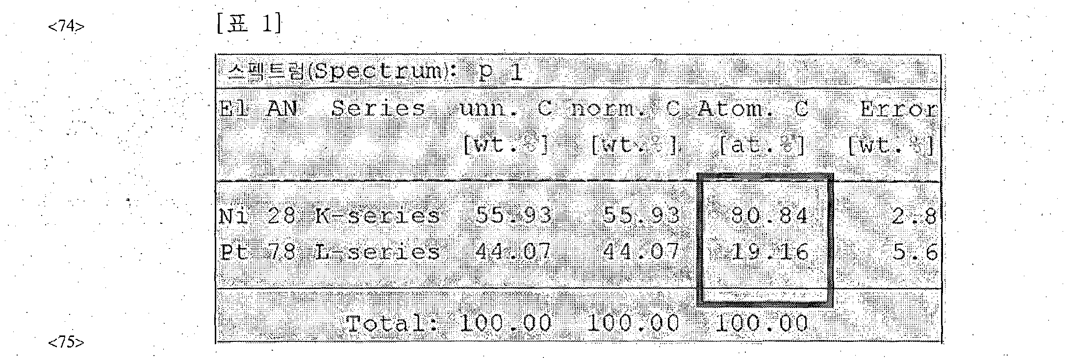
- FIG. 6 shows the results of elemental analysis of the points indicated by Spectrum Spectrum 1) in the image of FIG. 5.
- Figure 7 shows a transmission electron microscope (TEM) image of Comparative Example 2.
- FIG. 8 shows the results of elemental analysis of the points indicated by Spectrum 2 in the image of FIG. 7.
- FIG. 1 is a flowchart illustrating a method of preparing core-shell particles according to an embodiment of the present invention.
- a solution is formed by adding a first metal supported on a carrier to a solvent (S1010).
- the first metal may be selected from the group consisting of metals, metalloids, lanthanum group metals, and actinium group metals belonging to Groups 3 to 15 of the periodic table.
- ruthenium rhodium (Rh), molybdenum (Mo), osmium (0s), iridium (Ir), rhenium (Re), palladium (Pd), vanadium (V), tungsten 0, cobalt (Co) , Iron (Fe), selenium (Se), nickel (Ni), bismuth (Bi), tin (Sn), crumb (Cr), titanium (Ti), cerium (Ce), silver (Ag) and copper (Cu) It may be selected from the group consisting of. Even more specifically nickel (Ni).
- the first metal may be different from the second metal.
- the base carrier is not limited as long as it can support the first metal.
- the carrier may be a carbon-based material or inorganic fine particles.
- Carbon-based materials include carbon black, carbon nanotubes (CNT), graphite, graphene, activated carbon, mesoporous carbon, carbon fiber and carbon nano wire
- the carbon blocks include denka black, ketjen black or acetylene black.
- the inorganic fine particles alumina, silica, titania, zirconia and the like may be used, but generally carbon-based materials may be used.
- the method of supporting the first metal on the carrier is a known conventional method, and is not particularly limited.
- the solvent may be a solvent including water.
- the solvent is for dispersing the first metal particles supported on the carrier, and may be water or a mixture of water and an alcohol of ( ⁇ ), and more specifically, water.
- the forming of the solution may be performed at room temperature. Specifically, the step of forming the solution may be carried out at a temperature in the range of 4t 35 ° C, more specifically 15t 28 ° C.
- the solvent is an organic solvent
- the interface of the manufactured core-shell particles is hydrophobic, when they are put in water, the particles aggregate together so that they are not dispersed in water. Therefore, there is a problem in that it is limited in use because it can not be used dispersed in water.
- the present invention uses water as the solvent, there is an advantage in that the solution can be formed at low temperature, specifically at room temperature. Therefore, there is an advantage that there is no environmental pollution, it is possible to mass production at a low cost, there is a cost saving effect.
- the manufacturing method may not use a surfactant.
- the pH of the solution is adjusted to 7-14, and the metal salt of the second metal is added.
- the pH of the solution may be adjusted by adding a base solution.
- a base solution selected from the group consisting of sodium hydroxide (NaOH), barium hydroxide (Ba (0H) 2 ), potassium hydroxide (K0H), calcium hydroxide (Ca (0H) 2 ) and lithium hydroxide (LiOH) is added.
- NaOH sodium hydroxide
- Ba (0H) 2 barium hydroxide
- K0H potassium hydroxide
- Ca (0H) 2 calcium hydroxide
- LiOH lithium hydroxide
- the pH of the solution When the pH of the solution is adjusted to a basicity of 7 to 14, the surface charge of the core becomes negatively charged, so that it can be easily combined with the cationic complex of the metal salt of the second metal, thereby forming a shell on the surface of the core.
- the pH of the solution may be adjusted to 10 to 12 basicity. More specifically, the pH of the solution may be adjusted to 11.
- the second metal may be selected from the group consisting of metals, metalloids, lanthanum group metals, and actinium group metals belonging to Groups 3 to 15 of the periodic table.
- Platinum (Pt), Ruthenium (Ru), Rhodium (Rh), Molybdenum (Mo), Osmium (0s), Iridium (Ir), Rhenium (Re), Palladium (Pd), Vanadium (V), Tungsten 00 , Cobalt (Co), Iron (Fe), Selenium (Se), Nickel (Ni), Bismuth (Bi), Tin (Sn), Chromium (Cr), Titanium (Ti), Gold (Au), Cerium (Ce) , Silver (Ag) and copper (Cu) may be at least one selected from the group consisting of. More specifically, it may be one selected from the group consisting of platinum (Pt) A gold (Au), silver (Ag), and palatum (Pd), and even more specifically, platinum (Pt).
- the metal salt of the second metal may be ionized into a cationic complex.
- the metal salts When ionized in aqueous solution, the metal salts are positively charged when they are present in the form of a cation complex, making them easier to dissipate from the surface of the negatively charged core. Can be combined.
- the metal salt of the second metal may be specifically represented by Formula 1 below.
- X may be selected from the group consisting of metalloid, lanthanum metal and actinium metal belonging to groups 3 to 15 of the periodic table, specifically, platinum (Pt), ruthenium (Ru), Rhodium (Rh), Molybdenum (Mo), Osmium (0s), Iridium (Ir), Rhenium (Re), Pallet (Pd), Vanadium (V), Tungsten (W), Cobalt (Co), Iron (Fe) , Selenium (Se), nickel (Ni), bismuth (Bi), tin (Sn), crumb (Cr), titanium (Ti), gold (Au), cerium (Ce), silver (Ag) and copper (Cu) It may be selected from the group consisting of. More specifically, it may be one selected from the group consisting of platinum (Pt), gold (Au), silver (Ag), and parallax (Pd). X may be different from the nearly U metal.
- A may be (N3 ⁇ 4) , (C3 ⁇ 4NH 2 ) or (3 ⁇ 4 ⁇ ).
- B may be a monovalent anion, and specifically, N0 3 _ , N0 2 ' , OH “ , Cl “ , Br " and
- It may be selected from the group consisting of ⁇ .
- M may be 2, 4, or 6, and n may be an integer of 1 to 7.
- Pt (N3 ⁇ 4) 4 (N0 3 ) 2 is ionized
- the molar ratio of the first metal to the second metal in the solution is
- the number of moles of the first metal is less than 1 times the number of moles of the second metal, the amount of the cores may be unsatisfactory, so that the formation of the core-shell structure may be difficult.
- the number of moles of the first metal exceeds 10 times the number of moles of the second metal, the shell may become too thick and the size of the core-shell particles may be too large. Do.
- a reducing agent is added to the solution, and a shell containing a second metal is formed on the surface of the core particle containing the first metal (S1030).
- the core shell shell particles of the two-layer structure supported on the carrier may be formed.
- the reactant may be added after reacting for 5 minutes to 120 minutes, specifically 10 minutes to 1 hour, more specifically 20 minutes to 40 minutes.
- the core from "one embodiment of the invention - forming a shell (core-shell) particles have certain metal salts of the reducing agent to the core particle and a second metal hours in a solution, in particular 5 to 120 minutes Specifically, the reaction may be performed for 20 to 90 minutes to form core-shell particles.
- adding the reducing agent and forming the core-shell particles may be performed at room temperature.
- the step of preparing the core-shell particles may be carried out at a temperature in the range of 4 ° C ⁇ 35 ° C, more specifically 15 ° 028 ° C.
- the production method exhibits the same or superior physical properties as those of forming core-shell particles by reducing metal acetylacetonate-based or metal carbonyl-based precursors which undergo a reduction reaction at high temperature.
- Core-shell particles can be formed. That is, the core-shell particles can be formed under milder conditions, which is advantageous in view of the economical process.
- the reducing agent is a strong reducing agent of -0.23V or less, specifically, -4V or more and -0.23V or less, and can reduce the dissolved metal ions to precipitate as metal particles. It will not specifically limit, if it has a reducing power which is.
- Such a reducing agent consists of, for example, NaBH 4 , NH 2 NH 2) LiAlH 4 and LiBEt 3 H. It may be at least one selected from the group. '
- the second metal salt is reduced by a reducing agent at a predetermined rate to form a nano-sized shell including the second metal.
- a shell including the second metal may be formed on the surface of the core particle including the above-described first metal, thereby forming core-shell particles.
- the shell may be present in at least one region of the outer surface of the core particle and may be present in a form surrounding the front surface of the outer surface of the core.
- the average particle diameter of the core-shell particles is 2 nm to
- the particle diameter of the core particles may be lnm to 200nm, specifically lnm to 50nm, more specifically lnm to ⁇ .
- the thickness of the shell may be 0.5 to 50 ⁇ , specifically 0.5nm to lOnm, more specifically 0.5nm to 5nm.
- the second metal salt is Pt (N3 ⁇ 4) 4 (N0 3 ) ⁇ containing platinum (Pt), sodium borohydride
- Pt 1 ⁇ 2 is reduced to Pt 0 , and a shell including platinum (Pt) having a thickness of 0.5 nm to 100 m can be formed. .
- the particle diameter of the core particles is 1 nm to 200 nm, and when the thickness of the shell covering the surface of the core particles is 0.5 nm to 50 nm, the particle diameter of the finally formed core-shell particles is 2 nm as a whole. To 300 nm. Specifically, when the particle diameter of the core particles is 1 nm to 50 nm, and the thickness of the shell covering the surface of the core particles is 0.5 m 3 to lOnm, the particle diameter of the core-shell particles finally formed may be 2 nm to 70 nm as a whole.
- core-shell particles having a particle diameter of less than 2 nm, and when the particle diameter of the core-shell particles is 300 nm or less, advantages of using nanoparticles in various fields This is big.
- the core-shell particles have a particle size of 70 nm or less
- the formed core-shell particles are used, for example, as a catalyst for the fuel cell, the efficiency of the fuel cell can be significantly increased.
- grain is 30 nm or less.
- the particle diameters of the plurality of core shell particles formed are nose. It may be within the range of 80% to 120% of the average particle diameter of the a-shell particles. Specifically, the particle diameter of the core-shell particles may be in the range of 90% to 110% of the average particle diameter of the core-shell particles. If it is out of the above range, the size of the core-shell particles becomes uneven as a whole, so it may be difficult to obtain the unique physical properties required by the core-shell particles. For example, the core-shell particles have a core eu falls outside the 80% to 120% of the average particle size of the shell particles may become slightly insufficient when used as a catalyst of a fuel cell, hoyul improvement in "fuel cell effects.
- the second solution including the core-shell particles may be centrifuged. Only core-shell particles separated after centrifugation are recovered. The core-shell particles can be washed with water. If necessary, the firing process of the core-shell particles may be further performed.
- One embodiment of the present invention provides core-shell particles supported on a carrier prepared by the above production method.
- the core-shell particles supported on the carrier may be core-shell particles including a core including a first metal and a shell including a second metal.
- the shell may be present in at least one region of the core outer surface, and may exist in a form surrounding the front surface of the outer surface of the core.
- the average particle diameter of the core-shell particles is 2nm to 300nm, specifically 2nm to 70rai, more specifically 2 ⁇ to
- a catalyst for a fuel cell including core shell shell particles supported on a carrier prepared by the above production method.
- a fuel cell including the catalyst for the fuel cell is provided.
- the fuel cell catalyst may be included in the fuel cell electrode.
- the fuel cell may be composed of an air cathode, a hydrogen anode, and an electrolyte membrane, of which 0RR (0xygen Reduction Reaction) reaction occurring at the cathode, the cathode, is a RDS (Rate determining) of the entire fuel cell reaction. Step).
- a catalyst for a fuel cell including the core-shell particles may be included in the cathode to provide a strong reaction between anions of the core-shell particles and an intermediate reactant (0H) generated during oxygen reduction. By weakening the binding force can increase the activity of the oxygen reduction reaction.
- the particle diameter of the core-shell particles obtained in HR-TEM of FIG. 3 was approximately 15 nm.
- the particle diameters of the formed core-shell particles were measured for 200 or more core-shell particles using graphic software (MAC-View) based on FIG. 2, and the average particle diameter was 15 nm based on the obtained statistical distribution.
- the difference in particle size was calculated within ⁇ 7.8%.
- Table 1 shows the results of energy dispersive x-ray spectroscopy (EDS) analysis of the P1 point in the image of FIG. 4, and Table 2 shows the energy dispersive x-ray sectroscopy of the P2 point in the image of FIG. ) Shows analysis results
- Example 2 Using the same method as in Example 1, except using Pd (N3 ⁇ 4) 4 (N0 3 ) 2 as the second metal salt, a core containing palladium (Pd) containing nickel (Ni).
- the average particle diameter of the mouths formed in Example 2 was 12 nm, and the difference in particle size to average particle diameter was calculated to be within 8.7%.
- FIG. 5 A structural analysis image using a transmission electron microscope (TEM) of the result is shown in FIG. 5. It can be seen that the particle shape is difficult to observe.
- FIG. 6 shows an elemental analysis result of element analysis of a point indicated by the spectrum KSpectrum 1) in the image of FIG.
- a Pt precursor was used in the same manner as in Comparative Example 1 except that K 2 PtCl 4 was used instead of Pt (NH 3 ) 4 (N0 3 ) 2 .
- FIG. 7 The sphere a analysis image using the transmission electron microscope (TEM) for the above result is shown in FIG. 7. It can be seen that only Pt particles were observed, not core-shell particles.
- FIG. 8 shows the result of elemental analysis of the point indicated by Spectrum 2 in the image of FIG. 7 with an element analyzer (Hitachi, S-4800).
- Example 2 The same method as in Example 1 was used except that the molar ratio of Ni and Pt was adjusted to 12: 1. As a result, it was confirmed that the Pt shell did not completely cover the Ni core or form the shell.
- the core shell shell particles prepared in the present invention were applied as an electrode catalyst for a fuel cell cathode.
- the fuel cell catalyst evaluation was conducted in a half cell system.
- the electrode used a 3-electrode system, that is, a reference electrode, a counter electrode and a working electrode.
- the reference electrode was Ag / AgCl and the electrolyte was 0.5M.
- Sulfuric acid solution or 0.1M perchloric acid solution was used.
- Cyclic voltammetry (Cycl ic) is used to clean catalyst surfaces.
- Volta ⁇ etry used 15-20 scans from -0.2 V to 1.0 V with a scan rate of 20 mV / s.
- the catalyst ink was prepared by mixing 8 ⁇ m of catalyst 2 with 5% of Nafion, 1.6 mi of EtOH, and 0.4 ml of H z 0, and dispersing it with an ultrasonic cleaner for 1 hour, and coating 20 ⁇ on the RDE electrode. Dried. The amount of catalyst coated on the electrode was about 20. The area of the electrode
- 0.1 M perchloric acid solution was bubbled with pure oxygen for 30 minutes, followed by NHE (normal hydrogen electrode) from 0.9 V to 0.4 V cycled in the negative direction to the positive direction, the scan rate is 20 mWs and the rotating speed of the electrode is 1600 ⁇ 2500 RPM Proceeded from.
- NHE normal hydrogen electrode
- the catalyst is prepared by the 45 wt%, 19.3 wt% Pt / C commercial catalyst and
- Table 4 shows the results of 0RR (oxygen reduction reaction) activity at 0.8V. Based on the Pt content, the activity per mass was 1.6 to 3.6 times higher, and equivalent results were obtained based on the total metal content.
- the core-shell particles of the present disclosure are the fuel cell cathode. It can be confirmed that it can be used as a medium.
Landscapes
- Chemical & Material Sciences (AREA)
- Chemical Kinetics & Catalysis (AREA)
- Engineering & Computer Science (AREA)
- Materials Engineering (AREA)
- Organic Chemistry (AREA)
- Electrochemistry (AREA)
- General Chemical & Material Sciences (AREA)
- Manufacturing & Machinery (AREA)
- Composite Materials (AREA)
- Dispersion Chemistry (AREA)
- Life Sciences & Earth Sciences (AREA)
- Sustainable Energy (AREA)
- Sustainable Development (AREA)
- Catalysts (AREA)
- Inert Electrodes (AREA)
Abstract
Description


Claims
Priority Applications (4)
| Application Number | Priority Date | Filing Date | Title |
|---|---|---|---|
| EP13788201.5A EP2810714A4 (en) | 2012-05-11 | 2013-04-22 | PROCESS FOR THE PREPARATION OF C UR-BARON PARTICLES SUPPORTED BY A SUPPORT, AND C UR-ECORCE PARTICLE SUPPORTED BY A CARRIER PREPARED BY THIS PRODE |
| JP2015500372A JP5957789B2 (ja) | 2012-05-11 | 2013-04-22 | 担体に担持されたコア−シェル粒子の製造方法 |
| CN201380018896.XA CN104220168B (zh) | 2012-05-11 | 2013-04-22 | 制备负载在载体上的核壳粒子的方法和由此制得的负载在载体上的核壳粒子 |
| US14/383,049 US9735432B2 (en) | 2012-05-11 | 2013-04-22 | Method for fabricating core-shell particles supported on carrier and core-shell particles supported on carrier fabricated by the same |
Applications Claiming Priority (2)
| Application Number | Priority Date | Filing Date | Title |
|---|---|---|---|
| KR10-2012-0050491 | 2012-05-11 | ||
| KR20120050491 | 2012-05-11 |
Publications (1)
| Publication Number | Publication Date |
|---|---|
| WO2013168912A1 true WO2013168912A1 (ko) | 2013-11-14 |
Family
ID=49550906
Family Applications (1)
| Application Number | Title | Priority Date | Filing Date |
|---|---|---|---|
| PCT/KR2013/003410 Ceased WO2013168912A1 (ko) | 2012-05-11 | 2013-04-22 | 담체에 담지된 코어-쉘 입자의 제조방법 및 이에 의해 제조된 담체에 담지된 코어-쉘 입자 |
Country Status (6)
| Country | Link |
|---|---|
| US (1) | US9735432B2 (ko) |
| EP (1) | EP2810714A4 (ko) |
| JP (1) | JP5957789B2 (ko) |
| KR (1) | KR101443518B1 (ko) |
| CN (1) | CN104220168B (ko) |
| WO (1) | WO2013168912A1 (ko) |
Cited By (6)
| Publication number | Priority date | Publication date | Assignee | Title |
|---|---|---|---|---|
| CN105060272A (zh) * | 2015-08-07 | 2015-11-18 | 燕山大学 | 一种以卤虫卵壳作为碳源低温下制备碳纳米管的方法 |
| WO2015092551A3 (en) * | 2013-12-18 | 2015-11-19 | King Abdullah University Of Science And Technology | Methods of making supported ni/pt bimetallic nanoparticles and ni/pt multilayer core-shell structures and their uses for co2 reforming |
| JP2017501537A (ja) * | 2013-11-29 | 2017-01-12 | エルジー・ケム・リミテッド | 燃料電池およびその製造方法 |
| CN107073458A (zh) * | 2014-11-04 | 2017-08-18 | 株式会社Lg化学 | 载体‑纳米粒子复合物、该复合物的制备方法以及包含该复合物的催化剂 |
| US20180198135A1 (en) * | 2015-09-25 | 2018-07-12 | Lg Chem, Ltd. | Carrier-nanoparticle complex, preparation method therefor, and membrane electrode assembly including same |
| CN111841569A (zh) * | 2020-07-22 | 2020-10-30 | 江苏万贤环境工程有限公司 | 一种负载镍网的石墨烯-TiO2复合纳米材料的制备方法 |
Families Citing this family (31)
| Publication number | Priority date | Publication date | Assignee | Title |
|---|---|---|---|---|
| KR101890463B1 (ko) * | 2014-06-13 | 2018-08-21 | 주식회사 엘지화학 | 중공 금속 나노입자의 제조방법 및 이에 의해 제조된 중공 금속 나노입자 |
| KR101851424B1 (ko) * | 2014-08-19 | 2018-04-25 | 주식회사 엘지화학 | 담체-나노입자 복합체 및 이의 제조방법 |
| US10016751B2 (en) * | 2014-09-15 | 2018-07-10 | University Of South Carolina | Supported, bimetallic nanoparticles for selective catalysis |
| CN104593353B (zh) * | 2015-01-12 | 2018-04-03 | 上海师范大学 | 一种生物酶‑化学复合催化剂及其制备方法和应用 |
| CN104607203A (zh) * | 2015-01-22 | 2015-05-13 | 中国科学院福建物质结构研究所 | 具有表面铂缺陷和氧化物纳米簇的铂基合金核壳结构(异质结构)的纳米催化剂及其制备方法 |
| JP6778472B2 (ja) * | 2015-02-12 | 2020-11-04 | 国立大学法人東京工業大学 | 白金合金粉末及びその製造方法 |
| CN105478794A (zh) * | 2015-12-11 | 2016-04-13 | 中国科学院深圳先进技术研究院 | 一种铂铜合金纳米颗粒及其制备方法 |
| US9994715B2 (en) * | 2016-02-16 | 2018-06-12 | Sila Nanotechnologies Inc. | Formation and modifications of ceramic nanowires and their use in functional materials |
| KR101990426B1 (ko) * | 2017-06-07 | 2019-06-18 | 건국대학교 산학협력단 | 금속 나노입자 도입된 템플릿 입자를 포함하는 표적 물질 검출용 조성물 및 이를 이용하는 검출방법 |
| CN109395729B (zh) * | 2017-08-18 | 2021-10-01 | 中国石油化工股份有限公司 | 稠环芳烃选择性加氢制单环芳烃催化剂 |
| KR102133965B1 (ko) * | 2017-10-16 | 2020-07-15 | 이화여자대학교 산학협력단 | 이산화티타늄-금속 복합체 입자, 이의 제조 방법, 이를 포함하는 광촉매 |
| KR102044483B1 (ko) * | 2017-11-29 | 2019-11-15 | 한국에너지기술연구원 | 팔라듐 코어 입자의 제조방법 |
| CL2017003489A1 (es) * | 2017-12-29 | 2018-05-25 | Univ Chile | Método secuencial para la construcción de nanopartículas de cobre metálico y su posterior decoración o revestimiento con nanopartículas más pequeñas del metal secundario |
| CN108246281B (zh) * | 2018-01-04 | 2020-11-24 | 中国地质大学(北京) | 一种碳纤维@二氧化钼纳米颗粒核壳复合结构及其制备方法 |
| FR3080300A1 (fr) * | 2018-04-18 | 2019-10-25 | IFP Energies Nouvelles | Procede de preparation d'un catalyseur bimetallique a base de nickel et de platine ou de palladium |
| CN108453265B (zh) * | 2018-04-24 | 2021-02-09 | 贵州理工学院 | 一种二氧化硅纳米管限域镍纳米颗粒及其制备方法 |
| US10833332B2 (en) * | 2018-06-01 | 2020-11-10 | Uchicago Argonne, Llc | Systems and methods for scale-up synthesis multi-layered Pt-skin nanoparticle catalysts |
| CN108963283B (zh) * | 2018-07-17 | 2021-07-02 | 大连理工大学 | 高分散负载型核壳结构Pd@Ni/WC直接醇类燃料电池催化剂及其制备方法 |
| CN112574717B (zh) * | 2019-09-30 | 2022-08-26 | 东南大学 | 一种用于太阳能热发电的微胶囊、制备装置及其制备方法 |
| US12103087B2 (en) | 2019-09-30 | 2024-10-01 | Uchicago Argonne, Llc | Systems and methods for platinum nanocatalyst synthesis via continuous flow reactor |
| CN110890558B (zh) * | 2019-11-05 | 2021-05-04 | 中新国际联合研究院 | 一种负载型铂基核壳催化剂及其制备方法 |
| CN110739475B (zh) * | 2019-11-28 | 2020-12-18 | 上海交通大学 | 一种具有超低氧气传质阻力的膜电极 |
| CA3103706C (en) | 2020-01-23 | 2025-10-14 | Institut National De La Recherche Scientifique (Inrs) | Method of producing stable cu-based core-shell nanoparticles |
| US11679377B2 (en) | 2020-01-28 | 2023-06-20 | Uchicago Argonne, Llc | Control of nanostructure and activity by alloying and/or segregation |
| US11628427B2 (en) | 2020-01-28 | 2023-04-18 | Uchicago Argonne, Llc | Segregation induced core-shell structure |
| KR102398409B1 (ko) | 2020-09-07 | 2022-05-17 | 한국에너지기술연구원 | 일산화탄소를 이용한 코어-쉘 입자의 제조방법 |
| KR20220103288A (ko) * | 2021-01-15 | 2022-07-22 | 현대자동차주식회사 | 인터메탈릭 촉매 및 이의 제조 방법 |
| CN112735835B (zh) * | 2021-01-21 | 2021-09-28 | 福州大学 | 一种二硒化钒掺杂镍钴硒化物蛋黄壳结构微米长方体对电极催化剂及其制备方法和应用 |
| CN113145159B (zh) * | 2021-03-31 | 2023-03-10 | 郑州师范学院 | 一种生物柴油催化剂及其制备方法 |
| KR102698486B1 (ko) * | 2021-12-27 | 2024-08-27 | 한국에너지기술연구원 | 탄소-담지 고정렬 코어-쉘 촉매 및 이의 제조 방법 |
| CN115155469B (zh) * | 2022-07-26 | 2023-10-27 | 中国科学院苏州纳米技术与纳米仿生研究所 | 水溶性ib族贵金属亚10纳米胶粒、其制备方法及应用 |
Citations (4)
| Publication number | Priority date | Publication date | Assignee | Title |
|---|---|---|---|---|
| JP2010241330A (ja) * | 2009-04-08 | 2010-10-28 | Aisin Ai Co Ltd | 車両の動力伝達制御装置 |
| JP2011212666A (ja) * | 2010-03-19 | 2011-10-27 | Doshisha | 白金コアシェル触媒の製造方法および当該触媒を用いた燃料電池 |
| JP2011218278A (ja) * | 2010-04-07 | 2011-11-04 | Toyota Motor Corp | カーボン担持コアシェル型触媒微粒子の製造方法、当該製造方法により得られるコアシェル型触媒微粒子を用いた触媒インクの製造方法、及び、当該製造方法により得られる触媒インクを含む触媒層 |
| JP2012016684A (ja) * | 2010-07-09 | 2012-01-26 | Toyota Motor Corp | コアシェル型触媒微粒子の製造方法、及び、当該製造方法により製造されるコアシェル型触媒微粒子 |
Family Cites Families (8)
| Publication number | Priority date | Publication date | Assignee | Title |
|---|---|---|---|---|
| JP4233834B2 (ja) * | 2002-10-09 | 2009-03-04 | 日揮触媒化成株式会社 | 新規な金属微粒子および該微粒子の製造方法 |
| US20090117257A1 (en) * | 2005-09-13 | 2009-05-07 | University Of South Carolina | Catalysts for Fuel Cell Applications Using Electroless Deposition |
| US8288308B2 (en) * | 2006-08-30 | 2012-10-16 | Umicore Ag & Co. Kg | Core/shell-type catalyst particles and methods for their preparation |
| JP5443029B2 (ja) * | 2009-03-18 | 2014-03-19 | トヨタ自動車株式会社 | コア‐シェル粒子の製造方法 |
| US9425465B2 (en) | 2010-03-01 | 2016-08-23 | Noritake Co., Ltd. | Catalyst carrying fine metal particles and use thereof |
| CN102088091A (zh) * | 2010-12-17 | 2011-06-08 | 北京化工大学 | 一种燃料电池用碳载核壳型铜-铂催化剂及其制备方法 |
| CN102268045A (zh) * | 2011-04-18 | 2011-12-07 | 内蒙古大学 | 一类Rh-金属配位聚合物及其用于合成气制低碳醇催化剂的制备方法及应用 |
| JP6161239B2 (ja) * | 2012-04-11 | 2017-07-12 | 株式会社ノリタケカンパニーリミテド | コアシェルナノ粒子担持触媒体とその製造方法ならびに該触媒体を用いた燃料電池 |
-
2013
- 2013-04-22 US US14/383,049 patent/US9735432B2/en active Active
- 2013-04-22 EP EP13788201.5A patent/EP2810714A4/en not_active Ceased
- 2013-04-22 CN CN201380018896.XA patent/CN104220168B/zh active Active
- 2013-04-22 KR KR1020130044329A patent/KR101443518B1/ko active Active
- 2013-04-22 JP JP2015500372A patent/JP5957789B2/ja active Active
- 2013-04-22 WO PCT/KR2013/003410 patent/WO2013168912A1/ko not_active Ceased
Patent Citations (4)
| Publication number | Priority date | Publication date | Assignee | Title |
|---|---|---|---|---|
| JP2010241330A (ja) * | 2009-04-08 | 2010-10-28 | Aisin Ai Co Ltd | 車両の動力伝達制御装置 |
| JP2011212666A (ja) * | 2010-03-19 | 2011-10-27 | Doshisha | 白金コアシェル触媒の製造方法および当該触媒を用いた燃料電池 |
| JP2011218278A (ja) * | 2010-04-07 | 2011-11-04 | Toyota Motor Corp | カーボン担持コアシェル型触媒微粒子の製造方法、当該製造方法により得られるコアシェル型触媒微粒子を用いた触媒インクの製造方法、及び、当該製造方法により得られる触媒インクを含む触媒層 |
| JP2012016684A (ja) * | 2010-07-09 | 2012-01-26 | Toyota Motor Corp | コアシェル型触媒微粒子の製造方法、及び、当該製造方法により製造されるコアシェル型触媒微粒子 |
Cited By (11)
| Publication number | Priority date | Publication date | Assignee | Title |
|---|---|---|---|---|
| JP2017501537A (ja) * | 2013-11-29 | 2017-01-12 | エルジー・ケム・リミテッド | 燃料電池およびその製造方法 |
| US10483553B2 (en) | 2013-11-29 | 2019-11-19 | Lg Chem, Ltd. | Fuel cell including a carrier-metal nanoparticle complex and method of manufacturing same |
| WO2015092551A3 (en) * | 2013-12-18 | 2015-11-19 | King Abdullah University Of Science And Technology | Methods of making supported ni/pt bimetallic nanoparticles and ni/pt multilayer core-shell structures and their uses for co2 reforming |
| CN107073458A (zh) * | 2014-11-04 | 2017-08-18 | 株式会社Lg化学 | 载体‑纳米粒子复合物、该复合物的制备方法以及包含该复合物的催化剂 |
| JP2017536973A (ja) * | 2014-11-04 | 2017-12-14 | エルジー・ケム・リミテッド | 担体−ナノ粒子複合体、その製造方法、及びこれを含む触媒 |
| US10537880B2 (en) * | 2014-11-04 | 2020-01-21 | Lg Chem, Ltd. | Carrier-nanoparticle complex, method for preparing same, and catalyst comprising same |
| CN105060272A (zh) * | 2015-08-07 | 2015-11-18 | 燕山大学 | 一种以卤虫卵壳作为碳源低温下制备碳纳米管的方法 |
| US20180198135A1 (en) * | 2015-09-25 | 2018-07-12 | Lg Chem, Ltd. | Carrier-nanoparticle complex, preparation method therefor, and membrane electrode assembly including same |
| US10868312B2 (en) * | 2015-09-25 | 2020-12-15 | Lg Chem, Ltd. | Carrier-nanoparticle complex, preparation method therefor, and membrane electrode assembly including same |
| CN111841569A (zh) * | 2020-07-22 | 2020-10-30 | 江苏万贤环境工程有限公司 | 一种负载镍网的石墨烯-TiO2复合纳米材料的制备方法 |
| WO2022016601A1 (zh) * | 2020-07-22 | 2022-01-27 | 江苏万贤环境工程有限公司 | 一种负载镍网的石墨烯-TiO 2复合纳米材料的制备方法 |
Also Published As
| Publication number | Publication date |
|---|---|
| JP2015515365A (ja) | 2015-05-28 |
| KR101443518B1 (ko) | 2014-09-24 |
| US20150333336A1 (en) | 2015-11-19 |
| CN104220168A (zh) | 2014-12-17 |
| EP2810714A1 (en) | 2014-12-10 |
| US9735432B2 (en) | 2017-08-15 |
| JP5957789B2 (ja) | 2016-07-27 |
| CN104220168B (zh) | 2018-10-19 |
| EP2810714A4 (en) | 2015-10-21 |
| KR20130126472A (ko) | 2013-11-20 |
Similar Documents
| Publication | Publication Date | Title |
|---|---|---|
| WO2013168912A1 (ko) | 담체에 담지된 코어-쉘 입자의 제조방법 및 이에 의해 제조된 담체에 담지된 코어-쉘 입자 | |
| JP5920643B2 (ja) | コア−シェル粒子の製造方法 | |
| Chen et al. | Engineering the metal/oxide interface of Pd nanowire@ CuOx electrocatalysts for efficient alcohol oxidation reaction | |
| Bin et al. | Facile synthesis of PdNi nanowire networks supported on reduced graphene oxide with enhanced catalytic performance for formic acid oxidation | |
| Liu et al. | Trimetallic PtRhNi alloy nanoassemblies as highly active electrocatalyst for ethanol electrooxidation | |
| Sun et al. | α-Fe 2 O 3 spherical nanocrystals supported on CNTs as efficient non-noble electrocatalysts for the oxygen reduction reaction | |
| Hu et al. | Synthesis of graphene-supported hollow Pt–Ni nanocatalysts for highly active electrocatalysis toward the methanol oxidation reaction | |
| Zhang et al. | Fabrication of Pd/P nanoparticle networks with high activity for methanol oxidation | |
| Zhu et al. | Branched Au nanostructures enriched with a uniform facet: Facile synthesis and catalytic performances | |
| KR101807919B1 (ko) | 담체-나노입자 복합체, 이의 제조방법, 및 이를 포함하는 촉매 | |
| Gu et al. | Preparation of PdNi nanospheres with enhanced catalytic performance for methanol electrooxidation in alkaline medium | |
| Zhang et al. | Cu3P/RGO promoted Pd catalysts for alcohol electro-oxidation | |
| Xiong et al. | Concave Pd–Ru nanocubes bounded with high active area for boosting ethylene glycol electrooxidation | |
| Farsadrooh et al. | Fast improved polyol method for synthesis of Pd/C catalyst with high performance toward ethanol electrooxidation | |
| Naresh et al. | Tailoring multi-metallic nanotubes by copper nanowires with platinum and gold via galvanic replacement route for the efficient methanol oxidation reaction | |
| Li et al. | PtNiCu nanowires with advantageous lattice-plane boundary for enhanced ethanol electrooxidation | |
| EP3355397B1 (en) | Carrier-nanoparticle complex, preparation method therefor, and membrane electrode assembly including same | |
| Zhang et al. | Pd 11 Ni 11 Pt 2 nanoparticles with three-phase surface enrichment for facilitating electrooxidation of ethanol and ethylene glycol | |
| Jia et al. | Pd nanoparticles supported on Mg–Al–CO 3 layered double hydroxide as an effective catalyst for methanol electro-oxidation | |
| Gong et al. | Platinum–copper alloy nanocrystals supported on reduced graphene oxide: One-pot synthesis and electrocatalytic applications | |
| JP4934799B2 (ja) | スポンジ状白金ナノシートをカーボンに担持せしめてなる白金−カーボン複合体とその製造方法 | |
| JP2017168385A (ja) | 白金触媒、その製造方法及び当該白金触媒を用いた燃料電池 | |
| JP2009108374A (ja) | 貴金属微粒子の製造方法、その方法に用いられる光触媒及び廃棄物からの貴金属の回収方法 | |
| Rajagopal et al. | A high-index facet gold 12 tip nanostar for an improved electrocatalytic alcohol oxidation reaction with superior CO tolerance | |
| KR20150027926A (ko) | 중공형 다층 구조를 갖는 합금입자, 이를 포함하는 고분자 전해질 연료전지용 촉매, 및 이의 제조방법 |
Legal Events
| Date | Code | Title | Description |
|---|---|---|---|
| 121 | Ep: the epo has been informed by wipo that ep was designated in this application |
Ref document number: 13788201 Country of ref document: EP Kind code of ref document: A1 |
|
| ENP | Entry into the national phase |
Ref document number: 2015500372 Country of ref document: JP Kind code of ref document: A |
|
| WWE | Wipo information: entry into national phase |
Ref document number: 2013788201 Country of ref document: EP |
|
| NENP | Non-entry into the national phase |
Ref country code: DE |
|
| WWE | Wipo information: entry into national phase |
Ref document number: 14383049 Country of ref document: US |