WO2013171852A1 - 車両用構造体 - Google Patents
車両用構造体 Download PDFInfo
- Publication number
- WO2013171852A1 WO2013171852A1 PCT/JP2012/062459 JP2012062459W WO2013171852A1 WO 2013171852 A1 WO2013171852 A1 WO 2013171852A1 JP 2012062459 W JP2012062459 W JP 2012062459W WO 2013171852 A1 WO2013171852 A1 WO 2013171852A1
- Authority
- WO
- WIPO (PCT)
- Prior art keywords
- frame
- vehicle
- vehicle structure
- structure according
- width direction
- Prior art date
- Legal status (The legal status is an assumption and is not a legal conclusion. Google has not performed a legal analysis and makes no representation as to the accuracy of the status listed.)
- Ceased
Links
Images



Classifications
-
- B—PERFORMING OPERATIONS; TRANSPORTING
- B62—LAND VEHICLES FOR TRAVELLING OTHERWISE THAN ON RAILS
- B62D—MOTOR VEHICLES; TRAILERS
- B62D23/00—Combined superstructure and frame, i.e. monocoque constructions
- B62D23/005—Combined superstructure and frame, i.e. monocoque constructions with integrated chassis in the whole shell, e.g. meshwork, tubes, or the like
-
- B—PERFORMING OPERATIONS; TRANSPORTING
- B62—LAND VEHICLES FOR TRAVELLING OTHERWISE THAN ON RAILS
- B62D—MOTOR VEHICLES; TRAILERS
- B62D25/00—Superstructure or monocoque structure sub-units; Parts or details thereof not otherwise provided for
-
- B—PERFORMING OPERATIONS; TRANSPORTING
- B62—LAND VEHICLES FOR TRAVELLING OTHERWISE THAN ON RAILS
- B62D—MOTOR VEHICLES; TRAILERS
- B62D29/00—Superstructures, understructures, or sub-units thereof, characterised by the material thereof
- B62D29/04—Superstructures, understructures, or sub-units thereof, characterised by the material thereof predominantly of synthetic material
- B62D29/043—Superstructures
Definitions
- the present invention relates to a vehicle structure that forms at least the vehicle compartment outline of the vehicle.
- a frame extending in the vehicle width direction so as to surround the vehicle compartment at the center in the front-rear direction of the vehicle compartment with respect to a base frame provided at the lower portion of the vehicle compartment (Hereinafter, “a frame extending in the vehicle width direction so as to surround the vehicle compartment” is sometimes referred to as a cross frame) to form a skeleton, and the skeleton includes a floor, a side panel, and a roof as panel-like members. And the like are joined to form a structure for forming a passenger compartment.
- a vehicle frame structure configured using such a cross frame is sometimes referred to as a space frame, and is generally configured to have a structure in which metal frame members are joined or connected (for example, Patent Document 1). .
- the side panel is usually joined to the B pillar extending upward at the center in the front-rear direction of the passenger compartment, or is configured integrally with the B pillar.
- B pillars are often difficult to sufficiently withstand a large load from the side, and it is difficult to realize high side collision resistance.
- a larger side impact load is required compared to a structure using a side panel and a B pillar. It is possible to support.
- the cross frame is usually provided only in the center portion, and the load from the side applied to the front side and the rear side of the side panel is A pillar (in the passenger compartment). Since the pillars that extend upward at the front part in the front-rear direction and the C pillars (pillars that extend upward at the rear part in the front-rear direction of the passenger compartment) are in charge, these pillar support structures are sufficient for large loads. Difficult to withstand. Therefore, when the position where the side impact load is applied is shifted back and forth from the center portion, it is difficult to realize excellent side impact resistance.
- the panel-like member (plane-like member) is made of FRP (Fiber Reinforced Plastic, fiber reinforced plastic) (for example, Patent Document 1), or the frame member of the structure is made into a ring-shaped or arc-shaped special-shaped member And the technique which comprises this frame member by FRP is proposed (for example, patent documents 2, 3).
- FRP Fiber Reinforced Plastic, fiber reinforced plastic
- Patent Document 1 only the FRP of the planar member is shown.
- the side panel is FRP
- the door hinge or lock mounting portion where load concentration is likely to occur is FRP.
- the panel structure becomes complicated, and the structural design in consideration of the strength required for those portions becomes difficult.
- Patent Documents 2 and 3 only disclose a structure in which a specially shaped frame member is arranged in a special form, such as forming a normal general shape passenger compartment, and a frame structure. No consideration is given to bonding with panel-like members. Therefore, the structure as disclosed in Patent Documents 2 and 3 cannot be applied to a vehicle having a general form.
- the object of the present invention is to provide a sufficiently high load-bearing performance to at least the frame structure portion of the vehicle structure that forms the vehicle compartment contour of the vehicle, thereby at least the structure. It is an object of the present invention to provide a vehicle structure in which main components can be easily made into FRP and the weight of the entire structure can be promoted.
- Another object of the present invention is to provide a vehicle structure in which a door hinge or lock mounting portion that is likely to cause load concentration can be easily and efficiently constructed in a structure while ensuring high strength and rigidity. To provide a body.
- Still another object of the present invention is to provide a vehicle structure that can easily realize a structure having a high deformation resistance against a large load applied in a side collision or the like without obstructing the desire for a low center of gravity of the vehicle body. To provide a body.
- a vehicle structure forms at least a vehicle compartment outline of a vehicle, and includes a floor, a side panel, and a roof.
- a frame extending so as to circulate in a direction having a vertical direction is provided at three locations, the front portion and the rear portion of the structure, and the center portion between the front portion and the rear portion. Each is characterized by being provided.
- a frame extending so as to circulate in a direction having an intersection angle with respect to the vehicle front-rear direction compared to a conventional space frame in which a cross frame is provided only in the center portion (
- the frame similar to the conventional cross frame) is provided at each of the three positions of the front and rear parts of the structure and the center part, the cross frame of the conventional center part and the A pillar on the front side
- the load from the side that was supported by the B-pillar on the rear side can also be handled by the frame that extends around the front portion and the rear portion.
- each of these frames is a frame extending so as to go around, the strength and rigidity are much higher than those of the pillar extending upward. As a result, it becomes possible to take a large lateral load other than the center portion, and a sufficiently high side-impact resistance performance can be exhibited over the entire area of the side panel supported by these frames.
- the frame members provided with the frames provided at these three locations will be provided with floor, side panel, and roof panel members, the frame frame and each panel member will support each other and deformation will be suppressed.
- high strength and rigidity are exhibited as a whole vehicle structure.
- the frame can be easily configured to exhibit high strength and rigidity, and these high strength and rigidity can be provided as required.
- FRP can be easily performed while maintaining the above.
- each frame high strength and rigidity, it becomes possible to arrange the hinges and lock attachment parts of the doors where load concentration tends to occur in the vertical frame part of each frame, and the doors on the side panels
- the structural design for the FRP of the panel member such as the side panel is facilitated.
- the vertical frame portion extending in the vertical direction in each of the frames provided at the three locations constitutes a base door hinge or lock mounting base means.
- the vertical frame portion of the frame in the center portion can be configured with both a mounting base means for locking the front side door and a mounting base means for the hinge of the rear side door.
- a structure in which a vertical frame portion extending in the vertical direction in each frame constitutes the reinforcing means of the side panel can be adopted.
- it can also be set as the structure where the horizontal frame part extended in the vehicle width direction at the lower part of each flame
- the vehicle width direction upper left end of the frame provided in the center portion is provided in the vehicle width direction upper right end of the frame provided in the front portion and / or the rear portion, and the center portion.
- a lateral load is applied to the frame provided in the center portion, the load is received by the frame itself provided in the center portion, and the reinforcing means connected as described above is provided.
- the frame provided on the front part and / or the rear part to which the force is transmitted can be received in a distributed manner, so that a larger side impact load can be received. Further, the strength and rigidity of the frame structure as a whole are enhanced by the connection structure using the reinforcing means, and it is possible to realize a structure in which the amount of deformation with respect to the load is reduced and the possibility of breakage is eliminated.
- each part is made of fiber reinforced resin (FRP) as much as possible in order to reduce the weight.
- FRP fiber reinforced resin
- at least one of the frames provided in the front part, the rear part, and the center part is made of fiber reinforced resin, and it is more preferable that all of these frames are made of fiber reinforced resin.
- the reinforcing fiber of the fiber reinforced resin includes a carbon fiber that can easily realize high strength and rigidity and can easily design these characteristics.
- other reinforcing fibers such as glass fibers and aramid fibers can be used, and two or more kinds of reinforcing fibers can be used in combination.
- the matrix resin of the fiber reinforced resin either a thermoplastic resin or a thermosetting resin can be used, and a thermoplastic resin is more preferable in view of mass productivity and ease of molding.
- the present invention it is also possible to adopt a structure in which at least one of the frames provided in the front part, rear part, and center part is made of metal. If the frame is made of metal, it is disadvantageous in terms of weight compared to the case of being made of fiber reinforced resin, but depending on the part of the vehicle structure and the vehicle type, it is desirable to make at least one of the frames made of metal. In some cases, a metal frame may be used.
- At least one of the floor, the side panel, and the roof is preferably made of fiber reinforced resin, and from the viewpoint of weight reduction, it is more preferable that all of these frames are made of fiber reinforced resin.
- the horizontal frame portion extending in the vehicle width direction at the upper portion of each frame is made of a material having a lower specific gravity than the other frame portions.
- the said reinforcement means is comprised with the material of lower specific gravity than other components.
- a frame that extends so as to circulate is provided at each of the three positions of the front portion, the rear portion, and the center portion of the structure, thereby applying a large load from the side.
- a structure having high strength and rigidity that can appropriately suppress deformation even when it is received can be realized, whereby the vehicle structure can be reduced in weight through FRP and FRP.
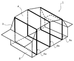
- FIG. 1 It is a disassembled perspective view of the structure for vehicles concerning one embodiment of the present invention. It is an external appearance perspective view of the vehicle structure of FIG. It is a perspective view which shows the internal structure of the structure for vehicles of FIG. It is a perspective view of the frame structure part of the structure for vehicles concerning another embodiment of the present invention.
- a vehicle structural body 1 shown in the figure forms at least a vehicle compartment outline of a vehicle, and includes a panel member comprising a floor 2 provided on the lower side, side panels 3 provided on both sides, and a roof 4 provided on the upper side. It is configured as a structural body.
- the vehicle structure 1 is circulated in a direction having a crossing angle with respect to the vehicle longitudinal direction (XY direction in FIG. 1), in the illustrated example, in a direction perpendicular to the vehicle longitudinal direction XY. (Ie, extending in a quadrangular shape so as to surround the passenger compartment), the structure includes a front portion (X side portion in FIG.
- a frame provided at the front portion of the structure is referred to as a front cross frame 5a
- a frame provided at the center portion of the structure is referred to as a center cross frame 5b
- a frame provided at the rear portion of the structure is referred to as a rear cross frame 5c.
- each of the frames 5a, 5b, and 5c is simplified so as to extend in a square shape, but for example, the upper side of the front cross frame 5a is formed to curve toward the rear side, It is also possible to form the upper part of the rear cross frame 5c so as to bend toward the front side, and at least one of the front cross frame 5a, the center cross frame 5b, and the rear cross frame 5c (particularly the upper part thereof). ) Can be formed to bend toward the inside (vehicle compartment side).
- the floor 2, the side panel 3, and the roof 4 are attached to the frames 5 a, 5 b, and 5 c provided at the three locations as described above, so that these panel members 2, 3,
- the interior surrounded by 4 is formed as a compartment 6. That is, the internal structure of the vehicle structure 1 is configured as shown in FIG.
- all of the frames 5a, 5b, and 5c are made of fiber reinforced resin, particularly carbon fiber reinforced resin, and the panel members 2, 3, and 4 are joined to the frames 5a, 5b, and 5c by, for example, adhesion.
- each frame 5a, 5b, 5c preferably includes at least reinforcing fibers, particularly carbon fibers, extending in the circumferential direction of the frame in order to increase frame rigidity.
- all the panel members of the floor 2, the side panel 3, and the roof 4 are also made of fiber reinforced resin, particularly carbon fiber reinforced resin. The entire body 1 is significantly reduced in weight.
- a vertical frame portion extending in the vertical direction (in the ZZ direction in FIG. 1) in each frame 5a, 5b, 5c is a hinge of a side door (not shown) attached to the space forming portion (3a, 3b) of the side panel 3.
- it constitutes a lock mounting base means.
- the vertical frame portion 5a1 of the front cross frame 5a constitutes a mounting base means for the front side door hinge
- the vertical frame portion 5b1 of the center cross frame 5b is a mounting base means for the front side door lock.
- the rear side door hinge mounting base means, and the vertical frame portion 5c1 of the rear cross frame 5c constitutes the rear side door lock mounting base means.
- the vertical frame portions 5a1, 5b1, 5c1 extending in the vertical direction in the respective frames 5a, 5b, 5c also constitute reinforcing means for the side panel 3.
- the horizontal frame portions 5a2, 5b2, and 5c2 extending in the vehicle width direction (the WW direction in FIG. 1) below the frames 5a, 5b, and 5c constitute reinforcing means for the floor 2.
- the lateral frame portions 5a3, 5b3, and 5c3 extending in the vehicle width direction WW above the respective frames 5a, 5b, and 5c constitute reinforcing means for the roof 4.
- the frames 5a, 5b, and 5c extending so as to surround the vehicle compartment 6 are provided at three locations of the front portion, the center portion, and the rear portion.
- the structure of the frame 5a, 5b, and 5c provided at three places is provided with the panel members of the floor 2, the side panel 3, and the roof 4, the vehicle structure is simple in structure. As a whole, it becomes possible to develop extremely high strength and rigidity.
- the lateral frame portions 5a3, 5b3, and 5c3 extending in the vehicle width direction WW above the frames 5a, 5b, and 5c are made of a material having a lower specific gravity than the other frame portions.
- the basis weight of the reinforcing fibers it is possible to set the basis weight of the reinforcing fibers to be lower than that of the other frame portions to reduce the specific gravity.
- the weight of the upper side of the vehicle structure 1 can be made relatively lower than the lower side, and the demand for lowering the center of gravity of the vehicle body can be met.
- FIG. 4 shows a frame structure portion 11 of a vehicle structure according to another embodiment of the present invention.
- the frame structure portion 11 has frames 12 a, 12 b, and 12 c that extend around the three portions of the front portion, the center portion, and the rear portion of the structure 11.
- the vehicle width direction (WW direction) left upper end of the frame 12b provided in the center portion is further the vehicle width of the frames 12a and 12c provided in the front portion and the rear portion.
- reinforcing means 13a, 13b, 13c, 13d are connected by reinforcing means 13a, 13b, 13c, 13d.
- These reinforcing means 13a, 13b, 13c, and 13d need only be able to develop a predetermined strength in the tensile direction, and may be configured as wire-like, belt-like, or string-like means.
- these reinforcing means 13a, 13b, 13c, 13d can also be made of fiber reinforced resin, particularly carbon fiber reinforced resin, and in that case, in the extending direction of the reinforcing means 13a, 13b, 13c, 13d. It is preferable that an extending reinforcing fiber is included.
- these reinforcing means 13a, 13b, 13c, and 13d are made of a material having a lower specific gravity than other parts, as in the case of the horizontal frame portions 5a3, 5b3, and 5c3 described above, a request for lowering the center of gravity of the vehicle body is desired. It becomes possible to realize the reinforcement by the reinforcing means while responding to the above.
- the reinforcing means 13a, 13b, 13c, and 13d are added, particularly when a lateral load is applied to the frame 12b provided in the center portion, the load is applied to the frame 12b provided in the center portion.
- the frames 12a and 12c provided on the front part and the rear part to which force is transmitted through the reinforcing means 13a, 13b, 13c and 13d connected as described above can also be received in a distributed manner. Thus, a larger side impact load can be received.
- the frames 12a, 12b, 12c are connected by the reinforcing means 13a, 13b, 13c, 13d, the strength and rigidity of the frame structure portion 11 as a whole against the load from the outside can be increased, It is possible to realize a structure with a smaller amount of deformation with respect to an external load and capable of removing the possibility of destruction.
- the vehicular structure according to the present invention can be applied to virtually any vehicle, and is particularly suitable for a vehicle with a strong demand for weight reduction.
Landscapes
- Engineering & Computer Science (AREA)
- Chemical & Material Sciences (AREA)
- Combustion & Propulsion (AREA)
- Transportation (AREA)
- Mechanical Engineering (AREA)
- Architecture (AREA)
- Structural Engineering (AREA)
- Body Structure For Vehicles (AREA)
Abstract
少なくとも車両の車室輪郭を形成し、フロア、サイドパネル、ルーフを含む車両用構造体において、車両前後方向に対して交差角を持つ方向に周回するように延びるフレームが、構造体のフロント部とリア部、およびフロント部とリア部の間のセンター部の3箇所にそれぞれ設けられていることを特徴とする車両用構造体。側方から大きな荷重を受けても変形を適切に抑えることのできる高い強度、剛性を備えた構造体を実現することができ、それによって車両用構造体のFRP化、FRP化を介しての軽量化が可能になる。
Description
本発明は、少なくとも車両の車室輪郭を形成する車両用構造体に関する。
少なくとも車両の車室輪郭を形成する車両用構造体として、例えば、車室の下部に設けられるベースフレームに対して、車室の前後方向中央部で車室を囲むように車両幅方向に延びるフレーム(以下、「車室を囲むように車両幅方向に延びるフレーム」をクロスフレームと言うこともある。)を設けて骨格を構成し、この骨格に、パネル状部材であるフロア、サイドパネル、ルーフなどを接合して、車室部分を形成するための構造体を構成する技術が知られている。このようなクロスフレームを用いて構成される車両用フレーム構造は、スペースフレームと呼ばれることもあり、通常は、金属製フレーム部材を接合や連結した構造に構成されている(例えば、特許文献1)。
このようなスペースフレームを採用しない車両では、通常、サイドパネルは、車室の前後方向中央部で上方に向けて延びるBピラーに接合、あるいはBピラーと一体構造に構成されているが、サイドパネルとBピラーでは、側方からの大きな荷重に対し十分に耐えることが難しいことが多く、高い耐側突性能を実現するのが難しい。この点で、上記のように車室の前後方向中央部に(センター部に)クロスフレームを備えたスペースフレームを採用した車両では、サイドパネルとBピラーによる構造に比べ、より大きな側突荷重を支えることが可能となっている。しかし、従来のスペースフレームを採用した車両では、通常、クロスフレームはセンター部のみに設けられており、サイドパネルの前部側と後部側に加わる側方からの荷重は、Aピラー(車室の前後方向前部で上方に向けて延びるピラー)やCピラー(車室の前後方向後部で上方に向けて延びるピラー)が受け持つようになっているので、これらのピラー支持構造部分では大きな荷重に十分に耐えることが難しい。そのため、側突荷重が加わる位置がセンター部から前後にずれた場合、優れた耐側突性能を実現するのが難しい。
一方、上記のようなスペースフレームを採用した構造とは別に、近年、車両の軽量化、とくに、少なくとも車両の車室輪郭を形成する車両用構造体の軽量化をはかるために、該構造体におけるパネル状部材(面状部材)をFRP(Fiber Reinforced Plastic、繊維強化プラスチック)で構成したり(例えば、特許文献1)、該構造体のフレーム部材をリング状や円弧状の特殊形状の部材に構成し、該フレーム部材をFRPで構成する技術が提案されている(例えば、特許文献2、3)。
しかし、特許文献1では、面状部材のFRP化のみが示されているが、仮にサイドパネルをFRP化した場合には、荷重集中が発生しやすいドアのヒンジまたはロックの取り付け部分をFRP化したサイドパネルに設ける場合のパネル構造が複雑になり、また、それらの部分に必要な強度を考慮した上での構造設計が難しくなる。
また、特許文献2、3では、特殊形状のフレーム部材を特殊な形態で配置する構造が開示されているだけであり、通常の一般的な形状の車室を形成することや、フレーム構造体とパネル状部材との接合等に関しては考慮されていない。そのため、特許文献2、3に開示されているような構造を、一般的な形態の車両に適用することはできない。
そこで本発明の課題は、上記のような現状に鑑み、少なくとも車両の車室輪郭を形成する車両用構造体のフレーム構造体部分に十分に高い耐荷重性能を付与し、それによって構造体の少なくとも主要構成部分を容易にFRP化することができ、構造体全体の軽量化の促進が可能な車両用構造体を提供することにある。
また、本発明の別の課題は、荷重集中が発生しやすいドアのヒンジまたはロックの取り付け部分を、高い強度、剛性を確保しつつ容易に効率よく構造体中に構成できるようにした車両用構造体を提供することにある。
本発明のさらに別の課題は、望ましくは、側突時等に加わる大きな荷重に対し高い耐変形性能を有する構造を、車体の低重心化の要望を阻害することなく容易に実現できる車両用構造体を提供することにある。
上記課題を解決するために、本発明に係る車両用構造体は、少なくとも車両の車室輪郭を形成し、フロア、サイドパネル、ルーフを含む車両用構造体において、車両前後方向に対して交差角を持つ方向に(例えば、車両前後方向に対して直交する方向に)周回するように延びるフレームが、構造体のフロント部とリア部、およびフロント部とリア部の間のセンター部の3箇所にそれぞれ設けられていることを特徴とするものからなる。
このような本発明に係る車両用構造体においては、従来のセンター部のみにクロスフレームが設けられたスペースフレームに比べ、車両前後方向に対して交差角を持つ方向に周回するように延びるフレーム(つまり、従来のクロスフレームと同様のフレーム)が、構造体のフロント部とリア部、およびセンター部の3箇所にそれぞれ設けられているので、従来センター部のクロスフレームと前部側のAピラーや後部側のBピラーで受け持たれていた側方からの荷重が、センター部のフレームに加え、フロント部やリア部に設けられ周回するように延びるフレームでも受け持つことができるようになる。これら各フレームは周回するように延びるフレームであるから、単に上方に向けて延びるピラーよりも強度、剛性がはるかに高い。その結果、センター部以外でも大きな側方からの荷重を受け持つことができるようになり、これらのフレームによって支持されるサイドパネルの全面部位にわたって十分に高い耐側突性能を発揮できるようになる。また、これら3箇所に設けられたフレームを備えた骨格に対し、フロア、サイドパネル、ルーフのパネル部材が設けられることになるので、フレーム骨格と各パネル部材が互いに支持し合うとともに互いに変形を抑制し合い、車両用構造体全体としても高い強度、剛性が発現される。さらに、上記3箇所に設けられたフレームは、単純な周回構造を有していればよいので、容易に高い強度、剛性を発現する構造に構成できるとともに、要求に応じて、これら高い強度、剛性を維持しつつ容易にFRP化することも可能になる。そして、各フレームに高い強度、剛性を持たせることにより、各フレームの縦フレーム部に、荷重集中の発生しやすいドアのヒンジやロックの取り付け部分を配置することが可能になり、サイドパネルにドアのヒンジやロックの取り付け部分を配置する必要が無くなって、各フレームのFRP化の容易化に加え、サイドパネル等のパネル部材のFRP化に際しての構造設計も容易化される。その結果、少なくとも車両用構造体の主要構成部分を、望ましくは全体を、容易にFRP化できるようになり、車両用構造体の大幅な軽量化を実現できる。
上述の如く、本発明に係る車両用構造体においては、上記3カ所に設けられた各フレームにおける上下方向に延びる縦フレーム部がサイドドアのヒンジまたはロックの取り付けベース手段を構成している構造を採用できる。センター部におけるフレームの縦フレーム部には、前部側サイドドアのロックの取り付けベース手段と後部側サイドドアのヒンジの取り付けベース手段の両方を構成できる。
また、各フレームにおける上下方向に延びる縦フレーム部が上記サイドパネルの補強手段を構成している構造とすることもできる。また、各フレームの下部で車両幅方向に延びる横フレーム部が上記フロアの補強手段を構成している構造とすることもできる。さらに、各フレームの上部で車両幅方向に延びる横フレーム部が上記ルーフの補強手段を構成している構造とすることもできる。
また、本発明においては、上記センター部に設けられたフレームの車両幅方向左上端が、上記フロント部または/およびリア部に設けられたフレームの車両幅方向右上端と、上記センター部に設けられたフレームの車両幅方向右上端が、上記フロント部または/およびリア部に設けられたフレームの車両幅方向左上端と、それぞれ、引張方向に強度を発現する補強手段で連結されている構造を採用できる。このような構造においては、センター部に設けられたフレームに側方からの荷重が加わった際、その荷重をセンター部に設けられたフレーム自体で受けるとともに、上記のように連結された補強手段を介して力が伝達されるフロント部または/およびリア部に設けられたフレームでも分散して受けることができるようになり、より大きな側突荷重を受けることができるようになる。また、補強手段による連結構造により、フレーム構造体全体としての強度、剛性も高められ、荷重に対してより変形量の少ない、破壊のおそれを除去した構造の実現が可能になる。
また、本発明に係る車両用構造体において、軽量化のためには、各部位が極力繊維強化樹脂(FRP)で構成されていることが好ましい。例えば、上記フロント部、リア部、センター部に設けられたフレームの少なくとも一つが繊維強化樹脂で構成されていることが好ましく、これらフレームの全てが繊維強化樹脂で構成されていることがより好ましい。
この場合、繊維強化樹脂の強化繊維としては、高い強度、剛性を容易に実現できるとともにそれら特性の設計が容易な炭素繊維を含むことが好ましい。もちろん、ガラス繊維やアラミド繊維などの他の強化繊維を使用することも可能であり、2種以上の強化繊維を併用することも可能である。また、繊維強化樹脂のマトリックス樹脂としては、熱可塑性樹脂、熱硬化性樹脂のいずれも使用可能であり、量産性、成形のしやすさを考慮するならば、熱可塑性樹脂がより好ましい。
また、本発明においては、上記フロント部、リア部、センター部に設けられたフレームの少なくとも一つが金属で構成されている構造とすることも可能である。金属でフレームを構成すると、繊維強化樹脂で構成する場合に比べて重量的には不利になるが、車両用構造体の部位や車種によっては、少なくともいずれかのフレームを金属で構成する方が望ましい場合もあり得るので、そのような場合には金属製フレームを使用すればよい。
パネル部材についても同様である。すなわち、上記フロア、サイドパネル、ルーフの少なくとも一つが繊維強化樹脂で構成されていることが好ましく、軽量化の観点からは、これらフレームの全てが繊維強化樹脂で構成されていることがより好ましい。
また、本発明においては、上記各フレームの上部で車両幅方向に延びる横フレーム部が、他のフレーム部分よりも低比重の材料で構成されていることが好ましい。また、上記補強手段が、他の部品よりも低比重の材料で構成されていることが好ましい。このような構造においては、車両用構造体の上部側の重量を下部側に対し相対的により低くすることが可能になるので、車体の低重心化の要望がある場合、それに応えることが可能になる。換言すれば、車体の低重心化の要望を阻害することなく、上述の如く側突荷重等に対する高い耐変形性能を有する車両用構造体の実現が可能となる。
このように、本発明に係る車両用構造体によれば、周回するように延びるフレームを、構造体のフロント部、リア部、センター部の3箇所にそれぞれ設けることで、側方から大きな荷重を受けても変形を適切に抑えることのできる高い強度、剛性を備えた構造体を実現することができ、それによって車両用構造体のFRP化、FRP化を介しての軽量化が可能になる。
また、上記のように3箇所に設けられたフレームにドアのヒンジやロックの取り付け部分を構成することが可能になり、パネル部材での構成を不要化して、結果的に構造体のFRP化の促進に寄与できる。
さらに、横フレーム部や補強手段などの構成を工夫することで、車体の低重心化を阻害することなく、全体として高強度、高剛性の構造体を実現できる。
以下に、本発明の実施の形態を、図面を参照しながら説明する。
図1~3は、本発明の一実施態様に係る車両用構造体を示している。図に示す車両用構造体1は、少なくとも車両の車室輪郭を形成し、下部側に設けられるフロア2、両側に設けられるサイドパネル3、上部側に設けられるルーフ4からなるパネル部材を含む車両用構造体として構成されている。この車両用構造体1には、車両前後方向(図1のX-Y方向)に対して交差角を持つ方向に、図示例では、車両前後方向X-Yに対して直交する方向に、周回するように延びる(つまり、車室部分を囲むように四角状に延びる)フレームが、構造体のフロント部(図1のX側部分)とリア部(図1のY側部分)、およびフロント部とリア部の間のセンター部の3箇所にそれぞれ設けられている。以下、構造体のフロント部に設けられたフレームをフロントクロスフレーム5a、構造体のセンター部に設けられたフレームをセンタークロスフレーム5b、構造体のリア部に設けられたフレームをリアクロスフレーム5cと呼ぶこともある。なお、図示例では、各フレーム5a、5b、5cは四角状に延びるように簡略化して示してあるが、例えば、フロントクロスフレーム5aの上部側をリア側に向けて湾曲するように形成し、リアクロスフレーム5cの上部側をフロント側に向けて湾曲するように形成することも可能であり、さらに、フロントクロスフレーム5a、センタークロスフレーム5b、リアクロスフレーム5cの少なくともいずれか(とくにそれらの上部)を、内側(車室側)に向けて湾曲するように形成することも可能である。
図1~3は、本発明の一実施態様に係る車両用構造体を示している。図に示す車両用構造体1は、少なくとも車両の車室輪郭を形成し、下部側に設けられるフロア2、両側に設けられるサイドパネル3、上部側に設けられるルーフ4からなるパネル部材を含む車両用構造体として構成されている。この車両用構造体1には、車両前後方向(図1のX-Y方向)に対して交差角を持つ方向に、図示例では、車両前後方向X-Yに対して直交する方向に、周回するように延びる(つまり、車室部分を囲むように四角状に延びる)フレームが、構造体のフロント部(図1のX側部分)とリア部(図1のY側部分)、およびフロント部とリア部の間のセンター部の3箇所にそれぞれ設けられている。以下、構造体のフロント部に設けられたフレームをフロントクロスフレーム5a、構造体のセンター部に設けられたフレームをセンタークロスフレーム5b、構造体のリア部に設けられたフレームをリアクロスフレーム5cと呼ぶこともある。なお、図示例では、各フレーム5a、5b、5cは四角状に延びるように簡略化して示してあるが、例えば、フロントクロスフレーム5aの上部側をリア側に向けて湾曲するように形成し、リアクロスフレーム5cの上部側をフロント側に向けて湾曲するように形成することも可能であり、さらに、フロントクロスフレーム5a、センタークロスフレーム5b、リアクロスフレーム5cの少なくともいずれか(とくにそれらの上部)を、内側(車室側)に向けて湾曲するように形成することも可能である。
上記のように3箇所に設けられたフレーム5a、5b、5cに、図2に示すように、フロア2、サイドパネル3、ルーフ4が接合等により取り付けられることにより、これらパネル部材2、3、4で囲まれた内部が車室6として形成される。つまり、車両用構造体1の内部構造は、図3に示すように構成されている。
本実施態様では、フレーム5a、5b、5cの全てが繊維強化樹脂、とくに炭素繊維強化樹脂で構成されており、これらフレーム5a、5b、5cに各パネル部材2、3、4が例えば接着によって接合されている。この場合、各フレーム5a、5b、5cは、フレーム剛性を高めるために、少なくとも、フレームの周回方向に延在する強化繊維、とくに炭素繊維を含んでいることが好ましい。また、本本実施態様では、フロア2、サイドパネル3、ルーフ4の各パネル部材の全ても、繊維強化樹脂、とくに炭素繊維強化樹脂で構成されており、金属製の場合に比べて、車両用構造体1の全体が大幅に軽量化されている。
各フレーム5a、5b、5cにおける上下方向に(図1のZ-Z方向に)延びる縦フレーム部は、サイドパネル3の空間形成部(3a、3b)に取り付けられるサイドドア(図示略)のヒンジまたはロックの取り付けベース手段を構成している。例えば、フロントクロスフレーム5aの縦フレーム部5a1は、前側のサイドドアのヒンジの取り付けベース手段を構成しており、センタークロスフレーム5bの縦フレーム部5b1は、前側のサイドドアのロックの取り付けベース手段と後側のサイドドアのヒンジの取り付けベース手段を構成しており、リアクロスフレーム5cの縦フレーム部5c1は、後側のサイドドアのロックの取り付けベース手段を構成している。
また、各フレーム5a、5b、5cにおける上下方向に延びる縦フレーム部5a1、5b1、5c1は、上記サイドパネル3の補強手段も構成している。また、各フレーム5a、5b、5cの下部で車両幅方向(図1のW-W方向)に延びる横フレーム部5a2、5b2、5c2は、上記フロア2の補強手段を構成している。さらに、各フレーム5a、5b、5cの上部で車両幅方向W-Wに延びる横フレーム部5a3、5b3、5c3は、上記ルーフ4の補強手段を構成している。
このように構成された車両用構造体1においては、車室6を囲むように延びるフレーム5a、5b、5cがフロント部、センター部、リア部の3箇所に設けられているので、従来のセンター部のクロスフレームと前部側のAピラーや後部側のBピラーで側方からの荷重を受け持つようにしていた構造に比べ、より大きな側方からの荷重を受け持つことができるようになり、十分に高い耐側突性能を発揮できるようになる。また、3箇所に設けられたフレーム5a、5b、5cによるフレーム骨格にフロア2、サイドパネル3、ルーフ4のパネル部材が設けられた構造となるので、簡単な構造でありながら、車両用構造体1全体として極めて高い強度、剛性の発現が可能となる。さらに、各フレーム5a、5b、5cの縦フレーム部5a1、5b1、5c1に、荷重集中の発生しやすいドアのヒンジやロックの取り付け部分を配置することが可能になり、サイドパネル3にドアのヒンジやロックの取り付け部分を配置する必要が無くなって、各フレーム5a、5b、5cのFRP化が容易化されているとともに、サイドパネル3等のパネル部材のFRP化も容易化されている。その結果、少なくとも車両用構造体1の主要構成部分を、望ましくは全体を、容易にFRP化できるようになり、車両用構造体1全体の望ましい強度、剛性が確保されつつ、車両用構造体1の大幅な軽量化が達成される。
上記車両用構造体1においては、上記各フレーム5a、5b、5cの上部で車両幅方向W-Wに延びる横フレーム部5a3、5b3、5c3を、他のフレーム部分よりも低比重の材料で構成することが可能である。例えば、横フレーム部5a3、5b3、5c3においては、他のフレーム部分よりも強化繊維の目付を低く設定して低比重することが可能である。このような構造においては、車両用構造体1の上部側の重量を下部側に対し相対的により低くすることが可能になり、車体の低重心化の要望に応えることが可能になる。
図4は、本発明の別の実施態様に係る車両用構造体のフレーム構造体部分11を示している。フレーム構造体部分11には、図1に示した実施態様と同様に、構造体11のフロント部と、センター部と、リア部の3箇所に、周回するように延びるフレーム12a、12b、12cが設けられており、本実施態様では、さらに、センター部に設けられたフレーム12bの車両幅方向(W-W方向)左上端が、フロント部およびリア部に設けられたフレーム12a、12cの車両幅方向右上端と、センター部に設けられたフレーム12bの車両幅方向右上端が、フロント部およびリア部に設けられたフレーム12a、12cの車両幅方向左上端と、それぞれ、引張方向に強度を発現する補強手段13a、13b、13c、13dで連結されている.これら補強手段13a、13b、13c、13dは、引張方向に所定の強度を発現できればよく、ワイヤー状、帯状、紐状の手段に構成されていればよい。また、これら補強手段13a、13b、13c、13dもまた、繊維強化樹脂、とくに炭素繊維強化樹脂で構成することができ、その場合には、補強手段13a、13b、13c、13dの延在方向に延びる強化繊維が含まれていることが好ましい。また、これら補強手段13a、13b、13c、13dを他の部品よりも低比重の材料で構成すれば、前述の横フレーム部5a3、5b3、5c3における場合と同様に、車体の低重心化の要望に応えつつ、補強手段による補強を実現することが可能になる。
このように補強手段13a、13b、13c、13dを付加した構造においては、とくにセンター部に設けられたフレーム12bに側方からの荷重が加わった際、その荷重をセンター部に設けられたフレーム12b自体で受けるとともに、上記のように連結された補強手段13a、13b、13c、13dを介して力が伝達されるフロント部およびリア部に設けられたフレーム12a、12cでも分散して受けることができるようになって、より大きな側突荷重を受けることができるようになる。また、補強手段13a、13b、13c、13dにより各フレーム12a、12b、12cが連結された構造となるので、外部からの荷重に対してフレーム構造体部分11全体としての強度、剛性も高められ、外部荷重に対してより変形量の少ない、破壊のおそれを除去可能な構造の実現が可能になる。
本発明に係る車両用構造体は、実質的にあらゆる車両に適用でき、とくに、軽量化の要求の強い車両に好適である。
1 車両用構造体
2 フロア
3 サイドパネル
3a、3b サイドパネルの空間形成部
4 ルーフ
5a、5b、5c フレーム
5a1、5b1、5c1 縦フレーム部
5a2、5b2、5c2 下部の横フレーム部
5a3、5b3、5c3 上部の横フレーム部
6 車室
11 フレーム構造体部分
12a、12b、12c フレーム
13a、13b、13c、13d 補強手段
2 フロア
3 サイドパネル
3a、3b サイドパネルの空間形成部
4 ルーフ
5a、5b、5c フレーム
5a1、5b1、5c1 縦フレーム部
5a2、5b2、5c2 下部の横フレーム部
5a3、5b3、5c3 上部の横フレーム部
6 車室
11 フレーム構造体部分
12a、12b、12c フレーム
13a、13b、13c、13d 補強手段
Claims (12)
- 少なくとも車両の車室輪郭を形成し、フロア、サイドパネル、ルーフを含む車両用構造体において、
車両前後方向に対して交差角を持つ方向に周回するように延びるフレームが、構造体のフロント部とリア部、およびフロント部とリア部の間のセンター部の3箇所にそれぞれ設けられていることを特徴とする車両用構造体。 - 各フレームにおける上下方向に延びる縦フレーム部がサイドドアのヒンジまたはロックの取り付けベース手段を構成している、請求項1に記載の車両用構造体。
- 各フレームにおける上下方向に延びる縦フレーム部が前記サイドパネルの補強手段を構成している、請求項1または2に記載の車両用構造体。
- 各フレームの下部で車両幅方向に延びる横フレーム部が前記フロアの補強手段を構成している、請求項1~3のいずれかに記載の車両用構造体。
- 各フレームの上部で車両幅方向に延びる横フレーム部が前記ルーフの補強手段を構成している、請求項1~4のいずれかに記載の車両用構造体。
- 前記センター部に設けられたフレームの車両幅方向左上端が、前記フロント部または/およびリア部に設けられたフレームの車両幅方向右上端と、前記センター部に設けられたフレームの車両幅方向右上端が、前記フロント部または/およびリア部に設けられたフレームの車両幅方向左上端と、それぞれ、引張方向に強度を発現する補強手段で連結されている、請求項1~5のいずれかに記載の車両用構造体。
- 前記フロント部、リア部、センター部に設けられたフレームの少なくとも一つが繊維強化樹脂で構成されている、請求項1~6のいずれかに記載の車両用構造体。
- 前記繊維強化樹脂の強化繊維として炭素繊維を含む、請求項7に記載の車両用構造体。
- 前記フロント部、リア部、センター部に設けられたフレームの少なくとも一つが金属で構成されている、請求項1~8のいずれかに記載の車両用構造体。
- 前記フロア、サイドパネル、ルーフの少なくとも一つが繊維強化樹脂で構成されている、請求項1~9のいずれかに記載の車両用構造体。
- 前記各フレームの上部で車両幅方向に延びる横フレーム部が、他のフレーム部分よりも低比重の材料で構成されている、請求項5~10のいずれかに記載の車両用構造体。
- 前記補強手段が、他の部品よりも低比重の材料で構成されている、請求項6~11のいずれかに記載の車両用構造体。
Priority Applications (3)
| Application Number | Priority Date | Filing Date | Title |
|---|---|---|---|
| EP12876789.4A EP2851271A4 (en) | 2012-05-16 | 2012-05-16 | VEHICLE STRUCTURE BODY |
| PCT/JP2012/062459 WO2013171852A1 (ja) | 2012-05-16 | 2012-05-16 | 車両用構造体 |
| JP2014515403A JPWO2013171852A1 (ja) | 2012-05-16 | 2012-05-16 | 車両用構造体 |
Applications Claiming Priority (1)
| Application Number | Priority Date | Filing Date | Title |
|---|---|---|---|
| PCT/JP2012/062459 WO2013171852A1 (ja) | 2012-05-16 | 2012-05-16 | 車両用構造体 |
Publications (1)
| Publication Number | Publication Date |
|---|---|
| WO2013171852A1 true WO2013171852A1 (ja) | 2013-11-21 |
Family
ID=49583297
Family Applications (1)
| Application Number | Title | Priority Date | Filing Date |
|---|---|---|---|
| PCT/JP2012/062459 Ceased WO2013171852A1 (ja) | 2012-05-16 | 2012-05-16 | 車両用構造体 |
Country Status (3)
| Country | Link |
|---|---|
| EP (1) | EP2851271A4 (ja) |
| JP (1) | JPWO2013171852A1 (ja) |
| WO (1) | WO2013171852A1 (ja) |
Families Citing this family (1)
| Publication number | Priority date | Publication date | Assignee | Title |
|---|---|---|---|---|
| EP2865582A4 (en) * | 2012-06-22 | 2016-02-17 | Toray Industries | PRFV ELEMENT |
Citations (9)
| Publication number | Priority date | Publication date | Assignee | Title |
|---|---|---|---|---|
| JPS4718226U (ja) * | 1971-03-31 | 1972-10-31 | ||
| JPS6288676A (ja) * | 1985-10-15 | 1987-04-23 | Honda Motor Co Ltd | 車体支持構造体 |
| JP2001515822A (ja) * | 1997-09-08 | 2001-09-25 | ピブコ インダストリーズ アーエス | 車両用の装置およびその装置を製造する方法 |
| JP2004338419A (ja) * | 2003-05-12 | 2004-12-02 | Nissan Motor Co Ltd | 車両骨格構造 |
| JP2009202828A (ja) * | 2008-02-29 | 2009-09-10 | Mazda Motor Corp | 車体の製造方法および製造ライン |
| JP2010023706A (ja) | 2008-07-22 | 2010-02-04 | Toyota Motor Corp | 車体構造 |
| JP2011037313A (ja) * | 2009-08-07 | 2011-02-24 | Hitachi Ltd | スペースフレーム構造を有する自動車 |
| JP2011516329A (ja) | 2008-04-04 | 2011-05-26 | ゴードン・マレー・デザイン・リミテッド | 車両シャーシ |
| JP2011245912A (ja) | 2010-05-24 | 2011-12-08 | Toyota Central R&D Labs Inc | 車体構造 |
-
2012
- 2012-05-16 WO PCT/JP2012/062459 patent/WO2013171852A1/ja not_active Ceased
- 2012-05-16 JP JP2014515403A patent/JPWO2013171852A1/ja active Pending
- 2012-05-16 EP EP12876789.4A patent/EP2851271A4/en not_active Withdrawn
Patent Citations (9)
| Publication number | Priority date | Publication date | Assignee | Title |
|---|---|---|---|---|
| JPS4718226U (ja) * | 1971-03-31 | 1972-10-31 | ||
| JPS6288676A (ja) * | 1985-10-15 | 1987-04-23 | Honda Motor Co Ltd | 車体支持構造体 |
| JP2001515822A (ja) * | 1997-09-08 | 2001-09-25 | ピブコ インダストリーズ アーエス | 車両用の装置およびその装置を製造する方法 |
| JP2004338419A (ja) * | 2003-05-12 | 2004-12-02 | Nissan Motor Co Ltd | 車両骨格構造 |
| JP2009202828A (ja) * | 2008-02-29 | 2009-09-10 | Mazda Motor Corp | 車体の製造方法および製造ライン |
| JP2011516329A (ja) | 2008-04-04 | 2011-05-26 | ゴードン・マレー・デザイン・リミテッド | 車両シャーシ |
| JP2010023706A (ja) | 2008-07-22 | 2010-02-04 | Toyota Motor Corp | 車体構造 |
| JP2011037313A (ja) * | 2009-08-07 | 2011-02-24 | Hitachi Ltd | スペースフレーム構造を有する自動車 |
| JP2011245912A (ja) | 2010-05-24 | 2011-12-08 | Toyota Central R&D Labs Inc | 車体構造 |
Non-Patent Citations (1)
| Title |
|---|
| See also references of EP2851271A4 * |
Also Published As
| Publication number | Publication date |
|---|---|
| EP2851271A1 (en) | 2015-03-25 |
| JPWO2013171852A1 (ja) | 2016-01-07 |
| EP2851271A4 (en) | 2015-12-23 |
Similar Documents
| Publication | Publication Date | Title |
|---|---|---|
| JP6128334B2 (ja) | 車両の後部車体構造 | |
| JP4853101B2 (ja) | 自動車の前部車体構造 | |
| US20140084635A1 (en) | Vehicle | |
| CN107487370B (zh) | 车身侧围结构、c柱加强板和车辆 | |
| JPWO2014034586A1 (ja) | 車両用ルーフ構造体 | |
| EP2623399A1 (en) | Vehicle body structure | |
| JP7106975B2 (ja) | 車両の車体構造 | |
| JP2008279906A (ja) | 車体後部構造 | |
| JPWO2015037444A1 (ja) | 自動車の車体構造 | |
| WO2016199500A1 (ja) | 車体後部構造 | |
| US20140084629A1 (en) | Steering Support Member | |
| JP2013112075A (ja) | 車体側部構造 | |
| JP4556674B2 (ja) | 車両の側部車体構造 | |
| CN110505995B (zh) | 车身前部结构 | |
| JP2013006519A (ja) | 車体上部構造 | |
| KR20200092526A (ko) | 차량용 도어 | |
| JP2010247610A (ja) | 車体後部構造 | |
| JP6176227B2 (ja) | 車両の前部車体構造 | |
| JP2007261481A (ja) | 車両の側部車体構造 | |
| JP6362009B2 (ja) | 車体後部構造 | |
| JP5830452B2 (ja) | 自動車の車体後部構造 | |
| WO2013171852A1 (ja) | 車両用構造体 | |
| JP6237669B2 (ja) | 車両の上部車体構造 | |
| JP6016246B2 (ja) | 自動車の車体構造 | |
| JP2009179295A (ja) | 自動車の後部フロア構造 |
Legal Events
| Date | Code | Title | Description |
|---|---|---|---|
| 121 | Ep: the epo has been informed by wipo that ep was designated in this application |
Ref document number: 12876789 Country of ref document: EP Kind code of ref document: A1 |
|
| ENP | Entry into the national phase |
Ref document number: 2014515403 Country of ref document: JP Kind code of ref document: A |
|
| NENP | Non-entry into the national phase |
Ref country code: DE |
|
| WWE | Wipo information: entry into national phase |
Ref document number: 2012876789 Country of ref document: EP |