WO2013172017A1 - Cooling control device and cooling control method for internal combustion engine - Google Patents
Cooling control device and cooling control method for internal combustion engine Download PDFInfo
- Publication number
- WO2013172017A1 WO2013172017A1 PCT/JP2013/003068 JP2013003068W WO2013172017A1 WO 2013172017 A1 WO2013172017 A1 WO 2013172017A1 JP 2013003068 W JP2013003068 W JP 2013003068W WO 2013172017 A1 WO2013172017 A1 WO 2013172017A1
- Authority
- WO
- WIPO (PCT)
- Prior art keywords
- coolant
- passage
- combustion engine
- internal
- internal combustion
- Prior art date
- Legal status (The legal status is an assumption and is not a legal conclusion. Google has not performed a legal analysis and makes no representation as to the accuracy of the status listed.)
- Ceased
Links
Images


Classifications
-
- F—MECHANICAL ENGINEERING; LIGHTING; HEATING; WEAPONS; BLASTING
- F01—MACHINES OR ENGINES IN GENERAL; ENGINE PLANTS IN GENERAL; STEAM ENGINES
- F01P—COOLING OF MACHINES OR ENGINES IN GENERAL; COOLING OF INTERNAL-COMBUSTION ENGINES
- F01P7/00—Controlling of coolant flow
- F01P7/14—Controlling of coolant flow the coolant being liquid
- F01P7/16—Controlling of coolant flow the coolant being liquid by thermostatic control
- F01P7/165—Controlling of coolant flow the coolant being liquid by thermostatic control characterised by systems with two or more loops
-
- F—MECHANICAL ENGINEERING; LIGHTING; HEATING; WEAPONS; BLASTING
- F01—MACHINES OR ENGINES IN GENERAL; ENGINE PLANTS IN GENERAL; STEAM ENGINES
- F01P—COOLING OF MACHINES OR ENGINES IN GENERAL; COOLING OF INTERNAL-COMBUSTION ENGINES
- F01P11/00—Component parts, details, or accessories not provided for in, or of interest apart from, groups F01P1/00 - F01P9/00
- F01P11/14—Indicating devices; Other safety devices
- F01P11/16—Indicating devices; Other safety devices concerning coolant temperature
-
- F—MECHANICAL ENGINEERING; LIGHTING; HEATING; WEAPONS; BLASTING
- F01—MACHINES OR ENGINES IN GENERAL; ENGINE PLANTS IN GENERAL; STEAM ENGINES
- F01P—COOLING OF MACHINES OR ENGINES IN GENERAL; COOLING OF INTERNAL-COMBUSTION ENGINES
- F01P7/00—Controlling of coolant flow
- F01P7/14—Controlling of coolant flow the coolant being liquid
- F01P7/16—Controlling of coolant flow the coolant being liquid by thermostatic control
- F01P7/167—Controlling of coolant flow the coolant being liquid by thermostatic control by adjusting the pre-set temperature according to engine parameters, e.g. engine load, engine speed
-
- F—MECHANICAL ENGINEERING; LIGHTING; HEATING; WEAPONS; BLASTING
- F01—MACHINES OR ENGINES IN GENERAL; ENGINE PLANTS IN GENERAL; STEAM ENGINES
- F01P—COOLING OF MACHINES OR ENGINES IN GENERAL; COOLING OF INTERNAL-COMBUSTION ENGINES
- F01P2031/00—Fail safe
- F01P2031/32—Deblocking of damaged thermostat
Definitions
- the present invention relates to a cooling control device and a cooling control method for cooling an internal combustion engine such as a car engine.
- a cooling control device for cooling an internal combustion engine such as a car engine has a failure in a control system configured to control the flow of coolant, the internal combustion engine (engine) overheats.
- Japanese Patent No. 3794783 discloses a technique of releasing connection of a control drive valve between a motor and a flow passage control valve by using a clutch mechanism when an abnormal temperature of coolant in the internal combustion engine is detected. This technique prevents the engine from overheating by forcibly opening the flow passage control valve to promote the circulation of the coolant.
- An object of the present invention is to provide a cooling control device and a cooling control method for an internal combustion engine which, when circuit switching fails in connecting an internal coolant passage in the internal combustion engine and an external coolant passage passing through the radiator to each other, can send the coolant inside the internal coolant passage to the radiator, and which has no increase in the number of parts, nor cost increase accordingly.
- a cooling control device of an internal combustion engine of the present invention is provided with: a branching passage configured to send coolant in an internal coolant passage to one of external coolant passages which passes through a radiator, when circuit switching means has a failure and fails in circuit switching of connecting the internal coolant passage and the external coolant passage passing through the radiator to each other; and a wax-type thermostat provided in the branching passage and configured to open the branching passage when the internal combustion engine is excessively heated.
- a temperature sensing portion of the wax-type thermostat is provided near an inlet of an external coolant passage configured to send the coolant in the internal coolant passage to a throttle chamber.
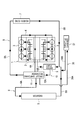
- Fig. 1 is a cooling circuit diagram of an internal combustion engine of an embodiment.
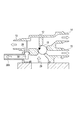
- Fig. 2 is a cross-sectional view of a circuit switching mechanism in Fig. 1.
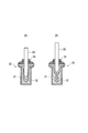
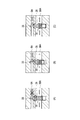
- Fig. 3 is a cross-sectional view of a wax-type thermostat provided in the circuit switching mechanism of Fig. 1, and part (A) shows an operation state at a low temperature and part (B) shows an operation state at a high temperature.
- Fig. 4 is a graph showing temperature rise of coolant in a cooling control device of the internal combustion engine of the embodiment.
- Fig. 5 is a cooling circuit diagram of the internal combustion engine in another example of the embodiment.
- Fig. 6 is a cross-sectional view of the circuit switching mechanism used in the cooling circuit of Fig. 5.
- Fig. 1 is a cooling circuit diagram of an internal combustion engine of an embodiment.
- Fig. 2 is a cross-sectional view of a circuit switching mechanism in Fig. 1.
- Fig. 3 is a cross-sectional view of a wax-
- part (A) shows a state before open operation
- part (B) shows a state where the open operation is started
- part (C) shows an open operation state.
- Fig. 1 shows a cooling circuit diagram of an internal combustion engine.
- an internal coolant passage 4 in which coolant circulates through a cylinder block 2 and cylinder heads 3 is formed in the internal combustion engine 1 of a car engine or the like.
- Multiple external coolant passages are connected to the internal coolant passage 4.
- the external coolant passages includes a radiator circuit 6 (6A, 6B) running through a radiator 5 which is a heat exchanger, a heater circuit 8 (8A, 8B) running through a heater core 7, and a bypass circuit 10 (10A, 10B) running through a water pump 9.
- a radiator circuit 6 (6A, 6B) running through a radiator 5 which is a heat exchanger
- a heater circuit 8 (8A, 8B) running through a heater core 7
- a bypass circuit 10 (10A, 10B) running through a water pump 9.
- water is used as the coolant.
- the radiator circuit 6 includes a radiator circuit 6A connecting the radiator 5 and a circuit switching mechanism 11 as well as the radiator circuit 6B connecting the radiator 5 and the water pump 9, the circuit switching mechanism 11 being a circuit switching means connected to an outlet 4A of the internal coolant passage 4.
- the radiator circuit 6 sends the coolant heated in the internal coolant passage 4 formed in the internal combustion engine 1 to the radiator 5 and the heated coolant is cooled in the radiator 5 by performing heat exchange with air. Then, the radiator circuit 6 returns the cooled coolant to the internal coolant passage 4.
- the heater circuit 8 includes a heater circuit 8A connecting the circuit switching mechanism 11 and the heater core 7 as well as a heater circuit 8B connecting the heater core 7 and the water pump 9.
- the heater circuit 8 causes the coolant heated in the internal coolant passage 4 formed in the internal combustion engine 1 to disperse heat in the heater core 7 and then returns the coolant after the heat dispersion to the internal coolant passage 4.
- the bypass circuit 10 includes a bypass circuit 10A connecting the circuit switching mechanism 11 and a water pump 9 as well as a bypass circuit 10B connecting the water pump 9 and the internal coolant passage 4.
- the bypass circuit 10 returns the coolant in the internal coolant passage 4 formed in the internal combustion engine 1 to the internal coolant passage 4 without causing the coolant to flow through the radiator circuit 6.
- Fig. 2 shows a cross-sectional view of a main portion of the circuit switching mechanism 11.
- the circuit switching mechanism 11 includes a body 12 in which flow passages connected respectively to the internal coolant passage 4, the radiator circuit 6, the heater circuit 8, and the bypass circuit 10 are formed.
- a radiator hose connection port 13 for connection with the radiator circuit 6, a heater hose connection port 14 for connection with the heater circuit 8, and a bypass hose connection port 15 for connection with the bypass circuit 10 are provided on side surfaces of the body 12.
- the body 12 is provided therein with a circuit switching means 16 for switching the circuits by connecting or disconnecting the internal coolant passage 4 to or from each of the radiator circuit 6, the heater circuit 8, and the bypass circuit 10 to cause the coolant flowing into the body from the outlet 4A of the internal coolant passage 4 to flow to one of the circuits as needed.
- the circuit switching means 16 is schematically illustrated.
- the body 12 is provided therein with a branching passage 28 which is a flow passage separate from the flow passage which causes the coolant flowing in from a coolant introduction port 29 formed in a body lower portion and connected to the outlet 4A of the internal coolant passage 4 to flow to the radiator hose connection port 13.
- the branching passage 28 is configured such that the coolant introduced from the coolant introduction port 29 in the body lower portion flows to the radiator hose connection port 13 without passing through the circuit switching means 16.
- the branching passage 28 is provided with a wax-type thermostat 30 which opens the branching passage 28 when the internal combustion engine 1 is excessively heated.
- a wax-type thermostat 30 which opens the branching passage 28 when the internal combustion engine 1 is excessively heated.
- the wax-type thermostat 30 when wax 32 encapsulated in a metal container 31 is heated, the wax 32 changes from the solid phase to the liquid phase and the volume thereof increases, thereby pushing a piston 33 upward.
- the wax-type thermostat 30 when the wax 32 is cooled and changes from the liquid phase to the solid phase, the volume thereof decreases and this causes the piston 33 to retreat into the metal container 31 and return to its original state.
- a front end portion of the piston 33 is fixed to an inner wall surface of the radiator hose connection port 13.
- the piston 33 has a shape not blocking the flow of the coolant flowing from the circuit switching means 16 to the radiator hose connection port 13.
- a sealing portion 34 provided at a front end of the metal container 31 has a shape blocking an outlet of the branching passage 28 at a normal temperature.
- the wax-type thermostat 30 when the excessive heating state of the internal combustion engine 1 is resolved and the coolant flowing in the internal coolant passage 4 is in a state of the normal temperature which is a low temperature, the wax 32 changes from the liquid phase to the solid phase due to the heat of the low-temperature coolant and the piston 33 retreats into the metal container 31. This causes the sealing portion 34 to block the outlet of the branching passage 28 and the branching passage 28 is thereby closed.
- the operation temperature of the wax-type thermostat 30 is higher than a circuit switching temperature at which the circuit switching means 16 performs circuit switching and is lower than a temperature at which the internal combustion engine 1 overheats.
- the wax-type thermostat 30 operates to open the branching passage 28 before the coolant temperature in the internal coolant passage 4 reaches a high temperature of overheating. This causes the coolant in the internal coolant passage 4 to flow to the radiator circuit 6 via the branching passage 28. As a result, the overheating of the internal combustion engine 1 can be prevented.
- the operation temperature of the wax-type thermostat 30 is set to be a temperature higher than the circuit switching temperature at which the circuit switching is performed by the work of the circuit switching means 16. Accordingly, the wax-type thermostat 30 works to open the branching passage 28 only when an abnormality is detected. Hence, a fail-safe function can be provided without a warming-up performance of the internal combustion engine 1 being impaired.
- the wax-type thermostat 30 provided in the branching passage 28 for sending the coolant in the internal coolant passage 4 to the radiator circuit 6 and the radiator 5 works to open the branching passage 28 and cause the coolant flowing in the internal coolant passage 4 to flow to the radiator circuit 6. Accordingly, the overheating of the internal combustion engine 1 can be prevented.
- Fig. 4 is a graph showing temperature rise states of the coolant with respect to elapsed time in the embodiment and the related art.
- the line A in Fig. 4 shows a temperature rise line of the coolant in the embodiment and the line B shows a temperature rise line of the coolant in the related art.
- the heat capacity is large and a long time is required for the warm up.
- the heat generated in the internal combustion engine 1 is used only to raise the temperature of the coolant in the internal combustion engine 1, the warm-up time can be drastically reduced compared to that of the related art.
- the excessive heating of the internal combustion engine 1 can be prevented by opening the heater circuit 8 or the bypass circuit 10 to cause the coolant to circulate.
- the radiator circuit 6 is opened to disperse the heat by using the radiator 5.
- the temperature of the coolant flowing in the internal coolant passage 4 of the internal combustion engine 1 is controlled by adjusting the opening ratio of the radiator circuit 6.
- the normal temperature of the coolant of the internal combustion engine 1 is controlled to be around 90 degree Celsius. However, the temperature of the coolant can be raised to, for example, 100 degree Celsius to raise the temperature of the engine. This causes the friction to be reduced and the fuel efficiency can be thereby improved.
- Fig. 5 is a cooling circuit diagram of an internal combustion engine in another example of the embodiment.
- Fig. 6 is a cross-sectional view of a circuit switching mechanism used in the cooling circuit of Fig. 5.
- Fig. 7 includes cross-sectional views each showing an operation state of a wax-type thermostat provided in the circuit switching mechanism of Fig. 6.
- the structure is such that a temperature sensing portion of the wax-type thermostat 30 is provided near an inlet of, among the external coolant passages, an external coolant passage (throttle circuit) configured to send the coolant in the internal coolant passage 4 to a throttle chamber 37.
- a throttle circuit 38 for causing the coolant flowing in the internal coolant passage 4 to constantly flow to the throttle chamber 37.
- the throttle circuit 38 includes a throttle circuit 38A connecting the coolant introduction port 29 and the throttle chamber 37 as well as a throttle circuit 38B connecting the throttle chamber 37 and the radiator circuit 6B, the coolant introduction port 29 formed in the lower portion of the body 12.
- the temperature sensing portion of the wax-type thermostat 30 is provided near the inlet of the throttle circuit 38A through which the coolant flows from the outlet 4A of the internal coolant passage 4 to the throttle chamber 37 via the coolant introduction port 29. Accordingly, the coolant considered to be at the same temperature as that at the outlet 4A of the internal coolant passage 4 flows to the temperature sensing portion of the wax-type thermostat 30.
- the wax-type thermostat 30 arranged in the middle of the flow passage through which the coolant flows from the outlet port 4A of the internal coolant passage 4 to the throttle chamber 37 via the coolant introduction port 29 detects the temperature of the coolant and opens the branching passage 28 to cause the coolant flowing in the internal coolant passage 4 to flow to the radiator circuit 6. Accordingly, the overheating of the internal combustion engine 1 can be prevented.
- the wax-type thermostat 30 is set to a state where the branching passage 28 is closed as shown in part (A) of Fig. 7, at the normal temperature. Meanwhile, when the internal combustion engine 1 is excessively heated and the coolant temperature in the internal coolant passage 4 becomes close to the temperature of overheating, the branching passage 28 is opened as shown in parts (B) and (C) of Fig. 7.
- the temperature sensing portion of the wax-type thermostat 30 is arranged near the inlet of the throttle circuit 38A through which the coolant in the internal coolant passage 4 constantly flows to the throttle chamber 37, the temperature of the excessively-heated coolant flowing through the internal coolant passage 4 of the internal combustion engine 1 is immediately detected and the branching passage 28 is opened. Accordingly, it is possible to quickly send the coolant to the radiator 5 when the internal combustion engine 1 is excessively heated and thereby prevent the overheating of the internal combustion engine 1.
- the excessively-heated coolant flowing out from the outlet 4A of the internal coolant passage 4 reaches the temperature sensing portion of the wax-type thermostat 30 not by the natural convection. Accordingly, when the internal combustion engine 1 is excessively heated, the wax-type thermostat 30 works immediately and the overheating of the internal combustion engine 1 can be thus prevented.
- the cooling control device and the cooling control method for the internal combustion engine according to the present invention have been described above based on the embodiment. However, the present invention is not limited to this. The configuration of parts can be replaced by any configuration having a similar function.
- the present invention can be used in a cooling control device of an internal combustion engine such as a car engine.
- the branching passage is opened not by a mechanical mechanism such as one which opens a valve by controlling a cultch mechanism with a control circuit, but by the operation of the wax-type thermostat which works at a certain coolant temperature.
- the high-temperature coolant in the internal coolant passage of the internal combustion engine thus flows to the external coolant passage passing through the radiator. Accordingly, the present invention can prevent the overheating of the internal combustion engine even when the circuit switching means fails.
- the present invention uses no complex mechanisms such as a clutch mechanism, the increase in cost due to the increase in the number of parts constituting the device can be avoided.
- the temperature sensing portion of the wax-type thermostat is arranged near the inlet of the external coolant passage through which the coolant in the internal coolant passage constantly flows to the throttle chamber. Accordingly, it is possible to immediately detect the temperature of the excessively-heated coolant flowing in the internal coolant passage of the internal combustion engine and open the branching passage. Hence, when the internal combustion engine is excessively heated, it is possible to quickly send the coolant to the radiator and prevent the overheating of the internal combustion engine.
Landscapes
- Engineering & Computer Science (AREA)
- Chemical & Material Sciences (AREA)
- Combustion & Propulsion (AREA)
- Mechanical Engineering (AREA)
- General Engineering & Computer Science (AREA)
- Temperature-Responsive Valves (AREA)
- Combined Controls Of Internal Combustion Engines (AREA)
- Control Of Throttle Valves Provided In The Intake System Or In The Exhaust System (AREA)
Description
4 internal coolant passage
5 radiator
6, 6A, 6B radiator circuit
7 heater core
8, 8A, 8B heater circuit
9 water pump
10, 10A, 10B bypass circuit
11 circuit switching mechanism
16 circuit switching means
28 branching passage
29 coolant introduction port
30 wax-type thermostat
37 throttle chamber
38, 38A, 38B throttle circuit
Claims (3)
- A cooling control device for an internal combustion engine comprising:
an internal coolant passage formed in the internal combustion engine;
a plurality of external coolant passages formed outside the internal combustion engine and connected to the internal coolant passage, the cooling control device performing coolant passage switching in which the internal coolant passage and a certain one of the external coolant passages are connected to or disconnected from each other by circuit switching means;
a branching passage configured to send coolant in the internal coolant passage to one of the external coolant passages which passes through a radiator, when the circuit switching means has a failure and fails in circuit switching of connecting the internal coolant passage and the external coolant passage passing through the radiator to each other; and
a wax-type thermostat provided in the branching passage and configured to open the branching passage when the internal combustion engine is excessively heated, wherein
a temperature sensing portion of the wax-type thermostat is provided near an inlet of an external coolant passage configured to send the coolant in the internal coolant passage to a throttle chamber.
- The cooling control device for the internal combustion engine according to claim 1, wherein an operation temperature of the wax-type thermostat is higher than a circuit switching temperature of the circuit switching means.
- A cooling control method for an internal combustion engine comprising:
switching circuit performing coolant passage switching in which a certain one of a plurality of external coolant passages formed outside the internal combustion engine is connected to or disconnected from an internal coolant passage formed in the internal combustion engine, wherein
when an external coolant passage communicating with a radiator and the internal coolant passage are disconnected from each other due to failure of switching circuit and the internal combustion engine is excessively heated, a wax-type thermostat works to open a branching passage and cause coolant in the internal coolant passage to flow to the external coolant passage communicating with a radiator, the branching passage configured to send the coolant in the internal coolant passage to the radiator through the external coolant passage communicating with the radiator, the wax-type thermostat having a temperature sensing portion provided near an inlet of an external coolant passage configured to send the coolant in the internal coolant passage to a throttle chamber.
Priority Applications (7)
| Application Number | Priority Date | Filing Date | Title |
|---|---|---|---|
| EP13790922.2A EP2850295B1 (en) | 2012-05-14 | 2013-05-14 | Cooling control device and cooling control method for internal combustion engine |
| CN201380024998.2A CN104736811B (en) | 2012-05-14 | 2013-05-14 | Cooling control device and cooling control method for internal combustion engine |
| US14/401,200 US10436101B2 (en) | 2012-05-14 | 2013-05-14 | Cooling control device and cooling control method for internal combustion engine |
| IN2697KON2014 IN2014KN02697A (en) | 2012-05-14 | 2013-05-14 | |
| MX2014013820A MX367590B (en) | 2012-05-14 | 2013-05-14 | Cooling control device and cooling control method for internal combustion engine. |
| BR112014028440-7A BR112014028440B1 (en) | 2012-05-14 | 2013-05-14 | COOLING CONTROL DEVICE AND COOLING CONTROL METHOD FOR INTERNAL COMBUSTION ENGINE |
| RU2014150355A RU2621579C2 (en) | 2012-05-14 | 2013-05-14 | Device and method of ice cooling control |
Applications Claiming Priority (2)
| Application Number | Priority Date | Filing Date | Title |
|---|---|---|---|
| JP2012-110525 | 2012-05-14 | ||
| JP2012110525A JP6013022B2 (en) | 2012-05-14 | 2012-05-14 | Cooling control device for internal combustion engine and cooling control method therefor |
Publications (1)
| Publication Number | Publication Date |
|---|---|
| WO2013172017A1 true WO2013172017A1 (en) | 2013-11-21 |
Family
ID=49583445
Family Applications (1)
| Application Number | Title | Priority Date | Filing Date |
|---|---|---|---|
| PCT/JP2013/003068 Ceased WO2013172017A1 (en) | 2012-05-14 | 2013-05-14 | Cooling control device and cooling control method for internal combustion engine |
Country Status (10)
| Country | Link |
|---|---|
| US (1) | US10436101B2 (en) |
| EP (1) | EP2850295B1 (en) |
| JP (1) | JP6013022B2 (en) |
| CN (1) | CN104736811B (en) |
| BR (1) | BR112014028440B1 (en) |
| IN (1) | IN2014KN02697A (en) |
| MX (1) | MX367590B (en) |
| MY (1) | MY172794A (en) |
| RU (1) | RU2621579C2 (en) |
| WO (1) | WO2013172017A1 (en) |
Cited By (1)
| Publication number | Priority date | Publication date | Assignee | Title |
|---|---|---|---|---|
| US10428721B2 (en) | 2014-04-25 | 2019-10-01 | Hitachi Automotive Systems, Ltd. | Cooling control device, flow rate control valve and cooling control method |
Families Citing this family (9)
| Publication number | Priority date | Publication date | Assignee | Title |
|---|---|---|---|---|
| JP6557044B2 (en) * | 2015-04-15 | 2019-08-07 | 日立オートモティブシステムズ株式会社 | Flow control valve |
| TWI593501B (en) * | 2015-10-21 | 2017-08-01 | 財團法人工業技術研究院 | Thermostatic control system for machine tool and flow switching valve |
| KR20180019410A (en) | 2016-08-16 | 2018-02-26 | 현대자동차주식회사 | Engine system having coolant control valve |
| JP6327313B2 (en) * | 2016-10-17 | 2018-05-23 | マツダ株式会社 | Engine cooling system |
| DE102017200878A1 (en) * | 2016-11-14 | 2018-05-17 | Mahle International Gmbh | motor vehicle |
| KR102371256B1 (en) * | 2017-10-24 | 2022-03-04 | 현대자동차 주식회사 | Coolant control valve and cooling system having this |
| KR102463203B1 (en) * | 2017-11-29 | 2022-11-03 | 현대자동차 주식회사 | Coolant control valve unit, and cooling system having this |
| JP7174524B2 (en) * | 2018-03-16 | 2022-11-17 | 日立Astemo株式会社 | Flow switching valve and heat medium system for automobiles |
| KR102214580B1 (en) * | 2019-11-22 | 2021-02-10 | 주식회사 현대케피코 | Control method and device to prevent engine temperature rise in case of Thermo Management Module failure of Mild hybrid vehicle |
Citations (3)
| Publication number | Priority date | Publication date | Assignee | Title |
|---|---|---|---|---|
| JP2006177334A (en) * | 2004-12-23 | 2006-07-06 | Hyundai Motor Co Ltd | Variable separation cooling structure of engine and cooling system of engine |
| JP2010528229A (en) * | 2007-05-25 | 2010-08-19 | ヴァレオ システム テルミク | Module for automotive engine cooling circuit |
| JP2012026341A (en) * | 2010-07-22 | 2012-02-09 | Aisin Seiki Co Ltd | Fluid control valve |
Family Cites Families (30)
| Publication number | Priority date | Publication date | Assignee | Title |
|---|---|---|---|---|
| US3768731A (en) * | 1971-08-25 | 1973-10-30 | Altair Inc | Fail safe thermostatic switch |
| BE795230A (en) * | 1972-02-10 | 1973-05-29 | Bayerische Motoren Werke Ag | CICULATION COOLING SYSTEM FOR PISTON INTERNAL COMBUSTION ENGINES |
| US4186872A (en) * | 1976-04-22 | 1980-02-05 | Bland William M Jr | Alternate path cooling system for liquid cooled devices such as engines |
| JPS6316943Y2 (en) * | 1980-01-29 | 1988-05-13 | ||
| US4560104A (en) * | 1982-12-06 | 1985-12-24 | Nissan Motor Co., Ltd. | Coolant temperature control system of internal combustion engine |
| JPS639622A (en) * | 1986-06-30 | 1988-01-16 | Fuji Heavy Ind Ltd | Cooling device of engine |
| US4883225A (en) * | 1988-03-18 | 1989-11-28 | S.T.C., Inc. | Fail-safe thermostat for vehicular cooling systems |
| CN1099098A (en) * | 1993-08-17 | 1995-02-22 | 薛柏盛 | I. C engine water cooling combined temp. regulator |
| JPH07139350A (en) * | 1993-11-12 | 1995-05-30 | Giichi Kuze | Cooling system for internal combustion engine |
| DE4436943C2 (en) * | 1994-10-15 | 1997-05-15 | Daimler Benz Ag | Heating device for motor vehicles |
| DE19606202B4 (en) * | 1996-02-21 | 2010-07-01 | Behr Thermot-Tronik Gmbh | Cooling system for an internal combustion engine |
| KR100227551B1 (en) * | 1996-09-06 | 1999-11-01 | 정몽규 | Cooling system of water-cooled engine |
| JP3794783B2 (en) * | 1997-05-16 | 2006-07-12 | 日本サーモスタット株式会社 | Cooling control device for internal combustion engine |
| JP3629982B2 (en) * | 1998-10-27 | 2005-03-16 | 日産自動車株式会社 | Diagnostic device for coolant temperature sensor |
| US6450410B1 (en) * | 2001-05-08 | 2002-09-17 | International Engine Intellectual Property Company, L.L.C. | Cartridge thermostat system |
| JP2002371848A (en) * | 2001-06-13 | 2002-12-26 | Aisan Ind Co Ltd | Engine cooling device |
| JP2003138939A (en) * | 2001-10-31 | 2003-05-14 | Suzuki Motor Corp | Engine cooling water structure |
| JP4103663B2 (en) * | 2003-03-31 | 2008-06-18 | トヨタ自動車株式会社 | Engine cooling system |
| JP4400885B2 (en) * | 2005-06-10 | 2010-01-20 | 日本サーモスタット株式会社 | Thermostat unit |
| JP2007333068A (en) * | 2006-06-14 | 2007-12-27 | Toyota Motor Corp | Thermo valve |
| KR101013961B1 (en) * | 2007-12-14 | 2011-02-14 | 기아자동차주식회사 | Coolant circulation circuit of automobile engine |
| CA2617149A1 (en) | 2008-01-08 | 2009-07-08 | Joseph Fishman | Electromechanical failsafe thermostat |
| US8109242B2 (en) * | 2008-10-17 | 2012-02-07 | Caterpillar Inc. | Multi-thermostat engine cooling system |
| JP5227205B2 (en) * | 2009-01-28 | 2013-07-03 | 愛知機械工業株式会社 | Cooling device for internal combustion engine |
| DE102009020186B4 (en) * | 2009-05-06 | 2011-07-14 | Audi Ag, 85057 | Fail-safe turntable for a coolant circuit |
| US8430071B2 (en) * | 2009-07-10 | 2013-04-30 | GM Global Technology Operations LLC | Engine cooling system for a vehicle |
| FR2955168B1 (en) | 2010-01-14 | 2012-02-10 | Mann & Hummel Gmbh | CONTROL VALVE FOR LIQUID CIRCULATION CIRCUIT |
| US20120168138A1 (en) * | 2010-12-30 | 2012-07-05 | Hyundai Motor Company | Integrated pump, coolant flow control and heat exchange device |
| DE102012200005B4 (en) * | 2012-01-02 | 2015-04-30 | Ford Global Technologies, Llc | Method for operating a coolant circuit |
| DE102012223069A1 (en) * | 2012-12-13 | 2014-06-18 | Bayerische Motoren Werke Aktiengesellschaft | Coolant circuit for an internal combustion engine |
-
2012
- 2012-05-14 JP JP2012110525A patent/JP6013022B2/en active Active
-
2013
- 2013-05-14 MY MYPI2014703380A patent/MY172794A/en unknown
- 2013-05-14 MX MX2014013820A patent/MX367590B/en active IP Right Grant
- 2013-05-14 US US14/401,200 patent/US10436101B2/en active Active
- 2013-05-14 IN IN2697KON2014 patent/IN2014KN02697A/en unknown
- 2013-05-14 WO PCT/JP2013/003068 patent/WO2013172017A1/en not_active Ceased
- 2013-05-14 RU RU2014150355A patent/RU2621579C2/en active
- 2013-05-14 CN CN201380024998.2A patent/CN104736811B/en active Active
- 2013-05-14 BR BR112014028440-7A patent/BR112014028440B1/en active IP Right Grant
- 2013-05-14 EP EP13790922.2A patent/EP2850295B1/en active Active
Patent Citations (3)
| Publication number | Priority date | Publication date | Assignee | Title |
|---|---|---|---|---|
| JP2006177334A (en) * | 2004-12-23 | 2006-07-06 | Hyundai Motor Co Ltd | Variable separation cooling structure of engine and cooling system of engine |
| JP2010528229A (en) * | 2007-05-25 | 2010-08-19 | ヴァレオ システム テルミク | Module for automotive engine cooling circuit |
| JP2012026341A (en) * | 2010-07-22 | 2012-02-09 | Aisin Seiki Co Ltd | Fluid control valve |
Non-Patent Citations (1)
| Title |
|---|
| See also references of EP2850295A4 * |
Cited By (1)
| Publication number | Priority date | Publication date | Assignee | Title |
|---|---|---|---|---|
| US10428721B2 (en) | 2014-04-25 | 2019-10-01 | Hitachi Automotive Systems, Ltd. | Cooling control device, flow rate control valve and cooling control method |
Also Published As
| Publication number | Publication date |
|---|---|
| IN2014KN02697A (en) | 2015-05-08 |
| EP2850295A1 (en) | 2015-03-25 |
| JP6013022B2 (en) | 2016-10-25 |
| JP2013238138A (en) | 2013-11-28 |
| US20150267603A1 (en) | 2015-09-24 |
| CN104736811B (en) | 2017-05-17 |
| BR112014028440B1 (en) | 2021-09-21 |
| MX2014013820A (en) | 2015-05-11 |
| RU2014150355A (en) | 2016-07-10 |
| US10436101B2 (en) | 2019-10-08 |
| BR112014028440A2 (en) | 2021-08-24 |
| EP2850295A4 (en) | 2016-01-20 |
| MX367590B (en) | 2019-08-28 |
| RU2621579C2 (en) | 2017-06-06 |
| EP2850295B1 (en) | 2016-11-16 |
| MY172794A (en) | 2019-12-12 |
| CN104736811A (en) | 2015-06-24 |
Similar Documents
| Publication | Publication Date | Title |
|---|---|---|
| EP2850295B1 (en) | Cooling control device and cooling control method for internal combustion engine | |
| CN102529638B (en) | vehicle heating system | |
| JP5919031B2 (en) | Cooling water control valve device | |
| US9243545B2 (en) | Liquid-cooled internal combustion engine with liquid-cooled cylinder head and with liquid-cooled cylinder block | |
| KR20090009953A (en) | Vehicle cooling system with directional flow | |
| KR101592428B1 (en) | Integrated flow control valve apparatus | |
| JP6090138B2 (en) | Engine cooling system | |
| CN106837504A (en) | Engine cooling apparatus | |
| GB2540401A (en) | A cooling assembly | |
| US20220063394A1 (en) | Cooling apparatus for hybrid vehicle | |
| JP2011241773A (en) | Engine cooling device | |
| KR102452470B1 (en) | Fault diagnosis method of coolant temperature sensor for vehicles | |
| CN209687589U (en) | A kind of engine-cooling system and vehicle for vehicle | |
| JP4983560B2 (en) | Engine cooling system | |
| KR102565353B1 (en) | Engine cooling system | |
| JP2014145326A (en) | Internal combustion engine | |
| JP2014070501A (en) | Oil cooling structure | |
| JP2012184672A (en) | Internal combustion engine cooling device | |
| JP2004301032A (en) | Engine cooling system | |
| KR101219693B1 (en) | Cooling water line structure of cylinder head | |
| KR102496796B1 (en) | Cooling system for engine and control method thereof | |
| KR101047752B1 (en) | Valves for Heat Exchange of Fluids | |
| JP2013092131A (en) | Engine cooling system | |
| JP5782802B2 (en) | Refrigerant circulation device and thermo valve | |
| KR102458675B1 (en) | Engine Preheating Device and Control System for Small Ships |
Legal Events
| Date | Code | Title | Description |
|---|---|---|---|
| 121 | Ep: the epo has been informed by wipo that ep was designated in this application |
Ref document number: 13790922 Country of ref document: EP Kind code of ref document: A1 |
|
| WWE | Wipo information: entry into national phase |
Ref document number: MX/A/2014/013820 Country of ref document: MX |
|
| NENP | Non-entry into the national phase |
Ref country code: DE |
|
| WWE | Wipo information: entry into national phase |
Ref document number: 14401200 Country of ref document: US |
|
| REEP | Request for entry into the european phase |
Ref document number: 2013790922 Country of ref document: EP |
|
| WWE | Wipo information: entry into national phase |
Ref document number: 2013790922 Country of ref document: EP |
|
| ENP | Entry into the national phase |
Ref document number: 2014150355 Country of ref document: RU Kind code of ref document: A |
|
| REG | Reference to national code |
Ref country code: BR Ref legal event code: B01A Ref document number: 112014028440 Country of ref document: BR |
|
| ENP | Entry into the national phase |
Ref document number: 112014028440 Country of ref document: BR Kind code of ref document: A2 Effective date: 20141114 |
|
| REG | Reference to national code |
Ref country code: BR Ref legal event code: B01E Ref document number: 112014028440 Country of ref document: BR Kind code of ref document: A2 Free format text: APRESENTE A TRADUCAO SIMPLES DA FOLHA DE ROSTO DA CERTIDAO DE DEPOSITO DA PRIORIDADE REIVINDICADA; OU DECLARACAO DE QUE OS DADOS DO PEDIDO INTERNACIONAL ESTAO FIELMENTE CONTIDOS NA PRIORIDADE REIVINDICADA, CONTENDO TODOS OS DADOS IDENTIFICADORES (NUMERO DA PRIORIDADE, DATA, DEPOSITANTE E INVENTORES), CONFORME O PARAGRAFO UNICO DO ART. 25 DA RESOLUCAO 77/2013. CABE SALIENTAR NAO FOI POSSIVEL INDIVIDUALIZAR OS TITULARES DA CITADA PRIORIDADE, INFORMACAO NECESSARIA PARA O EXAME DA CESSAO DO DOCUMENTO DE PRIORIDADE, SE FOR O CASO. |
|
| ENP | Entry into the national phase |
Ref document number: 112014028440 Country of ref document: BR Kind code of ref document: A2 Effective date: 20141114 |