WO2013172026A1 - 車両の操舵制御装置及び操舵制御方法 - Google Patents
車両の操舵制御装置及び操舵制御方法 Download PDFInfo
- Publication number
- WO2013172026A1 WO2013172026A1 PCT/JP2013/003106 JP2013003106W WO2013172026A1 WO 2013172026 A1 WO2013172026 A1 WO 2013172026A1 JP 2013003106 W JP2013003106 W JP 2013003106W WO 2013172026 A1 WO2013172026 A1 WO 2013172026A1
- Authority
- WO
- WIPO (PCT)
- Prior art keywords
- steering
- torque
- state
- clutch
- motor
- Prior art date
- Legal status (The legal status is an assumption and is not a legal conclusion. Google has not performed a legal analysis and makes no representation as to the accuracy of the status listed.)
- Ceased
Links
Images
Classifications
-
- B—PERFORMING OPERATIONS; TRANSPORTING
- B62—LAND VEHICLES FOR TRAVELLING OTHERWISE THAN ON RAILS
- B62D—MOTOR VEHICLES; TRAILERS
- B62D5/00—Power-assisted or power-driven steering
- B62D5/001—Mechanical components or aspects of steer-by-wire systems, not otherwise provided for in this maingroup
- B62D5/003—Backup systems, e.g. for manual steering
-
- B—PERFORMING OPERATIONS; TRANSPORTING
- B62—LAND VEHICLES FOR TRAVELLING OTHERWISE THAN ON RAILS
- B62D—MOTOR VEHICLES; TRAILERS
- B62D5/00—Power-assisted or power-driven steering
- B62D5/04—Power-assisted or power-driven steering electrical, e.g. using an electric servo-motor connected to, or forming part of, the steering gear
- B62D5/0457—Power-assisted or power-driven steering electrical, e.g. using an electric servo-motor connected to, or forming part of, the steering gear characterised by control features of the drive means as such
- B62D5/046—Controlling the motor
- B62D5/0463—Controlling the motor calculating assisting torque from the motor based on driver input
-
- B—PERFORMING OPERATIONS; TRANSPORTING
- B62—LAND VEHICLES FOR TRAVELLING OTHERWISE THAN ON RAILS
- B62D—MOTOR VEHICLES; TRAILERS
- B62D5/00—Power-assisted or power-driven steering
- B62D5/04—Power-assisted or power-driven steering electrical, e.g. using an electric servo-motor connected to, or forming part of, the steering gear
- B62D5/0457—Power-assisted or power-driven steering electrical, e.g. using an electric servo-motor connected to, or forming part of, the steering gear characterised by control features of the drive means as such
- B62D5/0475—Controlling other elements
- B62D5/0478—Clutches
-
- B—PERFORMING OPERATIONS; TRANSPORTING
- B62—LAND VEHICLES FOR TRAVELLING OTHERWISE THAN ON RAILS
- B62D—MOTOR VEHICLES; TRAILERS
- B62D5/00—Power-assisted or power-driven steering
- B62D5/04—Power-assisted or power-driven steering electrical, e.g. using an electric servo-motor connected to, or forming part of, the steering gear
- B62D5/0457—Power-assisted or power-driven steering electrical, e.g. using an electric servo-motor connected to, or forming part of, the steering gear characterised by control features of the drive means as such
- B62D5/0481—Power-assisted or power-driven steering electrical, e.g. using an electric servo-motor connected to, or forming part of, the steering gear characterised by control features of the drive means as such monitoring the steering system, e.g. failures
- B62D5/0484—Power-assisted or power-driven steering electrical, e.g. using an electric servo-motor connected to, or forming part of, the steering gear characterised by control features of the drive means as such monitoring the steering system, e.g. failures for reaction to failures, e.g. limp home
-
- B—PERFORMING OPERATIONS; TRANSPORTING
- B62—LAND VEHICLES FOR TRAVELLING OTHERWISE THAN ON RAILS
- B62D—MOTOR VEHICLES; TRAILERS
- B62D6/00—Arrangements for automatically controlling steering depending on driving conditions sensed and responded to, e.g. control circuits
- B62D6/002—Arrangements for automatically controlling steering depending on driving conditions sensed and responded to, e.g. control circuits computing target steering angles for front or rear wheels
-
- B—PERFORMING OPERATIONS; TRANSPORTING
- B62—LAND VEHICLES FOR TRAVELLING OTHERWISE THAN ON RAILS
- B62D—MOTOR VEHICLES; TRAILERS
- B62D6/00—Arrangements for automatically controlling steering depending on driving conditions sensed and responded to, e.g. control circuits
- B62D6/04—Arrangements for automatically controlling steering depending on driving conditions sensed and responded to, e.g. control circuits responsive only to forces disturbing the intended course of the vehicle, e.g. forces acting transversely to the direction of vehicle travel
-
- B—PERFORMING OPERATIONS; TRANSPORTING
- B62—LAND VEHICLES FOR TRAVELLING OTHERWISE THAN ON RAILS
- B62D—MOTOR VEHICLES; TRAILERS
- B62D6/00—Arrangements for automatically controlling steering depending on driving conditions sensed and responded to, e.g. control circuits
- B62D6/08—Arrangements for automatically controlling steering depending on driving conditions sensed and responded to, e.g. control circuits responsive only to driver input torque
- B62D6/10—Arrangements for automatically controlling steering depending on driving conditions sensed and responded to, e.g. control circuits responsive only to driver input torque characterised by means for sensing or determining torque
Definitions
- the present invention steers the steered wheels to a target steering angle in accordance with the operation of the steering operator by the driver of the vehicle, with the torque transmission path between the steering operator and the steered wheels mechanically separated.
- the present invention relates to a steering control device and a steering control method of a vehicle, which are steered via a motor.
- SBW Steer By Wire
- the SBW system includes a backup clutch that mechanically couples the torque transfer path when the system fails or when the system is off.
- a backup clutch that mechanically couples the torque transfer path when the system fails or when the system is off.
- the backup clutch is diagnosed before the driver gets in, the start of the engine is on standby in a state where the backup clutch is released, and SBW control is started after the start of the engine.
- the backup clutch may be engaged in order to suppress the power consumption, for example, when the engine standby state continues for a long time. In this case, after starting the engine, the backup clutch is released to start SBW control.
- the present invention has been made focusing on the above-mentioned problems, and it is possible to suppress the deviation of the steering state of the steering operator from the driver's intention at the time of starting the engine. It is an object of the present invention to provide a steering control device and a steering control method.
- a backup clutch is made into a fastening state. Also, when the steering torque detected after the start of the drive source becomes equal to or less than the preset clutch release start torque, the backup clutch in the engaged state is switched to the released state.
- the steering torque is a torque that is applied when the driver operates the steering operation element on the steering shaft that forms a torque transmission path between the steering operation element operated by the driver and the steered wheels.
- the steering assist torque that assists the steering of the steered wheels according to the operation of the steering operation element is output by the steering motor.
- the backup clutch in the engaged state is switched to the open state, the steering torque corresponding to the target steering angle according to the operation of the steering operation element is output by the steering motor.
- the steering torque applied by the driver to the steering shaft is the clutch release start torque even when the driver is steering the steering operation element and the driving source is started.
- the backup clutch In the state of exceeding, the backup clutch is maintained in the engaged state. Then, when the steering torque applied to the steering shaft by the driver becomes equal to or less than the clutch release start torque, the backup clutch in the engaged state is switched to the released state. For this reason, when switching the backup clutch to the open state, it is possible to reduce the impact that the driver receives through the hand holding the steering operation element. This makes it possible to prevent the steering state of the steering operator from diverging from the driver's intention when the drive source is started.
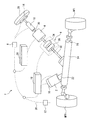
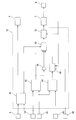
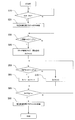
- FIG. 1 is a diagram showing a schematic configuration of a vehicle provided with a steering control device according to a first embodiment of the present invention. It is a block diagram explaining the detailed composition of a steering motor control part. It is a flow chart which shows processing in which a clutch control part generates a clutch control flag and a steering control switching flag. It is a block diagram explaining the detailed composition of a reaction force motor control part. It is a time chart which shows an example of the operation performed using a steering control device. It is a block diagram explaining the detailed composition of the steering motor control part with which the steering control device of a second embodiment of the present invention is provided.
- FIG. 1 is a view showing a schematic configuration of a vehicle provided with a steering control device for a vehicle according to the present embodiment (which may be referred to as “steering control device” in the following description).
- the vehicle provided with the steering control device 1 of the present embodiment is a vehicle to which the SBW system is applied.
- driving of the steering motor is controlled according to the operation of a steering operation element (steering wheel) steered by the driver of the vehicle, and control of steering the steered wheels is performed to progress the vehicle. Change the direction.
- the drive control of the steering motor switches the backup clutch interposed between the steering operator and the steered wheels to an open state, which is a normal state, to provide a torque transmission path between the steering operator and the steered wheels as a machine. In a state of being separated
- the steering control device 1 of the present embodiment includes a steering motor 2, a reaction force motor 4, and a backup clutch 6.
- the steering control device 1 includes an engine command detection unit 8, a steering torque detection unit 10, a vehicle speed detection unit 12, a steering angle detection unit 14, a steering angle detection unit 16, and a steering motor control unit And a reaction force motor control unit 20.
- the steering motor 2 is a motor driven according to a steering motor command current output from the steering motor control unit 18, and outputs a steering torque for steering the steered wheels W.
- the steering torque output from the steering motor 2 is transmitted to the rack gear 24 via the steering motor output shaft 22 rotated by the driving of the steering motor 2.
- the rack gear 24 has a rack shaft 26 that is displaced in the vehicle width direction according to the rotation of the steering motor output shaft 22. Both ends of the rack shaft 26 are connected to the steered wheels W, respectively.
- the steered wheels W are front wheels (left and right front wheels) of the vehicle, and are steered according to the displacement of the rack shaft 26 in the vehicle width direction to change the traveling direction of the vehicle.
- the steered wheels W are formed by the left and right front wheels.
- the steered wheel W formed by the left front wheel is denoted as steered wheel WFL
- the steered wheel W formed by the right front wheel is denoted as steered wheel WFR.
- the reaction force motor 4 is disposed between the steering actuator 28 and the backup clutch 6.
- the reaction force motor 4 is a motor driven according to a reaction force motor command current output from the reaction force motor control unit 20, and can output a steering reaction force to the steering shaft 30. Thereby, the reaction force motor 4 outputs a steering reaction force to the steering operation element 28 via the steering shaft 30.
- the steering reaction force output from the reaction force motor 4 to the steering operator 28 switches the backup clutch 6 to the open state, and mechanically separates the torque transmission path between the steering operator 28 and the steered wheels W. It is a reaction force that can be output to the steering shaft 30 in the state where it is made to.
- the steering reaction force output from the reaction force motor 4 to the steering shaft 30 is a reaction force acting in the direction opposite to the operation direction in which the driver steers the steering operation element 28. Further, the calculation of the steering reaction force is performed according to the tire axial force acting on the steered wheel W and the steering state of the steering operation element 28. Thereby, an appropriate steering reaction force is transmitted to the driver who steers the steering operation element 28.
- the backup clutch 6 is interposed between the steering operator 28 operated by the driver and the steered wheel W, and switches to the open state or the engaged state according to the clutch command current output from the steering motor control unit 18 . The backup clutch 6 is in the open state in the normal state.
- the steering shaft 30 has one end connected to the steering clutch plate 34 inside the backup clutch 6 and the other end connected to the steering operating element 28 and rotates together with the steering operating element 28.
- the pinion shaft 32 has one end connected to the steering clutch plate 36 inside the backup clutch 6, and a gear (not shown) provided on the other end meshes with the rack gear 24.
- the engine command detection unit 8 outputs, to the steering motor control unit 18, an information signal including the state (engine drive or engine stop) of an engine (not shown) which is a drive source for driving the drive wheels.
- the drive wheel is a rear wheel (left and right rear wheels) of a vehicle (not shown), but the invention is not limited thereto.
- the steered wheel W is a front wheel of the vehicle.
- the drive wheel may also be used.
- a drive source is not limited to an engine, It is good also as a motor which can drive a driving wheel.
- the steering torque detection unit 10 is provided, for example, on a steering column (not shown) that rotatably supports the steering operation element 28, and detects a torque applied to the steering shaft 30 by the driver operating the steering operation element 28. . Then, the steering torque detection unit 10 outputs an information signal including the detected steering torque to the steering motor control unit 18.
- the steering torque may be described as "torque sensor value Vts".
- the vehicle speed detection unit 12 is a known vehicle speed sensor, and detects the vehicle speed of the vehicle. Then, an information signal including the detected vehicle speed is output to the steering motor control unit 18 and the reaction force motor control unit 20.
- the steering angle detection unit 14 is formed, for example, using a resolver or the like, and is provided on the steering column in the same manner as the steering torque detection unit 10. Further, the steering angle detection unit 14 detects a current steering angle which is a current rotation angle (steering operation amount) of the steering operation element 28. Then, the steering angle detection unit 14 outputs an information signal including the detected current steering angle of the steering operation element 28 to the steering motor control unit 18 and the reaction force motor control unit 20.
- the current steering angle may be described as “current steering angle ⁇ s”.
- the turning angle detection unit 16 is formed using, for example, a resolver or the like, and is provided to the turning motor 2. Further, the turning angle detection unit 16 detects a rotation angle (turning angle) of the turning motor 2. Then, the turning angle detection unit 16 outputs, to the turning motor control unit 18, an information signal including the detected turning angle (which may be described as "turning motor rotation angle" in the following description). . In the following description, the steering motor rotation angle may be described as “the actual steering angle ⁇ t”.
- the steering motor control unit 18 inputs and outputs information signals through the reaction force motor control unit 20, the engine command detection unit 8, the vehicle speed detection unit 12, and a communication line 38 such as CAN (Controller Area Network). .
- the steering motor control unit 18 drives and controls the steering motor 2 based on the information signal input via the communication line 38 and the information signal input from the steering angle detection unit 14. The detailed configuration of the steering motor control unit 18 will be described later.
- the reaction force motor control unit 20 performs input and output of information signals via the steering motor control unit 18 and the vehicle speed detection unit 12 and the communication line 38. Further, the reaction force motor control unit 20 drives and controls the reaction force motor 4 based on an information signal received via the communication line 38 and an information signal received from the steering angle detection unit 14. The detailed configuration of the reaction force motor control unit 20 will be described later.
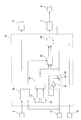
- FIG. 2 is a block diagram for explaining the detailed configuration of the steering motor control unit 18.
- the steering motor control unit 18 includes a clutch control unit 40, an EPS control unit 42, and an SBW steering command angle calculation unit 44.
- the steering motor control unit 18 includes a gain addition unit 46, a steering position servo control unit 48, a steering instruction current switching unit 50, and a steering instruction current servo control unit 52.
- the clutch control unit 40 receives the information signal output from the engine command detection unit 8 and the information signal output from the steering torque detection unit 10. Then, based on the state of the engine included in the information signal output from the engine command detection unit 8 and the torque sensor value Vts included in the information signal output from the steering torque detection unit 10, a clutch control flag and a steering control switching flag are generated. .
- the clutch control unit 40 outputs an information signal including the generated clutch control flag to the backup clutch 6 as a clutch command current.
- the clutch control unit 40 outputs an information signal including the generated turning control switching flag to the turning command current switching unit 50.
- the clutch control flag is a command value for switching the clutch command current to be output to the backup clutch 6, and there are an open command and an engagement command.
- the steering control switching flag is a command value for switching the steering command current to be output to the steering motor 2, and has an EPS state and an SBW state.
- FIG. 3 is a flowchart showing a process in which the clutch control unit 40 generates a clutch control flag and a turning control switching flag.
- the flowchart shown in FIG. 3 starts from the state in which the engine of the vehicle is stopped ("START" shown in the figure).
- step S10 referring to the information signal output from the engine command detection unit 8, it is detected whether the stopped engine is driving or not, and it is determined whether the engine is started (in the figure Show "IGN ON?"
- step S30 the information signal output from the steering torque detection unit 10 is referred to. Then, it is determined whether or not the absolute value of the torque sensor value Vts applied to the steering shaft 30 by the driver is equal to or less than a preset clutch release start torque Ts1 (“
- a preset clutch release start torque Ts1 (“
- the steering torque in the state of being rotated counterclockwise is defined as a negative (-) torque.
- the clutch release start torque Ts1 is set, for example, according to the configuration of the vehicle provided with the steering control device 1 (for example, the rigidity of the steering operation element 28 and the steering shaft 30). Further, the clutch release start torque Ts1 is stored in the clutch control unit 40. The clutch release start torque Ts1 is calculated, for example, by an experiment. The value (torque value) of the clutch release start torque Ts1 is determined by the driver who is steering the steering operation element 28 via the hand holding the steering operation element 28 when the backup clutch 6 is released. The impact received from 28 is a small value.
- step S30 If it is determined in step S30 that the absolute value of the torque sensor value Vts is less than or equal to the clutch release start torque Ts1 ("Y" shown in the drawing), the process performed by the clutch control unit 40 proceeds to step S40. On the other hand, when it is determined in step S30 that the absolute value of the torque sensor value Vts exceeds the clutch release start torque Ts1 ("N" shown in the drawing), the clutch control unit 40 repeats the process of step S30.
- the process performed by the clutch control unit 40 proceeds to step S50.
- step S50 the information signal output from the steering torque detection unit 10 is referred to. Then, it is determined whether or not the absolute value of the torque sensor value Vts applied to the steering shaft 30 by the driver is equal to or less than a preset clutch disengagement estimated torque Ts2 (shown in the figure “
- the clutch release estimated torque Ts2 is a torque less than the clutch release start torque Ts1, and for example, according to the configuration of the vehicle provided with the steering control device 1 (for example, the rigidity of the steering operation element 28 and the steering shaft 30).
- the clutch release estimated torque Ts2 is stored in the clutch control unit 40 in the same manner as the clutch release start torque Ts1.
- the clutch release estimated torque Ts2 is calculated by, for example, an experiment, as with the clutch release start torque Ts1.
- step S50 If it is determined in step S50 that the absolute value of the torque sensor value Vts is equal to or less than the clutch release estimated torque Ts2 ("Y" shown in the drawing), the process performed by the clutch control unit 40 proceeds to step S60. On the other hand, when it is determined in step S50 that the absolute value of the torque sensor value Vts exceeds the clutch release estimated torque Ts2 ("N" shown in the figure), the process performed by the clutch control unit 40 proceeds to step S70. .
- step S60 measurement of a determination elapsed time, which is a time during which the absolute value of the torque sensor value Vts is equal to or less than the estimated clutch release torque Ts2, is started.
- the process performed by the clutch control unit 40 proceeds to step S80.
- step S80 it is determined whether or not the elapsed time for determination measured by the timer is equal to or greater than a preset SBW switching determination time Tm ("the elapsed time for determination TmTm?" Shown in the figure).
- the SBW switching determination time Tm is an elapsed time from when the process of shifting the state of the backup clutch 6 from the engaged state to the released state is started and it is estimated that the backup clutch 6 has completely shifted to the released state. It is. Further, the SBW switching determination time Tm is set, for example, according to the configuration of the vehicle provided with the steering control device 1 (for example, the rigidity of the steering operation element 28 and the steering shaft 30).
- the SBW switching determination time Tm is stored in the clutch control unit 40 in the same manner as the clutch release start torque Ts1.
- the SBW switching determination time Tm is calculated, for example, by experiment, as with the clutch release start torque Ts1. If it is determined in step S80 that the determination elapsed time is equal to or longer than the SBW switching determination time Tm ("Y" shown in the drawing), the process performed by the clutch control unit 40 proceeds to step S90.
- step S80 when it is determined in step S80 that the determination elapsed time is less than the SBW switching determination time Tm ("N" shown in the drawing), the process performed by the clutch control unit 40 proceeds to step S50.
- step S90 when the steering control switching flag is generated in the SBW state, the processing performed by the clutch control unit 40 is ended ("END" shown in the figure).
- the clutch control unit 40 brings the backup clutch 6 into engagement when starting the engine.
- the steering torque detected by the steering torque detection unit 10 after starting the engine becomes equal to or less than the clutch release start torque Ts1
- the backup clutch 6 in the engaged state is switched to the released state.
- the transition from the engaged state of the backup clutch 6 to the open state is determined if the determination elapsed time is equal to or longer than the SBW switching determination time Tm. Is determined to have ended.
- the EPS control unit 42 receives inputs of the information signal output from the steering torque detection unit 10 and the information signal output from the vehicle speed detection unit 12. Then, based on the torque sensor value Vts included in the information signal output from the steering torque detection unit 10 and the vehicle speed included in the information signal output from the vehicle speed detection unit 12, the EPS assist current at failure is calculated. Further, the EPS control unit 42 outputs an information signal including the calculated EPS assist current at failure to the gain adding unit 46 and the steering command current switching unit 50.
- the EPS assist current at the time of failure means, for example, a steering motor command current for outputting a steering assist torque from the steering motor 2 to the steered wheels W when an abnormality occurs in the SBW system such as disconnection or the like.
- a command value according to
- the steering assist torque that the steering motor 2 outputs to the steered wheels W switches the backup clutch 6 to the engaged state, and mechanically connects the torque transmission path between the steering operator 28 and the steered wheels W It is a torque that can be output to the turning wheel W in a state where it is made to.
- the steering assist torque output by the steering motor 2 with the backup clutch 6 in the engaged state at the start of the engine is set to a value that makes the steering torque equal to or less than the clutch release start torque.
- the torque value of the steering assist torque output by the steering motor 2 with the backup clutch 6 engaged when starting the engine is released, and the steering torque is released for the driver operating the steering operation element 28 A value that urges the steering operation to be less than the starting torque.
- the backup clutch 6 is engaged, and the steering assist torque output by the steering motor 2 is output as a torque on the opposite side to the steering direction of the steering operating element 28 by the driver, and the output torque is output. , And transmitted to the steering control 28 via a torque transmission path.
- the torque value of the steering assist torque that urges the driver who is operating the steering operation element 28 to make the steering torque less than the clutch release start torque is, for example, a vehicle provided with the steering control device 1 Based on the performance specifications of
- the SBW turning command angle calculation unit 44 receives an input of the information signal output from the vehicle speed detection unit 12 and the information signal output from the steering angle detection unit 14. Then, based on the vehicle speed included in the information signal output from the vehicle speed detection unit 12 and the current steering angle ⁇ s included in the information signal output from the steering angle detection unit 14, the steering instruction angle is calculated. Further, the SBW turning command angle calculation unit 44 outputs an information signal including the calculated turning command angle to the turning position servo control unit 48.
- the turning command angle calculates a target turning angle according to the operation of the steering operation element 28 by the driver, and a current for driving and controlling the turning motor 2 according to the calculated target turning angle. It is a command value.
- the gain adding unit 46 receives an input of the information signal output from the EPS control unit 42. Then, the EPS assist current at the time of failure included in the information signal output by the EPS control unit 42 is multiplied by a pre-set assist gain at start-up to calculate the EPS assist current at start-up.
- the gain adding unit 46 outputs an information signal including the calculated starting EPS assist current to the turning command current switching unit 50.
- the start-up EPS assist current is a command value according to the steering motor command current for outputting the steering assist torque from the steering motor 2 to the steered wheels W when the engine is started.
- the starting assist gain is set so that the starting EPS assist current becomes a larger value than the missing EPS assist current, and the gain adding unit 46 I will remember it.
- the steering assist torque output from the steering motor 2 with the backup clutch 6 in the engaged state at the start of the engine is output when the steering motor 1 fails and the steering motor 2 outputs the steering clutch 2 in the engaged state.
- the torque is larger than the rudder assist torque.
- the turning position servo control unit 48 receives an input of the information signal output from the SBW turning command angle calculation unit 44. Then, based on the turning command angle included in the information signal output from the SBW turning command angle calculation unit 44, the SBW turning command current is calculated.
- the turning position servo control unit 48 outputs an information signal including the calculated SBW turning command current to the turning command current switching unit 50 and the turning command current servo control unit 52.
- the SBW turning command current is a command value corresponding to the turning motor command current for outputting a torque corresponding to the target turning angle to the turning wheel W.
- the turning position servo control unit 48 receives an input of the information signal output by the turning angle detection unit 16 and an input of the information signal output by the turning command current servo control unit 52. In addition to this, the steering position servo control unit 48 detects a steering motor command current finally output to the steering motor 2.
- the information signals output from the steering angle detection unit 16 and the steering command current servo control unit 52 and the steering motor command current finally output to the steering motor 2 are used to calculate the SBW steering command current.
- the turning position servo control unit 48 performs feedback control regarding the calculation of the SBW turning command current.
- the turning command current switching unit 50 receives an input of an information signal output from the clutch control unit 40, the EPS control unit 42, the gain adding unit 46, and the turning position servo control unit 48. In addition, the turning command current switching unit 50 switches the turning command current based on the turning control switching flag included in the information signal output from the clutch control unit 40. Then, an information signal including the switched current is output to the turning command current servo control unit 52.
- the turning command current is switched to the EPS assist current at failure.
- the abnormality occurring in the SBW system is detected, for example, by a monitoring unit (not shown) that monitors the state of the SBW system.
- the turning control switching flag is in the EPS state and no abnormality occurs in the SBW system, the turning command current is switched to the startup EPS assist current.
- the turning command current is switched to the SBW turning command current.
- the turning command current servo control unit 52 receives an input of the information signal output from the turning command current switching unit 50. Then, the voltage supplied to the steering motor 2 is changed so that the steering motor command current according to the steering command current included in the information signal output by the steering command current switching unit 50 is input to the steering motor 2
- the turning command current servo control unit 52 performs input and output of information signals with the turning position servo control unit 48.
- the information signal output from the steering command current servo control unit 52 to the steering position servo control unit 48 includes the voltage supplied to the steering motor 2.
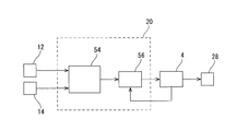
- FIG. 4 is a block diagram for explaining the detailed configuration of the reaction force motor control unit 20.
- the reaction force motor control unit 20 includes an SBW reaction force command current calculation unit 54 and a reaction force command current servo control unit 56.
- the SBW reaction force command current calculation unit 54 receives an input of the information signal output from the vehicle speed detection unit 12 and the information signal output from the steering angle detection unit 14. Then, based on the vehicle speed included in the information signal output from the vehicle speed detection unit 12 and the current steering angle ⁇ s included in the information signal output from the steering angle detection unit 14, the reaction force command current is calculated.
- the SBW reaction force command current calculation unit 54 outputs an information signal including the calculated reaction force command current to the reaction force command current servo control unit 56.
- the reaction force command current is a current command value for driving and controlling the reaction force motor 4.
- the reaction force command current is calculated, for example, by multiplying the actual turning angle ⁇ t by a preset reaction force motor gain.
- the reaction force motor gain is set in advance using a reaction force motor gain map.
- the reaction force motor gain map is a map that depends on the vehicle speed and the steering angle of the steering operation element 28, and is formed in advance and stored in the SBW reaction force command current calculation unit 54.
- the SBW reaction force command current calculation unit 54 outputs an information signal including the calculated reaction force command current to the reaction force command current servo control unit 56.
- the reaction force command current servo control unit 56 receives an input of the information signal output from the SBW reaction force command current calculation unit 54. Then, the voltage supplied to the reaction force motor 4 is set so that the reaction force motor command current according to the reaction force command current included in the information signal output from the SBW reaction force command current calculation unit 54 is input to the reaction force motor 4. Change. Further, the reaction force command current servo control unit 56 detects a reaction force motor command current finally output to the reaction force motor 4. Then, the reaction force motor command current finally output to the reaction force motor 4 is used to control the voltage supplied to the reaction force motor 4. As a result, feedback control regarding the voltage supplied to the reaction force command current servo control unit 56 reaction force motor 4 is performed.
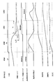
- FIG. 5 is a time chart showing an example of the operation performed using the steering control device 1.
- the time chart shown in FIG. 5 is in a state where the engine is stopped and the driver who gets on the vehicle and sits in the driver's seat is waiting for the operation of the ignition switch (not shown). Start from "State A").
- the ignition switch is formed of, for example, a button (ignition button) operated by the driver of the vehicle.
- the driver steers the steering control 28 will be described, such as when the driver of the vehicle holds the steering control 28 in the state A. Therefore, in the state A, as shown in the [steering torque] column, the torque sensor value Vts detected by the steering torque detection unit 10 is larger than the state where the driver is not steering the steering operation element 28. Further, in the state A, since the clutch control flag is the "engagement command", the backup clutch 6 is engaged, and the torque transmission path between the steering operation element 28 and the steered wheel W is mechanically coupled. .
- the current steering angle ⁇ s detected by the steering angle detection unit 14 changes as shown in the [steering angle] column in accordance with the steering operation of the steering operation element 28 by the driver.
- the actual turning angle ⁇ t detected by the turning angle detection unit 16 changes.
- the operation performed using the steering control device 1 is Transition from state A to state B.
- the EPS control unit 42 calculates the EPS assist current at failure, and outputs an information signal including the calculated EPS assist current at failure to the gain adding unit 46 and the turning command current switching unit 50. Then, the gain adding unit 46 multiplies the failure-time EPS assist current by the start-up assist gain, and calculates a start-up EPS assist current that is larger than the failure-time EPS assist current. Furthermore, the gain adding unit 46 outputs an information signal including the calculated starting EPS assist current to the turning command current switching unit 50.
- the turning command current switching unit 50 switches the turning command current to the startup EPS assist current. Furthermore, an information signal including the EPS assist current at startup is output to the turning command current servo control unit 52. Then, the turning command current servo control unit 52 that has received the input of the information signal including the EPS assist current at start-up allows the steering motor command current according to the EPS assist current at start-up to be input to the steering motor 2 , The voltage supplied to the steering motor 2 is changed.
- the steering motor command current input to the steering motor 2 gradually increases ("fade in” shown in the figure) as time passes, It changes according to the steering angle of the steering operation element 28.
- the start-up EPS assist current is set to a value larger than the failure-time EPS assist current. Therefore, when the engine starts, the steering motor command current input to the steering motor 2 is set to a value larger than the steering motor command current input to the steering motor 2 when an abnormality occurs in the SBW system. It becomes possible.
- the steering angle of the steering operation element 28 increases.
- the steering reaction force output to the steering shaft 30 by the reaction force motor 4 gradually increases ("fade in” shown in the figure) as time passes. After that, it changes according to the steering angle of the steering operation element 28.
- the clutch control flag is maintained at the “engagement command”, and the steering control switching flag is maintained at the “EPS state”.
- state B when the steering torque applied to the steering shaft 30 by the driver decreases and the absolute value of the torque sensor value Vts becomes equal to or less than the clutch release start torque Ts1, the operation performed using the steering control device 1 is the state Transition from B to state C.
- state C the clutch control unit 40 generates a clutch control flag as a "release command”. Then, the clutch control unit 40 outputs the information signal generated as the "release command" to the backup clutch 6 as a clutch command current.
- the backup clutch 6 receiving the input of the clutch command current starts transition from the engaged state to the released state.
- the steering control switching flag is maintained in the “EPS state”. Further, in the state C, as in the state B, the reaction force motor 4 outputs the steering reaction force corresponding to the steering angle of the steering operation element 28 to the steering shaft 30. Therefore, the reaction force motor control unit 20 sets the backup clutch 6 in the engaged state and outputs the steering assist torque from the steering motor 2 to when the backup clutch 6 in the engaged state is switched to the released state. The force is output to the steering shaft 30.
- the steering motor 2 outputs the steering assist torque
- the reaction motor 4 outputs the steering reaction force to the steering shaft 30, and the backup of the engaged state is performed.
- the clutch 6 is switched to the release state.
- the impact transmitted from the backup clutch 6 to the steering operation element 28 is more than the steering reaction force that the reaction force motor 4 outputs to the steering shaft 30 Also becomes smaller.
- state C when the absolute value of the torque sensor value Vts becomes equal to or less than the clutch release estimated torque Ts2, the timer possessed by the clutch control unit 40 is started to start measurement of the determination elapsed time.
- the clutch control unit 40 determines that the transition from the engagement state of the backup clutch 6 to the release state is completed. Then, the operation performed using the steering control device 1 shifts from the state C to the state D.
- the clutch control unit 40 In the state D, the clutch control unit 40 generates the steering control switching flag as the “SBW state”. Then, the clutch control unit 40 outputs an information signal including the turning control switching flag generated as the “SBW state” to the turning command current switching unit 50. Therefore, in the present embodiment, in the state where the determination elapsed time is less than the SBW switching determination time Tm, it is determined that the transition from the engagement state of the backup clutch 6 to the release state is not completed, and the steering control switching flag Keep in EPS state.
- the turning command current switching unit 50 switches the turning command current from the start-up EPS assist current to the SBW turning command current. Furthermore, an information signal including the SBW turning command current is output to the turning command current servo control unit 52. Then, the steering command current servo control unit 52 that has received the input of the information signal including the SBW steering command current causes the steering motor command current according to the SBW steering command current to be input to the steering motor 2 , The voltage supplied to the steering motor 2 is changed.
- the steering motor control unit 18 outputs the steering assist torque by the steering motor 2.
- the steering motor control unit 18 responds to the SBW turning command current to turn the steering torque according to the target turning angle.
- the steering motor 2 outputs.
- the steering motor control unit 18 When the clutch control unit 40 determines that the transition from the engagement state of the backup clutch 6 to the release state has ended, the steering motor control unit 18 outputs a steering torque according to the target steering angle to steer the vehicle. Drive control of the motor 2 is performed. Thereby, as shown in the [steering command current] column, the steering motor command current input to the steering motor 2 gradually increases ("fade in” shown in the figure) as time passes, It changes according to the steering angle of the steering operation element 28.
- the steering torque applied by the driver to the steering shaft 30 is detected.
- the backup clutch 6 when starting the engine, the backup clutch 6 is engaged, and when the steering torque detected after the engine start becomes equal to or less than the clutch release start torque Ts1, the backup clutch 6 in the engaged state is switched to the release state.
- the steering assist torque is output by the steering motor 2
- the steering torque according to the target steering angle is The steering motor 2 outputs.
- the clutch control unit 40 brings the backup clutch 6 into engagement when starting the engine, and releases the backup clutch 6 in engagement when the absolute value of the torque sensor value Vts becomes equal to or less than the clutch release start torque Ts1 after the engine is started. Switch to state.
- the steering motor control unit 18 causes the steering motor 2 to output a steering assist torque according to the startup EPS assist current.
- the steering motor 2 outputs the steering torque according to the target steering angle according to the SBW steering command current.
- the state shifts from the EPS state to the SBW state in a state where it is possible to reduce the impact received by the driver via the hand holding the steering operator 28 It is possible to As a result, it is possible to prevent the steering state of the steering operator 28 from deviating from the driver's intention when the engine is started. In addition, it is possible to prevent the driver who holds the steering operation element 28 from taking his hand by the steering operation element 28, and to smoothly shift from the EPS state to the SBW state.
- the clutch control unit 40 switches the backup clutch 6 in the engaged state to the released state. Therefore, it is possible to suppress free vibration of the steering torque detection unit 10 and the steering shaft 30 caused by the fluctuation of the steering torque generated when the backup clutch 6 in the engaged state is switched to the open state. As a result, it is possible to suppress noise and vibration generated when the backup clutch 6 in the engaged state is switched to the open state, and it is possible to reduce the sense of discomfort the driver feels.
- the steering motor control unit 18 sets the torque value of the steering assist torque output by the steering motor 2 with the backup clutch 6 in the engaged state when starting the engine, and a value that makes the steering torque equal to or less than the clutch release start torque Do. For this reason, when switching the backup clutch 6 in the engaged state to the open state, it is possible to shift from the EPS state to the SBW state in a state where it is possible to reduce the discomfort experienced by the driver holding the steering operator 28 It becomes. As a result, it is possible to reduce a sense of incongruity experienced by a driver who grips the steering operation element 28 at the start of the engine, and to smoothly shift from the EPS state to the SBW state.
- the steering motor control unit 18 sets the steering assist torque output when the engine is started to a torque larger than the steering assist torque output when the steering control device 1 fails. That is, the start-up EPS assist current is set to a value larger than the failure-time EPS assist current. Therefore, when the engine starts, the steering motor command current input to the steering motor 2 is set to a value larger than the steering motor command current input to the steering motor 2 when an abnormality occurs in the SBW system. It becomes possible. As a result, it is possible to shorten the time to reduce the steering torque applied by the driver to the steering shaft 30 at the time of starting the engine, and to shorten the time required to switch the backup clutch 6 in the engaged state to the open state.
- the steering reaction force that the reaction force motor 4 outputs to the steering shaft 30 is the impact transmitted from the backup clutch 6 to the steering operation element 28 via the steering shaft 30 when switching from the engaged state to the released state. It becomes smaller than. As a result, it becomes possible to reduce the uncomfortable feeling such as the reaction force fluctuation felt by the driver gripping the steering operation element 28 when the backup clutch 6 is switched from the engaged state to the released state.
- the clutch control unit 40 determines that the transition from the engagement state of the backup clutch 6 to the release state is completed when the determination elapsed time is the SBW switching determination time Tm or more. In addition to this, when the steering motor control unit 18 determines that the clutch control unit 40 completes the transition from the engagement state of the backup clutch 6 to the release state, the steering motor control unit 18 outputs the steering torque according to the target steering angle.
- the clutch control unit 40 determines that the transition from the engagement state of the backup clutch 6 to the release state is not completed when the determination elapsed time is less than the SBW switching determination time Tm, and the steering control switching flag Is maintained in the "EPS state".
- the steering motor 2 maintains the state of outputting the steering assist torque. As a result, it is possible to improve the reliability of the process of shifting the backup clutch 6 from the engaged state to the released state.
- the backup clutch 6 is released in the state where the driving (rotation) of the steering motor 2 and the reaction motor 4 is stopped. There is a way to do it. Furthermore, there is a method of interlocking the driving (rotation) of the steering motor 2 and the driving (rotation) of the reaction force motor 4.
- the driver who grips the steering operation member 28 feels a sense of incongruity due to the impact when the backup clutch 6 is in the released state, and the steering motor 2 and the reaction force motor 4 that are driven in conjunction. You will receive
- the steering torque applied to the steering shaft 30 by the driver operating the steering operation element 28 is detected.
- the backup clutch 6 when starting the engine, the backup clutch 6 is engaged, and when the steering torque detected after the engine start becomes equal to or less than the clutch release start torque Ts1, the backup clutch 6 in the engaged state is switched to the release state.
- the steering assist torque is output by the steering motor 2
- the steering torque according to the target steering angle is The steering motor 2 outputs.
- the state shifts from the EPS state to the SBW state in a state where it is possible to reduce the impact received by the driver via the hand holding the steering operator 28 It is possible to As a result, it is possible to prevent the steering state of the steering operator 28 from deviating from the driver's intention when the engine is started. In addition, it is possible to prevent the driver who holds the steering operation element 28 from taking his hand by the steering operation element 28, and to smoothly shift from the EPS state to the SBW state.
- the clutch control unit 40 determines that the transition from the engagement state of the backup clutch 6 to the release state is completed when the determination elapsed time is the SBW switching determination time Tm or more. It is not limited to That is, for example, the clutch control unit 40 may perform the processing described below.
- the absolute value of the torque sensor value Vts becomes equal to or less than the estimated clutch release torque Ts2 after switching of the backup clutch 6 from the engaged state to the released state starts, the state of the backup clutch 6 shifts from the engaged state to the released state. It determines that it has ended.
- the backup clutch 6 in the released state is switched to the engaged state.
- FIG. 6 is a block diagram for explaining the detailed configuration of the steering motor control unit 18.
- the steering motor control unit 18 includes a clutch control unit 40, an SBW steering command angle computing unit 44, an EPS equivalent steering command angle computing unit 58, and a steering command angle switching unit 60. And a steering position servo control unit 48.
- the configuration of the clutch control unit 40 is the same as that of the first embodiment described above, and thus the description thereof is omitted.
- the SBW turning command angle calculation unit 44 receives an input of the information signal output from the vehicle speed detection unit 12 and the information signal output from the steering angle detection unit 14. Then, based on the vehicle speed included in the information signal output from the vehicle speed detection unit 12 and the current steering angle ⁇ s included in the information signal output from the steering angle detection unit 14, the steering instruction angle is calculated. Further, the SBW turning command angle calculation unit 44 outputs an information signal including the calculated turning command angle to the EPS equivalent turning command angle calculation unit 58 and the turning command angle switching unit 60.
- the EPS equivalent turning command angle calculation unit 58 includes a turning assist torque calculation gain generation unit 62 and a turning command angle correction unit 64.
- the steering assist torque calculation gain generation unit 62 receives an input of the information signal output from the steering torque detection unit 10. Then, the steering assist torque calculation gain generation unit 62 multiplies the torque sensor value Vts included in the information signal output by the steering torque detection unit 10 by a steering assist torque correction coefficient set in advance, and performs steering assistance. Generate a torque calculation gain.
- the steering assist torque correction coefficient is set according to the performance (output and the like) of the steering motor 2 and stored in the steering assist torque calculation gain generation unit 62. Further, the steering assist torque calculation gain generation unit 62 outputs an information signal including the generated steering assist torque calculation gain to the steering command angle correction unit 64.
- the turning command angle correction unit 64 receives an input of the information signal output by the SBW turning command angle calculation unit 44 and the information signal output by the turning assist torque calculation gain generation unit 62. Then, the steering command angle correction unit 64 generates the steering assist torque calculation gain generated by the steering assist torque calculation gain generation unit 62 at the steering command angle included in the information signal output by the SBW steering command angle calculation unit 44. Is added (+) to calculate the EPS equivalent turning command angle.
- the turning command angle correction unit 64 outputs an information signal including the calculated EPS equivalent turning command angle to the turning command angle switching unit 60.
- the EPS equivalent steering command angle is a current command value for driving and controlling the steering motor 2 in accordance with the steering assist torque.
- the EPS equivalent turning command angle calculation unit 58 generates the EPS equivalent turning command angle based on the torque sensor value Vts included in the information signal output from the steering torque detection unit 10 and the steering assist torque calculation gain set in advance. Calculate
- the steering motor control unit 18 corrects the steering command angle for computing the steering torque according to the target steering angle with the steering assist torque computing gain set in advance, Calculate the rudder assist torque.
- the turning command angle switching unit 60 receives the input of the information signal output from the clutch control unit 40, the SBW turning command angle calculation unit 44, and the EPS equivalent turning command angle calculation unit 58.
- the turning command angle switching unit 60 switches the turning command angle based on the turning control switching flag included in the information signal output by the clutch control unit 40. Then, an information signal including the switched steering command angle is output to the steering position servo control unit 48. Specifically, when the turning control switching flag is in the EPS state, the turning command angle is switched to the SBW turning command angle.
- the turning command angle is switched to the EPS equivalent turning command angle.
- the turning position servo control unit 48 receives an input of the information signal output from the turning command angle switching unit 60. Then, based on the turning command angle included in the information signal output from the turning command angle switching unit 60, the turning command current is calculated.
- the steering command current calculated by the steering position servo control unit 48 is a steering motor command for outputting a torque corresponding to the steering command angle switched by the steering command angle switching unit 60 to the steered wheel W. It is a command value according to the current.
- the turning position servo control unit 48 receives an input of the information signal output from the turning angle detection unit 16. In addition to this, the steering position servo control unit 48 detects a steering motor command current finally output to the steering motor 2. Then, the information signal output from the turning angle detection unit 16 and the steering motor command current finally output to the steering motor 2 are used to calculate the steering command current. Thereby, the turning position servo control unit 48 performs feedback control on the calculation of the turning command current. Further, the steering position servo control unit 48 changes the voltage supplied to the steering motor 2 so that the steering motor command current according to the calculated steering command current is input to the steering motor 2.
- the EPS equivalent turning command angle calculation unit 58 calculates the EPS equivalent turning command angle. Then, an information signal including the calculated EPS-equivalent turning command angle is output to the turning command angle switching unit 60. Further, the clutch control unit 40 generates a clutch control flag as a "engagement command” and generates a steering control switching flag as an "EPS state".
- the turning command angle switching unit 60 switches the turning command angle to the EPS equivalent turning command angle. Further, an information signal including the EPS equivalent turning command angle is output to the turning position servo control unit 48.
- the steered position servo control unit 48 receives the information signal including the EPS assist current at the time of start-up so that the steered motor command current according to the EPS equivalent steered command angle is input to the steered motor 2 The voltage supplied to the rudder motor 2 is changed.
- the clutch control unit 40 When the steering torque applied to the steering shaft 30 by the driver decreases and the absolute value of the torque sensor value Vts becomes equal to or less than the clutch release start torque Ts1, the clutch control unit 40 generates a clutch control flag as a release command. Do. Then, the clutch control unit 40 outputs the information signal generated as the "release command" to the backup clutch 6 as a clutch command current. The backup clutch 6 receiving the input of the clutch command current starts transition from the engaged state to the released state. In this state, the steering control switching flag is maintained in the "EPS state". Further, the reaction force motor 4 outputs a steering reaction force corresponding to the steering angle of the steering operation element 28 to the steering shaft 30.
- the clutch control unit 40 determines that the transition from the engagement state of the backup clutch 6 to the release state is completed, and the steering control switching flag is "SBW state Generate as Then, the clutch control unit 40 outputs an information signal including the turning control switching flag generated as the “SBW state” to the turning command angle switching unit 60.
- the turning command angle switching unit 60 switches the turning command angle from the EPS equivalent turning command angle to the SBW turning command angle. Furthermore, an information signal including the SBW turning command angle is output to the turning position servo control unit 48. Then, the steering position servo control unit 48 receives the information signal including the SBW steering command angle so that the steering motor command current according to the SBW steering command angle is input to the steering motor 2 The voltage supplied to the steering motor 2 is changed.
- the steering motor control unit 18 corrects the steering command angle for calculating the steering torque according to the target steering angle by the steering assist torque calculation gain set in advance. , To calculate the steering assist torque.
- the turning control switching flag is switched from the "EPS state” to the "SBW state
- the turning position servo control unit 48 responds to the turning command angle not corrected by the turning assist torque calculation gain, The voltage supplied to the steering motor 2 is changed. Therefore, in the present embodiment, when the steering control switching flag is switched from the "EPS state” to the "SBW state", it is possible to continue servo control of the steering angle by the steering position servo control unit 48 Become.
Landscapes
- Engineering & Computer Science (AREA)
- Chemical & Material Sciences (AREA)
- Combustion & Propulsion (AREA)
- Transportation (AREA)
- Mechanical Engineering (AREA)
- Physics & Mathematics (AREA)
- Mathematical Physics (AREA)
- Steering Control In Accordance With Driving Conditions (AREA)
- Power Steering Mechanism (AREA)
Abstract
Description
上述したバックアップクラッチの状態を診断するためには、バックアップクラッチの締結及び開放を頻繁に行う必要があるが、バックアップクラッチの締結及び開放時には作動音が発生する。このため、例えば、特許文献1に記載されているように、車両の運転者が車内に存在しないことを検出すると、バックアップクラッチの診断を開始する技術が提案されている。
本発明は、上記のような問題点に着目してなされたもので、エンジンの始動時において、操舵操作子の操舵状態が運転者の意図と乖離することを抑制することが可能な、車両の操舵制御装置及び操舵制御方法を提供することを目的とする。
これに加え、バックアップクラッチの状態を締結状態とすると、操舵操作子の操作に応じて転舵輪の転舵を補助する転舵補助トルクを転舵モータで出力する。さらに、締結状態のバックアップクラッチを開放状態に切り換えると、操舵操作子の操作に応じた目標転舵角に応じた転舵トルクを転舵モータで出力する。
このため、バックアップクラッチを開放状態に切り換える際に、運転者が操舵操作子を把持している手を介して受ける衝撃を低減させることが可能となる。これにより、駆動源の始動時に操舵操作子の操舵状態が運転者の意図と乖離することを抑制することが可能となる。
(第一実施形態)
以下、本発明の第一実施形態(以下、本実施形態と記載する)について、図面を参照しつつ説明する。
(構成)
図1は、本実施形態の車両の操舵制御装置(以降の説明では、「操舵制御装置」と記載する場合がある)を備えた車両の概略構成を示す図である。
本実施形態の操舵制御装置1を備えた車両は、SBWシステムを適用した車両である。
ここで、SBWシステムでは、車両の運転者が操舵操作する操舵操作子(ステアリングホイール)の操作に応じて転舵モータを駆動制御し、転舵輪を転舵する制御を行うことにより、車両の進行方向を変化させる。転舵モータの駆動制御は、操舵操作子と転舵輪との間に介装するバックアップクラッチを、通常状態である開放状態に切り換えて、操舵操作子と転舵輪との間のトルク伝達経路を機械的に分離した状態で行う。
図1中に示すように、本実施形態の操舵制御装置1は、転舵モータ2と、反力モータ4と、バックアップクラッチ6を備える。これに加え、操舵制御装置1は、エンジン指令検出部8と、操舵トルク検出部10と、車速検出部12と、操舵角検出部14と、転舵角検出部16と、転舵モータ制御部18と、反力モータ制御部20を備える。
ラックギア24は、転舵モータ出力軸22の回転に応じて車幅方向へ変位するラック軸26を有する。ラック軸26の両端は、それぞれ、転舵輪Wに連結する。
反力モータ4は、操舵操作子28とバックアップクラッチ6との間に配置する。
ここで、反力モータ4が操舵操作子28へ出力する操舵反力は、バックアップクラッチ6を開放状態に切り換えて、操舵操作子28と転舵輪Wとの間のトルク伝達経路を機械的に分離させている状態で、ステアリングシャフト30へ出力可能な反力である。
また、操舵反力の演算は、転舵輪Wに作用しているタイヤ軸力や操舵操作子28の操舵状態に応じて行なう。これにより、操舵操作子28を操舵する運転者へ、適切な操舵反力を伝達する。
バックアップクラッチ6は、運転者が操作する操舵操作子28と転舵輪Wとの間に介装し、転舵モータ制御部18が出力するクラッチ指令電流に応じて、開放状態または締結状態に切り換わる。なお、バックアップクラッチ6は、通常状態では開放状態である。
したがって、ステアリングシャフト30は、トルク伝達経路の一部を形成する。
エンジン指令検出部8は、駆動輪を駆動する駆動源であるエンジン(図示せず)の状態(エンジン駆動、または、エンジン停止)を含む情報信号を、転舵モータ制御部18へ出力する。なお、本実施形態では、一例として、駆動輪を、図示しない車両の後輪(左右後輪)とするが、これに限定するものではなく、駆動輪を、車両の前輪として、転舵輪Wが駆動輪を兼ねる構成としてもよい。また、駆動源は、エンジンに限定するものではなく、駆動輪を駆動可能なモータとしてもよい。
操舵角検出部14は、例えば、レゾルバ等を用いて形成し、操舵トルク検出部10と同様、ステアリングコラムに設ける。
また、操舵角検出部14は、操舵操作子28の現在の回転角度(操舵操作量)である現在操舵角を検出する。そして、操舵角検出部14は、検出した操舵操作子28の現在操舵角を含む情報信号を、転舵モータ制御部18及び反力モータ制御部20へ出力する。なお、以降の説明では、現在操舵角を、「現在操舵角θs」と記載する場合がある。
また、転舵角検出部16は、転舵モータ2の回転角度(転舵角度)を検出する。そして、転舵角検出部16は、検出した転舵角度(以降の説明では、「転舵モータ回転角」と記載する場合がある)を含む情報信号を、転舵モータ制御部18へ出力する。なお、以降の説明では、転舵モータ回転角を、「実転舵角θt」と記載する場合がある。
また、転舵モータ制御部18は、通信ライン38を介して入力を受けた情報信号や、操舵角検出部14から入力を受けた情報信号に基づき、転舵モータ2を駆動制御する。なお、転舵モータ制御部18の詳細な構成については、後述する。
また、反力モータ制御部20は、通信ライン38を介して入力を受けた情報信号や、操舵角検出部14から入力を受けた情報信号に基づき、反力モータ4を駆動制御する。なお、反力モータ制御部20の詳細な構成については、後述する。
以下、図1を参照しつつ、図2及び図3を用いて、転舵モータ制御部18の詳細な構成を、図2中に示す他の構成との関連を含めて説明する。
図2は、転舵モータ制御部18の詳細な構成を説明するブロック図である。
図2中に示すように、転舵モータ制御部18は、クラッチ制御部40と、EPS制御部42と、SBW転舵指令角演算部44を備える。これに加え、転舵モータ制御部18は、ゲイン付加部46と、転舵位置サーボ制御部48と、転舵指令電流切替部50と、転舵指令電流サーボ制御部52を備える。
ここで、クラッチ制御フラグは、バックアップクラッチ6へ出力するクラッチ指令電流を切り替えるための指令値であり、開放指令と締結指令がある。
また、転舵制御切替フラグは、転舵モータ2へ出力する転舵指令電流を切り替えるための指令値であり、EPS状態とSBW状態がある。
図3は、クラッチ制御部40が、クラッチ制御フラグ及び転舵制御切替フラグを生成する処理を示すフローチャートである。
図3中に示すフローチャートは、車両のエンジンが停止している状態から開始(図中に示す「START」)する。
まず、ステップS10において、エンジン指令検出部8が出力した情報信号を参照して、停止しているエンジンが駆動しているか否かを検出し、エンジンが始動しているか否かを判定(図中に示す「IGN ON?」)する。
一方、ステップS10において、エンジンが始動していない(図中に示す「N」)と判定すると、クラッチ制御部40は、ステップS10の処理を繰り返す。
ステップS20では、転舵制御切替フラグを、EPS状態として生成(図中に示す「転舵制御切替フラグ=EPS状態」)する。ステップS20において、転舵制御切替フラグをEPS状態として生成すると、クラッチ制御部40が行なう処理は、ステップS30へ移行する。
クラッチ開放開始トルクTs1の値(トルク値)は、操舵操作子28を操舵している運転者が、バックアップクラッチ6の開放時に、操舵操作子28を把持している手を介して、操舵操作子28から受ける衝撃が小さい値である。
一方、ステップS30において、トルクセンサ値Vtsの絶対値がクラッチ開放開始トルクTs1を超えている(図中に示す「N」)と判定すると、クラッチ制御部40は、ステップS30の処理を繰り返す。
ステップS50では、操舵トルク検出部10が出力した情報信号を参照する。そして、運転者がステアリングシャフト30に加えているトルクセンサ値Vtsの絶対値が、予め設定したクラッチ開放推定トルクTs2以下であるか否かを判定(図中に示す「|操舵トルク|≦Ts2?」)する。
一方、ステップS50において、トルクセンサ値Vtsの絶対値がクラッチ開放推定トルクTs2を超えている(図中に示す「N」)と判定すると、クラッチ制御部40が行なう処理は、ステップS70へ移行する。
ステップS80では、タイマで計測している判定用経過時間が、予め設定したSBW切替判定時間Tm以上であるか否かを判定(図中に示す「判定用経過時間≧Tm?」)する。
ステップS80において、判定用経過時間がSBW切替判定時間Tm以上である(図中に示す「Y」)と判定すると、クラッチ制御部40が行なう処理は、ステップS90へ移行する。
ステップS90では、転舵制御切替フラグを、SBW状態として生成(図中に示す「転舵制御切替フラグ=SBW状態」)する。ステップS90において、転舵制御切替フラグをSBW状態として生成すると、クラッチ制御部40が行なう処理は終了(図中に示す「END」)する。
また、クラッチ制御部40は、バックアップクラッチ6の締結状態から開放状態への切り換え開始後に、判定用経過時間がSBW切替判定時間Tm以上であると、バックアップクラッチ6の締結状態から開放状態への移行が終了したと判定する。
また、EPS制御部42は、演算した失陥時EPSアシスト電流を含む情報信号を、ゲイン付加部46及び転舵指令電流切替部50へ出力する。
ここで、転舵モータ2が転舵輪Wへ出力する転舵補助トルクは、バックアップクラッチ6を締結状態に切り換えて、操舵操作子28と転舵輪Wとの間のトルク伝達経路を機械的に連結させている状態で、転舵輪Wへ出力可能なトルクである。
これにより、エンジンの始動時にバックアップクラッチ6を締結状態として転舵モータ2が出力する転舵補助トルクのトルク値を、操舵操作子28を操作している運転者に対して、操舵トルクをクラッチ開放開始トルク以下とする操舵操作を促す値とする。
なお、操舵操作子28を操作している運転者に対して、操舵トルクをクラッチ開放開始トルク以下とする操舵操作を促す転舵補助トルクのトルク値は、例えば、操舵制御装置1を備えた車両の性能諸元等に基づき、実験により算出する。
また、SBW転舵指令角演算部44は、演算した転舵指令角を含む情報信号を、転舵位置サーボ制御部48へ出力する。
ゲイン付加部46は、EPS制御部42が出力した情報信号の入力を受ける。そして、EPS制御部42が出力した情報信号が含む失陥時EPSアシスト電流に対し、予め設定した始動時アシスト用ゲインを乗算して、始動時EPSアシスト電流を演算する。
ここで、始動時EPSアシスト電流とは、エンジンの始動時に、転舵モータ2から転舵輪Wへ転舵補助トルクを出力するための転舵モータ指令電流に応じた指令値である。
また、始動時アシスト用ゲインは、転舵モータ2の性能(出力等)に応じて、始動時EPSアシスト電流が失陥時EPSアシスト電流よりも大きい値となるように設定し、ゲイン付加部46に記憶させておく。
転舵位置サーボ制御部48は、SBW転舵指令角演算部44が出力した情報信号の入力を受ける。そして、SBW転舵指令角演算部44が出力した情報信号が含む転舵指令角に基づき、SBW転舵指令電流を演算する。
ここで、SBW転舵指令電流とは、目標転舵角に応じたトルクを転舵輪Wへ出力するための転舵モータ指令電流に応じた指令値である。
また、転舵位置サーボ制御部48は、転舵角検出部16が出力した情報信号の入力と、転舵指令電流サーボ制御部52が出力した情報信号の入力を受ける。これに加え、転舵位置サーボ制御部48は、転舵モータ2へ最終的に出力された転舵モータ指令電流を検出する。そして、転舵角検出部16及び転舵指令電流サーボ制御部52が出力した情報信号と、転舵モータ2へ最終的に出力された転舵モータ指令電流を、SBW転舵指令電流の演算に用いる。これにより、転舵位置サーボ制御部48は、SBW転舵指令電流の演算に関するフィードバック制御を行なう。
また、転舵指令電流切替部50は、クラッチ制御部40が出力した情報信号が含む転舵制御切替フラグに基づき、転舵指令電流を切り替える。そして、切り替えた電流を含む情報信号を、転舵指令電流サーボ制御部52へ出力する。
また、転舵制御切替フラグがEPS状態であり、SBWシステムに異常が発生していない場合に、転舵指令電流を、始動時EPSアシスト電流に切り替える。
転舵指令電流サーボ制御部52は、転舵指令電流切替部50が出力した情報信号の入力を受ける。そして、転舵指令電流切替部50が出力した情報信号が含む転舵指令電流に応じた転舵モータ指令電流が転舵モータ2へ入力されるように、転舵モータ2に供給する電圧を変化させる。
また、転舵指令電流サーボ制御部52は、転舵位置サーボ制御部48との間で情報信号の入出力を行なう。転舵指令電流サーボ制御部52から転舵位置サーボ制御部48へ出力する情報信号には、転舵モータ2に供給する電圧を含む。
以下、図1から図3を参照しつつ、図4を用いて、反力モータ制御部20の構成を、図4中に示す他の構成との関連を含めて説明する。
図4は、反力モータ制御部20の詳細な構成を説明するブロック図である。
図4中に示すように、反力モータ制御部20は、SBW反力指令電流演算部54と、反力指令電流サーボ制御部56を備える。
SBW反力指令電流演算部54は、車速検出部12が出力した情報信号と、操舵角検出部14が出力した情報信号の入力を受ける。そして、車速検出部12が出力した情報信号が含む車速と、操舵角検出部14が出力した情報信号が含む現在操舵角θsに基づき、反力指令電流を演算する。
ここで、反力指令電流は、反力モータ4を駆動制御するための電流指令値である。
また、反力指令電流は、例えば、実転舵角θtに、予め設定した反力モータ用ゲインを乗算して演算する。ここで、反力モータ用ゲインは、反力モータゲイン用マップを用いて、予め設定する。なお、反力モータゲイン用マップは、車速及び操舵操作子28の操舵角に依存するマップであり、予め形成して、SBW反力指令電流演算部54に格納する。
反力指令電流サーボ制御部56は、SBW反力指令電流演算部54が出力した情報信号の入力を受ける。そして、SBW反力指令電流演算部54が出力した情報信号が含む反力指令電流に応じた反力モータ指令電流が反力モータ4へ入力されるように、反力モータ4に供給する電圧を変化させる。
また、反力指令電流サーボ制御部56は、反力モータ4へ最終的に出力された反力モータ指令電流を検出する。そして、反力モータ4へ最終的に出力された反力モータ指令電流を、反力モータ4に供給する電圧の制御に用いる。これにより、反力指令電流サーボ制御部56反力モータ4に供給する電圧に関するフィードバック制御を行なう。
次に、図1から図4を参照しつつ、図5を用いて、本実施形態の操舵制御装置1を用いて行なう動作の一例を説明する。
図5は、操舵制御装置1を用いて行なう動作の一例を示すタイムチャートである。
図5中に示すタイムチャートは、エンジンが停止しており、車両に乗車して運転席に座った運転者による、図示しないイグニッション(ignition)スイッチの操作を待機している状態(図中に示す「状態A」)から開始する。ここで、イグニッションスイッチは、例えば、車両の運転者が操作するボタン(イグニッションボタン)で形成する。
したがって、状態Aでは、[転舵指令電流]欄に示すように、転舵指令電流が「0」であり、また、[反力]欄に示すように、反力モータ4がステアリングシャフト30へ出力する操舵反力は「0」である。
また、[クラッチ制御フラグ]欄に示すように、クラッチ制御フラグは、「締結指令」である。さらに、[転舵制御切替フラグ]欄に示すように、転舵制御切替フラグは、「EPS状態」である。
また、状態Aでは、クラッチ制御フラグが「締結指令」であるため、バックアップクラッチ6が締結されており、操舵操作子28と転舵輪Wとの間のトルク伝達経路が機械的に結合している。
状態Aにおいて、運転者によりイグニッションスイッチが操作され(図中に示す「ON」)、エンジン指令検出部8が、エンジンの状態としてエンジン駆動を検出すると、操舵制御装置1を用いて行なう動作は、状態Aから状態Bへ移行する。
そして、始動時EPSアシスト電流を含む情報信号の入力を受けた転舵指令電流サーボ制御部52は、始動時EPSアシスト電流に応じた転舵モータ指令電流が転舵モータ2へ入力されるように、転舵モータ2に供給する電圧を変化させる。
ここで、本実施形態では、始動時EPSアシスト電流を、失陥時EPSアシスト電流よりも大きい値となるように設定している。このため、エンジンの始動時に転舵モータ2へ入力される転舵モータ指令電流を、SBWシステムに異常が発生した場合に転舵モータ2へ入力される転舵モータ指令電流よりも大きい値とすることが可能となる。
また、状態Bでは、状態Aと同様、クラッチ制御フラグを「締結指令」に維持するとともに、転舵制御切替フラグを「EPS状態」に維持する。
状態Cでは、クラッチ制御部40が、クラッチ制御フラグを「開放指令」として生成する。そして、クラッチ制御部40は、「開放指令」として生成した情報信号を、クラッチ指令電流としてバックアップクラッチ6へ出力する。クラッチ指令電流の入力を受けたバックアップクラッチ6は、締結状態から開放状態への移行を開始する。
また、状態Cでは、状態Bと同様、操舵操作子28の操舵角に応じた操舵反力を、反力モータ4がステアリングシャフト30へ出力する。
したがって、反力モータ制御部20は、バックアップクラッチ6を締結状態として転舵モータ2が転舵補助トルクを出力する状態から、締結状態のバックアップクラッチ6を開放状態に切り換えるまでの間に、操舵反力をステアリングシャフト30へ出力する。
これにより、本実施形態では、締結状態から開放状態に切り換えた際にバックアップクラッチ6から操舵操作子28に伝達される衝撃が、反力モータ4がステアリングシャフト30へ出力している操舵反力よりも小さくなる。
測定した判定用経過時間がSBW切替判定時間Tm以上となると、クラッチ制御部40が、バックアップクラッチ6の締結状態から開放状態への移行が終了したと判定する。そして、操舵制御装置1を用いて行なう動作は、状態Cから状態Dへ移行する。
したがって、本実施形態では、判定用経過時間がSBW切替判定時間Tm未満の状態では、バックアップクラッチ6の締結状態から開放状態への移行が終了していないと判定し、転舵制御切替フラグを「EPS状態」に維持する。
そして、SBW転舵指令電流を含む情報信号の入力を受けた転舵指令電流サーボ制御部52は、SBW転舵指令電流に応じた転舵モータ指令電流が転舵モータ2へ入力されるように、転舵モータ2に供給する電圧を変化させる。
これにより、[転舵指令電流]欄に示すように、転舵モータ2へ入力される転舵モータ指令電流は、時間の経過につれて徐々に増加(図中に示す「フェードイン」)した後、操舵操作子28の操舵角に応じて変化する。
また、状態Dでは、状態Cと同様、クラッチ制御フラグを「開放指令」に維持する。
本実施形態では、以下に記載する効果を奏することが可能となる。
(1)クラッチ制御部40が、エンジンの始動時にバックアップクラッチ6を締結状態とし、エンジンの始動後にトルクセンサ値Vtsの絶対値がクラッチ開放開始トルクTs1以下となると、締結状態のバックアップクラッチ6を開放状態に切り換える。
これに加え、転舵モータ制御部18が、クラッチ制御部40がバックアップクラッチ6の状態を締結状態とすると、始動時EPSアシスト電流に応じた転舵補助トルクを転舵モータ2で出力する。また、クラッチ制御部40が締結状態のバックアップクラッチ6を開放状態に切り換えると、SBW転舵指令電流に応じて、目標転舵角に応じた転舵トルクを転舵モータ2で出力する。
その結果、エンジンの始動時に操舵操作子28の操舵状態が運転者の意図と乖離することを抑制することが可能となる。また、操舵操作子28を把持する運転者が操舵操作子28に手を取られることを抑制するとともに、EPS状態からSBW状態へ円滑に移行させることが可能となる。
このため、締結状態のバックアップクラッチ6を開放状態に切り換えた際に発生する操舵トルクの変動に起因する、操舵トルク検出部10やステアリングシャフト30の自由振動を抑制することが可能となる。
その結果、締結状態のバックアップクラッチ6を開放状態に切り換えた際に発生する騒音や振動を抑制することが可能となるとともに、運転者が感じる違和感を低減させることが可能となる。
このため、締結状態のバックアップクラッチ6を開放状態に切り換える際に、操舵操作子28を把持している運転者の受ける違和感を低減可能とした状態で、EPS状態からSBW状態へ移行することが可能となる。
その結果、エンジンの始動時に操舵操作子28を把持する運転者が受ける違和感低減するとともに、EPS状態からSBW状態へ円滑に移行させることが可能となる。
このため、エンジンの始動時に転舵モータ2へ入力される転舵モータ指令電流を、SBWシステムに異常が発生した場合に転舵モータ2へ入力される転舵モータ指令電流よりも大きい値とすることが可能となる。
その結果、エンジンの始動時に運転者がステアリングシャフト30に加える操舵トルクを減少させる時間を短縮させて、締結状態のバックアップクラッチ6を開放状態に切り換えるまでに要する時間を短縮することが可能となる。
このため、転舵モータ2が転舵補助トルクを出力するとともに、反力モータ4が操舵反力をステアリングシャフト30へ出力している状態で、締結状態のバックアップクラッチ6を開放状態に切り換えることとなる。
その結果、バックアップクラッチ6に開放指令を出力した後であっても、バックアップクラッチ6が締結状態である場合には、転舵モータ2で転舵補助トルクを出力する状態を維持する。これにより、バックアップクラッチ6を締結状態から開放状態へ移行させる処理の確実性を向上させることが可能となる。
しかしながら、上述した二つの方法では、操舵操作子28を把持する運転者が、バックアップクラッチ6を開放状態とする際の衝撃や、連動して駆動する転舵モータ2及び反力モータ4により、違和感を受けることとなる。
その結果、エンジンの始動時に操舵操作子28の操舵状態が運転者の意図と乖離することを抑制することが可能となる。また、操舵操作子28を把持する運転者が操舵操作子28に手を取られることを抑制するとともに、EPS状態からSBW状態へ円滑に移行させることが可能となる。
(1)本実施形態では、クラッチ制御部40が、判定用経過時間がSBW切替判定時間Tm以上であると、バックアップクラッチ6の締結状態から開放状態への移行が終了したと判定したが、これに限定するものではない。
すなわち、例えば、クラッチ制御部40が、以下に記載する処理を行ってもよい。
バックアップクラッチ6の締結状態から開放状態への切り換え開始後に、トルクセンサ値Vtsの絶対値がクラッチ開放推定トルクTs2以下となった時点で、バックアップクラッチ6の状態が締結状態から開放状態への移行が終了したと判定する。また、判定用経過時間がSBW切替判定時間Tm以上となるまでは、トルクセンサ値Vtsの絶対値がクラッチ開放推定トルクTs2を超えると、開放状態のバックアップクラッチ6を締結状態に切り換える。
上記の構成であれば、EPS状態からSBW状態へ移行するまでに経過する時間を短縮することが可能となり、操舵制御装置1の応答性を向上させて、運転者が受ける操舵感を向上させることが可能となる。
以下、本発明の第二実施形態(以下、本実施形態と記載する)について、図1から図5を参照しつつ、図6を用いて説明する。なお、本実施形態は、転舵モータ制御部18の構成を除き、上述した第一実施形態と同様の構成であるため、転舵モータ制御部18以外の説明は省略する。また、上述した第一実施形態と同様の構成については、同一の符合を付して説明する。
図6は、転舵モータ制御部18の詳細な構成を説明するブロック図である。
図6中に示すように、転舵モータ制御部18は、クラッチ制御部40と、SBW転舵指令角演算部44と、EPS相当転舵指令角演算部58と、転舵指令角切替部60と、転舵位置サーボ制御部48を備える。
クラッチ制御部40の構成は、上述した第一実施形態と同様であるため、その説明を省略する。
また、SBW転舵指令角演算部44は、演算した転舵指令角を含む情報信号を、EPS相当転舵指令角演算部58及び転舵指令角切替部60へ出力する。
転舵補助トルク演算ゲイン生成部62は、操舵トルク検出部10が出力した情報信号の入力を受ける。そして、転舵補助トルク演算ゲイン生成部62は、操舵トルク検出部10が出力した情報信号が含むトルクセンサ値Vtsに対して、予め設定した転舵補助トルク補正係数を乗算して、転舵補助トルク演算ゲインを生成する。
また、転舵補助トルク演算ゲイン生成部62は、生成した転舵補助トルク演算ゲインを含む情報信号を、転舵指令角補正部64へ出力する。
転舵指令角補正部64は、SBW転舵指令角演算部44が出力した情報信号と、転舵補助トルク演算ゲイン生成部62が出力した情報信号の入力を受ける。そして、転舵指令角補正部64は、SBW転舵指令角演算部44が出力した情報信号が含む転舵指令角に、転舵補助トルク演算ゲイン生成部62で生成した転舵補助トルク演算ゲインを加算(+)して、EPS相当転舵指令角を演算する。
ここで、EPS相当転舵指令角は、転舵補助トルクに応じて転舵モータ2を駆動制御するための電流指令値である。
以上により、EPS相当転舵指令角演算部58は、操舵トルク検出部10が出力した情報信号が含むトルクセンサ値Vtsと、予め設定した転舵補助トルク演算ゲインに基づき、EPS相当転舵指令角を演算する。
転舵指令角切替部60は、クラッチ制御部40と、SBW転舵指令角演算部44と、EPS相当転舵指令角演算部58が出力した情報信号の入力を受ける。
具体的には、転舵制御切替フラグがEPS状態である場合に、転舵指令角を、SBW転舵指令角に切り替える。
転舵位置サーボ制御部48は、転舵指令角切替部60が出力した情報信号の入力を受ける。そして、転舵指令角切替部60が出力した情報信号が含む転舵指令角に基づき、転舵指令電流を演算する。
ここで、転舵位置サーボ制御部48が演算する転舵指令電流は、転舵指令角切替部60が切り換えた転舵指令角に応じたトルクを転舵輪Wへ出力するための転舵モータ指令電流に応じた指令値である。
また、転舵位置サーボ制御部48は、演算した転舵指令電流に応じた転舵モータ指令電流が転舵モータ2へ入力されるように、転舵モータ2に供給する電圧を変化させる。
次に、図1、図4から図6を参照して、本実施形態の操舵制御装置1を用いて行なう動作の一例を説明する。
本実施形態の操舵制御装置1を備える車両では、運転者がイグニッションスイッチを操作して動作を開始すると、EPS相当転舵指令角演算部58がEPS相当転舵指令角を演算する。そして、この演算したEPS相当転舵指令角を含む情報信号を、転舵指令角切替部60へ出力する。
また、クラッチ制御部40が、クラッチ制御フラグを「締結指令」として生成するとともに、転舵制御切替フラグを「EPS状態」として生成する。
始動時EPSアシスト電流を含む情報信号の入力を受けた転舵位置サーボ制御部48は、EPS相当転舵指令角に応じた転舵モータ指令電流が転舵モータ2へ入力されるように、転舵モータ2に供給する電圧を変化させる。
なお、この状態では、転舵制御切替フラグを「EPS状態」に維持する。また、操舵操作子28の操舵角に応じた操舵反力を、反力モータ4がステアリングシャフト30へ出力する。
測定した判定用経過時間がSBW切替判定時間Tm以上となると、クラッチ制御部40が、バックアップクラッチ6の締結状態から開放状態への移行が終了したと判定し、転舵制御切替フラグを「SBW状態」として生成する。そして、クラッチ制御部40は、「SBW状態」として生成した転舵制御切替フラグを含む情報信号を、転舵指令角切替部60へ出力する。
そして、SBW転舵指令角を含む情報信号の入力を受けた転舵位置サーボ制御部48は、SBW転舵指令角に応じた転舵モータ指令電流が転舵モータ2へ入力されるように、転舵モータ2に供給する電圧を変化させる。
このため、本実施形態では、転舵制御切替フラグを「EPS状態」から「SBW状態」に切り替えた際に、転舵位置サーボ制御部48による転舵角のサーボ制御を継続させることが可能となる。
本実施形態の車両制御装置1であれば、以下に記載する効果を奏することが可能となる。
(1)転舵モータ制御部18が、目標転舵角に応じた転舵トルクを演算するための転舵指令角を、予め設定した転舵補助トルク演算ゲインにより補正して、転舵補助トルクを演算する。
このため、転舵制御切替フラグを「EPS状態」から「SBW状態」に切り替えると、転舵位置サーボ制御部48が、転舵補助トルク演算ゲインで補正していない転舵指令角に応じて、転舵モータ2に供給する電圧を変化させることとなる。
ここでは、限られた数の実施形態を参照しながら説明したが、権利範囲はそれらに限定されるものではなく、上記の開示に基づく各実施形態の改変は当業者にとって自明なことである。
2 転舵モータ
4 反力モータ
6 バックアップクラッチ
8 エンジン指令検出部
10 操舵トルク検出部
12 車速検出部
14 操舵角検出部
16 転舵角検出部
18 転舵モータ制御部
20 反力モータ制御部
22 転舵モータ出力軸
24 ラックギア
26 ラック軸
28 操舵操作子
30 ステアリングシャフト
32 ピニオン軸
34 操舵側クラッチ板
36 転舵側クラッチ板
38 通信ライン
40 クラッチ制御部
42 EPS制御部
44 SBW転舵指令角演算部
46 ゲイン付加部
48 転舵位置サーボ制御部
50 転舵指令電流切替部
52 転舵指令電流サーボ制御部
54 SBW反力指令電流演算部
56 反力指令電流サーボ制御部
58 EPS相当転舵指令角演算部
60 転舵指令角切替部
62 転舵補助トルク演算ゲイン生成部
64 転舵指令角補正部
W 転舵輪(左前輪FL、右前輪WFR)
Claims (8)
- 駆動輪を駆動する駆動源と、
転舵輪を転舵させる転舵モータと、
運転者が操作する操舵操作子と前記転舵輪との間のトルク伝達経路を機械的に分離する開放状態と、前記トルク伝達経路を機械的に連結する締結状態と、を切り換え可能なバックアップクラッチと、
前記運転者が前記操舵操作子を操作することで前記トルク伝達経路を形成するステアリングシャフトに加わる操舵トルクを検出する操舵トルク検出部と、
前記駆動源の始動時に前記バックアップクラッチを締結状態とし、前記駆動源の始動後に前記操舵トルク検出部が検出した操舵トルクが予め設定したクラッチ開放開始トルク以下となると、締結状態の前記バックアップクラッチを開放状態に切り換えるクラッチ制御部と、
前記クラッチ制御部が前記バックアップクラッチの状態を締結状態とすると、前記操舵操作子の操作に応じて前記転舵輪の転舵を補助する転舵補助トルクを前記転舵モータで出力し、前記クラッチ制御部が締結状態の前記バックアップクラッチを開放状態に切り換えると、前記操舵操作子の操作に応じた目標転舵角に応じた転舵トルクを前記転舵モータで出力して、前記転舵モータを駆動制御する転舵モータ制御部と、を備えることを特徴とする車両の操舵制御装置。 - 前記転舵モータ制御部は、前記駆動源の始動時に前記バックアップクラッチを締結状態として前記転舵モータが出力する転舵補助トルクを、前記操舵トルクを前記クラッチ開放開始トルク以下にする値とすることを特徴とする請求項1に記載した車両の操舵制御装置。
- 前記転舵モータ制御部は、前記駆動源の始動時に前記バックアップクラッチを締結状態として前記転舵モータが出力する転舵補助トルクを、前記操舵制御装置の失陥時に前記バックアップクラッチを締結状態として前記転舵モータが出力する転舵補助トルクよりも大きいトルクとすることを特徴とする請求項1または請求項2に記載した車両の操舵制御装置。
- 前記運転者が前記操舵操作子を操舵する操作方向とは反対方向へ作用する操舵反力を前記ステアリングシャフトへ出力する反力モータと、
前記バックアップクラッチを締結状態として前記転舵モータが転舵補助トルクを出力する状態から締結状態のバックアップクラッチを開放状態に切り換えるまでの間に前記操舵反力を前記ステアリングシャフトへ出力して、前記反力モータを駆動制御する反力モータ制御部と、を備えることを特徴とする請求項1から請求項3のうちいずれか1項に記載した車両の操舵制御装置。 - 前記転舵モータ制御部は、前記目標転舵角に応じた転舵トルクを演算するための転舵指令角を予め設定した転舵補助トルク演算ゲインにより補正して、前記転舵補助トルクを演算することを特徴とする請求項1から請求項4のうちいずれか1項に記載した車両の操舵制御装置。
- 前記クラッチ制御部は、前記バックアップクラッチの締結状態から開放状態への切り換え開始後に、前記操舵トルク検出部が検出した操舵トルクが予め設定したクラッチ開放推定トルク以下となっている時間である判定用経過時間が、予め設定したSBW切替判定時間以上であると、前記バックアップクラッチの状態が締結状態から開放状態への移行が終了したと判定し、
前記転舵モータ制御部は、前記クラッチ制御部が前記バックアップクラッチの状態が締結状態から開放状態への移行が終了したと判定すると、前記目標転舵角に応じた転舵トルクを出力して前記転舵モータを駆動制御し、
前記クラッチ開放推定トルクは、前記クラッチ開放開始トルク未満のトルクであることを特徴とする請求項1から請求項5のうちいずれか1項に記載した車両の操舵制御装置。 - 前記クラッチ制御部は、前記バックアップクラッチの締結状態から開放状態への切り換え開始後に、前記操舵トルク検出部が検出した操舵トルクが前記クラッチ開放推定トルク以下となった時点で、前記バックアップクラッチの状態が締結状態から開放状態への移行が終了したと判定し、前記判定用経過時間が前記SBW切替判定時間以上となるまでは、前記操舵トルク検出部が検出した操舵トルクが前記クラッチ開放推定トルクを超えると、開放状態の前記バックアップクラッチを締結状態に切り換えることを特徴とする請求項6に記載した車両の操舵制御装置。
- 運転者が操舵操作子を操作することで前記操舵操作子と転舵輪との間のトルク伝達経路を形成するステアリングシャフトに加わる操舵トルクを検出し、
前記トルク伝達経路を機械的に分離する開放状態と、前記トルク伝達経路を機械的に連結する締結状態と、を切り換え可能なバックアップクラッチを、駆動輪を駆動する駆動源の始動時には締結状態とし、前記駆動源の始動後に前記検出した操舵トルクが予め設定したクラッチ開放開始トルク以下となると、締結状態の前記バックアップクラッチを開放状態に切り換え、
前記バックアップクラッチの状態を締結状態とすると、前記操舵操作子の操作に応じて前記転舵輪の転舵を補助する転舵補助トルクを、前記転舵輪を転舵させる転舵モータで出力し、締結状態の前記バックアップクラッチを開放状態に切り換えると、前記操舵操作子の操作に応じた目標転舵角に応じた転舵トルクを前記転舵モータで出力して、前記転舵モータを駆動制御することを特徴とする車両の操舵制御方法。
Priority Applications (6)
| Application Number | Priority Date | Filing Date | Title |
|---|---|---|---|
| MX2014013137A MX2014013137A (es) | 2012-05-16 | 2013-05-15 | Aparato de control de la direccion del vehiculo y metodo de control de la direccion. |
| JP2014515500A JP5804198B2 (ja) | 2012-05-16 | 2013-05-15 | 車両の操舵制御装置及び操舵制御方法 |
| RU2014146742/11A RU2571679C1 (ru) | 2012-05-16 | 2013-05-15 | Устройство управления рулением транспортного средства и способ управления рулением |
| EP13791207.7A EP2851267B1 (en) | 2012-05-16 | 2013-05-15 | Vehicle steering control device and steering control method |
| US14/398,877 US9221490B2 (en) | 2012-05-16 | 2013-05-15 | Vehicle steering control apparatus and steering control method |
| CN201380023610.7A CN104271431B (zh) | 2012-05-16 | 2013-05-15 | 车辆的转向控制装置和转向控制方法 |
Applications Claiming Priority (2)
| Application Number | Priority Date | Filing Date | Title |
|---|---|---|---|
| JP2012-112621 | 2012-05-16 | ||
| JP2012112621 | 2012-05-16 |
Publications (1)
| Publication Number | Publication Date |
|---|---|
| WO2013172026A1 true WO2013172026A1 (ja) | 2013-11-21 |
Family
ID=49583454
Family Applications (1)
| Application Number | Title | Priority Date | Filing Date |
|---|---|---|---|
| PCT/JP2013/003106 Ceased WO2013172026A1 (ja) | 2012-05-16 | 2013-05-15 | 車両の操舵制御装置及び操舵制御方法 |
Country Status (7)
| Country | Link |
|---|---|
| US (1) | US9221490B2 (ja) |
| EP (1) | EP2851267B1 (ja) |
| JP (1) | JP5804198B2 (ja) |
| CN (1) | CN104271431B (ja) |
| MX (1) | MX2014013137A (ja) |
| RU (1) | RU2571679C1 (ja) |
| WO (1) | WO2013172026A1 (ja) |
Cited By (3)
| Publication number | Priority date | Publication date | Assignee | Title |
|---|---|---|---|---|
| JP2015168367A (ja) * | 2014-03-10 | 2015-09-28 | 本田技研工業株式会社 | 車両用操舵装置 |
| CN107867319A (zh) * | 2016-09-27 | 2018-04-03 | 株式会社捷太格特 | 转向操纵控制装置 |
| US11414125B2 (en) * | 2018-12-04 | 2022-08-16 | Jtekt Corporation | Steering controller and steering control method |
Families Citing this family (15)
| Publication number | Priority date | Publication date | Assignee | Title |
|---|---|---|---|---|
| US9783230B2 (en) * | 2011-04-19 | 2017-10-10 | Ford Global Technologies, Llc | Trailer backup assist system with off-shoot correction |
| JP5962312B2 (ja) * | 2012-08-03 | 2016-08-03 | 株式会社デンソー | 電動パワーステアリング制御装置 |
| WO2014130717A1 (en) | 2013-02-22 | 2014-08-28 | Ellis Frampton | Failsafe devices, including transportation vehicles |
| JP6521302B2 (ja) * | 2015-04-13 | 2019-05-29 | 株式会社ジェイテクト | 車両用操舵装置 |
| US9988072B2 (en) * | 2015-05-29 | 2018-06-05 | Jtekt Corporation | Steering apparatus |
| US9481393B1 (en) * | 2015-12-22 | 2016-11-01 | Uber Technologies, Inc. | Integrated clutch steering system |
| CN107150715B (zh) * | 2016-10-09 | 2018-12-28 | 中国北方车辆研究所 | 一种智能控制方向盘临界角的动力转向装置 |
| CN106428197B (zh) * | 2016-11-15 | 2018-11-09 | 南京航空航天大学 | 基于多模式转向系统助力耦合器的控制器及控制方法 |
| US10787192B1 (en) | 2017-04-11 | 2020-09-29 | Apple Inc. | Steer-by-wire system with multiple steering actuators |
| IT201700121876A1 (it) * | 2017-10-26 | 2019-04-26 | Ferrari Spa | "sistema di sterzatura di un veicolo stradale di tipo "steer by wire" e provvisto di un elemento di supporto telescopico per il volante" |
| JP2020132008A (ja) * | 2019-02-21 | 2020-08-31 | 株式会社ジェイテクト | 操舵装置 |
| JP7323301B2 (ja) * | 2019-02-27 | 2023-08-08 | 株式会社ジェイテクト | 操舵制御装置 |
| CN112477977A (zh) * | 2019-09-12 | 2021-03-12 | 比亚迪股份有限公司 | 一种车辆助力转向装置及其控制方法 |
| CN110949500B (zh) * | 2019-12-17 | 2021-11-12 | 东风汽车有限公司 | 一种汽车及其控制方法 |
| JP7704648B2 (ja) * | 2021-10-26 | 2025-07-08 | 株式会社ジェイテクト | 操舵制御装置 |
Citations (3)
| Publication number | Priority date | Publication date | Assignee | Title |
|---|---|---|---|---|
| JP2007118930A (ja) * | 2005-09-30 | 2007-05-17 | Toyota Central Res & Dev Lab Inc | ステアバイワイヤシステム |
| JP2007308098A (ja) * | 2006-05-22 | 2007-11-29 | Toyota Motor Corp | 車両の操舵装置 |
| JP2010221918A (ja) | 2009-03-24 | 2010-10-07 | Nissan Motor Co Ltd | 車両用操舵装置 |
Family Cites Families (35)
| Publication number | Priority date | Publication date | Assignee | Title |
|---|---|---|---|---|
| JPS62218278A (ja) * | 1986-03-19 | 1987-09-25 | Mitsubishi Electric Corp | モ−タ駆動式パワ−ステアリング制御装置 |
| JP3212215B2 (ja) * | 1994-03-17 | 2001-09-25 | 三菱電機株式会社 | 電動パワーステアリング制御装置 |
| GB2368053A (en) * | 2000-10-20 | 2002-04-24 | Nsk Ltd | Electric power steering control |
| US7272478B2 (en) * | 2003-02-26 | 2007-09-18 | General Motors Corporation | Control system for active attenuation of torque-steer via electric power steering |
| CN100436227C (zh) * | 2003-10-02 | 2008-11-26 | 日产自动车株式会社 | 车辆转向装置 |
| JP3966274B2 (ja) * | 2003-12-04 | 2007-08-29 | トヨタ自動車株式会社 | 操舵制御装置 |
| JP4539217B2 (ja) * | 2004-07-30 | 2010-09-08 | 日本精工株式会社 | 電動パワーステアリング装置 |
| KR100966056B1 (ko) * | 2004-10-21 | 2010-06-28 | 도요타 지도샤(주) | 목표 조향각을 제한한 차량용 조향 제어 장치 |
| DE102005002614A1 (de) * | 2005-01-20 | 2006-08-03 | Bayerische Motoren Werke Ag | Lenksystem für ein Kraftfahrzeug |
| US7664584B2 (en) * | 2005-03-01 | 2010-02-16 | Nissan Motor Co., Ltd. | Steering control system |
| JP4725132B2 (ja) * | 2005-03-01 | 2011-07-13 | 日産自動車株式会社 | 操舵制御装置 |
| JP4884056B2 (ja) * | 2005-06-09 | 2012-02-22 | 三菱電機株式会社 | 車両用操舵制御装置 |
| JP4400544B2 (ja) * | 2005-10-12 | 2010-01-20 | トヨタ自動車株式会社 | 車両の操舵装置 |
| JP4984504B2 (ja) * | 2005-11-29 | 2012-07-25 | 日産自動車株式会社 | 車両用操舵制御装置 |
| GB0526277D0 (en) * | 2005-12-23 | 2006-02-01 | Trw Ltd | Power steering systems |
| DE102006022391A1 (de) * | 2006-05-12 | 2007-11-15 | Robert Bosch Gmbh | Verfahren und Vorrichtung zur Verbesserung des Fahrkomforts bei einem Lenkassistenzsystem |
| JP4835986B2 (ja) * | 2006-06-15 | 2011-12-14 | 株式会社アドヴィックス | 電動ステアリング制御装置 |
| DE102006034381A1 (de) * | 2006-07-25 | 2008-01-31 | Robert Bosch Gmbh | Fahrdynamikregler mit einem in der Lenkung angeordneten Drehmomentensensor |
| US7810605B2 (en) * | 2006-12-28 | 2010-10-12 | Nissan Motor Co., Ltd. | Vehicle steering device and control method for vehicle steering device |
| JP4788618B2 (ja) * | 2007-01-29 | 2011-10-05 | 株式会社ジェイテクト | 車両用操舵装置 |
| JP4420036B2 (ja) * | 2007-02-05 | 2010-02-24 | 日産自動車株式会社 | 車両用操舵制御装置 |
| US8306683B2 (en) * | 2007-08-17 | 2012-11-06 | Simmons Robert J | Guide-by-wire vehicle steering |
| JP4613976B2 (ja) * | 2008-04-07 | 2011-01-19 | トヨタ自動車株式会社 | 車両の操舵制御装置 |
| CN102026864B (zh) * | 2008-05-16 | 2013-03-06 | 本田技研工业株式会社 | 电动转向设备 |
| US20100056326A1 (en) * | 2008-08-29 | 2010-03-04 | Paccar Inc | Steering systems and methods for hybrid vehicles |
| CN201329893Y (zh) * | 2008-12-31 | 2009-10-21 | 众泰控股集团有限公司 | 一种电动汽车的电动助力转向系统 |
| US9102355B2 (en) * | 2009-06-29 | 2015-08-11 | Volvo Lastvagnar Ab | Method and a system for assisting a driver of a vehicle during operation |
| CN101596915B (zh) * | 2009-07-10 | 2011-01-26 | 奇瑞汽车股份有限公司 | 一种基于线控的汽车转向系统 |
| JP5506529B2 (ja) * | 2010-05-13 | 2014-05-28 | Ntn株式会社 | ステアバイワイヤ式操舵装置 |
| JP5093295B2 (ja) * | 2010-05-24 | 2012-12-12 | トヨタ自動車株式会社 | 操舵装置及び操舵制御装置 |
| US9540038B2 (en) * | 2010-06-30 | 2017-01-10 | Toyota Jidosha Kabushiki Kaisha | Control apparatus for vehicle |
| KR20120020937A (ko) * | 2010-08-31 | 2012-03-08 | 주식회사 만도 | 전동식 동력보조 조향장치 |
| CN103237707B (zh) * | 2010-12-01 | 2015-05-06 | 丰田自动车株式会社 | 车辆的运动控制装置 |
| JP5206845B2 (ja) * | 2011-07-14 | 2013-06-12 | 日産自動車株式会社 | 車両用操舵制御装置 |
| JP2013052792A (ja) * | 2011-09-05 | 2013-03-21 | Denso Corp | 電動パワーステアリング制御装置 |
-
2013
- 2013-05-15 JP JP2014515500A patent/JP5804198B2/ja active Active
- 2013-05-15 WO PCT/JP2013/003106 patent/WO2013172026A1/ja not_active Ceased
- 2013-05-15 CN CN201380023610.7A patent/CN104271431B/zh active Active
- 2013-05-15 MX MX2014013137A patent/MX2014013137A/es unknown
- 2013-05-15 US US14/398,877 patent/US9221490B2/en active Active
- 2013-05-15 RU RU2014146742/11A patent/RU2571679C1/ru active
- 2013-05-15 EP EP13791207.7A patent/EP2851267B1/en active Active
Patent Citations (3)
| Publication number | Priority date | Publication date | Assignee | Title |
|---|---|---|---|---|
| JP2007118930A (ja) * | 2005-09-30 | 2007-05-17 | Toyota Central Res & Dev Lab Inc | ステアバイワイヤシステム |
| JP2007308098A (ja) * | 2006-05-22 | 2007-11-29 | Toyota Motor Corp | 車両の操舵装置 |
| JP2010221918A (ja) | 2009-03-24 | 2010-10-07 | Nissan Motor Co Ltd | 車両用操舵装置 |
Non-Patent Citations (1)
| Title |
|---|
| See also references of EP2851267A4 * |
Cited By (4)
| Publication number | Priority date | Publication date | Assignee | Title |
|---|---|---|---|---|
| JP2015168367A (ja) * | 2014-03-10 | 2015-09-28 | 本田技研工業株式会社 | 車両用操舵装置 |
| CN107867319A (zh) * | 2016-09-27 | 2018-04-03 | 株式会社捷太格特 | 转向操纵控制装置 |
| CN107867319B (zh) * | 2016-09-27 | 2021-11-26 | 株式会社捷太格特 | 转向操纵控制装置 |
| US11414125B2 (en) * | 2018-12-04 | 2022-08-16 | Jtekt Corporation | Steering controller and steering control method |
Also Published As
| Publication number | Publication date |
|---|---|
| MX2014013137A (es) | 2015-02-05 |
| US20150134205A1 (en) | 2015-05-14 |
| EP2851267A1 (en) | 2015-03-25 |
| RU2571679C1 (ru) | 2015-12-20 |
| EP2851267B1 (en) | 2016-05-11 |
| CN104271431B (zh) | 2016-07-06 |
| CN104271431A (zh) | 2015-01-07 |
| JP5804198B2 (ja) | 2015-11-04 |
| EP2851267A4 (en) | 2015-05-06 |
| JPWO2013172026A1 (ja) | 2016-01-12 |
| US9221490B2 (en) | 2015-12-29 |
Similar Documents
| Publication | Publication Date | Title |
|---|---|---|
| JP5804198B2 (ja) | 車両の操舵制御装置及び操舵制御方法 | |
| JP4876634B2 (ja) | 車両用操舵制御装置 | |
| JP6028575B2 (ja) | 車両用操舵制御装置及び車両用操舵制御方法 | |
| JPWO2011048702A1 (ja) | 車両の電動パワーステアリング装置 | |
| WO2016088704A1 (ja) | 電動パワーステアリング装置 | |
| JP5206845B2 (ja) | 車両用操舵制御装置 | |
| JP5233238B2 (ja) | 車両用操舵装置 | |
| WO2014155441A1 (ja) | 電動パワーステアリング装置 | |
| JP6098174B2 (ja) | 操舵制御装置 | |
| CN113815716A (zh) | 转向系统 | |
| JP4506509B2 (ja) | 操舵制御装置 | |
| JP5994649B2 (ja) | 操舵制御装置 | |
| JP5321043B2 (ja) | 車両用操舵制御装置及び車両用操舵制御方法 | |
| JP6140091B2 (ja) | 車両用操舵装置 | |
| JP2013043551A (ja) | 車両の操舵制御装置及び操舵制御方法 | |
| JP5310088B2 (ja) | 車両用操舵装置、車両用操舵方法、車両用操舵装置付き車両 | |
| JP2015217724A (ja) | 電動パワーステアリング装置 | |
| JP5332213B2 (ja) | ステアバイワイヤシステムの診断装置およびステアバイワイヤシステムの診断方法 | |
| JP2011025857A (ja) | 操舵制御装置 | |
| JP4517902B2 (ja) | 操舵制御装置 | |
| JP2015217722A (ja) | 電動パワーステアリング装置 | |
| JP5966684B2 (ja) | 車両の操舵制御装置 | |
| JP4701697B2 (ja) | 車両用操舵装置 | |
| JP4333399B2 (ja) | 車両操舵装置 | |
| JP2019069666A (ja) | 車両用制御装置 |
Legal Events
| Date | Code | Title | Description |
|---|---|---|---|
| 121 | Ep: the epo has been informed by wipo that ep was designated in this application |
Ref document number: 13791207 Country of ref document: EP Kind code of ref document: A1 |
|
| ENP | Entry into the national phase |
Ref document number: 2014515500 Country of ref document: JP Kind code of ref document: A |
|
| WWE | Wipo information: entry into national phase |
Ref document number: MX/A/2014/013137 Country of ref document: MX |
|
| WWE | Wipo information: entry into national phase |
Ref document number: 14398877 Country of ref document: US |
|
| NENP | Non-entry into the national phase |
Ref country code: DE |
|
| WWE | Wipo information: entry into national phase |
Ref document number: 2013791207 Country of ref document: EP |
|
| ENP | Entry into the national phase |
Ref document number: 2014146742 Country of ref document: RU Kind code of ref document: A |