WO2013172356A1 - 静電塗布装置及び液体の塗布方法 - Google Patents
静電塗布装置及び液体の塗布方法 Download PDFInfo
- Publication number
- WO2013172356A1 WO2013172356A1 PCT/JP2013/063453 JP2013063453W WO2013172356A1 WO 2013172356 A1 WO2013172356 A1 WO 2013172356A1 JP 2013063453 W JP2013063453 W JP 2013063453W WO 2013172356 A1 WO2013172356 A1 WO 2013172356A1
- Authority
- WO
- WIPO (PCT)
- Prior art keywords
- flow path
- liquid
- nozzle
- inner diameter
- cylindrical electrode
- Prior art date
- Legal status (The legal status is an assumption and is not a legal conclusion. Google has not performed a legal analysis and makes no representation as to the accuracy of the status listed.)
- Ceased
Links
Images
Classifications
-
- B—PERFORMING OPERATIONS; TRANSPORTING
- B05—SPRAYING OR ATOMISING IN GENERAL; APPLYING FLUENT MATERIALS TO SURFACES, IN GENERAL
- B05B—SPRAYING APPARATUS; ATOMISING APPARATUS; NOZZLES
- B05B5/00—Electrostatic spraying apparatus; Spraying apparatus with means for charging the spray electrically; Apparatus for spraying liquids or other fluent materials by other electric means
- B05B5/025—Discharge apparatus, e.g. electrostatic spray guns
- B05B5/0255—Discharge apparatus, e.g. electrostatic spray guns spraying and depositing by electrostatic forces only
-
- B—PERFORMING OPERATIONS; TRANSPORTING
- B05—SPRAYING OR ATOMISING IN GENERAL; APPLYING FLUENT MATERIALS TO SURFACES, IN GENERAL
- B05B—SPRAYING APPARATUS; ATOMISING APPARATUS; NOZZLES
- B05B5/00—Electrostatic spraying apparatus; Spraying apparatus with means for charging the spray electrically; Apparatus for spraying liquids or other fluent materials by other electric means
- B05B5/025—Discharge apparatus, e.g. electrostatic spray guns
-
- B—PERFORMING OPERATIONS; TRANSPORTING
- B05—SPRAYING OR ATOMISING IN GENERAL; APPLYING FLUENT MATERIALS TO SURFACES, IN GENERAL
- B05B—SPRAYING APPARATUS; ATOMISING APPARATUS; NOZZLES
- B05B5/00—Electrostatic spraying apparatus; Spraying apparatus with means for charging the spray electrically; Apparatus for spraying liquids or other fluent materials by other electric means
- B05B5/025—Discharge apparatus, e.g. electrostatic spray guns
- B05B5/053—Arrangements for supplying power, e.g. charging power
- B05B5/0533—Electrodes specially adapted therefor; Arrangements of electrodes
-
- B—PERFORMING OPERATIONS; TRANSPORTING
- B05—SPRAYING OR ATOMISING IN GENERAL; APPLYING FLUENT MATERIALS TO SURFACES, IN GENERAL
- B05B—SPRAYING APPARATUS; ATOMISING APPARATUS; NOZZLES
- B05B5/00—Electrostatic spraying apparatus; Spraying apparatus with means for charging the spray electrically; Apparatus for spraying liquids or other fluent materials by other electric means
- B05B5/08—Plant for applying liquids or other fluent materials to objects
- B05B5/10—Arrangements for supplying power, e.g. charging power
-
- B—PERFORMING OPERATIONS; TRANSPORTING
- B05—SPRAYING OR ATOMISING IN GENERAL; APPLYING FLUENT MATERIALS TO SURFACES, IN GENERAL
- B05D—PROCESSES FOR APPLYING FLUENT MATERIALS TO SURFACES, IN GENERAL
- B05D1/00—Processes for applying liquids or other fluent materials
- B05D1/007—Processes for applying liquids or other fluent materials using an electrostatic field
-
- B—PERFORMING OPERATIONS; TRANSPORTING
- B05—SPRAYING OR ATOMISING IN GENERAL; APPLYING FLUENT MATERIALS TO SURFACES, IN GENERAL
- B05D—PROCESSES FOR APPLYING FLUENT MATERIALS TO SURFACES, IN GENERAL
- B05D1/00—Processes for applying liquids or other fluent materials
- B05D1/02—Processes for applying liquids or other fluent materials performed by spraying
-
- B—PERFORMING OPERATIONS; TRANSPORTING
- B05—SPRAYING OR ATOMISING IN GENERAL; APPLYING FLUENT MATERIALS TO SURFACES, IN GENERAL
- B05D—PROCESSES FOR APPLYING FLUENT MATERIALS TO SURFACES, IN GENERAL
- B05D1/00—Processes for applying liquids or other fluent materials
- B05D1/02—Processes for applying liquids or other fluent materials performed by spraying
- B05D1/04—Processes for applying liquids or other fluent materials performed by spraying involving the use of an electrostatic field
Definitions
- the present invention relates to an electrostatic coating apparatus and a liquid coating method using the same.
- the present invention has been made in view of the above problems, and an object of the present invention is to provide an electrostatic coating apparatus and a liquid coating method using the electrostatic coating apparatus that can sufficiently reduce the particle size of droplets reaching the substrate. .
- An electrostatic coating apparatus includes a cylindrical electrode that forms a first flow path having an inner surface formed of a conductive wall; A counter electrode arranged to block an extension of the axis of the first flow path; A power source for applying a voltage between the cylindrical electrode and the counter electrode; A liquid supply section for supplying a liquid to the first flow path,
- L1 and D1 are 35 or more, and the inner diameter D1 of the first channel is 0.5 to 2.0 mm.
- the length L1 of the first flow path is 20 to 100 mm.
- the droplets discharged from the nozzle can be easily Rayleigh-split at a low voltage to form fine droplets.
- a nozzle that communicates with the first channel and forms a second channel having an inner diameter smaller than the inner diameter of the first channel.
- the inner diameter D2 of the second flow path is preferably 0.1 to 0.5 mm.
- the nozzle is electrically insulating. Thereby, the discharge from a nozzle etc. can be suppressed.
- the liquid supply unit supplies a resist solution to the flow path of the cylindrical electrode.
- the liquid coating method according to the present invention uses the above-described electrostatic coating apparatus.
- Another liquid coating method according to the present invention applies the voltage of 10 kV or less from the power source using the above-described electrostatic coating apparatus.
- the particle size of the droplet reaching the substrate can be made sufficiently small. Therefore, a very thin liquid film of, for example, about 0.5 to 100 ⁇ m can be formed on the object.
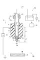
- FIG. 1 is a partially broken schematic view of an electrostatic coating apparatus 100 according to an embodiment of the present invention.
- FIG. 1 is a partially broken schematic view of an electrostatic coating apparatus 100 according to an embodiment of the present invention.
- the electrostatic coating apparatus 100 includes a nozzle unit 10, a counter electrode 20, a power supply 30, a liquid supply unit 40, and a nozzle unit moving unit 50.
- the nozzle unit 10 includes a cylindrical electrode 1, a nozzle 2, and a cover 3.
- the cylindrical electrode 1 is a cylinder provided with an outer flange 1a at the upper end, and the inner diameter D1 is constant.
- the cylindrical electrode 1 is made of, for example, a conductive material such as stainless steel, and forms a first flow path F1 having an inner surface formed of a conductive wall.
- L1 / D1 [ ⁇ ] is 35 or more, preferably 40 or more, more preferably 50 or more.
- the upper limit of L1 / D1 [-] is not particularly limited, but is preferably 100 or less, more preferably 80 or less, and still more preferably 60 or less.
- D1 is preferably 0.5 to 2.0 mm, and more preferably 0.5 to 1.0 mm.
- the length L1 is preferably 20 to 100 mm, more preferably 40 mm or more, and more preferably 80 mm or less.
- the nozzle 2 is provided at the tip of the cylindrical electrode 1.
- the nozzle 2 is made of an electrically insulating material such as glass, ceramic, or resin, and forms a second flow path F2 that communicates with the first flow path F1.
- the inner diameter D2 of the second flow path F2 is smaller than the inner diameter D1 of the first flow path F1.
- D2 is preferably 0.1 to 0.5 mm, and more preferably 0.1 to 0.3 mm.
- the length L2 of the second flow path F2 is not particularly limited, but is preferably smaller than the length of the first flow path F1. Specifically, L2 is preferably 5 to 20 mm, more preferably 5 to 10 mm.
- the outer surface of the lower end of the nozzle 2 has a conical shape. Thereby, a droplet can be discharged toward a board
- the angle formed by the axis and the conical surface is preferably 45 ° or less, and more preferably 35 ° or less.
- a metal support 2s is fixed around the nozzle 2, and the support 2s is inserted into the cylindrical electrode 1 through the O-ring 2b in a state where a part of the nozzle 2 is inserted into the cylindrical electrode 1. It is in contact with the lower end surface.
- the cover 3 has a shape covering the cylindrical electrode 1 and the nozzle 2 and has an opening communicating with the flow path F1 at the top.
- the cover 3 is made of an electrically insulating material such as a resin (PTFE or the like).
- An internal thread is cut on the inner surface of the upper opening of the cover 3 and a pipe joint 4 is connected thereto.
- the pipe joint 4 includes a joint body 4a and a nut 4b that connects the tip of the line L10 to the joint body 4a.
- the counter electrode 20 is disposed on the opposite side of the cylindrical electrode 3 with the nozzle 2 interposed therebetween.
- the counter electrode 20 is arranged on the extension line of the axis of the first flow path F ⁇ b> 1 so as to block the extension line, and is separated from the cylindrical electrode 1 and the nozzle 2.
- the counter electrode 20 is preferably grounded.
- the counter electrode has a plate shape, and the substrate SB to be coated is placed on the counter electrode.
- the power supply 30 applies a voltage between the cylindrical electrode 1 and the counter electrode 20.
- the voltage is a direct current, and for example, it is preferable to supply the voltage in a pulse form.
- the voltage is not particularly limited, but can be 5 to 20 kV in this embodiment.
- the voltage is preferably applied to the counter electrode 20 so that the cylindrical electrode 1 side is positive.
- the liquid supply unit 40 is a device that supplies liquid to the first flow path F1 via the line L10.
- the liquid supply unit 40 includes a tank 41 that stores liquid, and a pump 42 that supplies the resist solution from the tank 41 to the cylindrical electrode 1 via the line L10.
- a pump 42 that supplies the resist solution from the tank 41 to the cylindrical electrode 1 via the line L10.
- the liquid supply unit 40 supplies the resist solution to the first flow path F1.
- the resist solution is a mixture containing a resin such as a novolak resin, a photosensitizer such as naphthodiazide, and a solvent such as PGMEA (propylene-glycol-methyl-ether-acetate).
- a preferable viscosity range of the resist solution is 5 to 1000 mPa ⁇ s.
- Examples of the resist include NPR3510 manufactured by Nagase ChemteX Corporation.
- the nozzle unit moving unit 50 moves the nozzle unit 10 relative to the counter electrode 20.
- the nozzle unit 10 can move independently in two axes in a plane horizontal to the surface of the substrate SB. Thereby, the liquid can be applied to a desired portion on the substrate SB.
- the nozzle unit moving part 50 can move the nozzle unit 10 with respect to the counter electrode 20 also in a direction perpendicular to the substrate SB. Thereby, it is easy to adjust the distance between the tip of the nozzle 2 and the substrate SB.
- the substrate SB to be coated is placed on the counter electrode 20. Subsequently, a voltage is applied between the cylindrical electrode 1 and the counter electrode 20 by the power supply 30. Further, the pump 42 is driven to supply the liquid in the tank 41 to the ends of the first flow path F1 and the second flow path F2 via the line L10. The liquid is charged by being charged by the cylindrical electrode 1, and the liquid protruding from the nozzle 2 forms a Taylor cone, and a charged droplet is ejected from the tip of the cone toward the counter electrode having an opposite charge. The At this time, in this embodiment, since L1 / D1 of the cylindrical electrode 1 is 35 or more, the liquid can be efficiently charged and the droplets can be easily subjected to Rayleigh splitting.
- Rayleigh splitting can be caused even at a voltage of 10 kV or less.
- a liquid resist droplet having a diameter of 3 to 5 ⁇ m can be formed and supplied to a desired portion on the substrate SB.
- a preferred distance between the nozzle 2 and the substrate SB is 10 to 100 mm.
- the present invention is not limited to the above embodiment, and various modifications can be made.
- the nozzle 2 is provided in order to reduce the diameter of the droplet ejected first, but when D1 is as small as 0.1 mm or less, the nozzle 2 is not provided.
- minute droplets can be formed.
- the nozzle 2 is electrically insulative in order to suppress discharge from the nozzle and the like, but the nozzle 2 may be made of a conductive material.
- the nozzle 2 is inserted in the cylindrical electrode 1, it is not limited to this, For example, it implements also in the aspect which the upper end surface of the nozzle 2 contacts the lower end surface of the cylindrical electrode 1. Is possible.
- the inner diameter D1 of the first flow path F1 is constant.
- a tapered tube having an inclination whose inner surface angle with respect to the axis is 15 ° or less in the cross section including the shaft may be used.
- the inner diameter D1 in this case can be defined as an average diameter integrated along the axial direction. The same applies to the second flow path F1 of the nozzle 2.
- the shape of the cylindrical electrode 1 is not particularly limited as long as the first flow path F1 can be formed.
- the flange 1a may be omitted.
- the cover 3 is not essential.
- the line L10 may be directly connected to the cylindrical electrode 1.
- the counter electrode 20 is also plate-shaped, but the shape of the counter electrode 20 can be changed to a desired form according to the shape of the application target.
- the object to be applied is not particularly limited, and for example, the liquid can be applied to various objects such as a substrate having an uneven surface.
- liquid supply part 40 apply
- various liquids besides this.
- a liquid include a polymerizable liquid monomer (for example, 1,9-nonanediol acrylate, 1,1,1) used as a mixed liquid of a non-photosensitive resin and a solvent, a coating liquid for a surface protective film, and the like.
- -Liquid acrylic monomers such as trimethylolpropane triacrylate), metal particle and solvent pastes (silver, gold, copper, etc.), and adhesives.
- the preferred viscosity range of the liquid is 5 to 1000 mPa ⁇ s.
- the solvent is not limited, and various polar solvents and nonpolar solvents such as water and organic solvents can be used.
- the configuration of the liquid supply unit 40 is not particularly limited.
- a configuration in which a pump is connected to the line L1 a configuration in which the pump 42 is a compressed gas source, or a liquid supply amount is small, and the first flow path
- the liquid can be supplied only by the negative pressure or the head difference in F1
- only the line L1 may be used. In short, it is sufficient if the liquid can be supplied to the first flow path F1.
- the voltage at which droplets of 3 to 5 ⁇ m were obtained on the substrate was measured by replacing L1 and D1.
- Resist solution (propylene glycol monomethyl ether acetate (60-80wt%), novolak resin (15-30wt%), naphthoquinone diazide ester ( ⁇ 10wt%), surfactant ( ⁇ 1wt%))
- Cylindrical electrode made of stainless steel, length L1 [mm] of the first flow path F1, inner diameter D1 of the first flow path F1
Landscapes
- Electrostatic Spraying Apparatus (AREA)
- Application Of Or Painting With Fluid Materials (AREA)
- Coating Apparatus (AREA)
Description
前記第一流路の軸線の延長線を遮るように配置された対向電極と、
前記筒状電極と前記対向電極との間に電圧を印加する電源と、
前記第一流路に対して液体を供給する液体供給部と、を備え、
前記第一流路の軸方向長さをL1とし、前記第一流路の内径をD1としたときに、L1/D1が35以上であり、前記第一流路の内径D1は0.5~2.0mmであり、前記第一流路の長さL1は20~100mmである。
例えば、上記実施形態では、最初に射出される液滴の径を小さくすべく、ノズル2が設けられているが、D1が例えば、0.1mm以下程度に小さい場合には、ノズル2が無くても、微少な液滴を形成することができる。

Claims (7)
- 内面が導電性の壁で形成された第一流路を形成する筒状電極と、
前記第一流路の軸線の延長線を遮るように配置された対向電極と、
前記筒状電極と前記対向電極との間に電圧を印加する電源と、
前記第一流路に対して液体を供給する液体供給部と、を備え、
前記第一流路の軸方向長さをL1とし、前記第一流路の内径をD1としたときに、
L1/D1が35以上であり、
前記第一流路の内径D1は0.5~2.0mmであり、
前記第一流路の長さL1は20~100mmである、静電塗布装置。 - 前記第一流路と連通しかつ前記第一流路の内径よりも小さい内径を有する第二流路を形成するノズルをさらに備えた請求項1記載の装置。
- 前記第二流路の内径D2は0.1~0.5mmである請求項2記載の装置。
- 前記ノズルが電気絶縁性である請求項2又は3記載の装置。
- 前記液体供給部は、前記筒状電極の流路にレジスト溶液を供給する請求項1~4のいずれか一項に記載の装置。
- 請求項1~5のいずれか一項に記載の静電塗布装置を用いた、液体の塗布方法。
- 請求項1~5のいずれか一項に記載の静電塗布装置を用い、前記電源から10kV以下の電圧を印加する、液体の塗布方法。
Priority Applications (4)
| Application Number | Priority Date | Filing Date | Title |
|---|---|---|---|
| KR1020147031006A KR101630639B1 (ko) | 2012-05-14 | 2013-05-14 | 정전 도포 장치 및 액체의 도포 방법 |
| US14/401,381 US9630205B2 (en) | 2012-05-14 | 2013-05-14 | Electrostatic application apparatus and method for applying liquid |
| EP13790488.4A EP2851128A4 (en) | 2012-05-14 | 2013-05-14 | ELECTROSTATIC APPLICATION APPARATUS AND LIQUID APPLICATION METHOD |
| CN201380025219.0A CN104284734B (zh) | 2012-05-14 | 2013-05-14 | 静电涂布装置及液体的涂布方法 |
Applications Claiming Priority (2)
| Application Number | Priority Date | Filing Date | Title |
|---|---|---|---|
| JP2012-110933 | 2012-05-14 | ||
| JP2012110933A JP5271437B1 (ja) | 2012-05-14 | 2012-05-14 | 静電塗布装置及び液体の塗布方法 |
Publications (1)
| Publication Number | Publication Date |
|---|---|
| WO2013172356A1 true WO2013172356A1 (ja) | 2013-11-21 |
Family
ID=49179185
Family Applications (1)
| Application Number | Title | Priority Date | Filing Date |
|---|---|---|---|
| PCT/JP2013/063453 Ceased WO2013172356A1 (ja) | 2012-05-14 | 2013-05-14 | 静電塗布装置及び液体の塗布方法 |
Country Status (7)
| Country | Link |
|---|---|
| US (1) | US9630205B2 (ja) |
| EP (1) | EP2851128A4 (ja) |
| JP (1) | JP5271437B1 (ja) |
| KR (1) | KR101630639B1 (ja) |
| CN (1) | CN104284734B (ja) |
| TW (1) | TWI600471B (ja) |
| WO (1) | WO2013172356A1 (ja) |
Cited By (2)
| Publication number | Priority date | Publication date | Assignee | Title |
|---|---|---|---|---|
| CN106000699A (zh) * | 2015-03-25 | 2016-10-12 | 丰田自动车株式会社 | 静电喷嘴、排出装置以及半导体模块的制造方法 |
| WO2026164066A1 (ja) * | 2025-01-28 | 2026-08-06 | アネスト岩田株式会社 | 静電塗布装置及び静電塗布システム |
Families Citing this family (10)
| Publication number | Priority date | Publication date | Assignee | Title |
|---|---|---|---|---|
| JP5833781B1 (ja) * | 2015-03-25 | 2015-12-16 | ナガセテクノエンジニアリング株式会社 | 静電噴霧装置 |
| CN106391363B (zh) * | 2015-07-29 | 2019-04-05 | 清华大学 | 一种多喷头、多通道微滴喷射设备和工艺 |
| JP6657505B2 (ja) | 2015-11-09 | 2020-03-04 | アネスト岩田株式会社 | 静電噴霧装置及び静電噴霧方法 |
| KR101903712B1 (ko) * | 2016-05-12 | 2018-11-30 | 참엔지니어링(주) | 패턴라인 형성장치 |
| JP6463561B1 (ja) * | 2017-03-31 | 2019-02-06 | ナガセテクノエンジニアリング株式会社 | 粒子膜の製造方法、静電噴霧用液、及び、粒子膜 |
| CN109907880B (zh) * | 2019-04-15 | 2021-07-20 | 江苏师范大学 | 眼睛医治用的眼药水滴液系统 |
| JP7394595B2 (ja) * | 2019-11-19 | 2023-12-08 | 花王株式会社 | 静電噴出装置 |
| CN114226092B (zh) * | 2021-12-16 | 2023-04-25 | 蒋恒 | 一种胶水涂覆装置及其使用方法 |
| JP2024018337A (ja) * | 2022-07-29 | 2024-02-08 | アネスト岩田株式会社 | 静電噴霧装置 |
| KR20250146806A (ko) * | 2024-04-02 | 2025-10-13 | 한국과학기술원 | 평면형 정전분무 노즐 모듈 및 이를 이용한 정전분무 장치 |
Citations (4)
| Publication number | Priority date | Publication date | Assignee | Title |
|---|---|---|---|---|
| JP2004136655A (ja) | 2002-09-24 | 2004-05-13 | Konica Minolta Holdings Inc | 液体吐出装置 |
| WO2006011403A1 (ja) * | 2004-07-26 | 2006-02-02 | Konica Minolta Holdings, Inc. | 液体吐出装置 |
| JP2006058628A (ja) | 2004-08-20 | 2006-03-02 | Nippon Dempa Kogyo Co Ltd | レジスト膜の電着機構及びこれを用いた水晶振動子の製造方法 |
| WO2012008459A1 (ja) * | 2010-07-15 | 2012-01-19 | 横浜油脂工業株式会社 | 静電塗装装置 |
Family Cites Families (9)
| Publication number | Priority date | Publication date | Assignee | Title |
|---|---|---|---|---|
| GB8604328D0 (en) * | 1986-02-21 | 1986-03-26 | Ici Plc | Producing spray of droplets of liquid |
| JP2640851B2 (ja) * | 1989-01-17 | 1997-08-13 | ノードソン株式会社 | 液状フォトレジスト剤の塗布方法とその装置 |
| JP2004136652A (ja) | 2002-09-24 | 2004-05-13 | Konica Minolta Holdings Inc | 液体吐出装置 |
| CN2605075Y (zh) | 2003-03-14 | 2004-03-03 | 成都飞亚粉末涂料涂装实业有限公司 | 静电喷涂喷枪 |
| JPWO2006067966A1 (ja) * | 2004-12-20 | 2008-06-12 | コニカミノルタホールディングス株式会社 | 液体吐出ヘッド、液体吐出装置および液体吐出方法 |
| JP2006305321A (ja) * | 2005-03-28 | 2006-11-09 | Matsushita Electric Ind Co Ltd | 空気浄化装置およびそれを利用した空気清浄機および加湿器 |
| JP2007275745A (ja) * | 2006-04-05 | 2007-10-25 | Daikin Ind Ltd | 静電噴霧装置 |
| KR100920769B1 (ko) | 2008-03-11 | 2009-10-08 | 연세대학교 산학협력단 | 전기수력학적 분사노즐, 이를 이용한 분사장치 및패터닝방법 |
| KR20130125287A (ko) | 2010-05-29 | 2013-11-18 | 애쉴리 에스. 스코트 | 정전기 유도 용매 분출 또는 입자 형성을 위한 장치, 방법 및 유체 조성물 |
-
2012
- 2012-05-14 JP JP2012110933A patent/JP5271437B1/ja active Active
-
2013
- 2013-05-14 TW TW102117036A patent/TWI600471B/zh active
- 2013-05-14 CN CN201380025219.0A patent/CN104284734B/zh active Active
- 2013-05-14 EP EP13790488.4A patent/EP2851128A4/en not_active Withdrawn
- 2013-05-14 KR KR1020147031006A patent/KR101630639B1/ko active Active
- 2013-05-14 WO PCT/JP2013/063453 patent/WO2013172356A1/ja not_active Ceased
- 2013-05-14 US US14/401,381 patent/US9630205B2/en active Active
Patent Citations (4)
| Publication number | Priority date | Publication date | Assignee | Title |
|---|---|---|---|---|
| JP2004136655A (ja) | 2002-09-24 | 2004-05-13 | Konica Minolta Holdings Inc | 液体吐出装置 |
| WO2006011403A1 (ja) * | 2004-07-26 | 2006-02-02 | Konica Minolta Holdings, Inc. | 液体吐出装置 |
| JP2006058628A (ja) | 2004-08-20 | 2006-03-02 | Nippon Dempa Kogyo Co Ltd | レジスト膜の電着機構及びこれを用いた水晶振動子の製造方法 |
| WO2012008459A1 (ja) * | 2010-07-15 | 2012-01-19 | 横浜油脂工業株式会社 | 静電塗装装置 |
Non-Patent Citations (1)
| Title |
|---|
| See also references of EP2851128A4 |
Cited By (3)
| Publication number | Priority date | Publication date | Assignee | Title |
|---|---|---|---|---|
| CN106000699A (zh) * | 2015-03-25 | 2016-10-12 | 丰田自动车株式会社 | 静电喷嘴、排出装置以及半导体模块的制造方法 |
| US10236188B2 (en) | 2015-03-25 | 2019-03-19 | Toyota Jidosha Kabushiki Kaisha | Electrostatic nozzle, discharge apparatus, and method for manufacturing semiconductor module |
| WO2026164066A1 (ja) * | 2025-01-28 | 2026-08-06 | アネスト岩田株式会社 | 静電塗布装置及び静電塗布システム |
Also Published As
| Publication number | Publication date |
|---|---|
| KR101630639B1 (ko) | 2016-06-15 |
| CN104284734B (zh) | 2018-06-08 |
| TW201412405A (zh) | 2014-04-01 |
| TWI600471B (zh) | 2017-10-01 |
| CN104284734A (zh) | 2015-01-14 |
| US20150125619A1 (en) | 2015-05-07 |
| EP2851128A1 (en) | 2015-03-25 |
| EP2851128A4 (en) | 2015-12-30 |
| KR20150013492A (ko) | 2015-02-05 |
| JP2013237002A (ja) | 2013-11-28 |
| US9630205B2 (en) | 2017-04-25 |
| JP5271437B1 (ja) | 2013-08-21 |
Similar Documents
| Publication | Publication Date | Title |
|---|---|---|
| JP5271437B1 (ja) | 静電塗布装置及び液体の塗布方法 | |
| CN1104965C (zh) | 用于喷射液滴的装置和方法 | |
| US10946407B2 (en) | Apparatus and method for atomization of fluid | |
| US10618067B2 (en) | Electrostatic spray device and electrostatic spray method | |
| CN1006447B (zh) | 静电喷雾 | |
| JP2016114400A (ja) | マトリックス膜形成装置 | |
| CN112454883A (zh) | 一种低温辅助电喷印方法 | |
| WO2006067966A1 (ja) | 液体吐出ヘッド、液体吐出装置および液体吐出方法 | |
| JP2024091756A (ja) | マスキング治具 | |
| CN110681505B (zh) | 一种电喷雾装置 | |
| WO2023016072A1 (zh) | 一种电流体多喷头装置 | |
| CN107584885B (zh) | 喷头及其驱动方法、喷墨装置 | |
| JP5802787B1 (ja) | 液塗布方法、及び、液塗布装置 | |
| JP5833781B1 (ja) | 静電噴霧装置 | |
| WO2014077362A1 (ja) | 静電噴霧用液調製用溶媒、静電噴霧用液、及び、静電噴霧方法 | |
| JP5607849B1 (ja) | 液塗布方法、及び、液塗布装置 | |
| JP4807060B2 (ja) | ノズルプレート、ノズルプレートの製造方法及び液体吐出ヘッド | |
| Kachkine | Additively Manufacturing High-Performance, Low-Cost Electrospray Ion Sources for Point-of-Care Mass Spectrometry | |
| JP2015115462A (ja) | 塗布装置および塗布方法 | |
| JP7729531B2 (ja) | コーティング方法 | |
| JP2007216461A (ja) | 液体吐出装置及び液体吐出方法 | |
| CN113560058B (zh) | 一种稳定多股射流模式的阵列集成静电雾化装置及实验系统 | |
| US20170014840A1 (en) | Electrostatic coating device, power source device for electrostatic coating device and electrostatic coating method | |
| JP2004160287A (ja) | 成膜装置および成膜方法 | |
| JP6463561B1 (ja) | 粒子膜の製造方法、静電噴霧用液、及び、粒子膜 |
Legal Events
| Date | Code | Title | Description |
|---|---|---|---|
| 121 | Ep: the epo has been informed by wipo that ep was designated in this application |
Ref document number: 13790488 Country of ref document: EP Kind code of ref document: A1 |
|
| WWE | Wipo information: entry into national phase |
Ref document number: 2013790488 Country of ref document: EP |
|
| ENP | Entry into the national phase |
Ref document number: 20147031006 Country of ref document: KR Kind code of ref document: A |
|
| NENP | Non-entry into the national phase |
Ref country code: DE |
|
| WWE | Wipo information: entry into national phase |
Ref document number: 14401381 Country of ref document: US |