WO2013172463A1 - 車両の制御装置、及びそれを備える自動二輪車 - Google Patents
車両の制御装置、及びそれを備える自動二輪車 Download PDFInfo
- Publication number
- WO2013172463A1 WO2013172463A1 PCT/JP2013/063852 JP2013063852W WO2013172463A1 WO 2013172463 A1 WO2013172463 A1 WO 2013172463A1 JP 2013063852 W JP2013063852 W JP 2013063852W WO 2013172463 A1 WO2013172463 A1 WO 2013172463A1
- Authority
- WO
- WIPO (PCT)
- Prior art keywords
- target
- target value
- driving force
- vehicle
- speed
- Prior art date
- Legal status (The legal status is an assumption and is not a legal conclusion. Google has not performed a legal analysis and makes no representation as to the accuracy of the status listed.)
- Ceased
Links
Images










Classifications
-
- B—PERFORMING OPERATIONS; TRANSPORTING
- B60—VEHICLES IN GENERAL
- B60W—CONJOINT CONTROL OF VEHICLE SUB-UNITS OF DIFFERENT TYPE OR DIFFERENT FUNCTION; CONTROL SYSTEMS SPECIALLY ADAPTED FOR HYBRID VEHICLES; ROAD VEHICLE DRIVE CONTROL SYSTEMS FOR PURPOSES NOT RELATED TO THE CONTROL OF A PARTICULAR SUB-UNIT
- B60W10/00—Conjoint control of vehicle sub-units of different type or different function
- B60W10/10—Conjoint control of vehicle sub-units of different type or different function including control of change-speed gearings
- B60W10/101—Infinitely variable gearings
- B60W10/107—Infinitely variable gearings with endless flexible members
-
- B—PERFORMING OPERATIONS; TRANSPORTING
- B60—VEHICLES IN GENERAL
- B60W—CONJOINT CONTROL OF VEHICLE SUB-UNITS OF DIFFERENT TYPE OR DIFFERENT FUNCTION; CONTROL SYSTEMS SPECIALLY ADAPTED FOR HYBRID VEHICLES; ROAD VEHICLE DRIVE CONTROL SYSTEMS FOR PURPOSES NOT RELATED TO THE CONTROL OF A PARTICULAR SUB-UNIT
- B60W10/00—Conjoint control of vehicle sub-units of different type or different function
- B60W10/04—Conjoint control of vehicle sub-units of different type or different function including control of propulsion units
- B60W10/06—Conjoint control of vehicle sub-units of different type or different function including control of propulsion units including control of combustion engines
-
- B—PERFORMING OPERATIONS; TRANSPORTING
- B60—VEHICLES IN GENERAL
- B60W—CONJOINT CONTROL OF VEHICLE SUB-UNITS OF DIFFERENT TYPE OR DIFFERENT FUNCTION; CONTROL SYSTEMS SPECIALLY ADAPTED FOR HYBRID VEHICLES; ROAD VEHICLE DRIVE CONTROL SYSTEMS FOR PURPOSES NOT RELATED TO THE CONTROL OF A PARTICULAR SUB-UNIT
- B60W30/00—Purposes of road vehicle drive control systems not related to the control of a particular sub-unit, e.g. of systems using conjoint control of vehicle sub-units
- B60W30/18—Propelling the vehicle
- B60W30/188—Controlling power parameters of the driveline, e.g. determining the required power
- B60W30/1882—Controlling power parameters of the driveline, e.g. determining the required power characterised by the working point of the engine, e.g. by using engine output chart
-
- B—PERFORMING OPERATIONS; TRANSPORTING
- B60—VEHICLES IN GENERAL
- B60W—CONJOINT CONTROL OF VEHICLE SUB-UNITS OF DIFFERENT TYPE OR DIFFERENT FUNCTION; CONTROL SYSTEMS SPECIALLY ADAPTED FOR HYBRID VEHICLES; ROAD VEHICLE DRIVE CONTROL SYSTEMS FOR PURPOSES NOT RELATED TO THE CONTROL OF A PARTICULAR SUB-UNIT
- B60W40/00—Estimation or calculation of non-directly measurable driving parameters for road vehicle drive control systems not related to the control of a particular sub unit, e.g. by using mathematical models
- B60W40/10—Estimation or calculation of non-directly measurable driving parameters for road vehicle drive control systems not related to the control of a particular sub unit, e.g. by using mathematical models related to vehicle motion
- B60W40/1005—Driving resistance
-
- F—MECHANICAL ENGINEERING; LIGHTING; HEATING; WEAPONS; BLASTING
- F02—COMBUSTION ENGINES; HOT-GAS OR COMBUSTION-PRODUCT ENGINE PLANTS
- F02D—CONTROLLING COMBUSTION ENGINES
- F02D31/00—Use of speed-sensing governors to control combustion engines, not otherwise provided for
- F02D31/001—Electric control of rotation speed
- F02D31/002—Electric control of rotation speed controlling air supply
-
- F—MECHANICAL ENGINEERING; LIGHTING; HEATING; WEAPONS; BLASTING
- F02—COMBUSTION ENGINES; HOT-GAS OR COMBUSTION-PRODUCT ENGINE PLANTS
- F02D—CONTROLLING COMBUSTION ENGINES
- F02D41/00—Electrical control of supply of combustible mixture or its constituents
- F02D41/0002—Controlling intake air
-
- B—PERFORMING OPERATIONS; TRANSPORTING
- B60—VEHICLES IN GENERAL
- B60W—CONJOINT CONTROL OF VEHICLE SUB-UNITS OF DIFFERENT TYPE OR DIFFERENT FUNCTION; CONTROL SYSTEMS SPECIALLY ADAPTED FOR HYBRID VEHICLES; ROAD VEHICLE DRIVE CONTROL SYSTEMS FOR PURPOSES NOT RELATED TO THE CONTROL OF A PARTICULAR SUB-UNIT
- B60W50/00—Details of control systems for road vehicle drive control not related to the control of a particular sub-unit, e.g. process diagnostic or vehicle driver interfaces
- B60W2050/0001—Details of the control system
- B60W2050/0019—Control system elements or transfer functions
- B60W2050/0022—Gains, weighting coefficients or weighting functions
-
- B—PERFORMING OPERATIONS; TRANSPORTING
- B60—VEHICLES IN GENERAL
- B60W—CONJOINT CONTROL OF VEHICLE SUB-UNITS OF DIFFERENT TYPE OR DIFFERENT FUNCTION; CONTROL SYSTEMS SPECIALLY ADAPTED FOR HYBRID VEHICLES; ROAD VEHICLE DRIVE CONTROL SYSTEMS FOR PURPOSES NOT RELATED TO THE CONTROL OF A PARTICULAR SUB-UNIT
- B60W50/00—Details of control systems for road vehicle drive control not related to the control of a particular sub-unit, e.g. process diagnostic or vehicle driver interfaces
- B60W2050/0001—Details of the control system
- B60W2050/0043—Signal treatments, identification of variables or parameters, parameter estimation or state estimation
- B60W2050/0052—Filtering, filters
-
- B—PERFORMING OPERATIONS; TRANSPORTING
- B60—VEHICLES IN GENERAL
- B60W—CONJOINT CONTROL OF VEHICLE SUB-UNITS OF DIFFERENT TYPE OR DIFFERENT FUNCTION; CONTROL SYSTEMS SPECIALLY ADAPTED FOR HYBRID VEHICLES; ROAD VEHICLE DRIVE CONTROL SYSTEMS FOR PURPOSES NOT RELATED TO THE CONTROL OF A PARTICULAR SUB-UNIT
- B60W50/00—Details of control systems for road vehicle drive control not related to the control of a particular sub-unit, e.g. process diagnostic or vehicle driver interfaces
- B60W2050/0001—Details of the control system
- B60W2050/0043—Signal treatments, identification of variables or parameters, parameter estimation or state estimation
- B60W2050/0052—Filtering, filters
- B60W2050/0054—Cut-off filters, retarders, delaying means, dead zones, threshold values or cut-off frequency
- B60W2050/0056—Low-pass filters
-
- B—PERFORMING OPERATIONS; TRANSPORTING
- B60—VEHICLES IN GENERAL
- B60W—CONJOINT CONTROL OF VEHICLE SUB-UNITS OF DIFFERENT TYPE OR DIFFERENT FUNCTION; CONTROL SYSTEMS SPECIALLY ADAPTED FOR HYBRID VEHICLES; ROAD VEHICLE DRIVE CONTROL SYSTEMS FOR PURPOSES NOT RELATED TO THE CONTROL OF A PARTICULAR SUB-UNIT
- B60W2300/00—Indexing codes relating to the type of vehicle
- B60W2300/36—Cycles; Motorcycles; Scooters
-
- B—PERFORMING OPERATIONS; TRANSPORTING
- B60—VEHICLES IN GENERAL
- B60W—CONJOINT CONTROL OF VEHICLE SUB-UNITS OF DIFFERENT TYPE OR DIFFERENT FUNCTION; CONTROL SYSTEMS SPECIALLY ADAPTED FOR HYBRID VEHICLES; ROAD VEHICLE DRIVE CONTROL SYSTEMS FOR PURPOSES NOT RELATED TO THE CONTROL OF A PARTICULAR SUB-UNIT
- B60W2520/00—Input parameters relating to overall vehicle dynamics
- B60W2520/10—Longitudinal speed
-
- B—PERFORMING OPERATIONS; TRANSPORTING
- B60—VEHICLES IN GENERAL
- B60W—CONJOINT CONTROL OF VEHICLE SUB-UNITS OF DIFFERENT TYPE OR DIFFERENT FUNCTION; CONTROL SYSTEMS SPECIALLY ADAPTED FOR HYBRID VEHICLES; ROAD VEHICLE DRIVE CONTROL SYSTEMS FOR PURPOSES NOT RELATED TO THE CONTROL OF A PARTICULAR SUB-UNIT
- B60W2540/00—Input parameters relating to occupants
- B60W2540/10—Accelerator pedal position
-
- B—PERFORMING OPERATIONS; TRANSPORTING
- B60—VEHICLES IN GENERAL
- B60W—CONJOINT CONTROL OF VEHICLE SUB-UNITS OF DIFFERENT TYPE OR DIFFERENT FUNCTION; CONTROL SYSTEMS SPECIALLY ADAPTED FOR HYBRID VEHICLES; ROAD VEHICLE DRIVE CONTROL SYSTEMS FOR PURPOSES NOT RELATED TO THE CONTROL OF A PARTICULAR SUB-UNIT
- B60W2710/00—Output or target parameters relating to a particular sub-units
- B60W2710/06—Combustion engines, Gas turbines
- B60W2710/0605—Throttle position
-
- B—PERFORMING OPERATIONS; TRANSPORTING
- B60—VEHICLES IN GENERAL
- B60W—CONJOINT CONTROL OF VEHICLE SUB-UNITS OF DIFFERENT TYPE OR DIFFERENT FUNCTION; CONTROL SYSTEMS SPECIALLY ADAPTED FOR HYBRID VEHICLES; ROAD VEHICLE DRIVE CONTROL SYSTEMS FOR PURPOSES NOT RELATED TO THE CONTROL OF A PARTICULAR SUB-UNIT
- B60W2710/00—Output or target parameters relating to a particular sub-units
- B60W2710/06—Combustion engines, Gas turbines
- B60W2710/0644—Engine speed
-
- B—PERFORMING OPERATIONS; TRANSPORTING
- B60—VEHICLES IN GENERAL
- B60W—CONJOINT CONTROL OF VEHICLE SUB-UNITS OF DIFFERENT TYPE OR DIFFERENT FUNCTION; CONTROL SYSTEMS SPECIALLY ADAPTED FOR HYBRID VEHICLES; ROAD VEHICLE DRIVE CONTROL SYSTEMS FOR PURPOSES NOT RELATED TO THE CONTROL OF A PARTICULAR SUB-UNIT
- B60W2710/00—Output or target parameters relating to a particular sub-units
- B60W2710/10—Change speed gearings
- B60W2710/1005—Transmission ratio engaged
-
- B—PERFORMING OPERATIONS; TRANSPORTING
- B60—VEHICLES IN GENERAL
- B60W—CONJOINT CONTROL OF VEHICLE SUB-UNITS OF DIFFERENT TYPE OR DIFFERENT FUNCTION; CONTROL SYSTEMS SPECIALLY ADAPTED FOR HYBRID VEHICLES; ROAD VEHICLE DRIVE CONTROL SYSTEMS FOR PURPOSES NOT RELATED TO THE CONTROL OF A PARTICULAR SUB-UNIT
- B60W2710/00—Output or target parameters relating to a particular sub-units
- B60W2710/10—Change speed gearings
- B60W2710/105—Output torque
-
- B—PERFORMING OPERATIONS; TRANSPORTING
- B60—VEHICLES IN GENERAL
- B60Y—INDEXING SCHEME RELATING TO ASPECTS CROSS-CUTTING VEHICLE TECHNOLOGY
- B60Y2200/00—Type of vehicle
- B60Y2200/10—Road Vehicles
- B60Y2200/12—Motorcycles, Trikes; Quads; Scooters
- B60Y2200/126—Scooters
-
- F—MECHANICAL ENGINEERING; LIGHTING; HEATING; WEAPONS; BLASTING
- F02—COMBUSTION ENGINES; HOT-GAS OR COMBUSTION-PRODUCT ENGINE PLANTS
- F02D—CONTROLLING COMBUSTION ENGINES
- F02D2200/00—Input parameters for engine control
- F02D2200/50—Input parameters for engine control said parameters being related to the vehicle or its components
- F02D2200/501—Vehicle speed
-
- F—MECHANICAL ENGINEERING; LIGHTING; HEATING; WEAPONS; BLASTING
- F02—COMBUSTION ENGINES; HOT-GAS OR COMBUSTION-PRODUCT ENGINE PLANTS
- F02D—CONTROLLING COMBUSTION ENGINES
- F02D2200/00—Input parameters for engine control
- F02D2200/60—Input parameters for engine control said parameters being related to the driver demands or status
- F02D2200/602—Pedal position
-
- F—MECHANICAL ENGINEERING; LIGHTING; HEATING; WEAPONS; BLASTING
- F02—COMBUSTION ENGINES; HOT-GAS OR COMBUSTION-PRODUCT ENGINE PLANTS
- F02D—CONTROLLING COMBUSTION ENGINES
- F02D2250/00—Engine control related to specific problems or objectives
- F02D2250/18—Control of the engine output torque
-
- F—MECHANICAL ENGINEERING; LIGHTING; HEATING; WEAPONS; BLASTING
- F02—COMBUSTION ENGINES; HOT-GAS OR COMBUSTION-PRODUCT ENGINE PLANTS
- F02D—CONTROLLING COMBUSTION ENGINES
- F02D41/00—Electrical control of supply of combustible mixture or its constituents
- F02D41/02—Circuit arrangements for generating control signals
- F02D41/021—Introducing corrections for particular conditions exterior to the engine
- F02D41/0215—Introducing corrections for particular conditions exterior to the engine in relation with elements of the transmission
- F02D41/0225—Introducing corrections for particular conditions exterior to the engine in relation with elements of the transmission in relation with the gear ratio or shift lever position
-
- Y—GENERAL TAGGING OF NEW TECHNOLOGICAL DEVELOPMENTS; GENERAL TAGGING OF CROSS-SECTIONAL TECHNOLOGIES SPANNING OVER SEVERAL SECTIONS OF THE IPC; TECHNICAL SUBJECTS COVERED BY FORMER USPC CROSS-REFERENCE ART COLLECTIONS [XRACs] AND DIGESTS
- Y02—TECHNOLOGIES OR APPLICATIONS FOR MITIGATION OR ADAPTATION AGAINST CLIMATE CHANGE
- Y02T—CLIMATE CHANGE MITIGATION TECHNOLOGIES RELATED TO TRANSPORTATION
- Y02T10/00—Road transport of goods or passengers
- Y02T10/10—Internal combustion engine [ICE] based vehicles
- Y02T10/40—Engine management systems
Definitions
- the present invention relates to a vehicle control device that electronically controls both the opening of an engine throttle valve and the transmission of a continuously variable transmission.
- a vehicle control device that electronically controls a transmission ratio of a continuously variable transmission and a throttle valve opening (throttle opening) (for example, Japanese Patent No. 3754188).
- the required driving force is calculated based on the amount of accelerator operation (accelerator operation amount) by the driver and the vehicle speed.
- the target engine speed and the target throttle opening are calculated so that this required driving force can be obtained.
- the target engine speed the speed with the highest fuel efficiency is set.
- the influence of engine speed on the feeling of riding is greater than that of a four-wheeled vehicle, so there is a strong demand to set the engine speed to a speed that achieves a comfortable riding feeling.
- the required driving force is set first, and thereafter, the rotational speed at which the required driving force is obtained and the fuel efficiency is the highest is set as the target engine rotational speed.
- the target engine speed is affected by the required driving force, it is difficult to control the target engine speed. As a result, it is difficult to achieve a comfortable ride.
- An object of the present invention is to provide a vehicle control device and a motorcycle that can relatively easily set the engine speed to a speed that achieves a comfortable ride.
- the control device controls the gear ratio and throttle opening of the continuously variable transmission.
- the control device includes: a target engine speed calculation unit that calculates a target engine speed; a target speed ratio calculation unit that calculates a target speed ratio based on the target engine speed; an accelerator operation amount detected by a sensor; Based on the target engine speed, a driving force target calculation unit that calculates a driving force target value that is a target value related to the driving force of the vehicle, and the driving so that a driving force corresponding to the driving force target value is obtained.
- a target throttle opening calculation unit that calculates a target throttle opening that is a target throttle opening based on the force target value and the target engine speed;
- a motorcycle according to the present invention includes the control device.
- the target engine speed is calculated first, and then the driving force target value is calculated. Therefore, the engine speed is set to a speed at which a comfortable riding feeling can be realized. Easy to do.
- the driving force target value that is a target value relating to the driving force of the vehicle is, for example, a target for engine torque and engine output, a target for driving wheel torque and driving wheel power, and a vehicle.
- the product of vehicle acceleration and vehicle weight is the driving force of the vehicle.
- a map that associates the accelerator operation amount with the engine speed is used. This map is not limited to a map that directly associates the accelerator operation amount and the engine speed, but may be a map that associates them indirectly. That is, the map may include a map that associates the accelerator operation amount with the throttle opening, and a map that associates the throttle opening with the engine speed.
- the target engine speed calculation unit may calculate an engine speed higher than the engine speed at which fuel efficiency is optimal as the target engine speed. According to this, the acceleration responsiveness of the vehicle can be improved.
- the driving force target calculation unit may perform a correction process on the driving force target value, and the target throttle opening calculation unit may calculate the target throttle opening based on the corrected driving force target value. According to this, it becomes possible to correct the driving force target value as necessary, and the acceleration of the vehicle can be improved.
- the driving force target calculation unit may correct the driving force target value using a filter function. According to this, the relative change of the corrected driving force target value with respect to the uncorrected driving force target value can be made desirable.
- the filter function may be defined such that the rising speed of the corrected driving force target value is smaller than the rising speed of the reference driving force target value before correction. According to this, smooth acceleration and / or deceleration can be realized.
- the corrected driving force target value rises to a value higher than the driving force target value before correction, and then toward the driving force target value before correction.
- the filter function may be defined such that According to this, acceleration performance can be improved and acceleration feeling can be maintained.
- the transfer function of the filter function may include a first-order lag element. According to this, according to this, smooth acceleration and / or deceleration can be realized.
- the transfer function of the filter function may include a proportional element. According to this, acceleration performance can be improved.
- the driving force target calculation unit performs a correction to increase the driving force target value when the driving force target value before correction is larger than a reference driving resistance that is a running resistance received when the vehicle is traveling at a constant vehicle speed. May be.
- the correction using the correction coefficient is performed from the start of acceleration until the vehicle travels at a constant vehicle speed (hereinafter, steady travel), and a more comfortable acceleration performance is obtained. Further, after the vehicle reaches steady running, correction using the correction coefficient is not performed, so that the behavior of the vehicle matches the accelerator operation, and steady running can be made more comfortable.
- the driving force target calculation unit may calculate the driving force target value based on a traveling load acting on the vehicle. According to this, for example, when traveling on a slope, correction according to the gradient can be performed.
- the control device includes a traveling load estimation unit that estimates a traveling load, and when the estimated traveling load is smaller than a predetermined threshold, correction of the driving force target value based on the traveling load is limited. Good. According to this, even when it is difficult to estimate the travel load with high accuracy, it is possible to suppress the correction based on the travel load from being performed in an inappropriate situation.
- the correction of the driving force target value may be limited when the vehicle speed is a predetermined value or less. According to this, when the vehicle approaches a stop, it can suppress that the driving force of a vehicle increases by correction
- the correction of the driving force target value may be limited when the accelerator operation amount is equal to or less than a predetermined value. According to this, when the rider intends to stop the vehicle and the accelerator operation amount is reduced, it is possible to suppress an increase in the driving force of the vehicle due to the correction.
- the driving force target value is a target value related to torque of the driving wheel
- the driving force target calculation unit is based on an engine torque target value that is a target value related to engine torque and an inertia torque generated by a change in engine speed.
- the driving force target value may be calculated. According to this, it becomes possible to set the target throttle opening that compensates for the loss of driving force due to the generation of inertia torque.
- 1 is a side view of a motorcycle including a control device according to an embodiment of the present invention.
- 1 is a block diagram showing a configuration of a motorcycle. It is a figure for demonstrating the outline
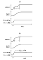
- FIG. 5A is a time chart in which both the conversion unit and the inverse conversion unit use inertia torque
- FIG. 5A is a time chart in which both the conversion unit and the inverse conversion unit use inertia torque
- FIG. 5B is a time chart in which only the inverse conversion unit uses inertia torque. It is a block diagram which shows the modification of a control apparatus. It is a block diagram which shows the modification of a control apparatus. It is a figure which shows the modification of the process which a driving force target value calculation part performs. It is a figure which shows the example of the relationship between the reference
- FIG. 4A is a diagram showing an example of the relationship between the vehicle speed and the vehicle speed coefficient.
- 5B is a diagram showing an example of the relationship between the accelerator operation amount and the accelerator coefficient. It is a figure which shows the example of the relationship between the correction coefficient which the 1st correction
- FIG. 1 is a side view of a motorcycle 1 including a control device 10 according to an embodiment of the present invention.
- FIG. 2 is a block diagram showing the configuration of the motorcycle 1.
- the motorcycle 1 has a front wheel 2 and a handle 3 for steering the front wheel 2 left and right at the front thereof.
- the handle 3 is provided with an accelerator grip 3a (see FIG. 2).
- the accelerator grip 3a is provided with an accelerator sensor 24 for detecting an operation amount (accelerator operation amount) of the accelerator grip 3a.
- the motorcycle 1 has an engine 4.
- the motorcycle 1 has a continuously variable transmission (hereinafter referred to as CVT) 5, a clutch 6, and a final reduction mechanism 7 on a torque transmission path from the engine 4 to the rear wheel 8 that is a driving wheel.
- CVT 5 is disposed downstream of the engine 4 and the clutch 6 is disposed downstream of the CVT 5.
- a final reduction mechanism 7 is disposed between the clutch 6 and the rear wheel 8.
- the motorcycle 1 has a vehicle speed sensor 27 for detecting the vehicle speed.
- the vehicle speed sensor 27 is provided on the rear wheel 8 or the front wheel 2. Further, the vehicle speed sensor 27 may be provided in the final reduction mechanism 7 or the clutch 6.
- the engine 4 has a cylinder, a piston disposed in the cylinder, a crankshaft connected to the piston, and the like.
- the motorcycle 1 has an engine speed sensor 21 for detecting the engine speed.
- the engine 4 also has a throttle valve that controls the amount of air supplied to the engine 4 and an injector that injects fuel toward the intake passage in an intake passage connected to the combustion chamber.
- the injector injects an amount of fuel corresponding to the amount of air supplied to the engine, that is, an amount corresponding to the opening of the throttle valve (hereinafter referred to as throttle opening).
- the motorcycle 1 has a throttle opening sensor 22 for detecting the throttle opening, and a throttle actuator 23 for controlling the opening of the throttle valve.
- the CVT 5 is stretched over an input shaft interlocked with the crankshaft, a driving pulley disposed on the input shaft, an output shaft, a driven pulley disposed on the output shaft, a driving pulley and a driven pulley. And a belt for transmitting the rotation (torque) of the driving pulley to the driven pulley.
- the motorcycle 1 has a CVT actuator 25 for controlling the transmission ratio of the CVT 5.
- the CVT actuator 25 controls one of the two sheaves constituting the drive pulley to control the gear ratio.
- the CVT actuator 25 may control the gear ratio by moving one of the two sheaves constituting the driven pulley.
- the CVT 5 is provided with an output shaft rotation sensor 26 for detecting the rotation speed of the output shaft of the CVT 5.
- the motorcycle 1 includes a control device 10.
- Output signals from the sensors 21, 22, 24, 26, and 27 are input to the control device 10.
- the actuators 23 and 25 described above are driven according to the output signal of the control device 10.
- the control device 10 controls the engine 4 and the CVT 5 based on the outputs of the sensors 21, 22, 24, 26, and 27. Particularly in the present embodiment, the control device 10 controls the transmission ratio of the CVT 5 through the CVT actuator 25. Further, the control device 10 controls the throttle opening through the throttle actuator 23.
- the control device 10 first calculates a target engine speed based on the accelerator operation amount detected by the accelerator sensor 24.
- the control device 10 calculates a target gear ratio (target gear ratio) and a target throttle opening (target throttle opening) based on the target engine speed.
- Control device 10 drives actuators 23 and 25 so that the actual transmission ratio of CVT 5 and the actual throttle opening are the target transmission ratio and the target throttle opening, respectively.
- the processing executed by the control device 10 will be described in detail later.
- the control device 10 of this example includes an engine control device 10a and a CVT control device 10b as shown in FIG.
- Each of the control devices 10a and 10b includes a storage device 10c and a microprocessor that executes a program stored in the storage device 10c.
- the storage device 10c stores a map used for controlling the engine 4 and the CVT 5.
- the two control devices 10a and 10b are connected to each other and communicate according to a predefined protocol.
- One control device 10a, 10b receives data about the operating state of the motorcycle 1 detected by the sensors 21, 22, 24, 26, 27, and processing results by the one control device 10a, 10b. 10b and 10a are notified.
- the outputs of the engine speed sensor 21, the throttle opening sensor 22, and the accelerator sensor 24 are input to the engine control device 10a.
- the engine control device 10a notifies the CVT control device 10b of the rotation speed and the throttle opening detected by these sensors 21, 22, and 24.
- the outputs of the output shaft rotation sensor 26 and the vehicle speed sensor 27 are input to the CVT control device 10b.
- the CVT control device 10b uses the rotation speed and vehicle speed detected by these sensors 26 and 27, and the processing results of the CVT control device 10b (for example, the target engine speed and target speed ratio obtained by the processing described later), Notify the engine control device 10a.
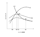
- FIG. 3 is a diagram for explaining an outline of control.
- the horizontal axis represents the engine speed
- the vertical axis represents the engine torque.
- two torque curves representing the relationship between the engine torque and the engine speed are drawn.
- the two torque curves are a torque curve when the throttle opening is Th1 and a torque curve when the throttle opening is Th2.
- a line A is a curve (hereinafter referred to as the best fuel consumption curve) indicating an operation point at which the fuel consumption becomes the best.
- the control device 10 in this example has three control modes.
- the first mode is a fuel consumption mode
- the second mode is a normal mode
- the third mode is a comfortable driving mode.
- the control device 10 performs a reference target engine speed (hereinafter referred to as a reference target engine speed) based on a throttle opening (hereinafter referred to as a reference throttle opening) corresponding to an accelerator operation amount detected by the accelerator sensor 24. Is calculated.
- the throttle opening degree Th1 is a reference throttle opening degree corresponding to the accelerator operation amount
- the engine speed N1 is a reference target engine speed.
- the control device 10 sets a rotational speed lower than the reference target engine speed N1 as a target engine speed (hereinafter referred to as a final target engine speed).
- the control device 10 sets, as the final target engine speed, the engine speed N2 that is close to the engine speed N3 shown in FIG. 3 from the reference target engine speed N1.
- the engine speed N3 can obtain the same engine output (engine torque ⁇ engine speed) as the operating point P1 (engine speed N1, reference throttle opening Th1), and driving on the best fuel consumption curve A. This is the engine speed at point P3.
- a line L3 is an equal output curve showing an operation point at which the same engine output as that of the operation point P1 can be obtained.
- control device 10 reduces the final target engine speed relative to the reference target engine speed N1, while maintaining the driving force (for example, the torque of the rear wheels 8) obtained at the driving point P1.
- the control device 10 can obtain a driving force equal to the operating point P1, and sets the throttle opening Th2 at the operating point P2 at which the engine speed becomes the final target engine speed N2 as the target throttle opening.
- the torque of the rear wheel 8 is proportional to the engine output. Therefore, the operation point P2 is an operation point on the equal output curve L3.
- the above is the outline of the fuel consumption mode.
- the control device 10 calculates a reference target engine speed N1 based on the reference throttle opening Th1. In the normal mode, the control device 10 sets the target engine speed N1 as the final target engine speed. The control device 10 calculates the target gear ratio from the target engine speed N1. Further, the control device 10 sets the reference throttle opening Th1 as the target throttle opening.
- the control device 10 calculates a reference target engine speed N1 based on the reference throttle opening Th1.
- the target engine speed N1 is set as the final target engine speed
- the target gear ratio is calculated from the target engine speed N1.
- the control device 10 sets a target value (hereinafter referred to as a reference drive wheel torque) for a driving force of the vehicle (for example, torque of the rear wheel 8, hereinafter referred to as rear wheel torque).
- a target value hereinafter referred to as a reference drive wheel torque
- the control device 10 filters the reference driving wheel torque target value, and the result is expressed as a final driving wheel torque target value (below).
- Final driving wheel torque target value This filter is set so that the final drive wheel torque target value changes more slowly than the reference drive wheel torque target value.
- the control device 10 calculates the target throttle opening from the final drive wheel torque target value.
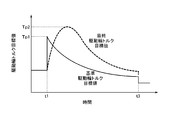
- FIG. 4 is a time chart for explaining the temporal change of the final drive wheel torque target value.
- Time t1 in the figure is the time when the accelerator operation amount increases and the driver's acceleration request satisfies a preset correction condition.
- Time t3 is a point in time when the accelerator operation amount is reduced and the acceleration request no longer satisfies the preset correction condition.
- the reference driving wheel torque target value suddenly increases at time t1 due to the increase in the accelerator operation amount, and then gradually decreases.
- the final drive wheel torque target value gradually increases to a value Tp2 higher than the peak value Tp1 of the reference drive wheel torque target value. Thereafter, the final driving wheel torque target value is gradually lowered from the reference driving wheel torque target value.
- the control device 10 calculates the target throttle opening from the reference throttle opening Th1 so that the final driving wheel torque target value changes in this way. The above is the outline of the comfortable driving mode.
- FIG. 5 is a block diagram showing functions of the control device 10. Note that the processing indicated by each block may be executed by either the engine control device 10a or the CVT control device 10b.
- the control device 10 includes a control mode selection unit 19.
- the control mode selection unit 19 selects a control mode to be executed by the control device 10 from the above three modes. This selection is possible by various methods.
- the handle 3 is provided with a mode selection switch operated by the driver.
- the control mode selection unit 19 selects a control mode based on a signal received from the switch.
- control mode selection unit 19 may select the control mode based on the driving state of the vehicle. For example, when the constant speed running continues for a predetermined time or more, or when the frequency of change in the accelerator operation amount per unit time is less than the first threshold, the control mode selection unit 19 selects the fuel consumption mode. In addition, when the frequency of change in the accelerator operation amount is greater than the second threshold, or when the accelerator operation amount is greater than the threshold, the control mode selection unit 19 selects the comfortable driving mode. Further, the control mode selection unit 19 selects the normal mode when the driving state of the vehicle does not correspond to either the fuel consumption mode selection condition or the comfortable driving mode selection condition.
- the control device 10 has a target engine speed calculator 11 and a target gear ratio calculator 13 as its functions.
- the target engine rotation speed calculation unit 11 includes a reference rotation speed calculation unit 11A and a rotation speed correction unit 11B.
- the control device 10 repeatedly executes a series of processes of these functional units 11A, 11B, and 13 at a predetermined cycle.
- the reference rotation speed calculation unit 11A calculates the above-described reference target engine rotation speed (N1 in FIG. 3) based on the accelerator operation amount detected by the accelerator sensor 24. Specifically, the reference rotation speed calculation unit 11A calculates the reference target engine rotation speed by the following process.
- the storage device 10c stores a map (hereinafter referred to as an engine speed map) that associates the accelerator operation amount, information about the vehicle speed, and the engine speed.
- Information on the vehicle speed includes the vehicle speed itself calculated from the rotational speed of the front wheel 2 or the rear wheel 6, the rotational speed of the output shaft of the CVT 5, the rotational speed of the members constituting the final reduction mechanism 7, and the rotational speed of the members constituting the clutch 6.
- the rotational speed of the member after the output shaft of the CVT 5 in the torque transmission path such as the speed. That is, the information regarding the vehicle speed is information that can be converted into the vehicle speed by multiplying by a coefficient or a reduction ratio.
- the reference rotation speed calculation unit 11A refers to the engine rotation speed map, calculates the engine rotation speed according to the accelerator operation amount detected by the accelerator sensor 24 and the information about the vehicle speed detected by the sensor, and uses the engine rotation speed as a reference. Use the target engine speed.
- an engine speed map in which vehicle speed, accelerator operation amount, and engine speed are associated will be described as an example.
- FIG. 6 is a diagram showing an example of an engine speed map.
- the vehicle speed, the accelerator operation amount, and the engine speed are associated with each other.
- the horizontal axis is the vehicle speed
- the vertical axis is the engine speed.
- lines indicating the relationship between the vehicle speed and the engine speed for a plurality of accelerator operation amounts (Ac1 to Ac3, Ac1> Ac2> Ac3 in FIG. 6A).
- the slope of a straight line (for example, straight line L6a) passing through an arbitrary operation point is the total reduction ratio of the torque transmission path from the engine 4 to the rear wheel 8.
- the straight line Llow having the largest inclination indicates the relationship between the vehicle speed and the engine speed when the speed ratio is set to LOW (maximum reduction ratio).
- the straight line Lhigh having the smallest inclination shows the relationship between the vehicle speed and the engine speed when the gear ratio is set to HIGH (minimum reduction ratio).
- the engine speed is proportional to the vehicle speed in the low speed operation region (operation point on the line Llow) and in the high speed operation region (operation point on the line Low). To rise. Further, in the medium speed operation region (operation point between the straight line Llow and the straight line Lhigh), the rate of change of the engine speed with respect to the vehicle speed is lower than in the low speed operation region and the high speed operation region.
- the engine speed increases as the accelerator operation amount increases in the medium speed driving range.
- the reference rotational speed calculation unit 11A refers to the engine rotational speed map, calculates the engine rotational speed corresponding to the accelerator operation amount detected by the accelerator sensor 24 and the vehicle speed detected by the vehicle speed sensor 27, and this engine rotational speed. Is the reference target engine speed.
- the engine speed map may associate the throttle opening, the vehicle speed, and the engine speed.
- the storage device 10c stores in advance a map and a relational expression for associating the throttle opening and the accelerator operation amount.
- the reference rotational speed calculation unit 11A calculates the throttle opening corresponding to the accelerator operation amount detected by the accelerator sensor 24 using the map and the relational expression. Then, the reference rotational speed calculation unit 11A refers to the engine rotational speed map, calculates the engine rotational speed corresponding to the calculated throttle opening and the vehicle speed, and sets the engine rotational speed as the reference target engine rotational speed.
- the reference rotation speed calculation unit 11A may perform filter processing.
- the reference rotational speed calculation unit 11A may include a low-pass filter, filter the engine rotational speed calculated from the engine rotational speed map, and use the obtained value as the reference target engine rotational speed.
- the reference rotation speed calculation unit 11A calculates an engine rotation speed higher than the engine rotation speed at which the fuel efficiency becomes the best as the reference target engine rotation speed. That is, the reference target engine speed is higher than the engine speed (best fuel efficiency engine speed) at which fuel efficiency is best at the reference throttle opening corresponding to the detected accelerator operation amount.
- the reference target engine speed N1 is higher than the engine speed N4 at which the fuel efficiency is best at the reference throttle opening Th1 (the engine speed N4 is the engine speed at the operating point on the best fuel consumption curve A). Is).
- the engine speed in the engine speed map is associated with the accelerator operation amount so that such a reference target engine speed is calculated. By setting the reference engine speed in this way, the engine output obtained when the throttle opening is maximized is increased. Therefore, the acceleration response of the motorcycle 1 can be improved.
- the reference target engine speed higher than the best fuel efficiency engine speed need not be calculated at all operating points.
- the reference target engine speed may be lower than the best fuel efficiency engine speed.
- the acceleration response of the motorcycle 1 can be improved. That is, in the process of increasing the engine speed, a part of the engine torque is consumed as an inertia torque that increases the engine speed.
- the engine speed map by associating the reference target engine speed with the accelerator operation amount that is larger than the best fuel efficiency engine speed, the engine torque when the driver increases the accelerator operation amount while traveling Can be suppressed from being consumed as inertia torque. As a result, the acceleration response of the motorcycle 1 can be improved.
- the reference rotational speed calculation unit 11A may correct the reference target engine rotational speed depending on the driving state of the vehicle. For example, the reference rotational speed calculation unit 11A may increase the reference target engine rotational speed when, for example, the accelerator operation amount increases rapidly and the change speed exceeds a threshold value.
- the rotation speed correction unit 11B corrects the reference target engine rotation speed and calculates the corrected rotation speed as the above-described final target engine rotation speed. Specifically, the rotation speed correction unit 11B calculates a rotation speed (N2 in FIG. 3) closer to the best fuel efficiency engine rotation speed (N3 in FIG. 3) than the reference target engine rotation speed as the final target engine rotation speed. In other words, the rotational speed correction unit 11B brings the target engine rotational speed closer to the best fuel efficiency engine rotational speed from the reference target engine rotational speed, and sets the target engine rotational speed obtained as a result as the final target engine rotational speed. Note that, when the fuel efficiency mode is not selected, the rotation speed correction unit 11B outputs the reference target engine rotation speed as the final target engine rotation speed without performing correction.
- the processing of the rotation speed correction unit 11B is executed as follows, for example.
- the rotation speed correction unit 11B calculates a driving state value based on at least one parameter selected from the accelerator operating amount change speed and the acceleration, which are differential values of the accelerator operating amount, the vehicle speed, and the accelerator operating amount, and based on the driving state value.
- the correction amount for the target engine speed is calculated.
- the rotation speed correction unit 11B adds or subtracts the correction amount with respect to the reference target engine rotation speed, and sets the calculation result as the final target engine rotation speed.
- the driving state value is a value representing the degree of stability of the driving state. For example, the higher the degree of stability, that is, the lower the possibility that acceleration or deceleration will occur, the higher the driving state value.
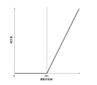
- FIG. 7 is a diagram illustrating an example of the relationship between the operation state value and the correction amount.
- the storage device 10c stores data (for example, a map or an arithmetic expression) in which the relationship shown in FIG. 7 is digitized.
- the correction value is set to 0, and the correction for bringing the reference target engine speed close to the best fuel economy engine speed is as follows. Limited.
- the driving state value exceeds the threshold value Dth, the correction value gradually increases according to the driving state value.
- the correction amount is proportional to the operating state value.
- the relationship between the driving state value and the correction amount may be changed as appropriate.
- the correction amount and the driving state value may be represented by an arbitrary curve so that the correction amount increases in accordance with the driving state value. Further, the correction amount may be increased stepwise according to the operating state value. An upper limit may be set for the correction amount itself.
- Rotational speed correction unit 11B calculates an operating state value as follows, for example.
- the rotation speed correction unit 11B calculates the first load state value based on the accelerator operation amount and the vehicle speed. Further, the rotation speed correction unit 11B calculates the second load state value based on the change speed of the accelerator operation amount. Further, the rotation speed correction unit 11B calculates the third load state value based on the vehicle speed and the acceleration of the vehicle.
- the rotation speed correction unit 11B calculates an operation state value by using all or part of these load state values.
- Each load state value is a value that comprehensively evaluates the load applied to the engine 4 and the possibility that it will change, and indicates the degree of stability of the operation state in the same manner as the operation state value.
- the greater the load state value the more stable the driving state of the vehicle and the less likely it is to change due to an acceleration instruction or the like.
- the smaller the load state value the higher the possibility that the driving state of the vehicle will change, and it is expected that acceleration or deceleration will occur frequently.
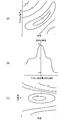
- FIG. 8A is an example of a map that associates the accelerator operation amount, the vehicle speed, and the first load state value.
- the solid line indicates the contour line of the first load state value.
- the first load state value is set high in a driving region where the driving state is estimated to be stable (for example, a region where both the vehicle speed and the accelerator operation amount are medium).
- the rotation speed correction unit 11B refers to this map, for example, and calculates the first load state value from the accelerator operation amount and the vehicle speed detected based on the output of the sensor.
- FIG. 8B is an example of a map that associates the change speed of the accelerator operation amount with the second load state value. Also in this map, the second load state value is set high in the driving region where the driving state is estimated to be stable, that is, in the driving region where the change speed of the accelerator operation amount is small.
- the rotation speed correction unit 11B calculates the change speed of the accelerator operation amount, and then calculates a second load state value corresponding to the calculated change speed of the accelerator operation amount with reference to this map.
- FIG. 8C is an example of a map that associates the vehicle speed, the vehicle acceleration, and the third load state value.
- the solid line shows the contour line of the third load state value L3.
- the third load state value is set high in the driving region in which the driving state is estimated to be stable, specifically, in the driving region where the vehicle speed is medium and the acceleration is low.
- the rotational speed correction unit 11B refers to this map and calculates a third load state value corresponding to the vehicle speed detected based on the output of the sensor and the acceleration calculated from the vehicle speed.
- the rotation speed correction unit 11B selects a load state value used for calculation of the operation state value. For example, when the signs of all the load state values described above match, the rotation speed correction unit 11B calculates the operation state value using all the load state values. On the other hand, when the signs of all the load state values do not match, the rotation speed correction unit 11B does not use any load state value and does not calculate the operation state value in the current process. That is, the rotation speed correction unit 11B does not update the operating state value obtained in the previous process.
- the rotation speed correction unit 11B selects two or three of the first load state value, the second load state value, and the third load state value that have the same sign, and uses the selected load state value.
- An operating state value may be calculated.
- the rotation speed correction unit 11B calculates an operation state value based on the selected load state value. Specifically, the rotation speed correction unit 11B calculates an operation state value based on the selected load state value and the operation state value obtained in the previous process. For example, the rotation speed correction unit 11B calculates a product of the selected load state values, adds the product to the operation state value obtained in the previous process, and sets the result of the addition as a new operation state value. Further, the rotation speed correction unit 11B may calculate the sum of the selected load state values, add the sum to the operation state value obtained in the previous process, and use the result of the addition as a new operation state value.
- the rotation speed correction unit 11B calculates an average value or median value of the selected load state values, adds the average value or median value to the operation state value obtained in the previous process, and newly adds the result of the addition. It is good also as a driving
- the rotation speed correction unit 11B may calculate the driving state value set in advance without updating the driving state value. Good.
- the rotation speed correction unit 11B calculates a correction amount for the reference target engine rotation speed based on the operation state value calculated in this way. For example, the rotation speed correction unit 11B calculates the correction amount from the driving state value using the above-described map and arithmetic expression illustrated in FIG. Then, the rotation speed correction unit 11B subtracts the correction amount from the reference target engine rotation speed, and sets the result as the final target engine rotation speed. In addition, in order to suppress a rapid variation in the correction amount, the calculation may be performed based not only on the operation state value but also on the correction amount obtained in the past process. For example, the rotation speed correction unit 11B may use an average value of correction amounts calculated within a predetermined period as the correction amount obtained in the current process. The rotation speed correction unit 11B may perform a filter process on the correction amount and use the result as the correction amount obtained in the current process.
- the rotation speed correction unit 11B subtracts the correction amount from the reference target engine rotation speed, and when the obtained value is lower than the best fuel consumption engine rotation speed (that is, N3 in FIG. 3), the best fuel consumption engine.
- the speed is set as the final target engine speed. Further, when the value obtained by subtracting the correction amount from the reference target engine speed is smaller than the lower limit value of the engine speed determined by the current vehicle speed, the rotation speed correction unit 11B sets the lower limit value as the final target engine speed.
- the lower limit value of the engine speed is a value determined by the vehicle speed and the minimum speed ratio (speed ratio when CVT5 is set to HIGH).
- the rotation speed correction unit 11B when the reference target engine speed is lower than the best fuel efficiency engine speed, for example, when the reference target engine speed is lower than the engine speed N3 shown in FIG. 3, the rotation speed correction unit 11B has been described so far.
- the reference target engine speed may be set as the final target engine speed without executing the correction.
- the correction by the rotation speed correction unit 11B is not limited to that described above.
- the rotation speed correction unit 11B may multiply a predetermined value by an operation state value and use the result as a correction amount.
- an input device for the rider to input the degree of fuel efficiency is installed in the vehicle, and the best fuel economy engine speed and the reference target engine speed are proposed based on information (value) obtained from the input device. And the result may be used as the final target engine speed.
- the target gear ratio calculation unit 13 calculates the target gear ratio so that the actual engine speed becomes the final target engine speed. That is, the target speed ratio calculation unit 13 calculates the target speed ratio based on the final target engine speed and the speed of the mechanism downstream of the CVT 5.
- the target gear ratio calculation unit 13 in this example calculates the target gear ratio based on the final target engine speed and the vehicle speed detected by the vehicle speed sensor 27. For example, the target speed ratio calculation unit 13 calculates the target speed ratio based on a value obtained by dividing the final target engine speed by the vehicle speed and the speed reduction ratio of the final speed reduction mechanism 7.
- the target gear ratio calculation unit 13 sets the upper limit or the lower limit as the target gear ratio.
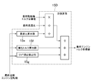
- the control device 10 includes an angle conversion unit 14, a driving force target calculation unit 15, and a target throttle opening calculation unit 18 as functions thereof.
- the driving force target calculation unit 15 includes a reference engine torque target calculation unit 15A, a conversion unit 15B, a driving force target correction unit 15C, and an inverse conversion unit 15D.
- the control device 10 repeatedly executes a series of processes executed by these functional units 14, 15A, 15B, 15C, and 18 at a preset cycle.
- the storage device 10c stores a map and a relational expression for converting the accelerator operation amount into the throttle opening.
- the throttle opening degree defined by the map or the relational expression has a one-to-one correspondence with the accelerator operation amount.
- the throttle opening is proportional to the accelerator operation amount.
- the angle conversion unit 14 refers to the relational expression and the map, converts the accelerator operation amount detected by the accelerator sensor 24 into the throttle opening, and sets the throttle opening obtained as a result as the reference throttle opening.
- the driving force target calculation unit 15 calculates a target value related to the driving force of the vehicle based on the reference target engine speed.
- the target value related to the driving force of the vehicle is a target value related to engine torque (hereinafter referred to as engine torque target value) and a target value related to torque of the driving wheel (rear wheel 8) (driving wheel torque target value).
- the engine torque target value is a target engine torque or a target engine output.
- the drive wheel torque target value is specifically the target rear wheel torque or the work rate of the rear wheel 8 (rear wheel torque ⁇ rotational speed of the rear wheel 8).
- the target throttle opening calculation unit 18 calculates the target throttle opening based on these target values.
- the target engine torque is the engine torque target value and the target rear wheel torque is the drive wheel torque target value will be described.
- the reference engine torque target calculation unit 15A calculates an engine torque target value based on the reference target engine speed (hereinafter, this target value is referred to as a reference engine torque target value).
- the reference engine torque target calculation unit 15A calculates the reference engine torque target value by, for example, the following process.
- the first output characteristic information defined by the output characteristics of the engine 4 is stored in advance in the storage device 10c.
- the first output characteristic information is, for example, information representing the relationship among the throttle opening, the engine speed, and the engine torque.
- the storage device 10c stores a map that correlates the throttle opening, the engine speed, and the engine torque (hereinafter, this map is referred to as a first engine torque map).
- the reference engine torque target calculation unit 15A refers to the first engine torque map, calculates the engine torque corresponding to the reference throttle opening obtained by the angle conversion unit 14 and the reference target engine speed, and calculates the engine torque.
- the reference engine torque target value is used.
- the first output characteristic information may be a map or a relational expression that correlates the throttle opening, the engine speed, and the engine output. Further, the storage device 10c may store a relational expression or a map representing a relationship among the accelerator operation amount, the engine speed, and the engine torque as the first output characteristic information.
- the reference engine torque target calculation unit 15A refers to the first output characteristic information, calculates the engine torque corresponding to the accelerator operation amount detected by the accelerator sensor 24 and the reference target engine speed, and the engine torque Is the reference engine torque target value.
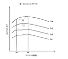
- FIG. 9 is a diagram showing an example of the first engine torque map.
- the horizontal axis represents the engine speed
- the vertical axis represents the engine torque.
- a torque curve showing the relationship between the engine speed and the engine torque is illustrated for the throttle openings Th1 to Th4.
- the reference engine torque target calculation unit 15A refers to such a first engine torque map, and calculates a reference engine torque target value corresponding to the reference throttle opening and the reference target engine speed.
- the accelerator operation amount, the engine speed, and the engine torque set in the first engine torque map of this example are values based on the actual output characteristics of the engine 4.
- the throttle opening, engine speed, and engine torque set in the first engine torque map may partially deviate from the actual output characteristics of the engine 4.
- the throttle opening, the engine speed, and the engine torque set in the first engine torque map may be set to values preferable for the riding feeling or acceleration performance of the motorcycle 1. This form will be described later.
- the conversion unit 15B converts the reference engine torque target value to the above-described drive wheel torque target value that is a target value related to the rear wheel torque based on the reference target engine speed (hereinafter, the drive wheel calculated by the conversion unit 15B).
- the torque target value is used as the reference drive wheel torque target value).
- the conversion unit 15B in this example converts the target engine torque into the target rear wheel torque.
- the torque transmitted from the engine 4 to the rear wheel 8 includes, in addition to the torque output from the engine 4, inertia torque of the engine 4 generated by a change in engine speed.
- the torque output by the engine 4 is transmitted to the rear wheel 8 after being reduced by the friction between the belt and pulley of the CVT 5 and the torque required for bending the belt.
- the conversion unit 15B calculates the reference drive wheel torque target value from the reference engine torque target value in consideration of such torque addition and loss.
- FIG. 10 is a block diagram showing functions of the conversion unit 15B.
- the conversion unit 15B includes an inertia torque calculation unit 15a, a CVT loss calculation unit 15b, and a gear ratio calculation unit 15c as functions thereof.
- the inertia torque calculator 15a calculates the inertia torque of the engine 4 generated by the change in the engine speed.
- the inertia torque calculator 15a of this example calculates the inertia torque based on the reference target engine speed.
- the inertia torque calculation unit 15a calculates the inertia torque based on the change speed of the reference target engine speed and the inertia moment of the mechanism (crankshaft or piston of the engine 4) upstream of the CVT 5.
- Inertia torque Inertia moment ⁇ Change speed of reference target engine speed).
- the inertia torque calculation method is not limited to this.
- the inertia torque calculator 15a may calculate the inertia torque based on the speed of change of the gear ratio.
- the inertia torque calculation unit 15a calculates the gear ratio based on the reference target engine speed and the vehicle speed, for example, and the change speed of the gear ratio, the acceleration of the vehicle, and the above-described The inertia torque is calculated based on the inertia moment.
- the CVT loss calculation unit 15b calculates a torque lost in the CVT 5 (this torque is referred to as CVT loss).
- the CVT loss calculation unit 15b is based on, for example, the reference target engine speed, the output shaft speed detected by the output shaft speed sensor 26, and the torque transmitted through the CVT 5 (torque output from the engine 4). To calculate the CVT loss.
- the transmission ratio calculation unit 15c calculates the transmission ratio of the CVT 5.
- the speed ratio calculation unit 15c in this example calculates the speed ratio of the CVT 5 based on the reference target engine speed.
- conversion unit 15B uses this upper limit or lower limit in the processing described later.
- the conversion unit 15B of this example first subtracts the inertia torque calculated by the inertia torque calculation unit 15a and the CVT loss calculated by the CVT loss calculation unit 15b from the reference engine torque target value (The value obtained by this subtraction is called the actual transmission torque). Thereafter, the conversion unit 15B multiplies the actual transmission torque by the speed ratio obtained by the speed ratio calculation unit 15c and the final reduction ratio, and sets the value obtained by the multiplication as a reference driving wheel torque target value.
- the reference drive wheel torque target value may be the target output of the rear wheel 8.
- the conversion unit 15B may calculate the reference drive wheel torque target value from the reference engine torque target value by performing the following processing, for example. That is, the conversion unit 15B subtracts the inertia torque from the reference engine torque target value. Then, conversion unit 15B multiplies the value obtained by the subtraction by the reference target engine speed. Thereafter, conversion unit 15B subtracts the CVT loss (the power lost in CVT5) from the value obtained by the multiplication. Then, conversion unit 15B multiplies the value obtained by subtraction of CVT loss by the speed ratio obtained by speed ratio calculation unit 15c and the final reduction ratio, and sets the result as the reference drive wheel torque target value.
- the control device 10 includes the driving force target correction unit 15C.
- the driving force target correction unit 15C corrects the reference driving wheel torque target value, and calculates the value obtained by the correction as the final driving wheel torque target value.
- the driving force target correction unit 15C calculates a final driving wheel torque target value from the reference driving wheel torque target value using a filter function.
- the filter function of this example is defined such that the rising speed of the final driving wheel torque target value is smaller than the rising speed of the reference driving wheel torque target value.
- the filter function is defined so that the rising speed of the final driving wheel torque target value is smaller than the rising speed of the reference driving wheel torque target value. According to this filter function, the vehicle can be smoothly accelerated.
- the transfer function G (s) of the filter function of this example includes a first-order lag element G1 (s) represented by the following equation.
- G1 (s) 1 / (T ⁇ s + 1)
- T is a time constant and s is an operator.
- the final driving wheel torque target value is higher than the reference driving wheel torque target value (Tp1 in FIG. 4) (FIG. 4). To Tp2) and then decreases toward the reference driving wheel torque target value.
- the filter function is defined such that the final drive wheel torque target value changes in this way with respect to the reference drive wheel torque target value. According to such a filter function, it is possible to maintain a feeling of acceleration.
- the transfer function G (s) of the filter function of this example includes a first-order lag element G2 (s) represented by the following equation.
- G2 (s) (P ⁇ L ⁇ s + 1) / (L ⁇ s + 1)
- P is a proportional gain set to a value larger than 1
- L is a time constant.
- G2 (s) can be modified as follows.
- G2 (s) P ⁇ (P ⁇ 1) / (Ls + 1)
- the term P is a proportional element of the transfer function G (s). Therefore, the transfer function G (s) of the filter function is expressed by the following equation.
- G (s) G1 (s) ⁇ G2 (s)
- FIG. 11 is a block diagram for explaining an example of changes in the reference driving wheel torque target value and the final driving wheel torque target value by the transfer function G (s).
- the step response of the transfer function G (s) is shown as an example. That is, in the figure, the input (reference driving wheel torque target value) is a step function.
- a waveform Y2 is an output waveform by the above-described element G2 (s).
- a waveform Y1 is a waveform of the final drive wheel torque target value.
- the waveform Y2 when the reference drive wheel torque target value rises to T1 at time t0, the output of the element G2 (s) rises to T1 ⁇ P at time t0. After time t0, the output of the element G2 (s) gradually decreases toward the reference drive wheel torque target value T1.
- the final drive wheel torque target value gradually rises after the time t0 as compared with the output of the element G2 (s). That is, the rising speed of the final driving wheel torque target value is smaller than the rising speed of the reference driving wheel torque target value.
- the final drive wheel torque target value reaches a peak value (T1 ⁇ P) higher than the reference drive wheel torque target value with a delay of tg1 from the time t0. Thereafter, the reference drive wheel torque target value gradually decreases toward the reference drive wheel torque target value T1.
- the time tg2 until the value indicated by the output waveform Y2 of the element G2 (s) matches the reference drive wheel torque target value T1 can be controlled by the time constant L of the transfer function G (s). That is, by adjusting the time constant L, it is possible to adjust the time for which the feeling of acceleration lasts.
- the ratio of the final driving wheel torque target value to the peak of the reference driving wheel torque target value can be controlled by the proportional gain P of the transfer function G (s). Therefore, the acceleration performance can be adjusted by adjusting the proportional gain P.
- the delay time tg1 required for the final drive wheel torque target value to reach the peak value (T1 ⁇ P) can be controlled by the time constant T of the element G1 (s).
- the filter function is set based on the transfer function G (s) that realizes such a waveform. That is, the filter function is a function including the above-described P, T, and L as coefficients.
- T, L, and P may be changed based on the driving state of the vehicle.
- the time constant T may be changed to a value smaller than the reference value at the time of shifting.
- the time constant T may be set based on the difference between the final target engine speed and the current engine speed so that the time constant T becomes smaller during gear shifting.
- the proportional gain P may be set based on the accelerator operation amount or the reference engine torque target value so that the gain P increases during acceleration.
- the driving force target correction unit 15C in this example includes a correction condition determination unit 15d.
- the correction condition determination unit 15d determines whether or not the acceleration request from the user satisfies a condition (hereinafter referred to as correction condition) for performing the correction (calculation using the above-described filter function) of the driving force target correction unit 15C.
- the correction condition determination unit 15d determines whether or not the acceleration request is higher than a preset degree based on the accelerator operation amount detected by the accelerator sensor 24.
- the correction condition determination unit 15d determines whether or not the accelerator operation amount is higher than a predetermined threshold (hereinafter referred to as a first operation amount threshold).
- the correction condition determination unit 15d determines whether or not the change speed of the accelerator operation amount is higher than a predetermined threshold (hereinafter referred to as a change speed threshold). The correction condition determination unit 15d determines that the acceleration request satisfies the correction condition when the accelerator operation amount is higher than the first operation amount threshold and the change speed of the accelerator operation amount is higher than the change speed threshold.
- a predetermined threshold hereinafter referred to as a change speed threshold
- the correction condition determination unit 15d determines that the acceleration request no longer satisfies the correction condition when the acceleration request is lower than a preset degree. For example, the correction condition determination unit 15d determines whether or not the accelerator operation amount is lower than a predetermined threshold (hereinafter referred to as a second operation amount threshold). Then, the correction condition determination unit 15d determines that the acceleration request does not satisfy the acceleration correction condition when the accelerator operation amount becomes lower than the second operation amount threshold.
- a predetermined threshold hereinafter referred to as a second operation amount threshold
- the driving force target correction unit 15C uses the filter function described above to make the final driving wheel. Calculate the torque target value.
- the driving force target correction unit 15C calculates the reference driving wheel torque target value as the final driving wheel torque target value without using the filter function when the comfortable driving mode is not selected. Further, the driving force target correction unit 15C calculates the reference driving wheel torque target value as the final driving wheel torque target value without using the filter function even when the driver's acceleration request does not satisfy the correction condition. .
- the reference driving wheel torque target value changes as shown in FIG. 4 described above, for example. That is, time t1 in FIG. 4 is a timing when the accelerator operation amount increases and the correction condition is satisfied. Also, time t3 in the figure is the timing when the accelerator operation amount is reduced and the correction condition is not satisfied. Before the time t1 and after the time t3, the correction using the filter function is not performed, so that the reference driving wheel torque target value and the final driving wheel torque target value match. Between the time t1 and the time t3, the final driving wheel torque target value rises more slowly than the reference driving wheel torque target value, and gradually approaches the reference driving wheel torque target value after reaching the peak value Tp2. . Further, the peak value Tp2 of the final drive wheel torque target value is higher by a ratio corresponding to the proportional gain P than the peak value Tp1 of the reference drive wheel torque target value.
- the time when the filter function is used is not limited to that described above.
- the calculation using the filter function may be executed in the normal mode and the fuel consumption mode.
- the time constants T and L and the proportional gain P may be set according to the mode.
- correction using a filter function may be performed even during deceleration.
- the proportional gain P may be smaller than 1.
- the proportional gain P may be smaller than 1 when low-speed driving continues, such as when driving in an urban area.
- the target throttle opening calculation unit 18 calculates the target throttle opening based on the final drive wheel torque target value.
- the driving force target calculation unit 15 in this example includes the inverse conversion unit 15D.
- the inverse conversion unit 15D converts the final driving wheel torque target value into an engine torque target value (final engine torque target value) used by the target throttle opening calculation unit 18.
- the final engine torque target value is the target engine torque.
- the target throttle opening calculation unit 18 calculates the target throttle opening based on the final engine torque target value.
- the inverse conversion unit 15D converts the final drive wheel torque target value into the final engine torque target value based on the final target engine speed.
- FIG. 12 is a block diagram showing the function of the inverse conversion unit 15D. As shown in the figure, the inverse conversion unit 15D includes an inertia torque calculation unit 15f and a CVT loss calculation unit 15g, similarly to the conversion unit 15B.
- the inverse conversion unit 15D calculates the final engine torque target value from the final drive wheel torque target value by performing the reverse operation of the conversion unit 15. Specifically, the inverse conversion unit 15D first calculates the target value of the upstream torque of the CVT 5 from the final driving wheel torque target value based on the transmission ratio and the final reduction ratio of the CVT 5. For example, the inverse conversion unit 15D divides the final drive wheel torque target value by the transmission ratio of the CVT 5 and the final reduction ratio, and sets the result as the target value of the torque upstream of the CVT 5.
- the speed ratio used in the division by the inverse conversion unit 15D is a speed ratio calculated based on the final target engine speed and the vehicle speed, for example. That is, the gear ratio is a gear ratio that is equal to the gear ratio calculated by the target gear ratio calculation unit 13, for example.
- the inertia torque calculation unit 15f calculates the inertia torque of the engine 4 generated by the change in the engine speed, similarly to the inertia torque calculation unit 15a.
- the method for calculating the inertia torque is not limited to this.
- the inertia torque calculation unit 15f may calculate the inertia torque based on the change speed of the gear ratio, similarly to the inertia torque calculation unit 15a.
- the CVT loss calculation unit 15d for example, the final target engine speed, the output shaft speed detected by the output shaft speed sensor 26, and the torque (engine) transmitted through the CVT 5 4), the CVT loss is calculated.
- the inverse conversion unit 15D is calculated by the target torque value of the mechanism upstream of the CVT 5 obtained by the division described above, the inertia torque calculated by the inertia torque calculation unit 15f, and the CVT loss calculation unit 15g.
- the final engine torque target value is calculated based on the CVT loss. Specifically, the inverse conversion unit 15D uses the inertia torque calculated by the inertia torque calculation unit 15f and the CVT loss calculated by the CVT loss calculation unit 15g as the target torque value of the mechanism upstream of the CVT 5. And the result is used as the final engine torque target value.
- the target throttle opening calculation unit 18 calculates the target throttle opening based on the final engine torque target value and the final target engine speed.
- the processing of the target throttle opening calculation unit 18 is executed as follows, for example.
- the second output characteristic information defined by the output characteristics of the engine 4 is stored in advance in the storage device 10c. Similar to the first output characteristic information, the second output characteristic information is, for example, information representing the relationship between the throttle opening, the engine speed, and the engine torque. In the example described here, a map that associates the throttle opening, the engine speed, and the engine torque with each other is stored in the storage device 10c (hereinafter, this map is referred to as a second engine torque map).
- the target throttle opening calculation unit 18 refers to the second engine torque map, calculates the throttle opening corresponding to the final engine torque target value and the final target engine speed, and sets the throttle opening as the target throttle opening. .
- the final engine torque target value in this example is the final target value for engine torque.
- the second output characteristic information may be a map or a relational expression that associates the throttle opening, the engine speed, and the engine output with each other.
- Each functional unit described above of the control device 10 operates as follows in each of the three control modes.
- the normal mode will be described.
- the correction by the rotation speed correction unit 11B is not executed.
- the reference target engine speed calculated by the reference speed calculator 11A is set as the final target engine speed.
- the reference rotation speed calculation unit 11A calculates the engine rotation speed N1 corresponding to the accelerator operation amount as the reference target engine rotation speed.
- This engine speed N1 is set as the final target engine speed.
- the target gear ratio calculation unit 13 calculates the target gear ratio based on the final target engine speed.
- the correction using the filter function by the driving force target correction unit 15C is not executed in the normal mode.
- the reference engine torque target value calculated by the reference engine torque target calculation unit 15A is the same as the final engine torque target value calculated by the inverse conversion unit 15D.
- the target throttle opening calculated by the target throttle opening calculation unit 18 matches the reference throttle opening calculated by the angle conversion unit 14.
- the throttle opening degree Th1 is set as the target throttle opening degree.
- the reference rotation speed calculation unit 11A calculates the reference target engine rotation speed N1 based on the accelerator operation amount, as in the normal mode.
- the rotation speed correction unit 11B corrects the target engine rotation speed so as to approach the engine rotation speed N3 at the operating point on the best fuel consumption curve A from the reference target engine rotation speed N1, and the rotation speed obtained as a result (in FIG. 3).
- N2) is the final target engine speed.
- the target gear ratio calculation unit 13 calculates the target gear ratio based on the final target engine speed N2.
- the driving force target calculation unit 15 calculates the rear wheel torque (reference driving wheel torque target value) at the operation point P1 of the reference target engine speed N1 by the processing of the reference engine torque target calculation unit 15A and the conversion unit 15B. To do. In the fuel consumption mode, correction of the drive wheel torque target value by the drive force target correction unit 15C is not executed. Therefore, the target throttle opening calculation unit 18 determines the final drive wheel torque target value (more specifically, the final engine torque target value calculated by the inverse conversion unit 15D) equal to the reference drive wheel torque target value, and the final target engine. Based on the rotational speed, the target throttle opening is calculated.
- the target throttle opening calculation unit 18 can obtain the same rear wheel torque as the rear wheel torque at the operation point P1, and the throttle opening at the operation point P2 at which the engine speed becomes the final target engine speed.
- the degree (Th2 in FIG. 3) is set as the target throttle opening.
- the comfortable driving mode will be explained.
- the correction by the rotation speed correction unit 11B is not executed. Therefore, the reference target engine speed N1 calculated by the reference speed calculation unit 11A is set as the final target engine speed.
- the target gear ratio calculation unit 13 calculates the target gear ratio based on the final target engine speed.
- the driving force target calculation unit 15 performs the processing at the reference throttle opening (Th1 in FIG. 3) and the operation point P1 of the reference target engine speed N1 by the processing of the reference engine torque target calculation unit 15A and the conversion unit 15B.
- the wheel torque (reference drive wheel torque target value) is calculated.
- the driving force target correction unit 15C calculates a final driving wheel torque target value from the reference driving wheel torque target value using a filter function.
- the target throttle opening calculation unit 18 calculates the target throttle opening based on the final engine torque target value obtained from the final driving wheel torque target value by the processing of the inverse conversion unit 15D and the final target engine speed. .
- the processing executed by the control device 10 is repeatedly executed at a preset cycle. Therefore, the reference driving wheel torque target value gradually changes with time, and the final driving wheel torque target value also changes accordingly. As shown in FIG. 4, when the driver's acceleration request satisfies the correction condition, the final drive wheel torque target value changes more slowly than the reference drive wheel torque target value.
- the target throttle opening calculation unit 18 opens the target throttle opening based on the final drive wheel torque target value and the final target engine speed obtained at each time point. Calculate the degree. As a result, the target throttle opening changes in accordance with the final drive wheel torque target value.
- the storage device 10c stores the first engine torque map and the second engine torque map as output characteristic information.
- the throttle opening, engine speed, and engine torque set in the first engine torque map are not values stipulated by the actual output characteristics of the engine 4, but values suitable for obtaining a comfortable ride feeling are stored. May be.
- the throttle opening, the engine speed, and the engine torque set in the second engine torque map may be closer to the actual output characteristics of the engine 4 as compared to the first engine torque map.
- FIG. 13 is a diagram showing an example of the first engine torque map having such a configuration.
- the first engine torque map As shown in the figure, for example, in the actual output characteristics of the engine 4 (broken lines L5 and L6), there is a valley of engine torque between the engine speeds N5 and N6.
- the engine torque defined by the first engine torque map deviates from this valley and gradually increases between the engine speeds N5 and N6.
- the throttle opening, engine speed, and engine torque set in the second engine torque map are values defined by the actual output characteristics of the engine 4. That is, the engine torque defined by the second engine torque map has a valley between the engine speeds N5 and N6.
- the reference engine torque target value calculated with reference to the first engine torque map is defined by the actual output characteristics of the engine 4.
- the engine torque is higher than the engine torque.
- the final engine torque target value is calculated based on this high reference engine torque target value.
- the target throttle opening is set so that the final engine torque target value torque can be obtained. Therefore, such a difference between the two engine torque maps can realize an output characteristic having a desirable torque curve rather than a torque curve defined by an actual output characteristic of the engine 4.
- the conversion unit 15B calculates the reference drive wheel torque target value from the reference engine torque target value using the inertia torque calculated by the inertia torque calculation unit 15a. Further, the inverse conversion unit 15D calculates the final engine torque target value from the final drive wheel torque target value by using the inertia torque calculated by the inertia torque calculation unit 15f. However, the conversion unit 15B may calculate the reference drive wheel torque target value from the reference engine torque target value without using the inertia torque. Then, the inverse conversion unit 15D may calculate the final engine torque target value based on the final drive wheel torque target value and the inertia torque, as in the example of FIG.
- FIG. 14 is a block diagram showing processing of the conversion unit 15B according to this embodiment.
- the conversion unit 15B of this embodiment includes a CVT loss calculation unit 15b and a gear ratio calculation unit 15c, but does not include an inertia torque calculation unit 15f. Therefore, the inertia torque is not subtracted when calculating the reference drive wheel torque target value from the reference engine torque target value.
- inertia torque is added in calculating the final engine torque target value.
- FIG. 15 is a time chart for explaining the effect of the embodiment using the inertia torque only in the inverse conversion unit 15D.
- FIG. 5A is a time chart in which both the conversion unit 15B and the reverse conversion unit 15D use inertia torque
- FIG. 5B is a time chart in a form where only the reverse conversion unit 15D uses inertia torque. It is.
- FIGS. 4A and 4B show changes in accelerator operation amount, throttle opening, engine speed, and rear wheel torque.
- the accelerator operation amount increases at time t1.
- the throttle opening increases.
- the throttle opening changes similarly to the accelerator operation amount.
- the engine speed starts increasing at time t1 due to an increase in the throttle opening.
- the rear wheel torque starts increasing at time t1 due to an increase in the throttle opening.
- the increase of the rear wheel torque is hindered in the period T.
- the accelerator operation amount increases at time t1, and the throttle opening increases accordingly, as in FIG.
- the engine speed starts increasing at time t1 due to an increase in the throttle opening.
- the target throttle opening is set so as to compensate for the torque (inertia torque) consumed for increasing the engine speed. Therefore, as shown in FIG. 2B, the throttle opening greatly increases as compared with the accelerator operation amount during the period when the engine speed is increasing. As a result, the increase in the rear wheel torque is not hindered even during a period in which the engine speed is increasing. As a result, the acceleration performance of the vehicle is improved.
- the control device 10 may correct the driving force target value based on the traveling load acting on the vehicle when the vehicle is traveling.
- FIG. 16 is a block diagram showing functions of the control device 10 according to this embodiment.
- the driving force target calculation unit 15 includes a travel load correction unit 15E.
- the traveling load correction unit 15E corrects the driving force target value based on the traveling load acting on the vehicle.
- the traveling load correction unit 15E further corrects the final driving force target value calculated by the driving force target correction unit 15C, and the inverse conversion unit 15D sets the final driving force target value corrected by the traveling load correction unit 15E. Based on this, a final engine torque target value is calculated.
- the travel load is a load applied to the vehicle due to, for example, a rider, an object placed on the vehicle, or a gradient of a road on which the vehicle travels.
- the travel load correction unit 15E estimates the travel load acting on the vehicle, for example, by the following process.
- the storage device 10c stores information (hereinafter referred to as first reference acceleration information) indicating the relationship between the driving force target value (for example, rear wheel torque) and the acceleration of the vehicle in a state where the reference traveling load is applied to the vehicle. ) Is stored in advance.
- the reference traveling load is, for example, a load applied to a vehicle when a rider with a standard weight is riding on the vehicle and the vehicle is traveling on a flat road.
- the first reference acceleration information is information indicating the relationship between the driving force target value and the acceleration of the vehicle when a rider with a standard weight is on the vehicle and the vehicle is traveling on a flat road. It is.
- the first reference acceleration information is, for example, a map or a relational expression for associating the driving force target value with the vehicle acceleration.
- the traveling load correction unit 15E calculates the actual acceleration of the vehicle based on the output of the vehicle speed sensor 27 when the vehicle is traveling. Further, the travel load correction unit 15E refers to the first reference acceleration information, and calculates an acceleration corresponding to the final driving force target value calculated by the driving force target correction unit 15C (hereinafter, the acceleration calculated in this process is referred to as the first acceleration). 1 reference acceleration).
- the traveling load correction unit 15E calculates the difference between the actual acceleration and the first reference acceleration (hereinafter referred to as the first acceleration difference) as a difference between the traveling load acting during standard traveling and the traveling load acting during the current traveling. To do.
- the traveling load correction unit 15E corrects the final driving force target value calculated by the driving force target correction unit 15C based on the first acceleration difference. For example, the traveling load correction unit 15E adds or subtracts a correction amount corresponding to the first acceleration difference to the final driving force target value calculated by the driving force target correction unit 15C. The traveling load correction unit 15E may multiply the final driving force target value calculated by the driving force target correction unit 15C by a coefficient corresponding to the first acceleration difference. In the form in which such processing is performed, the storage device 10c stores in advance a map or relational expression that associates the first acceleration difference and the correction amount, or a map or relational expression that associates the first acceleration difference and the coefficient.
- the traveling load correction unit 15E stores in advance a map or relational expression that associates the first acceleration difference and the correction amount, or a map or relational expression that associates the first acceleration difference and the coefficient.
- the target engine speed calculation unit 11 includes a traveling load correction unit 11C.
- the traveling load correction unit 11C corrects the target engine speed based on the traveling load acting on the vehicle.
- the traveling load correction unit 11C corrects the reference engine speed calculated by the reference speed calculation unit 11A.
- the rotation speed correction unit 11B described above calculates the final engine rotation speed based on the reference engine rotation speed corrected by the traveling load correction unit 11C.
- the reference engine torque target calculation unit 15A and the inverse conversion unit 15B execute the above-described processing based on the reference engine speed before being corrected by the traveling load correction unit 11C.
- the traveling load correcting unit 11C estimates the traveling load in the same manner as the traveling load correcting unit 15E described above, for example. That is, the storage device 10c stores in advance information indicating the relationship between the target engine speed and the acceleration of the vehicle when a reference load is applied to the vehicle (hereinafter referred to as second reference acceleration information). .
- the reference load is the same as described above, and the second reference acceleration information includes the engine speed and vehicle when a rider with a standard weight is riding on the vehicle and the vehicle is traveling on a flat road. It defines the relationship with the acceleration.
- the second reference acceleration information is, for example, a map or relational expression that associates the engine speed with the vehicle acceleration.
- the traveling load correction unit 11C calculates the actual acceleration of the vehicle based on the output of the vehicle speed sensor 27 when the vehicle is traveling.
- the calculation of the actual acceleration may be executed only in one of the traveling load correction unit 11C and the above-described traveling load correction unit 15E, and the actual acceleration obtained on the other hand may be used on the other side.
- the traveling load correction unit 11C refers to the second reference acceleration information, and calculates an acceleration corresponding to the reference target engine rotation number calculated by the reference rotation number calculation unit 11A (hereinafter, the acceleration calculated in this process is referred to as a second reference acceleration value). Acceleration).
- the traveling load correction unit 11C calculates the difference between the actual acceleration and the second reference acceleration (hereinafter, the second acceleration difference) as the traveling load acting on the vehicle.
- the traveling load correction unit 11C corrects the reference target engine speed calculated by the reference speed calculation unit 11A based on the second acceleration difference. For example, the traveling load correction unit 11C adds or subtracts a correction amount corresponding to the second acceleration difference to the reference target engine rotation number calculated by the reference rotation number calculation unit 11A. Further, the traveling load correction unit 11C may multiply the reference target engine speed calculated by the reference speed calculation unit 11A by a coefficient corresponding to the second acceleration difference. In the form in which such processing is performed, the storage device 10c stores in advance a map or relational expression that associates the second acceleration difference and the correction amount, or a map or relational expression that associates the second acceleration difference and the coefficient.
- the target engine speed calculation unit 11 and the driving force target value calculation unit 15A include the rotation speed correction unit 11C and the travel load correction unit 15E, respectively, so that the correction amount and the correction method based on the travel load acting on the vehicle.
- the degree of freedom can be increased.
- control device 10 described above includes a reference engine torque target calculation unit 15A and a conversion unit 15B. That is, the control device 10 calculates the reference engine torque target value using the first engine torque map, and then converts the reference engine torque target value using the reference target engine speed. However, the control device 10 may directly calculate the reference driving force target value based on the accelerator operation amount and the vehicle speed.
- FIG. 17 is a block diagram illustrating functions of the control device 10 according to this embodiment.
- the control device 10 in this figure includes a reference driving force target calculation unit 15F instead of the reference engine torque target calculation unit 15A and the conversion unit 15B.
- the storage device 10c stores a map and a relational expression for associating the accelerator operation amount, the vehicle speed, and the driving force target value (for example, the target value for the rear wheel torque).
- the reference driving force target calculation unit 15F calculates a driving force target value corresponding to the accelerator operation amount detected by the sensor and the vehicle speed as a reference driving force target value using these maps and relational expressions.
- the target engine speed calculation unit 11 calculates the target engine speed
- the target speed ratio calculation unit 13 calculates the target speed ratio based on the target engine speed.
- the driving force target calculation unit 15 also has a driving force target value (an engine torque target value and a driving wheel torque target) that is a target value related to the driving force of the vehicle based on the accelerator operation amount detected by the sensor and the target engine speed. Value), and the target throttle opening calculation unit 18 calculates the target throttle opening based on the target engine speed and the driving force target value so as to obtain the driving force corresponding to the driving force target value. Yes. According to this, since the target engine speed is calculated first and then the driving force target value is calculated, it becomes easy to set the engine speed to a speed that can realize a comfortable riding feeling.
- the target engine speed calculation unit 11 calculates an engine speed higher than the engine speed at which the fuel efficiency becomes the best as the target engine speed. According to this, the acceleration responsiveness of the vehicle can be improved.
- the driving force target calculation unit 15 calculates a reference driving force target value based on the target engine speed, corrects the reference driving force target value, and calculates a value obtained by the correction as a final driving force target value. Yes.
- the target throttle opening calculation unit 18 calculates the target throttle opening based on the final driving force target value. According to this, it becomes possible to correct the driving force target value as necessary, and the acceleration of the vehicle can be improved.
- the driving force target calculation unit 15 calculates a final driving force target value from the reference driving force target value using a filter function. According to this, the relative change of the final driving force target value with respect to the reference driving force target value can be made desirable.
- the filter function is specified so that the final drive force target value rise speed is smaller than the reference drive force target value rise speed. According to this, smooth acceleration and / or deceleration can be realized.
- the filter function is defined so that when the reference driving force target value increases, the final driving force target value increases to a value higher than the reference driving force target value and then decreases toward the reference driving force target value. According to this, acceleration performance can be improved and acceleration feeling can be maintained.
- the transfer function of the filter function includes a first order lag element. According to this, according to this, smooth acceleration and / or deceleration can be realized.
- the transfer function of the filter function includes a proportional element. According to this, acceleration performance can be improved.
- the driving force target calculation unit 15 calculates an engine torque target value based on the target engine speed, and calculates a driving wheel torque target value based on the engine torque target value and an inertia torque generated by a change in the engine speed. ing.
- the target throttle opening calculation unit 18 calculates the target throttle opening based on the drive wheel torque target value. According to this, it becomes possible to set the target throttle opening that compensates for the loss of driving force due to the generation of inertia torque.
- the target engine speed calculator 11 calculates the engine speed corresponding to the accelerator operation amount detected by the accelerator sensor 24 as a reference target engine speed, and the speed corrector 11B corrects the reference target engine speed, The speed obtained by the correction is calculated as the final target engine speed, and the target speed ratio calculation unit 13 calculates the target speed ratio so that the actual engine speed becomes the final target engine speed.
- the driving force target calculation unit 15 calculates a driving force target value (an engine torque target value and a rear wheel torque target value), which is a target value related to the driving force of the vehicle, based on the reference target engine speed,
- the opening calculation unit 18 calculates the target throttle opening based on the driving force target value based on the reference target engine speed.
- the driving force target value and the target throttle opening are calculated based on the reference target engine speed according to the accelerator operation amount. Therefore, it becomes easy to set the engine speed to the speed that realizes a comfortable ride feeling suitable for the driver's accelerator operation.
- the driving force target value is calculated based on the reference target engine speed
- the target throttle opening is calculated based on the final target engine speed and the driving force target value based on the reference target engine speed. Therefore, even when the final target engine speed is a value obtained by correcting the reference target engine speed, the target throttle opening degree can be set so that the driving force of the vehicle is maintained.
- the driving force target calculation unit 15 refers to the first engine torque map, which is output characteristic information, and determines the driving force target value based on the reference throttle opening and the reference target engine speed converted from the detected accelerator operation value. Calculated.
- the target throttle opening calculation unit 18 refers to the second engine torque map that is output characteristic information, and calculates the target throttle opening based on the driving force target value and the final target engine speed. According to this, it becomes easy to calculate an appropriate target throttle opening.
- the storage device 10c stores a first engine torque map and a second engine torque map different from the first engine torque map as output characteristic information.
- the relationship among the throttle opening, the engine speed, and the engine torque defined in the second engine torque map is closer to the actual output characteristics of the engine than the first engine torque map. According to this, the output characteristic more desirable than the actual output characteristic of the engine 4 can be realized by utilizing the difference between the first engine torque map and the second engine torque map.
- the target throttle opening calculation unit 18 calculates the target throttle opening based on the driving force target value and the inertia torque of the engine 4 due to the change in the engine speed. According to this, it is possible to set the target throttle opening that compensates for the driving force loss due to the generation of inertia torque.
- the driving force target calculation unit 15 calculates, as driving force target values, an engine torque target value that is a target value related to engine torque and a driving wheel torque target value that is a target value related to the torque of the rear wheels 8.
- the driving force target correction unit 15C corrects the reference driving wheel torque target value and calculates the target value obtained by the correction as the final driving wheel torque target value.
- the target throttle opening calculation unit 18 calculates the target throttle opening based on the final engine torque target value based on the final driving wheel torque target value. According to this, compared with the case where the target value for the engine torque is corrected, it is possible to perform a correction desirable for the ride feeling.
- the conversion unit 15B calculates the reference drive wheel torque target value from the reference engine torque target value without using the inertia torque, and the inverse conversion unit 15D calculates the final drive wheel torque target value.
- the final engine torque target value is calculated based on the inertia torque. According to this, it becomes possible to set the target throttle opening that compensates for the loss of driving force due to the generation of inertia torque.
- the present invention is not limited to the control by the control device 10 described above, and various changes can be made.
- a map in which the throttle opening, the engine speed, and the engine output are associated may be used as the output characteristic information.
- the CVT loss does not necessarily have to be used.
- the reference drive wheel torque target value is calculated from the reference engine torque target value, and the reference drive wheel torque target value is calculated.
- the reference engine torque target value may be corrected, and the value obtained by the correction may be used as the final engine torque target value.
- the target engine speed obtained by correcting the reference target engine speed is referred to as the final target engine speed.
- the term “final” does not necessarily exclude that the target engine speed obtained by correcting the reference target engine speed is further corrected.
- FIG. 18 is a block diagram showing a modification of the processing executed by the driving force target value calculation unit 15.
- the driving force target value calculation unit 15 in this example includes a reference travel resistance calculation unit 15Ga, a travel load estimation unit 15Gb, and a travel load correction amount calculation unit 15Gc.
- the driving force target value calculation unit 15 includes a driving force target correction unit 15H.
- the reference running resistance calculation unit 15Ga calculates a reference running resistance that is a running resistance received when the vehicle is running at a constant vehicle speed.
- the reference running resistance is mainly caused by the air resistance that the vehicle receives during running, and changes according to the vehicle speed. Therefore, the reference running resistance calculation unit 15Ga calculates the reference running resistance based on the vehicle speed detected by the vehicle speed sensor 27.
- basic information relating the reference running resistance and the vehicle speed is stored in advance in the storage device 10c (the basic information is a map, for example, and hereinafter referred to as a running resistance map).
- FIG. 19 is a diagram showing an example of the relationship between the reference running resistance and the vehicle speed.
- the horizontal axis is the vehicle speed
- the vertical axis is the reference running resistance.
- the reference running resistance generally increases as the vehicle speed increases.
- the reference running resistance calculation unit 15Ga calculates a reference running resistance corresponding to the vehicle speed detected by the vehicle speed sensor 27 using a map or a relational expression that defines such a relationship between the reference running resistance and the vehicle speed.
- the reference running resistance is used for correcting the drive wheel torque target value, as will be described in detail later. Therefore, the reference running resistance is a value of the same dimension as the drive wheel torque target value. That is, when the driving wheel torque target value is a target value for the rear wheel torque, the reference running resistance is a dimension of torque. If the drive wheel torque target value is a target value for the output (power) of the rear wheel 8, the reference running resistance is the dimension of the output.
- the traveling load estimation unit 15Gb estimates a traveling load exceeding such a reference traveling load.
- the process of the traveling load estimation unit 15Gb is executed as follows, for example.
- the vehicle acceleration is set to a
- the vehicle weight is set to M
- the engine torque is set to Teg
- the inertia torque of the engine 4 is set to Ti
- the CVT loss described above is set to Tloss.
- these have the following relationship.
- (Teg ⁇ Ti) ⁇ speed ratio ⁇ Tloss (M ⁇ a + Lv) ⁇ k
- the engine torque Teg can be calculated based on the engine speed and the throttle opening with reference to an engine torque map (for example, the engine torque map shown in FIG. 9).
- the inertia torque Ti is a value obtained by multiplying the change speed of the engine speed by the inertia moment of the mechanism (crankshaft or piston of the engine 4) upstream of the CVT 5.
- the CVT loss Tloss is a loss based on the engine speed, the rotational speed of the output shaft of the CVT 5, and the torque (engine torque) transmitted through the CVT 5.
- the gear ratio is, for example, the actual gear ratio of the current CVT 5 and can be calculated from the actual engine speed and the vehicle speed detected through a sensor.
- k is a coefficient obtained from the radius of the rear wheel 8 and the reduction ratio of the final reduction mechanism 7. Therefore, the traveling load estimation unit 15Gb calculates the total traveling load Lv from the above relational expression based on, for example, the engine torque Teg, the engine speed, the rotational speed of the output shaft of the CVT 5, and the vehicle speed.
- the engine speed used in this calculation may be an actual engine speed detected by the engine speed sensor 21 or a reference target engine speed.
- the throttle opening used for calculating the engine torque Teg may be the actual throttle opening detected by the throttle opening sensor 22 or the target throttle opening calculated in the previous process.
- the vehicle speed used for calculating the vehicle acceleration a is the vehicle speed detected by the vehicle speed sensor 27, and the rotation speed of the output shaft of the CVT 5 is the rotation speed detected by the output shaft rotation speed sensor 26.
- the travel load estimation unit 15Gb calculates a value obtained by subtracting the reference travel resistance calculated by the reference travel resistance calculation unit 15Ga from the total travel load Lv as the travel load.
- the travel load generally has a positive value when the vehicle is traveling uphill and a negative value when the vehicle is traveling downhill. Note that the processing for calculating the total travel load is not limited to that described above. For example, the CVT loss Tloss need not necessarily be considered.
- the travel load correction amount calculation unit 15Gc calculates a correction amount for a target value related to the driving force of the vehicle based on the travel load calculated by the travel load estimation unit 15Gb.
- the travel load correction amount calculation unit 15Gc in the example described here calculates a correction amount for the drive wheel torque target value.
- the drive wheel torque target value is the target rear wheel torque or the work rate of the rear wheel 8 (rear wheel torque ⁇ rotational speed of the rear wheel 8).
- the correction amount calculated by the travel load correction amount calculation unit 15Gc is added to the drive wheel torque target value.
- the traveling load is estimated based on the vehicle speed and the engine speed.
- the travel load calculated by the travel load estimation unit 15Gb may deviate from the slope of the slope on which the vehicle is actually traveling. Therefore, in the example described here, the correction based on the travel load is limited when the absolute value of the travel load is smaller than the threshold, and the correction according to the travel load when the absolute value of the travel load is larger than the threshold. Is executed.
- FIG. 20 is a diagram illustrating an example of the relationship between the correction amount calculated by the travel load correction amount calculation unit 15Gc and the travel load.
- the horizontal axis represents the traveling load
- the vertical axis represents the correction amount.
- the correction amount is zero.
- the correction amount increases as the traveling load increases.
- the correction amount increases in the negative direction as the traveling load increases in the negative direction. That is, the correction amount calculated when the absolute value of the traveling load is smaller than the threshold value is smaller than the correction amount calculated when the absolute value of the traveling load is larger than the threshold value, and the increase of the traveling load. The rate of increase corresponding to is suppressed.
- the traveling load correction amount calculation unit 15Gc calculates the correction amount with reference to basic information (map or relational expression) that defines such a relationship between the correction amount and the traveling load. By using such basic information, when the absolute value of the travel load is smaller than the threshold value, the correction based on the travel load is limited. Note that the processing of the traveling load correction amount calculation unit 15Gc is not limited to that described above. For example, the travel load correction amount calculation unit 15Gc determines whether or not the absolute value of the travel load is smaller than a threshold value. If the absolute value of the travel load is smaller than the threshold value, the correction amount calculation itself may not be performed.
- basic information map or relational expression
- the travel load correction amount calculation unit 15Gc calculates the correction amount based on the vehicle speed so that the correction for increasing the drive wheel torque target value is limited when the vehicle speed is equal to or less than a predetermined value. For example, the travel load correction amount calculation unit 15Gc multiplies the correction amount calculated according to the travel load by a coefficient that decreases as the vehicle speed decreases (hereinafter referred to as a vehicle speed coefficient). Thereby, it can suppress that the driving force of a vehicle increases by correction
- a vehicle speed coefficient a coefficient that decreases as the vehicle speed decreases
- the travel load correction amount calculation unit 15Gc multiplies the correction amount calculated according to the travel load by a coefficient that decreases as the accelerator operation amount decreases (hereinafter referred to as an accelerator coefficient).
- an accelerator coefficient a coefficient that decreases as the accelerator operation amount decreases
- 21A is a diagram showing an example of the relationship between the vehicle speed and the vehicle speed coefficient.
- the horizontal axis is the vehicle speed
- the vertical axis is the vehicle speed coefficient.
- the vehicle speed coefficient is 0% when the vehicle speed is in the range of 0 to Va1.
- the vehicle speed coefficient gradually increases according to the vehicle speed when the vehicle speed is in the range of Va1 to Va2, and is 100% when the vehicle speed is higher than Va2.
- the travel load correction amount calculation unit 15Gc calculates the vehicle speed coefficient with reference to basic information (map or relational expression) that defines such a relationship between the vehicle speed coefficient and the vehicle speed.
- 21 (b) is a diagram showing an example of the relationship between the accelerator operation amount and the accelerator coefficient.
- the horizontal axis represents the accelerator operation amount
- the vertical axis represents the accelerator coefficient.
- the accelerator coefficient is 0% when the accelerator operation amount ranges from 0% to Ac1. Further, the accelerator coefficient gradually increases according to the accelerator operation amount when the accelerator operation amount is in the range of Ac1 to Ac2, and is 100% when the accelerator operation amount is higher than Ac2.
- the travel load correction amount calculation unit 15Gc calculates the accelerator coefficient with reference to basic information (a map or a relational expression) that defines such a relationship between the accelerator coefficient and the accelerator operation amount.
- the travel load correction amount calculation unit 15Gc determines whether the correction amount (correction amount illustrated in FIG. 20) according to the travel load calculated by the travel load estimation unit 15Gb is a positive value, that is, the vehicle is going uphill. It is determined whether the vehicle is traveling. When the correction amount according to the travel load is a positive value, the travel load correction amount calculation unit 15Gc is obtained by multiplying the correction amount according to the travel load by the vehicle speed coefficient and the accelerator coefficient. The correction amount is added to the drive wheel torque target value. In the example shown in FIG. 18, the correction amount is added to the driving wheel torque target value corrected by a first correction processing unit 15Ha and a second correction processing unit 15Hb, which will be described later, of the driving force target correction unit 15H.
- the correction amount is added to the driving wheel torque target value calculated by the conversion unit 15B, in other words, the driving wheel torque target value before being subjected to the processing of the first correction processing unit 15Ha and the second correction processing unit 15Hb. May be.
- the travel load correction amount calculation unit 15Gc correction for increasing the drive wheel torque target value is limited when the vehicle speed is equal to or lower than a predetermined value (Va1 in the example of FIG. 21A).
- a predetermined value Va1 in the example of FIG. 21A
- the accelerator operation amount is equal to or less than a predetermined value (Ac1 in the example of FIG. 21B)
- the vehicle speed coefficient may be set to 0% when the vehicle speed is 0, and may increase according to the vehicle speed when the vehicle speed is higher than 0.
- the accelerator coefficient may be set to 0% when the accelerator operation amount is 0%, and may be increased according to the accelerator operation amount when the accelerator operation amount is higher than 0%. Even in this case, when the vehicle speed is 0 or the accelerator operation amount is 0%, the correction for increasing the drive wheel torque target value is limited.
- the calculation of the correction amount based on the vehicle speed and the accelerator operation amount is not limited to that described above.
- the traveling load correction amount calculation unit 15Gc determines whether or not the vehicle speed is smaller than a threshold value. If the vehicle speed is smaller than the threshold value, the correction amount calculation itself may not be performed. Further, the traveling load correction amount calculation unit 15Gc determines whether or not the accelerator operation amount is smaller than the threshold value, and if the accelerator operation amount is smaller than the threshold value, the correction amount calculation itself may not be performed. Further, only one of the vehicle speed coefficient and the accelerator coefficient may be calculated.
- the driving force target correction unit 15H performs a correction process for multiplying the driving wheel torque target value by a correction coefficient and increasing the driving wheel torque target value.
- the correction process using the correction coefficient is performed together with the correction using the filter function described with reference to FIG. Further, the correction process using the correction coefficient may be performed instead of the correction using the filter function.
- the driving force target correction unit 15H includes a first correction processing unit 15Ha that performs correction using the correction coefficient described above, and a first correction that uses the filter function described with reference to FIG. 2 correction processing unit 15b.
- the processing of the first correction processing unit 15Ha is executed prior to the processing of the second correction processing unit 15Hb, but the order of the processing may be reversed. Since the process of the second correction processing unit 15Hb is the same as the process of the driving force target correction unit 15C described with reference to FIG. 11, the description thereof is omitted here.
- the first correction processing unit 15Ha has a driving wheel torque target value (reference driving calculated by the conversion unit 15 in the example shown in FIG. 18) rather than a reference traveling resistance that is a traveling resistance received when the vehicle is traveling at a constant vehicle speed.
- the wheel torque target value reference driving calculated by the conversion unit 15 in the example shown in FIG. 18
- the correction coefficient is a value of 1 or more.
- steady travel a constant vehicle speed
- correction using the correction coefficient is not performed, so that the behavior of the vehicle matches the accelerator operation, and steady running can be made more comfortable.
- Such correction of the drive wheel torque target value is executed as follows, for example.
- the first correction processing unit 15Ha determines whether or not the drive wheel torque target value is larger than the reference running resistance calculated by the reference running resistance calculation unit 15Ga.
- the first correction processing unit 15Ha multiplies the drive wheel torque target value by a correction coefficient when the drive wheel torque target value is larger than the reference running resistance.
- the first correction processing unit 15Ha multiplies the difference between the reference running resistance and the drive wheel torque target value by a correction coefficient, and uses the result as a reference. It is added to the running resistance ((drive wheel torque target value ⁇ reference running resistance) ⁇ correction coefficient + reference running resistance).
- the correction for increasing the drive wheel torque target value by the first correction processing unit 15Ha may be limited.
- the first correction processing unit 15Ha multiplies the driving wheel torque target value by a correction coefficient that changes according to the vehicle speed, for example.
- FIG. 22 is a diagram showing an example of the relationship between the correction coefficient and the vehicle speed.
- the horizontal axis is the vehicle speed
- the vertical axis is the correction coefficient.
- the correction coefficient is 1 in a region where the vehicle speed is lower than Vb1. In the region where the vehicle speed is from Vb1 to Vb2, the correction coefficient gradually increases, and in the region where the vehicle speed is from Vb2 to Vb3, the correction coefficient is a constant value. Even when the vehicle speed is high, it may not be preferable that the driving force is greatly increased by the correction. Therefore, in the example of FIG. 22, the correction coefficient gradually decreases in the region where the vehicle speed is higher than Vb3.
- the correction coefficient is not limited to this, and may be a constant value regardless of the vehicle speed.
- FIG. 23 is a diagram illustrating an example of a result of correction processing by the first correction processing unit 15Ha.
- the horizontal axis represents the vehicle speed
- the vertical axis represents the drive wheel torque target value.
- the solid line R indicates the reference running resistance
- the solid lines Ptg1 and Ptg2 indicate examples of the relationship between the vehicle speed and the driving wheel torque target value before correction (here, the rear wheel torque) when the accelerator operation amount is constant.
- Broken lines Qtg1 and Qtg2 are corrected drive wheel torque target values corresponding to the drive wheel torque target values indicated by solid lines Ptg1 and Ptg2, respectively.
- the drive wheel torque target value indicated by the solid lines Ptg1 and Ptg2 becomes smaller as the vehicle speed increases after exceeding the peak.
- the correction coefficient is set to 1 in the region where the vehicle speed is lower than V1. Therefore, until the vehicle speed reaches Vb1, the corrected drive wheel torque target values indicated by broken lines Qtg1 and Qtg2 coincide with the uncorrected drive wheel torque target values indicated by solid lines Ptg1 and Ptg2.
- the corrected drive wheel torque target value indicated by the broken lines Qtg1 and Qtg2 is the drive wheel before the correction indicated by the solid lines Ptg1 and Ptg2. It is higher than the torque target value.
- the drive wheel torque target value before correction gradually decreases, and the reference running resistance gradually increases. Therefore, as the vehicle speed increases, the difference between them gradually decreases.
- the additional amount of the corrected drive wheel torque target values (broken lines Qtg1, Qtg2) with respect to the uncorrected drive wheel torque target values (solid lines Ptg1, Ptg2) gradually decreases as the vehicle speed increases.
- the drive wheel torque target value before correction matches the reference running resistance, and the corrected drive wheel torque target value matches the drive wheel torque target value before correction.
- the driving force target correction unit 15H is based on the vehicle speed so that the correction of the driving wheel torque target value by the first correction processing unit 15Ha and the second correction processing unit 15Hb is limited when the vehicle speed is a predetermined value or less.
- the drive wheel torque target value is corrected.
- the driving force target correction unit 15H controls the accelerator operation so that the correction of the driving wheel torque target value by the first correction processing unit 15Ha and the second correction processing unit 15Hb is limited when the accelerator operation amount is a predetermined value or less.
- the drive wheel torque target value is corrected based on the amount. By doing so, when the vehicle speed is low or the accelerator operation amount is small, it is possible to suppress an increase in the driving force of the vehicle due to the correction, and it is possible to improve the riding feeling when the vehicle is decelerated.
- the driving force target correction unit 15H in the example shown in FIG. 18 includes a correction limitation processing unit 15Hc in order to realize such limitation.
- the correction restriction processing unit 15Hc further corrects the driving wheel torque target value corrected by the first correction processing unit 15Ha and the second correction processing unit 15b based on the vehicle speed and the accelerator operation amount.
- the correction restriction processing unit 15Hc calculates an additional amount with respect to the reference driving wheel torque target value that the driving wheel torque target value corrected by the first correction processing unit 15Ha and the second correction processing unit 15b has as the vehicle speed and the accelerator. Control based on the operation amount.
- the correction restriction processing unit 15Hc illustrated in FIG. 18 includes the driving wheel torque target value corrected by the first correction processing unit 15Ha and the second correction processing unit 15Hb, and the reference driving wheel torque target value calculated by the conversion unit 15B.
- the difference (extra amount) is calculated.
- the correction restriction processing unit 15Hc is based on the difference between the vehicle speed coefficient determined according to the vehicle speed (see FIG. 21A) and the accelerator coefficient determined according to the accelerator operation amount (see FIG. 21B).
- the driving force target correction unit 15H adds the result of the multiplication to the reference driving wheel torque target value, and sets the obtained result as the corrected driving wheel torque target value, that is, the final driving wheel torque target value.
- the correction by the first correction processing unit 15Ha and the second correction processing unit 15Hb is limited as a result. Become.
- the driving force target correction unit 15H uses the correction amount calculated by the traveling load correction amount calculation unit 15Gc and the result of multiplication by the correction restriction processing unit 15Hc as the reference driving wheel.
- the result obtained by adding to the torque target value is used as the final drive wheel torque target value.
- the processing of the above-described inverse conversion unit 15D and target throttle opening calculation unit 18 is executed. The above is description of the process which the control apparatus of the form shown in FIG. 18 performs.
Landscapes
- Engineering & Computer Science (AREA)
- Chemical & Material Sciences (AREA)
- Combustion & Propulsion (AREA)
- Mechanical Engineering (AREA)
- Transportation (AREA)
- Automation & Control Theory (AREA)
- General Engineering & Computer Science (AREA)
- Physics & Mathematics (AREA)
- Mathematical Physics (AREA)
- Control Of Vehicle Engines Or Engines For Specific Uses (AREA)
- Electrical Control Of Air Or Fuel Supplied To Internal-Combustion Engine (AREA)
- Control Of Driving Devices And Active Controlling Of Vehicle (AREA)
- Control Of Throttle Valves Provided In The Intake System Or In The Exhaust System (AREA)
- Combined Controls Of Internal Combustion Engines (AREA)
Abstract
Description
G1(s)=1/(T×s+1)
ここでTは時定数であり、sは演算子である。
G2(s)=(P×L×s+1)/(L×s+1)
ここでPは1より大きな値に設定された比例ゲインであり、Lは時定数である。
なお、G2(s)は次のように変形され得る。
G2(s)=P-(P-1)/(Ls+1)
ここでPの項は伝達関数G(s)の比例要素となる。
したがって、フィルタ関数の伝達関数G(s)は次の式により表される。
G(s)=G1(s)×G2(s)
(Teg-Ti)×変速比-Tloss=(M×a+Lv)×k
エンジントルクTegはエンジントルクマップ(例えば、図9に示すエンジントルクマップ)を参照し、エンジン回転数とスロットル開度とに基づいて算出することができる。慣性トルクTiは、上述したように、エンジン回転数の変化速度と、CVT5よりも上流側の機構(エンジン4のクランクシャフトやピストン)の慣性モーメントとを乗じた値である。また、CVT損失Tlossは、エンジン回転数とCVT5の出力軸の回転数と、CVT5を通して伝達されるトルク(エンジントルク)とに基づく損失である。変速比は、例えば現在のCVT5の実変速比であり、センサを通して検知する実エンジン回転速度と車速とから算出され得る。kは後輪8の半径や最終減速機構7の減速比から得られる係数である。そこで、走行負荷推定部15Gbは、例えば、エンジントルクTegと、エンジン回転数と、CVT5の出力軸の回転数と、車速とに基づいて、上述の関係式から全走行負荷Lvを算出する。なお、この演算で利用されるエンジン回転数は、エンジン回転数センサ21によって検知された実エンジン回転数でもよいし、基準目標エンジン回転数でもよい。また、エンジントルクTegの算出に利用されるスロットル開度は、スロットル開度センサ22によって検知される実スロットル開度でもよいし、前回の処理で算出された目標スロットル開度でもよい。車両の加速度aの算出に利用される車速は、車速センサ27によって検知される車速であり、CVT5の出力軸の回転数は出力軸回転数センサ26によって検知される回転数である。走行負荷推定部15Gbは、基準走行抵抗算出部15Gaによって算出された基準走行抵抗を全走行負荷Lvから差し引いた値を走行負荷として算出する。走行負荷は、一般的に、車両が上り坂を走行している場合には正の値となり、車両が下り坂を走行している場合には負の値となる。なお、全走行負荷を算出する処理は以上説明したものに限定されない。例えば、CVT損失Tlossは必ずしも考慮されなくてもよい。
Claims (14)
- 無段変速機の変速比とスロットル開度とを制御する車両の制御装置において、
目標エンジン回転数を算出する目標エンジン回転数算出部と、
前記目標エンジン回転数に基づいて、目標変速比を算出する目標変速比算出部と、
センサーによって検知されたアクセル操作量と前記目標エンジン回転数とに基づいて、車両の駆動力に関する目標値である駆動力目標値を算出する駆動力目標算出部と、
前記駆動力目標値に対応する駆動力が得られるように前記駆動力目標値と前記目標エンジン回転数とに基づいて、目標とするスロットル開度である目標スロットル開度を算出する目標スロットル開度算出部と、
を備えることを特徴とする車両の制御装置。 - 請求項1に記載の車両の制御装置において、
前記駆動力目標算出部は、前記駆動力目標値について補正処理を行い、
前記目標スロットル開度算出部は補正後の駆動力目標値に基づいて前記目標スロットル開度を算出する、
ことを特徴とする車両の制御装置。 - 請求項2に記載の車両の制御装置において、
前記駆動力目標算出部はフィルタ関数を利用して前記駆動力目標値を補正する、
ことを特徴とする車両の制御装置。 - 請求項3に記載の車両の制御装置において、
前記フィルタ関数は、補正後の駆動力目標値の上昇速度が補正前の基準駆動力目標値の上昇速度より小さくなるように、規定されている、
ことを特徴とする車両の制御装置。 - 請求項3又は4に記載の車両の制御装置において、
前記補正前の駆動力目標値が上昇したときに、前記補正後の駆動力目標値が、前記補正前の駆動力目標値よりも高い値まで上昇した後に前記補正前の駆動力目標値に向けて下がるように、前記フィルタ関数は規定されている、
ことを特徴とする車両の制御装置。 - 請求項4又は5に記載の車両の制御装置において、
前記フィルタ関数の伝達関数は、一次遅れ要素を含む、
ことを特徴とする車両の制御装置。 - 請求項4に記載の車両の制御装置において、
前記フィルタ関数の伝達関数は、比例要素を含む、
ことを特徴とする車両の制御装置。 - 請求項2に記載の車両の制御装置において、
前記駆動力目標算出部は、車両が一定車速で走行している場合に受ける走行抵抗である基準走行抵抗よりも補正前の駆動力目標値が大きい場合に、駆動力目標値を増す補正を行う、
ことを特徴とする車両の制御装置。 - 請求項2に記載の車両の制御装置において、
前記駆動力目標算出部は、車両に作用する走行負荷に基づいて前記駆動力目標値を補正する、
ことを特徴とする車両の制御装置。 - 請求項9に記載の車両の制御装置において、
走行負荷を推定する走行負荷推定部を含み、
推定された前記走行負荷が予め定めた閾値より小さい場合には、前記走行負荷に基づく前記駆動力目標値の補正が制限される、
ことを特徴とする車両の制御装置。 - 請求項2に記載の車両の制御装置において、
車速が所定値以下の場合に前記駆動力目標値の補正が制限される、
ことを特徴とする車両の制御装置。 - 請求項2に記載の車両の制御装置において、
前記アクセル操作量が所定値以下の場合に前記駆動力目標値の補正が制限される、
ことを特徴とする車両の制御装置。 - 請求項1に記載の車両の制御装置において、
前記駆動力目標値は駆動輪のトルクに関する目標値であり、
前記駆動力目標算出部は、エンジントルクに関する目標値であるエンジントルク目標値と、エンジン回転数の変化により生じる慣性トルクとに基づいて前記駆動力目標値を算出する、
ことを特徴とする車両の制御装置。 - 請求項1乃至13のいずれかに記載の制御装置を備える自動二輪車。
Priority Applications (2)
| Application Number | Priority Date | Filing Date | Title |
|---|---|---|---|
| JP2014515694A JP5946525B2 (ja) | 2012-05-18 | 2013-05-17 | 車両の制御装置、及びそれを備える自動二輪車 |
| EP13790674.9A EP2851253B1 (en) | 2012-05-18 | 2013-05-17 | Vehicle control method, vehicle control device, and motorcycle provided therewith |
Applications Claiming Priority (4)
| Application Number | Priority Date | Filing Date | Title |
|---|---|---|---|
| JP2012-115111 | 2012-05-18 | ||
| JP2012115111 | 2012-05-18 | ||
| JP2013-049635 | 2013-03-12 | ||
| JP2013049635 | 2013-03-12 |
Publications (1)
| Publication Number | Publication Date |
|---|---|
| WO2013172463A1 true WO2013172463A1 (ja) | 2013-11-21 |
Family
ID=49583861
Family Applications (1)
| Application Number | Title | Priority Date | Filing Date |
|---|---|---|---|
| PCT/JP2013/063852 Ceased WO2013172463A1 (ja) | 2012-05-18 | 2013-05-17 | 車両の制御装置、及びそれを備える自動二輪車 |
Country Status (3)
| Country | Link |
|---|---|
| EP (1) | EP2851253B1 (ja) |
| JP (1) | JP5946525B2 (ja) |
| WO (1) | WO2013172463A1 (ja) |
Families Citing this family (2)
| Publication number | Priority date | Publication date | Assignee | Title |
|---|---|---|---|---|
| WO2014142158A1 (ja) * | 2013-03-12 | 2014-09-18 | ヤマハ発動機株式会社 | 車両の制御装置及び自動二輪車 |
| CN109555610B (zh) * | 2017-09-25 | 2020-06-19 | 比亚迪股份有限公司 | 汽车及其发动机的控制方法、装置 |
Citations (7)
| Publication number | Priority date | Publication date | Assignee | Title |
|---|---|---|---|---|
| JP2001173505A (ja) * | 1999-12-22 | 2001-06-26 | Mitsubishi Electric Corp | 車両用エンジンの制御装置 |
| JP2001354051A (ja) * | 2000-06-14 | 2001-12-25 | Nissan Motor Co Ltd | 車両の駆動力制御装置 |
| JP2002254962A (ja) * | 2001-03-01 | 2002-09-11 | Nissan Motor Co Ltd | 車両の制御装置 |
| JP2003226164A (ja) * | 2002-02-07 | 2003-08-12 | Nissan Motor Co Ltd | 車両の駆動力制御装置 |
| JP3754188B2 (ja) | 1997-09-08 | 2006-03-08 | 日産自動車株式会社 | 車両の駆動力制御装置 |
| JP2010284989A (ja) * | 2009-06-09 | 2010-12-24 | Daihatsu Motor Co Ltd | 車両の駆動制御装置 |
| JP2011207465A (ja) * | 2009-08-18 | 2011-10-20 | Toyota Motor Corp | 車両の制御装置および制御方法 |
Family Cites Families (6)
| Publication number | Priority date | Publication date | Assignee | Title |
|---|---|---|---|---|
| US4811225A (en) * | 1987-03-13 | 1989-03-07 | Borg-Warner Automotive, Inc. | Ratio control technique for continuously variable transmission |
| JPH02150554A (ja) * | 1988-11-30 | 1990-06-08 | Suzuki Motor Co Ltd | 連続可変変速機のクリープ制御装置 |
| JPH11198686A (ja) * | 1998-01-09 | 1999-07-27 | Honda Motor Co Ltd | 車両用駆動力制御装置 |
| JP2007046774A (ja) * | 2005-07-15 | 2007-02-22 | Yamaha Motor Co Ltd | 無段変速機の制御装置及びそれを備えた車両 |
| JP5120323B2 (ja) * | 2009-04-14 | 2013-01-16 | 日産自動車株式会社 | パワートレーンのエンジン回転速度制御装置 |
| JP2011025783A (ja) * | 2009-07-23 | 2011-02-10 | Mazda Motor Corp | ハイブリッド車両の駆動制御装置 |
-
2013
- 2013-05-17 JP JP2014515694A patent/JP5946525B2/ja active Active
- 2013-05-17 WO PCT/JP2013/063852 patent/WO2013172463A1/ja not_active Ceased
- 2013-05-17 EP EP13790674.9A patent/EP2851253B1/en active Active
Patent Citations (7)
| Publication number | Priority date | Publication date | Assignee | Title |
|---|---|---|---|---|
| JP3754188B2 (ja) | 1997-09-08 | 2006-03-08 | 日産自動車株式会社 | 車両の駆動力制御装置 |
| JP2001173505A (ja) * | 1999-12-22 | 2001-06-26 | Mitsubishi Electric Corp | 車両用エンジンの制御装置 |
| JP2001354051A (ja) * | 2000-06-14 | 2001-12-25 | Nissan Motor Co Ltd | 車両の駆動力制御装置 |
| JP2002254962A (ja) * | 2001-03-01 | 2002-09-11 | Nissan Motor Co Ltd | 車両の制御装置 |
| JP2003226164A (ja) * | 2002-02-07 | 2003-08-12 | Nissan Motor Co Ltd | 車両の駆動力制御装置 |
| JP2010284989A (ja) * | 2009-06-09 | 2010-12-24 | Daihatsu Motor Co Ltd | 車両の駆動制御装置 |
| JP2011207465A (ja) * | 2009-08-18 | 2011-10-20 | Toyota Motor Corp | 車両の制御装置および制御方法 |
Non-Patent Citations (1)
| Title |
|---|
| See also references of EP2851253A4 |
Also Published As
| Publication number | Publication date |
|---|---|
| EP2851253A1 (en) | 2015-03-25 |
| JP5946525B2 (ja) | 2016-07-06 |
| EP2851253A4 (en) | 2016-11-02 |
| JPWO2013172463A1 (ja) | 2016-01-12 |
| EP2851253B1 (en) | 2025-04-30 |
Similar Documents
| Publication | Publication Date | Title |
|---|---|---|
| JP5333379B2 (ja) | 車両の制御装置 | |
| JP2011207463A (ja) | 車両制御装置 | |
| JPWO2013011572A1 (ja) | 車両制御装置 | |
| JP2012502832A (ja) | 自動車内の原動機駆動装置の設定方法 | |
| JP2016173177A (ja) | 駆動力制御装置 | |
| JP5997362B2 (ja) | 車両の制御装置及び自動二輪車 | |
| JP5946525B2 (ja) | 車両の制御装置、及びそれを備える自動二輪車 | |
| JP5946524B2 (ja) | 車両の制御装置、及びそれを備える自動二輪車 | |
| JP6082805B2 (ja) | 車両の制御装置、及びそれを備える自動二輪車 | |
| JP5217018B2 (ja) | 無段変速機の変速制御装置 | |
| JP5891301B2 (ja) | 車両の制御装置、車両の制御方法及び鞍乗型車両 | |
| JP5953369B2 (ja) | 鞍乗型車両及び鞍乗型車両の制御方法 | |
| WO2014142159A1 (ja) | 車両の制御装置及び自動二輪車 | |
| WO2013172465A1 (ja) | 鞍乗型車両 | |
| JP5816363B2 (ja) | 車両の制御装置、車両の制御方法及び鞍乗型車両 | |
| JP2010209983A (ja) | 駆動力制御装置 | |
| JP6082804B2 (ja) | 車両の制御装置、及びそれを備える自動二輪車 | |
| JP5540686B2 (ja) | 車両制御システム | |
| JP2005170280A (ja) | 車両用動力伝達装置の制御装置 | |
| JP2010120488A (ja) | 駆動源の制御装置 | |
| JP2017115935A (ja) | 車両の変速制御装置 | |
| JP2014012446A (ja) | 車体制振制御装置 |
Legal Events
| Date | Code | Title | Description |
|---|---|---|---|
| 121 | Ep: the epo has been informed by wipo that ep was designated in this application |
Ref document number: 13790674 Country of ref document: EP Kind code of ref document: A1 |
|
| ENP | Entry into the national phase |
Ref document number: 2014515694 Country of ref document: JP Kind code of ref document: A |
|
| NENP | Non-entry into the national phase |
Ref country code: DE |
|
| WWE | Wipo information: entry into national phase |
Ref document number: 2013790674 Country of ref document: EP |
|
| WWG | Wipo information: grant in national office |
Ref document number: 2013790674 Country of ref document: EP |