WO2013175579A1 - 生体情報処理装置、生体情報処理方法及びプログラム - Google Patents
生体情報処理装置、生体情報処理方法及びプログラム Download PDFInfo
- Publication number
- WO2013175579A1 WO2013175579A1 PCT/JP2012/063095 JP2012063095W WO2013175579A1 WO 2013175579 A1 WO2013175579 A1 WO 2013175579A1 JP 2012063095 W JP2012063095 W JP 2012063095W WO 2013175579 A1 WO2013175579 A1 WO 2013175579A1
- Authority
- WO
- WIPO (PCT)
- Prior art keywords
- information
- auxiliary information
- unit
- biological information
- tracking
- Prior art date
- Legal status (The legal status is an assumption and is not a legal conclusion. Google has not performed a legal analysis and makes no representation as to the accuracy of the status listed.)
- Ceased
Links
Images






Classifications
-
- G—PHYSICS
- G06—COMPUTING OR CALCULATING; COUNTING
- G06V—IMAGE OR VIDEO RECOGNITION OR UNDERSTANDING
- G06V40/00—Recognition of biometric, human-related or animal-related patterns in image or video data
- G06V40/10—Human or animal bodies, e.g. vehicle occupants or pedestrians; Body parts, e.g. hands
- G06V40/16—Human faces, e.g. facial parts, sketches or expressions
- G06V40/161—Detection; Localisation; Normalisation
-
- G—PHYSICS
- G06—COMPUTING OR CALCULATING; COUNTING
- G06V—IMAGE OR VIDEO RECOGNITION OR UNDERSTANDING
- G06V40/00—Recognition of biometric, human-related or animal-related patterns in image or video data
- G06V40/10—Human or animal bodies, e.g. vehicle occupants or pedestrians; Body parts, e.g. hands
- G06V40/12—Fingerprints or palmprints
- G06V40/1347—Preprocessing; Feature extraction
-
- G—PHYSICS
- G06—COMPUTING OR CALCULATING; COUNTING
- G06V—IMAGE OR VIDEO RECOGNITION OR UNDERSTANDING
- G06V40/00—Recognition of biometric, human-related or animal-related patterns in image or video data
- G06V40/10—Human or animal bodies, e.g. vehicle occupants or pedestrians; Body parts, e.g. hands
- G06V40/14—Vascular patterns
- G06V40/145—Sensors therefor
-
- G—PHYSICS
- G06—COMPUTING OR CALCULATING; COUNTING
- G06V—IMAGE OR VIDEO RECOGNITION OR UNDERSTANDING
- G06V40/00—Recognition of biometric, human-related or animal-related patterns in image or video data
- G06V40/60—Static or dynamic means for assisting the user to position a body part for biometric acquisition
- G06V40/67—Static or dynamic means for assisting the user to position a body part for biometric acquisition by interactive indications to the user
-
- G—PHYSICS
- G06—COMPUTING OR CALCULATING; COUNTING
- G06V—IMAGE OR VIDEO RECOGNITION OR UNDERSTANDING
- G06V40/00—Recognition of biometric, human-related or animal-related patterns in image or video data
- G06V40/70—Multimodal biometrics, e.g. combining information from different biometric modalities
Definitions
- the present invention relates to a biological information processing apparatus, a biological information processing method, and a program for processing biological information.
- biometric authentication technology that uses personal biometric information such as fingerprints, faces, veins, etc. has been used as means for confirming the identity of a person without entering a person when entering or leaving a facility.
- biometric authentication using biometric information has the advantage that there is no risk of loss (forgetting) or theft.
- the basic procedure of the vein authentication device is as follows. First, the vein authentication device irradiates near-infrared light onto a part of a human body that is easy to image a vein such as a palm, and images the intensity distribution of reflected or transmitted light to extract a vein image.
- the vein authentication device registers each individual vein image and stores it in advance.
- the registered biometric information is also referred to as registration data or a registration template.
- the vein authentication device collates the registered template with a vein image (referred to as collation data) obtained by photographing at the time of authentication, and determines whether or not they match.
- the vein authentication device first aligns both, and further expresses the similarity between the two with a measure of similarity, and the person who is registered if the similarity is greater than a given threshold. Judge that there is.
- Alignment is performed, for example, by virtually moving one of the registered data and the collation data so that they match as much as possible.
- Virtually moving means converting a coordinate system representing a vein image.
- the registration template is usually stored in a user-owned IC card or a storage device (database) of the server.
- the alignment and similarity calculation processing is executed by a computer close to the user or a centrally managed server.
- auxiliary information As a conventional technique for further improving the authentication accuracy, a method using other information that can be acquired together with biometric information for authentication is known. Hereinafter, such information is referred to as auxiliary information.
- auxiliary information By using the auxiliary information, it is possible to increase information and improve authentication accuracy without burdening the user with additional shooting.
- the auxiliary information that can be used in this case includes the contour shape, the position of the finger stick (finger stick), and the like.
- finger sticking refers to the webbed portion between fingers.
- auxiliary information is not acquired.
- auxiliary information cannot be acquired, a conventional authentication method that does not use auxiliary information is conceivable.
- the problem is that authentication accuracy is reduced because auxiliary information cannot be used.
- Extracting an image showing the entire palm captured by moving images For example, a configuration in which the best face shot is selected from the moving images may be applied to the auxiliary information acquisition process.
- the first problem if the hand is far from the position of the photographing device, the brightness of the photographing device becomes insufficient, the photographing quality is deteriorated, and biological information cannot be extracted appropriately. Can be mentioned.
- the disclosed technology provides a biological information processing apparatus, a biological information processing method, and a program capable of improving the authentication accuracy of biological information even when auxiliary information is not included in the imaging range at an appropriate imaging position. For the purpose.
- a biological information processing apparatus includes: auxiliary information extracting means for extracting auxiliary information indicating a part of a body photographed together with biological information from a plurality of images photographed by the photographing means;
- the tracking means for tracking in the direction, the biological information extraction means for extracting the biological information from at least one of the plurality of images, the tracked auxiliary information, and the position of the extracted biological information
- Corresponding means for associating relationships, and output means for outputting the associated auxiliary information and the biological information.
- FIG. 1 is a block diagram showing an example of the configuration of an authentication system in Embodiment 1.
- FIG. FIG. 3 is a diagram illustrating an example of an imaging apparatus according to the first embodiment. The figure which shows the example of each image contained in the image
- FIG. 5 is a flowchart illustrating an example of authentication processing according to the first embodiment.
- 5 is a flowchart illustrating an example of auxiliary information tracking processing according to the first exemplary embodiment.
- 5 is a flowchart illustrating an example of biometric information and auxiliary information registration processing according to the first exemplary embodiment.
- FIG. 6 is a block diagram illustrating an example of a configuration of an authentication system according to a second embodiment.
- FIG. 10 is a flowchart illustrating an example of authentication processing according to the second embodiment.
- FIG. 10 is a block diagram illustrating an example of a configuration of an information processing device according to a third embodiment.
- biometric information that can be photographed from the palm is used as biometric authentication.
- auxiliary information indicating a part of the body for example, a palm, a contour shape of a finger, or a finger hook is used.
- the biological information and auxiliary information are not limited to the above example, and other biological information or information on a part of the body in the vicinity of the biological information may be used as auxiliary information.
- the auxiliary information can be extracted even from low-quality images taken at a long distance. Therefore, in each embodiment described below, a usage scene in which a hand is held over the photographing apparatus is photographed as a moving image. It is assumed that auxiliary information is extracted from a low-quality image showing the entire palm, and biometric information is extracted from a high-quality image in which the hand is close to the photographing apparatus.
- Example 1 ⁇ Configuration> First, the authentication system according to the first embodiment will be described.
- the authentication system 1 according to the first embodiment will be described using an authentication system that uses palm veins as biometric information and is applied to entrance management in combination with an automatic door. Needless to say, the disclosed technology is not limited to an example in which an automatic door and biometric authentication are combined.
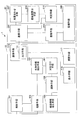
- FIG. 1 is a block diagram illustrating an example of the configuration of the authentication system 1 according to the first embodiment.
- An authentication system 1 illustrated in FIG. 1 includes a biological information processing apparatus 10 and an authentication apparatus 20.
- the biological information processing apparatus 10 is an information processing apparatus that extracts biological information and auxiliary information and outputs the associated biological information and auxiliary information to the authentication apparatus 20.
- the authentication device 20 is a server or the like that performs authentication processing using biometric information and auxiliary information acquired from the biometric information processing device 10.
- the biological information processing apparatus 10 includes an irradiation unit 101, an imaging unit 103, an auxiliary information extraction unit 105, a biological information extraction unit 107, a tracking unit 109, an association unit 111, a communication unit 113, a display unit 115, and an opening / closing unit 117. .
- the user who wishes to enter the room holds his / her hand over the biological information processing apparatus 10 installed in or near the automatic door.
- the irradiation unit 101 detects that the palm is held up, the irradiation unit 101 irradiates the palm with near infrared light.
- the photographing means 103 photographs the palm irradiated with near infrared light.
- the biological information processing apparatus 10 may accept the user ID from an IC card, a keyboard, or the like.
- the photographing means 103 outputs a plurality of images taken in the time direction to the auxiliary information extracting means 105 and the biological information extracting means 107.
- the auxiliary information extraction unit 105 extracts auxiliary information indicating a part of the body photographed together with the biological information from the plurality of images photographed by the photographing unit 103.
- the auxiliary information is, for example, information on the outline of the palm or information on finger placement.
- the auxiliary information extracting unit 105 outputs the auxiliary information to the tracking unit 109 every time auxiliary information is extracted from the image in the order of photographing.
- the biometric information extraction unit 107 extracts biometric information from at least one of the plurality of images acquired from the imaging unit 103.
- the biological information is, for example, a vein image or a palm print.
- the biometric information extraction unit 107 outputs the extracted biometric information to the association unit 111.
- the tracking unit 109 tracks the auxiliary information extracted from the auxiliary information extracting unit 105 in the time direction.
- the tracking unit 109 replaces auxiliary information located outside the imaging range with an estimated value using a model of temporal change of auxiliary information.
- the tracking unit 109 performs tracking with the first auxiliary information extracted from the tracking target image and the second auxiliary information extracted from the image immediately before the tracking target image, and can cope with the auxiliary information. Depending on the number of models, the model of time change may be changed.
- the tracking unit 109 outputs the auxiliary information after tracking to the association unit 111.
- the auxiliary information after tracking is information including the replaced estimated value.
- the association means 111 associates the positional relationship between the auxiliary information extracted from the image from which the biological information is extracted and tracked, and the extracted biological information.
- the association unit 111 outputs the associated auxiliary information and biological information to the communication unit 113.
- the communication unit 113 outputs the auxiliary information and the biological information acquired from the association unit 111 to the authentication device 20 together with the authentication request or the registration request. Therefore, the communication unit 113 has a function as an output unit 114 that outputs auxiliary information and biological information.
- the communication unit 113 outputs the determination result to the display unit 115 and the opening / closing unit 117 when the authentication determination result is acquired from the authentication device 20.
- the display unit 115 notifies the user of the authentication result of the room permission by using a lamp or a buzzer. If the display unit 115 indicates that the determination result indicates that the user is not a registrant, the user is notified of the authentication result indicating that the entry is not permitted by a lamp, a buzzer, or the like.
- the opening / closing means 117 controls to open the automatic door if the determination result indicates that the user is a registrant. If the determination result indicates that the user is not a registrant, the opening / closing means 117 controls the automatic door to remain closed.
- the irradiation means 101, the imaging means 103, the display means 115, and the opening / closing means 117 of the biological information processing apparatus 10 are not necessarily required for the biological information processing apparatus 10, and each of these means is provided in another apparatus. May be.
- the biological information processing apparatus 10 can also register auxiliary information and biological information in the authentication apparatus 20.
- the biometric information processing apparatus 10 accepts a user ID from an IC card or a keyboard when making a registration request, and transmits the user ID to the authentication apparatus 20 together with biometric information.
- the authentication device 20 includes a communication unit 201, a registration unit 203, a storage unit 205, an alignment unit 207, a similarity calculation unit 209, and a determination unit 211.
- the communication unit 201 determines whether it is a registration request or an authentication request when the auxiliary information and the biometric information are acquired.
- the communication unit 201 outputs the auxiliary information, biometric information, and user ID received together with the registration request to the registration unit 203. Further, the communication unit 201 outputs the auxiliary information and the biometric information received together with the authentication request to the alignment unit 207.
- the registration unit 203 records the acquired ID as a registrant ID in the storage unit 205 in association with auxiliary information and biometric information.
- the storage unit 205 stores the registered registrant ID, auxiliary information, and biometric information in association with each other.
- the registration unit 207 uses the auxiliary information stored in the storage unit 205 to perform registration of the vein image that is biometric information.
- the alignment unit 207 uses the biometric information of the corresponding ID, and otherwise uses the biometric information of all IDs in order.
- the alignment unit 207 outputs the biometric information after the alignment to the similarity calculation unit 209.
- the similarity calculation unit 209 calculates the similarity between the registered biometric information and the biometric information to be authenticated.
- the degree of similarity indicates that the larger the value, the more similar.
- the similarity calculation unit 209 outputs the calculated similarity to the determination unit 211.
- the determination unit 211 determines whether the calculated similarity is greater than a predetermined threshold value. The determination result is transmitted to the biological information processing apparatus 10 via the communication unit 201.
- palm fingerprints can be considered as biometric information other than veins that can be used in each embodiment.
- the embodiments can also be applied to a case where a plurality of finger veins or fingerprints are photographed without contacting the photographing device 103.
- the type of biometric information used for authentication is not limited.
- Auxiliary information assumed in each embodiment can be taken together with biometric information such as contour shape and finger position, and part of the information can be out of the shooting range when the hand is close to the shooting device. However, some features are within the shooting range.
- the irradiation means 101 for example, an LED that emits near-infrared light is preferably used.
- the irradiation unit 101 desirably uses visible light when a palm print is used as biological information.
- the photographing means 103 is preferably a CMOS camera or a CCD camera provided with a filter (visible cut filter) that blocks visible light.
- FIG. 2 is a diagram illustrating an example of the photographing apparatus 301 according to the first embodiment.
- the irradiation unit 101 and the photographing unit 103 are integrated.
- the palm is held from above the photographing apparatus 301.
- the shooting result is expressed as a moving image.
- a moving image is a sequence of images taken at a predetermined time interval. For example, 33 milliseconds is used as the time interval.
- Each image constituting the moving image is a two-dimensional array including a large number of pixels, and each pixel has a value (pixel value) corresponding to the intensity of light.
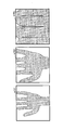
- FIG. 3 is a diagram illustrating an example of each image included in a captured moving image. In the example shown in FIG. 3, three images are shown.
- each image shown in FIG. 3 is an image obtained by photographing a state where the hand gradually approaches the photographing apparatus 301.
- the image size is set to 100 ⁇ 100, for example.
- auxiliary information extraction unit 105 can extract auxiliary information by ternizing the captured image as follows.
- the auxiliary information extraction unit 105 sets the value “0” representing the background when the value of each pixel is larger than the predetermined first threshold value.
- A2 When the value of each pixel is smaller than the predetermined first threshold value and larger than the second threshold value ( ⁇ first threshold value), the auxiliary information extracting unit 105 determines the value “ 2 ”.
- A3 In the cases other than the above, the auxiliary information extraction unit 105 sets the value “1” representing the vein.
- a value smaller than the average background pixel value is set as the first threshold value.
- the first threshold value is, for example, the value “150”.
- a value smaller than the first threshold is set as the second threshold.
- the second threshold value is set to a value larger than the average vein image pixel value. For example, the second threshold is a value “60”.
- the auxiliary information extraction unit 105 scans all the pixels one by one, and the target pixel is the value “2” representing the palm, and the adjacent pixel is the value “0” representing the background. ", The value of the target pixel is changed to a value" 4 "representing the contour. Finally, the auxiliary information extraction unit 105 obtains the coordinate value of the pixel representing the contour by the following method.
- the auxiliary information extraction unit 105 prepares an array for storing coordinate values. A variable for storing the number of points is prepared and initialized to “0”. (B2) The auxiliary information extraction unit 105 scans the above image, and when there is a pixel having a value “4” representing the contour, the coordinate value is recorded in the array, and the value of the variable for storing the number of points Is increased by one. Thereby, contour information as auxiliary information is extracted.
- the auxiliary information extraction unit 105 can perform extraction as follows based on, for example, a ternary image similar to the contour extraction method described above. Here, it is assumed that the palm is held up so that the finger comes to the upper side of the image.
- the auxiliary information extraction unit 105 scans from the top pixel of the image in the downward direction of the image, and when there is a change from the value “0” representing the background to the value “2” representing the palm, The value of the pixel is changed to a value “5” representing the candidate for attaching.
- the auxiliary information extraction unit 105 sequentially scans all the pixels of the image one by one, and if a pixel having a value “5” representing a candidate for splicing is found, examines the values of the left and right pixels. If the values of the left and right pixels are both the value “2” representing the palm, the auxiliary information extracting unit 105 changes the value “5” to the value “6” representing falseness.
- the auxiliary information extraction unit 105 stores the coordinate value of the pixel representing finger sticking in the array in the same manner as in the contour extraction.
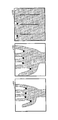
- FIG. 4 is a diagram illustrating an example of extraction of finger sticking for each image.
- the coordinate system representing the coordinate values is expressed by a coordinate system in which the origin is at the upper left of the image, the horizontal direction is the x axis (right image positive), and the vertical direction is the y axis (image lower right). To do.
- FIG. 5 is a diagram showing an example of the extraction result of tsuke.
- the first image shown in FIG. 5 shows an image a101
- the second image shows an image a103
- the third image shows an image a105.
- the third sheet only two pieces of auxiliary information can be extracted because the hand is too close to the photographing apparatus or the user's hand is large.
- the biometric information extraction unit 107 has described the method of extracting together with auxiliary information as one method of extracting veins as an example of biometric information.
- the biological information extracting unit 107 may extract a pixel indicating the value “1”.
- the biological information extraction unit 107 extracts a vein from the image shown in FIG.
- the biological information extraction unit 107 cannot extract a vein image from the first image a101 and the second image a103 shown in FIG. This is because the first image and the second image are separated from an appropriate position from the photographing apparatus.
- the biometric information extraction unit 107 extracts biometric information from the third image a105.
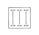
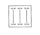
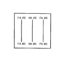
- FIG. 6 is a diagram illustrating an example of the extracted biological information.
- the vein image is composed of three line segments, the first line segment is (20, 20), (20, 80), and the second line segment is (50, 20), (50, 80), and the third line segment has (80, 20), (80, 80) as end points, respectively.
- a simple vein image is shown for ease of explanation.
- the auxiliary information is expressed as an array of coordinate values
- the vein image is expressed as a binary image.
- the coordinate value of a point constituting a vein image or the coordinate value of a feature point such as a vertex, a branch point, or an end point of each broken line when the vein image is thinned and approximated by a broken line can be considered.
- any expression form of the vein image may be used.
- the tracking unit 109 tracks auxiliary information extracted for each image in the time direction.
- auxiliary information extracted for each image in the time direction.
- the initialization tracking unit 109 prepares an array for storing the positions of the initialized spears.
- the tracking unit 109 prepares a variable indicating whether or not a value is set in this array, and sets a value indicating unset.
- the presence confirmation tracking unit 109 determines whether there is data (auxiliary information) to be processed as data presence confirmation. When there is no more data due to the end of the authentication process, the tracking unit 109 ends the process.
- the auxiliary information reading / tracking means 109 reads the position of the false for one tracking target image among the auxiliary information reading moving images.
- one or a plurality of spices extracted from the tracking target image are also referred to as a first spear or a current spear.
- the tracking unit 109 stores the position of the first attachment and changes the variable indicating the presence or absence of storage to a value indicating the set state.
- the tracking means 109 arranges the individual hooks in a line according to a predetermined standard and stores them in the array in that order.
- the auxiliary information correspondence tracking means 109 associates the second attachment with the first attachment.
- the second attachment is also referred to as previous attachment and refers to one or more attachments extracted from the image immediately before the tracking target image. Details of the association will be described later.
- the tracking unit 109 determines that the part of the second attachment that has not been matched has come out of the imaging range, estimates the attachment position, and uses the estimated position instead. Use. Thereby, even when auxiliary information falls outside the imaging range, it is possible to compensate for the loss of auxiliary information. Based on the obtained association, the first attachments are arranged so that the corresponding attachments are in the same order. The tracking unit 109 stores the arranged results in an array. Thereafter, the tracking unit 109 repeats the above processing for the next image after the moving image.
- the tracking means 109 is, for example, a second weight that has the smallest distance (the mean square of the difference in coordinate values) with respect to one of the first weights (also referred to as a corresponding target weight). Associate.
- the tracking unit 109 sets “no correspondence” for the corresponding target attachment.
- the first tick is arranged in a row in an appropriate manner, giving a number starting from 1.
- An appropriate method is, for example, arranging the false marks in ascending order of the coordinate values in the horizontal direction.
- m is the number of corresponding falses
- mn is the number of falses that exist only in the first one
- kn is the number of falses that exist only in the second one.
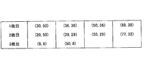
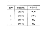
- FIG. 7 is a diagram illustrating a correspondence relationship of auxiliary information between the first sheet (previous position) and the second sheet (current position).
- FIG. 8 is a diagram illustrating a correspondence relationship of auxiliary information between the second sheet (previous position) and the third sheet (current position).
- the tracking unit 109 models the time change of the auxiliary information.
- the coordinate value of the false on the photographed image changes every moment, but there is a certain rule depending on how to hold the change.
- s is a magnification and is a positive real number
- cx and cy are the optical axis center of the camera, which is substantially equal to the image center.
- the tracking means 109 obtains model parameters.
- the model parameter is an enlargement factor s.
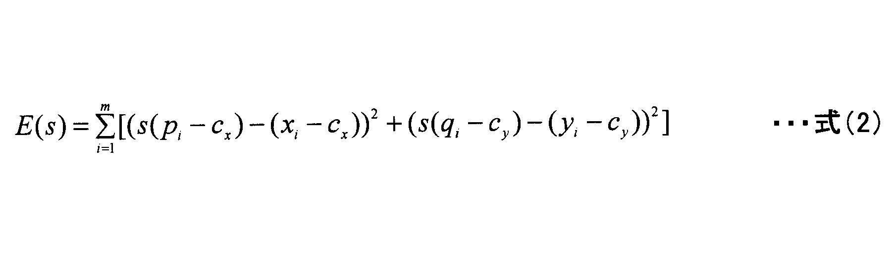
- the least square method is used to calculate the model parameter. Specifically, s that minimizes the following evaluation function is defined as a solution.
- the tracking means 109 can easily minimize the above evaluation function because it is a quadratic expression for s. This solution is shown below.
- the position (xi, yi) of is estimated by the following equation.
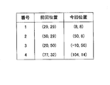
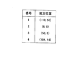
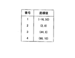
- FIG. 9 shows the result including the estimated value by the above equation (4) in the association between the second sheet and the third sheet shown in FIG.
- FIG. 9 is a diagram illustrating an example of associated auxiliary information including an estimated value.
- the attachment of the current positions of numbers 3 and 4 shown in FIG. 9 is outside the shooting range, but an estimated value is inserted.
- the tracking means 109 uses, for example, affine transformation as a model for allowing a more free holding.
- affine transformation is transformation including two-dimensional translation, rotation, and enlargement / reduction. It is expressed as follows using mathematical formulas.
- ax, bx, cx, ay, by, cy are unknown parameters representing the affine transformation. These parameters can also be determined by, for example, the least square method. In this case, the tracking unit 109 uses a parameter that minimizes the following evaluation function as a solution.
- the number of affine transformation unknown parameters is 6, in order to obtain a solution, it is necessary that the number m of the corresponding anchors be 3 or more. When m is smaller than 3, for example, it is conceivable that the user is held over again as a tracking failure.
- a simpler transformation than the affine transformation for example, a similarity transformation is considered.
- the position (xi, yi) is estimated by the following equation.
- the projective transformation is a model when the shape of the palm is regarded as a plane in a three-dimensional space and the optical system of the photographing means 103 is regarded as perspective projection, and can also be applied when the palm is tilted.
- determination of model parameters requires four points of correspondence.
- the tracking unit 109 may change the model to be used based on the number of associated auxiliary information.
- the tracking unit 109 uses, for example, a projective transformation model when m is 4, uses an affine transformation model when m is 3, uses a similarity transformation model when m is 2, and uses m when 1.
- An enlargement / reduction model may be used.
- a contour is used as auxiliary information. Unlike finger tapping, the points constituting the contour are connected, and the corresponding points between the previous contour and the current contour are not easily obtained.
- the following two methods are conceivable.
- -A method for selecting characteristic points from the points that form the contour-A method for modeling change over time of points constituting the contours and determining conversion parameters without taking corresponding points For example, it is conceivable to use a maximum point of curvature (a point where the bending is large). Instead, the tracking unit 109 may select several points whose angle between two lines connecting two points separated from the target point by a certain pixel (for example, 5 pixels) is farthest from 180 degrees. After selecting a characteristic point, it can be tracked in the same way as finger sticking.
- the tracking unit 109 prepares a variable that holds the minimum value of the sum of the initialization distances and the enlargement ratio at that time. Set infinity or a sufficiently large value as the minimum value. The tracking unit 109 sets, for example, 0.5 as an initial value for the enlargement ratio s.
- the tracking means 109 converts the coordinates of each point forming the boundary at this time with the enlargement ratio set for the distance calculation.
- the tracking unit 109 obtains the point that forms the previous boundary closest to the converted coordinate value, and obtains the sum of the distances to that point.
- the tracking unit 109 increases the change rate s of the enlargement rate by an appropriate step size (for example, 0.1).
- the tracking unit 109 ends when the upper limit (for example, 2) is reached.
- the tracking means 109 can also set a threshold regarding the distance, as in the case of tracking the finger.
- the associating means 111 collects the auxiliary information obtained by tracking and the extracted biological information into a set of data.
- the association unit 111 does not associate an image for which biometric information has not been obtained.
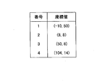
- FIG. 10 and FIG. 11 show the results associated with the example of the moving image shown in FIG.
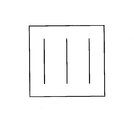
- FIG. 10 is a diagram showing an example of biological information.
- FIG. 11 is a diagram illustrating an example of auxiliary information after tracking. In the example shown in FIG. 11, the coordinates are rearranged in ascending order.
- the association unit 111 associates the biological information shown in FIG. 10 with the auxiliary information shown in FIG.
- the storage unit 205 of the authentication device 20 stores a user ID, auxiliary information, and a vein image as biometric information in association with each other.
- the storage unit 205 is typically realized in the authentication device 20 as a database of the following format.
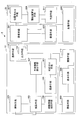
- FIG. 12 is a diagram showing an example of a database related to biological information.
- the auxiliary information and the vein image are stored after being converted into a string of numbers according to a certain rule.
- the auxiliary information score and the horizontal / vertical coordinate value column are used.
- the vein image is represented by an image, the pixel value is one column. The number sequence is used.
- FIG. 13 is a diagram showing an example of registered biometric information.
- the example shown in FIG. 13 is an image of a vein image as registered biological information.
- FIG. 14 is a diagram illustrating an example of registration assistance information.
- the biometric information shown in FIG. 13 and the auxiliary information shown in FIG. 14 are registered in the user ID “0001” shown in FIG.
- the auxiliary information shown in FIG. 14 is arranged in the order of the number (4) and the coordinate value from the smallest coordinate value in the order of horizontal (x) vertical (y), “4, ⁇ 12, 50,. Is registered in the storage means 205.
- the biometric information shown in FIG. 13 has pixel values arranged in a line in a predetermined order, and “0,..., 1, 0,. Is registered in the storage means 205.
- Positioning means ⁇ Positioning means >> Next, an example of a method for performing alignment using auxiliary information will be described. Here, a case where only alignment by parallel movement is performed is handled. For example, it is assumed that the movement amount of the coordinate value of the registered data is determined with reference to the coordinate of the collation data.
- the alignment unit 207 prepares a variable that holds the sum of the coordinate values of the auxiliary information as initialization, and initializes it to zero. Initialization processing is performed separately for the x and y coordinates.
- the alignment unit 207 calculates the sum of the coordinate values of the auxiliary information for each of the registration data and the collation data.
- the alignment unit 207 calculates the center of gravity position by dividing the sum of coordinate values by the number of auxiliary information.
- the alignment unit 207 calculates a movement amount by subtracting the center of gravity position on the registration data side from the center of gravity position on the collation data side.
- the positioning means 207 obtains (2, 1). Accordingly, the vein image of the registered data after alignment is as shown in FIG.
- FIG. 15 is a diagram showing an example of biometric information after alignment.
- the example shown in FIG. 15 is an example in which the biological information shown in FIG. 13 is moved (2, 1).
- the positioning means 207 can use a complicated moving method so as to cope with them.
- the alignment unit 207 can also perform alignment using both auxiliary information and a vein image. In the embodiment, any method may be used as the alignment processing method.
- FIG. 16 is a diagram illustrating an example of biometric information after alignment in the case of no tracking.
- the biometric information shown in FIG. 16 is shifted by “1” in the y direction compared to the biometric information shown in FIG.
- Similarity calculation means When the vein image is expressed as a binary image, the similarity calculation unit 209 calculates the similarity by, for example, the following method.
- the similarity calculation unit 209 sets the target pixel at the upper left of the image.
- a variable (counter) that holds the number of matched pixels and a variable that holds the number of pixels forming a vein image are prepared and initialized to 0, respectively.
- the similarity calculation unit 209 acquires and compares pixel values of two images in the target pixel.
- the similarity calculation means 209 increases the value of the coincidence counter by one if both represent vein images. If either of them represents a vein image, the value of the vein image counter is incremented by one.
- the similarity calculation means 209 moves the attention pixel to the right by one. When the target pixel is the right end, the similarity calculation unit 209 moves the target pixel to the lower left one. If the target pixel is in the lower right, the similarity calculation process ends.
- the similarity calculation results for the extraction example shown in FIG. 11 and the registered data example shown in FIG. 15 are as follows. 162/186 ⁇ 0.871
- the similarity calculation result is as follows. 159/189 ⁇ 0.841 As a result, it can be seen that the positioning becomes more accurate and the similarity is improved by tracking the auxiliary information.
- the determination unit 211 compares the similarity calculated by the similarity calculation unit 209 with a preset threshold Th, and determines that the user is one of the person or the registrant if the similarity is larger than the threshold Th.
- An example of how to determine the threshold Th is as follows. Biological information of a large number of people is collected for evaluation, and the acceptance rate of other people (the rate at which other people's collation data is erroneously determined as the person) is calculated for these biometric information and various threshold values. A threshold value at which this other person acceptance rate is 1/1000 (the same accuracy as a 4-digit password) may be examined, and the threshold value may be set as the threshold value Th.
- the determination unit 211 determines the identity.
- the determination unit 211 determines that the person is the person himself / herself. Therefore, the biometric authentication system can be improved by tracking the auxiliary information.
- the determination result is transmitted to the biological information processing apparatus 10 so that, for example, opening / closing of an automatic door is controlled.
- FIG. 17 is a flowchart illustrating an example of the authentication process according to the first embodiment.
- step S101 shown in FIG. 17 when the irradiation unit 101 detects that the palm is held over, the irradiation unit 101 irradiates the palm with near infrared light.
- the part of the body which acquires biometric information gives a palm as an example, it is not restricted to a palm.
- step S102 the photographing means 103 photographs the palm irradiated with near infrared light.
- the user ID may be received from an IC card, a keyboard, or the like.
- the auxiliary information extraction unit 105 extracts auxiliary information indicating a part of the body photographed together with the biological information from the plurality of images photographed by the photographing unit 103.
- the auxiliary information is, for example, information on the outline of the palm or information on finger placement.
- step S ⁇ b> 104 the biological information extraction unit 107 extracts biological information from at least one of the plurality of images acquired from the imaging unit 103.
- the biological information is, for example, a vein image or a palm print.
- step S105 the tracking unit 109 tracks the auxiliary information extracted from the auxiliary information extracting unit 105 in the time direction.
- the tracking unit 109 replaces auxiliary information located outside the imaging range with an estimated value using a model of temporal change of auxiliary information.
- the tracking unit 109 performs tracking with the first auxiliary information extracted from the tracking target image and the second auxiliary information extracted from the image immediately before the tracking target image, and can cope with the auxiliary information.
- the model of time change may be changed.
- step S106 the association unit 111 associates the positional relationship between the auxiliary information that is extracted from the image from which the biological information is extracted and tracked, and the extracted biological information.
- step S107 the registration unit 207 uses the registered auxiliary information stored in the storage unit 205 to perform registration of the vein image that is biometric information.
- step S108 the similarity calculation unit 209 calculates the similarity between the registered biometric information (registration data) and the biometric information to be authenticated (collation data).
- step S109 the determination unit 211 determines whether the calculated similarity is greater than a predetermined threshold value.
- the determination result is transmitted to the biological information processing apparatus 10 via the communication unit 201.
- step S110 the opening / closing means 117 controls to open the automatic door if the determination result indicates that the user is a registrant. If the determination result indicates that the user is not a registrant, the opening / closing means 117 controls the automatic door to remain closed.
- step S103 and steps S104 to S105 is not performed in any order.
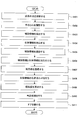
- FIG. 18 is a flowchart illustrating an example of auxiliary information tracking processing according to the first embodiment.
- the tracking unit 109 prepares an array for storing the initialized position of the spear.
- the tracking unit 109 prepares a variable indicating whether or not a value is set in this array, and sets a value indicating unset.
- step S202 the tracking unit 109 determines whether or not there is data (auxiliary information) to be processed as data confirmation. If there is auxiliary information (step S202—YES), the process proceeds to step S203, and if there is no auxiliary information (step S202—NO), the process ends.
- step S203 the tracking unit 109 reads the position of the false for one image to be tracked among the auxiliary information reading moving images.
- step S204 the tracking unit 109 determines whether it is the case of the initial process. If it is the first process (step S204—YES), the process proceeds to step S202. If it is not the first process (step S204—NO), the process proceeds to step S205.
- step S205 the tracking unit 109 associates the second hook with the first hook. Thereafter, the tracking unit 109 repeats the above processing for the next image after the moving image.
- FIG. 19 is a flowchart illustrating an example of biometric information and auxiliary information registration processing according to the first embodiment.
- the biological information processing apparatus 10 inputs the ID of a user who desires registration from an IC card, a key, or the like.
- steps S301 to S306 is the same as the processing of steps S101 to S106 shown in FIG.
- the communication unit 113 transmits the user ID, auxiliary information, and biometric information to the authentication device 20.
- step S307 the registration unit 203 records the user ID, auxiliary information, and biological information acquired via the communication unit 201 in the storage unit 205. Thereby, the biometric information associated with the tracked auxiliary information can be registered.
- auxiliary information can be estimated and acquired by tracking even for a large hand that does not fit in the imaging range.
- a large hand means a hand whose auxiliary information is not included in the shooting range.
- Example 2 Next, an authentication system according to the second embodiment will be described.
- the first embodiment it is assumed that a part of the auxiliary information can be traced.
- the auxiliary information may not be tracked. Therefore, in the second embodiment, the user is guided so that as much auxiliary information as possible is captured.
- FIG. 20 is a block diagram illustrating an example of the configuration of the authentication system 2 according to the second embodiment.
- the same components as those in the authentication system 1 shown in FIG. Hereinafter, a configuration different from the first embodiment will be mainly described.
- the association unit 301 of the biological information processing apparatus 15 notifies the associated auxiliary information and the biological information to the communication unit 113 and also notifies the guidance unit 303.
- the guiding unit 303 predicts the position of the auxiliary information based on the time change of the auxiliary information, and if the predicted auxiliary information is outside the shooting range, guides the user to a position that falls within the shooting range. For example, the guiding unit 303 controls the display unit 305 to be guided by voice, or controls to guide by the LED or the like.
- the display unit 305 displays the position held by the user's hand using voice, LED, or the like according to an instruction from the guiding unit 303. Next, main processing in the second embodiment will be described.
- the guidance unit 303 can predict auxiliary information that will be included in the imaging range and auxiliary information that will protrude from the imaging range in the future by tracking auxiliary information. Since guidance that greatly changes the user's movement is not convenient, the guidance means 303 basically guides the auxiliary information in the direction in which the auxiliary information remains most within a certain range from the predicted destination.
- the distance information is obtained by a means for measuring the distance to the palm separately from the normal shooting.
- a method using a distance measuring device other than a camera and a method of calculating a distance from a photographing result using pattern light with an illumination device for projecting pattern light are conceivable.
- the distance information acquisition method may be any known technique.
- a distance range in which biological information can be extracted is obtained in advance by an evaluation experiment or the like. Here, it is assumed that the distance decreases with a hand-holding.
- the guiding means 303 inputs distance information at the time of acquiring the current captured image. This distance information is set to d2.
- the guiding unit 303 estimates that the previous and current images can be extracted from the previous and current images if the previous distance information and the current distance information are within the imageable range of the biological information. In this case, the guiding means 303 does not guide the user because it has already been photographed.
- the guiding unit 303 distinguishes between a large hand away from the photographing apparatus and a small hand near the photographing apparatus.
- a clue that can be used for this distinction is, for example, the brightness of the hand.
- the biological information processing apparatus 10 By measuring the standard hand brightness for each distance in advance, the biological information processing apparatus 10 creates a correspondence table of brightness and distance.
- the guiding unit 303 can obtain the distance from the brightness of the captured image and this correspondence table.
- the subsequent processing is the same as when distance information is used.
- the guiding unit 303 estimates the position of each auxiliary information in the next captured image.
- the position is estimated by, for example, linear extrapolation of the current position and the previous position.
- the guiding unit 303 estimates the next distance by regarding the movement of the hand as being constant with respect to the distance.
- the guiding unit 303 may estimate the position of the auxiliary information on the assumption that the position of each auxiliary information from the optical axis center is inversely proportional to the distance.
- FIG. 21 is a diagram illustrating an example of estimated auxiliary information.
- the guiding means 303 determines the guiding direction.
- it is estimated that only two points are within the photographing range as shown in FIG. 7 For example, when the number of points is increased most in the range up to 6 pixels, it can be considered that the pixel moves to the left by 6 pixels on the screen.
- the guiding means 303 guides the user to move the palm slightly to the left side of the screen. In addition, as a result of guidance, there is a possibility of deteriorating too far to the left. In such a case, the guiding unit 303 instructs to hold the hand again.
- FIG. 22 is a diagram showing an example of biological information after guidance.
- FIG. 23 is a diagram illustrating an example of auxiliary information after guidance.
- FIG. 22 is obtained as a vein image of the third biological information, and
- FIG. 23 is obtained as auxiliary information.
- Similarity calculation and judgment process For the example of biometric information after guidance shown in FIG. 23 and the registered data example shown in FIG. 13, the similarity calculation unit 209 calculates the similarity when the same similarity calculation method as that of the first embodiment is used. .
- the similarity calculation unit 209 obtains the following similarity. 165/183 ⁇ 0.902 It can be seen that the guidance means 303 makes the alignment more accurate and improves the similarity.
- the threshold value Th is set to 0.85 by the determination means 211, the person is determined to be the person himself. However, even if the threshold value Th is increased to 0.90 in order to further reduce the acceptance rate of others, the person is similarly determined. .
- FIG. 24 is a flowchart illustrating an example of the authentication process according to the second embodiment.
- the processing in steps S401 to S406 shown in FIG. 24 is the same as the processing in steps S101 to S106 shown in FIG.
- step S407 the guidance unit 303 tracks auxiliary information, thereby predicting auxiliary information that will fall within the shooting range and auxiliary information that will protrude from the shooting range.
- the guiding means 303 performs guidance so that auxiliary information enters the imaging range based on this prediction.
- steps S408 to S411 is the same as the processing of steps S107 to S110 shown in FIG.
- the second embodiment it is possible to increase the continuity of the auxiliary information tracking process by guiding the user in a direction in which the auxiliary information can be optimally acquired. Thereby, even when auxiliary information is not included in the imaging range at an appropriate imaging position, the authentication accuracy of the biological information can be improved.
- the biometric information processing device of each embodiment may include an authentication device and perform biometric authentication processing.
- an authentication device As a biological information processing apparatus, ATM (Automatic teller ⁇ machine), PC (Personal Computer), and the like can be considered.
- Example 3 Next, an information processing apparatus according to the third embodiment will be described.
- the processing described in the first and second embodiments is performed by an information processing apparatus such as a PC or a server.
- FIG. 25 is a block diagram illustrating an example of the configuration of the information processing apparatus 30 according to the third embodiment. 25 includes at least a control unit 401, a main storage unit 403, an auxiliary storage unit 405, a communication unit 407, a recording medium I / F unit 409, an input unit 411, a display unit 413, and a camera 415. . Each unit is connected via a bus so that data can be transmitted / received to / from each other.
- the control unit 401 is a CPU (Central Processing Unit) that controls each device, calculates and processes data in a computer.
- the control unit 401 is an arithmetic device that executes a program stored in the main storage unit 403 or the auxiliary storage unit 405.
- the control unit 401 receives data from the communication unit 407 or each storage unit, calculates, processes, and outputs the data. And output to each storage unit.
- control unit 401 can perform the output process of biometric information and auxiliary information by executing the processing program of the first and second embodiments stored in the auxiliary storage unit 405, for example.
- the main storage unit 403 is a ROM (Read Only Memory), a RAM (Random Access Memory), or the like, and a storage device that stores or temporarily stores programs and data such as an OS and application software that are basic software executed by the control unit 401 It is.
- ROM Read Only Memory
- RAM Random Access Memory
- the auxiliary storage unit 405 is an HDD (Hard Disk Drive) or the like, and is a storage device that stores data related to application software. Further, the auxiliary storage unit 405 may store the processing program of the first and second embodiments acquired from the recording medium 417 or the like, the image acquired from the communication unit 407, and the like.
- the communication unit 407 performs communication through a wired or wireless network.
- a recording medium I / F (interface) unit 409 is an interface between the information processing apparatus 30 and a recording medium 417 (for example, a flash memory) connected via a data transmission path such as a USB (Universal Serial Bus).
- a recording medium 417 for example, a flash memory
- USB Universal Serial Bus
- a processing program is stored in the recording medium 417, and the processing program stored in the recording medium 417 is installed in the information processing apparatus 30 via the recording medium I / F unit 409.
- the installed processing program can be executed by the information processing apparatus 30.
- the input unit 411 includes a keyboard having cursor keys, numeric input, various function keys, and the like, and a mouse and a slide pad for selecting keys on the display screen of the display unit 413.
- the input unit 411 is a user interface for the user to give an operation instruction to the control unit 401 or input data.
- the display unit 413 is, for example, an LCD (Liquid Crystal Display) or the like, and performs display according to display data input from the control unit 401.
- LCD Liquid Crystal Display
- the camera 415 is a CMOS camera or a CCD camera, for example, and shoots a part of the body with a moving image.
- the storage means of the first and second embodiments can be realized by the auxiliary storage unit 405, for example.
- the photographing means of the first and second embodiments can be realized by the camera 415, for example.
- the communication means of the first and second embodiments can be realized by the communication unit 407, for example.
- the other means of the first and second embodiments can be realized by the control unit 301 and the main storage unit 303 as a working memory, for example.
- the program executed by the information processing apparatus 30 has a module configuration including each means other than the storage means described in the first and second embodiments.
- the control unit 401 reads out and executes a program from the auxiliary storage unit 405, one or more of the above-described units are loaded onto the main storage unit 403, and one or more of the respective units are loaded. Means are generated on the main storage unit 403.
- the biological information processing in each of the embodiments can be performed by a computer.
- the biometric information processing described above can be realized by recording this program on a recording medium and causing the computer or portable device to read the recording medium on which the program is recorded.
- the recording medium is a recording medium that records information optically, electrically, or magnetically, such as a CD-ROM, flexible disk, magneto-optical disk, etc., and information is electrically recorded, such as a ROM, flash memory, etc.
- Various types of recording media such as a semiconductor memory can be used. Note that the recording medium does not include a carrier wave.
- the biological information processing apparatus, the biological information processing method, and the program have been described above according to each embodiment. However, the present invention is not limited to the above-described embodiments, and various modifications and modifications are possible within the scope described in the claims. It can be changed. It is also possible to combine all or a plurality of the constituent elements of the above-described embodiments.
Landscapes
- Engineering & Computer Science (AREA)
- General Physics & Mathematics (AREA)
- Human Computer Interaction (AREA)
- Physics & Mathematics (AREA)
- Multimedia (AREA)
- Theoretical Computer Science (AREA)
- General Health & Medical Sciences (AREA)
- Health & Medical Sciences (AREA)
- Vascular Medicine (AREA)
- Oral & Maxillofacial Surgery (AREA)
- Computer Vision & Pattern Recognition (AREA)
- Collating Specific Patterns (AREA)
- Image Input (AREA)
- Measurement Of The Respiration, Hearing Ability, Form, And Blood Characteristics Of Living Organisms (AREA)
Abstract
Description
例えば、誘導を行う従来技術では、補助情報が撮影範囲に入らないくらい手が大きい場合には、撮影装置の位置から手の位置を遠ざけて補助情報が撮影範囲内に入るようにする。課題としては、手を遠ざけた場合、撮影装置の位置から手が遠くなるため、撮影装置の照明による明るさが不十分となり、撮影品質が低下し、生体情報を適切に抽出できないことが挙げられる。
例えば、補助情報の取得ができなかった場合に、補助情報を使用しない従来の認証処理を行う方法が考えられる。課題としては,補助情報が利用できないため、認証精度が低下することが挙げられる。
例えば、動画像から顔のベストショットを選び出す構成を、補助情報の取得処理に適用することが考えられる。しかし、課題としては、1つ目と同様、撮影装置の位置から手が遠い位置にあると、撮影装置の照明による明るさが不十分となり、撮影品質が低下し、生体情報を適切に抽出できないことが挙げられる。
10 生体情報処理装置
20 認証装置
103 撮影手段
105 補助情報抽出手段
107 生体情報抽出手段
109 追跡手段
111、301 対応付け手段
114 出力手段
303 誘導手段
401 制御部
403 主記憶部
405 補助記憶部
415 カメラ
<構成>
まず、実施例1における認証システムについて説明する。実施例1における認証システム1は、生体情報として手のひらの静脈を用い、自動ドアと組み合わせて入室管理に適用した認証システムを例に説明する。なお、開示の技術が、自動ドアと生体認証を組み合わせる例に限られないことは言うまでもない。
次に、生体情報処理装置10の各手段の処理の具体例を説明する。
照射手段101は、例えば、近赤外光を発光するLEDを用いることが好ましい。また、照射手段101は、生体情報として掌紋を用いる場合は、可視光を用いることが望ましい。撮影手段103は、可視光線を遮断するフィルタ(可視カットフィルタ)を付けたCMOSカメラあるいはCCDカメラを使用することが好ましい。
まず、補助情報として輪郭を用いる場合を想定して、輪郭を抽出する1手法を説明する。本手法の場合、静脈像も併せて抽出する。撮影された画像上で、背景は明るく、手のひらはやや暗く、静脈は、最も暗いパターンとして表される。そのため、例えば、補助情報抽出手段105は、撮影された画像を以下のように3値化することで、補助情報を抽出することができる。
(A2)補助情報抽出手段105は、各画素の値が、定められた第1の閾値よりも小さく、第2の閾値(<第1の閾値)よりも大きい場合には、手のひらを表す値「2」とする。
(A3)補助情報抽出手段105は、上記以外の場合には、静脈を表す値「1」とする。
(B2)補助情報抽出手段105は、上記の画像を走査し、輪郭を表す値「4」の画素があった場合には、その座標を配列に記録し、点の個数を記憶する変数の値を1つ増加させる。これにより、補助情報としての輪郭の情報が抽出される。
(C2)補助情報抽出手段105は、画像の全画素を1つずつ順番に走査し、つけね候補を表す値「5」を持つ画素が見つかったら、その左右の画素の値を調べる。補助情報抽出手段105は、左右の画素の値が、ともに手のひらを表す値「2」であった場合には、値「5」を、つけねを表す値「6」に変更する。
生体情報抽出手段107は、生体情報の一例として静脈を抽出する1手法として、補助情報と一緒に抽出する方法を上述した。例えば、生体情報抽出手段107は、値「1」を示す画素を抽出すればよい。
追跡手段109は、画像毎に抽出された補助情報を時間方向に追跡する。以下では、補助情報として、指つけねと、手のひらの輪郭形状との場合について説明する。
補助情報として指つけねを用いる場合に、動画像において補助情報を追跡する1手法を説明する。
追跡手段109は、初期化されたつけねの位置を記憶する配列を用意する。追跡手段109は、この配列に値が設定されているかどうかを表す変数を用意し、未設定を表す値を設定する。
追跡手段109は、データの存在確認として、処理すべきデータ(補助情報)があるかどうかを判定する。認証処理の終了によりデータがなくなった場合には、追跡手段109は、処理を終了する。
追跡手段109は、補助情報の読み込み動画像のうち、追跡対象の1枚の画像に対するつけねの位置を読み込む。以下では、追跡対象画像から抽出された1又は複数のつけねを第1のつけねや今回のつけねとも称する。
追跡手段109は、初回処理の場合、以降の補助情報の対応付け処理を行わない。
追跡手段109は、第2のつけねと第1のつけねとを対応付ける。第2のつけねとは、前回のつけねとも称し、追跡対象画像の直前の画像から抽出された1又は複数のつけねを言う。対応付けの詳細は後述する。

ここで、sは拡大率であり正の実数、cx,cyはカメラの光軸中心であり、ほぼ画像中心に等しい。
追跡手段109は、上記の評価関数は、sについて2次式であるので、簡単に最小化することができる。この解は以下に示される。

図7、8の対応付けの例において、光軸中心を画像中心cx=50,cy=50として上式を用いて計算すると、それぞれs=1.5とs=2となる。つまり、手のひらが撮影装置に近づいたため、1枚目と2枚目とでは1.5倍に、2枚目と3枚目とでは2倍に拡大しているという結果となる。
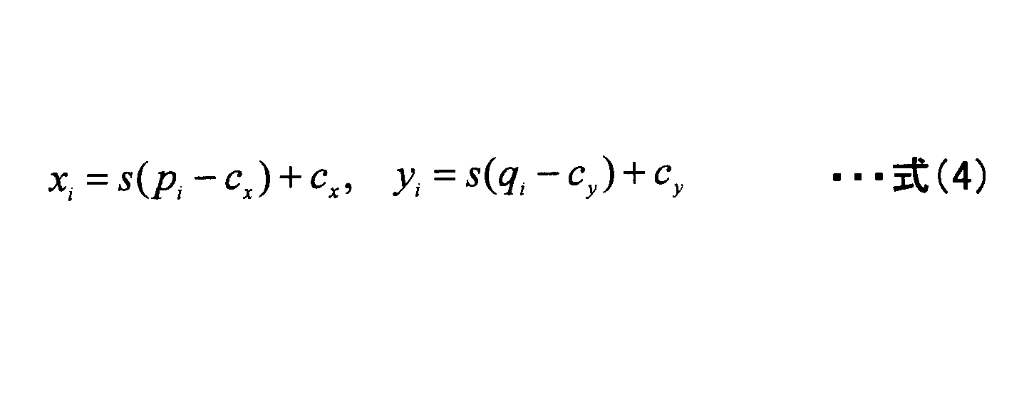
図8に示す2枚目と3枚目との対応付けにおいて、上式(4)による推定値を含めた結果を図9に示す。
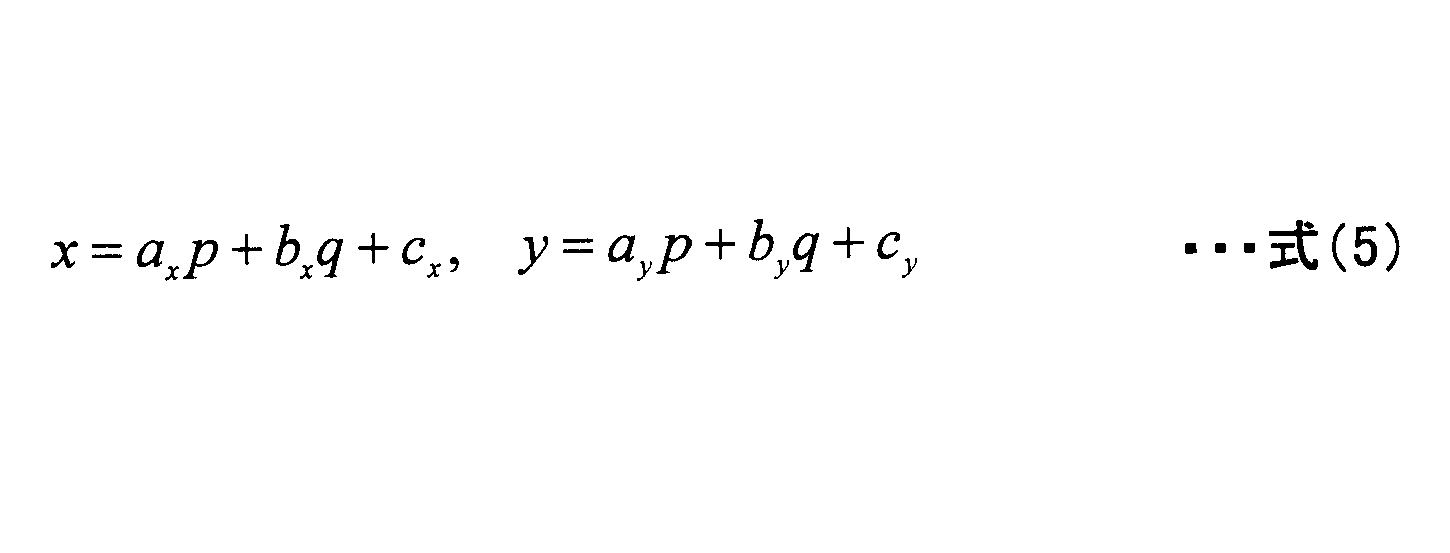
ここで、ax,bx,cx,ay,by,cyはアフィン変換を表す未知のパラメータである。これらのパラメータの決定も、例えば最小2乗法で行うことができる。この場合には、追跡手段109は、以下の評価関数を最小にするパラメータを解とする。

上記の評価関数は、未知パラメータについて2次式であるので、1階微分を0と置いた連立1次方程式を解くことで簡単に解を求めることができる。
相似変換は、アフィン変換でax=by,bx=-ayに限定したものである。従って、未知数のパラメータの個数が4になるため、追跡手段109は、対応するつけねの個数mが2であっても解を求めることができる。アフィン変換を用いる場合、第1のつけねと対応しない第2のつけね(pi,qi)(i=n+1,...,k)に対して、追跡手段109は、追跡対象画像上での位置(xi,yi)を下式で推定する。

さらに、自由なかざし方を認める他のモデルとしては、例えば射影変換が考えられる。数式を用いると以下のように表される。第2のつけねのうちの1つのつけねの位置を(p,q),対応する第1のつけねの位置を(x,y)とすると、下式が成り立つ。
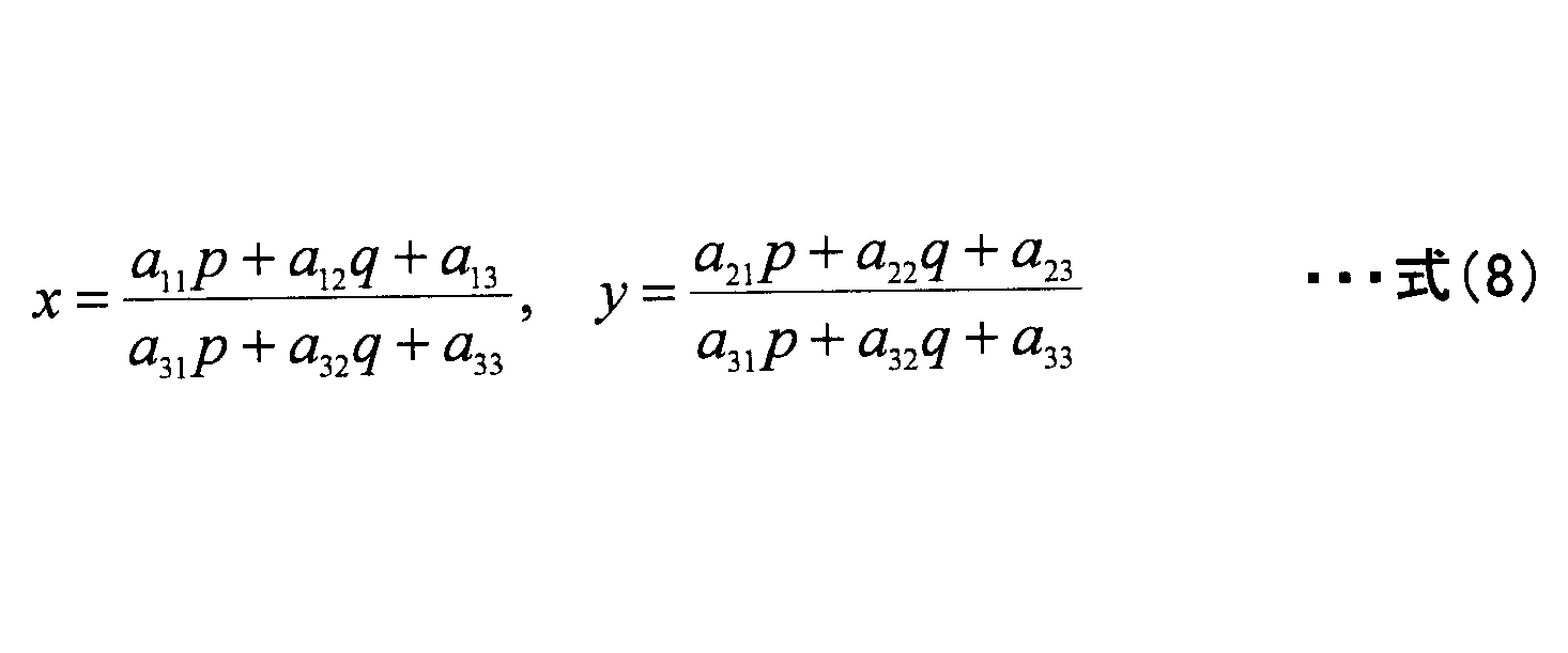
射影変換は、手のひらの形を3次元空間内の平面、撮影手段103の光学系を透視投影と見なしたときのモデルであり、手のひらが傾いている場合にも適用可能である。ただし、モデルパラメータの決定には、4点の対応が必要となる。
次に、補助情報として、輪郭を用いる場合について説明する。指つけねと異なり、輪郭を構成する点は繋がっているため、前回の輪郭と今回の輪郭の対応点は容易には求められない。解決策としては、例えば以下の2方法が考えられる。
・輪郭を形成する点から特徴的な点を選び出す方法
・輪郭を構成する点の時間変化をモデル化して、対応点を取らずに変換パラメータを定める方法
1つ目の特徴的な点の選びかたとしては、例えば、曲率の極大点(曲がり方が大きい点)を用いることが考えられる。追跡手段109は、代わりに、注目点と一定画素(例えば5画素)離れた2点を結んだ2線分のなす角度が180度から最も離れる数点を選択してもよい。特徴的な点を選び出した後は、指つけねと同様の方法で追跡を行うことができる。
対応付け手段111は、追跡して得られた補助情報と抽出された生体情報とを、ひとまとまりのデータにまとめる。生体情報が得られなかった画像については、対応付け手段111は、対応付けを行わない。図3に示す動画像の例に対して、対応付けられた結果を図10と図11とに示す。
認証装置20の記憶手段205は、利用者のIDと、補助情報と、生体情報としての静脈像とを対応付けて記憶する。記憶手段205は、典型的には以下の形式のデータベースとして認証装置20内に実現される。
次に、補助情報を用いて位置合わせを行う手法の例について説明する。ここでは、平行移動による位置合わせのみを行う場合を扱う。例えば、照合データの座標を基準とし、登録データの座標値の移動量を定めるものとする。
位置合わせ手段207は、初期化として、補助情報の座標値の総和を保持する変数を用意し、0に初期化する。初期化処理は、x 座標、y 座標別々に行う。
位置合わせ手段207は、登録データ、照合データそれぞれに対して、補助情報の座標値の総和を計算する。
位置合わせ手段207は、座標値の総和を、補助情報の点数で割って、重心位置を算出する。
位置合わせ手段207は、照合データ側の重心位置から登録データ側の重心位置を引くことで、移動量を算出する。
類似度算出手段209は、静脈像が2値画像として表現される場合、類似度を、例えば以下の方法で算出する。
類似度算出手段209は、注目画素を画像左上に設定する。一致した画素の個数を保持する変数(カウンタ)と、静脈像を形成する画素の個数を保持する変数とを用意し、それぞれ0に初期化する。
類似度算出手段209は、注目画素における、2枚の画像の画素の値を獲得して比較する。類似度算出手段209は、両者がともに静脈像を表していれば、一致個数のカウンタの値を1つ増加させる。どちらかが静脈像を表していれば静脈像のカウンタの値を1つ増加させる。
類似度算出手段209は、注目画素を1つ右に移動する。注目画素が右端の場合には、類似度算出手段209は、注目画素を1つ下の左端に移動する。注目画素が右下の場合には、類似度算出処理が終了する。
類似度算出手段209は、再度、画素値の比較を行う。
類似度算出手段209は、前画素での処理が終わると、一致個数のカウンタの値を静脈像のカウンタの値で割った値を類似度とする。
162/186≒0.871
図16に示す補助情報の追跡を行わない場合には,類似度算出結果は、次の通りである。
159/189≒0.841
これにより、補助情報の追跡により位置合わせがより正確になり、類似度が向上していることが分かる。
判定手段211は、類似度算出手段209で算出された類似度と、予め設定された閾値Thとを比較し、閾値Thよりも大きい場合には、本人あるいは登録者の1人と判定する。
次に、認証システム1の動作について説明する。まず、認証処理について説明する。図17は、実施例1における認証処理の一例を示すフローチャートである。図17に示すステップS101で、照射手段101は、手のひらがかざされたことを検知すると、手のひらに近赤外光を照射する。なお、生体情報を取得する体の部位は、手のひらを例に挙げるが、手のひらに限られない。
次に、実施例2における認証システムについて説明する。実施例1では、補助情報の一部分が追跡できることを前提としていた。しかし、利用者の手のかざし方が悪い場合には、補助情報の追跡ができなくなる可能性がある。そこで、実施例2では、補助情報が少しでも多く撮影されるように、利用者に対して誘導を行う。
図20は、実施例2における認証システム2の構成の一例を示すブロック図である。図20に示す構成において、図1に示す認証システム1の構成と同様のものは同じ符号を付す。以下、実施例1と異なる構成について主に説明する。
誘導手段303は、補助情報の追跡により、今後、撮影範囲に収まる補助情報と撮影範囲からはみだす補助情報を予測することができる。利用者の動きを大きく変更する誘導は利便性が良くないので、誘導手段303は、基本的には予測した移動先から一定範囲内で最も補助情報が残る方向に誘導する。
・距離情報を使う方式
・距離情報を使わない方式
まず、距離情報を使う方式を説明する。距離情報は、通常の撮影とは別に手のひらまでの距離を計測する手段を備えて取得する。一般的には、カメラ以外の距離計測装置を用いる方法とパターン光を投影する照明装置を備えてパターン光による撮影結果から距離を算出する方法が考えられる。開示の技術では、距離情報の取得方法は公知の技術のいずれでもよい。
誘導手段303は、初回の撮影で得られた距離情報を前回の距離情報とする。前回の距離情報をd1とする。
誘導手段303は、今回の撮影画像取得時の距離情報を入力する。今回の距離情報をd2とする。
誘導手段303は、前回の距離情報および今回の距離情報が生体情報の撮影可能範囲にあれば、前回および今回の画像を、生体情報を抽出可能と推定する。この場合には、誘導手段303は、撮影済なので利用者への誘導は行わない。
誘導手段303は、次回の撮影時の距離を、例えばd3=d2-(d1-d2)で推定する。d3は、推定された次回撮影時の距離情報である。
誘導手段303は、d3が生体情報の撮影可能範囲にあれば、次回の撮影で抽出可能と推定する。d3が撮影可能範囲を下回っていれば。利用者の動きが速すぎるので減速するように誘導し、次回の撮影で抽出可能と推定する。d3が撮影可能範囲を上回っていれば、前回の距離情報を今回の距離情報で置き換えて再び距離情報の入力を行う。
図23の誘導後の生体情報の例と図13に示す登録データ例とに対して、類似度算出手段209は、実施例1と同一の類似度算出方法を用いた場合の類似度を算出する。類似度算出手段209は、次の類似度を得る。
165/183≒0.902
誘導手段303によって、位置合わせがより正確になり、類似度が向上していることが分かる。判定手段211で閾値Thが0.85 とする場合には本人と判定されるが、他人受入率をより小さくするため、閾値Thを0.90に上げた場合でも、同様に本人と判定される。
次に、実施例2における認証システム2の動作について説明する。図24は、実施例2における認証処理の一例を示すフローチャートである。図24に示すステップS401~S406の処理は、図17に示すステップS101~S106の処理と同様であるため、その説明を省略する。
上記各実施例の変形例として、距離情報が利用可能な場合には、生体情報抽出手段107に距離情報を渡し、距離値が予め設定された範囲にある場合にのみ抽出処理を行うようにすることも可能である。これにより、生体情報抽出手段107が不適切な画像から誤って疑似の生体情報を抽出する危険性を下げることができる。
次に、実施例3における情報処理装置について説明する。実施例3では、実施例1,2で説明した処理を、PCやサーバなどの情報処理装置で行う。
図25は、実施例3における情報処理装置30の構成の一例を示すブロック図である。図25に示す情報処理装置30は、制御部401、主記憶部403、補助記憶部405、通信部407、記録媒体I/F部409、入力部411、表示部413、及びカメラ415を少なくとも有する。各部は、バスを介して相互にデータ送受信可能に接続されている。
以上、生体情報処理装置、生体情報処理方法及びプログラムを各実施例により説明したが、上記各実施例に限定されるものではなく、特許請求の範囲に記載された範囲内において、種々の変形及び変更が可能である。また、前述した各実施例の構成要素を全部又は複数を組み合わせることも可能である。
Claims (7)
- 撮影手段により撮影された複数の画像から、生体情報と共に撮影される体の一部を示す補助情報を抽出する補助情報抽出手段と、
前記補助情報を時間方向に追跡する追跡手段と、
前記複数の画像のうちの少なくとも1つの画像から、前記生体情報を抽出する生体情報抽出手段と、
追跡された前記補助情報と、抽出された前記生体情報との位置関係を対応付ける対応付け手段と、
対応付けられた前記補助情報と前記生体情報とを出力する出力手段と
を備える生体情報処理装置。 - 前記追跡手段は、
補助情報の時間変化のモデルを用いて、撮影範囲外に位置する補助情報を推定値で置き換える請求項1記載の生体情報処理装置。 - 前記生体情報は、手から抽出される生体情報であり、
前記補助情報は、手の輪郭の情報又は指のつけねの情報である請求項1又は2記載の生体情報処理装置。 - 前記補助情報の時間変化に基づいて該補助情報の位置を予測し、予測された補助情報が撮影範囲外であれば、撮影範囲内に収まる位置に利用者を誘導する誘導手段をさらに備える請求項1乃至3いずれか一項に記載の生体情報処理装置。
- 前記追跡手段は、
追跡対象画像から抽出された第1の補助情報と、前記追跡対象画像の直前の画像から抽出された第2の補助情報とで追跡を行って、対応が取れた補助情報の数に応じて、前記モデルを変更する請求項2記載の生体情報処理装置。 - 撮影手段により撮影された複数の画像から、生体情報と共に撮影される体の一部を示す補助情報を抽出し、
前記補助情報を時間方向に追跡し、
前記複数の画像のうちの少なくとも1つの画像から、前記生体情報を抽出し、
追跡された前記補助情報と、抽出された前記生体情報との位置関係を対応付け、
対応付けられた前記補助情報と前記生体情報とを出力する処理を
コンピュータが実行する生体情報処理方法。 - 撮影手段により撮影された複数の画像から、生体情報と共に撮影される体の一部を示す補助情報を抽出し、
前記補助情報を時間方向に追跡し、
前記複数の画像のうちの少なくとも1つの画像から、前記生体情報を抽出し、
追跡された前記補助情報と、抽出された前記生体情報との位置関係を対応付け、
対応付けられた前記補助情報と前記生体情報とを出力する処理を
コンピュータに実行させるプログラム。
Priority Applications (4)
| Application Number | Priority Date | Filing Date | Title |
|---|---|---|---|
| PCT/JP2012/063095 WO2013175579A1 (ja) | 2012-05-22 | 2012-05-22 | 生体情報処理装置、生体情報処理方法及びプログラム |
| JP2014516560A JP5949912B2 (ja) | 2012-05-22 | 2012-05-22 | 生体情報処理装置、生体情報処理方法及びプログラム |
| EP12877423.9A EP2854097B1 (en) | 2012-05-22 | 2012-05-22 | Bio-information processing device, bio-information processing method, and program |
| US14/538,075 US9418275B2 (en) | 2012-05-22 | 2014-11-11 | Biometric information processing for providing increased authentication precision by guiding a user to place auxiliary information within an imaging range |
Applications Claiming Priority (1)
| Application Number | Priority Date | Filing Date | Title |
|---|---|---|---|
| PCT/JP2012/063095 WO2013175579A1 (ja) | 2012-05-22 | 2012-05-22 | 生体情報処理装置、生体情報処理方法及びプログラム |
Related Child Applications (1)
| Application Number | Title | Priority Date | Filing Date |
|---|---|---|---|
| US14/538,075 Continuation US9418275B2 (en) | 2012-05-22 | 2014-11-11 | Biometric information processing for providing increased authentication precision by guiding a user to place auxiliary information within an imaging range |
Publications (1)
| Publication Number | Publication Date |
|---|---|
| WO2013175579A1 true WO2013175579A1 (ja) | 2013-11-28 |
Family
ID=49623310
Family Applications (1)
| Application Number | Title | Priority Date | Filing Date |
|---|---|---|---|
| PCT/JP2012/063095 Ceased WO2013175579A1 (ja) | 2012-05-22 | 2012-05-22 | 生体情報処理装置、生体情報処理方法及びプログラム |
Country Status (4)
| Country | Link |
|---|---|
| US (1) | US9418275B2 (ja) |
| EP (1) | EP2854097B1 (ja) |
| JP (1) | JP5949912B2 (ja) |
| WO (1) | WO2013175579A1 (ja) |
Cited By (1)
| Publication number | Priority date | Publication date | Assignee | Title |
|---|---|---|---|---|
| JP2020102014A (ja) * | 2018-12-21 | 2020-07-02 | 富士通株式会社 | 生体認証装置、生体認証プログラム、及び生体認証方法 |
Families Citing this family (7)
| Publication number | Priority date | Publication date | Assignee | Title |
|---|---|---|---|---|
| TW201336319A (zh) * | 2012-02-23 | 2013-09-01 | Novatek Microelectronics Corp | 消除影像色彩偏差的方法與裝置 |
| US9749317B2 (en) | 2015-08-28 | 2017-08-29 | At&T Intellectual Property I, L.P. | Nullifying biometrics |
| CH713061B1 (de) * | 2016-10-19 | 2021-03-31 | Smart Secure Id Ag | System und Verfahren zur berührungslosen biometrischen Authentifizierung. |
| US10255416B2 (en) * | 2017-01-25 | 2019-04-09 | Ca, Inc. | Secure biometric authentication with client-side feature extraction |
| CN109389015A (zh) * | 2017-08-10 | 2019-02-26 | 丽宝大数据股份有限公司 | 脸部相似度评估方法与电子装置 |
| KR20190046063A (ko) * | 2017-10-25 | 2019-05-07 | 현대자동차주식회사 | 사용자 인증 시스템, 사용자 인증 방법 및 서버 |
| DE102021111422A1 (de) * | 2021-05-04 | 2022-11-10 | IDloop GmbH | Vorrichtung und Verfahren zur kontaktlosen Aufnahme von Finger- und Handabdrücken |
Citations (8)
| Publication number | Priority date | Publication date | Assignee | Title |
|---|---|---|---|---|
| JPH08241480A (ja) * | 1995-03-07 | 1996-09-17 | Matsushita Electric Ind Co Ltd | 分散型監視装置 |
| JP2003067750A (ja) | 2001-08-27 | 2003-03-07 | Mitsubishi Electric Corp | 指紋照合装置 |
| JP2004021884A (ja) | 2002-06-20 | 2004-01-22 | Toshiba Corp | マルチタスクプロセッサおよび移動通信端末 |
| JP2004102993A (ja) | 2003-08-11 | 2004-04-02 | Hitachi Ltd | 個人認証装置及び方法 |
| JP2005227957A (ja) | 2004-02-12 | 2005-08-25 | Mitsubishi Electric Corp | 最適顔画像記録装置及び最適顔画像記録方法 |
| JP2006107399A (ja) * | 2004-10-08 | 2006-04-20 | Fujitsu Ltd | 生体認証方法及び生体認証装置 |
| JP2007249587A (ja) * | 2006-03-15 | 2007-09-27 | Omron Corp | 認証装置、認証方法、認証プログラム、これを記録したコンピュータ読み取り可能な記録媒体 |
| JP2011210030A (ja) * | 2010-03-30 | 2011-10-20 | Panasonic Corp | 顔認識装置及び顔認識方法 |
Family Cites Families (8)
| Publication number | Priority date | Publication date | Assignee | Title |
|---|---|---|---|---|
| JP3558025B2 (ja) | 2000-09-06 | 2004-08-25 | 株式会社日立製作所 | 個人認証装置及び方法 |
| US8190239B2 (en) | 2002-09-03 | 2012-05-29 | Fujitsu Limited | Individual identification device |
| JP3810782B2 (ja) | 2002-09-03 | 2006-08-16 | 富士通株式会社 | 個人認識装置 |
| JP4680158B2 (ja) * | 2006-09-13 | 2011-05-11 | 株式会社日立製作所 | 生体認証装置 |
| JP4786483B2 (ja) * | 2006-09-14 | 2011-10-05 | 富士通株式会社 | 生体認証装置の生体誘導制御方法及び生体認証装置 |
| JP4541427B2 (ja) * | 2008-03-25 | 2010-09-08 | 富士通株式会社 | 生体認証装置、生体情報登録装置および生体認証方法 |
| JP5065965B2 (ja) * | 2008-03-31 | 2012-11-07 | 富士通株式会社 | 非接触型生体認証装置の生体誘導制御方法及び非接触型生体認証装置 |
| EP2371283B1 (en) * | 2008-12-17 | 2017-03-29 | Fujitsu Limited | Biometric authentication device and biometric authentication method |
-
2012
- 2012-05-22 WO PCT/JP2012/063095 patent/WO2013175579A1/ja not_active Ceased
- 2012-05-22 EP EP12877423.9A patent/EP2854097B1/en not_active Not-in-force
- 2012-05-22 JP JP2014516560A patent/JP5949912B2/ja not_active Expired - Fee Related
-
2014
- 2014-11-11 US US14/538,075 patent/US9418275B2/en not_active Expired - Fee Related
Patent Citations (8)
| Publication number | Priority date | Publication date | Assignee | Title |
|---|---|---|---|---|
| JPH08241480A (ja) * | 1995-03-07 | 1996-09-17 | Matsushita Electric Ind Co Ltd | 分散型監視装置 |
| JP2003067750A (ja) | 2001-08-27 | 2003-03-07 | Mitsubishi Electric Corp | 指紋照合装置 |
| JP2004021884A (ja) | 2002-06-20 | 2004-01-22 | Toshiba Corp | マルチタスクプロセッサおよび移動通信端末 |
| JP2004102993A (ja) | 2003-08-11 | 2004-04-02 | Hitachi Ltd | 個人認証装置及び方法 |
| JP2005227957A (ja) | 2004-02-12 | 2005-08-25 | Mitsubishi Electric Corp | 最適顔画像記録装置及び最適顔画像記録方法 |
| JP2006107399A (ja) * | 2004-10-08 | 2006-04-20 | Fujitsu Ltd | 生体認証方法及び生体認証装置 |
| JP2007249587A (ja) * | 2006-03-15 | 2007-09-27 | Omron Corp | 認証装置、認証方法、認証プログラム、これを記録したコンピュータ読み取り可能な記録媒体 |
| JP2011210030A (ja) * | 2010-03-30 | 2011-10-20 | Panasonic Corp | 顔認識装置及び顔認識方法 |
Non-Patent Citations (1)
| Title |
|---|
| See also references of EP2854097A4 |
Cited By (1)
| Publication number | Priority date | Publication date | Assignee | Title |
|---|---|---|---|---|
| JP2020102014A (ja) * | 2018-12-21 | 2020-07-02 | 富士通株式会社 | 生体認証装置、生体認証プログラム、及び生体認証方法 |
Also Published As
| Publication number | Publication date |
|---|---|
| US9418275B2 (en) | 2016-08-16 |
| EP2854097B1 (en) | 2017-09-27 |
| JPWO2013175579A1 (ja) | 2016-01-12 |
| EP2854097A4 (en) | 2016-02-24 |
| EP2854097A1 (en) | 2015-04-01 |
| JP5949912B2 (ja) | 2016-07-13 |
| US20150063664A1 (en) | 2015-03-05 |
Similar Documents
| Publication | Publication Date | Title |
|---|---|---|
| JP5949912B2 (ja) | 生体情報処理装置、生体情報処理方法及びプログラム | |
| JP7242528B2 (ja) | モバイルデバイスを用いてキャプチャした画像を使用する、指紋によるユーザ認証を実施するためのシステムおよび方法 | |
| CN107949863B (zh) | 使用生物体信息的认证装置以及认证方法 | |
| US20200110921A1 (en) | Systems and methods for performing fingerprint based user authentication using imagery captured using mobile devices | |
| US12217548B2 (en) | Authentication device, authentication method, and recording medium | |
| JP4770936B2 (ja) | 静脈認証装置およびテンプレート登録方法 | |
| JP2000306095A (ja) | 画像照合・検索システム | |
| JP6532642B2 (ja) | 生体情報認証装置および生体情報処理方法 | |
| KR20110063679A (ko) | 정맥 패턴 인식 기반 생체인증 시스템 및 그 방법 | |
| EP2781185B1 (en) | Biometric information input apparatus, biometric information input program and biometric information input method | |
| WO2013161077A1 (ja) | 生体認証装置、生体認証プログラム及び生体認証方法 | |
| JP6265592B2 (ja) | 顔特徴抽出装置および顔認証システム | |
| JP5170094B2 (ja) | なりすまし検知システム、なりすまし検知方法およびなりすまし検知用プログラム | |
| JP2013205931A (ja) | 生体情報取得装置、生体情報取得方法、生体情報取得制御プログラム | |
| JP7269897B2 (ja) | データ登録装置、生体認証装置、およびデータ登録プログラム | |
| CN115577337A (zh) | 一种基于人脸识别的智能安防设备控制方法和系统 | |
| US8787625B2 (en) | Use of relatively permanent pigmented or vascular skin mark patterns in images for personal identification | |
| JP2010240215A (ja) | 静脈深度判定装置、静脈深度判定方法およびプログラム | |
| JP2008210328A (ja) | 眼底画像認証装置及び眼底画像認証プログラム | |
| WO2012029150A1 (ja) | 生体認証システム、生体認証方法、及びプログラム | |
| CN108875472A (zh) | 图像采集装置及基于该图像采集装置的人脸身份验证方法 | |
| WO2023007586A1 (ja) | 判定方法、判定プログラム、及び情報処理装置 | |
| JP2017162301A (ja) | 生体認証装置、生体認証方法および生体認証プログラム |
Legal Events
| Date | Code | Title | Description |
|---|---|---|---|
| 121 | Ep: the epo has been informed by wipo that ep was designated in this application |
Ref document number: 12877423 Country of ref document: EP Kind code of ref document: A1 |
|
| ENP | Entry into the national phase |
Ref document number: 2014516560 Country of ref document: JP Kind code of ref document: A |
|
| REEP | Request for entry into the european phase |
Ref document number: 2012877423 Country of ref document: EP |
|
| WWE | Wipo information: entry into national phase |
Ref document number: 2012877423 Country of ref document: EP |
|
| NENP | Non-entry into the national phase |
Ref country code: DE |