WO2013175624A1 - 電動モータ - Google Patents
電動モータ Download PDFInfo
- Publication number
- WO2013175624A1 WO2013175624A1 PCT/JP2012/063475 JP2012063475W WO2013175624A1 WO 2013175624 A1 WO2013175624 A1 WO 2013175624A1 JP 2012063475 W JP2012063475 W JP 2012063475W WO 2013175624 A1 WO2013175624 A1 WO 2013175624A1
- Authority
- WO
- WIPO (PCT)
- Prior art keywords
- winding
- phase
- slot
- coil
- teeth
- Prior art date
- Legal status (The legal status is an assumption and is not a legal conclusion. Google has not performed a legal analysis and makes no representation as to the accuracy of the status listed.)
- Ceased
Links
Images







Classifications
-
- H—ELECTRICITY
- H02—GENERATION; CONVERSION OR DISTRIBUTION OF ELECTRIC POWER
- H02K—DYNAMO-ELECTRIC MACHINES
- H02K1/00—Details of the magnetic circuit
- H02K1/06—Details of the magnetic circuit characterised by the shape, form or construction
- H02K1/12—Stationary parts of the magnetic circuit
- H02K1/17—Stator cores with permanent magnets
-
- H—ELECTRICITY
- H02—GENERATION; CONVERSION OR DISTRIBUTION OF ELECTRIC POWER
- H02K—DYNAMO-ELECTRIC MACHINES
- H02K1/00—Details of the magnetic circuit
- H02K1/06—Details of the magnetic circuit characterised by the shape, form or construction
- H02K1/22—Rotating parts of the magnetic circuit
- H02K1/26—Rotor cores with slots for windings
- H02K1/265—Shape, form or location of the slots
-
- H—ELECTRICITY
- H02—GENERATION; CONVERSION OR DISTRIBUTION OF ELECTRIC POWER
- H02K—DYNAMO-ELECTRIC MACHINES
- H02K11/00—Structural association of dynamo-electric machines with electric components or with devices for shielding, monitoring or protection
- H02K11/20—Structural association of dynamo-electric machines with electric components or with devices for shielding, monitoring or protection for measuring, monitoring, testing, protecting or switching
- H02K11/25—Devices for sensing temperature, or actuated thereby
-
- H—ELECTRICITY
- H02—GENERATION; CONVERSION OR DISTRIBUTION OF ELECTRIC POWER
- H02K—DYNAMO-ELECTRIC MACHINES
- H02K13/00—Structural associations of current collectors with motors or generators, e.g. brush mounting plates or connections to windings; Disposition of current collectors in motors or generators; Arrangements for improving commutation
- H02K13/006—Structural associations of commutators
-
- H—ELECTRICITY
- H02—GENERATION; CONVERSION OR DISTRIBUTION OF ELECTRIC POWER
- H02K—DYNAMO-ELECTRIC MACHINES
- H02K23/00—DC commutator motors or generators having mechanical commutator; Universal AC/DC commutator motors
- H02K23/02—DC commutator motors or generators having mechanical commutator; Universal AC/DC commutator motors characterised by arrangement for exciting
- H02K23/04—DC commutator motors or generators having mechanical commutator; Universal AC/DC commutator motors characterised by arrangement for exciting having permanent magnet excitation
-
- H—ELECTRICITY
- H02—GENERATION; CONVERSION OR DISTRIBUTION OF ELECTRIC POWER
- H02K—DYNAMO-ELECTRIC MACHINES
- H02K23/00—DC commutator motors or generators having mechanical commutator; Universal AC/DC commutator motors
- H02K23/26—DC commutator motors or generators having mechanical commutator; Universal AC/DC commutator motors characterised by the armature windings
- H02K23/32—DC commutator motors or generators having mechanical commutator; Universal AC/DC commutator motors characterised by the armature windings having wave or undulating windings
-
- H—ELECTRICITY
- H02—GENERATION; CONVERSION OR DISTRIBUTION OF ELECTRIC POWER
- H02K—DYNAMO-ELECTRIC MACHINES
- H02K3/00—Details of windings
- H02K3/04—Windings characterised by the conductor shape, form or construction, e.g. with bar conductors
- H02K3/28—Layout of windings or of connections between windings
-
- H—ELECTRICITY
- H02—GENERATION; CONVERSION OR DISTRIBUTION OF ELECTRIC POWER
- H02K—DYNAMO-ELECTRIC MACHINES
- H02K7/00—Arrangements for handling mechanical energy structurally associated with dynamo-electric machines, e.g. structural association with mechanical driving motors or auxiliary dynamo-electric machines
- H02K7/10—Structural association with clutches, brakes, gears, pulleys or mechanical starters
- H02K7/116—Structural association with clutches, brakes, gears, pulleys or mechanical starters with gears
- H02K7/1163—Structural association with clutches, brakes, gears, pulleys or mechanical starters with gears where at least two gears have non-parallel axes without having orbital motion
- H02K7/1166—Structural association with clutches, brakes, gears, pulleys or mechanical starters with gears where at least two gears have non-parallel axes without having orbital motion comprising worm and worm-wheel
-
- H—ELECTRICITY
- H02—GENERATION; CONVERSION OR DISTRIBUTION OF ELECTRIC POWER
- H02K—DYNAMO-ELECTRIC MACHINES
- H02K11/00—Structural association of dynamo-electric machines with electric components or with devices for shielding, monitoring or protection
- H02K11/02—Structural association of dynamo-electric machines with electric components or with devices for shielding, monitoring or protection for suppression of electromagnetic interference
- H02K11/026—Suppressors associated with brushes, brush holders or their supports
-
- H—ELECTRICITY
- H02—GENERATION; CONVERSION OR DISTRIBUTION OF ELECTRIC POWER
- H02K—DYNAMO-ELECTRIC MACHINES
- H02K5/00—Casings; Enclosures; Supports
- H02K5/04—Casings or enclosures characterised by the shape, form or construction thereof
- H02K5/14—Means for supporting or protecting brushes or brush holders
- H02K5/143—Means for supporting or protecting brushes or brush holders for cooperation with commutators
- H02K5/148—Slidably supported brushes
Definitions
- the present invention relates to an electric motor mounted on a vehicle, for example.
- an electric motor for example, there is an electric motor with a brush in which a plurality of permanent magnets are arranged on the inner peripheral surface of a bottomed cylindrical yoke and an armature is rotatably provided radially inward of the permanent magnet.
- the armature includes an armature core that is externally fixed to a rotating shaft, and a commutator in which a plurality of segments are disposed.
- the armature core is provided with a plurality of teeth extending radially outward, and a plurality of axially long slots are formed between the teeth. Windings are inserted through these slots, and windings are wound around each tooth by a concentrated winding method or a distributed winding method.
- the winding is in conduction with the commutator segment.
- Each segment is in sliding contact with a brush for supplying power, and current is supplied to the winding through this brush.
- a current is supplied to the winding, a magnetic field is formed, and the armature is rotated by a magnetic attractive force or a repulsive force generated between the magnetic field and the permanent magnet.
- an electric motor having a substantially bottomed cylindrical yoke and an end bracket formed with a connector portion and fixed so as to close the yoke, the thermistor and anti-noise element (this application) (Refer to Patent Document 2, for example).
- a coil wound after a coil wound earlier is wound outward in the radial direction. It will be. That is, the coil wound in the subsequent process is arranged on the opening side in the slot.
- One slot accommodates the first wound winding and the second wound winding, and one slot is the last wound winding and the second winding wound last. Will be housed. For this reason, if all the slots are formed in the same shape, useless space is generated in each slot, and the position and state of the coil become unstable. As a result, the armature is unbalanced in rotation.
- the electric motor of Patent Document 1 has ring-shaped or tile-shaped permanent magnets arranged on the inner peripheral surface of a cylindrical yoke, the size of the outer shape of the electric motor is mainly the processing thickness of the permanent magnet. It is restricted by the size. Therefore, there is a limit to further downsizing while maintaining the performance of the electric motor.
- the end bracket of Patent Document 2 is formed in a substantially circular shape in a plan view in the axial direction, and a long plate-like thermistor is disposed on the outer peripheral side.
- This thermistor gets in the way, making it difficult to reduce the size of the end bracket.
- the yoke itself is also difficult to reduce in size, and as a result, the entire electric motor may be increased in size.
- the connector portion is formed to protrude from the outer peripheral wall of the end bracket.
- the noise prevention element is arrange
- Patent Document 3 is excellent in that it can prevent the rotation imbalance of the armature, but the slot area itself is narrowed, so it is difficult to increase the coil space factor. There is sex. As a result, there is a possibility that it is difficult to reduce the size and weight of the electric motor.
- the present invention has been made in view of the above-described circumstances, and an object thereof is to provide an electric motor that can be reduced in size without depending on the thickness of a permanent magnet. It is another object of the present invention to provide an electric motor that can reduce the manufacturing time by shortening the total time of winding the coil on the armature and the connecting time of the connecting line to the segment. It is another object of the present invention to provide an electric motor capable of improving the coil space factor while preventing useless space in the slot.
- the electric motor includes a yoke having a cylindrical portion, two pairs of permanent magnets arranged to face the inner peripheral surface of the cylindrical portion, and radially inward of the permanent magnet.
- An armature rotatably supported, and at least one pair of first flat portions opposed to each other in the radial direction is formed in the cylindrical portion, and the permanent magnet is disposed at a position avoiding the first flat portions. .
- the pair of first flat portions opposed to each other in the radial direction is formed on the cylindrical portion.
- the electric motor includes two brushes for supplying power to the armature, and the two brushes have a mechanical angle of 90 ° in the circumferential direction. And a thermal protection element for interrupting power supply to the armature when overheated, on the opposite side of the two brushes across the rotation axis of the armature.
- a core body that is externally fitted and fixed to the rotary shaft, and a radially outward projecting from the core body.
- a plurality of core plates each having 10 teeth, and an armature core in which a winding is wound between two adjacent teeth in the circumferential direction.
- the teeth are adjacent to each other in the circumferential direction.
- the tooth group is composed of two deformed teeth, and the two tooth groups are arranged symmetrically with respect to each other about the rotation axis, and the five deformed teeth extend along the radial direction.
- a first deformed tooth formed such that a tip thereof tilts toward a side opposite to a winding direction of the winding with respect to the virtual reference tooth, and a circumferential direction on the winding direction side of the first deformed tooth.
- Along 4 is formed, and is configured by second deformed teeth formed so that the tip thereof tilts toward the winding direction with respect to the virtual reference teeth, and the second deformed teeth and the second deformed teeth
- the first deformed slot formed between the first deformed teeth adjacent on the winding direction side, the first deformed teeth, and the first deformed teeth are adjacent on the winding direction side.
- a second deformed slot formed between the second deformed teeth and three third deformed slots formed between the second deformed teeth adjacent to each other in the circumferential direction in this order in the winding direction. It is formed towards.
- the rotating shaft includes a commutator provided adjacent to the armature core, and is adjacent to each tooth.
- the winding is wound in a distributed winding manner so as to straddle the two teeth, and the U1 phase, V1 phase, W1 phase, X1 phase, Y1 phase, U2 phase, V2 phase, W2 phase, X2 phase, Y2 phase in the circumferential direction
- a coil having a five-phase structure is formed in order, and the commutator has a total of ten segments in the circumferential direction so that two segments of the same potential corresponding to each phase are arranged opposite to each other around the rotation axis.
- the same potential segments are short-circuited by the windings to form a 4-pole 10-slot 10 segment, and the windings are connected to two segments corresponding to the U1-phase coil.
- the winding is wound between the first deformed slot corresponding to the U1 phase and the third deformed slot disposed behind the first deformed slot in the winding direction.
- the second variant slot and the second variant slot are arranged behind the second variant slot in the winding direction.
- the winding is wound between the third deformed slot, and after connecting the winding to two segments corresponding to the coil of the W1 phase, corresponding to the W1 phase, Of the three third variant slots, the winding is wound around two third variant slots existing on both sides of the middle third variant slot, and then the X1 phase coil is wound on the coil. The windings in the corresponding two segments Subsequently, the winding is wound between the first deformed slot corresponding to the X1 phase and the third deformed slot disposed behind the first deformed slot in the winding direction. Then, after the winding is connected to two segments corresponding to the Y1 phase coil, the second variant slot and the winding direction of the second variant slot correspond to the Y1 phase.
- the winding is wound between the third deformed slot arranged at the rear, and the U1, V1, W1, X1, and Y1 phase coils are formed at the same time. After the winding is connected to two segments corresponding to the U2-phase coil, the winding corresponds to the U2-phase, and is disposed behind the first variant slot and the first variant slot in the winding direction.
- the third variant slot Winding a winding, and then connecting the winding to two segments corresponding to the V2 phase coil, then corresponding to the V2 phase and the second variant slot, and the second variant slot After winding the winding between the third deformed slot arranged at the rear of the winding direction and connecting the winding to two segments corresponding to the W2-phase coil
- the winding is wound around two third variant slots corresponding to the W2 phase and existing on both sides of the third variant slot among the three third variant slots, Thereafter, the winding is connected to two segments corresponding to the X2-phase coil, and then corresponds to the X2-phase, and is disposed behind the first variant slot and the first variant slot in the winding direction.
- the third variant slot being And then connecting the winding to two segments corresponding to the Y2-phase coil, and then corresponding to the Y2-phase and the second variant slot,
- the winding is wound between the third variant slot arranged behind the irregular slot in the winding direction, and the positional relationship between a predetermined segment and a predetermined tooth over which the winding is wound Are in a positional relationship facing each other about the rotation axis.
- the electric motor by forming the first flat portion on the cylindrical portion of the yoke, the electric motor can be made smaller than when the cylindrical portion is formed in a cylindrical shape. Further, by arranging the permanent magnet at a position avoiding the first flat portion, the electric motor can be reduced in size without depending on the thickness of the permanent magnet.
- the electric motor described above it is possible to tilt the teeth in accordance with the position of the coil wound around each irregularly shaped slot, and to prevent a useless space from being generated in the irregularly shaped slot. For this reason, the space factor of the coil can be improved, and the coil can be distributed in a well-balanced manner in each irregularly shaped slot. As a result, the electric motor can be reduced in size and weight.
- the armature core itself is formed in a different shape, the armature core itself has a point-symmetric shape around the rotation axis, so that it is possible to more reliably prevent the armature from causing rotational unbalance.
- a so-called double flyer method in which distributed winding is performed at two points simultaneously in a point-symmetrical manner with respect to the rotation axis can be adopted as a method of winding the winding around the armature core. For this reason, the total time of the winding time of the coil to an armature and the connection time of the connection line to a segment can be shortened, and manufacturing cost can be reduced.
- the winding under the neck of the commutator is applied to the rotation axis. Can be routed to. For this reason, it can prevent that the winding under the neck of a commutator loosens toward the radial direction outer side, and can reduce the winding thickness by winding.
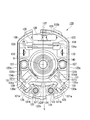
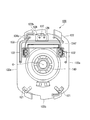
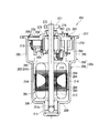
- FIG. 2 is a cross-sectional view taken along line AA in FIG. It is a cross-sectional view of the electric motor in the modification of 1st Embodiment. It is explanatory drawing of the motor apparatus with a speed-reduction mechanism in the modification of 1st Embodiment. It is a cross-sectional view of the electric motor in 2nd Embodiment. It is explanatory drawing of the motor apparatus with a deceleration mechanism in 2nd Embodiment. It is a transverse cross section of the electric motor in the modification of a 2nd embodiment.
- FIG. 10 is a cross-sectional view taken along the line BB in FIG. 9. It is a perspective view of the brush holder unit in 3rd Embodiment. It is a top view of the brush holder unit in 3rd Embodiment. It is a bottom view of the brush holder unit in 3rd Embodiment. It is explanatory drawing of the electric circuit in 3rd Embodiment. It is a longitudinal cross-sectional view of the electric motor in 4th Embodiment.
- the motor device 1 with a speed reduction mechanism using the electric motor 2 shown in FIGS. 1 and 2 is used for driving at least one of a vehicle power window, a sunroof, an electric seat, and a wiper device, for example.
- the armature 6 is rotatably provided in the cylindrical portion 53 of the yoke 5, and the brush holder 22 is fitted and fixed in a brush holder storage portion 90 formed on the opening 53 b side of the cylindrical portion 53.
- the yoke 5 is a bottomed cylindrical member made of a metal such as iron, and is molded by, for example, deep drawing or the like.
- the cylindrical portion 53 occupying most of the yoke 5 connects the pair of first flat portions 61 and the pair of first flat portions 61 facing each other in the radial direction across the central axis O when viewed from the axial direction.
- the separation distance of the first flat portion 61 is set to be slightly larger than the diameter of the armature 6 disposed in the cylindrical portion 53.
- the arc-shaped portion 63 connects the circumferential ends of the first flat portions 61 facing each other.
- the center of curvature of the arc-shaped portion 63 is set to be the same as the rotation center of the armature 6 when viewed from the axial direction. Further, the radius of curvature of the inner peripheral surface 63 a of the arc-shaped portion 63 is set to be slightly larger than the radius of the armature 6.
- a permanent magnet 7 is provided on the inner peripheral surface 53 a of the cylindrical portion 53 of the yoke 5.
- a rare earth magnet such as a neodymium sintered magnet or neodymium bonded magnet, a ferrite magnet, or the like is used.
- the permanent magnet 7 is formed in a substantially arc shape when viewed from the axial direction, and has an inner peripheral surface 7a and an outer peripheral surface 7b that are parallel to each other, and a side surface 7c that is disposed therebetween.
- the radius of curvature of the inner peripheral surface 7a of the permanent magnet 7 is set to be slightly larger than the radius of the armature 6. Further, the radius of curvature of the outer peripheral surface 7 b of the permanent magnet 7 is set to be substantially the same as the radius of curvature of the inner peripheral surface 63 a of the arc-shaped portion 63 formed in the cylindrical portion 53.
- the axial length of the permanent magnet 7 is set to be substantially the same as the axial length of the cylindrical portion 53 of the yoke 5.
- the permanent magnet 7 formed as described above are fixed to the inner peripheral surface 63a of the arc-shaped portion 63 with the outer peripheral surface 7b facing the arc-shaped portion 63 side of the cylindrical portion 53.
- the permanent magnet 7 is affixed to the inner peripheral surface 63a of the arc-shaped portion 63 with an adhesive or the like.
- the four permanent magnets 7 are arranged so that the N-pole and S-pole magnetic poles alternate along the circumferential direction.
- the four permanent magnets 7 are arranged so that the N-pole and S-pole magnetic poles face each other. Further, the pitch angle between the adjacent permanent magnets 7 is set to be about 90 °. That is, the electric motor 2 forms a two-pole pair motor.
- the width of the opposed first flat portion 61 is L1
- the width of the opposed arc-shaped portion 63 is R1
- the width L1 of the first flat portion 61 and the width R1 of the arc-shaped portion 63 are: L1 ⁇ R1 (1) It is set to satisfy.
- the pair of first flat portions 61 of the cylindrical portion 53 are provided so as to be flush with a pair of flat walls 91 formed in a brush holder storage portion 90 described later. Yes. Further, the first flat portion 61 of the cylindrical portion 53 is arranged in the short direction (left and right direction in FIG. 2) of the brush holder 22 described later.
- a boss 19 that protrudes outward along the central axis O is formed in the approximate center of the bottom wall 51 of the yoke 5.
- a bearing 18 made of an annular metal or the like is press-fitted and fixed to the inner peripheral surface of the boss 19.
- One end side (the right side in FIG. 1) of the rotary shaft 3 is pivotally supported by a boss 19 of the yoke 5 via a bearing 18.
- a thrust plate 34 is provided at the bottom of the boss 19.
- the thrust plate 34 receives a thrust load of the rotary shaft 3 through the steel balls 35.
- the steel ball 35 reduces the sliding resistance between the rotating shaft 3 and the thrust plate 34 and absorbs the misalignment of the rotating shaft 3.
- a brush holder housing 90 is integrally formed in the cylindrical portion 53 of the yoke 5 on the opening 53b side (left side in FIG. 1).
- the peripheral wall 90a of the brush holder storage part 90 is for storing the brush holder 22 described later.
- the peripheral wall 90a of the brush holder housing 90 is formed in a substantially oval shape when viewed from the axial direction, and one radial direction (vertical direction in FIG. 2) is the longitudinal direction, and the other radial direction (FIG. 2).
- the brush holder housing 90 includes a pair of flat walls 91 facing in the short direction and a pair of arcuate walls 92 connecting the circumferential ends of the flat wall 91 in the longitudinal direction.
- a step wall 93 is provided between the arc-shaped wall 92 of the brush holder housing portion 90 and the arc-shaped portion 63 of the tube portion 53.
- the arc-shaped portion 63 of the cylindrical portion 53 and the arc-shaped wall 92 of the brush holder storage portion 90 are continuously formed integrally.
- the pair of flat walls 91 are provided so as to be flush with the pair of first flat portions 61 formed in the cylindrical portion 53.
- the width L1 of the first flat portion 61 and the width R1 of the arc-shaped portion 63 satisfy the expression (1). Therefore, the pair of first flat portions 61 having a narrower width L1 out of the pair of first flat portions 61 and the pair of arc-shaped portions 63 provided in the cylindrical portion 53 are short of the brush holder 22. Arranged in the hand direction.
- An outer flange portion 52 for fastening and fixing the electric motor 2 to the worm gear reduction mechanism 4 is provided on the peripheral wall 90a on the brush holder housing portion 90 side.
- the outer flange portion 52 is formed in a substantially pentagonal shape in plan view in the axial direction so as to be elongated along the longitudinal direction of the brush holder housing portion 90, and is formed so that the apex portion is located in the longitudinal direction. . Further, the width in the short direction of the outer flange portion 52 is set to be slightly larger than the width of the pair of flat walls 91 provided in the brush holder storage portion 90.
- one bolt hole (not shown) is formed at the apex portion on one end side in the longitudinal direction of the outer flange portion 52 (upper side in FIG. 2), and the other end side (lower side in FIG. 2). Are formed with bolt holes (not shown) at the respective corners. Bolts 24 are inserted into the respective bolt holes.
- An armature 6 that is rotatably provided in the cylindrical portion 53 of the yoke 5 includes an armature core 8 that is externally fixed to the rotating shaft 3, an armature coil (not shown) that is wound around the armature core 8, and a rotating shaft. 3 and a commutator 10 disposed on the other end side.
- the armature core 8 is formed by laminating a plurality of ring-shaped plate members 11 made of electromagnetic steel plates or the like in the axial direction.
- Each tooth 12 includes a winding drum portion 12a extending in the radial direction and an outer peripheral portion 12b provided at the tip of the winding drum portion 12a and projecting in the circumferential direction.
- a groove-shaped slot 13 extending along the axial direction is formed on the outer periphery of the armature core 8.
- the slot 13 is formed by externally fixing a plurality of plate members 11 to the rotating shaft 3, and is formed between the outer peripheral portions 12 b of the adjacent teeth 12. Since the number of teeth is 10 as described above, 10 slots 13 between the teeth 12 are also formed. In addition, since the teeth 12 are arranged at equal intervals along the circumferential direction, a plurality of slots 13 are also formed at equal intervals along the circumferential direction.
- an insulator (not shown) made of an insulating material such as resin is provided. And the coil
- Ten segments 15 made of a conductive material are attached to the outer peripheral surface of the commutator 10 that is fitted and fixed to the other end side (the left side in FIG. 1) of the rotating shaft 3.
- the segment 15 is formed of a plate-shaped metal piece that is long in the axial direction.
- the segments 15 are fixed in parallel at equal intervals along the circumferential direction in a state of being insulated from each other. Therefore, the electric motor 2 is a direct current motor composed of four permanent magnets 7, 10 slots 13, 10 segments 15, and 4 poles 10 slots 10 segments.
- a riser (not shown) that is folded back to the outer diameter side is integrally formed at the end of each segment 15 on the armature core 8 side.
- a winding of an armature coil is wound around the riser, and the winding is fixed to the riser by, for example, fusing. Thereby, the segment 15 and the armature coil corresponding to this are conducted.
- a brush (not shown) for supplying power to the segment 15 is in sliding contact with the segment 15.
- This brush is provided on the brush holder 22 housed in the peripheral wall 90 a of the brush holder housing portion 90. More specifically, the brush holder 22 is housed so as to be able to appear and retract in a state where the brush is urged through the spring 21. The tip portions of these brushes are urged by a spring 21, thereby being in sliding contact with the commutator 10. And the brush holder unit 20 is comprised by the brush holder 22, the brush, the spring 21, etc. FIG.
- the brush holder 22 in which the brush is accommodated is formed substantially the same as the inner peripheral shape of the brush holder accommodating portion 90 when viewed from the axial direction. That is, the brush holder 22 is formed in a substantially oval shape like the brush holder housing portion 90, and has a pair of flat walls (not shown) opposed in the short direction (left and right direction in FIG. 2) and a longitudinal direction. In the direction (vertical direction in FIG. 2), it has a pair of arcuate walls (not shown) that connect the circumferential ends of the flat walls.
- the pair of first flat portions 61 formed on the yoke 5 and the pair of flat walls 91 formed on the brush holder storage portion 90 are arranged in the short direction of the brush holder 22.
- the electric motor 2 formed as described above is fixed by inserting a bolt 24 through a bolt hole formed in the outer flange portion 52 of the yoke 5 and screwing it into the worm gear reduction mechanism 4.
- the worm gear reduction mechanism 4 is provided with a gear housing 23 that houses the worm shaft 25 and the worm wheel 26.
- the worm shaft 25 is housed in the worm shaft housing portion 27 formed in the gear housing 23.
- the worm shaft 25 is connected to the other end side (left side in FIG. 1) of the rotating shaft 3 of the electric motor 2 via a joint member 88 such as a coupling.
- the worm shaft 25 is provided coaxially with the rotary shaft 3. Further, both end sides of the worm shaft 25 are rotatably supported by bearings 40 and 41 provided in the worm shaft housing portion 27. A thrust plate 38 and a steel ball 37 are provided on the other end side (left side in FIG. 1) of the worm shaft 25 in the same manner as the rotary shaft 3 and receive a thrust load of the worm shaft 25.
- the worm wheel 26 meshed with the worm shaft 25 is provided with an output shaft 28.
- the output shaft 28 is rotatably coupled with the worm wheel 26 and is provided along the direction orthogonal to the rotation shaft 3 of the electric motor 2. Then, when the output shaft 28 rotates, electric components such as a power window, sunroof, electric seat, and wiper device of the vehicle are operated.
- the electric motor 2 can be made smaller than when the cylindrical portion 53 is formed in a cylindrical shape. Further, by arranging the permanent magnet 7 at a position avoiding the first flat portion 61, the electric motor 2 can be reduced in size without depending on the thickness of the permanent magnet 7.
- the brush holder housing 90 capable of housing the brush holder 22 is integrally formed in the opening 53b of the tube portion 53, the brush holder housing 90 is formed at a low cost. be able to.
- the first flat portion 61 of the yoke 5 and the flat wall 91 arranged in the short direction of the brush holder storage portion 90 are formed to be flush with each other. Further, the width L1 of the first flat portion 61 and the width R1 of the arc-shaped portion 63 are formed so as to satisfy the expression (1). Therefore, even when the brush holder storage portion 90 is provided by arranging the pair of first flat portions 61 having a narrower width L1 in the short direction of the brush holder 22, the entire electric motor 2 is arranged. Miniaturization and flattening can be achieved.
- the motor device 1 with a speed reduction mechanism can be reduced in size.
- the pair of first flat portions 61 out of the two pairs of first flat portions 61 is the short direction of the brush holder 22 (see FIG. 1), as in the first embodiment. (In the left-right direction in FIG. 3).
- the other pair of first flat portions 61 of the two pairs of first flat portions 61 is provided in the longitudinal direction of the brush holder (left and right direction in FIG. 3). That is, the yoke 5 is provided with four first flat portions 61 at a 90 ° pitch.
- four arcuate portions 63 are provided at a 90 ° pitch in the same manner as the first flat portion 61, and connect the circumferential ends of the adjacent first flat portions 61.
- Four permanent magnets 7 are fixed to the inner peripheral surface of each arc-shaped portion 63.
- the width of the two opposing pairs of first flat portions 61 is L1
- the width of the two opposing arc-shaped portions 63 is R1
- the first The width L1 of the flat portion 61 and the width R1 of the arc-shaped portion 63 are: L1 ⁇ R1 (1) It is set to satisfy.
- the pair of first flat portions 61 out of the two pairs of first flat portions 61 formed in the cylindrical portion 53 is a pair of flat walls formed in the brush holder storage portion 90. It is provided so as to be flush with 91. Further, the pair of first flat portions 61 and the flat wall 91 of the brush holder storage portion 90 are arranged in the short direction (left and right direction in FIG. 4) of the brush holder (not shown). Moreover, the arc-shaped part 63 is arrange
- the pair of first flat portions 61 and the pair of arcuate portions 63 form the cylindrical portion 53 in a substantially oval cross section.
- the cylinder part 53 was formed in the cross-sectional substantially ellipse shape by two pairs of 1st flat parts 61 and two pairs of arc-shaped parts 63.
- the second embodiment is different from the electric motor 2 of the first embodiment in that the cylindrical portion 53 is formed in an octagonal cross section. Detailed description of the same components as those of the first embodiment and the modified example of the first embodiment will be omitted.
- the cylindrical portion 53 of the present embodiment is formed in an octagonal cross section and includes two pairs of first flat portions 61 and circumferential end portions of the adjacent first flat portions 61. Are formed by two pairs of second flat portions 62 that linearly connect the two.
- a permanent magnet 7 formed in a flat plate shape is fixed to the inner surface 62 a of the second flat portion 62.
- the separation distance of the first flat portion 61 in the radial direction of the cylindrical portion 53 is set to be slightly larger than the diameter of the armature 6. Further, the separation distance of the second flat portion 62 in the radial direction of the cylindrical portion 53 is set to be slightly larger than the dimension obtained by adding the width of the two permanent magnets 7 to the diameter of the armature 6. Furthermore, when the width of the opposed first flat portion 61 is L1 and the width of the opposed second flat portion 62 is L2, the width L1 of the first flat portion 61 and the width L2 of the second flat portion 62 are: L1 ⁇ L2 (2) It is set to satisfy.
- the pair of first flat portions 61 of the cylindrical portion 53 are provided so as to be flush with the pair of flat walls 91 formed in the brush holder storage portion 90. Further, the first flat portion 61 of the cylindrical portion 53 and the flat wall 91 of the brush holder storage portion 90 are arranged in the short direction (left and right direction in FIG. 6) of the brush holder (not shown). That is, the pair of first flat portions 61 having a narrower width L1 out of the pair of first flat portions 61 and the pair of second flat portions 62 provided in the cylindrical portion 53 are formed on the brush holder. It is arranged in the short direction.
- the electric motor is further formed by forming the cylindrical portion 53 to have an octagonal cross section as compared with the case where the arc-shaped portion 63 (see FIG. 2) is formed in the cylindrical portion 53 as in the first embodiment. 2 can be miniaturized.
- the permanent magnet 7 since the permanent magnet 7 is fixed to the inner surface 62a of the second flat portion 62, the permanent magnet 7 can be formed in a flat plate shape. Thereby, processing cost can be reduced compared with the case where the permanent magnet 7 is formed in a substantially circular arc shape. In particular, it is effective for rare earth magnets such as neodymium sintered magnets and neodybonded magnets that are difficult to form curved surfaces.
- the flat permanent magnet 7 is fixed to the flat surface formed on the inner surface 62a of the second flat portion 62, the permanent magnet 7 is firmly fixed particularly when fixing using an adhesive. be able to.
- the connection destination of the electric motor 2 is not limited to the worm gear reduction mechanism 4, and the electric motor 2 may be connected to an actuator mechanism other than the worm gear reduction mechanism 4 or another external device.
- the motor device 1 (drive device) with a speed reduction mechanism is used for driving at least one of, for example, a vehicle power window, a sunroof, an electric seat, and a wiper device.
- the application of the motor device 1 with a speed reduction mechanism is not limited to these, and can be applied to various devices such as an electric power steering for a vehicle and electrical components other than the vehicle.
- the cylindrical portion 53 is formed in an octagonal cross section, and linearly connects two pairs of first flat portions 61 and circumferential end portions of the adjacent first flat portions 61.
- the cylindrical portion 53 may be formed in a substantially hexagonal cross section.
- the cylindrical portion 53 in the modification of the second embodiment includes a pair of first flat portions 61 and two pairs of second flat portions that linearly connect the circumferential end portions of the adjacent first flat portions 61. 62.
- a permanent magnet 7 formed in a flat plate shape is fixed to the inner surface 62 a of the second flat portion 62.
- the yoke 5 is arrange
- the electric motor 102 of the third embodiment and the motor device 101 with a speed reduction mechanism using the electric motor 102 will be described with reference to FIGS. 9 and 10.
- the motor device 101 with a speed reduction mechanism using the electric motor 102 shown in FIGS. 9 and 10 is used for driving at least one of a power window, a sunroof, an electric seat, and a wiper device of a vehicle, for example.
- the armature 106 is rotatably provided in the cylindrical portion 153 of the yoke 105, and the brush holder unit 120 that stores the brush 130 and the like in the brush holder storage portion 190 formed in the opening edge 153b of the cylindrical portion 153. (Refer to FIG. 11) is fixed by internal fitting.
- the yoke 105 is a bottomed cylindrical member made of, for example, a metal such as iron, and is formed by pressing or the like by deep drawing.
- the cylindrical portion 153 occupying most of the yoke 105 includes a pair of flat portions 161 that are opposed in the radial direction across the central axis O in an axial plan view, and an arcuate portion 163 that connects the pair of flat portions 161. It is comprised by.
- the separation distance of the flat portion 161 is set to be slightly larger than the diameter of the armature 106 disposed in the cylindrical portion 153.
- the separation distance of the flat part 161 is set corresponding to the separation distance of the flat wall 122a of the brush holder 122 described later.
- the arc-shaped part 163 is formed so as to straddle the opposing flat part 161 and connects the circumferential ends of the opposing flat part 161.
- the center of curvature of the arc-shaped portion 163 is set to be the same as the rotation center of the armature 106 (that is, the central axis O) when viewed in the axial direction.
- the radius of curvature of the inner peripheral surface 163a of the arc-shaped portion 163 is set to be slightly larger than the dimension obtained by adding the thickness of the permanent magnet 107 described later to the radius of the armature 106.
- a permanent magnet 107 is provided on the inner peripheral surface 153 a of the cylindrical portion 153 of the yoke 105.
- a rare earth magnet such as a neodymium sintered magnet or a neodibonded magnet, a ferrite magnet, or the like is used.
- the permanent magnet 107 is formed in a substantially arc shape when viewed in the axial direction.
- the radius of curvature of the inner peripheral surface of the permanent magnet 107 is set to be slightly larger than the radius of the armature 106.
- the radius of curvature of the outer peripheral surface of the permanent magnet 107 is set to be substantially the same as the radius of curvature of the inner peripheral surface 163 a of the arc-shaped portion 163 formed in the cylindrical portion 153.
- the axial length of the permanent magnet 107 is set to be substantially the same as the axial length of the cylindrical portion 153 of the yoke 105.
- four permanent magnets 107 are fixed to the inner peripheral surface 163 a of the arc-shaped portion 163 with the outer peripheral surface of the permanent magnet 107 facing the arc-shaped portion 163 side of the cylindrical portion 153.
- the permanent magnet 107 is attached to the inner peripheral surface 163a of the arc-shaped portion 163 with an adhesive or the like.
- the four permanent magnets 107 are arranged so that the N-pole and S-pole magnetic poles alternate along the circumferential direction.
- the four permanent magnets 107 are arranged so that the N-pole and S-pole magnetic poles face each other.
- the pitch angle of the adjacent permanent magnets 107 is set to be about 90 °. That is, the electric motor 102 constitutes a two-pole pair motor.
- a boss 119 that protrudes outward along the central axis O is formed in the approximate center of the bottom wall 151 of the yoke 105.
- a bearing 118 made of an annular metal or the like is press-fitted and fixed to the inner peripheral surface of the boss 119.
- One end side (the right side in FIG. 9) of the rotating shaft 103 is pivotally supported by a boss 119 of the yoke 105 via a bearing 118.
- a thrust plate 154 is provided at the bottom of the boss 119.
- the thrust plate 154 receives the thrust load of the rotating shaft 103 via the steel ball 155.
- the steel ball 155 reduces the sliding resistance between the rotating shaft 103 and the thrust plate 154 and absorbs the misalignment of the rotating shaft 103.
- the brush holder housing 190 is integrally formed on the cylindrical portion 153 of the yoke 105 on the opening edge 153b side (left side in FIG. 9).
- a peripheral wall 190a of the brush holder storage 190 is for storing a brush holder unit 120 described later.
- the peripheral wall 190a of the brush holder housing part 190 is formed in a substantially oval shape in an axial plan view, and one radial direction (vertical direction in FIG. 10) is the longitudinal direction, and the other radial direction (FIG. 10). The horizontal direction in FIG.
- the peripheral wall 190a of the brush holder storage part 190 is formed so as to straddle the pair of flat parts 191 having a flat surface facing in the short direction and the pair of flat parts 191 and facing in the longitudinal direction. And a pair of arcuate portions 192 connecting the circumferential ends of 191.
- the pair of flat portions 191 and the pair of arcuate portions 192 of the brush holder storage portion 190 are formed corresponding to the outer shape of the brush holder 122 described later. That is, the separation distance of the flat part 191 of the brush holder storage part 190 is set corresponding to the width of the flat wall 122 a of the brush holder 122. Further, the radius of curvature of the inner peripheral surface of the arc-shaped portion 192 of the brush holder storage portion 190 is set corresponding to the radius of curvature of the arc-shaped wall 122 b of the brush holder 122.
- an outer flange portion 152 for fastening and fixing the electric motor 102 to the worm gear reduction mechanism 104 is provided on the peripheral wall 190a on the brush holder storage portion 190 side.
- the outer flange portion 152 is formed in a substantially pentagonal shape in a plan view in the axial direction so as to be elongated along the longitudinal direction of the brush holder storage portion 190, and is formed so that the apex portion is located in the longitudinal direction.
- the width in the short direction of the outer flange portion 152 is set to be slightly larger than the width of the pair of flat portions 191 provided in the brush holder storage portion 190.
- one bolt hole (not shown) is formed at the apex portion on one end side in the longitudinal direction of the outer flange portion 152 (upper side in FIG. 10), and the other end side (lower side in FIG. 10). Are formed with bolt holes (not shown) at the respective corners. Bolts 144 are inserted into the respective bolt holes.
- An armature 106 rotatably provided in the cylindrical portion 153 of the yoke 105 includes an armature core 108 that is externally fitted and fixed to the rotation shaft 103, an armature coil (not shown) wound around the armature core 108, and a rotation shaft. 103 and a commutator 110 disposed on the other end side.
- the armature core 108 is obtained by laminating a plurality of ring-shaped plate members 111 made of electromagnetic steel plates or the like in the axial direction.
- Each tooth 112 includes a winding drum portion 112a extending in the radial direction and an outer peripheral portion 112b provided at the tip of the winding drum portion 112a and projecting in the circumferential direction.
- a groove-shaped slot 113 extending along the axial direction is formed on the outer periphery of the armature core 108.
- the slot 113 is formed by externally fixing a plurality of plate members 111 to the rotating shaft 103, and is formed between the outer peripheral portions 112 b of the adjacent teeth 112. Since the number of teeth is 10 as described above, 10 slots 113 between the teeth 112 are also formed. Further, since the teeth 112 are arranged at equal intervals along the circumferential direction, a plurality of slots 113 are also formed at equal intervals along the circumferential direction.
- an insulator made of an insulating material such as resin is provided. Then, a winding (not shown) is wound around the winding body 112a of the tooth 112 via an insulator. Thereby, a plurality of armature coils (not shown) are formed on the outer periphery of the armature core 108.
- Ten segments 115 made of a conductive material are attached to the outer peripheral surface of the commutator 110 that is fitted and fixed to the other end side (left side in FIG. 9) of the rotating shaft 103.
- the segment 115 is formed of a plate-shaped metal piece that is long in the axial direction.
- the segments 115 are fixed in parallel at equal intervals along the circumferential direction in a state of being insulated from each other. Therefore, the electric motor 102 is a direct current motor composed of four permanent magnets 107, ten slots 113, ten segments 115 and four poles, ten slots and ten segments.
- a riser (not shown) that is folded back to the outer diameter side is integrally formed at the end of each segment 115 on the armature core 108 side.
- a winding of an armature coil is wound around the riser, and the winding is fixed to the riser by, for example, fusing. Thereby, the segment 115 and the armature coil corresponding to this segment are conducted.
- the segment 115 is in sliding contact with a brush 130 (see FIG. 11) for supplying power to the segment 115.
- the brush 130 is provided on the brush holder 122 housed in the peripheral wall 190 a of the brush holder housing 190.
- FIG. 11 is a perspective view of the brush holder unit 120
- FIG. 12 is a plan view of the brush holder unit 120
- FIG. 13 is a bottom view of the brush holder unit 120.
- the brush holder unit 120 includes a brush holder 122 that constitutes a main body portion, a terminal 132 that penetrates the brush holder 122, a spring 121 that biases the brush 130, and components on the brush holder unit 120 (see FIG. 12).
- Electrically connected jumper wires 133 see FIG. 13
- lead wires 134 134a to 134f
- a capacitor 126 and choke coil 127 for suppressing noise of current supplied from an external power source, and electric power from overcurrent
- a thermal protection element 135 that protects the motor 102.
- the brush holder 122 is a member made of resin or the like that is formed in a substantially oval shape in an axial plan view.
- the brush holder 122 includes a pair of flat walls 122a having flat surfaces opposed in the short direction, and a pair of arcuate walls 122b disposed at both ends in the longitudinal direction and provided to straddle the pair of flat walls.
- the brush 130, the terminal 132, the jumper wire 133, each lead wire 134, the capacitor 126, the choke coil 127, and the thermal protection element 135 are disposed in a region surrounded by the pair of flat walls 122a and the pair of arcuate walls 122b. It is arranged.
- a through-hole 122 c that penetrates the brush holder 122 is formed in the approximate center of the brush holder 122, and serves as a bearing portion that supports the rotating shaft 103.
- a slide bearing 140 is press-fitted into the through hole 122c.
- the slide bearing 140 has a substantially spherical outer shape and tilts in a state where it is assembled in the through hole 122c. Therefore, when the sliding bearing 140 tilts, the load generated by the sliding resistance is suppressed to the minimum even when the rotating shaft 103 is displaced, so that the rotating shaft 103 can rotate efficiently.
- the brush holder 122 has a straight line L (see FIG. 12) that is closer to the arcuate wall 122b than the through hole 122c (upper side in FIG. 12) and passes through the central axis O in a plan view in the axial direction.
- Terminals 132 are provided on both sides of the terminal.
- the terminal 132 is a member made of a metal such as copper.
- the terminal 132 passes through the brush holder 122 in the axial direction, and a harness (not shown) or the like extending from an external power source is connected to the terminal 132 on the outside (surface side shown in FIG. 13) of the brush holder 122. Electrically connected to an external power source.
- a holder portion 131 for storing the brush 130 is provided inside the arcuate wall 122b in the longitudinal direction of the brush holder 122.
- the holder part 131 is formed in a substantially rectangular parallelepiped shape so as to cover the brush 130 with a shape corresponding to the brush 130.
- the holder part 131 is formed such that the longitudinal direction of the holder part 131 is along the radial direction of the electric motor 102 with a mechanical angle of 90 ° in the circumferential direction, and both ends in the radial direction are open. Yes. That is, the holder part 131 is formed in a substantially rectangular parallelepiped box shape, and the brush 130 is accommodated in the holder part 131 along the radial direction.
- a slit 131c is formed in the wall portion of the holder portion 131 on the yoke side (upper side in FIG. 11).
- the slit 131c is formed along the longitudinal direction of the holder portion 131 and along the radial direction.
- the width of the slit 131c is set so as to be wider than the diameter of a pigtail 136 extended from a brush 130 described later.
- a pressing portion 121a of a spring 121 described later is disposed in the opening 131a on the outer diameter side of the holder portion 131. Further, the end face on the inner diameter side of the brush 130 pressed by the spring 121 protrudes from the opening 131 b on the inner diameter side of the holder part 131 and is in sliding contact with the segment 115. As described above, the inner diameter side end face of the brush 130 is accommodated in the holder portion 131 so as to be able to protrude and retract along the radial direction.
- the brush 130 housed in the brush holder 122 is a member formed in a substantially rectangular parallelepiped shape made of a conductive material such as carbon having a substantially rectangular parallelepiped shape.
- Two brushes 130 are provided in the brush holder 122, one being an anode brush and the other being a cathode brush.
- the pair of brushes 130 are disposed such that the longitudinal direction of the brushes 130 is along the radial direction of the electric motor 102 with a mechanical angle of 90 ° in the circumferential direction.
- the outer diameter side end surface 130a in the longitudinal direction of the brush 130 is formed flat, and a pressing portion 121a of a spring 121 described later comes into contact therewith.
- the brush 130 is pressed toward the inner diameter side by the spring 121.
- a pigtail 136 extends from the brush 130 along the axial direction.
- the pigtail 136 is a stranded wire made of copper or the like.
- One end side of the pigtail 136 is connected to the brush 130 by solder or the like, for example.
- the other end side of the pigtail 136 is connected to a choke coil 127 described later by, for example, solder.
- the pigtail 136 extends outward through a slit 131 c formed in the holder part 131.
- a spring 121 is disposed adjacent to the holder portion 131 in the short direction of the brush 130 (the circumferential direction of the arc-shaped wall 122b).
- the spring 121 is disposed between two brushes 130 that are spaced apart in the circumferential direction by a mechanical angle of 90 °.
- the spring 121 is a so-called torsion coil spring made of a linear metal member such as steel, and a commercially available product can be used.
- the spring 121 needs to press the two brushes 130 in the same way. Therefore, as shown in FIG. 12, when two springs 121 are arranged between two brushes, the spring 121 is formed so as to be symmetrical with respect to the straight line L (see FIG. 12). Is done.
- the spring 121 has a cylindrical winding part 121c in which a linear metal member is spirally wound.
- the winding portion 121c is inserted into a spring insertion portion 123 that is formed upright adjacent to the holder portion 131 along the axial direction.
- a pressing portion 121a extending in the tangential direction of the winding portion 121c is formed on one end side (the lower side in FIG. 11) of the winding portion 121c.
- the tip of the pressing portion 121a is formed to be curved toward the inner diameter side.
- the pressing portion 121a is locked and held by a locking portion 125 formed on the outer diameter side of the holder portion 131, and the curved portion at the tip of the pressing portion 121a contacts the outer diameter side end surface 130a of the brush 130.
- the brush 130 is pressed toward the inner diameter side by the urging force of the spring 121.
- a locking portion 121b extending in the tangential direction of the winding portion 121c is formed on the other end side (the upper side in FIG. 11) of the winding portion 121c.
- the locking part 121b is locked by the biasing force of the spring 121 in a state where the support wall 124 formed on the inner diameter side of the spring insertion part 123 is pressed.
- a choke coil 127 is disposed on the opposite side of the spring 121 across the brush 130 and inside the flat wall 122a of the brush holder 122.
- the choke coil 127 is obtained by winding a copper wire around a magnetic material such as ferrite.
- the choke coil 127 is used to prevent the high frequency component of the current from flowing through the electric circuit 139 (see FIG. 14) configured in the brush holder unit 120 and to suppress the generation of noise.
- the one end side of the choke coil 127 is connected to the pigtail 136 of the brush 130.
- the other end of the choke coil 127 is connected to a terminal 132 that supplies external power via a lead wire 134, a jumper wire 133, and the like.
- a thermal protection element 135 for protecting the electric circuit 139 is disposed on the opposite side of the brush 130 across the central axis O (rotating shaft 103).
- the thermal protection element 135 is a substantially rectangular flat plate member.
- the thermal protection element 135 is held by the brush holder 122 by a thermal protection element holding part 138 formed in a substantially U shape in a plan view in the axial direction, and is held in an upright state along the axial direction.
- thermal protection element 135 for example, a PTC thermistor (Positive Temperature Coefficient Thermistor) is employed.
- a PTC thermistor is an element whose electrical resistance increases as the temperature rises. For example, when the electric motor 102 is overheated due to an increase in the rotational load of the electric motor 102 and the electric motor 102 is overheated, the overcurrent flowing through the electric circuit 139 is interrupted to protect the electric circuit 139.
- a circuit breaker made of bimetal, a fuse blown by overcurrent, or the like may be used instead of the PTC thermistor.
- a capacitor 126 is disposed as a noise prevention element on the opposite side of the central axis O (rotary shaft 103) with the thermal protection element 135 interposed therebetween.
- the capacitor 126 prevents the high frequency component of the current from flowing through the electric circuit 139 configured in the brush holder unit 120.
- Two capacitors 126 are provided, and are connected to the brush 130 by lead wires 134e and 134f.
- a midpoint terminal 137 is connected between the two capacitors 126.
- the midpoint terminal 137 is grounded and emits a high frequency component.
- two capacitors 126 are used. However, the number of capacitors can be changed depending on the capacitance required to remove noise.
- FIG. 14 is an explanatory diagram of the electric circuit 139.
- an electric circuit 139 is configured by electrically connecting a brush 130, a choke coil 127, a thermal protection element 135, and a capacitor 126.
- the brush 130 and the choke coil 127 are connected in series via lead wires 134a, 134b, 134c, and 134d.
- the choke coil 127 on one side (the right side in FIG. 12) and the thermal protection element 135 are connected in series via a jumper wire 133.
- the capacitor 126 is connected in parallel with the choke coil 127 via the lead wires 134e and 134f, and constitutes a so-called low-pass filter together with the choke coil 127.
- the brush holder unit 120 configured as described above is accommodated in a brush holder accommodating portion 190 formed in the yoke 105.
- the brush holder unit 120 is configured so that the flat portion 191 of the brush holder storage portion 190 is in contact with the flat wall 122a of the brush holder 122 and the arc-shaped portion 192 of the brush holder storage portion 190 is in contact with the arc-shaped wall 122b of the brush holder 122.
- the holder housing 190 is fitted by caulking or the like. That is, the brush holder unit 120 is provided so as to close the opening of the yoke 105.
- the electric motor 102 formed as described above is fixed by inserting a bolt 144 into a bolt hole formed in the outer flange portion 152 of the yoke 105 and screwing it into the worm gear reduction mechanism 104.
- the worm gear reduction mechanism 104 is provided with a gear housing 143 that houses the worm shaft 145 and the worm wheel 146.
- the worm shaft 145 is housed in the worm shaft housing portion 147 formed in the gear housing 143.
- the worm shaft 145 is connected to the other end side (left side in FIG. 9) of the rotating shaft 103 of the electric motor 102 via a joint member 188 such as a coupling.
- the worm shaft 145 is provided coaxially with the rotating shaft 103.
- the other end of the worm shaft 145 is rotatably supported by a bearing 141 provided in the worm shaft housing portion 147.
- a thrust plate 158 and a steel ball 157 are provided on the other end side (the left side in FIG. 9) of the worm shaft 145 and receive the thrust load of the worm shaft 145 in the same manner as the rotating shaft 103.
- the worm wheel 146 meshed with the worm shaft 145 is provided with an output shaft 148.
- the output shaft 148 is rotatably coupled with the worm wheel 146 and is provided along the direction orthogonal to the rotation shaft 103 of the electric motor 102.
- the output shaft 148 rotates to operate electric components such as a power window, sunroof, electric seat, and wiper device of the vehicle.
- the thermal protection element 135 is disposed on the opposite side of the two brushes 130 with the rotating shaft 103 interposed therebetween, the space in which the two brushes 130 are not disposed. Can be used to efficiently arrange the components of the electric motor 2. In particular, it is possible to reduce the size of the electric motor 102 in which the number of magnetic poles is four and two brushes are arranged with a mechanical angle of 90 ° in the circumferential direction. In addition, since the thermal protection element 135 can be disposed in the vicinity of the rotating shaft 103, the temperature of each component of the armature 106 and the electric circuit 139 can be accurately detected, and the current flowing through the electric circuit 139 can be cut off.
- the brush holder unit 120 is provided so as to close the opening of the yoke 105. Therefore, the thermal protection element 135 can accurately detect the temperature of the armature coil wound around the armature 106 that easily generates heat, and can effectively protect it from heat damage.
- the brush holder 122 is formed in an oval shape in the axial plan view, the brush holder 122 is formed in a circular shape in the axial plan view.
- the electric motor 102 can be reduced in size and thickness.
- the brush 130 and the thermal protection element 135 are disposed inside the arc-shaped wall 122b of the brush holder 122, the components of the electric motor 102 can be efficiently disposed in the longitudinal direction of the brush holder 122. Therefore, since the components of the electric motor 102 can be efficiently arranged, the electric motor 102 can be reduced in size.
- a capacitor 126 is disposed as a noise prevention element on the opposite side of the rotation axis of the armature 106 with the thermal protection element 135 interposed therebetween.
- the thermal protection element 135 is a flat plate-like member, and is erected along the axial direction. For this reason, the capacitor 126 is surrounded by the arc-shaped wall 122 b of the brush holder 122 and the thermal protection element 135. Therefore, according to the electric motor 102 of the third embodiment, since the thermal protection element 135 has the function of a protective wall, it is possible to prevent the conductive wear powder generated from the brush 130 from adhering to the capacitor 126. . Thereby, for example, abrasion powder adheres between the terminals around the two capacitors 126, and the occurrence of defects in the electric circuit 139 can be suppressed.
- the brush holder storage portion 190 capable of storing the brush holder 122 is integrally formed in the opening edge 153b of the cylindrical portion 153, so that the brush holder storage portion can be manufactured at low cost. 190 can be formed.
- the choke coil 127 is disposed between the two brushes 130 and the thermal protection element 135 and inside the pair of flat walls 122 a formed on the brush holder 122. Therefore, the choke coil 127 can be efficiently arranged using space effectively. Therefore, even when the choke coil 127 is provided as a noise countermeasure, the electric motor 102 can be downsized. Further, according to the electric motor 102 of the third embodiment, since the capacitor 126 and the choke coil 127 are provided, the capacitor 126 is connected in parallel, and the choke coil 127 is connected in series, whereby the low-pass filter is provided in the electric circuit 139. Can be provided. As a result, high-frequency noise is removed, and a high-performance electric motor 102 can be provided.
- the connection destination of the electric motor 102 is not limited to the worm gear reduction mechanism 104, and the electric motor 102 may be connected to an actuator mechanism other than the worm gear reduction mechanism 104 or other external devices.
- the motor device 1 with a reduction mechanism 1 (drive device) is used for driving at least one of a power window, a sunroof, an electric seat, and a wiper device of a vehicle, for example.
- the application of the motor device 1 with a speed reduction mechanism is not limited to these, and can be applied to various devices such as an electric power steering for a vehicle and electrical components other than the vehicle.
- the electric motor 102 is reduced in size and thickness by forming a pair of flat portions 161 in the cylindrical portion 153 of the yoke 105 and arranging the pair of flat portions 161 in the short direction of the brush holder 122.
- the cylindrical portion 153 can be made smaller than when the arc-shaped portion 163 is formed in the longitudinal direction. Can do.
- two capacitors 126 and two choke coils 127 are provided as noise countermeasures.
- the number of capacitors 126 and choke coils 127 is not limited to this, and is a design matter appropriately set according to the number of turns of the armature coil.
- FIG. 15 is a longitudinal sectional view of the electric motor
- FIG. 16 is a transverse sectional view of the vicinity of the armature core of the electric motor.
- the electric motor 201 is integrated with a speed reduction mechanism (not shown), and is used, for example, for driving a power window or a sunroof of a vehicle.
- an armature 206 is rotatably provided in a bottomed cylindrical motor case 205, and a brush holder unit 207 is fitted and fixed to the opening 205a side of the motor case 205.
- the motor case 205 is formed by deep drawing a metal plate by press working or the like, and includes a bottomed cylindrical yoke 208 and a brush holder housing 209 integrally formed at the opening end of the yoke 208. ing. That is, the opening part of the brush holder storage part 209 is the opening part 205 a of the motor case 205.
- the bottom portion 180 of the yoke 208 is integrally formed with a bottomed cylindrical boss portion 211 projecting outward in the axial direction substantially at the center in the radial direction, and a bearing 211a is inserted therein from the inside.
- the bearing 211a is configured to rotatably support one end of the rotating shaft 212 of the armature 206 and receive a radial load or a thrust load.
- the peripheral wall 281 of the yoke 208 is composed of a pair of flat portions 281a that are opposed to each other with the rotation shaft 212 as a center, and arc-shaped portions 281b that connect the circumferential ends of the pair of flat portions 281a. Yes.
- four permanent magnets 214 are provided on the inner surface of the arc-shaped portion 281b on the peripheral wall 281 of the yoke 208 so as to avoid the flat portion 281a.
- a rare earth magnet such as a neodymium sintered magnet or a neodibonded magnet, a ferrite magnet, or the like is used.
- the permanent magnet 214 is formed in a substantially arc shape in cross section so as to correspond to the radius of curvature of the arc-shaped portion 281b.
- the four permanent magnets 214 are arranged so that the N-pole and S-pole magnetic poles alternate along the circumferential direction, and the N-pole and S-pole magnetic poles face each other.
- the brush holder storage part 209 integrally formed at the opening end of the yoke 208 is formed in a substantially oval shape so as to be long in a direction orthogonal to the axial direction. That is, the peripheral wall of the brush holder storage portion 209 has a pair of flat portions 291 and 291 that are opposed to each other in the radial direction across the rotation shaft 212 and are rectangular in plan view, and both ends in the circumferential direction of the flat portions 291 and 291, that is, It has a pair of arcuate parts 292 and 292 that connect both ends in the longitudinal direction.
- the pair of flat portions 291 and 291 are provided so as to be flush with the flat portion 281a of the yoke 208 disposed so as to face each other about the rotation shaft 212.
- An outer flange portion 217 for fastening and fixing the electric motor 201 to a reduction mechanism (not shown) is formed at the opening end of the brush holder storage portion 209.
- a plurality of bolt holes (not shown) are formed in the outer flange portion 217.
- An armature 206 rotatably provided in the motor case 205 includes an armature core 261 that is externally fitted and fixed at a position corresponding to the yoke 208 of the rotating shaft 212, and an armature coil 262 (coil C1) wound around the armature core 261.
- coil C1 wound around the armature core 261.
- C5 ′ see FIG. 19, details will be described later
- a commutator which is disposed on the other end side (the upper side in FIG. 15) of the rotating shaft 212 and is externally fitted and fixed at a position corresponding to the brush holder housing 209 H.263.
- the other end of the rotating shaft 212 protrudes outward in the axial direction from the brush holder unit 207, and a joint motor 227 formed in a trifurcated shape is attached to the protruding portion.
- the joint motor 227 is connected to a reduction mechanism (not shown) that is attached to the joint motor 227, and has a role of transmitting the rotational force of the rotary shaft 212 to the reduction mechanism.
- the commutator 263 is fitted and fixed to the other end side of the rotating shaft 212.
- Ten segments 268 made of a conductive material are attached to the outer peripheral surface of the commutator 263.
- the segments 268 are made of plate-like metal pieces that are long in the axial direction, and are fixed in parallel at equal intervals along the circumferential direction while being insulated from each other.
- a riser 269 is integrally formed at the end of each segment 268 on the armature core 261 side, which is folded in a manner to be folded back to the outer diameter side.
- a winding start end 243a and a winding end end 243b (see FIG. 19) of the armature coil 262 are wound around the riser 269, and these are fixed to the riser 269 by fusing. Thereby, the segment 268 and the armature coil 262 corresponding to the segment 268 are electrically connected.
- the brush 210 provided in the brush holder unit 207 accommodated in the brush holder accommodating portion 209 is in sliding contact with the segment 268.
- the brush holder unit 207 has a box-shaped brush holder 270 that is open on the armature core 261 side.
- a brush 210 is provided in the brush holder 270 in a form of being biased toward the segment 268.
- the brush 210 is for electrically connecting the segment 268 and an external power source (not shown) by slidingly contacting the segment 268 of the commutator 263. As a result, power from an external power source (not shown) is supplied to the armature coil 262.
- the bottom wall 271 of the brush holder 270 is formed with a bulging portion 275 at the center portion so as to bulge outward in the axial direction, that is, toward the side opposite to the armature core 261.
- a bearing portion 276 is integrally formed at the center of the bulging portion 275.
- a slide bearing 273 for rotatably supporting the other end of the rotating shaft 212 is press-fitted into the bearing portion 276.
- an anti-noise element such as a choke coil 272 is provided in the middle of a power line between the brush 210 and an external power source (not shown).
- a capacitor (not shown) for smoothing the current supplied to the armature coil 262 is provided in the brush holder 270.
- FIG. 17 is a plan view of a core plate constituting the armature core.
- the armature core 261 around which the armature coil 262 is wound is a so-called deformed core formed in a different shape. More detailed description will be given below.
- the armature core 261 is formed by laminating a plurality of core plates 264 formed by pressing a metal plate.
- the core plate 264 has a ring-shaped core body 241 that is externally fixed to the rotary shaft 212.
- Ten teeth T1 to T10 protrude from the outer peripheral edge of the core body 241 along the circumferential direction and radially outward.
- the electric motor 201 is composed of four permanent magnets 214, ten slots S1 to S10, and ten segments 268, four poles and ten slots and ten segments.
- an enamel-coated winding 243 is wound, whereby an armature coil 262 is formed on the outer periphery of the armature core 261.
- the winding direction of the winding 243 is counterclockwise in FIG. 17 (see arrow Y1).
- each of the teeth T1 to T10 has a winding drum portion 244 around which the winding 243 is wound, and a locking portion 245 integrally formed at the tip of the winding drum portion 244 and extending in the circumferential direction. It is formed in a substantially T shape in the axial direction plan view.
- the winding drum portion 244 of each of the teeth T1 to T10 is tilted with respect to a virtual reference tooth KT (indicated by a two-dot chain line in FIG. 17) that extends radially along the radial direction.
- the virtual reference tooth KT is a tooth that is formed in the case of a so-called normal core that is not a deformed core, and extends parallel to the radial direction from the core body 241.
- the winding drum portion 244 of each of the teeth T1 to T10 is the radial direction.
- the center is tilted in a predetermined direction around the center reference point P.
- the winding drum portion 244 of the first tooth T1 has a distal end on the side of the locking portion 245 centered on the reference point P at the center in the radial direction and a predetermined angle toward the opposite side of the winding direction Y1 of the winding 243. Just leaning. At this time, since the position of the locking portion 245 of the first tooth T1 remains at the position of the virtual reference tooth KT, it is wound slightly on the opposite side to the winding direction Y1 from the circumferential center of the locking portion 245. The front end of the trunk 244 is connected.
- the winding drum portion 244 of the second tooth T2 is tilted by a predetermined angle toward the winding direction Y1 side of the winding 243 with respect to the reference point P at the radial center. ing.
- the winding body 244 is slightly closer to the winding direction Y1 than the center in the circumferential direction of the locking portion 245.
- the tip of is connected.
- the third tooth T3, the fourth tooth T4, and the fifth tooth T5 are formed in the same manner as the second tooth T2.
- the 1st teeth T1 to 5th teeth T5 constitute one tooth group 251
- the 6th teeth T6 to 10th teeth T10 are symmetrical with respect to the rotation axis 212 about the teeth group 251.
- Another arranged tooth group 252 is configured. That is, the armature core 261 is composed of two tooth groups 251 and 252.
- the sixth tooth T6 is formed point-symmetrically with respect to the first tooth T1
- the seventh tooth T7 is formed point-symmetrically with respect to the second tooth T2
- the eighth tooth T8 is formed with respect to the third tooth T3.
- the 9th tooth T9 is formed point-symmetrically with respect to the 4th tooth T4, and the 10th tooth T10 is formed point-symmetrically with respect to the 5th tooth T5.
- the slots S1 to S10 formed between the teeth T1 to T10 are also different from the virtual reference slot KS formed between the adjacent virtual reference teeth KT and KT.
- the second slot S2 formed between the first tooth T1 and the second tooth T2 has a radially inner slot width H3 narrower than the virtual reference slot KS, while a radially outer slot width H4.
- the third slot S3 formed between the second tooth T2 and the third tooth T3 is shaped to be slightly shifted to the winding direction Y1 side with respect to the virtual reference slot KS.
- the fourth slot S4 and the fifth slot S5 have the same shape as the third slot S3.
- the sixth slot S6 to the tenth slot S10 are point-symmetric with respect to the first slot S1 to the fifth slot S5. That is, the sixth slot S6 is formed point-symmetrically with respect to the first slot S1, the seventh slot S6 is formed point-symmetrically with respect to the second slot S2, and the eighth slot S8 is formed with respect to the third slot S3.
- the ninth slot S9 is formed point-symmetrically with respect to the fourth slot S4, and the tenth slot S10 is formed point-symmetrically with respect to the fifth slot S5.
- FIGS. 18A to 19 are explanatory views of a winding step.
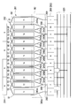
- FIG. 19 is a development view of the armature, and the gaps between adjacent teeth T1 to T10 correspond to the slots S1 to S10.
- each segment 268 is described with reference numerals.
- each of the risers 269 between the segments 268 having the same potential that is, the risers 269 between the four segments 268 that exist in the circumferential direction in the fourth embodiment, (Equal pressure line) 225 is wound around.
- the connection line 225 is for short-circuiting the segments 268 having the same potential, and is fixed to the riser 269 by fusing.
- the winding method of the winding 243 around the armature core 261 is a so-called distributed winding method in which the winding 243 is wound between every other slot S1 to S10. It has become.
- the winding start end 243a of the winding 243 is hung around the riser 269 of the first segment 268, and the first segment 268 and the winding 243 are connected. Thereafter, the winding 243 is pulled into the first slot S1. And it winds n times (n is a natural number) between this 1st slot S1 and 3rd slot S3, and forms the 1st coil C1.
- the winding end 243b of the first coil C1 is drawn into the sixth slot S6. And it winds n times between this 6th slot S6 and 8th slot S8, and forms 1'th coil C1 '. Further, the winding end 243 b of the 1 ′ coil C 1 ′ is wound around the riser 269 of the 7th segment 268 having the same potential as the 2nd segment 268 adjacent to the 1st segment 268, and the 7th segment 268 and the winding 243 are Connect. Thereby, the winding process of the 1st coil C1 and 1'th coil C1 'is completed.
- the first coil C1 and the 1′th coil C1 ′ are coils that are first formed on the armature core 261, they are formed in a state closest to the inner side in the radial direction of the armature core 261.
- the winding start end 243 a of the winding 243 is wound around the riser 269 of the second segment 268, and the second segment 268 and the winding 243 are connected, and then the winding 243 Is drawn into the second slot S2. And it winds n times between this 2nd slot S2 and 4th slot S4, and forms the 2nd coil C2.
- the winding end 243b of the second coil C2 is pulled into the seventh slot S7. And it winds n times between this 7th slot S7 and 9th slot S9, and forms 2'th coil C2 '. Further, the winding end 243 b of the 2 ′ coil C 2 ′ is wound around the riser 269 of the 8th segment 268 having the same potential as the 3rd segment 268 adjacent to the 2nd segment 268, and the 8th segment 268 and the winding 243 are Connect. Thereby, the winding process of the second coil C2 and the 2'th coil C2 'is completed.
- the previously formed first coil C1 is stretched over the second slot S2 into which the winding 243 of the second coil C2 is drawn. For this reason, in the 2nd slot S2, the 2nd coil C2 will be in the state formed in the radial direction outer side of the 1st coil C1. On the other hand, in the 4th slot S4, the 2nd coil C2 is in a state of being closest to the radially inner side.
- the 2'th coil C2 ' is the same as the 1'th coil C1'.
- the winding start end 243 a of the winding 243 is wound around the riser 269 of the third segment 268 to connect the third segment 268 and the winding 243, and then the winding 243. Is drawn into the third slot S3. And it winds n times between this 3rd slot S3 and 5th slot S5, and forms the 3rd coil C3.
- the winding end 243b of the third coil C3 is pulled into the eighth slot S8. And it winds n times between this 8th slot S8 and 10th slot S10, and forms 3'th coil C3 '. Further, the winding end 243b of the 3 ′ coil C3 ′ is wound around the riser 269 of the 9th segment 268 having the same potential as the 4th segment 268 adjacent to the 3rd segment 268, and the 9th segment 268 and the winding 243 Connect. Thereby, the winding process of the third coil C3 and the 3'th coil C3 'is completed.
- the third slot S3 into which the winding 243 of the third coil C2 is drawn the previously formed first coil C1 is drawn and the second coil C2 is stretched.
- the third coil C3 is formed in a state of being closest to the radially outer side of the armature core 261.
- the third coil C3 is in a state of being closest to the inner side in the radial direction.
- the 3'th coil C3 ' is the same as the 1'th coil C1' and the 2'th coil C2 '.
- the winding start end 243 a of the winding 243 is wound around the riser 269 of the fourth segment 268 to connect the fourth segment 268 and the winding 243, and then the winding 243.
- the winding start end 243 a of the winding 243 is wound around the riser 269 of the fourth segment 268 to connect the fourth segment 268 and the winding 243, and then the winding 243.
- the winding start end 243 a of the winding 243 is wound around the riser 269 of the fourth segment 268 to connect the fourth segment 268 and the winding 243, and then the winding 243.
- the fourth slot S4 winds n times between this 4th slot S4 and 6th slot S6, and forms the 4th coil C4.
- the winding end 243b of the fourth coil C4 is drawn into the ninth slot S9. And it winds n times between this 9th slot S9 and 1st slot S1, and forms 4'th coil C4 '. Further, the winding end 243b of the 4′-th coil C4 ′ is wound around the riser 269 of the 10th segment 268 having the same potential as the 5th segment 268 adjacent to the 4th segment 268, and the 10th segment 268 and the winding 243 Connect. Thereby, the winding process of the 4th coil C4 and the 4'th coil C4 'is completed.
- the fourth slot S4 in which the winding 243 of the fourth coil C4 is drawn, the previously formed second coil C2 is drawn and the third coil C3 is stretched. For this reason, in the fourth slot S4, the fourth coil C4 is formed in a state of being closest to the radially outer side of the armature core 261. On the other hand, in the sixth slot S6, the fourth coil C4 is in a state of being closest to the inner side in the radial direction.
- the 4'th coil C4 ' is the same as the 2'th coil C2' and the 3'th coil C3 '.
- the winding start end 243 a of the winding 243 is wound around the riser 269 of the fifth segment 268 to connect the fifth segment 268 and the winding 243, and then the winding 243.
- the winding start end 243 a of the winding 243 is wound around the riser 269 of the fifth segment 268 to connect the fifth segment 268 and the winding 243, and then the winding 243.
- the winding end 243b of the fifth coil C5 is pulled into the tenth slot S10. And it winds n times between this 10th slot S10 and 2nd slot S2, and forms 5 'coil C5'. Further, the winding end 243 b of the 5 ′ coil C 5 ′ is wound around the riser 269 of the 1st segment 268 having the same potential as the 6th segment 268 adjacent to the 5th segment 268, and the 1st segment 268 and the winding 243 are Connect. Thereby, the winding process of the 5th coil C5 and the 5'th coil C5 'is completed. As described above, the armature coil 262 is formed on the armature core 261 through the winding process of sequentially forming the coils C1 to C5 ′ in the winding direction Y1.
- the fifth slot S5 into which the winding 243 of the fifth coil C5 is drawn the previously formed third coil C3 is drawn and the fourth coil C4 is stretched. Therefore, in the fifth slot S5, the fifth coil C5 is formed in a state closest to the outer side in the radial direction of the armature core 261. On the other hand, in the seventh slot S6, the previously formed 1'-th coil C1 'is drawn. For this reason, in the seventh slot S7, the fifth coil C5 is formed on the radially outer side of the 1'th coil C1 '.
- the fourth embodiment by setting the armature core 261 to the deformed core shown in FIG. 17, an extra gap is formed between the coils C1 to C5 ′ that are sequentially formed in the winding direction Y1. Therefore, it is possible to suppress the generation of useless spaces in the slots S1 to S10. Therefore, the space factor of the armature coil 262 can be improved, and the coils can be distributed in a balanced manner in the slots S1 to S10. As a result, the electric motor 201 can be reduced in size and weight.
- each of the teeth T1 to T10 is composed of two tooth groups 251 and 252 that are point-symmetric with each other, and therefore, the rotation unbalance of the armature 206 may occur. Can be prevented.
- the peripheral wall 281 of the yoke 208 is constituted by a pair of flat portions 281a that are arranged to face each other around the rotation shaft 212, and arc-shaped portions 281b that connect the circumferential ends of the pair of flat portions 281a.
- the yoke 208 can be flattened. Therefore, the entire electric motor 201 can be flattened, and the degree of freedom of layout of the electric motor 201 can be increased.
- each flat portion 281a is arranged at intervals of 90 ° in the circumferential direction of the peripheral wall 281 and the circumferential ends of each flat portion 281a are connected to each other by arc-shaped portions 281b. It is also possible to provide four permanent magnets 214 on the inner surface of each arcuate portion 281b so as to avoid the flat portions 281a.
- the number of the flat portions 281a formed on the peripheral wall 281 is set to two that are opposed to each other around the rotation shaft 212, thereby flattening the yoke 208. The deterioration of the motor characteristics can be suppressed while being achieved.
- the winding start end 243a and the winding end end 243b of the armature coil 262 (coils C1 to C5 ′) wound around the armature core 261 are as shown in a region R1 surrounded by a broken line in FIG. The case where it was drawn was explained. However, the present invention is not limited to the case shown in FIG. 19, and the coils C1 to C5 'may be connected to the segment 268 having a predetermined potential.
- the first coil C1 and the 1'th coil C1 ' are wound in series
- the second coil C2 and the 2'th coil C2' are wound in series
- 3 'coil C3' are wound in series
- 4th coil C4 and 4 'coil C4' are wound in series
- 5th coil C5 and 5 'coil C5' are wound in series.
- the case where the armature coil 262 is formed by mounting is described.
- the present invention is not limited to this, and the armature coil 262 may be formed as follows.
- FIG. 20 is a development view of the armature in the first modification of the fourth embodiment.
- the 1st to 5th coils C1 to C5 and the 1'th to 5'th coils C1 'to C5' are connected in parallel to each other. That is, the winding start end 243a of the winding 243 forming the first coil C1 is connected to the first segment 268, while the winding end 243b is connected to the second segment 268.
- the winding start end 243a of the winding 243 forming the second coil C2 is connected to the second segment 268, while the winding end 243b is connected to the third segment 268.
- the winding start end 243a of the winding 243 forming the third coil C3 is connected to the third segment 268, while the winding end 243b is connected to the fourth segment 268.
- the winding start end 243a of the winding 243 forming the fourth coil C4 is connected to the fourth segment 268, while the winding end 243b is connected to the fifth segment 268.
- the winding start end 243a of the winding 243 forming the fifth coil C5 is connected to the fifth segment 268, while the winding end 243b is connected to the sixth segment 268.
- the winding 243 forming the 1 ′ coil C1 ′ is connected to the 1st segment 268 and the 6th segment 268 and the 7th segment 268 having the same potential as the 2nd segment 268, and the 2′th coil
- the winding 243 forming the coil C2 ′ is connected to the 7th segment 268 and the 8th segment 268 having the same potential as the 2nd segment 268 and the 3rd segment 268, and the winding forming the 3′th coil C3 ′.
- the wire 243 is connected to the No. 3 segment 268 and the No. 8 segment 268 and No. 9 segment 268 having the same potential as the No. 4 segment 268, and the winding 243 forming the No. 4 ′ coil C4 ′ is the No.
- the winding method of the first coil C1 to 5 ′ coil C5 ′ formed in this way is to sequentially wind the first coil C1 and the 1 ′ coil C1 ′, and from the second coil C2 in the same manner.
- a method of winding up to the 5'th coil C5 'in order can be employed.
- the first coil C1 and the 1 'coil C1' which are opposed to each other around the rotating shaft 212, are wound simultaneously, and the second coil C2, the 2 'coil C2', and the third coil, respectively.
- the number of parallel circuits is doubled compared to the winding method of FIG.
- the wire diameter of 243 can be reduced. For this reason, the winding work of the winding 243 can be facilitated.
- the winding start end 243a and winding end end 243b of the armature coil 262 (coils C1 to C5 ′) wound around the armature core 261 are shown in a region R2 surrounded by a broken line in FIG. Explained the case of being drawn around.
- the present invention is not limited to the case shown in FIG. 20, and the winding start end 243a and winding end 243b of each of the coils C1 to C5 ′ may be connected to the segment 268 having a predetermined potential.
- FIG. 21 is a longitudinal sectional view of the electric motor.
- an electric motor 401 is a drive source for electrical components mounted on a vehicle, and has a configuration in which an armature 403 is rotatably disposed in a bottomed cylindrical yoke 402. .
- Four permanent magnets 404 are arranged on the inner peripheral surface of the yoke 402 in the circumferential direction so that the magnetic poles are in order.
- the electric motor 401 is in a state in which four magnetic poles are formed in the yoke 402.
- the armature 403 includes an armature core 406 that is externally fixed to the rotary shaft 405, an armature coil 407 that is wound around the armature core 406, and a commutator 413 that is disposed on one end side of the armature core 406.
- the armature core 406 is formed by laminating a plurality of ring-shaped metal plates 408 in the axial direction. Ten T-shaped teeth 409 in an axial plan view are radially formed on the outer peripheral portion of the metal plate 408 at equal intervals along the circumferential direction.
- dovetail-shaped slots 411 are formed between adjacent teeth 409 on the outer periphery of the armature core 406.
- Ten slots 411 extend along the axial direction and are formed at equal intervals along the circumferential direction.
- An enameled winding 412 is wound between the slots 411, whereby a plurality of armature coils 407 are formed on the outer periphery of the armature core 406.
- the commutator 413 is fitted and fixed to one end of the rotating shaft 405.
- Ten segments 414 made of a conductive material are attached to the outer peripheral surface of the commutator 413.
- the segment 414 is made of a plate-like metal piece that is long in the axial direction, and is fixed in parallel at equal intervals along the circumferential direction while being insulated from each other.
- a riser 415 is integrally formed at the end of each segment 414 on the armature core 406 side, and is bent in a manner of folding back to the outer diameter side.
- the riser 415 is wound around a winding start end 431 and a winding end end 432 (see FIG.
- the other end side of the rotating shaft 405 is rotatably supported by a bearing 416 in a boss protruding from the yoke 402.
- a cover 417 is provided at the open end of the yoke 402, and a holder stay 418 is attached to the inside of the cover 417.
- the holder stay 418 is provided with two brush holders 419 at a predetermined angle (90 degrees in the fifth embodiment) in the circumferential direction.
- Each brush holder 419 is internally provided with a brush 421 that can be moved in and out in a state where the brush 421 is biased via a spring S.
- the tip portions of the brushes 421 are biased by the spring S and are in sliding contact with the commutator 413, so that power from the outside is supplied to the commutator 413 through the brush 421.
- FIG. 22 is a developed view of the segment 414 (riser 415) of the armature 403, the teeth 409, and the permanent magnet 404 disposed on the yoke 402 side, and the gap between the adjacent teeth 409 corresponds to the slot 411.
- each segment 414 and each tooth 409 are numbered in order along the rotational direction, and the wound winding 412 is given a reference numeral.
- the rotation direction of the armature 403 (hereinafter simply referred to as the rotation direction) is the right direction.
- the armature coil 407 formed on the outer periphery of the armature core 406 is formed by winding the winding 412 in a distributed winding manner so as to straddle two adjacent teeth 409, 409, and the U-phase, V It has a five-phase structure of phase, W phase, X phase, and Y phase. And the armature coil 407 of each phase is formed in two places so that it may oppose centering on the rotating shaft 405, respectively.
- the armature coil 407 includes a first U-phase coil 471U, a second U-phase coil 472U, a first V-phase coil 471V, a second V-phase coil 472V, a first W-phase coil 471W, a second W-phase coil 472W, a first X-phase coil 471X, It is composed of a 2X phase coil 472X, a first Y phase coil 471Y, and a second Y phase coil 472Y.
- connection line 425 The armature coil 407 and the connection line 425 having such a configuration are formed by drawing the winding 412 in series with each other. More specific description will be given below.
- the winding 412 is drawn into the slot 411 between the 7th to 8th teeth 409 and 409 that is located substantially opposite to the 1st segment 414 around the rotation axis 405. Then, a slot 411 between the 7th and 8th teeth 409 and 409 and a slot 411 between the 5th and 6th teeth 409 and 409 that are present by skipping one slot 411 opposite to the rotation direction from here.
- the winding 412 is wound N times (N is a natural number) between them, and a first U-phase coil 471U is formed.
- the winding 412 forming the first U-phase coil 471U is pulled out from the slot 411 between the 5th and 6th teeth 409 and 409, and after being routed in the rotational direction, the 2nd and 3rd teeth 409 and 409 are arranged. It is drawn into the slot 411 in between. Then, a slot 411 between No. 2 and No. 3 teeth 409 and 409 and a slot 411 between No. 10 and No. 1 teeth 409 and 409 existing by skipping one slot 411 opposite to the rotation direction from here. Winding 412 is wound N times in the middle to form second U-phase coil 472U.
- the winding 412 is pulled out from a slot 411 between No. 10 and No. 1 teeth 409 and 409, and is present at a position almost opposite to the slot 411 with the rotation shaft 405 as the center, and the No. 6 segment 414. Is swung around the riser 415 of the 7th segment 414 adjacent to. Further, the winding 412 is wound around the riser 415 of the second segment 414 having the same potential as the seventh segment 414. Thereby, the connection line 425 which short-circuits the 7th segment 414 and the 2nd segment 414 is formed.
- the winding 412 is drawn into the slot 411 between the No. 8 and No. 9 teeth 409 and 409, which is located almost opposite to the No. 2 segment 414 around the rotation axis 405, and No. 8 and No. 9
- the winding 412 is N between the slot 411 between the teeth 409 and 409 and the slot 411 between the sixth to seventh teeth 409 and 409 that is present by skipping one slot 411 opposite to the rotation direction from here.
- the first V-phase coil 471V is formed by winding.
- the winding 412 forming the first V-phase coil 471V is pulled out from the slot 411 between the 6th-7th teeth 409, 409 and routed in the rotational direction, and then the 3rd-4th teeth 409,409. It is drawn into the slot 411 in between. Then, a slot 411 between the third and fourth teeth 409 and 409 and a slot 411 between the first and second teeth 409 and 409 existing by skipping one slot 411 opposite to the rotation direction from here. Winding 412 is wound N times in between, and second V-phase coil 472V is formed.
- the winding 412 is pulled out from the slot 411 between the first and second teeth 409 and 409, and is present at a position almost opposite to the slot 411 with the rotation axis 405 as the center, and the seventh segment 414. Is hung around the riser 415 of the eighth segment 414 adjacent to. Further, the winding 412 is wound around the riser 415 of the third segment 414 having the same potential as the eighth segment 414. Thereby, the connection line 425 which short-circuits the 8th segment 414 and the 3rd segment 414 is formed.
- first U-phase coil 471U to the second V-phase coil 472V are formed between the slot 411 between the 9th to 10th teeth 409 and 409 and between the 7th to 8th teeth 409 and 409
- the first W-phase coil 471W is formed between the slot 411 and the second W-phase between the slot 411 between the fourth and fifth teeth 409 and 409 and the slot 411 between the second and third teeth 409 and 409.
- a coil 472W is formed.
- the winding 412 is again wound around the riser 415 of the corresponding segment 414, and then the winding 412 is wound around the segment 414 having the same potential. And the connection line 425 which short-circuits between the segments 414 used as the same electric potential is formed. Thereafter, the winding 412 is again drawn out to the armature core 406 side, and the first X-phase coil 471X and the second X-phase coil 472X are formed between the predetermined slots 411.
- the winding 412 is again wound around the riser 415 of the corresponding segment 414, and further the winding 412 is wound around the segment 414 having the same potential to form the connection line 425. Then, the winding 412 is again drawn out to the armature core 406 side, and the first Y-phase coil 471Y and the second Y-phase coil 472Y are formed between the predetermined slots 411. After the second Y-phase coil 472 is formed, the winding end 432 of the winding 412 is wound around and connected to the riser 415 of the first segment 414. Thereby, the formation of the armature coil 407 wound around the armature core 406 is completed.
- the winding 412 is arranged so as to repeatedly move between the segment 414 and the armature core 406 in the manner of one stroke, thereby forming the armature coil 407 and the connection line 425 in series.
- the winding 412 when the winding 412 is routed from the segment 414 toward the armature core 406, the riser 415 of the segment 414 from which the winding 412 is drawn and the slot 411 into which the winding 412 is drawn are centered on the rotating shaft 405. It exists in the almost opposite position.
- the slot 411 from which the winding 412 is drawn and the riser 415 of the segment 414 around which the winding 412 is wound are centered on the rotating shaft 405. Exist at almost opposite positions. For this reason, the winding 412 routed between the commutator 413 and the armature core 406, that is, the winding 412 routed under the neck of the commutator 413 is slightly engaged with the rotating shaft 405.
- the armature coil 407 and the connection line 425 when forming the armature coil 407 and the connection line 425, the armature coil 407 and the connection line are arranged by arranging the winding 412 so as to repeatedly move in the manner of one stroke. Since the 425 can be formed in series, the total time of the winding time of the winding 412 around the armature core 406 and the time of forming the connection line 425 between the segments 414 can be shortened. As a result, the manufacturing cost of the electric motor 401 can be reduced.
- winding 412 arranged under the neck of the commutator 413 is slightly hooked on the rotating shaft 405, the winding 412 under the neck of the commutator 413 is prevented from being loosened radially outward. it can. For this reason, the winding thickness of the coil
- FIG. 23 is an expanded view of the segment 414 (the riser 415), the teeth 409, and the permanent magnet 404 disposed on the yoke 402 side of the armature 403 in the sixth embodiment.
- the electric motor 401 is a motor having four permanent magnets 404, ten slots 411, and ten segments 414.
- the armature coil 407 formed on the outer periphery of the armature core 406 is: Formed by winding the winding 412 in a distributed winding manner so as to straddle two adjacent teeth 409, 409, and has a five-phase structure of U phase, V phase, W phase, X phase, Y phase. And the armature coils 407 of each phase are formed at two locations so as to face each other around the rotation axis 405, and the segments 414 having the same potential, that is, around the rotation axis 405.
- the basic configuration such as the two segments 414 facing each other being short-circuited by the connection line 425 is the same as that of the fifth embodiment (the following embodiments) But the same).
- the armature coil 407 wound around the armature core 406 of the sixth embodiment and the connection line 425 connected between the segments 414 having the same potential are wound by winding the winding 412 by a so-called double flyer system. It is formed.
- the double flyer method refers to a method in which the winding 412 is wound simultaneously at two points in a point-symmetrical relationship with respect to the rotation shaft 405. More specific description will be given below.
- the winding 412 in which the winding start end 431 is wound around the riser 415 of the sixth segment 414 includes a first U-phase coil 471U, a first V-phase coil 471V, a first W-phase coil 471W, a first X-phase coil 471X, and A first Y-phase coil 471Y and a connecting line 425 connected to the segment 414 corresponding to these coils 471U to 471Y are formed in series.
- the winding 412 in which the winding start end 431 is wound around the riser 415 of the first segment 414 includes a second U-phase coil 472U, a second V-phase coil 472V, a second W-phase coil 472W, a second X-phase coil 472X, and A second Y-phase coil 472Y and a connection line 425 connected to the segment 414 corresponding to these coils 472U to 472Y are formed in series.
- Line 425 and a connection connected to the second U-phase coil 472U, the second V-phase coil 472V, the second W-phase coil 472W, the second X-phase coil 472X, the second Y-phase coil 472Y, and the segment 414 corresponding to these coils 472U to 472Y.
- Line 425 is formed simultaneously.
- the winding method of the winding 412 in which the winding start end 431 is wound around the riser 415 of the sixth segment 414 will be described in more detail.
- the winding start end 431 of the winding 412 is wound around the riser 415 of the sixth segment 414, and then the winding 412 is wound around the riser 415 of the first segment 414 having the same potential as the sixth segment 414.
- a connection line 425 that short-circuits the sixth segment 414 and the first segment 414 is formed.
- winding 412 is drawn into the slot 411 between the 7th to 8th teeth 409 and 409 that is located substantially opposite to the 1st segment 414 around the rotation axis 405. Then, a slot 411 between the 7th and 8th teeth 409 and 409 and a slot 411 between the 5th and 6th teeth 409 and 409 that are present by skipping one slot 411 opposite to the rotation direction from here. Winding 412 is wound N times in between, and first U-phase coil 471U is formed.
- the winding 412 forming the first U-phase coil 471U is pulled out from the slot 411 between the 5th and 6th teeth 409 and 409 and routed in the rotational direction, and then the 7th adjacent to the 6th segment 414. It is hung around the riser 415 of the segment 414. Further, the winding 412 is wound around the riser 415 of the second segment 414 having the same potential as the seventh segment 414. Thereby, the connection line 425 which short-circuits the 7th segment 414 and the 2nd segment 414 is formed.
- the winding 412 is drawn into the slot 411 between the No. 8 and No. 9 teeth 409 and 409, which is located almost opposite to the No. 2 segment 414 around the rotation axis 405, and No. 8 and No. 9
- the winding 412 is N between the slot 411 between the teeth 409 and 409 and the slot 411 between the sixth to seventh teeth 409 and 409 that is present by skipping one slot 411 opposite to the rotation direction from here.
- the first V-phase coil 471V is formed by winding.
- the winding 412 forming the first V-phase coil 471V is pulled out from the slot 411 between the 6th and 7th teeth 409 and 409 and routed in the rotational direction, and then the 8th adjacent to the 7th segment 414. It is hung around the riser 415 of the segment 414. Further, the winding 412 is wound around the riser 415 of the third segment 414 having the same potential as the eighth segment 414. Thereby, the connection line 425 which short-circuits the 8th segment 414 and the 3rd segment 414 is formed.
- the first W-phase coil 71 ⁇ / b> W is formed with the slot 411.
- the winding 412 is again wound around the riser 415 of the corresponding segment 414, and then the winding 412 is wound around the segment 414 having the same potential.
- the connection line 425 which short-circuits between the segments 414 used as the same electric potential is formed.
- the winding 412 is again drawn out to the armature core 406 side, and the first X-phase coil 471X is formed between the predetermined slots 411.
- the winding 412 is again wound around the riser 415 of the corresponding segment 414, and further the winding 412 is wound around the segment 414 having the same potential to form the connection line 425. Then, the winding 412 is again drawn out to the armature core 406 side to form the first Y-phase coil 471Y between the predetermined slots 411, and then the winding end 432 of the winding 412 is wound around the riser 415 of the first segment 414. Connected.
- the first U-phase coil 471U, the first V-phase coil 471V, the first W-phase coil 471W, the first X-phase coil 471X, the first Y-phase coil 471Y, and these Connection lines 425 connected to the segments 414 corresponding to the coils 471U to 471Y are formed.
- the winding 412 in which the winding start end 431 is wound around the riser 415 of the first segment 414 is wound around the winding 412 in which the winding start end 431 is wound around the riser 415 of the sixth segment 414.
- the second U-phase coil 472U, the second V-phase coil 472V, the second W-phase coil 472W, the second X-phase coil 472X, the second Y-phase coil 472Y, and the like The connection line 425 connected to the segment 414 corresponding to the coils 472U to 472Y is formed. Thereby, the formation of the entire armature coil 407 wound around the armature core 406 is completed.
- FIG. 24 is a developed view of the segment 414 (riser 415) and teeth 409 of the armature 403 and the permanent magnet 404 disposed on the yoke 402 side in the seventh embodiment.
- the difference between the winding method of the winding 412 of the fifth embodiment and the winding method of the winding 412 of the seventh embodiment is that the phase coils 471U to 472Y of the fifth embodiment are different. Is formed by winding the winding 412 N times at a time, whereas each phase coil 471U to 472Y of the seventh embodiment has two small coils each wound N / 2 times. 571U to 672Y.
- FIG. 24 there are two winding start ends 431 of the winding 412 as in the sixth embodiment.
- the two winding start ends 431 and 431 when one winding start end 431 is wound around the riser 415 of the 6th segment 414, for example, the 1st segment 414 having the same potential as that of the 6th segment 414 is subsequently provided.
- the winding 412 is wound around the riser 415.
- a connection line 425 that short-circuits the sixth segment 414 and the first segment 414 is formed.
- the winding 412 is drawn into the slot 411 between the 7th and 8th teeth 409 and 409, the slot 411 between the 7th and 8th teeth 409 and 409, and the slot between the 5th and 6th teeth 409 and 409.
- the coil 412 is wound N / 2 times between the coil 411 and the first U-phase small coil 571U.
- the winding 412 forming the first U-phase small coil 571U is pulled out from the slot 411 between the 5th-6th teeth 409, 409 and routed in the rotational direction, and then the 2nd-3rd teeth 409, 409 is drawn into the slot 411 between 409.
- the winding 412 is wound N / 2 times between the slot 411 between the second and third teeth 409 and 409 and the slot 411 between the tenth and first teeth 409 and 409, and the second U-phase small A coil 572U is formed.
- the winding 412 is drawn from the slot 411 between the 10th and 1st teeth 409 and 409 and is wound around the riser 415 of the 7th segment 414 adjacent to the 6th segment 414. Further, the winding 412 is wound around the riser 415 of the second segment 414 having the same potential as the seventh segment 414. Thereby, the connection line 425 which short-circuits the 7th segment 414 and the 2nd segment 414 is formed.
- the first V-phase small coil 571V to the second Y-phase small coil 572Y and the connection line 425 are sequentially formed by the winding 412.
- the winding procedure of the first V-phase small coil 571V to the second Y-phase small coil 572Y is the same as that in the fifth embodiment, and thus the description thereof is omitted.
- the number of windings of the winding 412 wound between the slots 411 and 411 is N / 2, which is half that of the fifth embodiment.
- the winding 412 in which the other winding start end 431 is wound around the riser 415 of the first segment 414 having the same potential as the sixth segment 414 is wound around the riser 415 of the sixth segment 414.
- the first U-phase small coil 671V to the second Y-phase small coil 672Y and the connection line 425 are sequentially formed while being arranged so as to be point-symmetric about the rotating shaft 405 when winding is performed. To go.
- the winding 412 is wound around the riser 415 of the sixth segment 414. Then, a connection line 425 for short-circuiting the first segment 414 and the sixth segment 414 is formed. Next, the winding 412 is drawn into the slot 411 between the second and third teeth 409 and 409, and the slot 411 between the second and third teeth 409 and 409 and the slot between the tenth and first teeth 409 and 409 Winding 412 is wound N / 2 times between 411 and 411 to form a second U-phase small coil 672U.
- the winding 412 forming the second U-phase small coil 672U is pulled out from the slot 411 between the 10th and 1st teeth 409 and 409 and routed in the rotational direction, and then the 7th and 8th teeth 409, 409 is drawn into the slot 411 between 409.
- the winding 412 is wound N / 2 times between the slot 411 between the 7th and 8th teeth 409 and 409 and the slot 411 between the 5th and 6th teeth 409 and 409, and the first U-phase small A coil 671U is formed.
- the winding 412 is pulled out from the slot 411 between the 5th and 6th teeth 409 and 409 and is wound around the riser 415 of the 2nd segment 414 adjacent to the 1st segment 414. Further, the winding 412 is wound around the riser 415 of the seventh segment 414 having the same potential as the second segment 414. Thereby, the connection line 425 which short-circuits the 2nd segment 414 and the 7th segment 414 is formed.
- each phase coil 471U to 472Y is constituted by two small coils 571U to 672Y wound N / 2 times, and forms coils 471U to 472Y wound N times as a whole.
- the winding 412 can be wound using a so-called double flyer system, and thus the same effect as that of the sixth embodiment can be obtained.
- the small coils 571U to 572Y and the small coils 671U to 672Y of the same phase can be connected in series while adopting the double flyer system. That is, for example, the first U-phase small coil 571U and the second U-phase small coil 572U are connected in series.
- the same current is stably supplied to the coils in the same phase in the first respective phase coils 471U to 471Y and the second respective phase coils 472U to 472Y.
- the first phase coils 471U to 471Y and the second phase coils 472U to 472Y are formed by different windings 412 as in the sixth embodiment, some winding errors, etc.
- the length of the conducting wire changes, and different currents may be supplied even in coils in the same phase.
- the in-phase small coils 571U to 572Y and the small coils 671U to 672Y are connected in series, the same current is stably supplied to the in-phase coils.
- the magnetic field formed by the coils 471U to 472Y of the respective phases can be stabilized, and the electric motor 401 having an excellent magnetic balance can be provided.
- the durability of the brush 421 can be improved.
- the present invention is not limited to this, and the number of brushes 421 can be increased to four, which is the same number as the number of poles.
- the present invention is not limited to the above-described embodiment, and includes various modifications made to the above-described embodiment without departing from the spirit of the present invention.
- the electric motor by forming the first flat portion on the cylindrical portion of the yoke, the electric motor can be made smaller than when the cylindrical portion is formed in a cylindrical shape. Further, by arranging the permanent magnet at a position avoiding the first flat portion, the electric motor can be reduced in size without depending on the thickness of the permanent magnet.
Landscapes
- Engineering & Computer Science (AREA)
- Power Engineering (AREA)
- Microelectronics & Electronic Packaging (AREA)
- Dc Machiner (AREA)
- Iron Core Of Rotating Electric Machines (AREA)
Description
巻線に電流が供給されると磁界が形成され、この磁界と永久磁石との間に生じる磁気的な吸引力や反発力によってアーマチュアが回転する。
例えば、略有底筒状のヨークと、コネクタ部が形成され前記ヨークを閉塞するように固定されるエンドブラケットと、を備えた電動モータであって、エンドブラケットに、サーミスタ及び雑防素子(本願の「コンデンサ」及び「チョークコイル」に相当)を搭載した電動モータが提案されている(例えば、特許文献2参照)。
また、アーマチュアコアに巻線を巻装する工程と、同電位のセグメントに接続線を接続する工程とを別々に行う必要がる。このため、アーマチュアへのコイルの巻装時間、及びセグメントへの接続線の接続時間の総時間が長くなり、この結果、製造コストが高くなるという可能性がある。
そして、コネクタ部は、エンドブラケットの外周壁から突出して形成されている。そして、コネクタ部の内部に配置された給電用ターミナル間には、雑防素子が配置されている。したがって、この様な構成では、コネクタ部を小型化してエンドブラケットの更なる小型化を図るのには限界がある。
この結果、電動モータの小型化、軽量化を図りにくいという可能性がある。
また、アーマチュアへのコイルの巻装時間、及びセグメントへの接続線の接続時間の総時間を短縮し、製造コストを低減できる電動モータを提供することを目的とする。
さらに、スロットに無駄なスペースが生じてしまうことを防止しつつ、コイルの占積率を向上させることができる電動モータを提供することを目的とする。
また、アーマチュアコア自体が異形状に形成されているものの、回転軸を中心に点対称形状になるので、アーマチュアの回転アンバランスが生じてしまうことをより確実に防止できる。
以下に、図1及び図2を用いて第1実施形態の電動モータ2及びこの電動モータ2を用いた減速機構付モータ装置1(請求項の「駆動装置」に相当)の説明をする。
図1及び図2に示す電動モータ2を用いた減速機構付モータ装置1は、例えば車両のパワーウィンドウ、サンルーフ、電動シート及びワイパ装置の少なくとも何れか1つの駆動用として用いられる。
電動モータ2は、ヨーク5の筒部53内にアーマチュア6が回転自在に設けられ、筒部53の開口部53b側に形成されたブラシホルダ収納部90に、ブラシホルダ22が内嵌固定されたものである。
ヨーク5は、例えば鉄等の金属からなる有底筒状の部材であり、例えば深絞りによるプレス加工等により成型される。
第1平坦部61の離間距離は、筒部53内に配置されるアーマチュア6の直径よりも若干広くなるように設定される。
弧状部63は、対向する第1平坦部61のそれぞれの周方向端部を連結している。弧状部63の曲率中心は、軸方向から見てアーマチュア6の回転中心と同一となるように設定される。また、弧状部63の内周面63aの曲率半径は、アーマチュア6の半径よりも若干大きくなるように設定される。
L1<R1・・・(1)
を満たすように設定されている。
ブラシホルダ収納部90は、短手方向で対向する1対の平坦壁91と、長手方向において平坦壁91の周方向端部を連結する1対の弧状壁92とを有している。
前述のとおり、第1平坦部61の幅L1、及び弧状部63の幅R1は(1)式を満たしている。したがって、筒部53に設けられた1対の第1平坦部61、及び1対の弧状部63のうち、より狭小な幅L1を有する1対の第1平坦部61が、ブラシホルダ22の短手方向に配置される。
外フランジ部52は、ブラシホルダ収納部90の長手方向に沿って長くなるように軸方向平面視略5角形状に形成され、且つ頂点となる部分が長手方向に位置するように形成されている。また、外フランジ部52の短手方向の幅は、ブラシホルダ収納部90に設けられた1対の平坦壁91の幅よりも若干大きくなるように設定されている。
ヨーク5の筒部53内に回転自在に設けられたアーマチュア6は、回転軸3に外嵌固定されたアーマチュアコア8と、アーマチュアコア8に巻装されたアーマチュアコイル(不図示)と、回転軸3の他端側に配置されたコンミテータ10とを備えている。アーマチュアコア8は、電磁鋼板等からなるリング状の板部材11を軸方向に複数枚積層したものである。
また、ティース12が周方向に沿って等間隔に配置されているため、各スロット13も周方向に沿って等間隔に複数形成される。
セグメント15は、軸線方向に長い板状の金属片により形成されている。そして、セグメント15は、互いに離間して絶縁された状態で周方向に沿って等間隔に並列に固定されている。したがって、電動モータ2は、永久磁石7が4個、スロット13が10スロット、セグメント15が10枚の、4極10スロット10セグメントで構成された直流モータとなっている。
ウォームギヤ減速機構4には、ウォーム軸25及びウォームホイール26を収納するギヤハウジング23が設けられている。
第1実施形態によれば、ヨーク5の筒部53に第1平坦部61を形成することにより、筒部53を円筒状に形成した場合よりも、電動モータ2を小型化することができる。また、第1平坦部61を避けた位置に永久磁石7を配置することで、永久磁石7の厚さに依存することなく電動モータ2の小型化を図ることができる。
次に、第1実施形態の変形例について、図3及び図4を用いて説明する。第1実施形態の電動モータ2には、ヨーク5に1対の第1平坦部61が形成されていた。しかし、本変形例の電動モータ2には、ヨーク5に2対の第1平坦部61が形成されており、隣接する各第1平坦部61を跨るように2対の弧状部63が形成されている点で、第1実施形態の電動モータ2とは異なっている。尚、第1実施形態と同様の構成部分については、詳細な説明を省略する。
L1<R1・・・(1)
を満たすように設定されている。
第1実施形態の変形例によれば、弧状部63の幅よりも狭い幅を有する2対の第1平坦部61を形成することで、ブラシホルダの短手方向に加えて、長手方向においても電動モータ2の筒部53の小型化ができる。したがって、第1実施形態の効果に加えて、レイアウト性に優れた小型な電動モータ2、及びこの電動モータ2を使用した小型な減速機構付モータ装置1の提供ができる。
(断面8角形のヨーク)
次に、第2実施形態について、図5及び図6を用いて説明する。第1実施形態では、1対の第1平坦部61と、1対の弧状部63とにより、筒部53が断面略長円形状に形成されていた。また、第1実施形態の変形例では、2対の第1平坦部61と、2対の弧状部63とにより、筒部53が断面略長円形状に形成されていた。
しかし、第2実施形態では、筒部53が断面8角形状に形成されている点で、第1実施形態の電動モータ2とは異なっている。尚、第1実施形態及び第1実施形態の変形例と同様の構成部分については、詳細な説明を省略する。
さらに、対向する第1平坦部61の幅をL1とし、対向する第2平坦部62の幅をL2としたとき、第1平坦部61の幅L1、及び第2平坦部62の幅L2が、
L1<L2・・・(2)
を満たすように設定されている。
本実施形態によれば、筒部53を断面8角形状に形成することで、第1実施形態のように筒部53に弧状部63(図2参照)を形成した場合よりも、さらに電動モータ2の小型化ができる。
また、第2平坦部62の内面62aに永久磁石7を固定するので、永久磁石7を平板形状に形成することができる。これにより、永久磁石7を略円弧形状に形成する場合と比較して、加工コストを低減させることができる。とりわけ、曲面を形成しにくいネオジ焼結磁石やネオジボンド磁石等の希土類磁石には効果的である。
さらに、第2平坦部62の内面62aに形成された平坦面に平板状の永久磁石7を固定しているので、特に接着剤を用いて固定する場合には、永久磁石7を強固に固定することができる。
また、第2実施形態では、筒部53は断面8角形状に形成されており、2対の第1平坦部61と、隣接する第1平坦部61の周方向端部を直線的に連結する2対の第2平坦部62と、により形成されている場合について説明した。しかしながら、図7、図8に示すように、筒部53を断面略6角形状に形成してもよい。
また、第1平坦部61と、ブラシホルダ収納部90の短手方向に配置された平坦壁91とが面一になるようにヨーク5が配置される(図8参照)。このようにヨーク5を配置することにより、筒部53を断面略6角形状に形成した場合であっても電動モータ2の扁平化を図ることができる。
以下に、図9及び図10を用いて第3実施形態の電動モータ102及びこの電動モータ102を用いた減速機構付モータ装置101の説明をする。
図9及び図10に示す電動モータ102を用いた減速機構付モータ装置101は、例えば車両のパワーウィンドウ、サンルーフ、電動シート及びワイパ装置の少なくとも何れか1つの駆動用として用いられる。
ヨーク105の大部分を占める筒部153は、軸方向平面視で中心軸Oを挟んで径方向で対向する1対の平坦部161と、1対の平坦部161を連結する弧状部163と、により構成されている。
平坦部161の離間距離は、筒部153内に配置されるアーマチュア106の直径よりも若干広くなるように設定される。尚、平坦部161の離間距離は、後述するブラシホルダ122の平坦壁122aの離間距離に対応して設定される。
永久磁石107の内周面の曲率半径は、アーマチュア106の半径よりも若干大きくなるように設定される。また、永久磁石107の外周面の曲率半径は、筒部153に形成された弧状部163の内周面163aの曲率半径と略同一となるように設定される。また、永久磁石107の軸方向の長さは、ヨーク105の筒部153の軸方向の長さと略同一に設定される。
4個の永久磁石107は、周方向に沿ってN極及びS極の磁極が交互になるように配置されている。そして、4個の永久磁石107は、N極及びS極の磁極がそれぞれ対向するように配置されている。また、隣り合う永久磁石107のピッチ角は、約90°になるように設定されている。すなわち、電動モータ102は、2極対のモータを構成している。
ブラシホルダ収納部190の1対の平坦部191及び1対の弧状部192は、後述するブラシホルダ122の外形に対応して形成されている。すなわち、ブラシホルダ収納部190の平坦部191の離間距離は、ブラシホルダ122の平坦壁122aの幅に対応して設定される。また、ブラシホルダ収納部190の弧状部192の内周面における曲率半径は、ブラシホルダ122の弧状壁122bの曲率半径に対応して設定される。
外フランジ部152は、ブラシホルダ収納部190の長手方向に沿って長くなるように軸方向平面視略5角形状に形成され、且つ頂点となる部分が長手方向に位置するように形成されている。また、外フランジ部152の短手方向の幅は、ブラシホルダ収納部190に設けられた1対の平坦部191の幅よりも若干大きくなるように設定されている。
ヨーク105の筒部153内に回転自在に設けられたアーマチュア106は、回転軸103に外嵌固定されたアーマチュアコア108と、アーマチュアコア108に巻装されたアーマチュアコイル(不図示)と、回転軸103の他端側に配置されたコンミテータ110とを備えている。アーマチュアコア108は、電磁鋼板等からなるリング状の板部材111を軸方向に複数枚積層したものである。
また、ティース112が周方向に沿って等間隔に配置されているため、各スロット113も周方向に沿って等間隔に複数形成される。
セグメント115は、軸線方向に長い板状の金属片により形成されている。そして、セグメント115は、互いに離間して絶縁された状態で周方向に沿って等間隔に並列に固定されている。したがって、電動モータ102は、永久磁石107が4個、スロット113が10スロット、セグメント115が10枚の、4極10スロット10セグメントで構成された直流モータとなっている。
図11は、ブラシホルダユニット120の斜視図、図12は、ブラシホルダユニット120の平面図、図13は、ブラシホルダユニット120の底面図である。
ブラシホルダユニット120は、本体部分を構成するブラシホルダ122と、ブラシホルダ122を貫通するターミナル132と、ブラシ130を付勢するスプリング121と、ブラシホルダユニット120上の各部品(図12参照)を電気的に接続するジャンパ線133(図13参照)、及び各リード線134(134a~134f)と、外部電源から供給される電流のノイズを抑制するコンデンサ126及びチョークコイル127と、過電流から電動モータ102を保護する熱保護素子135と、により構成されている。
ブラシホルダ122は、軸方向平面視で略長円形状に形成された、樹脂等からなる部材である。ブラシホルダ122は、短手方向で対向した平坦面を有する1対の平坦壁122aと、長手方向両端に配置され、1対の平坦壁に跨るように設けられた1対の弧状壁122bとを有している。1対の平坦壁122aと、1対の弧状壁122bとにより囲まれた領域に、ブラシ130、ターミナル132、ジャンパ線133、各リード線134、コンデンサ126、チョークコイル127、及び熱保護素子135を配置している。
ターミナル132は、ブラシホルダ122を軸方向に貫通しており、ブラシホルダ122の外側(図13に示す面側)では、ターミナル132に外部電源から延出されたハーネス(不図示)等が接続され、外部電源と電気的に接続される。
ブラシ130の長手方向における外径側端面130aは、平坦に形成されており、後述するスプリング121の押圧部121aが当接する。そして、ブラシ130は、スプリング121によって内径側に押圧される。
スプリング121は、鋼等の線状の金属部材からなる、いわゆるねじりコイルばねであり、市販品を用いることができる。
同図に示すように、ブラシホルダユニット120上では、ブラシ130、チョークコイル127、熱保護素子135、及びコンデンサ126が電気的に接続されることにより、電気回路139が構成されている。
ブラシ130とチョークコイル127とは、リード線134a,134b,134c,134dを介して直列接続されている。一方側(図12における右側)のチョークコイル127と熱保護素子135とは、ジャンパ線133を介して直列接続されている。コンデンサ126は、リード線134e,134fを介してチョークコイル127と並列接続されており、チョークコイル127とともに、いわゆるローパスフィルタを構成している。
ウォームギヤ減速機構104には、ウォーム軸145及びウォームホイール146を収納するギヤハウジング143が設けられている。
第3実施形態の電動モータ102によれば、回転軸103を挟んで2個のブラシ130とは反対側に熱保護素子135を配置しているので、2個のブラシ130が配置されていないスペースを利用して、効率的に電動モータ2の構成部品を配置することができる。特に、磁極数が4極であり、機械角で90°周方向に間隔を空けて2個のブラシを配置した電動モータ102の小型化を図ることができる。
また、回転軸103の近傍に熱保護素子135を配置できるので、アーマチュア106及び電気回路139の各部品の温度を精度よく感知して、電気回路139に流れる電流を遮断できる。
ここで、ブラシホルダユニット120は、ヨーク105の開口を閉塞するように設けられている。したがって、熱保護素子135は、特に発熱しやすいアーマチュア106に巻回されたアーマチュアコイルの温度を精度良く検知し、熱害から有効に保護することができる。
さらに、ブラシホルダ122の弧状壁122bの内側にブラシ130と熱保護素子135とを配置したので、ブラシホルダ122の長手方向に、効率的に電動モータ102の構成部品を配置することができる。したがって、効率的に電動モータ102の構成部品を配置することができるので、電動モータ102の小型化ができる。
したがって、第3実施形態の電動モータ102によれば、熱保護素子135が防護壁の機能を有しているので、ブラシ130から発生する導電性の磨耗粉がコンデンサ126に付着するのを防止できる。これにより、例えば2個のコンデンサ126周りの端子間に磨耗粉が付着するなどし、電気回路139に不良が発生するのを抑制できる。
また、第3実施形態の電動モータ102によれば、コンデンサ126とチョークコイル127とを備えているので、コンデンサ126を並列接続し、チョークコイル127を直列接続することで電気回路139内にローパスフィルタを設けることができる。これにより、高周波ノイズが除去されるので、高性能な電動モータ102を提供することができる。
(電動モータ)
次に、この発明の第4実施形態を図面に基づいて説明する。
図15は、電動モータの縦断面図、図16は、電動モータのアーマチュアコア付近の横断面図である。
図15、図16に示すように、電動モータ201は、不図示の減速機構と一体となって、例えば車両のパワーウィンドウやサンルーフの駆動用として用いられるものである。電動モータ201は、有底筒状のモータケース205内にアーマチュア206が回転自在に設けられ、モータケース205の開口部205a側にブラシホルダユニット207が内嵌固定されたものである。
ヨーク208の周壁281は、回転軸212を中心に対向配置されている1対の平坦部281aと、これら1対の平坦部281aの周方向端部をそれぞれ連結する弧状部281bとにより構成されている。
ブラシホルダ収納部209の開口部端には、電動モータ201を不図示の減速機構に締結固定するための外フランジ部217が形成されている。外フランジ部217には、複数のボルト孔(不図示)が形成されている。
セグメント268は軸方向に長い板状の金属片からなり、互いに絶縁された状態で周方向に沿って等間隔に並列に固定されている。
さらに、ブラシホルダ270内には、ブラシ210と不図示の外部電源との電源ラインの途中にチョークコイル272等の雑防素子が設けられている。この他に、ブラシホルダ270内には、アーマチュアコイル262に供給される電流を平滑化するためのコンデンサ(不図示)等が設けられている。
図17は、アーマチュアコアを構成するコアプレートの平面図である。
ここで、図17に示すように、アーマチュアコイル262が巻装されるアーマチュアコア261は、異形状に形成された所謂異形コアと呼ばれるものである。より詳しく以下に説明する。
仮想基準ティースKTとは、異形コアでない所謂ノーマルコアの場合に形成され、コア本体241から径方向に対して平行に延びるティースであり、各ティースT1~T10の巻胴部244は、この径方向中央の基準点Pを中心にして所定の方向に傾倒した状態になっている。
また、3番ティースT3、4番ティースT4、及び5番ティースT5も、2番ティースT2と同様に形成されている。
そして、6番ティースT6は1番ティースT1に対して点対称に形成され、7番ティースT7は2番ティースT2に対して点対称に形成され、8番ティースT8は3番ティースT3に対して点対称に形成され、9番ティースT9は4番ティースT4に対して点対称に形成され、10番ティースT10は5番ティースT5に対して点対称に形成されている。
すなわち、10番ティースT10と1番ティースT1との間に形成される1番スロットS1は、仮想基準スロットKSに対して径方向内側のスロット幅H1が広がる一方、径方向外側のスロット幅H2が狭くなる。
さらに、2番ティースT2と3番ティースT3との間に形成される3番スロットS3は、仮想基準スロットKSに対してやや巻装方向Y1側にずれたような形になっている。4番スロットS4、及び5番スロットS5も3番スロットS3と同様の形になっている。
次に、図18A~図19に基づいて、巻線243の巻装工程について説明する。
図18A~図18Eは、巻線の巻装工程の説明図である。図19は、アーマチュアの展開図であって、隣接するティースT1~T10間の空隙がスロットS1~S10に相当している。尚、図19においては、各セグメント268に符号を付して説明する。
また、図18A~図19に示すように、アーマチュアコア261への巻線243の巻装方式は、1つ置きに存在するスロットS1~S10間に巻線243が巻装される所謂分布巻き方式になっている。
ここで、1番コイルC1、及び1’番コイルC1’はアーマチュアコア261上に最初に形成されたコイルであるので、アーマチュアコア261の径方向内側に最も寄った状態で形成されている。
このように、各コイルC1~C5’を巻装方向Y1に向かって順次形成する巻装工程を経て、アーマチュアコア261にアーマチュアコイル262が形成される。
また、アーマチュアコア261が異形コアになっているものの、各ティースT1~T10を互いに点対称となる2つのティース群251,252により構成されているので、アーマチュア206の回転アンバランスが生じてしまうことを防止できる。
図20は、第4実施形態の第1変形例におけるアーマチュアの展開図である。
同図に示すように、1番~5番コイルC1~C5と、1’番~5’番コイルC1’~C5’は、互いに並列に接続されている。
すなわち、1番コイルC1を形成する巻線243の巻き始め端243aが1番セグメント268に接続されている一方、巻き終わり端243bが2番セグメント268に接続されている。
また、2番コイルC2を形成する巻線243の巻き始め端243aが2番セグメント268に接続されている一方、巻き終わり端243bが3番セグメント268に接続されている。
そして、4番コイルC4を形成する巻線243の巻き始め端243aが4番セグメント268に接続されている一方、巻き終わり端243bが5番セグメント268に接続されている。
また、5番コイルC5を形成する巻線243の巻き始め端243aが5番セグメント268に接続されている一方、巻き終わり端243bが6番セグメント268に接続されている。
この他に、回転軸212を中心に対向配置されている1番コイルC1と1’番コイルC1’とを同時に巻装すると共に、それぞれ2番コイルC2と2’番コイルC2’、3番コイルC3と3’番コイルC3’、4番コイルC4と4’番コイルC4’、5番コイルC5と5’番コイルC5’とを同時に巻装する所謂ダブルフライヤー方式の巻装方法を採用することが可能である。
尚、この第1変形例では、アーマチュアコア261に巻装されたアーマチュアコイル262(コイルC1~C5’)の巻き始め端243a、及び巻き終わり端243bを、図20の破線で囲む領域R2のように引き回した場合について説明した。しかしながら、図20に示す場合に限られるものではなく、各コイルC1~C5’の巻き始め端243a、及び巻き終わり端243bが所定の電位のセグメント268に接続されていればよい。
(電動モータ)
次に、この発明の第5実施形態を図21、図22に基づいて説明する。
図21は、電動モータの縦断面図である。
同図に示すように、電動モータ401は、車両に搭載する電装品の駆動源となるものであって、有底円筒形状のヨーク402内にアーマチュア403を回転自在に配置した構成となっている。ヨーク402の内周面には周方向に4つの永久磁石404が磁極が順番となるように配設されている。これによって、電動モータ401は、ヨーク402内に4極の磁極が形成された状態になっている。
このスロット411間にはエナメル被覆の巻線412が巻装され、これによりアーマチュアコア406の外周に複数のアーマチュアコイル407が形成される。
図22は、アーマチュア403のセグメント414(ライザ415)とティース409、そして、ヨーク402側に配設されている永久磁石404とを展開した図面であり、隣接するティース409の空隙がスロット411に相当している(以下の図面についても同様)。尚、以下の図面においては、各セグメント414、及び各ティース409に回転方向に沿って順に番号を付けると共に、巻装された巻線412にそれぞれ符号を付して説明する。また、図22において、アーマチュア403の回転方向(以下、単に回転方向という)は、右方向とする。
このような構成のアーマチュアコイル407、及び接続線425は、互いに一連に巻線412を引き回すことにより形成される。以下、より具体的に説明する。
これにより、8番セグメント414と3番セグメント414とを短絡する接続線425が形成される。
したがって、第5実施形態によれば、アーマチュアコイル407、及び接続線425を形成するにあたって、巻線412を一筆書きの要領で繰り返し移動するように配索することにより、アーマチュアコイル407、及び接続線425を一連に形成することができるので、アーマチュアコア406への巻線412の巻装時間、及びセグメント414間に渡る接続線425の形成時間の総時間を短縮することができる。この結果、電動モータ401の製造コストを低減できる。
次に、この発明の第6実施形態を図21を援用し、図23に基づいて説明する。
図23は、この第6実施形態におけるアーマチュア403のセグメント414(ライザ415)とティース409、そして、ヨーク402側に配設されている永久磁石404とを展開した図である。尚、第5実施形態と同一態様には、同一符号を付して説明する(以下の実施形態でも同様)。
第6実施形態において、電動モータ401は、永久磁石404を4つ、スロット411を10個、セグメント414を10個有したモータである点、アーマチュアコア406の外周に形成されるアーマチュアコイル407は、隣接する2つのティース409,409に跨るように分布巻き方式で巻線412が巻装されることにより形成され、U相、V相、W相、X相、Y相の5相構造になっている点、そして、各相のアーマチュアコイル407は、それぞれ回転軸405を中心にして対向するように2箇所に形成される点、同電位となるセグメント414同士、つまり、回転軸405を中心にして対向する2つのセグメント414同士は、接続線425によって短絡されている点等の基本的構成は、第5実施形態と同様である(以下の実施形態でも同様)。
図23に示すように、巻線412の巻き始め端431は2つ存在しており、それぞれ同電位となる6番セグメント414のライザ415と、1番セグメント414のライザ415とに掛け回されている。そして、6番セグメント414のライザ415に巻き始め端431が掛け回されている巻線412は、第1U相コイル471U、第1V相コイル471V、第1W相コイル471W、第1X相コイル471X、及び第1Y相コイル471Yと、これらのコイル471U~471Yに対応するセグメント414に接続される接続線425を一連に形成する。
まず、巻線412の巻き始め端431が6番セグメント414のライザ415に掛け回された後、6番セグメント414と同電位となる1番セグメント414のライザ415に巻線412が掛け回される。そして、6番セグメント414と1番セグメント414とを短絡する接続線425を形成する。
このように、アーマチュアコア406に巻装されるアーマチュアコイル407のうち、第1U相コイル471U、第1V相コイル471V、第1W相コイル471W、第1X相コイル471X、第1Y相コイル471Yと、これらのコイル471U~471Yに対応するセグメント414に接続される接続線425が形成される。
したがって、第6実施形態によれば、アーマチュアコア406への巻線412の分布巻き方式での巻装方法として、回転軸405を中心にして点対称となる関係で2箇所同時に行う所謂ダブルフライヤ方式を採用することができる。このため、さらにアーマチュアコア406への巻線412の巻装時間、及びセグメント414間に渡る接続線425の形成時間の総時間を短縮することができる。この結果、電動モータ401の製造コストをさらに低減できる。
(巻線の巻装方法)
次に、この発明の第7実施形態を図24に基づいて説明する。
図24は、この第7実施形態におけるアーマチュア403のセグメント414(ライザ415)とティース409、そして、ヨーク402側に配設されている永久磁石404とを展開した図である。
同図に示すように、第5実施形態の巻線412の巻装方法と、第7実施形態の巻線412の巻装方法との相違点は、第5実施形態の各相コイル471U~472Yは、それぞれ巻線412を一度にN回巻回することにより形成されているのに対し、第7実施形態の各相コイル471U~472Yは、それぞれN/2回巻回された2つの小コイル571U~672Yにより構成されている。
ここで、図24に示すように、巻線412の巻き始め端431は、第6実施形態と同様、2つ存在している。2つの巻き始め端431,431のうち、一方の巻き始め端431が、例えば、6番セグメント414のライザ415に掛け回された場合、続いて6番セグメント414と同電位となる1番セグメント414のライザ415に巻線412が掛け回される。そして、6番セグメント414と1番セグメント414とを短絡する接続線425を形成する。
第1U相小コイル571Uを形成した巻線412は、5番-6番ティース409,409間のスロット411から引き出され、回転方向に向かって配索された後、2番-3番ティース409,409間のスロット411に引き込まれる。そして、2番-3番ティース409,409間のスロット411と、10番-1番ティース409,409間のスロット411との間に巻線412がN/2回巻回され、第2U相小コイル572Uが形成される。
次に、2番-3番ティース409,409間のスロット411に巻線412を引き込み、2番-3番ティース409,409間のスロット411と、10番-1番ティース409,409間のスロット411との間に、巻線412がN/2回巻回され、第2U相小コイル672Uが形成される。第2U相小コイル672Uを形成した巻線412は、10番-1番ティース409,409間のスロット411から引き出され、回転方向に向かって配索された後、7番-8番ティース409,409間のスロット411に引き込まれる。そして、7番-8番ティース409,409間のスロット411と、5番-6番ティース409,409間のスロット411との間に巻線412がN/2回巻回され、第1U相小コイル671Uが形成される。
このように、各相コイル471U~472Yは、それぞれN/2回巻回された2つの小コイル571U~672Yにより構成され、全体としてN回巻回されたコイル471U~472Yを形成する。
したがって、第7実施形態によれば、第6実施形態と同様に、所謂ダブルフライヤ方式を用いて巻線412を巻装することができるので、第6実施形態と同様の効果を奏することができる。これに加え、ダブルフライヤ方式を採用しつつ、同相同士の小コイル571U~572Y、及び小コイル671U~672Yを直列に接続することができる。つまり、例えば、第1U相小コイル571Uと第2U相小コイル572Uとが直列接続されている。
ここで、例えば、第6実施形態のように、第1各相コイル471U~471Yと、第2各相コイル472U~472Yとが異なる巻線412により形成されている場合、多少の巻装誤差等により、導線長さが変化し、同相同士のコイルでも異なる電流が供給されるおそれがある。しかしながら、第7実施形態では、同相同士の小コイル571U~572Y、及び小コイル671U~672Yを直列に接続されているので、同相同士のコイルには、同様の電流が安定して供給される。よって、各相のコイル471U~472Yで形成される磁界を安定させることができ、磁気バランスの優れた電動モータ401を提供することが可能になる。この結果、ブラシ421の耐久性を向上させることができる。
また、本発明は上述の実施形態に限られるものではなく、本発明の趣旨を逸脱しない範囲において、上述の実施形態に種々の変更を加えたものを含む。
3,103,212,405 回転軸
5,105,208,218,402 ヨーク
6,106,206,403 アーマチュア
7,107,214,224,404 永久磁石
8,108,261,406 アーマチュアコア
10,110,263,413 コンミテータ
12,112,409 ティース
15,115,268,414 セグメント
53,153 筒部
53a,153a 内周面
61 第1平坦部
130,210,421 ブラシ
135 熱保護素子
241 コア本体
243,412 巻線
251,252 ティース群
262,407 アーマチュアコイル(コイル)
264 コアプレート
471U 第1U相コイル
472U 第2U相コイル
471V 第1V相コイル
472V 第2V相コイル
471W 第1W相コイル
472W 第2W相コイル
471X 第1X相コイル
472X 第2X相コイル
471Y 第1Y相コイル
472Y 第2Y相コイル
571U,671U 第1U相小コイル
572U,672U 第2U相小コイル
571V,671V 第1V相小コイル
572V,672V 第2V相小コイル
571W,671W 第1W相小コイル
572W,672W 第2W相小コイル
571X,671X 第1X相小コイル
572X,672X 第2X相小コイル
571Y,671Y 第1Y相小コイル
572Y,672Y 第2Y相小コイル
S1 1番スロット(第1異形スロット)
S2 2番スロット(第2異形スロット)
S3 3番スロット(第3異形スロット)
S4 4番スロット(第3異形スロット)
S5 5番スロット(第3異形スロット)
S6 6番スロット(第1異形スロット)
S7 7番スロット(第2異形スロット)
S8 8番スロット(第3異形スロット)
S9 9番スロット(第3異形スロット)
S10 10番スロット(第3異形スロット)
T1 1番ティース(第1異形ティース)
T2 2番ティース(第2異形ティース)
T3 3番ティース(第2異形ティース)
T4 4番ティース(第2異形ティース)
T5 5番ティース(第2異形ティース)
T6 6番ティース(第1異形ティース)
T7 7番ティース(第2異形ティース)
T8 8番ティース(第2異形ティース)
T9 9番ティース(第2異形ティース)
T10 10番ティース(第2異形ティース)
Claims (5)
- 筒部を有するヨークと、
前記筒部の内周面に対向配置された2対の永久磁石と、
前記永久磁石よりも径方向内側に回転自在に支持されたアーマチュアと、
を備え、
前記筒部に、径方向で対向する少なくとも1対の第1平坦部を形成し、これら第1平坦部を避けた位置に前記永久磁石を配置した電動モータ。 - 前記筒部に、径方向で対向する1対の第1平坦部を形成した請求項1に記載の電動モータ。
- 前記アーマチュアに給電を行う2個のブラシを備え、
前記2個のブラシを機械角で90°周方向に間隔をあけて配置すると共に、
前記アーマチュアの回転軸を挟んで前記2個のブラシとは反対側に、過熱時に前記アーマチュアへの給電を遮断する熱保護素子を配置した請求項2に記載の電動モータ。 - 前記回転軸に外嵌固定されるコア本体と、
前記コア本体から径方向外側に向かって突設された10個のティースとを有するコアプレートを複数積層してなり、
周方向で隣り合う2つの前記ティース間に巻線が巻装されるアーマチュアコアを備え、
前記ティースは、周方向に隣接する5つの異形ティースにより構成されるティース群を2つ備えて成り、
2つの前記ティース群は、互いに前記回転軸を中心にして点対称に配置され、
前記5つの異形ティースは、
径方向に沿って延びる仮想基準ティースに対し、先端が前記巻線の巻装方向とは反対側に向かって傾倒するように形成された第1異形ティースと、
前記第1異形ティースの前記巻装方向側で周方向に沿って4つ形成され、前記仮想基準ティースに対し、先端が前記巻装方向に向かって傾倒するように形成された第2異形ティースとにより構成され、
前記第2異形ティースと、この第2異形ティースに対して前記巻装方向側で隣り合う前記第1異形ティースとの間で形成される第1異形スロット、
前記第1異形ティースと、この第1異形ティースに対して前記巻装方向側で隣り合う前記第2異形ティースとの間で形成される第2異形スロット、
及び、互いに周方向で隣り合う前記第2異形ティース間で形成される3つの第3異形スロットが、この順で巻装方向に向かって形成されている請求項3に記載の電動モータ。 - 前記回転軸に前記アーマチュアコアと隣接して設けられたコンミテータを備え、
各ティースには、それぞれ隣接する2つのティースに跨るように分布巻き方式で巻線が巻装され周方向にU1相、V1相、W1相、X1相、Y1相、U2相、V2相、W2相、X2相、Y2相の順に5相構造の各コイルが形成され、
前記コンミテータは、各相に対応する同電位の2つのセグメントが前記回転軸を中心にして対向配置されるように、総計10個の前記セグメントが周方向に沿って配置され、同電位のセグメント同士が前記巻線で短絡されて4極10スロット10セグメントに構成されており、
前記U1相のコイルに対応する2つのセグメントに前記巻線を接続した後、前記U1相に対応し、且つ前記第1異形スロットと、この第1異形スロットの前記巻装方向後方に配置されている前記第3異形スロットとの間に前記巻線を巻装し、この後、前記V1相のコイルに対応する2つのセグメントに前記巻線を接続した後、前記V1相に対応し、且つ前記第2異形スロットと、この第2異形スロットの前記巻装方向後方に配置されている前記第3異形スロットとの間に前記巻線を巻装し、この後、前記W1相のコイルに対応する2つのセグメントに前記巻線を接続した後、前記W1相に対応し、且つ前記3つの第3異形スロットのうち、真ん中の第3異形スロットを間に挟んで両側に存在する2つの第3異形スロットに前記巻線を巻装し、この後、前記X1相のコイルに対応する2つのセグメントに前記巻線を接続した後、前記X1相に対応し、且つ前記第1異形スロットと、この第1異形スロットの前記巻装方向後方に配置されている前記第3異形スロットとの間に前記巻線を巻装し、この後、前記Y1相のコイルに対応する2つのセグメントに前記巻線を接続した後、前記Y1相に対応し、且つ前記第2異形スロットと、この第2異形スロットの前記巻装方向後方に配置されている前記第3異形スロットとの間に前記巻線を巻装し、
さらに、これらU1相、V1相、W1相、X1相、Y1相のコイルを形成するのと同時に、前記U2相のコイルに対応する2つのセグメントに前記巻線を接続した後、前記U2相に対応し、且つ前記第1異形スロットと、この第1異形スロットの前記巻装方向後方に配置されている前記第3異形スロットとの間に前記巻線を巻装し、この後、前記V2相のコイルに対応する2つのセグメントに前記巻線を接続した後、前記V2相に対応し、且つ前記第2異形スロットと、この第2異形スロットの前記巻装方向後方に配置されている前記第3異形スロットとの間に前記巻線を巻装し、この後、前記W2相のコイルに対応する2つのセグメントに前記巻線を接続した後、前記W2相に対応し、且つ前記3つの第3異形スロットのうち、真ん中の第3異形スロットを間に挟んで両側に存在する2つの第3異形スロットに前記巻線を巻装し、この後、前記X2相のコイルに対応する2つのセグメントに前記巻線を接続した後、前記X2相に対応し、且つ前記第1異形スロットと、この第1異形スロットの前記巻装方向後方に配置されている前記第3異形スロットとの間に前記巻線を巻装し、この後、前記Y2相のコイルに対応する2つのセグメントに前記巻線を接続した後、前記Y2相に対応し、且つ前記第2異形スロットと、この第2異形スロットの前記巻装方向後方に配置されている前記第3異形スロットとの間に前記巻線を巻装し、
さらに、前記巻線が掛け渡される所定のセグメントと所定のティースとの位置関係は、前記回転軸を中心にして対向する位置関係になっている請求項4に記載の電動モータ。
Priority Applications (7)
| Application Number | Priority Date | Filing Date | Title |
|---|---|---|---|
| PCT/JP2012/063475 WO2013175624A1 (ja) | 2012-05-25 | 2012-05-25 | 電動モータ |
| JP2014516600A JP5853100B2 (ja) | 2012-05-25 | 2012-05-25 | 電動モータ及び電動モータの製造方法 |
| EP12877581.4A EP2858220B1 (en) | 2012-05-25 | 2012-05-25 | Electric motor |
| CN201280073320.9A CN104321958B (zh) | 2012-05-25 | 2012-05-25 | 电动机 |
| US14/400,635 US9831728B2 (en) | 2012-05-25 | 2012-05-25 | Electric motor |
| CN201810103368.9A CN108134497A (zh) | 2012-05-25 | 2012-05-25 | 电动机 |
| US15/784,729 US10615650B2 (en) | 2012-05-25 | 2017-10-16 | Electric motor |
Applications Claiming Priority (1)
| Application Number | Priority Date | Filing Date | Title |
|---|---|---|---|
| PCT/JP2012/063475 WO2013175624A1 (ja) | 2012-05-25 | 2012-05-25 | 電動モータ |
Related Child Applications (2)
| Application Number | Title | Priority Date | Filing Date |
|---|---|---|---|
| US14/400,635 A-371-Of-International US9831728B2 (en) | 2012-05-25 | 2012-05-25 | Electric motor |
| US15/784,729 Continuation US10615650B2 (en) | 2012-05-25 | 2017-10-16 | Electric motor |
Publications (1)
| Publication Number | Publication Date |
|---|---|
| WO2013175624A1 true WO2013175624A1 (ja) | 2013-11-28 |
Family
ID=49623353
Family Applications (1)
| Application Number | Title | Priority Date | Filing Date |
|---|---|---|---|
| PCT/JP2012/063475 Ceased WO2013175624A1 (ja) | 2012-05-25 | 2012-05-25 | 電動モータ |
Country Status (5)
| Country | Link |
|---|---|
| US (2) | US9831728B2 (ja) |
| EP (1) | EP2858220B1 (ja) |
| JP (1) | JP5853100B2 (ja) |
| CN (2) | CN108134497A (ja) |
| WO (1) | WO2013175624A1 (ja) |
Cited By (2)
| Publication number | Priority date | Publication date | Assignee | Title |
|---|---|---|---|---|
| JPWO2021161536A1 (ja) * | 2020-02-14 | 2021-08-19 | ||
| WO2024241980A1 (ja) * | 2023-05-22 | 2024-11-28 | ミネベアミツミ株式会社 | モータ |
Families Citing this family (16)
| Publication number | Priority date | Publication date | Assignee | Title |
|---|---|---|---|---|
| JP6084684B2 (ja) * | 2013-03-26 | 2017-02-22 | 株式会社ミツバ | 電動モータ |
| DE102013205652A1 (de) * | 2013-03-28 | 2014-10-02 | Robert Bosch Gmbh | Magnethaltefeder, sowie elektrische Maschine beinhaltend eine solche, sowie Verfahren zum Herstellen der elektrischen Maschine |
| EP3018799B1 (en) * | 2014-11-07 | 2020-04-15 | Black & Decker Inc. | Spring post for brush card for a power tool |
| JP6413844B2 (ja) * | 2015-02-27 | 2018-10-31 | 株式会社デンソー | 整流子、モータ、整流子の製造方法 |
| EP3431366B1 (en) * | 2016-03-14 | 2019-10-23 | Mitsubishi Electric Corporation | Electric motor control system and electric power steering device equipped with same |
| DE102016216888A1 (de) * | 2016-09-06 | 2018-03-08 | Brose Fahrzeugteile GmbH & Co. Kommanditgesellschaft, Würzburg | Antriebsvorrichtung für einen Fensterheber, mit einem Lagerelement zum Fixieren eines Stators in einem Gehäuse |
| JP6813321B2 (ja) * | 2016-09-29 | 2021-01-13 | ミネベアミツミ株式会社 | Dcモータ |
| KR101921409B1 (ko) * | 2017-01-22 | 2018-11-22 | 고창복 | 모터 및 이를 포함하는 제동 시스템 |
| JP2019161700A (ja) * | 2018-03-07 | 2019-09-19 | ミネベアミツミ株式会社 | モータ |
| CN208046361U (zh) * | 2018-04-25 | 2018-11-02 | 广东肇庆爱龙威机电有限公司 | 用于直流有刷电机的端盖和包括该端盖的直流有刷电机 |
| JP7074550B2 (ja) * | 2018-04-27 | 2022-05-24 | 株式会社ミツバ | 減速機構付きモータ |
| EP3998693A4 (en) * | 2019-12-31 | 2022-11-02 | Guangdong Midea White Home Appliance Technology Innovation Center Co., Ltd. | STATOR AND MOTOR |
| JP7314845B2 (ja) * | 2020-03-24 | 2023-07-26 | 株式会社デンソー | モータ |
| CN115149700A (zh) * | 2021-03-31 | 2022-10-04 | 日本电产株式会社 | 有刷马达和电气产品 |
| CN116742892B (zh) * | 2023-05-15 | 2024-01-02 | 株洲桓基电气股份有限公司 | 高铁动车组刮雨器电机 |
| WO2025210529A1 (en) * | 2024-04-04 | 2025-10-09 | Emilio Moscatelli | Direct current electric generator motor with sliding contacts |
Citations (9)
| Publication number | Priority date | Publication date | Assignee | Title |
|---|---|---|---|---|
| JP2003047184A (ja) * | 2001-08-02 | 2003-02-14 | Mitsuba Corp | 電動モータにおけるアーマチュア構造 |
| JP2003311657A (ja) * | 2002-04-23 | 2003-11-05 | Matsushita Electric Works Ltd | 電動工具 |
| JP2005033843A (ja) | 2003-05-15 | 2005-02-03 | Aichi Steel Works Ltd | Dcブラシモータ装置及びその永久磁石 |
| JP2005080479A (ja) * | 2003-09-03 | 2005-03-24 | Mitsuba Corp | 電動モータ |
| JP2007049884A (ja) * | 2005-07-11 | 2007-02-22 | Minebea-Matsushita Motor Corp | 小型dcモータ |
| JP2008220059A (ja) | 2007-03-05 | 2008-09-18 | Asmo Co Ltd | アーマチャ及びモータ |
| JP2009055733A (ja) * | 2007-08-28 | 2009-03-12 | Asmo Co Ltd | 回転電機子、回転電機、及び、回転電機子の製造方法 |
| JP2009112095A (ja) | 2007-10-29 | 2009-05-21 | Asmo Co Ltd | モータ |
| JP2011526777A (ja) * | 2008-07-04 | 2011-10-13 | ローベルト ボツシユ ゲゼルシヤフト ミツト ベシユレンクテル ハフツング | セルフロック装置を備える伝動装置・駆動装置ユニット |
Family Cites Families (14)
| Publication number | Priority date | Publication date | Assignee | Title |
|---|---|---|---|---|
| JP3059770B2 (ja) * | 1991-02-05 | 2000-07-04 | 株式会社ミツバ | モータにおけるアマチユア構造 |
| JP3392057B2 (ja) | 1998-07-10 | 2003-03-31 | キヤノン株式会社 | 印刷制御方法及び装置 |
| US7362031B2 (en) * | 2003-09-03 | 2008-04-22 | Mitsuba Corporation | Electric motor |
| JP5049534B2 (ja) * | 2006-08-14 | 2012-10-17 | 株式会社ミツバ | 回転電機のアーマチュア |
| CN101267130B (zh) * | 2007-03-16 | 2013-03-13 | 德昌电机股份有限公司 | 电枢叠片 |
| JP2008295152A (ja) * | 2007-05-23 | 2008-12-04 | Mitsuba Corp | 電動モータ |
| CN101673973B (zh) * | 2008-09-08 | 2013-04-24 | 德昌电机(深圳)有限公司 | 电机 |
| CN101741157A (zh) * | 2008-11-21 | 2010-06-16 | 德昌电机(深圳)有限公司 | 电机及其转子 |
| DE102010010586A1 (de) * | 2009-03-10 | 2010-09-16 | Johnson Electric S.A. | Motor und Fensterheber |
| JP2011004569A (ja) | 2009-06-22 | 2011-01-06 | Mabuchi Motor Co Ltd | モータ |
| CN102097912B (zh) * | 2009-12-11 | 2015-01-28 | 德昌电机(深圳)有限公司 | 一种永磁电机 |
| JP5714871B2 (ja) | 2010-11-05 | 2015-05-07 | 株式会社ミツバ | 電動モータ、および駆動装置 |
| CN202094721U (zh) | 2011-02-25 | 2011-12-28 | 德昌电机(深圳)有限公司 | 引擎冷却系统及其冷却模组和电机 |
| CN102651580A (zh) * | 2011-02-25 | 2012-08-29 | 德昌电机(深圳)有限公司 | 引擎冷却系统及其冷却模组和电机 |
-
2012
- 2012-05-25 EP EP12877581.4A patent/EP2858220B1/en active Active
- 2012-05-25 US US14/400,635 patent/US9831728B2/en active Active
- 2012-05-25 CN CN201810103368.9A patent/CN108134497A/zh active Pending
- 2012-05-25 CN CN201280073320.9A patent/CN104321958B/zh active Active
- 2012-05-25 WO PCT/JP2012/063475 patent/WO2013175624A1/ja not_active Ceased
- 2012-05-25 JP JP2014516600A patent/JP5853100B2/ja active Active
-
2017
- 2017-10-16 US US15/784,729 patent/US10615650B2/en active Active
Patent Citations (9)
| Publication number | Priority date | Publication date | Assignee | Title |
|---|---|---|---|---|
| JP2003047184A (ja) * | 2001-08-02 | 2003-02-14 | Mitsuba Corp | 電動モータにおけるアーマチュア構造 |
| JP2003311657A (ja) * | 2002-04-23 | 2003-11-05 | Matsushita Electric Works Ltd | 電動工具 |
| JP2005033843A (ja) | 2003-05-15 | 2005-02-03 | Aichi Steel Works Ltd | Dcブラシモータ装置及びその永久磁石 |
| JP2005080479A (ja) * | 2003-09-03 | 2005-03-24 | Mitsuba Corp | 電動モータ |
| JP2007049884A (ja) * | 2005-07-11 | 2007-02-22 | Minebea-Matsushita Motor Corp | 小型dcモータ |
| JP2008220059A (ja) | 2007-03-05 | 2008-09-18 | Asmo Co Ltd | アーマチャ及びモータ |
| JP2009055733A (ja) * | 2007-08-28 | 2009-03-12 | Asmo Co Ltd | 回転電機子、回転電機、及び、回転電機子の製造方法 |
| JP2009112095A (ja) | 2007-10-29 | 2009-05-21 | Asmo Co Ltd | モータ |
| JP2011526777A (ja) * | 2008-07-04 | 2011-10-13 | ローベルト ボツシユ ゲゼルシヤフト ミツト ベシユレンクテル ハフツング | セルフロック装置を備える伝動装置・駆動装置ユニット |
Cited By (4)
| Publication number | Priority date | Publication date | Assignee | Title |
|---|---|---|---|---|
| JPWO2021161536A1 (ja) * | 2020-02-14 | 2021-08-19 | ||
| WO2021161536A1 (ja) * | 2020-02-14 | 2021-08-19 | 愛三工業株式会社 | ブラシ付き直流モータ、およびその製造方法 |
| JP7379786B2 (ja) | 2020-02-14 | 2023-11-15 | 愛三工業株式会社 | ブラシ付き直流モータ、およびその製造方法 |
| WO2024241980A1 (ja) * | 2023-05-22 | 2024-11-28 | ミネベアミツミ株式会社 | モータ |
Also Published As
| Publication number | Publication date |
|---|---|
| EP2858220A4 (en) | 2016-07-20 |
| CN104321958B (zh) | 2018-02-06 |
| US20180041078A1 (en) | 2018-02-08 |
| US10615650B2 (en) | 2020-04-07 |
| JP5853100B2 (ja) | 2016-02-09 |
| US9831728B2 (en) | 2017-11-28 |
| CN104321958A (zh) | 2015-01-28 |
| US20150130329A1 (en) | 2015-05-14 |
| EP2858220A1 (en) | 2015-04-08 |
| EP2858220B1 (en) | 2019-09-11 |
| CN108134497A (zh) | 2018-06-08 |
| JPWO2013175624A1 (ja) | 2016-01-12 |
Similar Documents
| Publication | Publication Date | Title |
|---|---|---|
| JP5853100B2 (ja) | 電動モータ及び電動モータの製造方法 | |
| US8643247B2 (en) | Electric motor and reduction motor | |
| JP5714917B2 (ja) | 電動モータ | |
| CN103762811B (zh) | 电动机 | |
| CN109417317B (zh) | 定子单元、定子和包括其的电机 | |
| WO2013145976A1 (ja) | 回転電機のステータ構造 | |
| US20150244224A1 (en) | Electric motor | |
| WO2013015409A1 (ja) | 電動モータ | |
| JPWO2014034712A1 (ja) | 回転電機 | |
| JPWO2014157242A1 (ja) | 電動モータ | |
| US8922089B2 (en) | Direct-current motor armature, direct-current motor, and method for winding coil around armature of direct-current motor | |
| JP5613549B2 (ja) | コアプレート、アーマチュアコア、アーマチュア、および電動モータ | |
| JP5350019B2 (ja) | 電動モータ | |
| JP2011041389A (ja) | 3相直流モータ | |
| JP5698003B2 (ja) | 電動モータ | |
| JP2012196043A (ja) | 直流モータの巻線巻装方法、及び直流モータ | |
| JP6172931B2 (ja) | 電動モータ | |
| WO2017126381A1 (ja) | モータ | |
| JP7800212B2 (ja) | 電機子及び回転電機 | |
| US20250253720A1 (en) | Stator and motor | |
| WO2019138662A1 (ja) | モータ | |
| JP6316016B2 (ja) | 減速機付きモータ | |
| WO2017006822A1 (ja) | 電動モータおよび電動モータの巻線方法 | |
| JP2016059176A (ja) | 電動モータ、車両用ファンモータおよびブラシ通電方法 | |
| JP2010213491A (ja) | 直流モータ |
Legal Events
| Date | Code | Title | Description |
|---|---|---|---|
| 121 | Ep: the epo has been informed by wipo that ep was designated in this application |
Ref document number: 12877581 Country of ref document: EP Kind code of ref document: A1 |
|
| ENP | Entry into the national phase |
Ref document number: 2014516600 Country of ref document: JP Kind code of ref document: A |
|
| WWE | Wipo information: entry into national phase |
Ref document number: 14400635 Country of ref document: US |
|
| WWE | Wipo information: entry into national phase |
Ref document number: 2012877581 Country of ref document: EP |
|
| NENP | Non-entry into the national phase |
Ref country code: DE |