WO2013175827A1 - 撮像装置および撮像方法 - Google Patents
撮像装置および撮像方法 Download PDFInfo
- Publication number
- WO2013175827A1 WO2013175827A1 PCT/JP2013/055962 JP2013055962W WO2013175827A1 WO 2013175827 A1 WO2013175827 A1 WO 2013175827A1 JP 2013055962 W JP2013055962 W JP 2013055962W WO 2013175827 A1 WO2013175827 A1 WO 2013175827A1
- Authority
- WO
- WIPO (PCT)
- Prior art keywords
- imaging
- measurement
- light source
- subject
- unit
- Prior art date
- Legal status (The legal status is an assumption and is not a legal conclusion. Google has not performed a legal analysis and makes no representation as to the accuracy of the status listed.)
- Ceased
Links
Images


Classifications
-
- G—PHYSICS
- G01—MEASURING; TESTING
- G01B—MEASURING LENGTH, THICKNESS OR SIMILAR LINEAR DIMENSIONS; MEASURING ANGLES; MEASURING AREAS; MEASURING IRREGULARITIES OF SURFACES OR CONTOURS
- G01B11/00—Measuring arrangements characterised by the use of optical techniques
- G01B11/24—Measuring arrangements characterised by the use of optical techniques for measuring contours or curvatures
- G01B11/25—Measuring arrangements characterised by the use of optical techniques for measuring contours or curvatures by projecting a pattern, e.g. one or more lines, moiré fringes on the object
-
- A—HUMAN NECESSITIES
- A61—MEDICAL OR VETERINARY SCIENCE; HYGIENE
- A61B—DIAGNOSIS; SURGERY; IDENTIFICATION
- A61B5/00—Measuring for diagnostic purposes; Identification of persons
- A61B5/0059—Measuring for diagnostic purposes; Identification of persons using light, e.g. diagnosis by transillumination, diascopy, fluorescence
- A61B5/0062—Arrangements for scanning
- A61B5/0064—Body surface scanning
-
- A—HUMAN NECESSITIES
- A61—MEDICAL OR VETERINARY SCIENCE; HYGIENE
- A61B—DIAGNOSIS; SURGERY; IDENTIFICATION
- A61B5/00—Measuring for diagnostic purposes; Identification of persons
- A61B5/0059—Measuring for diagnostic purposes; Identification of persons using light, e.g. diagnosis by transillumination, diascopy, fluorescence
- A61B5/0071—Measuring for diagnostic purposes; Identification of persons using light, e.g. diagnosis by transillumination, diascopy, fluorescence by measuring fluorescence emission
-
- A—HUMAN NECESSITIES
- A61—MEDICAL OR VETERINARY SCIENCE; HYGIENE
- A61B—DIAGNOSIS; SURGERY; IDENTIFICATION
- A61B5/00—Measuring for diagnostic purposes; Identification of persons
- A61B5/103—Measuring devices for testing the shape, pattern, colour, size or movement of the body or parts thereof, for diagnostic purposes
- A61B5/107—Measuring physical dimensions, e.g. size of the entire body or parts thereof
- A61B5/1077—Measuring of profiles
-
- F—MECHANICAL ENGINEERING; LIGHTING; HEATING; WEAPONS; BLASTING
- F04—POSITIVE - DISPLACEMENT MACHINES FOR LIQUIDS; PUMPS FOR LIQUIDS OR ELASTIC FLUIDS
- F04C—ROTARY-PISTON, OR OSCILLATING-PISTON, POSITIVE-DISPLACEMENT MACHINES FOR LIQUIDS; ROTARY-PISTON, OR OSCILLATING-PISTON, POSITIVE-DISPLACEMENT PUMPS
- F04C2270/00—Control; Monitoring or safety arrangements
- F04C2270/04—Force
- F04C2270/041—Controlled or regulated
Definitions
- the present invention belongs to the field of medical cameras used at the time of surgery, and relates to an imaging apparatus and an imaging method for measuring a three-dimensional image of an imaging target.
- a three-dimensional measuring device used for medical treatment such as surgery the three-dimensional position of a specific part of a human body is measured based on imaging information acquired from a plurality of cameras using ultraviolet light, visible light, or near infrared light.
- ultraviolet light visible light
- near infrared light there is a technology (for example, see Patent Document 1).
- Patent Document 1 is adapted to measure a specific part by using a special probe. For this reason, it is not suitable for measuring a certain range of the surgical site concerned. Further, the three-dimensional information as a measurement result is superficial information within a range that can be seen with the naked eye.
- Intuition relies on, and in that sense, there is always risk. In other words, there is a problem that it is difficult to use in actual surgery only with superficial information that is visible to the naked eye.
- the present invention has been made to solve the above-described problems, and can provide image information for accurately confirming and grasping the surface and the internal shape and state of a subject that is an operation target.
- An object is to obtain an imaging device and an imaging method.
- An imaging apparatus is used to measure the shape of a subject to be operated, and includes a light source unit having a light source having a plurality of band wavelengths, a surface of the subject, and a light source unit reflected from the inside. Measures the shape of the surface and the internal shape of the subject based on the imaging unit that converts the measurement light source light images of a plurality of bands into a plurality of electrical measurement imaging signals and the plurality of measurement imaging signals converted by the imaging unit A calculation unit, and a synthesis processing unit that generates a two-dimensional image data or a three-dimensional image data related to a subject by combining the surface shape and the internal shape measured by the calculation unit.
- the imaging method includes a light source step for irradiating a light source having a plurality of bands of wavelengths to the subject, and an illumination in the light source step to measure the shape of the subject to be operated.
- the measurement result in the visible and the measurement result in the near infrared are combined to form the shape of the part per several millimeters of the subcutaneous part as well as the visual display on the surgical part.
- An imaging apparatus and imaging method capable of providing image information for accurately confirming and grasping the surface and internal shape and state of a subject to be operated by providing image information obtained by superimposing measurement results Obtainable.
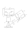
- FIG. 2 is an overall block diagram of the imaging apparatus according to Embodiment 1 of the present invention.
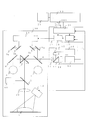
- 2 is a block diagram showing details of an irradiation configuration in FIG. 1 in the imaging apparatus according to Embodiment 1 of the present invention.
- It is a figure which shows the characteristic of the light source used for the imaging device in Embodiment 1 of this invention.
- It is a figure which shows the spatial coding method by the imaging device in Embodiment 1 of this invention.
- FIG. 10 is a block diagram showing details of the irradiation configuration of FIG. 9 in the imaging apparatus according to Embodiment 2 of the present invention. It is a figure which shows the visible and near-infrared measurement by the imaging device of Embodiment 2 of this invention. It is a whole block diagram of the imaging device in Embodiment 3 of this invention.
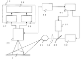
- FIG. 1 is an overall block diagram of the imaging apparatus according to Embodiment 1 of the present invention.
- FIG. 2 is a block diagram showing details of the irradiation configuration of FIG. 1 in the imaging apparatus according to Embodiment 1 of the present invention.
- FIGS. 1 and 2 will be described with reference to the characteristics of FIG. 3 to be described later.
- a three-dimensional measurement light source 40, a normal light source 2, an objective lens 30, and an illumination dichroic mirror 3 that are irradiated onto the subject 1 with respect to the microscope housing 100 are located below the main dichroic mirror 7. is set up.
- the light image of the subject 1 obtained by epi-illumination from the normal light source 2 passes through the left dichroic mirror 6 for the naked eye and the right dichroic mirror 8 for the right eye, and the left eyepiece 4 It is tied to the right eyepiece 5.
- the imaging optical axis is reflected by the main dichroic mirror 7 and then dispersed by the imaging beam splitter 11.
- visible light is imaged on the visible imaging sensor 12 and near-infrared light is imaged on the near-infrared imaging sensor 14.
- the visible light processed by the visible signal processing circuit 13 and the near infrared light processed by the near infrared signal processing circuit 16 are both sent to the synthesis processing block 19.
- the image is output to the outside through the output circuit 18 and can be viewed on an external monitor.
- the image is viewed on the eyepieces 4 and 5 via the display mirrors 9a, 9b, 9c and 9d. be able to.
- a PC general-purpose personal computer
- the output from the output circuit 18 is displayed on a PC monitor 51 connected to the PC 50. It is also possible.
- a laser controller 65 that controls the irradiation patterns of the visible laser light source 63 and the near-infrared laser light source 64 and a synchronization circuit 66 that measures the imaging timing of the imaging unit 15 are provided.
- Laser light from the two light sources is mixed by the light source MIX dichroic mirror 62, then sent to the polygon mirror 60 through the condenser lens 61, and irradiated to the subject 1 according to the rotation of the polygon mirror 60. .
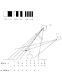
- FIG. 3 is a diagram showing the characteristics of the light source used in the imaging apparatus according to Embodiment 1 of the present invention.
- the visible laser light source 63 is irradiated with a characteristic as shown in the visible laser 73 of FIG.
- the near-infrared laser light source 64 is a laser beam having a wavelength of, for example, 900 nm that is irradiated with the characteristics shown in the near-infrared laser 74 of FIG.
- the spatial coding method is a method of encoding each point in the measurement target space with a binary code and collecting a distance image with a certain number of projections. A pattern of a predetermined light / dark pitch is projected from the light source, and the projected pattern is sequentially changed so that the light / dark pitch changes twice at a certain time interval.
- the pattern as the projection light is binary coded.
- the distance to the subject 1 can be known.
- FIG. 4 is a diagram illustrating a spatial coding method by the imaging apparatus according to Embodiment 1 of the present invention.
- a projection pattern at the point P which is the fifth region in FIG. 4 is imaged by the imaging unit 15, and the projection angle of the light source for three-dimensional measurement 40 is obtained by knowing the projection direction. For this reason, it becomes possible to know the distance.
- the surgeon first presses the start button 101 to start measurement.
- the visible laser light source 63 is driven via the laser controller 65 in order to perform visible three-dimensional measurement assuming the naked eye.
- the laser controller 65 sends an imaging start trigger to the imaging unit 15 through the synchronization circuit 66.
- the laser controller 65 projects the first projection pattern onto the subject 1 via the visible laser light source 63 and the polygon mirror 60.
- the positional relationship and the number of rotations are determined so that the pattern is projected onto the entire subject within a certain range.
- the first projection pattern image obtained from the subject 1 passes through the main dichroic mirror 7 and the imaging beam splitter 11 and forms an image on the visible imaging sensor 12.
- the formed visible signal is sent to the visible shape calculation circuit 68 in the synthesis processing block 19 via the visible signal processing circuit 13, and the control circuit 20 starts to capture data.
- the laser controller 65 and the visible laser light source 63 project the next projection pattern onto the subject 1 and, similarly, the additional data is captured by the visible shape calculation circuit 68 and the control circuit 20.
- the synchronization circuit 66 sends an end trigger to the imaging unit 15.
- the visible shape calculation circuit 68 calculates the visible distance to the subject when the capture of all projection patterns is completed.
- the result information is temporarily stored in a memory in the arithmetic circuit.
- the three-dimensional measurement in the near infrared is similarly performed. That is, an imaging start trigger is sent to the imaging unit 15 through the synchronization circuit 66, and the laser controller 65 projects the first projection pattern onto the subject 1 via the near-infrared laser light source 64 and the polygon mirror 60.
- the projection pattern image obtained from the subject 1 at this time passes through the main dichroic mirror 7 and the imaging beam splitter 11 and forms an image on the near-infrared imaging sensor 14.
- the imaged near-infrared signal is sent to the near-infrared shape calculation circuit 67 in the synthesis processing block 19 via the near-infrared signal processing circuit 16, and data capture is started in the control circuit 20. .
- the laser controller 65 and the near-infrared laser light source 64 project the next projection pattern onto the subject 1, and additional data is captured by the near-infrared shape calculation circuit 67 and the control circuit 20 in the same manner.
- the synchronization circuit 66 sends an end trigger to the imaging unit 15.
- the near-infrared shape calculation circuit 67 calculates the distance to the subject in the near-infrared at the time when all the projection patterns have been captured.
- the result information is temporarily stored in a memory in the arithmetic circuit.
- FIG. 5 is a diagram illustrating transmission of a near-infrared wavelength living body by the imaging apparatus according to Embodiment 1 of the present invention.
- FIG. 5 it is known that light in the near-infrared region is transmitted to about several millimeters under the skin in the range of 700 to 1200 nm from the absorption characteristics of hemoglobin and water in the body. Therefore, when the distance from the subject 1 is measured using a near-infrared light source, the distance up to several millimeters under the living body is measured.
- FIG. 6 is a diagram showing visible light measurement by the imaging apparatus according to Embodiment 1 of the present invention. As shown in FIG. 6, the visible light is reflected by the surface 22 of the subject 1. For this reason, when the distance is measured with visible light, the visible distance h1 is obtained.
- FIG. 7 is a diagram showing near-infrared measurement by the imaging apparatus according to Embodiment 1 of the present invention. As shown in FIG. 7, near-infrared light is reflected not on the visible surface 22 of the subject 1 in FIG.
- FIG. 8 is a diagram illustrating a three-dimensional three-dimensional expression example of the subject 1 by combining the visible and near-infrared measurement results by the imaging apparatus according to the first embodiment of the present invention.
- (a) is a three-dimensional display example of visible measurement
- (b) is a three-dimensional display example of near-infrared measurement
- (c) is a three-dimensional solid by combining both visible and near-infrared measurement results.
- the example of a display is shown and the blood vessel 21 is displayed more easily by (c).
- control circuit 20 in the system has a data interface compatible with the PC 50, and can output measurement data to the outside.
- the external PC 50 in which the dedicated software is installed can perform recalculation and data conversion for three-dimensional representation
- the PC monitor 51 has a three-dimensional structure as shown in FIG. Display can be performed.
- the near-infrared measurement three-dimensional display example (b) which is several millimeters of subcutaneous information, is combined with the visible measurement three-dimensional display example (a) and displayed as (c). It is possible to confirm and grasp the vascular tissue in the three-dimensional structure, which is very useful information from the viewpoint of confirming the situation before and after the operation.
- this application software has a function of saving this image in the PC 50, and can record and retrieve necessary information when necessary. By performing the measurement process at least once and storing the data before surgery, the surgeon can display and check images whenever necessary, including during surgery. .
- the distance measurement with the near infrared light is performed after the distance measurement with the visible light.
- the near infrared may be performed first by changing the order.
- FIGS. 1 and 2 since there are two types of light sources of visible light and near infrared, when the calculation result is rushed, visible and near It is possible to measure infrared rays simultaneously, thereby shortening the measurement time as compared with individual measurement.
- the wavelength of 600 nm was used for visible light measurement and 900 nm for near-infrared measurement, for example, another wavelength may be selected according to the sensitivity characteristics of the image sensor.
- another light source such as an LED may be used.
- the present invention is not limited to this, and even if measurement is performed with three or more types of light sources for more detailed measurement. Good. Furthermore, it is possible to reduce both of the three-dimensional measurement light source 40 and the normal light source 2 for normal observation in common.
- any pattern may be used for the pattern projection from the start to the end when performing the three-dimensional measurement by the spatial patterning method, and the number of pattern projections and the number of captured images in between are physically or If there is no time constraint, any value may be taken.
- distance measurement with the subject is used for measuring the shape of the subject, it goes without saying that methods other than distance measurement, such as a contour method, may be used as long as the shape can be measured including visible or near infrared.
- the application example to the microscope is described in the first embodiment, the present invention may be applied to a rigid endoscope, an endoscope, a macro camera, and the like.
- the method for expressing visible and near-infrared three-dimensional measurement information is not limited to a three-dimensional structure. There may be.
- Embodiment 1 described above two types of image sensors are used for visible and near-infrared, but it goes without saying that only one type is sufficient if a broadband and highly sensitive image sensor is used. Also, two or more types of image sensors may be used in order to secure a band necessary for measurement.
- the three-dimensional composite display of the distance measurement results in the visible and near infrared is performed by the external PC 50, but may be performed by the control circuit 20.
- the display method and location of the result may be any way, such as displaying on the display means inside the microscope as well as the external monitor 51.
- FIG. FIG. 9 is an overall block diagram of the imaging apparatus according to Embodiment 2 of the present invention.
- FIG. 10 is a block diagram showing details of the irradiation configuration of FIG. 9 in the imaging apparatus according to Embodiment 2 of the present invention.
- FIGS. 9 and 10 will be described with reference to the characteristics of FIG. 3 described above.
- the three-dimensional measurement light source 55 irradiating the subject 1 with respect to the microscope casing 100, the objective lens 30, and the illumination dichroic mirror 3 are installed below the main dichroic mirror 7. Further, the three-dimensional measurement light source 55 is also used for normal naked eye observation.
- the three-dimensional measurement light source 55 operates as epi-illumination in a wavelength band around 300 to 700 nm of visible light.
- This light source irradiates the subject 1 via a mirror 48 (not shown).
- a grid plate 45 used for three-dimensional measurement can be arranged between the mirror 48 and the subject 1. Actually, it is not arranged during normal observation, but has a structure in which the lattice plate 45 is manually arranged at a predetermined position in FIGS. 9 and 10 during three-dimensional measurement.
- the light image of the subject 1 obtained with this light source is connected to the left eyepiece 4 and the right eyepiece 5 through the naked eye dichroic mirror 6 and the naked eye dichroic mirror 8.
- the imaging optical axis is reflected by the main dichroic mirror 7 and then dispersed by the imaging beam splitter 11.
- visible light is imaged on the visible imaging sensor 12 and near-infrared light is imaged on the near-infrared imaging sensor 14.
- the visible light processed by the visible signal processing circuit 13 and the near infrared light processed by the near infrared signal processing circuit 16 are both sent to the synthesis processing block 19.
- the image is output to the outside through the output circuit 18 and can be viewed on an external monitor.
- the image is viewed on the eyepieces 4 and 5 via the display mirrors 9a, 9b, 9c, and 9d. be able to. It is possible to connect to a general-purpose PC 50 for the purpose of external special signal processing and video display, and the output from the output circuit 18 can be displayed on the PC monitor 51 connected to the PC 50.
- the two laser lights of the visible laser light source 63 and the near-infrared laser light source 64 are mixed by the light source MIX dichroic mirror 62 and then irradiated to the subject 1 through the lattice plate 45.
- the visible laser light source 63 is irradiated with the characteristics shown in the visible laser 73 of FIG.
- the near-infrared laser light source 64 is a laser beam having a wavelength of, for example, 900 nm that is irradiated with the characteristics shown in the near-infrared laser 74 of FIG.
- the imaging apparatus As a three-dimensional measurement method, a general moire interferometry is already used.
- the grid plate 45 is placed in front of the subject 1, illuminated by a light source, and placed at the position from the same grid plate 45 as the light source, the three-dimensional information indicating the shape of the subject 1 is used. A certain contour line stripe can be confirmed on the surface of the subject.
- the surgeon first presses the start button 101 to start measurement.
- the visible laser light source 63 and the near-infrared laser light source 64 do not need to be controlled in particular, the wavelength spectra shown in the visible laser 73 and the near-infrared laser 74 as shown in FIG. Emits light.
- the visible wavelength region that is, interference fringes that can be confirmed with the naked eye can be confirmed on the subject 1 by illumination from the visible laser light source 63.
- This light image passes through the main dichroic mirror 7 and the imaging beam splitter 11 and is formed on the visible imaging sensor 12.
- the formed visible signal is sent to the visible contour calculation circuit 71 in the synthesis processing block 19 via the visible signal processing circuit 13, where the calculation of the visible object shape is performed.
- the control circuit 20 stores the three-dimensional measurement information in the visible region, which is the result information, in the memory in the arithmetic circuit.
- the three-dimensional measurement in the near infrared is similarly performed. That is, interference fringes in the near-infrared wavelength region, that is, in a state of being transmitted to several millimeters subcutaneously can be confirmed on the subject 1 by illumination from the near-infrared laser light source 64. This light image passes through the main dichroic mirror 7 and the imaging beam splitter 11 and is formed on the near-infrared imaging sensor 14.
- the imaged near-infrared signal is sent to the near-infrared shape calculation circuit 67 in the synthesis processing block 19 via the near-infrared signal processing circuit 16, where the shape of the object in the near-infrared is measured. An operation is performed. Further, the control circuit 20 stores the three-dimensional measurement information in the near infrared region, which is the result information, in a memory in the arithmetic circuit.
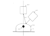
- FIG. 11 is a diagram showing visible / near infrared measurement by the imaging apparatus according to the second embodiment of the present invention.
- the visible light is reflected by the surface 22 of the subject 1 as shown in FIG.
- the contour line by the light source 55 can be confirmed on the surface of the point A and the point B, for example, depending on the positional relationship with the imaging unit 15, whereas the contour line in the near infrared is confirmed on the surface of the point C and the point D, for example. it can.
- the shape from the subject 1 is measured using the near-infrared light source using the moire interferometry, the shape can be measured up to several millimeters under the living body.
- synthesizing these two measurement data it is possible to simultaneously confirm not only the state with the naked eye but also a portion several mm below the surface. That is, since the measurement result in the near infrared is synthesized with the measurement result in the visible, not only the visual display on the surgical site, but also the image of the measurement result of the site per several millimeters of the subcutaneous can be displayed. . As a result, it is possible to display the shapes of blood vessels, lymph nodes, etc., which have not been seen until now, and the risk during surgery is suppressed.
- these two-dimensionally synthesized displays may be performed by the control circuit 20 in the system.
- the measurement data itself is three-dimensional data
- the three-dimensional structure of the subject 1 is easy to see. Is desirable. More specifically, as shown in FIG. 8 described in the first embodiment, three-dimensional stereoscopic display by combining both visible and near infrared measurement results can be performed.
- the control circuit 20 in the system has a data interface compatible with the PC 50, and can output measurement data to the outside. Then, the external PC 50 in which the dedicated software is installed can perform recalculation and data conversion for three-dimensional representation, and the PC monitor 51 has a three-dimensional structure as shown in FIG. Display can be performed.
- the near-infrared measurement three-dimensional display example (b) which is several millimeters of subcutaneous information, is combined with the visible measurement three-dimensional display example (a) and displayed as (c). It is possible to confirm and grasp the vascular tissue in the inside thereof with a three-dimensional structure, which is very useful information from the viewpoint of confirming the situation before and after the operation.
- this application software has a function of saving this image in the PC 50, and can record and retrieve necessary information when necessary. By performing the measurement process at least once and storing the data before surgery, the surgeon can display and check images whenever necessary, including during surgery. .
- the measurement with the near infrared light is performed after the measurement with the visible light, but the order may be changed and the near infrared may be performed first.
- the configuration of the second embodiment as shown in FIGS. 9 and 10, since there are two types of light sources, visible light and near infrared, when the calculation result is rushed, visible and near It is possible to measure infrared rays simultaneously, thereby shortening the measurement time as compared with individual measurement.
- the wavelength of 600 nm was used for visible light measurement and 900 nm for near-infrared measurement, for example, another wavelength may be selected in accordance with the sensitivity characteristics of the image sensor, and if interference fringes can be confirmed, Another light source such as an LED may be used instead of the laser.
- the present invention is not limited to this, and even if measurement is performed with three or more types of light sources for more detailed measurement. Good.
- a normal light source is provided individually as in the characteristics of the visible range light source 75 as shown in FIG. But you can.
- 3D measurement is performed by moire interferometry
- any other method may be adopted as long as 3D information can be obtained by image analysis.
- the application example to the microscope is described in the second embodiment, the present invention may be applied to a rigid endoscope, an endoscope, a macro camera, and the like.
- the method for expressing visible and near-infrared three-dimensional measurement information is not limited to a three-dimensional structure. There may be.
- Embodiment 2 described above two types of image sensors are used for visible and near infrared, but it goes without saying that only one type may be used if a wide-band and high-sensitivity image sensor is used. Also, two or more types of image sensors may be used in order to secure a band necessary for measurement.
- the three-dimensional composite display of the shape measurement results in the visible and near infrared is performed by the external PC 50, but may be performed by the control circuit 20.
- the display method and location of the result may be any way, such as displaying on the display means inside the microscope as well as the external monitor 51.
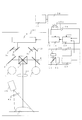
- FIG. 12 is an overall block diagram of the imaging apparatus according to Embodiment 3 of the present invention. First, FIG. 12 will be described with reference to the characteristics of FIG. 3 described above.
- the three-dimensional measurement light source 40 irradiated to the subject 1 with respect to the microscope casing 100, the normal light source 80 including excitation light, the objective lens 30, and the illumination dichroic mirror 3 are composed of the main dichroic mirror 7. It is installed on the lower side.
- the light image of the subject 1 obtained by epi-illumination from the normal light source 80 including excitation light passes through the dichroic mirror for the naked eye 6 and the right eye for the dichroic mirror 8 for the naked eye. 4 for the left part of the eye and 5 for the right part of the eyepiece.
- the imaging optical axis is reflected by the main dichroic mirror 7 and then dispersed by the imaging beam splitter 11.
- visible light is imaged on the visible imaging sensor 12 and near-infrared light is imaged on the near-infrared imaging sensor 14.
- the visible light processed by the visible signal processing circuit 13 and the near infrared light processed by the near infrared signal processing circuit 16 are both sent to the synthesis processing block 19.
- the image is output to the outside through the output circuit 18 and can be viewed on an external monitor.
- the image is viewed on the eyepieces 4 and 5 via the display mirrors 9a, 9b, 9c and 9d. be able to. It is possible to connect to a general-purpose PC 50 for the purpose of external special signal processing and video display, and the output from the output circuit 18 can be displayed on the PC monitor 51 connected to the PC 50.
- a laser controller 65 that controls the irradiation patterns of the visible laser light source 63 and the near-infrared laser light source 64 and a synchronization circuit 66 that measures the imaging timing of the imaging unit 15 are provided.
- Laser light from the two light sources is mixed by the light source MIX dichroic mirror 62, then sent to the polygon mirror 60 through the condenser lens 61, and irradiated to the subject 1 according to the rotation of the polygon mirror 60. .
- the visible laser light source 63 is irradiated with the characteristics as shown in the visible laser 73 of FIG. 3 and has a wavelength of, for example, 600 nm.
- the near-infrared laser light source 64 is a laser beam having a wavelength of, for example, 900 nm that is irradiated with the characteristics shown in the near-infrared laser 74 of FIG.
- an illumination light source including the wavelength 870 nm of the excitation light 76 in FIG. 3 is installed in the normal light source 80 including the excitation light.
- the subject 1 is administered with indocyanine green, which is a fluorescent substance for angiography, absorbs the excitation light 76 and fluoresces around about 840 nm. Therefore, an excitation light cut filter 77 is attached to the optical system of the imaging unit 15 in FIG. 12, and only a fluorescent light image can be captured from the near-infrared light image.
- the spatial coding method is a method of encoding each point in the measurement target space with a binary code and collecting a distance image with a certain number of projections. A pattern of a predetermined light / dark pitch is projected from the light source, and the projected pattern is sequentially changed so that the light / dark pitch changes twice at a certain time interval.
- the pattern as the projection light is binary coded.
- the distance to the subject 1 can be known.
- the projection pattern at the point P which is the fifth region in FIG. 4, is imaged by the imaging unit 15 and the projection direction of the light source 40 for three-dimensional measurement can be obtained by knowing the projection direction. For this reason, it becomes possible to know the distance.
- the surgeon first presses the start button 101 to start measurement.
- the visible laser light source 63 is driven via the laser controller 65 in order to perform visible three-dimensional measurement assuming the naked eye.
- the laser controller 65 sends an imaging start trigger to the imaging unit 15 through the synchronization circuit 66.
- the laser controller 65 projects the first projection pattern onto the subject 1 via the visible laser light source 63 and the polygon mirror 60.
- the positional relationship and the number of rotations are determined so that the pattern is projected onto the entire subject within a certain range.
- the first projection pattern image obtained from the subject 1 passes through the main dichroic mirror 7 and the imaging beam splitter 11 and forms an image on the visible imaging sensor 12.
- the formed visible signal is sent to the visible shape calculation circuit 68 in the synthesis processing block 19 via the visible signal processing circuit 13, and the control circuit 20 starts to capture data.
- the laser controller 65 and the visible laser light source 63 project the next projection pattern onto the subject 1 and, similarly, the additional data is captured by the visible shape calculation circuit 68 and the control circuit 20.
- the synchronization circuit 66 sends an end trigger to the imaging unit 15.
- the visible shape calculation circuit 68 calculates the visible distance to the subject when the capture of all projection patterns is completed.
- the result information is temporarily stored in a memory in the arithmetic circuit.
- the three-dimensional measurement in the near infrared is similarly performed. That is, an imaging start trigger is sent to the imaging unit 15 through the synchronization circuit 66, and the laser controller 65 projects the first projection pattern onto the subject 1 via the near-infrared laser light source 64 and the polygon mirror 60.
- the projection pattern image obtained from the subject 1 at this time passes through the main dichroic mirror 7 and the imaging beam splitter 11 and forms an image on the near-infrared imaging sensor 14.
- the imaged near-infrared signal is sent to the near-infrared shape calculation circuit 67 in the synthesis processing block 19 via the near-infrared signal processing circuit 16, and data capture is started in the control circuit 20. .
- the laser controller 65 and the near-infrared laser light source 64 project the next projection pattern onto the subject 1, and additional data is captured by the near-infrared shape calculation circuit 67 and the control circuit 20 in the same manner.
- the synchronization circuit 66 sends an end trigger to the imaging unit 15.
- the near-infrared shape calculation circuit 67 calculates the distance to the subject in the near-infrared at the time when all the projection patterns have been captured.
- the result information is temporarily stored in a memory in the arithmetic circuit.
- the fluorescence (blood vessel) portion by indocyanine green administration is collected after three-dimensional measurement by pattern projection.
- Excitation light 76 emitted from the normal light source 80 including excitation light is absorbed by incyanine green administered to the subject 1 and emits a fluorescent light image at about 840 nm. This optical image is converted into an electrical signal using the near-infrared imaging sensor 14 via the excitation light cut filter 77.
- light in the near-infrared region is the number of subcutaneous tissues in the range of 700 to 1200 nm from the absorption characteristics of hemoglobin and water in the body. It is known to transmit up to about mm. Therefore, when the distance from the subject 1 is measured using a near-infrared light source, the distance up to several millimeters under the living body is measured.
- the visible light is reflected by the surface 22 of the subject 1. For this reason, when the distance is measured by visible light, the visible distance h1 is obtained.
- near infrared light is reflected around the near-infrared surface 23 under the skin of h0 in the living body, not the visible surface 22 of the subject 1. Therefore, by synthesizing these two distance measurement data, it is possible to simultaneously confirm not only the state with the naked eye but also a part several mm subcutaneous from the surface.
- the third embodiment in order to further clarify the blood vessel, it is possible to display the fluorescence (blood vessel) portion by indocyanine green administration superimposed on the measurement result.
- these two-dimensionally synthesized displays may be performed by the control circuit 20 in the system.
- the measurement data itself is three-dimensional data
- the three-dimensional structure of the subject 1 is easy to see. Is desirable. More specifically, as shown in FIG. 8 described in the first embodiment, three-dimensional stereoscopic display by combining both visible and near infrared measurement results can be performed.
- the control circuit 20 in the system has a data interface compatible with the PC 50, and can output measurement data to the outside. Then, the external PC 50 in which the dedicated software is installed can perform recalculation and data conversion for three-dimensional representation, and the PC monitor 51 has a three-dimensional structure as shown in FIG. Display can be performed.
- the near-infrared measurement three-dimensional display example (b) which is several millimeters of subcutaneous information, is combined with the visible measurement three-dimensional display example (a) and displayed as (c). It is possible to confirm and grasp the vascular tissue in the inside thereof with a three-dimensional structure, which is very useful information from the viewpoint of confirming the situation before and after the operation.
- the blood vessel is further clearly shown by performing the synthetic display including the blood vessel clarification result by the indocyanine green phosphor, so that the operator can further understand the structure of the subject. It becomes easy.
- this application software has a function of saving the image in the PC 50, and can record and retrieve necessary information when necessary. By performing the measurement process at least once and storing the data before surgery, the surgeon can display and check images whenever necessary, including during surgery. .
- the distance measurement with the near infrared light is performed after the distance measurement with the visible light.
- the near infrared may be performed first by changing the order.
- the configuration of the third embodiment since there are two types of light sources of visible light and near infrared as shown in FIG. 12, when the calculation result is rushed, visible and near infrared are changed. Simultaneous measurement is possible, and this makes it possible to shorten the measurement time as compared with individual measurement.
- the wavelength of 600 nm was used for visible light measurement and 870 nm was used for near-infrared measurement, for example, another wavelength may be selected in accordance with the sensitivity characteristics of the image sensor.
- another light source such as an LED may be used.
- the present invention is not limited to this, and even if measurement is performed with three or more types of light sources for more detailed measurement.
- the excitation light source may be either the light source for measurement or the light source for measurement as well as the normal light source side. Furthermore, it is also possible to reduce the use of either the three-dimensional measurement light source 40 and the normal light source 80 including the excitation light for normal observation.
- any pattern may be used for the pattern projection from the start to the end when performing the three-dimensional measurement by the spatial patterning method, and the number of pattern projections and the number of captured images in between are physically or If there is no time constraint, any value may be taken.
- distance measurement with the subject is used for measuring the shape of the subject, it goes without saying that methods other than distance measurement such as the contour method may be used as long as the shape can be measured including visible or near infrared.
- the present invention may be applied to a rigid endoscope, an endoscope, a macro camera, and the like.
- the method for expressing visible and near-infrared three-dimensional measurement information is not limited to a three-dimensional structure. There may be.
- Embodiment 1 described above two types of image sensors are used for visible and near-infrared, but it goes without saying that only one type is sufficient if a broadband and highly sensitive image sensor is used. Also, two or more types of image sensors may be used in order to secure a band necessary for measurement.
- the three-dimensional composite display of the distance measurement results in the visible and near infrared is performed by the external PC 50, but may be performed by the control circuit 20.
- the display method and location of the result may be any way, such as displaying on the display means inside the microscope as well as the external monitor 51.
Landscapes
- Health & Medical Sciences (AREA)
- Life Sciences & Earth Sciences (AREA)
- Engineering & Computer Science (AREA)
- Physics & Mathematics (AREA)
- General Physics & Mathematics (AREA)
- Computer Vision & Pattern Recognition (AREA)
- Medical Informatics (AREA)
- Animal Behavior & Ethology (AREA)
- Biomedical Technology (AREA)
- Heart & Thoracic Surgery (AREA)
- Biophysics (AREA)
- Molecular Biology (AREA)
- Surgery (AREA)
- Pathology (AREA)
- General Health & Medical Sciences (AREA)
- Public Health (AREA)
- Veterinary Medicine (AREA)
- Radiology & Medical Imaging (AREA)
- Nuclear Medicine, Radiotherapy & Molecular Imaging (AREA)
- Length Measuring Devices By Optical Means (AREA)
Description
本発明は、手術時に利用される医療用カメラの分野に属し、撮像対象体の3次元画像計測を行うための撮像装置および撮像方法に関するものである。
手術など医療に使われる3次元計測装置において、紫外光や可視光、もしくは、近赤外光を用いて、複数のカメラから取得した撮像情報に基づき、人体の特定部位の3次元位置を測定する技術がある(例えば、特許文献1参照)。
しかしながら、従来技術には、以下のような課題がある。
特許文献1は、特殊プローブを利用することで、特定部位の測定に適するようになっている。このため、関係する手術部位のある程度の範囲を測定するには、不向きである。また、測定結果としての3次元情報は、あくまで肉眼で見える範囲の表面的な情報であった。
特許文献1は、特殊プローブを利用することで、特定部位の測定に適するようになっている。このため、関係する手術部位のある程度の範囲を測定するには、不向きである。また、測定結果としての3次元情報は、あくまで肉眼で見える範囲の表面的な情報であった。
たとえば、手術にて削除予定の部位の直下にリンパ節や静脈・動脈などの血管系部位が存在し、手術時にこれらをメスなどでキズ付けてはいけないような状況の場合、術者の経験と勘が頼りであり、その意味では、常にリスクが存在する。つまり、肉眼で見える範囲の表面的な情報だけでは、実際の手術には使いにくいという問題があった。
本発明は、前記のような課題を解決するためになされたものであり、手術対象である被写体の表面および内部の形状や状態を的確に確認・把握するための画像情報を提供することのできる撮像装置及び撮像方法を得ることを目的とする。
本発明に係る撮像装置は、手術対象である被写体の形状を計測するために用いられ、複数の帯域の波長を持つ光源を有する光源部と、被写体の表面および内部で反射した、光源部からの複数の帯域の計測光源光像を電気的な複数の計測撮像信号に変換する撮像部と、撮像部で変換された複数の計測撮像信号に基づき、被写体における表面の形状および内部の形状を計測する演算部と、演算部により計測された表面の形状および内部の形状を合成処理し、被写体に関する2次元画像データあるいは3次元画像データを生成する合成処理部とを備えるものである。
また、本発明に係る撮像方法は、手術対象である被写体の形状を計測するために、被写体に対して複数の帯域の波長を持つ光源を照射する光源ステップと、光源ステップでの照射により、被写体の表面および内部で反射した複数の帯域の計測光源光像を電気的な複数の計測撮像信号に変換する撮像ステップと、撮像ステップで変換された複数の計測撮像信号に基づき、被写体における表面の形状および内部の形状を計測する演算ステップと、演算ステップにより計測された表面の形状および内部の形状を合成処理し、被写体に関する2次元画像データあるいは3次元画像データを生成する合成処理ステップとを備えるものである。
本発明に係る撮像装置および撮像方法によれば、可視での計測結果と近赤外での計測結果を合成処理し、手術部位に対して肉眼表示だけでなく、皮下数ミリあたりの部位の形状測定の結果を重ねた画像情報を提供することにより、手術対象である被写体の表面および内部の形状や状態を的確に確認・把握するための画像情報を提供することのできる撮像装置及び撮像方法を得ることができる。
また、これら計測結果を被写体の3次元形状で表示することで、術者は被写体全体像をその皮下数ミリあたりの部位まで肉眼像に重ねた形で立体的に把握することができ、より高度で微細な手術への対応が可能となる。
以下、本発明の撮像装置の医療用顕微鏡としての好適な実施の形態につき図面を用いて説明する。
実施の形態1.
図1は、本発明の実施の形態1における撮像装置の全体ブロックダイヤグラムである。また、図2は、本発明の実施の形態1における撮像装置において、図1の照射構成の詳細を示すブロックダイヤグラムである。
図1は、本発明の実施の形態1における撮像装置の全体ブロックダイヤグラムである。また、図2は、本発明の実施の形態1における撮像装置において、図1の照射構成の詳細を示すブロックダイヤグラムである。
まず、図1、図2について、後述する図3の特性を参照しながら、説明する。図1では、顕微鏡筐体100に対して被写体1に照射される3次元計測用光源40と、通常光源2と、対物レンズ30と、照明用ダイクロイックミラー3が、主ダイクロイックミラー7の下側に設置されている。
また、通常の肉眼観察では、通常光源2からの落射照明にて得られた被写体1の光像は、肉眼用ダイクロイックミラー左用6と肉眼用ダイクロイックミラー右用8を通って接眼部左用4と接眼部右用5に結ばれる。一方、撮像用光軸は、主ダイクロイックミラー7で反射のうえ、撮像用ビームスプリッター11で分光される。
ここで、分光された光は、可視光が可視撮像センサー12に結像され、近赤外光が近赤外撮像センサー14に結像される。そして、可視信号処理回路13で処理された可視光と、近赤外信号処理回路16で処理された近赤外光は、ともに合成処理ブロック19へ送られる。
合成処理後は、出力回路18を通って外部へ出力され、外部モニターで映像を見ることができる。図1の例では、合成処理後の信号が顕微鏡側の映像表示装置10へ返された後、その映像を表示用ミラー9a、9b、9c、9dを介して、接眼部4、5で見ることができる。なお、外部での特殊信号処理や映像表示の目的で、汎用のパーソナルコンピュータ(以降、PCと称す)50と接続でき、出力回路18からの出力を、PC50に接続されたPCモニター51で表示することも可能である。
また、図2では、可視レーザー光源63と近赤外レーザー光源64の照射パターンを制御するレーザーコントローラ65と、撮像ユニット15との撮像タイミングを計る同期回路66とが装備されている。2つの光源からのレーザー光は、光源MIX用ダイクロイックミラー62で混合された後、集光レンズ61を介してポリゴンミラー60へ送られ、ポリゴンミラー60の回転に応じて、被写体1へ照射される。
図3は、本発明の実施の形態1における撮像装置に用いられる光源の特性を示す図である。可視レーザー光源63は、図3の可視レーザー73に示すような特性で照射された、たとえば600nmの波長のものである。また、近赤外レーザー光源64は、図3の近赤外レーザー74に示すような特性で照射された、たとえば900nmの波長のものを用いる。
次に、本実施の形態1における撮像装置の動作につき、図1と図2を用いて説明する。3次元計測方法としては、高速高精度でかつ一般的な空間コード化法を利用する。空間コード化法は、測定対象空間の各点を2進数コードで符号化し、ある投影回数で距離画像を採取する手法である。光源より所定の明暗ピッチのパターンが投影され、ある時間間隔でその明暗ピッチが倍々で変化するよう投影パターンを順次変えてゆく。
光の通過部を1、非通過部を0としてまとめることで、投影光としてのパターンが、2進コード化される。このパターン画像をカメラにて撮像し、照射時と同期をとって処理することで、被写体1との距離を知ることができる。
図4は、本発明の実施の形態1における撮像装置による空間コード化法を示す図である。たとえば、図4で5番目の領域であるP点での投影パターンを、撮像ユニット15で撮像し、投影方向を知ることで、3次元計測用光源40の投影角度が求まる。このため、距離を知ることが可能となる。
次に、実際の3次元計測動作につき説明する。術者は、まず計測開始のため、スタートボタン101を押下する。これをトリガに、肉眼を想定して可視での3次元計測を行うため、可視レーザー光源63がレーザーコントローラ65を介して駆動される。このとき、レーザーコントローラ65は、同期回路66を通じて、撮像ユニット15に撮像開始のトリガを送る。
レーザーコントローラ65は、最初の投影パターンを、可視レーザー光源63とポリゴンミラー60を介して被写体1へ投影させる。ポリゴンミラー60は、ある範囲で被写体全体に対してパターンが投影されるよう、位置関係と回転数が決められている。被写体1から得られる最初の投影パターン画像は、主ダイクロイックミラー7と撮像用ビームスプリッター11を透過し、可視撮像センサー12に結像される。
そして、結像された可視信号は、可視信号処理回路13を介して合成処理ブロック19内の可視形状演算回路68に送られ、制御回路20にてデータ取り込みが開始される。レーザーコントローラ65と可視レーザー光源63は、次の投影パターンを被写体1へ投影し、同様に、可視形状演算回路68と制御回路20にて追加データの取り込みが行われる。全ての投影パターンを同様に投影した後、同期回路66は、終了のトリガを撮像ユニット15に送る。
そして、可視形状演算回路68は、全投影パターンの取り込みが完了した時点で、可視における被写体との距離の演算を行う。結果情報は、一旦演算回路内のメモリーに格納される。
一方、近赤外での3次元計測についても、同様に実施される。すなわち、同期回路66を通じて撮像ユニット15に撮像開始のトリガが送られ、レーザーコントローラ65は、最初の投影パターンを、近赤外レーザー光源64とポリゴンミラー60を介して被写体1へ投影させる。このときの被写体1から得られる投影パターン画像は、主ダイクロイックミラー7と撮像用ビームスプリッター11を透過し、近赤外撮像センサー14に結像される。
そして、結像された近赤外信号は、近赤外信号処理回路16を介して合成処理ブロック19内の近赤外形状演算回路67に送られ、制御回路20にてデータ取り込みが開始される。レーザーコントローラ65と近赤外レーザー光源64は、次の投影パターンを、被写体1へ投影し、同様に近赤外形状演算回路67と制御回路20にて追加データの取り込みが行われる。
全ての投影パターンを同様に投影した後、同期回路66は、終了のトリガを撮像ユニット15に送る。そして、近赤外形状演算回路67は、全投影パターンの取り込みが完了した時点で、近赤外における被写体との距離の演算を行う。結果情報は、一旦演算回路内のメモリーに格納される。
図5は、本発明の実施の形態1の撮像装置による近赤外波長の生体への透過を示す図である。近赤外領域の光は、図5に示すように、体内のヘモグロビンと水分の吸収率特性から、700~1200nmあたりの範囲で生体皮下数mm程度まで透過することが知られている。従って、近赤外光源を利用して被写体1からの距離を測定した場合、生体皮下数mmあたりまでの距離を測定することになる。
図6は、本発明の実施の形態1の撮像装置による可視光測定を示す図である。図6に示すように、可視光は、被写体1の表面22で反射される。このため、可視光により距離を測定すると、可視距離h1となる。
これに対し、図7は、本発明の実施の形態1の撮像装置による近赤外測定を示す図である。図7に示すように、近赤外は、図7被写体1の可視表面22ではなく、生体でいうとh0皮下の近赤外表面23あたりで反射される。
そこで、これら2つの距離計測データを合成することで、肉眼での状態だけでなく、表面より数mm皮下の部位までも同時に確認することが可能となる。すなわち、可視での計測結果に近赤外での計測結果を合成するため、手術部位に対して肉眼表示だけでなく、皮下数ミリあたりの部位の距離測定の結果を重ねて画像表示することができる。この結果、いままで隠れて見えなかった血管・リンパ節などの表示が可能となり、手術時のリスクが抑制される。
なお、システム内の制御回路20にて2次元上にて合成されたこれらの表示を行ってもよいが、計測データ自体が3次元データのため、より見やすいように被写体1の立体的な構造での表現が望ましい。
図8は、本発明の実施の形態1の撮像装置による可視と近赤外の計測結果合成による被写体1の3次元立体表現例を示す図である。図8において、(a)は、可視計測3次元立体表示例、(b)は、近赤外計測3次元立体表示例、(c)は、可視と近赤外双方計測結果合成による3次元立体表示例を示しており、(c)により血管21をより見やすく表示している。
先の図1に示したように、システム内の制御回路20は、PC50との互換性のあるデータインターフェースを有しており、外部に計測データを出力可能となっている。そして、専用のソフトウエアがインスイトールされた外付けのPC50は、3次元表現のための再演算やデータ変換を行うことができ、PCモニター51に対して、図8のような3次元立体構造の表示を行うことが可能となる。
すなわち、可視計測3次元立体表示例(a)に対し、その数ミリ皮下の情報である近赤外計測3次元立体表示例(b)を合成して、(c)として表示することで、被写体とその内部にある血管組織を3次元構造にて確認・把握することができ、手術前後の状況確認の観点では、非常に有益な情報となる。
なお、このアプリケーションソフトは、この画像をPC50内に保存できる機能などをもっており、必要なときに必要な情報を記録したり取り出したりすることが可能である。術者は、手術前に、計測のためのプロセスを少なくとも1回実施の上、データを記憶させておくことで、手術中を含めて必要なときにいつでも画像を表示し、確認することができる。
なお、上述では、可視光での距離計測を行った後に、近赤外光での距離計測を行っているが、順番を替えて近赤外を先に行ってもよい。あるいは、本実施の形態1の構成では、先の図1、図2に示したように、可視光と近赤外の2種類の光源を持つため、演算結果を急ぐ場合には、可視と近赤外とを同時計測することが可能であり、これにより個別に行うより計測時間を短縮することができる。
また、演算後の結果表示については、可視と近赤外の両方を計測した後、合成結果を格納・表示するだけでなく、可視・近赤外それぞれの計測後に、個別に結果を格納・表示できることは言うまでもない。
また、可視光計測に600nm、近赤外計測に900nmの波長を使用したが、たとえば撮像素子の感度特性に合わせて別の波長を選んでもよく、また、パターン投影が可能であれば、レーザーでなくともLEDなど別の光源を用いてもよい。
また、計測用光源に可視光と近赤外光の2種類の光源を使用しているが、これに限らず、より詳細な計測のために、3種類以上の光源にて計測を行ってもよい。さらに、3次元計測用光源40と通常観察用の通常光源2とを共用し、いずれか一方を削減することも十分可能である。
また、空間パターン化法にて3次元計測を行う際の、開始から終了までのパターン投影は、いずれのパターンを用いてもよく、また、パターン投影回数やその間の映像取り込み枚数も、物理的もしくは時間的制約がなければ、いずれの値をとってもよい。被写体の形状測定に被写体との距離計測を利用しているが、可視もしくは近赤外含めて形状測定できるものであれば 等高線法など距離計測以外の方法を用いてもよいのは言うまでもない。さらに、本実施の形態1では、顕微鏡への適用例を説明しているが、硬性鏡や内視鏡やマクロカメラなどに適用してもよい。
また、可視と近赤外の3次元計測情報の表現手法としては、3次元立体構造に限ることなく、2次元やそのほか術者に対してわかりやすい表現手法にて表示されるのであれば、いずれであってもよい。
また、上述の実施の形態1では、可視と近赤外で2種の撮像素子を使用しているが、広帯域で感度の高い撮像センサーを採用すれば、1種で済むことは言うまでもない。また、計測に必要な帯域を確保するために、2種以上の撮像センサーを用いてもよい。
さらに、上記では、可視と近赤外での距離計測結果の3次元合成表示を外部のPC50にて行っているが、制御回路20にて行ってもよい。その際、外部のモニター51だけでなく、顕微鏡内部の表示手段へ表示するなど、結果の表示方法や場所はいずれであってもかまわない。
実施の形態2.
図9は、本発明の実施の形態2における撮像装置の全体ブロックダイヤグラムである。また、図10は、本発明の実施の形態2における撮像装置において、図9の照射構成の詳細を示すブロックダイヤグラムである。
図9は、本発明の実施の形態2における撮像装置の全体ブロックダイヤグラムである。また、図10は、本発明の実施の形態2における撮像装置において、図9の照射構成の詳細を示すブロックダイヤグラムである。
まず、図9と図10について、先述した図3の特性を参照しながら、説明する。図9では、顕微鏡筐体100に対して被写体1に照射される3次元計測用光源55と、対物レンズ30と、照明用ダイクロイックミラー3が、主ダイクロイックミラー7の下側に設置されている。また、通常の肉眼観察でも、3次元計測用光源55を使用する。
通常の観察モード時の3次元計測用光源55は、可視光300~700nmあたりの波長帯域の落射照明として動作する。この光源は、ミラー48(図示せず)を介して被写体1に照射される。ミラー48と被写体1との間には3次元計測時に使用する格子板45を配置できるようになっている。実際には、通常観察時は、配置されておらず、3次元計測時には、格子板45を手動にて、図9と図10の所定の位置に配置する構造である。
この光源にて得られた被写体1の光像は、肉眼用ダイクロイックミラー左用6と肉眼用ダイクロイックミラー右用8を通って接眼部左用4と接眼部右用5に結ばれる。一方、撮像用光軸は、主ダイクロイックミラー7で反射のうえ、撮像用ビームスプリッター11で分光される。
ここで、分光された光は、可視光が可視撮像センサー12に結像され、近赤外光が近赤外撮像センサー14に結像される。そして、可視信号処理回路13で処理された可視光と、近赤外信号処理回路16で処理された近赤外光は、ともに合成処理ブロック19へ送られる。
合成処理後は、出力回路18を通って外部へ出力され、外部モニターで映像を見ることができる。図9の例では、合成処理後の信号が顕微鏡側の映像表示装置10へ返された後、その映像を表示用ミラー9a、9b、9c、9dを介して、接眼部4、5で見ることができる。なお、外部での特殊信号処理や映像表示の目的で、汎用のPC50と接続でき、出力回路18からの出力を、PC50に接続されたPCモニター51で表示することも可能である。
また、図10では、可視レーザー光源63と近赤外レーザー光源64の2つのレーザー光は、光源MIX用ダイクロイックミラー62で混合された後、格子板45を介して被写体1へ照射される。可視レーザー光源63は、先の図3の可視レーザー73に示すような特性で照射された、たとえば600nmの波長のものである。また、近赤外レーザー光源64は、図3の近赤外レーザー74に示すような特性で照射された、たとえば900nmの波長のものを用いる。
次に、本実施の形態2における撮像装置の動作につき、図9と図10を用いて説明する。3次元計測方法としては、すでに一般的なモアレ干渉法を利用する。モアレ干渉法では、格子板45を被写体1の前面に配置し、光源にて光をあて、その光源と同じ格子板45からの位置に目を置けば、被写体1の形状を示す3次元情報である等高線縞を被写体表面上に確認することができるものである。
次に、実際の3次元計測動作につき説明する。術者は、まず計測開始のため、スタートボタン101を押下する。このとき、可視レーザー光源63と近赤外レーザー光源64は、特に制御の必要はないので、先の図3に示すような、可視レーザー73と近赤外レーザー74に示す波長スペクトルで、双方同時に発光される。
可視レーザー光源63からの照明にて被写体1上には可視波長領域、つまり、肉眼で確認可能な干渉縞が確認できる。この光像は、主ダイクロイックミラー7と撮像用ビームスプリッター11を透過し、可視撮像センサー12に結像される。
そして、結像された可視信号は、可視信号処理回路13を介して合成処理ブロック19内の可視等高演算回路71に送られ、ここで、可視における被写体の形状の演算が行われる。制御回路20により結果情報である可視領域での3次元計測情報が演算回路内のメモリーに格納される。
一方、近赤外での3次元計測についても、同様に実施される。すなわち、近赤外レーザー光源64からの照明にて被写体1上には近赤外波長領域、つまり、数mm皮下まで透過した状態での干渉縞が確認できる。この光像は、主ダイクロイックミラー7と撮像用ビームスプリッター11を透過し、近赤外撮像センサー14に結像される。
そして、結像された近赤外信号は、近赤外信号処理回路16を介して合成処理ブロック19内の近赤外形状演算回路67に送られ、ここで、近赤外における被写体の形状の演算が行われる。また、制御回路20により、結果情報である近赤外領域での3次元計測情報が演算回路内のメモリーに格納される。
ここで、近赤外領域の光は、先の図5に示したように、体内のヘモグロビンと水分の吸収率特性から、700~1200nmあたりの範囲で生体皮下数mm程度まで透過することが知られている。
図11は、本発明の実施の形態2の撮像装置による可視・近赤外測定を示す図である。可視光は、図11に示すように、被写体1の表面22で反射される。このため、撮像ユニット15との位置関係により光源55による等高線は、たとえばA点とB点の面で確認できるのに対し、近赤外での等高線は、たとえばC点とD点の面で確認できる。
このように、モアレ干渉法を用いて近赤外光源を利用し被写体1からの形状を測定した場合においても、生体皮下数mmあたりまでの形状の測定を行うことができる。この2つの計測データを合成することで、肉眼での状態だけでなく表面より数mm皮下の部位までも同時に確認することが可能となる。すなわち、可視での計測結果に近赤外での計測結果を合成するため、手術部位に対して肉眼表示だけでなく、皮下数ミリあたりの部位の測定の結果を重ねて画像表示することができる。この結果、いままで隠れて見えなかった血管・リンパ節などの形状表示が可能となり、手術時のリスクが抑制される。
なお、システム内の制御回路20にて2次元上にて合成されたこれらの表示を行ってもよいが、計測データ自体が3次元データのため、より見やすいように被写体1の立体的な構造での表現が望ましい。より具体的には、先の実施の形態1で説明した図8のように、可視と近赤外双方の計測結果合成による3次元立体表示を行うことができる。
先の図5に示したように、システム内の制御回路20は、PC50との互換性のあるデータインターフェースを有しており、外部に計測データを出力可能となっている。そして、専用のソフトウエアがインスイトールされた外付けのPC50は、3次元表現のための再演算やデータ変換を行うことができ、PCモニター51に対して、図8のような3次元立体構造の表示を行うことが可能となる。
すなわち、可視計測3次元立体表示例(a)に対し、その数ミリ皮下の情報である近赤外計測3次元立体表示例(b)を合成して、(c)として表示することで、被写体とその内部にある血管組織を3次元構造にて確認・把握することができ、手術前後の状況確認の観点では非常に有益な情報となる。
なお、このアプリケーションソフトは、この画像をPC50内に保存できる機能などをもっており、必要なときに必要な情報を記録したり取り出したりすることが可能である。術者は、手術前に、計測のためのプロセスを少なくとも1回実施の上、データを記憶させておくことで、手術中を含めて必要なときにいつでも画像を表示し、確認することができる。
なお、上述では、可視光での計測を行った後に、近赤外光での計測を行っているが、順番を替えて近赤外を先に行ってもよい。あるいは、本実施の形態2の構成では、先の図9、図10に示したように、可視光と近赤外の2種類の光源を持つため、演算結果を急ぐ場合には、可視と近赤外とを同時計測することが可能であり、これにより個別に行うより計測時間を短縮することができる。
また、演算後の結果表示については、可視と近赤外の両方を計測した後、合成結果を格納・表示するだけでなく、可視・近赤外それぞれの計測後に、個別に結果を格納・表示できることは言うまでもない。
また、可視光計測に600nm、近赤外計測に900nmの波長を使用したが、たとえば撮像素子の感度特性に合わせて別の波長を選んでもよく、また、干渉縞の確認が可能であれば、レーザーでなくともLEDなど別の光源を用いてもよい。
また、計測用光源に可視光と近赤外光の2種類の光源を使用しているが、これに限らず、より詳細な計測のために、3種類以上の光源にて計測を行ってもよい。
さらに、3次元計測用光源40と通常観察用の通常光源2とを共用しているが、先の図3に示したような可視範囲光源75の特性のように、通常光源を個別に設けることでもよい。
また、モアレ干渉法にて3次元計測を行っているが、画像解析にて3次元情報が得られるならば、ほかのいずれの手法を採用してもかまわない。さらに、本実施の形態2では、顕微鏡への適用例を説明しているが、硬性鏡や内視鏡やマクロカメラなどに適用してもよい。
また、可視と近赤外の3次元計測情報の表現手法としては、3次元立体構造に限ることなく、2次元やそのほか術者に対してわかりやすい表現手法にて表示されるのであれば、いずれであってもよい。
また、上述の実施の形態2では、可視と近赤外で2種の撮像素子を使用しているが、広帯域で感度の高い撮像センサーを採用すれば、1種で済むことは言うまでもない。また、計測に必要な帯域を確保するために、2種以上の撮像センサーを用いてもよい。
さらに、上記では、可視と近赤外での形状計測結果の3次元合成表示を外部のPC50にて行っているが、制御回路20にて行ってもよい。その際、外部のモニター51だけでなく、顕微鏡内部の表示手段へ表示するなど、結果の表示方法や場所はいずれであってもかまわない。
実施の形態3.
図12は、本発明の実施の形態3における撮像装置の全体ブロックダイヤグラムである。まず、図12について、先述した図3の特性を参照しながら、説明する。図12では、顕微鏡筐体100に対して被写体1に照射される3次元計測用光源40と、励起光を含む通常光源80と、対物レンズ30と、照明用ダイクロイックミラー3が、主ダイクロイックミラー7の下側に設置されている。
図12は、本発明の実施の形態3における撮像装置の全体ブロックダイヤグラムである。まず、図12について、先述した図3の特性を参照しながら、説明する。図12では、顕微鏡筐体100に対して被写体1に照射される3次元計測用光源40と、励起光を含む通常光源80と、対物レンズ30と、照明用ダイクロイックミラー3が、主ダイクロイックミラー7の下側に設置されている。
また、通常の肉眼観察では、励起光を含む通常光源80からの落射照明にて得られた被写体1の光像は、肉眼用ダイクロイックミラー左用6と肉眼用ダイクロイックミラー右用8を通って接眼部左用4と接眼部右用5に結ばれる。一方、撮像用光軸は、主ダイクロイックミラー7で反射のうえ、撮像用ビームスプリッター11で分光される。
ここで、分光された光は、可視光が可視撮像センサー12に結像され、近赤外光が近赤外撮像センサー14に結像される。そして、可視信号処理回路13で処理された可視光と、近赤外信号処理回路16で処理された近赤外線は、ともに合成処理ブロック19へ送られる。
合成処理後は、出力回路18を通って外部へ出力され、外部モニターで映像を見ることができる。図12の例では、合成処理後の信号が顕微鏡側の映像表示装置10へ返された後、その映像を表示用ミラー9a、9b、9c、9dを介して、接眼部4、5で見ることができる。なお、外部での特殊信号処理や映像表示の目的で、汎用のPC50と接続でき、出力回路18からの出力を、PC50に接続されたPCモニター51で表示することも可能である。
また、先の図2では、可視レーザー光源63と近赤外レーザー光源64の照射パターンを制御するレーザーコントローラ65と、撮像ユニット15との撮像タイミングを計る同期回路66とが装備されている。2つの光源からのレーザー光は、光源MIX用ダイクロイックミラー62で混合された後、集光レンズ61を介してポリゴンミラー60へ送られ、ポリゴンミラー60の回転に応じて、被写体1へ照射される。
また、可視レーザー光源63は、先の図3の可視レーザー73に示すような特性で照射された、たとえば600nmの波長のものである。また、近赤外レーザー光源64は、図3の近赤外レーザー74に示すような特性で照射された、たとえば900nmの波長のものを用いる。
また、励起光を含む通常光源80には、図3の励起光76の波長870nmを含む照明光源が設置されている。このとき、被写体1には、血管造影用蛍光物質であるインドシアニングリーンが投与され、励起光76を吸収し、約840nmあたりで蛍光する。そこで、図12の撮像ユニット15の光学系には、励起光カットフィルター77が装着されており、近赤外光像のうち、蛍光光像のみの撮像が可能である。
次に、本実施の形態3における撮像装置の動作につき、図12を用いて説明する。3次元計測方法としては、先の実施の形態1と同様に、高速高精度でかつ一般的な空間コード化法を利用する。空間コード化法は、測定対象空間の各点を2進数コードで符号化し、ある投影回数で距離画像を採取する手法である。光源より所定の明暗ピッチのパターンが投影され、ある時間間隔でその明暗ピッチが倍々で変化するよう投影パターンを順次変えてゆく。
光の通過部を1、非通過部を0としてまとめることで、投影光としてのパターンが、2進コード化される。このパターン画像をカメラにて撮像し、照射時と同期をとって処理することで、被写体1との距離を知ることができる。たとえば、先の図4で5番目の領域であるP点での投影パターンを、撮像ユニット15で撮像し、投影方向を知ることで、3次元計測用光源40の投影角度が求まる。このため、距離を知ることが可能となる。
次に、実際の3次元計測動作につき説明する。術者は、まず計測開始のため、スタートボタン101を押下する。これをトリガに、肉眼を想定して可視での3次元計測を行うため、可視レーザー光源63がレーザーコントローラ65を介して駆動される。このとき、レーザーコントローラ65は、同期回路66を通じて、撮像ユニット15に撮像開始のトリガを送る。
レーザーコントローラ65は、最初の投影パターンを、可視レーザー光源63とポリゴンミラー60を介して被写体1へ投影させる。ポリゴンミラー60は、ある範囲で被写体全体に対してパターンが投影されるよう、位置関係と回転数が決められている。被写体1から得られる最初の投影パターン画像は、主ダイクロイックミラー7と撮像用ビームスプリッター11を透過し、可視撮像センサー12に結像される。
そして、結像された可視信号は、可視信号処理回路13を介して合成処理ブロック19内の可視形状演算回路68に送られ、制御回路20にてデータ取り込みが開始される。レーザーコントローラ65と可視レーザー光源63は、次の投影パターンを被写体1へ投影し、同様に、可視形状演算回路68と制御回路20にて追加データの取り込みが行われる。全ての投影パターンを同様に投影した後、同期回路66は、終了のトリガを撮像ユニット15に送る。
そして、可視形状演算回路68は、全投影パターンの取り込みが完了した時点で、可視における被写体との距離の演算を行う。結果情報は、一旦演算回路内のメモリーに格納される。
一方、近赤外での3次元計測についても、同様に実施される。すなわち、同期回路66を通じて撮像ユニット15に撮像開始のトリガが送られ、レーザーコントローラ65は、最初の投影パターンを、近赤外レーザー光源64とポリゴンミラー60を介して被写体1へ投影させる。このときの被写体1から得られる投影パターン画像は、主ダイクロイックミラー7と撮像用ビームスプリッター11を透過し、近赤外撮像センサー14に結像される。
そして、結像された近赤外信号は、近赤外信号処理回路16を介して合成処理ブロック19内の近赤外形状演算回路67に送られ、制御回路20にてデータ取り込みが開始される。レーザーコントローラ65と近赤外レーザー光源64は、次の投影パターンを、被写体1へ投影し、同様に近赤外形状演算回路67と制御回路20にて追加データの取り込みが行われる。
全ての投影パターンを同様に投影した後、同期回路66は、終了のトリガを撮像ユニット15に送る。そして、近赤外形状演算回路67は、全投影パターンの取り込みが完了した時点で、近赤外における被写体との距離の演算を行う。結果情報は、一旦演算回路内のメモリーに格納される。
さらに、インドシアニングリーン投与による蛍光(血管)部分を、パターン投影での3次元計測後に採取する。励起光を含む通常光源80より発光された励起光76は、被写体1に投与されたインシアニングリーンに吸収され、約840nmで蛍光光像を発する。この光像は、励起光カットフィルター77を介し、近赤外撮像センサー14を用いて電気信号へ変換される。
先の実施の形態1でも述べたように、近赤外領域の光は、先の図5に示すように、体内のヘモグロビンと水分の吸収率特性から、700~1200nmあたりの範囲で生体皮下数mm程度まで透過することが知られている。従って、近赤外光源を利用して被写体1からの距離を測定した場合、生体皮下数mmあたりまでの距離を測定することになる。
先の図6に示すように、可視光は、被写体1の表面22で反射される。このため、可視光により距離を測定すると、可視距離h1となる。これに対し、先の図7に示すように、近赤外は、被写体1の可視表面22ではなく、生体でいうとh0皮下の近赤外表面23あたりで反射される。そこで、これら2つの距離計測データを合成することで、肉眼での状態だけでなく、表面より数mm皮下の部位までも同時に確認することが可能となる。
すなわち、可視での計測結果に近赤外での計測結果を合成するため、手術部位に対して肉眼表示だけでなく、皮下数ミリあたりの部位の距離測定の結果を重ねて画像表示することができる。この結果、いままで隠れて見えなかった血管・リンパ節などの表示が可能となり、手術時のリスクが抑制される。
さらに、本実施の形態3では、血管をさらに明示させるために、インドシアニングリーン投与による蛍光(血管)部分を、上記計測結果に重畳して表示を行うことを可能としている。
なお、システム内の制御回路20にて2次元上にて合成されたこれらの表示を行ってもよいが、計測データ自体が3次元データのため、より見やすいように被写体1の立体的な構造での表現が望ましい。より具体的には、先の実施の形態1で説明した図8のように、可視と近赤外双方の計測結果合成による3次元立体表示を行うことができる。
先の図12に示したように、システム内の制御回路20は、PC50との互換性のあるデータインターフェースを有しており、外部に計測データを出力可能となっている。そして、専用のソフトウエアがインスイトールされた外付けのPC50は、3次元表現のための再演算やデータ変換を行うことができ、PCモニター51に対して、図8のような3次元立体構造の表示を行うことが可能となる。
すなわち、可視計測3次元立体表示例(a)に対し、その数ミリ皮下の情報である近赤外計測3次元立体表示例(b)を合成して、(c)として表示することで、被写体とその内部にある血管組織を3次元構造にて確認・把握することができ、手術前後の状況確認の観点では非常に有益な情報となる。
このとき、本実施の形態3では、インドシアニングリーン蛍光体による、血管明示結果も含めての合成表示を行うことで、血管がさらに明示されるため、術者に対して被写体の構造がさらにわかりやすくなる。
なお、このアプリケーションソフトは、この画像をPC50内に保存できる機能などをもっており、必要なときに必要な情報を記録したり取り出したりすることが可能である。術者は、手術前に、計測のためのプロセスを少なくとも1回実施の上、データを記憶させておくことで、手術中を含めて必要なときにいつでも画像を表示し、確認することができる。
なお、上述では、可視光での距離計測を行った後に、近赤外光での距離計測を行っているが、順番を替えて近赤外を先に行ってもよい。あるいは、本実施の形態3の構成では、先の図12に示したような可視光と近赤外の2種類の光源を持つため、演算結果を急ぐ場合には、可視と近赤外とを同時計測することが可能であり、これにより個別に行うより計測時間を短縮することができる。
また、演算後の結果表示については、可視と近赤外の両方を計測した後、合成結果を格納・表示するだけでなく、可視・近赤外それぞれの計測後に、個別に結果を格納・表示できることは言うまでもない。
また、可視光計測に600nm、近赤外計測に870nmの波長を使用したが、たとえば撮像素子の感度特性に合わせて別の波長を選んでもよく、また、パターン投影が可能であれば、レーザーでなくともLEDなど別の光源を用いてもよい。
また、計測用光源に可視光と近赤外光の2種類の光源を使用しているが、これに限らず、より詳細な計測のために、3種類以上の光源にて計測を行ってもよい。励起光源は、通常光源側に配慮するのはもちろんのこと、計測用光源に配慮しても、いずれであってもよい。さらに、3次元計測用光源40と通常観察用の励起光を含む通常光源80とを共用し、いずれか一方を削減することも十分可能である。
また、空間パターン化法にて3次元計測を行う際の、開始から終了までのパターン投影は、いずれのパターンを用いてもよく、また、パターン投影回数やその間の映像取り込み枚数も、物理的もしくは時間的制約がなければ、いずれの値をとってもよい。被写体の形状測定に被写体との距離計測を利用しているが、可視もしくは近赤外含めて形状測定できるものであれば、等高線法など距離計測以外の方法を用いてもよいのは言うまでもない。さらに、本実施の形態3では、顕微鏡への適用例を説明しているが、硬性鏡や内視鏡やマクロカメラなどに適用してもよい。
また、可視と近赤外の3次元計測情報の表現手法としては、3次元立体構造に限ることなく、2次元やそのほか術者に対してわかりやすい表現手法にて表示されるのであれば、いずれであってもよい。
また、上述の実施の形態1では、可視と近赤外で2種の撮像素子を使用しているが、広帯域で感度の高い撮像センサーを採用すれば、1種で済むことは言うまでもない。また、計測に必要な帯域を確保するために、2種以上の撮像センサーを用いてもよい。
さらに、上記では、可視と近赤外での距離計測結果の3次元合成表示を外部のPC50にて行っているが、制御回路20にて行ってもよい。その際、外部のモニター51だけでなく、顕微鏡内部の表示手段へ表示するなど、結果の表示方法や場所はいずれであってもかまわない。
Claims (6)
- 手術対象である被写体の形状を計測するために用いられ、複数の帯域の波長を持つ光源を有する光源部と、
前記被写体の表面および内部で反射した、前記光源部からの複数の帯域の計測光源光像を電気的な複数の計測撮像信号に変換する撮像部と、
前記撮像部で変換された前記複数の計測撮像信号に基づき、前記被写体における前記表面の形状および前記内部の形状を計測する演算部と、
前記演算部により計測された前記表面の形状および前記内部の形状を合成処理し、前記被写体に関する2次元画像データあるいは3次元画像データを生成する合成処理部と
を備えることを特徴とする撮像装置。 - 請求項1に記載の撮像装置において、
前記撮像部は、
前記被写体の前記表面で反射した、前記光源部からの計測光源光像のうち第一の波長帯域の光像を電気的な計測撮像信号に変換する第一の撮像部と、
前記被写体の前記内部で反射した、前記光源部からの計測光源光像のうち第二の波長帯域の光像を電気的な計測撮像信号に変換する第二の撮像部と
を有し、
前記演算部は、
前記第一の撮像部で変換された計測撮像信号に基づき、前記被写体における前記表面までの第一の形状を計測する第一の演算部と、
前記第二の撮像部で変換された計測撮像信号に基づき、前記被写体における前記内部までの第二の形状を計測する第二の演算部と
を有し、
前記合成部は、前記第一の演算部で計測された前記第一の形状と、前記第二の演算部で計測された前記第二の形状とを合成処理し、前記2次元画像データあるいは前記3次元画像データを生成する
ことを特徴とする撮像装置。 - 請求項2に記載の撮像装置において、
前記第二の撮像部は、前記被写体に対して血管造影用蛍光物質が投与されている場合に、励起光をカットする手段を介して取得した蛍光光像を電気的な計測撮像信号に変換する
ことを特徴とする撮像装置。 - 請求項1ないし3のいずれか1項に記載の撮像装置において、
前記光源部と前記演算部は、空間コード化法による距離計測法を適用する
ことを特徴とする撮像装置。 - 請求項1ないし3のいずれか1項に記載の撮像装置において、
前記光源部と前記演算部は、モアレ干渉法を適用する
ことを特徴とする撮像装置。 - 手術対象である被写体の形状を計測するために、前記被写体に対して複数の帯域の波長を持つ光源を照射する光源ステップと、
前記光源ステップでの前記照射により、前記被写体の表面および内部で反射した複数の帯域の計測光源光像を電気的な複数の計測撮像信号に変換する撮像ステップと、
前記撮像ステップで変換された前記複数の計測撮像信号に基づき、前記被写体における前記表面の形状および前記内部の形状を計測する演算ステップと、
前記演算ステップにより計測された前記表面の形状および前記内部の形状を合成処理し、前記被写体に関する2次元画像データあるいは3次元画像データを生成する合成処理ステップと
を備えることを特徴とする撮像方法。
Priority Applications (3)
| Application Number | Priority Date | Filing Date | Title |
|---|---|---|---|
| CN201380025798.9A CN104364606A (zh) | 2012-05-24 | 2013-03-05 | 摄像装置和摄像方法 |
| US14/402,947 US9746318B2 (en) | 2012-05-24 | 2013-03-05 | Imaging apparatus and imaging method |
| EP13793242.2A EP2857793B1 (en) | 2012-05-24 | 2013-03-05 | Image capture device and image capture method |
Applications Claiming Priority (2)
| Application Number | Priority Date | Filing Date | Title |
|---|---|---|---|
| JP2012-118343 | 2012-05-24 | ||
| JP2012118343A JP5930531B2 (ja) | 2012-05-24 | 2012-05-24 | 撮像装置および撮像方法 |
Publications (1)
| Publication Number | Publication Date |
|---|---|
| WO2013175827A1 true WO2013175827A1 (ja) | 2013-11-28 |
Family
ID=49623531
Family Applications (1)
| Application Number | Title | Priority Date | Filing Date |
|---|---|---|---|
| PCT/JP2013/055962 Ceased WO2013175827A1 (ja) | 2012-05-24 | 2013-03-05 | 撮像装置および撮像方法 |
Country Status (5)
| Country | Link |
|---|---|
| US (1) | US9746318B2 (ja) |
| EP (1) | EP2857793B1 (ja) |
| JP (1) | JP5930531B2 (ja) |
| CN (1) | CN104364606A (ja) |
| WO (1) | WO2013175827A1 (ja) |
Cited By (2)
| Publication number | Priority date | Publication date | Assignee | Title |
|---|---|---|---|---|
| CN105890545A (zh) * | 2015-01-26 | 2016-08-24 | 德律科技股份有限公司 | 光学检测系统 |
| CN111789608A (zh) * | 2020-08-10 | 2020-10-20 | 上海联影医疗科技有限公司 | 一种成像系统和方法 |
Families Citing this family (15)
| Publication number | Priority date | Publication date | Assignee | Title |
|---|---|---|---|---|
| EP2925227B1 (en) | 2012-11-27 | 2018-03-28 | Pneumacare Ltd | Analysis of breathing data |
| WO2015098288A1 (ja) * | 2013-12-27 | 2015-07-02 | ソニー株式会社 | 画像処理装置、および画像処理方法 |
| CN112932416A (zh) * | 2015-06-04 | 2021-06-11 | 松下知识产权经营株式会社 | 生物体信息检测装置及生物体信息检测方法 |
| KR102464368B1 (ko) * | 2017-11-07 | 2022-11-07 | 삼성전자주식회사 | 메타 프로젝터 및 이를 포함하는 전자 장치 |
| ES2659089A1 (es) * | 2017-11-23 | 2018-03-13 | Fundación Instituto De Investigación Sanitaria Fundación Jimenez-Díaz | Dispositivo y procedimiento de obtención de medidas mecánicas, geométricas y dinámicas de superficies ópticas |
| JP7022661B2 (ja) * | 2018-06-28 | 2022-02-18 | 株式会社Screenホールディングス | 形状測定装置および形状測定方法 |
| EP3824621B1 (en) | 2018-07-19 | 2025-06-11 | Activ Surgical, Inc. | Systems and methods for multi-modal sensing of depth in vision systems for automated surgical robots |
| EP3879226B1 (en) | 2018-11-08 | 2023-01-04 | Chengdu Pin Tai Ding Feng Business Administration | Three-dimensional measurement device |
| EP3902458A4 (en) | 2018-12-28 | 2022-09-21 | Activ Surgical, Inc. | USER INTERFACE ELEMENTS TO ALIGN A REMOTE CAMERA DURING OPERATIONS |
| JP2022516473A (ja) | 2018-12-28 | 2022-02-28 | アクティブ サージカル, インコーポレイテッド | 低侵襲性外科手術における到達性、作業空間、および巧妙さを最適化するためのシステムおよび方法 |
| US12292564B2 (en) | 2019-04-08 | 2025-05-06 | Activ Surgical, Inc. | Systems and methods for medical imaging |
| WO2020210168A1 (en) | 2019-04-08 | 2020-10-15 | Activ Surgical, Inc. | Systems and methods for medical imaging |
| WO2020214821A1 (en) | 2019-04-19 | 2020-10-22 | Activ Surgical, Inc. | Systems and methods for trocar kinematics |
| JP7354608B2 (ja) * | 2019-06-21 | 2023-10-03 | ソニーグループ株式会社 | 医療用観察システム、医療用観察方法、および情報処理装置 |
| EP4017340A4 (en) | 2019-08-21 | 2023-12-13 | Activ Surgical, Inc. | Systems and methods for medical imaging |
Citations (6)
| Publication number | Priority date | Publication date | Assignee | Title |
|---|---|---|---|---|
| JP3152810B2 (ja) | 1993-07-15 | 2001-04-03 | 瑞穂医科工業株式会社 | 光学式3次元位置検出装置 |
| JP2006098340A (ja) * | 2004-09-30 | 2006-04-13 | Sharp Corp | 内部検出装置 |
| JP2006130201A (ja) * | 2004-11-09 | 2006-05-25 | Matsushita Electric Ind Co Ltd | 血管及び注射針位置提示装置、及び血管及び注射針位置提示方法 |
| JP2006177781A (ja) * | 2004-12-22 | 2006-07-06 | Matsushita Electric Works Ltd | 3次元形状計測方法並びに3次元形状計測装置、3次元形状計測用プログラム |
| JP2010000218A (ja) * | 2008-06-20 | 2010-01-07 | Terumo Corp | 静脈表示装置 |
| JP2010220669A (ja) * | 2009-03-19 | 2010-10-07 | Fujifilm Corp | 光立体構造計測装置及びその構造情報処理方法 |
Family Cites Families (8)
| Publication number | Priority date | Publication date | Assignee | Title |
|---|---|---|---|---|
| JP3807721B2 (ja) * | 2000-02-21 | 2006-08-09 | シャープ株式会社 | 画像合成装置 |
| JP2003075137A (ja) * | 2001-09-04 | 2003-03-12 | Minolta Co Ltd | 撮影システム並びにそれに用いられる撮像装置および3次元計測用補助ユニット |
| KR100752758B1 (ko) * | 2005-10-19 | 2007-08-29 | (주) 인텍플러스 | 영상 측정 장치 및 그 방법 |
| US8731367B2 (en) * | 2006-03-01 | 2014-05-20 | Kabushiki Kaisha Toshiba | Image processing apparatus |
| CN104398240B (zh) * | 2007-06-25 | 2017-06-20 | 真实成像有限公司 | 用于分析图像的方法、装置和系统 |
| JP5298265B2 (ja) * | 2008-03-24 | 2013-09-25 | 三菱電機株式会社 | 患者位置決め装置 |
| JP2010093472A (ja) | 2008-10-07 | 2010-04-22 | Panasonic Corp | 撮像装置および撮像装置用信号処理回路 |
| CN102319059B (zh) * | 2011-10-28 | 2013-03-27 | 北京天助基业科技发展有限公司 | 近红外荧光造影手术引导装置及其应用 |
-
2012
- 2012-05-24 JP JP2012118343A patent/JP5930531B2/ja not_active Expired - Fee Related
-
2013
- 2013-03-05 US US14/402,947 patent/US9746318B2/en active Active
- 2013-03-05 EP EP13793242.2A patent/EP2857793B1/en active Active
- 2013-03-05 WO PCT/JP2013/055962 patent/WO2013175827A1/ja not_active Ceased
- 2013-03-05 CN CN201380025798.9A patent/CN104364606A/zh active Pending
Patent Citations (6)
| Publication number | Priority date | Publication date | Assignee | Title |
|---|---|---|---|---|
| JP3152810B2 (ja) | 1993-07-15 | 2001-04-03 | 瑞穂医科工業株式会社 | 光学式3次元位置検出装置 |
| JP2006098340A (ja) * | 2004-09-30 | 2006-04-13 | Sharp Corp | 内部検出装置 |
| JP2006130201A (ja) * | 2004-11-09 | 2006-05-25 | Matsushita Electric Ind Co Ltd | 血管及び注射針位置提示装置、及び血管及び注射針位置提示方法 |
| JP2006177781A (ja) * | 2004-12-22 | 2006-07-06 | Matsushita Electric Works Ltd | 3次元形状計測方法並びに3次元形状計測装置、3次元形状計測用プログラム |
| JP2010000218A (ja) * | 2008-06-20 | 2010-01-07 | Terumo Corp | 静脈表示装置 |
| JP2010220669A (ja) * | 2009-03-19 | 2010-10-07 | Fujifilm Corp | 光立体構造計測装置及びその構造情報処理方法 |
Non-Patent Citations (1)
| Title |
|---|
| See also references of EP2857793A4 * |
Cited By (3)
| Publication number | Priority date | Publication date | Assignee | Title |
|---|---|---|---|---|
| CN105890545A (zh) * | 2015-01-26 | 2016-08-24 | 德律科技股份有限公司 | 光学检测系统 |
| CN111789608A (zh) * | 2020-08-10 | 2020-10-20 | 上海联影医疗科技有限公司 | 一种成像系统和方法 |
| CN111789608B (zh) * | 2020-08-10 | 2023-09-19 | 上海联影医疗科技股份有限公司 | 一种成像系统和方法 |
Also Published As
| Publication number | Publication date |
|---|---|
| US20150145987A1 (en) | 2015-05-28 |
| EP2857793A4 (en) | 2016-01-06 |
| EP2857793A1 (en) | 2015-04-08 |
| JP5930531B2 (ja) | 2016-06-08 |
| US9746318B2 (en) | 2017-08-29 |
| CN104364606A (zh) | 2015-02-18 |
| EP2857793B1 (en) | 2019-12-11 |
| JP2013245980A (ja) | 2013-12-09 |
Similar Documents
| Publication | Publication Date | Title |
|---|---|---|
| JP5930531B2 (ja) | 撮像装置および撮像方法 | |
| US12166953B2 (en) | Optical imaging system and methods thereof | |
| US7823782B2 (en) | Dental optical coherence tomograph | |
| JP5856610B2 (ja) | カラー光学印象による経時的三次元測定装置 | |
| EP1685795A1 (en) | Apparatus for acquiring tomographic image formed by ultrasound-modulated fluorescence | |
| EP4014846B1 (en) | Tomography convergence-type oral scanner | |
| JP2010509993A (ja) | 歯牙撮像用oct装置 | |
| JP2009041946A (ja) | 光画像計測装置 | |
| JP2008194108A (ja) | 位置方向検出機能付き3次元上特性測定・表示装置 | |
| US20090021745A1 (en) | Optical Coherence Tomography Device and Measuring Head | |
| JP5062816B2 (ja) | 反射型断層撮影装置 | |
| KR101615370B1 (ko) | 치아 법랑질의 부피 측정 시스템 및 그 방법 | |
| JP2010051390A (ja) | 光断層画像取得装置及び光断層画像取得方法 | |
| JP2008194107A (ja) | 歯科用3次元上特性測定・表示装置 | |
| TWI342201B (ja) | ||
| JP5144579B2 (ja) | 眼科観察装置 | |
| JP2010046216A (ja) | 光断層画像取得装置及び光断層画像取得方法 | |
| KR101594523B1 (ko) | 가시광 광학영상 및 비가시광 형광영상의 동시구현이 가능한 광대역 영상 획득투사장치 | |
| CN201234971Y (zh) | 基于振幅型透射光栅投影的三维内窥测量装置 | |
| JP2012010776A (ja) | 断層画像処理装置及び方法、並びに光干渉断層画像診断装置 | |
| EP4230119A1 (en) | Intraoral scanner having tomographic imaging function and method for detecting cracks in oral structures using the same | |
| JP2009006155A (ja) | 歯科光診断装置 | |
| JP4109132B2 (ja) | 蛍光判定装置 | |
| CN219895706U (zh) | 一种甲状旁腺功能成像系统及内镜 | |
| WO2012014920A1 (ja) | 光断層画像化装置および光断層画像化方法 |
Legal Events
| Date | Code | Title | Description |
|---|---|---|---|
| 121 | Ep: the epo has been informed by wipo that ep was designated in this application |
Ref document number: 13793242 Country of ref document: EP Kind code of ref document: A1 |
|
| WWE | Wipo information: entry into national phase |
Ref document number: 2013793242 Country of ref document: EP |
|
| WWE | Wipo information: entry into national phase |
Ref document number: 14402947 Country of ref document: US |
|
| NENP | Non-entry into the national phase |
Ref country code: DE |