WO2013176060A1 - 排ガス処理装置 - Google Patents
排ガス処理装置 Download PDFInfo
- Publication number
- WO2013176060A1 WO2013176060A1 PCT/JP2013/063828 JP2013063828W WO2013176060A1 WO 2013176060 A1 WO2013176060 A1 WO 2013176060A1 JP 2013063828 W JP2013063828 W JP 2013063828W WO 2013176060 A1 WO2013176060 A1 WO 2013176060A1
- Authority
- WO
- WIPO (PCT)
- Prior art keywords
- exhaust gas
- desulfurization
- denitration
- treatment apparatus
- downstream side
- Prior art date
- Legal status (The legal status is an assumption and is not a legal conclusion. Google has not performed a legal analysis and makes no representation as to the accuracy of the status listed.)
- Ceased
Links
Images

Classifications
-
- B—PERFORMING OPERATIONS; TRANSPORTING
- B01—PHYSICAL OR CHEMICAL PROCESSES OR APPARATUS IN GENERAL
- B01D—SEPARATION
- B01D53/00—Separation of gases or vapours; Recovering vapours of volatile solvents from gases; Chemical or biological purification of waste gases, e.g. engine exhaust gases, smoke, fumes, flue gases, aerosols
- B01D53/34—Chemical or biological purification of waste gases
- B01D53/46—Removing components of defined structure
- B01D53/60—Simultaneously removing sulfur oxides and nitrogen oxides
-
- B—PERFORMING OPERATIONS; TRANSPORTING
- B01—PHYSICAL OR CHEMICAL PROCESSES OR APPARATUS IN GENERAL
- B01D—SEPARATION
- B01D53/00—Separation of gases or vapours; Recovering vapours of volatile solvents from gases; Chemical or biological purification of waste gases, e.g. engine exhaust gases, smoke, fumes, flue gases, aerosols
- B01D53/34—Chemical or biological purification of waste gases
- B01D53/74—General processes for purification of waste gases; Apparatus or devices specially adapted therefor
- B01D53/77—Liquid phase processes
- B01D53/78—Liquid phase processes with gas-liquid contact
-
- B—PERFORMING OPERATIONS; TRANSPORTING
- B01—PHYSICAL OR CHEMICAL PROCESSES OR APPARATUS IN GENERAL
- B01D—SEPARATION
- B01D53/00—Separation of gases or vapours; Recovering vapours of volatile solvents from gases; Chemical or biological purification of waste gases, e.g. engine exhaust gases, smoke, fumes, flue gases, aerosols
- B01D53/34—Chemical or biological purification of waste gases
- B01D53/46—Removing components of defined structure
- B01D53/48—Sulfur compounds
- B01D53/50—Sulfur oxides
- B01D53/501—Sulfur oxides by treating the gases with a solution or a suspension of an alkali or earth-alkali or ammonium compound
- B01D53/504—Sulfur oxides by treating the gases with a solution or a suspension of an alkali or earth-alkali or ammonium compound characterised by a specific device
-
- B—PERFORMING OPERATIONS; TRANSPORTING
- B01—PHYSICAL OR CHEMICAL PROCESSES OR APPARATUS IN GENERAL
- B01D—SEPARATION
- B01D53/00—Separation of gases or vapours; Recovering vapours of volatile solvents from gases; Chemical or biological purification of waste gases, e.g. engine exhaust gases, smoke, fumes, flue gases, aerosols
- B01D53/34—Chemical or biological purification of waste gases
- B01D53/46—Removing components of defined structure
- B01D53/48—Sulfur compounds
- B01D53/50—Sulfur oxides
- B01D53/507—Sulfur oxides by treating the gases with other liquids
-
- B—PERFORMING OPERATIONS; TRANSPORTING
- B01—PHYSICAL OR CHEMICAL PROCESSES OR APPARATUS IN GENERAL
- B01D—SEPARATION
- B01D53/00—Separation of gases or vapours; Recovering vapours of volatile solvents from gases; Chemical or biological purification of waste gases, e.g. engine exhaust gases, smoke, fumes, flue gases, aerosols
- B01D53/34—Chemical or biological purification of waste gases
- B01D53/46—Removing components of defined structure
- B01D53/54—Nitrogen compounds
- B01D53/56—Nitrogen oxides
-
- B—PERFORMING OPERATIONS; TRANSPORTING
- B01—PHYSICAL OR CHEMICAL PROCESSES OR APPARATUS IN GENERAL
- B01D—SEPARATION
- B01D53/00—Separation of gases or vapours; Recovering vapours of volatile solvents from gases; Chemical or biological purification of waste gases, e.g. engine exhaust gases, smoke, fumes, flue gases, aerosols
- B01D53/34—Chemical or biological purification of waste gases
- B01D53/46—Removing components of defined structure
- B01D53/62—Carbon oxides
-
- B—PERFORMING OPERATIONS; TRANSPORTING
- B01—PHYSICAL OR CHEMICAL PROCESSES OR APPARATUS IN GENERAL
- B01D—SEPARATION
- B01D53/00—Separation of gases or vapours; Recovering vapours of volatile solvents from gases; Chemical or biological purification of waste gases, e.g. engine exhaust gases, smoke, fumes, flue gases, aerosols
- B01D53/34—Chemical or biological purification of waste gases
- B01D53/74—General processes for purification of waste gases; Apparatus or devices specially adapted therefor
- B01D53/75—Multi-step processes
-
- B—PERFORMING OPERATIONS; TRANSPORTING
- B01—PHYSICAL OR CHEMICAL PROCESSES OR APPARATUS IN GENERAL
- B01D—SEPARATION
- B01D2251/00—Reactants
- B01D2251/30—Alkali metal compounds
- B01D2251/304—Alkali metal compounds of sodium
-
- B—PERFORMING OPERATIONS; TRANSPORTING
- B01—PHYSICAL OR CHEMICAL PROCESSES OR APPARATUS IN GENERAL
- B01D—SEPARATION
- B01D2251/00—Reactants
- B01D2251/50—Inorganic acids
-
- B—PERFORMING OPERATIONS; TRANSPORTING
- B01—PHYSICAL OR CHEMICAL PROCESSES OR APPARATUS IN GENERAL
- B01D—SEPARATION
- B01D2258/00—Sources of waste gases
- B01D2258/02—Other waste gases
- B01D2258/0283—Flue gases
-
- B—PERFORMING OPERATIONS; TRANSPORTING
- B01—PHYSICAL OR CHEMICAL PROCESSES OR APPARATUS IN GENERAL
- B01D—SEPARATION
- B01D53/00—Separation of gases or vapours; Recovering vapours of volatile solvents from gases; Chemical or biological purification of waste gases, e.g. engine exhaust gases, smoke, fumes, flue gases, aerosols
- B01D53/34—Chemical or biological purification of waste gases
- B01D53/46—Removing components of defined structure
- B01D53/48—Sulfur compounds
- B01D53/50—Sulfur oxides
-
- Y—GENERAL TAGGING OF NEW TECHNOLOGICAL DEVELOPMENTS; GENERAL TAGGING OF CROSS-SECTIONAL TECHNOLOGIES SPANNING OVER SEVERAL SECTIONS OF THE IPC; TECHNICAL SUBJECTS COVERED BY FORMER USPC CROSS-REFERENCE ART COLLECTIONS [XRACs] AND DIGESTS
- Y02—TECHNOLOGIES OR APPLICATIONS FOR MITIGATION OR ADAPTATION AGAINST CLIMATE CHANGE
- Y02A—TECHNOLOGIES FOR ADAPTATION TO CLIMATE CHANGE
- Y02A50/00—TECHNOLOGIES FOR ADAPTATION TO CLIMATE CHANGE in human health protection, e.g. against extreme weather
- Y02A50/20—Air quality improvement or preservation, e.g. vehicle emission control or emission reduction by using catalytic converters
-
- Y—GENERAL TAGGING OF NEW TECHNOLOGICAL DEVELOPMENTS; GENERAL TAGGING OF CROSS-SECTIONAL TECHNOLOGIES SPANNING OVER SEVERAL SECTIONS OF THE IPC; TECHNICAL SUBJECTS COVERED BY FORMER USPC CROSS-REFERENCE ART COLLECTIONS [XRACs] AND DIGESTS
- Y02—TECHNOLOGIES OR APPLICATIONS FOR MITIGATION OR ADAPTATION AGAINST CLIMATE CHANGE
- Y02C—CAPTURE, STORAGE, SEQUESTRATION OR DISPOSAL OF GREENHOUSE GASES [GHG]
- Y02C20/00—Capture or disposal of greenhouse gases
- Y02C20/40—Capture or disposal of greenhouse gases of CO2
Definitions
- the present invention provides a pretreatment for recovering CO 2 removal in the flue gas, to an exhaust gas treatment apparatus that suppresses deterioration of the CO 2 absorbing solution.
- the greenhouse effect due to CO 2 contained in the exhaust gas from the boiler has been pointed out, and countermeasures have become urgent internationally in order to protect the global environment.
- the source of CO 2 extends to all human activity fields where fossil fuels are burned, and there is a tendency to further demand for emission control.
- the boiler exhaust gas is brought into contact with an amine-based absorbent such as an amine compound aqueous solution to remove and recover CO 2 in the exhaust gas.
- the method is energetically studied.
- CO 2 absorbing liquid to absorb the CO 2 are the amine compounds, due to the accumulation of resulting substances by NO 2 and SO 2 caused in the exhaust gas, the deterioration and the life of the absorbent is a problem.
- Patent Document 1 proposes for reducing the SO 2 concentration in the exhaust gas from the coal fired boiler and the NO 2 concentration in the natural gas combustion exhaust gas (Patent Document 1 and Patent Document 2).
- Patent Documents 1 and 2 there is a proposal to highly desulfurize so that the sulfur oxide concentration becomes 1 ppm, but in recent years it has been required to further reduce the SO 2 concentration (for example, 0.1 ppm or less). It has been.
- the proposal in Patent Document 2 there is a proposal to perform advanced denitration so that the nitrogen dioxide concentration becomes 3 ppm, but the NO 2 concentration can be further reduced (for example, preferably 0.2 ppm or less at the outlet). It has been demanded in recent years.
- a first invention of the present invention for solving the above-described problems is a denitration apparatus that removes nitrogen oxides from exhaust gas containing nitrogen oxides, sulfur oxides, and carbon dioxide to an extremely low concentration. And a desulfurization device installed on the downstream side of the gas flow of the denitration device and removing sulfur oxides in the exhaust gas to an extremely low concentration, and installed on the downstream side of the gas flow of the desulfurization device and remaining in the exhaust gas.
- An exhaust gas treatment apparatus comprising a carbon dioxide recovery device that removes and recovers carbon dioxide in exhaust gas.
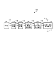
- the second invention is characterized in that, in the first invention, the SO 2 alkali removing device is installed on the downstream side of the gas flow of the finish denitration / desulfurization device and removes residual SO 2 in the exhaust gas with alkali. In the exhaust gas treatment device.
- an exhaust gas treatment apparatus according to the second aspect of the invention, further comprising a gas cooling device that is installed on the downstream side of the gas flow of the SO 2 alkali removal device and cools the exhaust gas.
- the finish denitration / desulfurization device and the SO 2 alkali removal device installed above the downstream side of the gas flow are integrally disposed in the tower.
- the waste gas processing apparatus characterized by this.
- an exhaust gas treatment apparatus according to the fourth aspect of the present invention, wherein a gas cooling device is disposed above the downstream side of the SO 2 alkali removal device.
- a sixth invention is an exhaust gas treatment apparatus according to any one of the second to fifth inventions, wherein an oxidant is introduced into the SO 2 alkali removal apparatus.
- a seventh invention is an exhaust gas treatment apparatus according to any one of the second to sixth inventions, wherein surplus water of the SO 2 alkali removal device is introduced into a finishing denitration / desulfurization device.
- An eighth aspect of the invention is an exhaust gas treatment apparatus according to any one of the second to seventh aspects of the invention, wherein surplus water of the gas cooling device is introduced into an SO 2 alkali removal device.
- an extremely low concentration (for example, 1 ppm or less) of NO 2 and a very low concentration (for example, 50 ppm or less) of SO 2 remaining in the exhaust gas are further obtained using an absorbent containing sulfite. It is possible to remove and finish denitration / desulfurization to 0.1 ppm or less. Thereby, accumulation
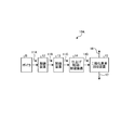
- FIG. 1 is a schematic diagram of an exhaust gas treatment apparatus according to a first embodiment.
- FIG. 2 is a schematic diagram of another exhaust gas treatment apparatus according to the first embodiment.
- FIG. 3 is a schematic diagram of another exhaust gas treatment apparatus according to the first embodiment.
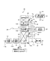
- FIG. 4 is a schematic diagram of an exhaust gas treatment apparatus according to the second embodiment.
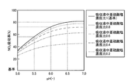
- FIG. 5 is a graph showing the relationship between pH and NO 2 absorption rate when the concentration of sulfite in the absorbing solution is changed.
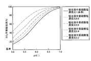
- FIG. 6 is a graph showing the relationship between pH and SO 2 equilibrium absorption rate when the concentration of sulfite in the absorbing solution is changed.
- FIG. 1 is a schematic diagram of an exhaust gas treatment apparatus according to a first embodiment.
- 2 and 3 are schematic views of another exhaust gas treatment apparatus according to the first embodiment.
- the exhaust gas treatment apparatus 10A according to the present embodiment is exhausted from, for example, a boiler B, and nitrogen oxides are exhausted from an exhaust gas 11A containing nitrogen oxides, sulfur oxides, and carbon dioxide to an extremely low concentration.
- reference numeral 16 indicates purified gas
- 17 indicates recovered CO 2 .
- NO 2 in the exhaust gas 11A is denitrated to an extremely low concentration (for example, 1 ppm or less) by a denitration device 12 that is generally installed.
- a denitration device 12 is an ammonia denitration device.
- the desulfurization apparatus 13 desulfurizes the SO 2 concentration in the exhaust gas 11B after denitration to an extremely low concentration (for example, 50 ppm or less).
- an extremely low concentration for example, 50 ppm or less.
- the desulfurization device 13 a desulfurization device of a wet lime / gypsum method can be exemplified.
- the NO 2 concentration and the SO 2 concentration in the exhaust gas 11C are finished and removed to an extremely low concentration (0.1 ppm or less) using an absorbing solution containing sulfite.
- the performance deterioration of the absorbent used in the carbon dioxide recovery device 15 can be suppressed by finishing and removing the SO 2 concentration to an extremely low concentration (0.1 ppm or less).
- the frequency of the reclaiming operation (cleaning operation) of the absorbing liquid which is an operation for preventing the deterioration of the absorbing liquid, can be reduced as compared with the conventional method.
- the frequency of the cleaning operation can be halved.
- the SO 2 concentration is 1 ppm, the cleaning operation is required once every 40 days. However, when the SO 2 concentration is 0.1 ppm, the cleaning operation once every 80 days is sufficient.
- the absorption liquid containing sulfite used in the finishing denitration / desulfurization apparatus 14 uses SO 2 contained in the exhaust gas 11C, so that it is not necessary to supply a chemical from outside.
- SO 2 contained in the exhaust gas 11C
- FIG. 5 is a graph showing the relationship between pH and NO 2 absorption rate when the concentration of sulfite in the absorbing solution is changed.
- FIG. 6 is a graph showing the relationship between pH and SO 2 equilibrium absorption rate when the concentration of sulfite in the absorbing solution is changed.
- the standard sulfurous acid concentration is 63 mmol / L. This is because the reference sulfite concentration in the figure is 5.5 t / hr for the waste water from the finishing denitration / desulfurization cooling tower when the exhaust gas quantity at the inlet is 700,000 Nm 3 / hr and the SO 2 concentration is 14 ppm. This is the concentration of sulfurous acid corresponding to the case where the absorbed SO 2 was not oxidized at all.
- the pH and the sulfurous acid concentration are set in order to extremely reduce the NO 2 and SO 2 concentrations remaining in the exhaust gas.
- the pH in the finishing denitration / desulfurization apparatus 14 is preferably set to pH 5.5 or more, and preferably in the range of 5.5 to 7.0.
- an SO 2 alkali removing device 18 may be separately installed on the downstream side of the gas flow, and the remaining SO 2 may be removed to obtain a target SO 2 concentration of 0.1 ppm or less.
- sodium hydroxide NaOH
- NaOH sodium hydroxide
- air may be supplied into the SO 2 alkali removal device 18 and air oxidation may be performed to reduce the sulfite concentration and improve the desulfurization performance.
- the gas cooling device 19 may be installed on the downstream side.
- NO 2 removal performance is achieved by performing denitration and desulfurization with the finish denitration / desulfurization apparatus 14 containing sulfite, and further separately arranging advanced desulfurization with an absorbing solution added with an alkali treatment agent (NaOH). While maintaining, it is possible to prevent the SO 2 removal performance from deteriorating, and the concentration of NO 2 and SO 2 in the exhaust gas 11F introduced into the carbon dioxide recovery device 15 can be reduced to 0.1 ppm or less, resulting from NO 2 and SO 2 Accumulation of substances in the CO 2 absorbing solution can be suppressed.
- an alkali treatment agent NaOH
- FIG. 4 is a schematic diagram of an exhaust gas treatment apparatus according to the second embodiment.
- the exhaust gas treatment apparatus according to this embodiment includes the finish denitration / desulfurization apparatus 14, the SO 2 alkali removal apparatus 18 installed above the downstream side of the gas flow, and the downstream side of the SO 2 alkali removal apparatus 18.
- a gas cooling device 19 is integrally disposed in the finish denitration / desulfurization cooling tower 20 above.
- the finish denitration / desulfurization cooling tower 20 includes an SO 2 / NO 2 absorption part 21, an SO 2 alkali removal part 31, and a cooling water washing part 41 in order from the bottom of the tower.
- the SO 2 / NO 2 absorber 21 on the bottom side of the finish denitration / desulfurization cooling tower 20 is provided with a gas introduction line L 11 for introducing the exhaust gas 11C after desulfurization treatment at the bottom, and advanced denitration / desulfurization from the top of the tower.
- a gas discharge line L 12 for sending the exhaust gas 11F after the cooling process to the carbon dioxide recovery device 15 is connected.
- the SO 2 / NO 2 absorber 21 When the introduced exhaust gas 11C is introduced upward from the bottom, the SO 2 / NO 2 absorber 21 is brought into contact with the absorbent 23 containing sulfite circulated through the circulation line L 1 to perform denitration / desulfurization. Yes.
- a circulation pump P 1 and a cooling heat exchanger 22 are interposed in the circulation line L 1 .
- the exhaust gas 11D denitrated and desulfurized in the SO 2 / NO 2 absorption unit 21 is introduced into the SO 2 alkali removal unit 31 and circulated through the circulation line L 2 when the introduced exhaust gas 11D is introduced upward. Desulfurization is performed in contact with the alkali absorbing liquid 32.
- a circulation pump P 2 is interposed in the circulation line L 2 .
- the alkaline agent (NaOH) is supplied from the NaOH supply unit 33. Moreover, you may make it improve the desulfurization capability by supplying the air 34 as needed.
- a part of the alkali absorbing liquid 32 is introduced into the SO 2 / NO 2 absorbing portion 21 through the branch line L 4 and an alkali agent is supplied to the absorbing liquid 23 containing sulfite to improve the denitration performance. I am doing so.
- the exhaust gas 11E further desulfurized by the SO 2 alkali removal unit 31 is introduced into the cooling water washing unit 41, and contacts the cooling water 43 circulated by the circulation line L 3 when the introduced exhaust gas 11E is introduced upward. And cooling and cleaning.
- a circulation pump P 3 and a cooling heat exchanger 42 are interposed in the circulation line L 3 .
- waste water treatment line L 13 a known oxidation tank 51 is interposed, and the oxidation treatment is promoted here.
- drain 52 is applicable to the treated water etc. of the lime gypsum method, for example.
- a gas cooling section demister may be installed on the exit side in the finish denitration / desulfurization cooling tower 20 to prevent entrainment of mist accompanying the gas.
- the NOx removal device 12 and the desulfurization device 13 are passed.
- the NO 2 concentration in the exhaust gas 11C is about 0.5 to 2 ppm
- the SO 2 concentration is about 15 to 50 ppm.
- the NO 2 concentration in the gas is 0.1 ppm or less, and the SO 2 concentration Becomes 1.0 ppm or less.
- the exhaust gas 11D after the SO 2 / NO 2 absorption treatment is introduced into the SO 2 alkali removal unit 31 on the upper side.
- SO 2 in the gas is highly removed, the NO 2 concentration in the gas is 0.1 ppm or less, and the SO 2 concentration is 0.1 ppm or less.
- the exhaust gas 11E after the SO 2 alkali removal treatment is introduced into the cooling water washing section 41 on the upper side.
- the exhaust gas 11E is in contact with the circulating cooling water 43, thereby removing the alkali absorbing liquid accompanying the gas and cooling the gas.
- the NO 2 concentration in the exhaust gas 11E is 0.1 ppm or less, and the SO 2 concentration is 0.1 ppm or less.
- Test Example 1 As in the exhaust gas treatment apparatus 10A shown in FIG. 1, when a finish denitration / desulfurization apparatus 14 is provided between the desulfurization apparatus 13 and the carbon dioxide recovery apparatus 15, SO 2 into the absorption liquid of the carbon dioxide recovery apparatus 15 is provided. The accumulation amount ratio and the NO 2 accumulation amount ratio were measured. Further, the ratio of the amount of amine accompanying the purified gas 16 discharged from the carbon dioxide recovery device 15 was obtained.
- Test Example 2 As in the exhaust gas treatment device 10B shown in FIG.
- the carbon dioxide recovery device 15 in the case where the finish denitration / desulfurization device 14 and the SO 2 alkali removal device 18 are provided between the desulfurization device 13 and the carbon dioxide recovery device 15.
- the SO 2 accumulation ratio and the NO 2 accumulation ratio in the absorption liquid were measured. Further, the ratio of the amount of amine accompanying the purified gas 16 discharged from the carbon dioxide recovery device 15 was obtained.
- Test Example 2 when the finish denitration / desulfurization device 14 and the SO 2 alkali removal device 18 are provided, NO 2 and SO 2 in the gas are further removed to a high degree, and the NO 2 concentration in the gas is 0.1 ppm.
- the SO 2 concentration was 0.1 ppm or less.
- the SO 2 accumulation amount ratio in the absorption liquid of the carbon dioxide recovery device 15 was 0.1.
- the ratio of NO 2 accumulation in the absorbing solution of the carbon dioxide recovery device 15 was 0.1.
- the ratio of the amount of amine accompanying the purified gas 16 discharged from the carbon dioxide recovery device 15 was 0.3.
- Test Example 2 since the SO 2 alkali removing device 18 is further provided in Test Example 1, the SO 2 concentration is 1/10 (0.1 ppm or less) of Test Example 1, and the absorption of the carbon dioxide recovery device 15 is performed.
- the SO 2 accumulation amount ratio in the liquid was also 1/10 of Test Example 1 (0.1 ppm or less).
Landscapes
- Engineering & Computer Science (AREA)
- Chemical & Material Sciences (AREA)
- Environmental & Geological Engineering (AREA)
- Health & Medical Sciences (AREA)
- Biomedical Technology (AREA)
- Analytical Chemistry (AREA)
- General Chemical & Material Sciences (AREA)
- Oil, Petroleum & Natural Gas (AREA)
- Chemical Kinetics & Catalysis (AREA)
- Treating Waste Gases (AREA)
Description
同様に、特許文献2での提案では、二酸化窒素濃度が3ppmとなるように高度脱硝することの提案はあるが、NO2濃度をさらに低減(例えば好ましくは、出口0.2ppm以下)することが近年求められている。
図1に示すように、本実施例に係る排ガス処理装置10Aは、例えばボイラBから排出され、窒素酸化物、硫黄酸化物及び二酸化炭素を含有する排ガス11A中から窒素酸化物を極低濃度まで除去する脱硝装置12と、脱硝装置12のガス流れ後流側に設置され、排ガス11B中の硫黄酸化物を極低濃度まで除去する脱硫装置13と、前記脱硫装置13のガス流れ後流側に設置され、排ガス11C中に残留する極低濃度のNO2及び極低濃度のSO2を、亜硫酸塩を含む吸収液で仕上げ脱硝・脱硫する仕上げ脱硝・脱硫装置14と、前記仕上げ脱硝・脱硫装置14のガス流れ後流側に設置され、排ガス11D中の二酸化炭素を除去・回収する二酸化炭素回収装置15とを具備するものである。図1中、符号16は浄化ガス、17は回収CO2を図示する。
特に、SO2濃度を極々低濃度(0.1ppm以下)まで仕上げ除去することにより、二酸化炭素回収装置15で用いる吸収液の性能劣化を抑制することができる。
また、吸収液の劣化を防止する操作である吸収液のリクレーミング運転(洗浄操作)の頻度を従来よりもその回数を低下させることができる。例えば洗浄操作の頻度を半分程度にできる。SO2濃度が1ppmの場合、40日に一度の洗浄操作が必要であったが、SO2濃度が0.1ppmの場合、80日に一度の洗浄操作で十分となる。
ここで、基準の亜硫酸濃度は、63mmol/Lである。これは、図中の基準の亜硫酸塩濃度は入口排ガス量が例えば700,000Nm3/hrの場合、SO2濃度が14ppmのとき、仕上げ脱硝・脱硫冷却塔からの排水が5.5t/hrにて吸収されたSO2が全く酸化されなかった場合に相当する亜硫酸濃度である。
よって、排ガス中の残留するNO2及びSO2濃度の極々低濃度化を図るために、pH及び亜硫酸濃度を設定することとなる。
本実施例に係る排ガス処理装置は、前記仕上げ脱硝・脱硫装置14と、そのガス流れ後流側の上方に設置されるSO2アルカリ除去装置18と、SO2アルカリ除去装置18の後流側の上方にガス冷却装置19とを仕上脱硝・脱硫冷却塔20内に一体に配設している。
仕上脱硝・脱硫冷却塔20の底部側のSO2・NO2吸収部21には、底部に脱硫処理後の排ガス11Cを導入するガス導入ラインL11が設けられ、塔頂上部から高度脱硝・脱硫冷却処理後の排ガス11Fを二酸化炭素回収装置15に送るガス排出ラインL12が接続されている。
さらに、一部の余剰水43aは、排水処理ラインL13に排水ラインL6を介して排出している。
そして、この脱硝及び脱硫処理後の排ガス11Cをガス導入ラインL11からSO2・NO2吸収部21内に導入する。排ガス11Cは、循環している亜硫酸塩を含む吸収液23と接触することにより、ガス中のNO2、SO2は高度に除去され、ガス中のNO2濃度は0.1ppm以下、SO2濃度は1.0ppm以下となる。
以下、試験例により、本発明の効果を具体的に説明するが、本発明はこれらに限定されるものではない。
(試験例1)
図1に示す排ガス処理装置10Aのように、脱硫装置13と二酸化炭素回収装置15との間に、仕上げ脱硝・脱硫装置14を設けた場合における、二酸化炭素回収装置15の吸収液へのSO2蓄積量比、NO2蓄積量比を測定した。また、二酸化炭素回収装置15から排出される浄化ガス16に同伴するアミン量比を求めた。
(試験例2)
図2に示す排ガス処理装置10Bのように、脱硫装置13と二酸化炭素回収装置15との間に、仕上げ脱硝・脱硫装置14及びSO2アルカリ除去装置18を設けた場合における、二酸化炭素回収装置15の吸収液へのSO2蓄積量比、NO2蓄積量比を測定した。また、二酸化炭素回収装置15から排出される浄化ガス16に同伴するアミン量比を求めた。
従来の排ガス処理装置のように、仕上げ脱硝・脱硫装置14及びSO2アルカリ除去装置18を設けず、脱硫装置13の後流側に二酸化炭素回収装置15を直接設置した場合における、二酸化炭素回収装置15の吸収液へのSO2蓄積量比、NO2蓄積量比を測定した。また、二酸化炭素回収装置15から排出される浄化ガス16に同伴するアミン量比を求めた。
これらの結果を表1に示す。

このときの二酸化炭素回収装置15の吸収液へのSO2蓄積量比は1であった。また二酸化炭素回収装置15の吸収液へのNO2蓄積量比は0.1であった。また、二酸化炭素回収装置15から排出される浄化ガス16に同伴するアミン量比は、0.3であった。
このときの二酸化炭素回収装置15の吸収液へのSO2蓄積量比は0.1であった。また二酸化炭素回収装置15の吸収液へのNO2蓄積量比は0.1であった。また、二酸化炭素回収装置15から排出される浄化ガス16に同伴するアミン量比は、0.3であった。
試験例2では、試験例1において、さらにSO2アルカリ除去装置18を設けているので、SO2濃度が試験例1の1/10(0.1ppm以下)であり、二酸化炭素回収装置15の吸収液へのSO2蓄積量比も試験例1の1/10(0.1ppm以下)であった。
11A~11F 排ガス
12 脱硝装置
13 脱硫装置
14 仕上げ脱硝・脱硫装置
15 二酸化炭素回収装置
Claims (8)
- ボイラから排出され、窒素酸化物、硫黄酸化物及び二酸化炭素を含有する排ガス中から窒素酸化物を極低濃度まで除去する脱硝装置と、
前記脱硝装置のガス流れ後流側に設置され、排ガス中の硫黄酸化物を極低濃度まで除去する脱硫装置と、
前記脱硫装置のガス流れ後流側に設置され、排ガス中に残留する極低濃度のNO2及び極低濃度のSO2を、亜硫酸塩を含む吸収液で仕上げ脱硝・脱硫する仕上げ脱硝・脱硫装置と、
前記仕上げ脱硝・脱硫装置のガス流れ後流側に設置され、排ガス中の二酸化炭素を除去・回収する二酸化炭素回収装置とを具備することを特徴とする排ガス処理装置。 - 請求項1において、
前記仕上げ脱硝・脱硫装置のガス流れ後流側に設置され、排ガス中の残留SO2をアルカリにより除去するSO2アルカリ除去装置を有することを特徴とする排ガス処理装置。 - 請求項2において、
前記SO2アルカリ除去装置のガス流れ後流側に設置され、排ガスを冷却するガス冷却装置を有することを特徴とする排ガス処理装置。 - 請求項2において、
前記仕上げ脱硝・脱硫装置と、そのガス流れ後流側の上方に設置される前記SO2アルカリ除去装置とを塔内に一体に配設してなることを特徴とする排ガス処理装置。 - 請求項4において、
前記SO2アルカリ除去装置の後流側の上方にガス冷却装置を配設してなることを特徴とする排ガス処理装置。 - 請求項2乃至5のいずれか一つにおいて、
前記SO2アルカリ除去装置に酸化剤を導入することを特徴とする排ガス処理装置。 - 請求項2乃至6のいずれか一つにおいて、
前記SO2アルカリ除去装置の余剰水を、前記仕上げ脱硝・脱硫装置に導入することを特徴とする排ガス処理装置。 - 請求項2乃至7のいずれか一つにおいて、
前記ガス冷却装置の余剰水を、前記SO2アルカリ除去装置に導入することを特徴とする排ガス処理装置。
Priority Applications (4)
| Application Number | Priority Date | Filing Date | Title |
|---|---|---|---|
| CA2877611A CA2877611C (en) | 2012-05-25 | 2013-05-17 | Air pollution control apparatus |
| US14/403,734 US9789438B2 (en) | 2012-05-25 | 2013-05-17 | Air pollution control apparatus |
| AU2013264029A AU2013264029B2 (en) | 2012-05-25 | 2013-05-17 | Discharge gas treatment device |
| EP13793951.8A EP2859936B1 (en) | 2012-05-25 | 2013-05-17 | Air pollution control apparatus and method |
Applications Claiming Priority (2)
| Application Number | Priority Date | Filing Date | Title |
|---|---|---|---|
| JP2012119786A JP6057545B2 (ja) | 2012-05-25 | 2012-05-25 | 排ガス処理装置 |
| JP2012-119786 | 2012-05-25 |
Publications (1)
| Publication Number | Publication Date |
|---|---|
| WO2013176060A1 true WO2013176060A1 (ja) | 2013-11-28 |
Family
ID=49623754
Family Applications (1)
| Application Number | Title | Priority Date | Filing Date |
|---|---|---|---|
| PCT/JP2013/063828 Ceased WO2013176060A1 (ja) | 2012-05-25 | 2013-05-17 | 排ガス処理装置 |
Country Status (6)
| Country | Link |
|---|---|
| US (1) | US9789438B2 (ja) |
| EP (1) | EP2859936B1 (ja) |
| JP (1) | JP6057545B2 (ja) |
| AU (1) | AU2013264029B2 (ja) |
| CA (1) | CA2877611C (ja) |
| WO (1) | WO2013176060A1 (ja) |
Families Citing this family (13)
| Publication number | Priority date | Publication date | Assignee | Title |
|---|---|---|---|---|
| CN105561769B (zh) * | 2014-10-17 | 2019-05-21 | 华东理工大学 | 盐强化双氧水溶液氧化no的脱硝装置及方法 |
| CN105169917A (zh) * | 2015-09-26 | 2015-12-23 | 国网河南省电力公司电力科学研究院 | 一种基于氨氮摩尔比检测及调控的sncr-scr联合脱硝系统和方法 |
| CN105879643B (zh) * | 2016-05-28 | 2018-06-15 | 广东世纪青山镍业有限公司 | 一种镁法烟气脱硫方法 |
| CN107648965A (zh) * | 2016-07-25 | 2018-02-02 | 庄建中 | 一种燃烧垃圾的烟气综合净化工艺与设备 |
| CN106178893A (zh) * | 2016-08-25 | 2016-12-07 | 上海甘澍环境科技有限公司 | 一种碱液吸收塔及使用其对烟气进行湿法脱硝的方法 |
| JP6634395B2 (ja) | 2017-01-24 | 2020-01-22 | 三菱重工エンジニアリング株式会社 | 排ガス処理装置及びそれを用いたco2回収装置 |
| GB2554776B (en) * | 2017-03-13 | 2020-05-27 | Rocco Tulino Rosario | Particular liquid solution suitable to cool down and catch the pollutants that are inside the exhausts of diesel engines |
| CN109126457A (zh) * | 2018-09-07 | 2019-01-04 | 南通航泰船舶机械有限公司 | 一种船舶内燃机尾气脱硫脱硝方法 |
| CN109173637A (zh) * | 2018-10-30 | 2019-01-11 | 攀钢集团攀枝花钢铁研究院有限公司 | 低温烟气液相氧化脱硝的方法 |
| CN112403154A (zh) * | 2019-11-05 | 2021-02-26 | 中冶长天国际工程有限责任公司 | 一种烟气多污染物协同净化工艺及装置 |
| CN111450674B (zh) * | 2020-04-23 | 2022-02-08 | 自贡市东方联合机械配套有限公司 | 一种利用去除酸性氧化物排烟管道的尾气再氧化装置 |
| KR102378554B1 (ko) * | 2020-07-07 | 2022-03-24 | 한국조선해양 주식회사 | 선박용 배기가스 처리장치 및 이를 포함하는 선박 |
| CN117398835B (zh) * | 2023-10-13 | 2026-06-30 | 首钢京唐钢铁联合有限责任公司 | 加热炉的烟气脱硝控制方法及相关设备 |
Citations (6)
| Publication number | Priority date | Publication date | Assignee | Title |
|---|---|---|---|---|
| JPS5284171A (en) * | 1977-02-08 | 1977-07-13 | Showa Denko Kk | Removal of nitrogen oxides and sulfur oxides in gas |
| JPH03293017A (ja) * | 1990-04-11 | 1991-12-24 | Mitsubishi Heavy Ind Ltd | 燃焼排ガスの処理方法 |
| JPH05245338A (ja) * | 1992-03-03 | 1993-09-24 | Kansai Electric Power Co Inc:The | 燃焼排ガス中の二酸化炭素と硫黄酸化物を除去する方法 |
| JP2005040683A (ja) | 2003-07-25 | 2005-02-17 | Kansai Electric Power Co Inc:The | 二酸化窒素と二酸化炭素の除去方法及びその装置 |
| JP2005087828A (ja) | 2003-09-16 | 2005-04-07 | Kansai Electric Power Co Inc:The | 脱硫脱炭酸方法及びその装置 |
| WO2011152548A1 (ja) * | 2010-05-31 | 2011-12-08 | 三菱重工業株式会社 | 排ガス処理システム及び方法 |
Family Cites Families (6)
| Publication number | Priority date | Publication date | Assignee | Title |
|---|---|---|---|---|
| WO1985003238A2 (en) | 1984-01-25 | 1985-08-01 | Hoelter Heinz | Process for stripping nitrogen oxides and sulphur oxides as well as optionally other noxious elements of flue gas from combustion plants |
| US7628967B2 (en) * | 2002-10-01 | 2009-12-08 | Airborne Industrial Minerals, Inc. | Removal of Hg, NOx, and SOx with using oxidants and staged gas/liquid contact |
| US20090013868A1 (en) * | 2007-07-11 | 2009-01-15 | Arthur Darde | Process and apparatus for the separation of a gaseous mixture |
| US20110014106A1 (en) | 2009-07-15 | 2011-01-20 | Fmc Corporation | COMBUSTION FLUE GAS SOx TREATMENT VIA DRY SORBENT INJECTION |
| CA2801159C (en) | 2010-05-31 | 2015-12-01 | Mitsubishi Heavy Industries, Ltd. | Air pollution control system and method |
| KR101266258B1 (ko) | 2011-01-28 | 2013-05-22 | 한국에너지기술연구원 | 이산화탄소 포집공정용 연소배가스 처리장치 및 처리방법 |
-
2012
- 2012-05-25 JP JP2012119786A patent/JP6057545B2/ja active Active
-
2013
- 2013-05-17 EP EP13793951.8A patent/EP2859936B1/en active Active
- 2013-05-17 CA CA2877611A patent/CA2877611C/en active Active
- 2013-05-17 US US14/403,734 patent/US9789438B2/en active Active
- 2013-05-17 AU AU2013264029A patent/AU2013264029B2/en active Active
- 2013-05-17 WO PCT/JP2013/063828 patent/WO2013176060A1/ja not_active Ceased
Patent Citations (6)
| Publication number | Priority date | Publication date | Assignee | Title |
|---|---|---|---|---|
| JPS5284171A (en) * | 1977-02-08 | 1977-07-13 | Showa Denko Kk | Removal of nitrogen oxides and sulfur oxides in gas |
| JPH03293017A (ja) * | 1990-04-11 | 1991-12-24 | Mitsubishi Heavy Ind Ltd | 燃焼排ガスの処理方法 |
| JPH05245338A (ja) * | 1992-03-03 | 1993-09-24 | Kansai Electric Power Co Inc:The | 燃焼排ガス中の二酸化炭素と硫黄酸化物を除去する方法 |
| JP2005040683A (ja) | 2003-07-25 | 2005-02-17 | Kansai Electric Power Co Inc:The | 二酸化窒素と二酸化炭素の除去方法及びその装置 |
| JP2005087828A (ja) | 2003-09-16 | 2005-04-07 | Kansai Electric Power Co Inc:The | 脱硫脱炭酸方法及びその装置 |
| WO2011152548A1 (ja) * | 2010-05-31 | 2011-12-08 | 三菱重工業株式会社 | 排ガス処理システム及び方法 |
Non-Patent Citations (1)
| Title |
|---|
| See also references of EP2859936A4 |
Also Published As
| Publication number | Publication date |
|---|---|
| US20150125353A1 (en) | 2015-05-07 |
| EP2859936B1 (en) | 2021-08-25 |
| JP6057545B2 (ja) | 2017-01-11 |
| AU2013264029A1 (en) | 2015-01-22 |
| JP2013244454A (ja) | 2013-12-09 |
| CA2877611A1 (en) | 2013-11-28 |
| CA2877611C (en) | 2016-12-13 |
| EP2859936A4 (en) | 2016-03-09 |
| AU2013264029B2 (en) | 2016-05-12 |
| US9789438B2 (en) | 2017-10-17 |
| EP2859936A1 (en) | 2015-04-15 |
Similar Documents
| Publication | Publication Date | Title |
|---|---|---|
| JP6057545B2 (ja) | 排ガス処理装置 | |
| US9789437B2 (en) | CO2 recovery device and CO2 recovery method | |
| JP6072055B2 (ja) | 排ガス処理システム及び方法 | |
| US9138677B2 (en) | Ammonia stripper for a carbon capture system for reduction of energy consumption | |
| CA2801169C (en) | Air pollution control system and method | |
| US9901875B2 (en) | Reclaiming device, method, and recovery unit of CO2, H2S, or both of CO2 and H2S | |
| US9381461B2 (en) | Air pollution control system and method | |
| JP4959303B2 (ja) | 排気ガスの処理方法及び処理装置 | |
| US20130142712A1 (en) | Air pollution control system and method | |
| JP5881498B2 (ja) | 窒素酸化物および硫黄酸化物除去システム、窒素酸化物および硫黄酸化物除去方法、および二酸化炭素回収システム | |
| JP2014171932A (ja) | 二酸化炭素の除去方法及び除去装置 |
Legal Events
| Date | Code | Title | Description |
|---|---|---|---|
| 121 | Ep: the epo has been informed by wipo that ep was designated in this application |
Ref document number: 13793951 Country of ref document: EP Kind code of ref document: A1 |
|
| NENP | Non-entry into the national phase |
Ref country code: DE |
|
| WWE | Wipo information: entry into national phase |
Ref document number: 14403734 Country of ref document: US |
|
| ENP | Entry into the national phase |
Ref document number: 2877611 Country of ref document: CA |
|
| WWE | Wipo information: entry into national phase |
Ref document number: 2013793951 Country of ref document: EP |
|
| ENP | Entry into the national phase |
Ref document number: 2013264029 Country of ref document: AU Date of ref document: 20130517 Kind code of ref document: A |